AutoCAD I LECTURE NOTES: CLASS 07 ©Xone Consulting Ltd. 2009 Page 1 of 18 AGENDA: 1. Object Properties 2. Layers 3. Colors 4. Linetypes and Linetype Scales 5. Lineweights 1. Object Properties You can organize objects in your drawing and control how they are displayed and plotted by changing their properties, which include layer, linetype, linetype scale, color, lineweight, thickness, and plot style. Every object you draw has properties. Some properties are general and apply to most objects; for example, layer, color, linetype, and plot style. Other properties are object-specific; for example, the properties of a circle include radius and area, and the properties of a line include length and angle. Most general properties can be assigned to an object by layer or may be assigned to the object directly. Controlling properties by layer is very efficient. Assigning properties at the object level is rarely required and should be usually avoided if possible. When a property is set to the value BYLAYER, the object is assigned the same value as the layer on which it is drawn. For example, if a line drawn on Layer 0 is assigned the color BYLAYER, and Layer0 is assigned the color Red, the line is red. When a property is set to a specific value, that value overrides the value set for the layer. For example, if a line drawn on Layer 0 is assigned the color Blue, and Layer 0 is assigned the color Red, the line is blue. This can be very counter-productive when attempting to change the appearance of a large number of entities.

13613_AutoCAD1Lesson7-PropertiesandLayers-1
Dec 29, 2015
Welcome message from author
This document is posted to help you gain knowledge. Please leave a comment to let me know what you think about it! Share it to your friends and learn new things together.
Transcript

AutoCAD I
LECTURE NOTES: CLASS 07
©Xone Consulting Ltd. 2009 Page 1 of 18
AGENDA:
1. Object Properties
2. Layers
3. Colors
4. Linetypes and Linetype Scales
5. Lineweights
1. Object Properties
You can organize objects in your drawing and control how they are displayed and plotted by
changing their properties, which include layer, linetype, linetype scale, color, lineweight,
thickness, and plot style.
Every object you draw has properties. Some properties are general and apply to most objects;
for example, layer, color, linetype, and plot style. Other properties are object-specific; for
example, the properties of a circle include radius and area, and the properties of a line include
length and angle.
Most general properties can be assigned to an object by layer or may be assigned to the object
directly. Controlling properties by layer is very efficient. Assigning properties at the object level
is rarely required and should be usually avoided if possible.
When a property is set to the value BYLAYER, the object is assigned the same value as the layer
on which it is drawn. For example, if a line drawn on Layer 0 is assigned the color BYLAYER, and
Layer0 is assigned the color Red, the line is red.
When a property is set to a specific value, that value overrides the value set for the layer. For
example, if a line drawn on Layer 0 is assigned the color Blue, and Layer 0 is assigned the color
Red, the line is blue. This can be very counter-productive when attempting to change the
appearance of a large number of entities.

AutoCAD I
LECTURE NOTES: CLASS 07
©Xone Consulting Ltd. 2009 Page 2 of 18
You can display and change the current properties for any object in your drawing in the
following ways:
Open the Properties palette. The Properties palette lists the current settings for properties of
the selected object or set of objects. You can modify any property that can be changed by
specifying a new value. (fields that are grey cannot be modified)
View and change the settings in the Layer control on the Layers toolbar and the color, Linetype,
Lineweight, and Plot Style controls on the Properties toolbar.
The Quick Properties Panel, introduced in AutoCAD 2009, also allows you to change many of the
most common properties without opening the full Properties palette.
You can copy some or all properties of one object to other objects using the Match Properties
tool found on the Standard toolbar. (Shortcut is MA). The types of properties that can be copied
include, but are not limited to, color, layer, linetype, linetype scale, lineweight, plot style, and
3D thickness.

AutoCAD I
LECTURE NOTES: CLASS 07
©Xone Consulting Ltd. 2009 Page 3 of 18
2. Layers
Layers provide a means to group and organize objects in a drawing according to categories or
functions. Different types of entities are drawn on specific layers. For example in a floor plan
drawing, dimensions will be on one layer, furniture on another layer, room names on another
layer and floor hatching on another.
One of the most useful aspects of Layers is the ability to assign a number of properties to an
object with a single setting. By moving an object to a particular layer, it will take on all of the
general properties associated with that layer. These properties include:
• The color assigned to all objects on a layer
• The default linetype and lineweight assigned to all objects on a layer
Layers also allow us to organize the drawing information by category and then control:
• Whether objects on a layer are visible in any viewports
• Whether and how objects are plotted
• Whether objects on a layer can be modified. (lock)

AutoCAD I
LECTURE NOTES: CLASS 07
©Xone Consulting Ltd. 2009 Page 4 of 18
Control the Visibility of Objects on a Layer
You can control the visibility of layers by using the layer pulldown from the Layer Toolbar or the
Layers Control Panel to access controls for turning layers On and Off (light bulb icon) or Freezing
and Thawing layers. (sunshine or snowflake icons)
By freezing layers, a single drawing can display different sets of information and be used for
more than one purpose. By drawing electrical symbols on one layer and HVAC symbols on
another, the same floor plan drawing could be used to produce Electrical plans and Mechanical
plans as well as the base Architectural documents.
Freezing layers in a large drawing reduces the visual complexity of your work environment and
also increases drawing performance by reducing the requirement for objects to be regenerated.
In the Model tab, layer visibility is controlled globally but when you are in one of the Layout
tabs, you can also control the visibility of objects on a per viewport basis.
On/Off. Objects on turned-off layers are invisible, but they still hide objects when you use HIDE.
When you switch layers on and off, the drawing is not regenerated.
Freeze/Thaw. Objects on frozen layers are invisible and do not hide other objects. Thawing one
or more layers causes the drawing to be regenerated. Freezing and thawing layers takes more
time than turning layers on and off.
AutoCAD I
LECTURE NOTES: CLASS 07
©Xone Consulting Ltd. 2009 Page 5 of 18
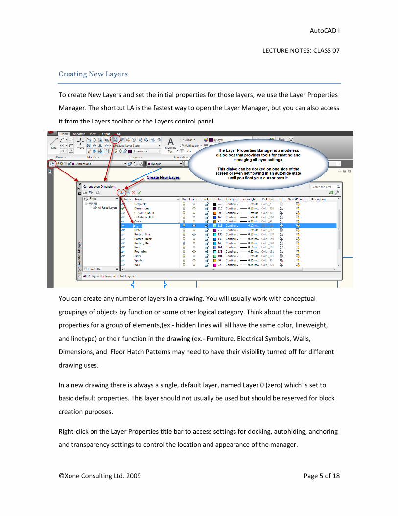
Creating New Layers
To create New Layers and set the initial properties for those layers, we use the Layer Properties
Manager. The shortcut LA is the fastest way to open the Layer Manager, but you can also access
it from the Layers toolbar or the Layers control panel.
You can create any number of layers in a drawing. You will usually work with conceptual
groupings of objects by function or some other logical category. Think about the common
properties for a group of elements,(ex - hidden lines will all have the same color, lineweight,
and linetype) or their function in the drawing (ex.- Furniture, Electrical Symbols, Walls,
Dimensions, and Floor Hatch Patterns may need to have their visibility turned off for different
drawing uses.
In a new drawing there is always a single, default layer, named Layer 0 (zero) which is set to
basic default properties. This layer should not usually be used but should be reserved for block
creation purposes.
Right-click on the Layer Properties title bar to access settings for docking, autohiding, anchoring
and transparency settings to control the location and appearance of the manager.

AutoCAD I
LECTURE NOTES: CLASS 07
©Xone Consulting Ltd. 2009 Page 6 of 18
Layer names should be descriptive. The default names of Layer1, Layer2, Layer3, etc. will not
mean nearly as much as a layer called A-Wall-Demo. (Architectural Walls to be Demolished)
The Layer Properties Manager sorts layers alphabetically by name as well as any other category.
If you're organizing your own layer scheme, name layers carefully to take advantage of the
sorting capabilities. (Ex. -Start all architectural layers with an “A-“)
Assign Default Properties to a Layer
After creating a new layer, you can set default properties for the layer by choosing a color, a
linetype, and a lineweight. The default values for these properties will be set to the color white,
a continuous linetype, and a default lineweight of .25mm
To set the properties for a new layer, pick any of the categories to the right of the layer name,
such as the color swatch, the linetype name, or the lineweight value and it will open a new
dialog box where you can choose the desired property for that layer.
AutoCAD I
LECTURE NOTES: CLASS 07
©Xone Consulting Ltd. 2009 Page 7 of 18
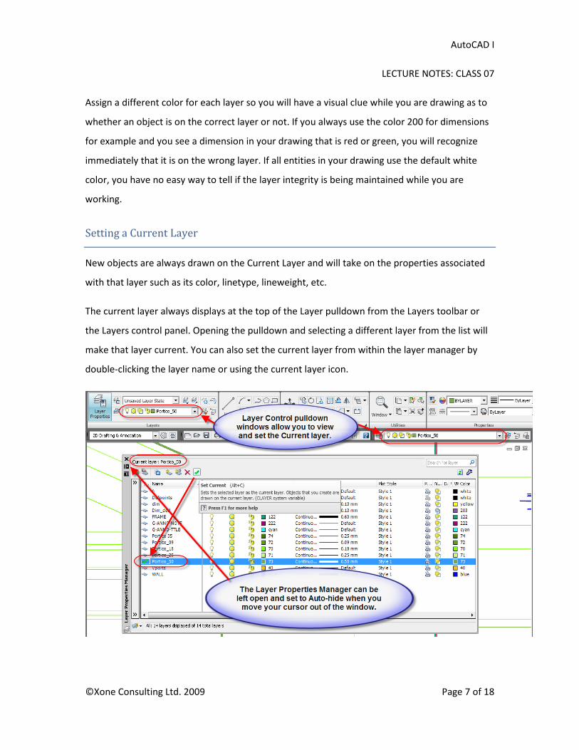
Assign a different color for each layer so you will have a visual clue while you are drawing as to
whether an object is on the correct layer or not. If you always use the color 200 for dimensions
for example and you see a dimension in your drawing that is red or green, you will recognize
immediately that it is on the wrong layer. If all entities in your drawing use the default white
color, you have no easy way to tell if the layer integrity is being maintained while you are
working.
Setting a Current Layer
New objects are always drawn on the Current Layer and will take on the properties associated
with that layer such as its color, linetype, lineweight, etc.
The current layer always displays at the top of the Layer pulldown from the Layers toolbar or
the Layers control panel. Opening the pulldown and selecting a different layer from the list will
make that layer current. You can also set the current layer from within the layer manager by
double-clicking the layer name or using the current layer icon.

AutoCAD I
LECTURE NOTES: CLASS 07
©Xone Consulting Ltd. 2009 Page 8 of 18
Because everything in your drawing is associated with a layer, it's likely that in the course of
planning and creating a drawing, you'll need to change what you place on a layer or how you
view the layers in combination. You can
• Reassign objects from one layer to another.
• Change the name of a layer.
• Change the default color, linetype, or other properties of the layer.
Layer Tools
Several useful tools are found on the Layers
control panel
Make Object’s Layer Current let’s you set the
current layer by first picking an object in the
drawing and then selecting this tool.
Layer Match changes the layer of a selected
object to the layer of a destination object.
Layer Previous allows you to undo any
changes made to layer settings.
Isolate and Unisolate hides and unhides all objects not in the current selection set. When you
isolate a layer, all other layers in the drawing will either be locked so they can't be modified or
turned off so they are not visible. Isolate Layer Settings may be accessed from the Settings tool
(wrench icon)in the upper right corner of the Layer Properties Manager.
Freeze and Off tools change the visibility of a selected object’s layer.
Several other layer tools are available in the advanced section of the Layer Panel, including
options to Delete a layer and all objects on that layer, changing objects to the current layer,
freezing all layers, locking all layers, merging items on a single layer, and more.

AutoCAD I
LECTURE NOTES: CLASS 07
©Xone Consulting Ltd. 2009 Page 9 of 18
Control Whether Objects on a Layer Can Be Modified
If you wish to see the objects on a particular layer, but you do not want to be able to
modify those entities, you can lock their layer. You can still access locked layers with
regards to Object snapping or Tracking but you cannot edit them.
Locked layers remain visible but appear faded. The amount of fading can be set in the
Layer Control Panel’s expanded settings area form 0% (no fading) to a maximum of 90%
at which objects will be barely visible.
Control Whether Objects on a Layer will be Plotted
If you wish to see the objects on a particular layer, but you do not want them to be
plotted, you can modify the layer’s plotting status in the Layer Manager.

AutoCAD I
LECTURE NOTES: CLASS 07
©Xone Consulting Ltd. 2009 Page 10 of 18
Colors
Color helps to group objects visually. You can assign colors to objects by layer (recommended)
or individually. You can change the color of an object by reassigning it to another layer, by
changing the color of the layer the object is on, or by specifying a color for the object explicitly.
Index colors are the standard colors used in AutoCAD. Each color is identified by an ACI
(AutoCAD Color Index) number, an integer from 1 through 255. Standard color names are
available only for colors 1 through 7. The colors are assigned as follows: 1 Red, 2 Yellow, 3
Green, 4 Cyan, 5 Blue, 6 Magenta, 7 White/Black.
True colors use 24-bit color definitions to display over 16 million colors. When specifying true
colors, you can use either an RGB or HSL color model. With the RGB color model, you can
specify the red, green, and blue components of the color; with the HSL color model, you can
specify the hue, saturation, and luminance aspects of the color.

AutoCAD I
LECTURE NOTES: CLASS 07
©Xone Consulting Ltd. 2009 Page 11 of 18
Color Books provide a third option for choosing a color and are based on recognized color
standards such as Pantone, DIC, or RAL colors. For general drafting purposes one of the Index
colors should be sufficient while True colors and color Books can be used to define colors for
material creation in the process of rendering realistic images.
All objects are created using the current color, which is displayed in the color control on the
Properties toolbar. You can also set the current color with the color control or the Select color
dialog box.
If the current color is set to BYLAYER, objects are created with the color assigned to the current
layer. If you do not want the current color to be the color assigned to the current layer, you can
specify a different color.
If the current color is set to BYBLOCK, objects are created using color 7 (white or black) until the
objects are grouped into a block. When the block is inserted into the drawing, it acquires the
current color setting.
It is very rare that you should need to assign colors explicitly. Layers provide a much faster and
more efficient way to manage the color of a group of objects. In a typical drawing, all values on
the Properties Panel or Properties toolbar should be set to BYLAYER.

AutoCAD I
LECTURE NOTES: CLASS 07
©Xone Consulting Ltd. 2009 Page 12 of 18
Linetypes and Linetype Scales
Linetypes are used to distinguish objects and offer further description about the entities being
shown. The most common non-continuous linetype is the Hidden line, used to show edges or
features which would not normally be visible from the current viewing direction. Other
common non-continuous lines are center lines and phantom lines.
A linetype may be continuous or it may display a repeating pattern of dashes, dots and spaces.
The relative spacing of the pattern’s elements is controlled through linetype scales which may
be set globally or with explicit overrides.
All objects created will have a linetype associated with them which is controlled through the
Layer settings (Bylayer - recommended) or by object (Explicit – rarely required).
AutoCAD I
LECTURE NOTES: CLASS 07
©Xone Consulting Ltd. 2009 Page 13 of 18
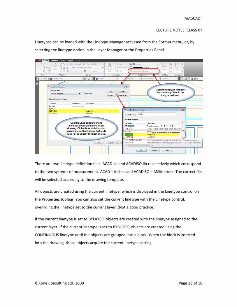
Linetypes can be loaded with the Linetype Manager accessed from the Format menu, or, by
selecting the linetype option in the Layer Manager or the Properties Panel.
There are two linetype definition files: ACAD.lin and ACADISO.lin respectively which correspond
to the two systems of measurement. ACAD – Inches and ACADISO – Millimeters. The correct file
will be selected according to the drawing template.
All objects are created using the current linetype, which is displayed in the Linetype control on
the Properties toolbar. You can also set the current linetype with the Linetype control,
overriding the linetype set to the current layer. (Not a good practice.)
If the current linetype is set to BYLAYER, objects are created with the linetype assigned to the
current layer. If the current linetype is set to BYBLOCK, objects are created using the
CONTINUOUS linetype until the objects are grouped into a block. When the block is inserted
into the drawing, those objects acquire the current linetype setting.

AutoCAD I
LECTURE NOTES: CLASS 07
©Xone Consulting Ltd. 2009 Page 14 of 18
Linetype Scales
The relative size of the dashes and spaces in a non-continuous linetype is controlled by the
global linetype scale factor, LTSCALE and the individual linetype scale factor, CELTSCALE. The
CELTSCALE value is multiplied by the LTSCALE value to get the displayed linetype scale. Other
settings that affect the display of linetypes are PSLTSCALE and MSLTSCALE.
Most typical linetypes
such as hidden,
dashed, center, etc.
have 3 variations
distinguished by the
presence of a “2” or an
“X2” at the end of the
linetype name. For
most purposes, choosing the variation that ends in “2” will yield the best results.
LTSCALE - In a single layout drawing, not using annotation scaling, to view linetypes in Model
Space, set LTSCALE equal to the intended viewport scale. i.e. –For 1”=1’-0”, set LTSCALE to 12.
In current versions of AutoCAD leave LTSCALE at 1 if you are using annotation scaling.
MSLTSCALE –This setting allows automatic scaling of linetypes based on the current annotation
scale or viewport scale. Leave this value at its default of 1 and LTSCALE can also be left at 1.
Linetypes will be scaled based on the annotation scale setting on the status bar.
CELTSCALE - Always leave CELTSCALE at 1. This should be applied only to individual segments
that are too small to display the dashes at a normal scale. Double-click the object to access its
linetype scale in the properties palette and set it to .5 or .25 to reduce the length of the dashes
and spaces to 50% or 25% of the default length.
PSLTSCALE –Leave this setting at its default of 1 to enable scaling of linetypes based on the
viewport scale.

AutoCAD I
LECTURE NOTES: CLASS 07
©Xone Consulting Ltd. 2009 Page 15 of 18
3. Lineweights
You can differentiate objects in your drawing by controlling their lineweights both in the
drawing display and in plotting. For example, Sectioned objects should read heavier than
objects in elevation and all object lines should be heavier than dimension lines, which in turn
should be heavier than hatch pattern lines.
Using lineweights, you can impart a human feel to your drawings and make them easier to read.
A minimum of 3 lineweights is recommended in even the simplest drawings and in a large,
complex elevation you may use 5, 7, or even more to distinguish between elements of different
importance.
As with other properties, Lineweights are most easily controlled by assigning them to layers and
then grouping similar objects on specific layers.
To view lineweights in your drawing editor, you need to enable the Lineweight toggle on your
status bar. (LWT icon.)

AutoCAD I
LECTURE NOTES: CLASS 07
©Xone Consulting Ltd. 2009 Page 16 of 18
Lineweights are displayed differently in model space than in a paper space layout. In model
space, lineweights will appear to change thickness when you zoom in and out while working.
You cannot view lineweights properly in the Model tab.
When you are working on your Layouts in Paper Space, lineweights do display properly based
on the scale of the viewport and the plot scale setup. Essentially, you have a “live plot preview”
of the relative thicknesses of the lines in your drawing as they will appear on the plotted sheet
of paper. If two edges blur together here, they will also plot as a single thin line when you print
the drawing.
All objects are created using the current lineweight, which is displayed in the Lineweight control
on the Properties toolbar. You can also set the current lineweight with the Lineweight control.
If the current lineweight is set to BYLAYER, objects are created with the lineweight assigned to
the current layer.
As with all general properties, the lineweight setting is most easily controlled through the
BYLAYER setting. Changing a single value in the layer manager can affect the properties of
hundreds of entities. (Unless they have explicit properties applied.)

AutoCAD I
LECTURE NOTES: CLASS 07
©Xone Consulting Ltd. 2009 Page 17 of 18
This graphic depicts a sample set of lineweights for various types of entities in a drawing. The
actual line widths are being approximated in this image due to the conversion to a raster image.
See sample drawing for a more accurate depiction of the lineweights.
AutoCAD I
LECTURE NOTES: CLASS 07
©Xone Consulting Ltd. 2009 Page 18 of 18
4. Practice Drawings – Layers, Properties and Layouts
In the following drawing exercises, you will learn how to setup realistic technical drawings that
require more detailed depictions of lineweights and linetypes. You will organize the drawing
information through the use of Layers.
When the drawing is complete, access Layout 1, create a viewport, set the scale for the view,
compose the drawing views on the sheet and lock the display of the viewport.
Refer to the drawing file pages for lesson 7, and recreate the practice drawing of the Idler Plate
as shown. Start the file with the CADD1-B2.dwt template. Create a new layer called Plate, set its
color to Magenta and its lineweight to 0.50mm. Set the new layer current and draw the plate as
shown. Start with circles and construction lines and then use the fillet command to create
tangential arcs between the circles.
Save the file as Practice-7a in the Practice folder you created in lesson 1.When the drawing is
complete, back it up by copying the file to a removable drive.
5. Assignment Drawing 4 – Layers, Properties and Layouts
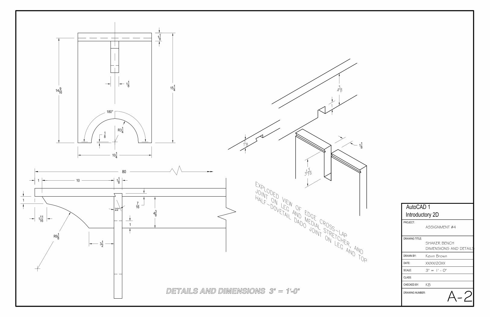
Referring to the drawing file pages for lesson 7, complete the assignment drawing of the
Hancock Meeting Room Bench as shown on the Sheet A1. Do not draw the detail drawings or
the isometric view shown on Sheet A2. They are for your reference only.
After completing the drawing, switch to Layout 1 and create a single viewport. Set the scale to 1
½” = 1’ – 0”, centre the view, and then lock the viewport display.
The main titles as well as the titleblock text information are required and will be added in the
next class. Dimensions are not required.
Save the file as CADD1_4_Your Name.dwg in your assignments folder. Back up your drawing file
as usual. Send a copy of the file to your instructor for evaluation when it is complete. It is due
by the end of Class 10.


Kevin
Polygon
Kevin
Callout
Add both titles on the Titles layer. Use a different custom text style for each line. Preset style heights to 1/4" and 1/8".
Kevin
Polygon
Kevin
Callout
180 degree arc raised on 1/8" vertical segments at either end of arc
Kevin
Polygon
Kevin
Callout
Complete titleblock, adding info on Notes layer, using a third custom text style with height set to 3/32".
Kevin
Polygon
Kevin
Callout
Check all short hidden lines to ensure they display a gap. Set a linetype scale override of 0.5 for all short hidden line segments.
Kevin
Polygon
Kevin
Callout
Make sure all hidden lines are added and displayed correctly.
Kevin
Text Box
Ensure viewport scale is set and viewport is Display Locked
Kevin
Text Box
Makes sure all layer properties are set correctly.
Kevin
Text Box
Make sure Viewport is created on the Vports layer and is either set to non-plotting status or is turned off.
Kevin
Text Box
Makes sure viewport is smaller than the overall sheet size and does not extend outside sheet border.
Kevin
Polygon
Kevin
Callout
Makes sure all lines are trimmed correcty at joint and where stretcher crosses legs.
Kevin
Text Box
Add Titles and Titleblock text in Paper Space.
Kevin
Line
Kevin
Line
Kevin
Line
Kevin
Line
Kevin
Text Box
Use temporary construction lines to ensure features are aligned between related views.
Kevin
Line
Kevin
Line
Related Documents


![1 1 1 1 1 1 1 ¢ 1 , ¢ 1 1 1 , 1 1 1 1 ¡ 1 1 1 1 · 1 1 1 1 1 ] ð 1 1 w ï 1 x v w ^ 1 1 x w [ ^ \ w _ [ 1. 1 1 1 1 1 1 1 1 1 1 1 1 1 1 1 1 1 1 1 1 1 1 1 1 1 1 1 ð 1 ] û w ü](https://static.cupdf.com/doc/110x72/5f40ff1754b8c6159c151d05/1-1-1-1-1-1-1-1-1-1-1-1-1-1-1-1-1-1-1-1-1-1-1-1-1-1-w-1-x-v.jpg)