136-9800 Manual Rev B.doc Met One Instruments, Inc 1600 Washington Blvd. Grants Pass, Oregon 97526 Telephone 541-471-7111 Facsimile 541-471-7116 Regional Service 3206 Main St. Suite 106 Rowlett, Texas 75088 Telephone 972-412-4715 Facsimile 972-412-4716 136 MULTI-MET INTERFACE MODULE OPERATION MANUAL 136-9800 REV B

Welcome message from author
This document is posted to help you gain knowledge. Please leave a comment to let me know what you think about it! Share it to your friends and learn new things together.
Transcript
136-9800 Manual Rev B.doc
Met One Instruments, Inc
1600 Washington Blvd.
Grants Pass, Oregon 97526 Telephone 541-471-7111 Facsimile 541-471-7116
Regional Service 3206 Main St. Suite 106 Rowlett, Texas 75088 Telephone 972-412-4715 Facsimile 972-412-4716
136 MULTI-MET INTERFACE MODULE
OPERATION MANUAL 136-9800 REV B

136-9800 Manual Rev B.doc Page 2
Copyright Notice 136 MULTI-MET® DATA COLLECTION PACKAGE OPERATION MANUAL © Copyright 2019 Met One Instruments, Inc. All Rights Reserved Worldwide. No part of this publication may be reproduced, transmitted, transcribed, stored in a retrieval system, or translated into any other language in any form by any means without the express written permission of Met One Instruments, Inc.
Technical Support
Should you require support, please consult your printed documentation to resolve your problem. If you are still experiencing difficulty, you may contact a Technical Service representative during normal business hours—7:30 a.m. to 4:00 p.m. Pacific Time, Monday through Friday.
Voice: (541) 471-7111
Fax: (541) 471-7116
E-Mail: [email protected]
Mail: Technical Services Department Met One Instruments, Inc. 1600 Washington Boulevard Grants Pass, OR 97526
136-9800 Manual Rev B.doc Page 3
Table of Contents
1. General Information........................................................................................................................... 5
1.1. Introduction ................................................................................................................................ 5
1.2. Description ................................................................................................................................. 5
1.3. Specifications ............................................................................................................................. 6
2. Installation .......................................................................................................................................... 8
2.1. Mounting .................................................................................................................................... 8 2.1.1. 136 Module .......................................................................................................................... 8 2.1.2. 136WP Weather Proof Interface Module ............................................................................ 9 2.1.3. 136RM Rack Mount Interface Module ................................................................................. 9
2.2. Wiring ....................................................................................................................................... 10
2.3. Power ....................................................................................................................................... 10
2.4. RS232 Cable Connection ........................................................................................................ 10
2.5. USB Cable Connection ............................................................................................................ 11
2.6. Modem Options ........................................................................................................................ 11
2.7. Printer Port (COM2) ................................................................................................................. 11
2.8. ADA / Digital Serial Sensor COM Port ..................................................................................... 11
3. Operation .......................................................................................................................................... 12
3.1. Comet II Software Operation ................................................................................................... 12
3.2. Main Menu ............................................................................................................................... 13 3.2.1. Navigation and Editing Keys .............................................................................................. 13 3.2.2. Setup Menu Overview ....................................................................................................... 15 3.2.3. Operate Menu Overview .................................................................................................... 16 3.2.4. Test Menu Overview.......................................................................................................... 16
4. Setup Menu ...................................................................................................................................... 17
4.1. Setup Clock .............................................................................................................................. 17
4.2. Setup Sensor ........................................................................................................................... 18 4.2.1. Sensor Setup Introduction ................................................................................................. 18 4.2.2. Viewing the Sensor Setup ................................................................................................. 18 4.2.3. Editing the Sensor Setup ................................................................................................... 18 4.2.4. Viewing Channel Scaling ................................................................................................... 20 4.2.5. Set Analog Channel Scaling .............................................................................................. 21 4.2.6. Set Counter Wind Speed Scaling ...................................................................................... 22 4.2.7. Set Auto ID Sensor Scaling ............................................................................................... 22 4.2.8. Special Settings for Thermistor Temperature Channels 3 and 4 ...................................... 23 4.2.9. Special Settings for Millivolt Channels 7 and 8 .................................................................. 24 4.2.10. Special Settings for Rain Gauge ....................................................................................... 27
4.3. Setup Average Period .............................................................................................................. 28
4.4. Setup Station ID ....................................................................................................................... 28
4.5. Voltage Output ......................................................................................................................... 29
4.6. Voltage Input ............................................................................................................................ 29
4.7. Digital Sensor ........................................................................................................................... 30 4.7.1. Digital Selection Screen .................................................................................................... 30 4.7.2. Digital Change Detected .................................................................................................... 37
136-9800 Manual Rev B.doc Page 4
4.8. Setup Alarms ........................................................................................................................... 38 4.8.1. Alarm Options .................................................................................................................... 38
4.9. Setup Reports .......................................................................................................................... 40
4.10. Setup Baud .............................................................................................................................. 40
4.11. Setup Modbus .......................................................................................................................... 41
4.12. Setup Password ....................................................................................................................... 41
4.13. Setup Communications Screen ............................................................................................... 42
4.14. Setup About Screen ................................................................................................................. 42
5. Operate Menu ................................................................................................................................... 42
5.1. Memory Use ............................................................................................................................. 43
6. Test Menu ......................................................................................................................................... 43
6.1. Test Alarm................................................................................................................................ 44
6.2. Test Voltage Output ................................................................................................................. 44
6.3. Test Calibrate ........................................................................................................................... 45
7. RS232 Communication.................................................................................................................... 46
7.1. RS232 Port Description ........................................................................................................... 46
7.2. USB .......................................................................................................................................... 46
7.3. Modem Option ......................................................................................................................... 47
7.4. Cloud Option ............................................................................................................................ 47
7.5. RS232 Main Menu ................................................................................................................... 48
7.6. Extended Command Menu ...................................................................................................... 49
8. Troubleshooting .............................................................................................................................. 50
9. Technical Support ........................................................................................................................... 50
10. Factory Repair and Calibration ...................................................................................................... 50
11. Appendices....................................................................................................................................... 51
11.1. Appendix A – RS232 Commands ............................................................................................ 51
11.2. Appendix B – Extended Commands ........................................................................................ 56
11.3. Appendix C – Updating Firmware ............................................................................................ 57
11.4. Appendix D – Wiring Panel Technical Data ............................................................................. 58
11.5. Appendix E – Serial Output Record Formats ........................................................................... 61 11.5.1. MetRecord Format ............................................................................................................ 61 11.5.2. UIM Record Format ........................................................................................................... 62 11.5.3. Status Field Format ........................................................................................................... 63 11.5.4. Record Checksums ........................................................................................................... 63
11.6. Appendix F – Wind Direction Sensor Orientation .................................................................... 64
11.7. Appendix G – 136 Data logger Multiplier & Offset Examples .................................................. 70
11.8. Appendix H – Calculation of Max Engr and Min Engr for AT Measurements .......................... 72
11.9. Appendix I – USB Driver Installation Instructions .................................................................... 73
136-9800 Manual Rev B.doc Page 5
1. General Information
1.1. Introduction
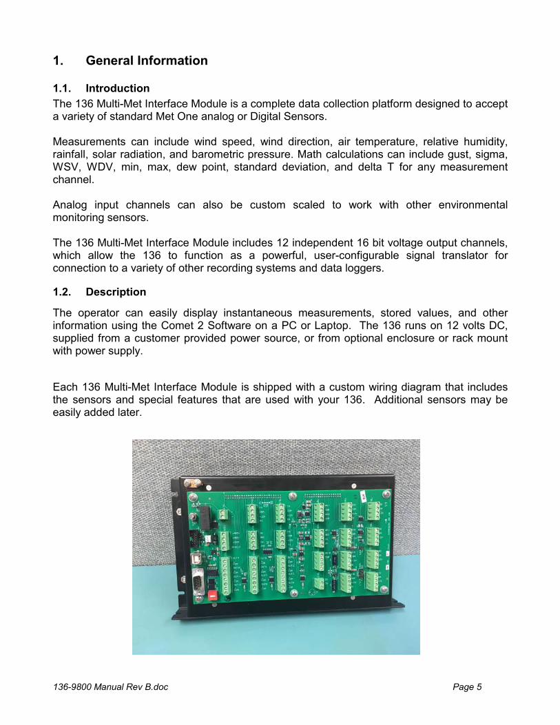
The 136 Multi-Met Interface Module is a complete data collection platform designed to accept a variety of standard Met One analog or Digital Sensors. Measurements can include wind speed, wind direction, air temperature, relative humidity, rainfall, solar radiation, and barometric pressure. Math calculations can include gust, sigma, WSV, WDV, min, max, dew point, standard deviation, and delta T for any measurement channel. Analog input channels can also be custom scaled to work with other environmental monitoring sensors. The 136 Multi-Met Interface Module includes 12 independent 16 bit voltage output channels, which allow the 136 to function as a powerful, user-configurable signal translator for connection to a variety of other recording systems and data loggers.
1.2. Description
The operator can easily display instantaneous measurements, stored values, and other information using the Comet 2 Software on a PC or Laptop. The 136 runs on 12 volts DC, supplied from a customer provided power source, or from optional enclosure or rack mount with power supply.
Each 136 Multi-Met Interface Module is shipped with a custom wiring diagram that includes the sensors and special features that are used with your 136. Additional sensors may be easily added later.
136-9800 Manual Rev B.doc Page 6
1.3. Specifications
Analog Sensor Inputs
8 single ended 0-2.5 or 0-5 VDC user selectable with Auto ID Sensor option.
2 Millivolt amplifiers (x10 and x100 Solar with selectable 100 ohm loads)
Special Input
2 Frequency Counters (Wind Speed frequency selectable as low range, high range, or low millivolt)
1 Rain Gauge Channel (De-bounced switch closure with pull up resistor to 5 volts)
Digital Sensor Inputs
Multiple Digital Sensors, 16 channels maximum (RS232 on ADA port or RS485 on RS485 port)
Supported Met One Instruments, Inc. Digital Sensors include but are not limited to:
o AIO, AIO 2 Sonic Weather Station
o MSO-232 5 Parameter Weather Station
o 597, 598 Temperature, Relative Humidity and Pressure Sensor
o TACMET II Military Sonic Weather Station
o ES-642 Network Particulate Monitor
o NPM2 Remote Dust Monitor
Voltage Outputs
12 Voltage Output Channels
16 Bits Unipolar
5.000VDC full scale (Can be scaled to 1.000 or 2.500 VDC full scale)
+/- 4 millivolts accuracy (of expected reading).
Uncompensated for signal cable voltage gradient.
Alarm Outputs
2 Alarm channels with N.O. relay contacts (Max. power 24 VDC at 20 mA)
Communication
Main RS-232C port, 1200-115200 Baud (Default 9600), ASCII, N,8,1; 19200
Printer or Computer RS-232C (COM2), 1200-115200 Baud (Default 9600), ASCII, N,8,1;
ADA / Digital Sensor RS232 9600 Baud Fixed
RS-422/485 output or Digital Sensor input, 9600 Baud
RS-232 Extra Port 1200-115200 Baud
USB for computer communications; shared port with Main RS-232C Port
136-9800 Manual Rev B.doc Page 7
Protocol
7500 MetRecord Protocol for Digital Sensors and Serial Communications
UIM Serial Report String (optional)
MODBUS (RTU)
Log Channels
8 sensor logging channels (Combination of digital and/or analog)
Sigma (Yammartino Method)
Rain
Battery Voltage
Max/Min Calculations
Gust (3 Second average)
WSV/WDV Calculations
Dew Point Calculation
Logging Data Capacity
1Min data 7.2 days
5Min data 36 days
10Min data 72 days
15Min data 108 days
30Min data 216 days
60Min data 433 days (1.2 years)
Power Requirement
12VDC ± 20% 50 mA or less
Environmental
Operating Temperature Range: -20°C to +60°C
Physical Specifications Dimensions 11.5 in (292 mm) wide, 6.62” (168 mm) high, 2.5” (64 mm) thick
Weight
Weight 2 lbs (0.91 kg)
136-9800 Manual Rev B.doc Page 8
2. Installation
2.1. Mounting
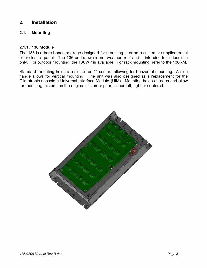
2.1.1. 136 Module
The 136 is a bare bones package designed for mounting in or on a customer supplied panel or enclosure panel. The 136 on its own is not weatherproof and is intended for indoor use only. For outdoor mounting, the 136WP is available. For rack mounting, refer to the 136RM. Standard mounting holes are slotted on 1” centers allowing for horizontal mounting. A side flange allows for vertical mounting. The unit was also designed as a replacement for the Climatronics obsolete Universal Interface Module (UIM). Mounting holes on each end allow for mounting this unit on the original customer panel either left, right or centered.
136-9800 Manual Rev B.doc Page 9
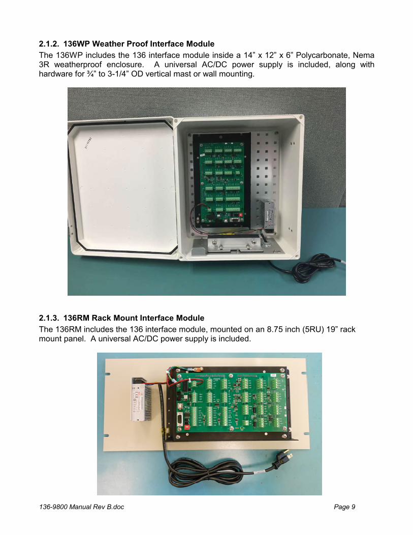
2.1.2. 136WP Weather Proof Interface Module
The 136WP includes the 136 interface module inside a 14” x 12” x 6” Polycarbonate, Nema 3R weatherproof enclosure. A universal AC/DC power supply is included, along with hardware for ¾” to 3-1/4” OD vertical mast or wall mounting.
2.1.3. 136RM Rack Mount Interface Module
The 136RM includes the 136 interface module, mounted on an 8.75 inch (5RU) 19” rack mount panel. A universal AC/DC power supply is included.
136-9800 Manual Rev B.doc Page 10
2.2. Wiring
When purchased with sensors, the 136 Multi-Met Interface Module is programmed and fully tested at the factory as a complete system with all purchased cables and sensors. The cables may or may not be attached during shipping. If necessary, connect the wires as shown in the supplied System Interconnect Diagram(s) customized for your system.
If using the 136WP, ensure the seal clamp is tightened around the cable bundle entering the enclosure. Clamp the wires by first tightening the internal clamp screws and then by tightening the external clamp screws. Finally, tug lightly on the cables to be sure they are clamped, and the seal is in place.
A grounding lug is provided on the panel of the 136. This must be connected to an Earth ground to provide necessary surge protection for the sensor signal line inputs.
2.3. Power
When used alone, 12 VDC power can be directly tied to the terminal block (TB19) on the wiring panel of the 136. Onboard fuse and reverse polarity protection are employed.
When using the 136WP or 136RM with included universal AC/DC power supplies, plug the AC power cable into an AC power outlet. When used outdoors, a weatherproof cover such as the Carlin Model E9UDVG should be used on the AC outlet box.
2.4. RS232 Cable Connection
Connect the RS-232 (P/N 2443) cable between the 136 and the host computer’s 9 pin RS-232 port. One connector is marked “logger” and the other end is marked “PC”, be sure they are connected to the correct ends.
NOTE: A standard serial cable will not work. The custom RS-232 cable supplied with the logger must be used.
WARNING!
Do not confuse the computer VGA video adapter connectors as RS-232 COM ports. Connecting to these will cause damage to your computer, and/or the equipment being connected to it. Normally RS-232 connections on PC have male pins vs. female socket type connectors. If in doubt, consult the owner’s manual or check with your computer dealer before making any connections. If the computer does not have an RS-232 port then a USB to RS-232 adapter must be used or connection made using the USB connection on the 136 wiring panel. See the USB section below.
By default, the 136 RS-232 port is set up to communicate at 9600 Baud, No parity, 8 data bits, 1 stop (9600 N 8 1). Using the BAUD Rate Setup Menu, the port can be configured for other BAUD rates.
NOTE: See section 6 for additional information.
136-9800 Manual Rev B.doc Page 11
2.5. USB Cable Connection
The 136 uses a male type A to Male type B cable for connection to the PC. Connect the USB cable (P/N 500784) between the 136 and the host computer USB port. The USB serial drivers, located on the Comet CD (P/N 80248), will need to be installed on the host computer prior to trying to communicate with the 136.
The USB serial drivers allow the host computer to communicate to the 136 using the Air Plus 5, Comet 2 or any standard serial communications program.
2.6. Modem Options
There are several modem and radio communications options. Consult the manual for the optional device for connection information.
2.7. Printer Port (COM2)
A printer port is provided for Auto-Printing RS-232 data and can be connected to a serial printer, computer, or other RS-232 logging device. The 136 printer port has the option to print MetRecord or UIM records as OFF, 1 second, 10 second, 1 minute, 5 minute, or 10-minute intervals. This setting is independent of the main port record output and allows dual types of record output if needed.
The 136 printer port will communicate at 1200 thru 115,200 Baud, No parity, 8 data bits, and 1 stop bit.
2.8. ADA / Digital Serial Sensor COM Port
The ADA port can be connected to an optional Automatic Direction Alignment (ADA) unit attached to the wind direction sensor.
The logger can also be set up to use this port for retrieving measurements from a Met One Digital Serial meteorological sensor.
Refer to the Digital Sensor Setup section of the manual for installation instructions.
136-9800 Manual Rev B.doc Page 12
3. Operation
3.1. Comet II Software Operation
The 136 Multi-Met is not provided with an external keyboard or display. It makes use of a PC based program called Comet II and is supplied with the unit. The Comet II program allows the user to setup and program the unit, and view real time and recorded average data.
When connected to the 136, and the “Remote Ctrl” menu tab is selected, the program will connect to the 136 and bring up a graphical screen that is used for viewing and programming.
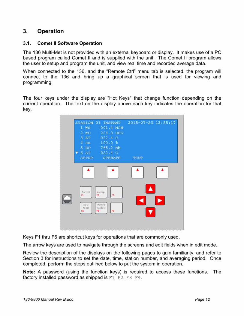
The four keys under the display are "Hot Keys" that change function depending on the current operation. The text on the display above each key indicates the operation for that key.
Keys F1 thru F6 are shortcut keys for operations that are commonly used.
The arrow keys are used to navigate through the screens and edit fields when in edit mode.
Review the description of the displays on the following pages to gain familiarity, and refer to Section 3 for instructions to set the date, time, station number, and averaging period. Once completed, perform the steps outlined below to put the system in operation.
Note: A password (using the function keys) is required to access these functions. The factory installed password as shipped is F1 F2 F3 F4.
136-9800 Manual Rev B.doc Page 13
After making any changes, save the changes, exit, and then verify your changes are active. If you have problems, review the steps again and if necessary, contact Customer Service for assistance.
Continue to set the rest of the functions using the display.
Press the OPERATE then INST keys. Verify displayed data is representative of actual conditions.
Data will be recorded automatically; refer to the RS232 Communications section for instructions to retrieve data.
3.2. Main Menu
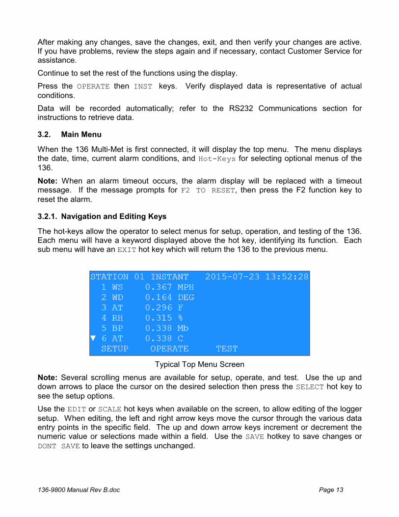
When the 136 Multi-Met is first connected, it will display the top menu. The menu displays the date, time, current alarm conditions, and Hot-Keys for selecting optional menus of the 136.
Note: When an alarm timeout occurs, the alarm display will be replaced with a timeout message. If the message prompts for F2 TO RESET, then press the F2 function key to reset the alarm.
3.2.1. Navigation and Editing Keys
The hot-keys allow the operator to select menus for setup, operation, and testing of the 136. Each menu will have a keyword displayed above the hot key, identifying its function. Each sub menu will have an EXIT hot key which will return the 136 to the previous menu.
Typical Top Menu Screen
Note: Several scrolling menus are available for setup, operate, and test. Use the up and down arrows to place the cursor on the desired selection then press the SELECT hot key to see the setup options.
Use the EDIT or SCALE hot keys when available on the screen, to allow editing of the logger setup. When editing, the left and right arrow keys move the cursor through the various data entry points in the specific field. The up and down arrow keys increment or decrement the numeric value or selections made within a field. Use the SAVE hotkey to save changes or DONT SAVE to leave the settings unchanged.

136-9800 Manual Rev B.doc Page 14
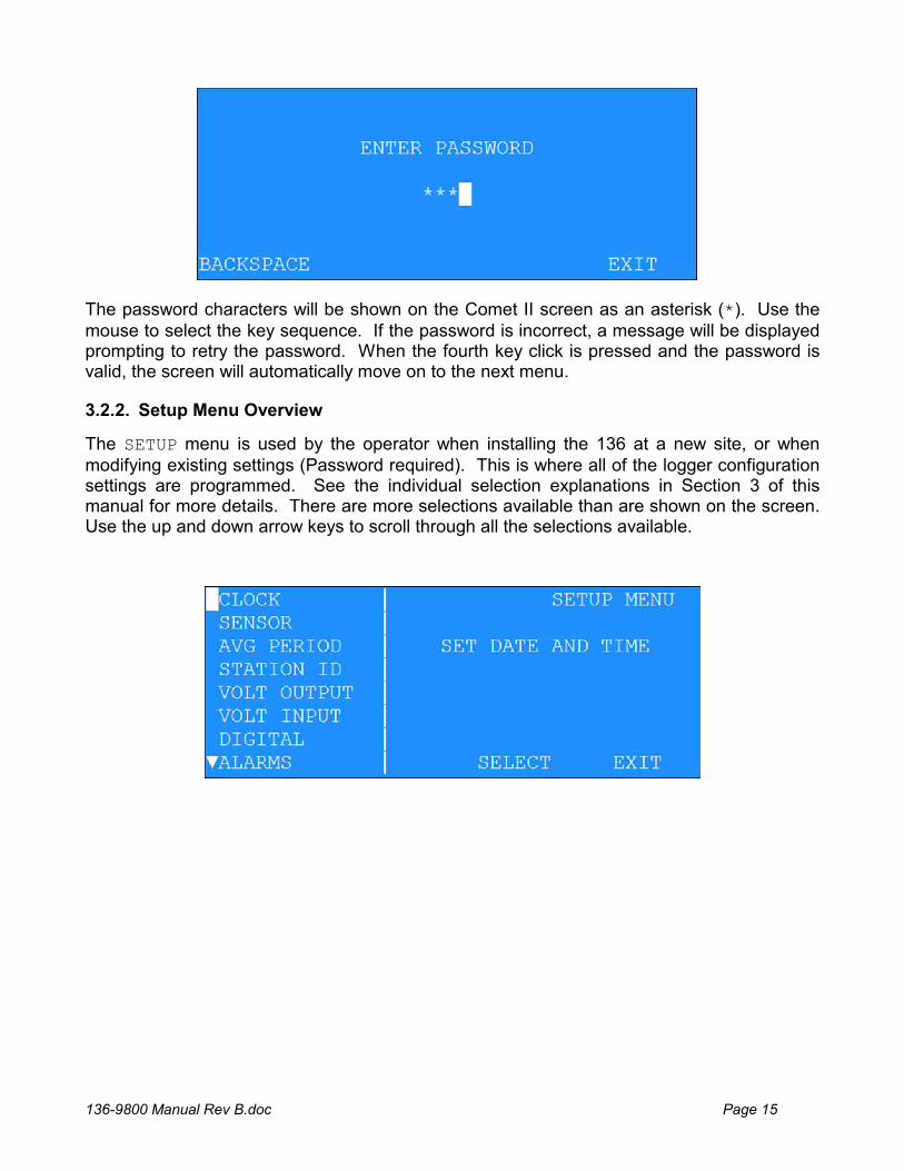
For the setup and test menus, the operator must first enter a four-keystroke password to enable access to these menus (136 comes from the factory with the sequence F1 F2 F3 F4). When entering the password, the following screen will be shown:
136-9800 Manual Rev B.doc Page 15
The password characters will be shown on the Comet II screen as an asterisk (*). Use the mouse to select the key sequence. If the password is incorrect, a message will be displayed prompting to retry the password. When the fourth key click is pressed and the password is valid, the screen will automatically move on to the next menu.
3.2.2. Setup Menu Overview
The SETUP menu is used by the operator when installing the 136 at a new site, or when modifying existing settings (Password required). This is where all of the logger configuration settings are programmed. See the individual selection explanations in Section 3 of this manual for more details. There are more selections available than are shown on the screen. Use the up and down arrow keys to scroll through all the selections available.
136-9800 Manual Rev B.doc Page 16
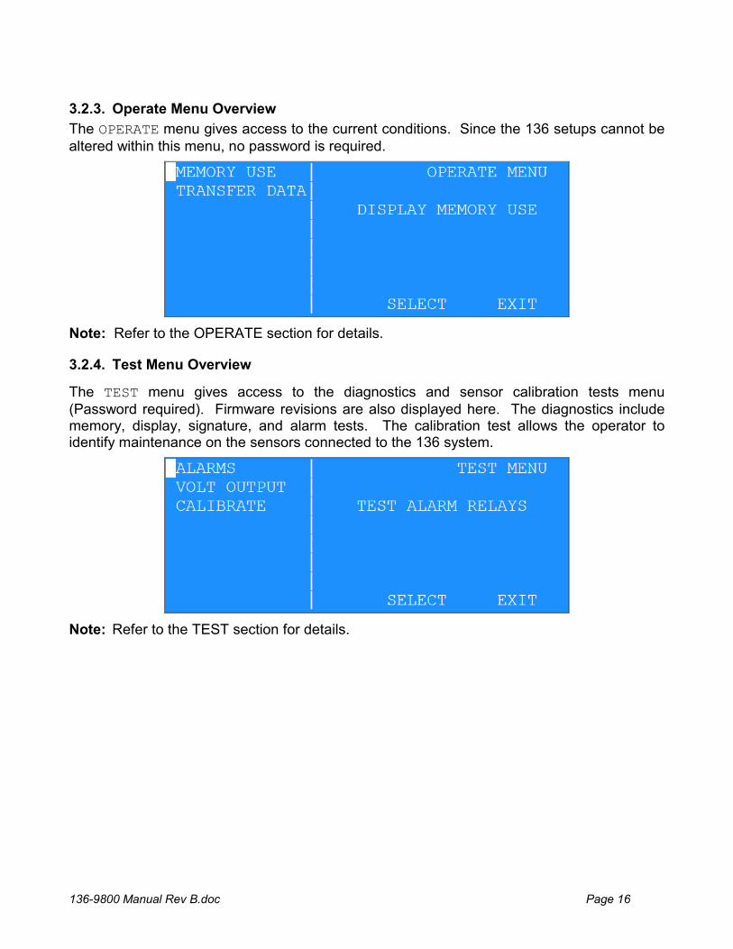
3.2.3. Operate Menu Overview
The OPERATE menu gives access to the current conditions. Since the 136 setups cannot be altered within this menu, no password is required.
Note: Refer to the OPERATE section for details.
3.2.4. Test Menu Overview
The TEST menu gives access to the diagnostics and sensor calibration tests menu (Password required). Firmware revisions are also displayed here. The diagnostics include memory, display, signature, and alarm tests. The calibration test allows the operator to identify maintenance on the sensors connected to the 136 system.
Note: Refer to the TEST section for details.
136-9800 Manual Rev B.doc Page 17
4. Setup Menu
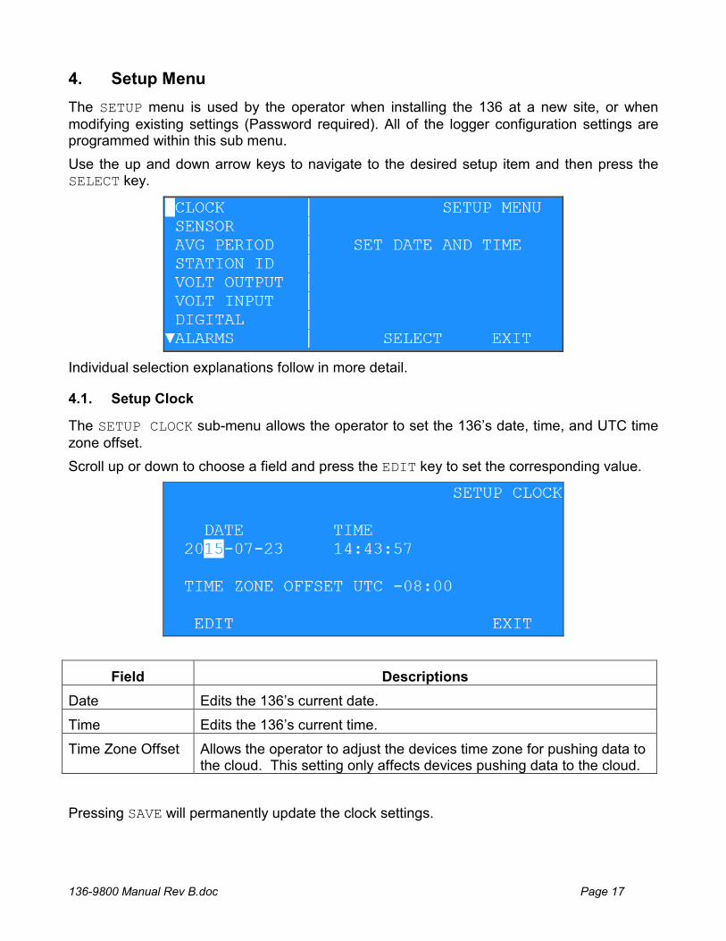
The SETUP menu is used by the operator when installing the 136 at a new site, or when modifying existing settings (Password required). All of the logger configuration settings are programmed within this sub menu.
Use the up and down arrow keys to navigate to the desired setup item and then press the SELECT key.
Individual selection explanations follow in more detail.
4.1. Setup Clock
The SETUP CLOCK sub-menu allows the operator to set the 136’s date, time, and UTC time zone offset.
Scroll up or down to choose a field and press the EDIT key to set the corresponding value.
Field Descriptions
Date Edits the 136’s current date.
Time Edits the 136’s current time.
Time Zone Offset Allows the operator to adjust the devices time zone for pushing data to the cloud. This setting only affects devices pushing data to the cloud.
Pressing SAVE will permanently update the clock settings.
136-9800 Manual Rev B.doc Page 18
Note: It is only necessary to enter the last two digits of the year; this does require that any customer developed software be aware of this two digit method of year indication, and automatically add the 20XX to the year field. The 136 recognizes correct year / leap year information until the year 2050.
4.2. Setup Sensor
4.2.1. Sensor Setup Introduction
The 136 Data logger provides eight analog inputs for logging Meteorological sensor data. These sensors can be connected to the logger as indicated in Appendix D. The 136 comes from the factory pre-configured for your ordered set of sensors.
New sensors connected to the logger must be configured in the logger setup before data can be acquired.
Each channel has a general setup screen for setting the name, units, and source. Within the setup screen is a SCALE hot key that can select a scaling screen for setting measurement specifics.
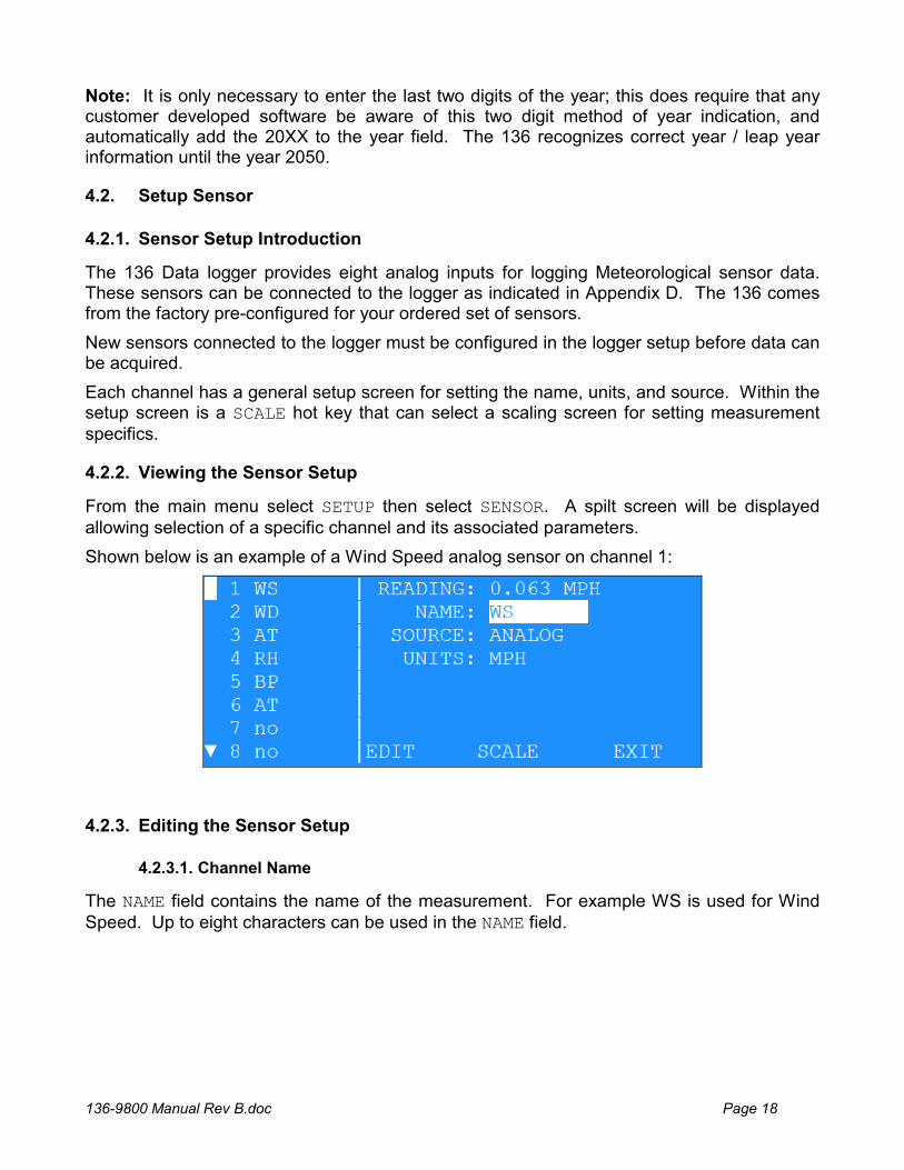
4.2.2. Viewing the Sensor Setup
From the main menu select SETUP then select SENSOR. A spilt screen will be displayed allowing selection of a specific channel and its associated parameters.
Shown below is an example of a Wind Speed analog sensor on channel 1:
4.2.3. Editing the Sensor Setup
The NAME field contains the name of the measurement. For example WS is used for Wind Speed. Up to eight characters can be used in the NAME field.
4.2.3.1. Channel Name
136-9800 Manual Rev B.doc Page 19
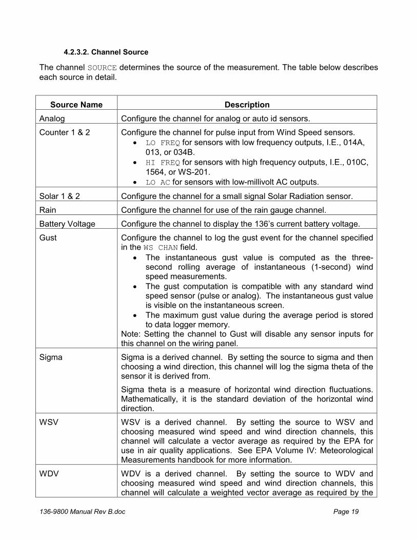
The channel SOURCE determines the source of the measurement. The table below describes each source in detail.
Source Name Description
Analog Configure the channel for analog or auto id sensors.
Counter 1 & 2 Configure the channel for pulse input from Wind Speed sensors. LO FREQ for sensors with low frequency outputs, I.E., 014A,
013, or 034B. HI FREQ for sensors with high frequency outputs, I.E., 010C,
1564, or WS-201. LO AC for sensors with low-millivolt AC outputs.
Solar 1 & 2 Configure the channel for a small signal Solar Radiation sensor.
Rain Configure the channel for use of the rain gauge channel.
Battery Voltage Configure the channel to display the 136’s current battery voltage.
Gust Configure the channel to log the gust event for the channel specified in the WS CHAN field.
The instantaneous gust value is computed as the three-second rolling average of instantaneous (1-second) wind speed measurements.
The gust computation is compatible with any standard wind speed sensor (pulse or analog). The instantaneous gust value is visible on the instantaneous screen.
The maximum gust value during the average period is stored to data logger memory.
Note: Setting the channel to Gust will disable any sensor inputs for this channel on the wiring panel.
Sigma Sigma is a derived channel. By setting the source to sigma and then choosing a wind direction, this channel will log the sigma theta of the sensor it is derived from.
Sigma theta is a measure of horizontal wind direction fluctuations. Mathematically, it is the standard deviation of the horizontal wind direction.
WSV WSV is a derived channel. By setting the source to WSV and choosing measured wind speed and wind direction channels, this channel will calculate a vector average as required by the EPA for use in air quality applications. See EPA Volume IV: Meteorological Measurements handbook for more information.
WDV WDV is a derived channel. By setting the source to WDV and choosing measured wind speed and wind direction channels, this channel will calculate a weighted vector average as required by the
4.2.3.2. Channel Source
136-9800 Manual Rev B.doc Page 20
EPA for use in air quality applications. See EPA Volume IV: Meteorological Measurements handbook for more information.
Min Min is a derived channel. By setting the source to Min and selecting a channel, this channel will always log the minimum value of the derived channel.
Max Max is a derived channel. By setting the source to Max and selecting a channel, this channel will always log the minimum value of the derived channel.
Dew Point Dew Point is a derived channel. By setting the source to Dew Point and choosing a temperature and humidity channel, this channel will always log the dew point calculated between these two channels.
Standard Deviation Standard Deviation is a derived channel. By setting the source to Std Dev and selecting a channel, this channel will always log the calculated standard deviation when the logger is in Data Average mode. Otherwise, for the instantaneous data, it will log the current channel reading.
Delta T Delta T is a derived channel. By setting the source to Delta and selecting two temperature channels, this channel will always log the calculated difference of temperature 1 from temperature 2.
Unused If you do not need 16 channels for your device, operators can set a channel to unused, in which the channel becomes ignored. When a channel is set to unused, it will not be logged.
The UNITS field contains the engineering units of the measurement (example: MPH for Miles Per Hour). Up to six characters are available in the UNITS field.
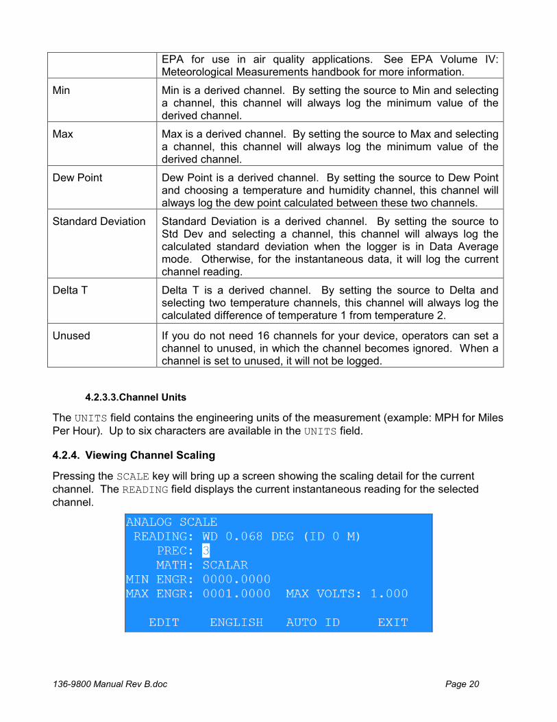
4.2.4. Viewing Channel Scaling
Pressing the SCALE key will bring up a screen showing the scaling detail for the current channel. The READING field displays the current instantaneous reading for the selected channel.
4.2.3.3.Channel Units
136-9800 Manual Rev B.doc Page 21
4.2.5. Set Analog Channel Scaling
These fields are available for scaling the current channel measurement:
PREC: Measurement precision; Number of digits to the right of the decimal point.
MATH: Set the type of measurement as scalar or vector.
MIN ENGR: Engineering units at zero sensor volts.
MAX ENGR: Engineering units at full scale sensor volts.
MAX VOLTS: Full scale output voltage of the sensor.
136-9800 Manual Rev B.doc Page 22
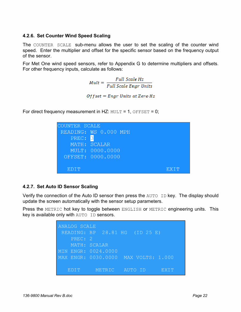
4.2.6. Set Counter Wind Speed Scaling
The COUNTER SCALE sub-menu allows the user to set the scaling of the counter wind speed. Enter the multiplier and offset for the specific sensor based on the frequency output of the sensor.
For Met One wind speed sensors, refer to Appendix G to determine multipliers and offsets. For other frequency inputs, calculate as follows:
For direct frequency measurement in HZ: MULT = 1, OFFSET = 0;
4.2.7. Set Auto ID Sensor Scaling
Verify the connection of the Auto ID sensor then press the AUTO ID key. The display should update the screen automatically with the sensor setup parameters.
Press the METRIC hot key to toggle between ENGLISH or METRIC engineering units. This key is available only with AUTO ID sensors.
ANALOG SCALE READING: BP 28.81 HG (ID 25 E) PREC: 2 MATH: SCALARMIN ENGR: 0024.0000MAX ENGR: 0030.0000 MAX VOLTS: 1.000
EDIT METRIC AUTO ID EXIT
136-9800 Manual Rev B.doc Page 23
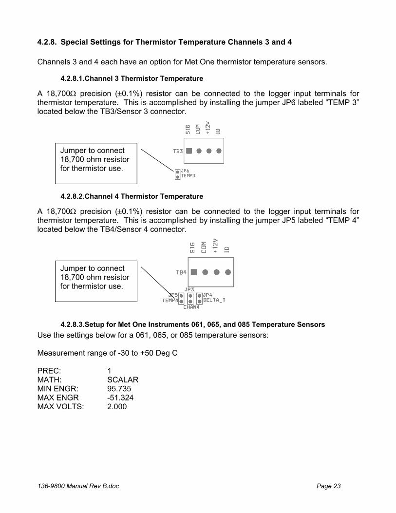
4.2.8. Special Settings for Thermistor Temperature Channels 3 and 4
Channels 3 and 4 each have an option for Met One thermistor temperature sensors.
A 18,700 precision (0.1%) resistor can be connected to the logger input terminals for thermistor temperature. This is accomplished by installing the jumper JP6 labeled “TEMP 3” located below the TB3/Sensor 3 connector.
A 18,700 precision (0.1%) resistor can be connected to the logger input terminals for thermistor temperature. This is accomplished by installing the jumper JP5 labeled “TEMP 4” located below the TB4/Sensor 4 connector.
Use the settings below for a 061, 065, or 085 temperature sensors: Measurement range of -30 to +50 Deg C PREC: 1 MATH: SCALAR MIN ENGR: 95.735 MAX ENGR -51.324 MAX VOLTS: 2.000
4.2.8.1.Channel 3 Thermistor Temperature
4.2.8.2.Channel 4 Thermistor Temperature
4.2.8.3.Setup for Met One Instruments 061, 065, and 085 Temperature Sensors
Jumper to connect 18,700 ohm resistor for thermistor use.
Jumper to connect 18,700 ohm resistor for thermistor use.
136-9800 Manual Rev B.doc Page 24
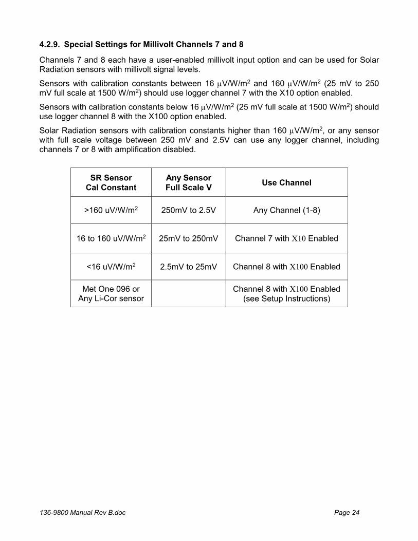
4.2.9. Special Settings for Millivolt Channels 7 and 8
Channels 7 and 8 each have a user-enabled millivolt input option and can be used for Solar Radiation sensors with millivolt signal levels.
Sensors with calibration constants between 16 V/W/m2 and 160 V/W/m2 (25 mV to 250 mV full scale at 1500 W/m2) should use logger channel 7 with the X10 option enabled.
Sensors with calibration constants below 16 V/W/m2 (25 mV full scale at 1500 W/m2) should use logger channel 8 with the X100 option enabled.
Solar Radiation sensors with calibration constants higher than 160 V/W/m2, or any sensor with full scale voltage between 250 mV and 2.5V can use any logger channel, including channels 7 or 8 with amplification disabled.
SR Sensor Cal Constant
Any Sensor Full Scale V
Use Channel
>160 uV/W/m2 250mV to 2.5V Any Channel (1-8)
16 to 160 uV/W/m2 25mV to 250mV Channel 7 with X10 Enabled
<16 uV/W/m2 2.5mV to 25mV Channel 8 with X100 Enabled
Met One 096 or Any Li-Cor sensor
Channel 8 with X100 Enabled
(see Setup Instructions)
136-9800 Manual Rev B.doc Page 25
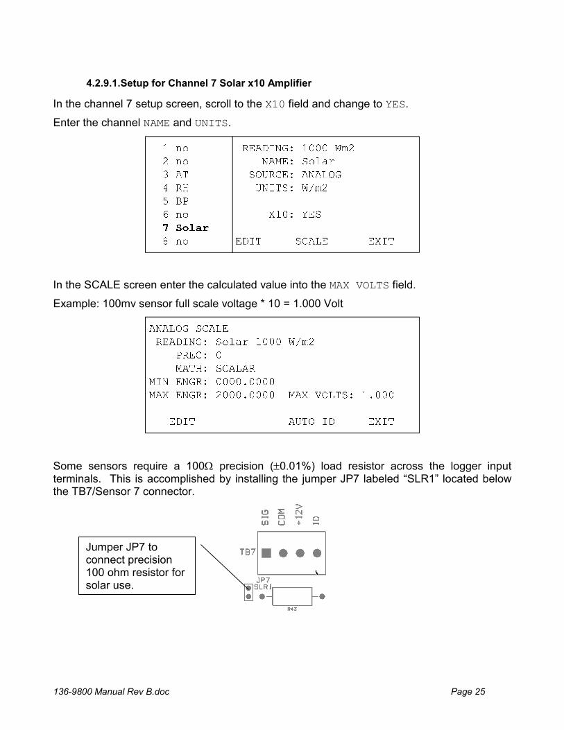
In the channel 7 setup screen, scroll to the X10 field and change to YES.
Enter the channel NAME and UNITS.
In the SCALE screen enter the calculated value into the MAX VOLTS field.
Example: 100mv sensor full scale voltage * 10 = 1.000 Volt
Some sensors require a 100 precision (0.01%) load resistor across the logger input terminals. This is accomplished by installing the jumper JP7 labeled “SLR1” located below the TB7/Sensor 7 connector.
4.2.9.1.Setup for Channel 7 Solar x10 Amplifier
Jumper JP7 to connect precision 100 ohm resistor for solar use.
136-9800 Manual Rev B.doc Page 26
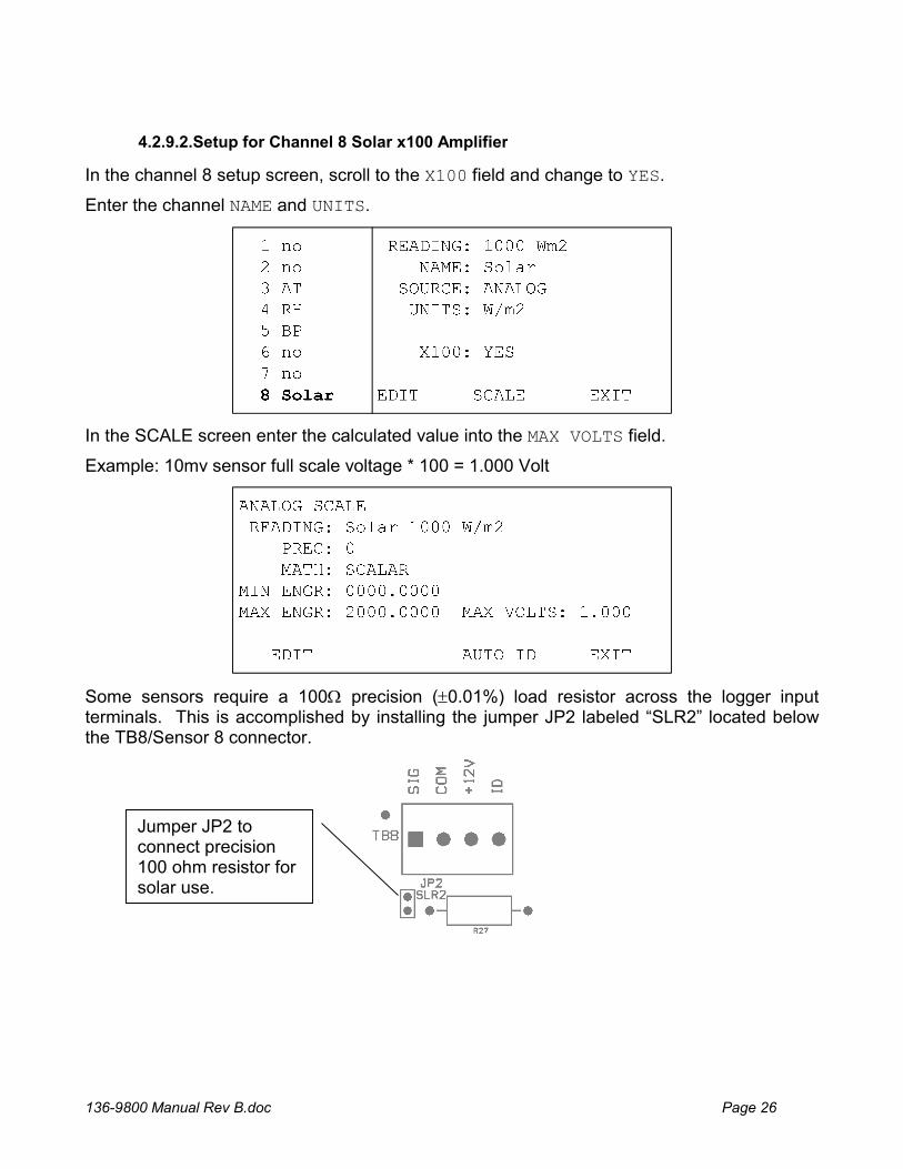
In the channel 8 setup screen, scroll to the X100 field and change to YES.
Enter the channel NAME and UNITS.
In the SCALE screen enter the calculated value into the MAX VOLTS field.
Example: 10mv sensor full scale voltage * 100 = 1.000 Volt
Some sensors require a 100 precision (0.01%) load resistor across the logger input terminals. This is accomplished by installing the jumper JP2 labeled “SLR2” located below the TB8/Sensor 8 connector.
4.2.9.2.Setup for Channel 8 Solar x100 Amplifier
Jumper JP2 to connect precision 100 ohm resistor for solar use.
136-9800 Manual Rev B.doc Page 27
This sensor has a current output and requires a load resistor to convert the signal to a voltage for the logger measurement. See the setup for Channel 8 section above for resistor installation instructions.
The Calibration Constant on the calibration certificate is stated in units of A/KW/m2 and must be converted to units of V/W/m2 as follows. This calculation is based on the use of a 100 load resistor.
V/W/m2 = A/KW/m2 / 10 (or) CalConstnew = CalConstcert / 10
Example: If the Li-Cor calibration certificate shows a calibration constant of 89.2 A/KW/m2, then the conversion is:
CalConstnew = CalConstcert / 10 = 89.2 / 10 = 8.92 V/W/m2
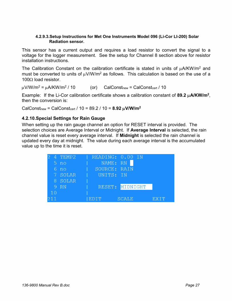
4.2.10.Special Settings for Rain Gauge
When setting up the rain gauge channel an option for RESET interval is provided. The selection choices are Average Interval or Midnight. If Average Interval is selected, the rain channel value is reset every average interval. If Midnight is selected the rain channel is updated every day at midnight. The value during each average interval is the accumulated value up to the time it is reset.
4.2.9.3.Setup Instructions for Met One Instruments Model 096 (Li-Cor LI-200) Solar Radiation sensor.
136-9800 Manual Rev B.doc Page 28
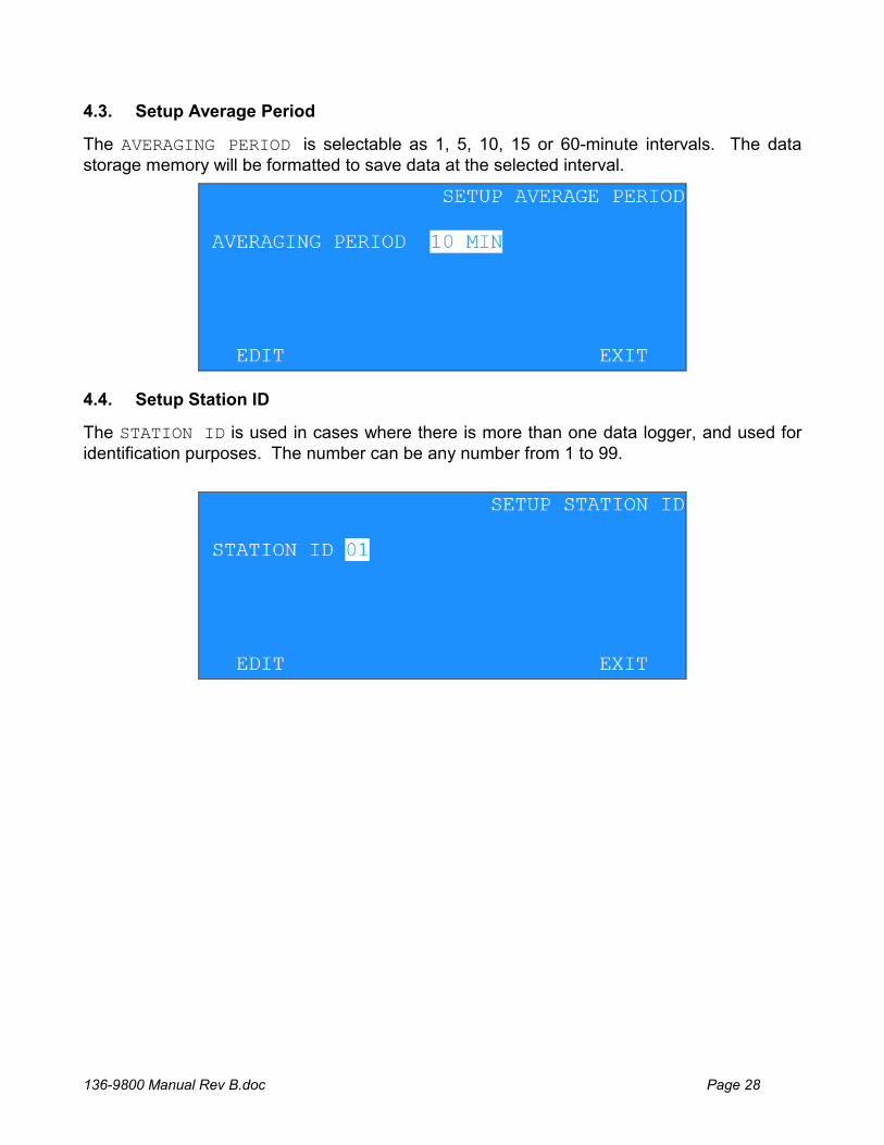
4.3. Setup Average Period
The AVERAGING PERIOD is selectable as 1, 5, 10, 15 or 60-minute intervals. The data storage memory will be formatted to save data at the selected interval.
4.4. Setup Station ID
The STATION ID is used in cases where there is more than one data logger, and used for identification purposes. The number can be any number from 1 to 99.
136-9800 Manual Rev B.doc Page 29
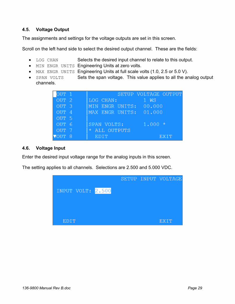
4.5. Voltage Output
The assignments and settings for the voltage outputs are set in this screen. Scroll on the left hand side to select the desired output channel. These are the fields:
LOG CHAN Selects the desired input channel to relate to this output.
MIN ENGR UNITS Engineering Units at zero volts.
MAX ENGR UNITS Engineering Units at full scale volts (1.0, 2.5 or 5.0 V).
SPAN VOLTS Sets the span voltage. This value applies to all the analog output channels.
4.6. Voltage Input
Enter the desired input voltage range for the analog inputs in this screen. The setting applies to all channels. Selections are 2.500 and 5.000 VDC.
136-9800 Manual Rev B.doc Page 30
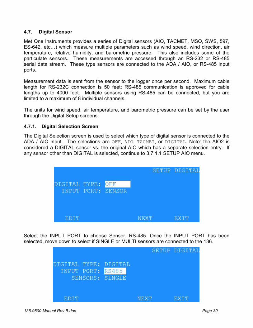
4.7. Digital Sensor
Met One Instruments provides a series of Digital sensors (AIO, TACMET, MSO, SWS, 597, ES-642, etc…) which measure multiple parameters such as wind speed, wind direction, air temperature, relative humidity, and barometric pressure. This also includes some of the particulate sensors. These measurements are accessed through an RS-232 or RS-485 serial data stream. These type sensors are connected to the ADA / AIO, or RS-485 input ports. Measurement data is sent from the sensor to the logger once per second. Maximum cable length for RS-232C connection is 50 feet; RS-485 communication is approved for cable lengths up to 4000 feet. Multiple sensors using RS-485 can be connected, but you are limited to a maximum of 8 individual channels. The units for wind speed, air temperature, and barometric pressure can be set by the user through the Digital Setup screens.
4.7.1. Digital Selection Screen
The Digital Selection screen is used to select which type of digital sensor is connected to the ADA / AIO input. The selections are OFF, AIO, TACMET, or DIGITAL. Note: the AIO2 is considered a DIGITAL sensor vs. the original AIO which has a separate selection entry. If any sensor other than DIGITAL is selected, continue to 3.7.1.1 SETUP AIO menu.
Select the INPUT PORT to choose Sensor, RS-485. Once the INPUT PORT has been selected, move down to select if SINGLE or MULTI sensors are connected to the 136.
136-9800 Manual Rev B.doc Page 31
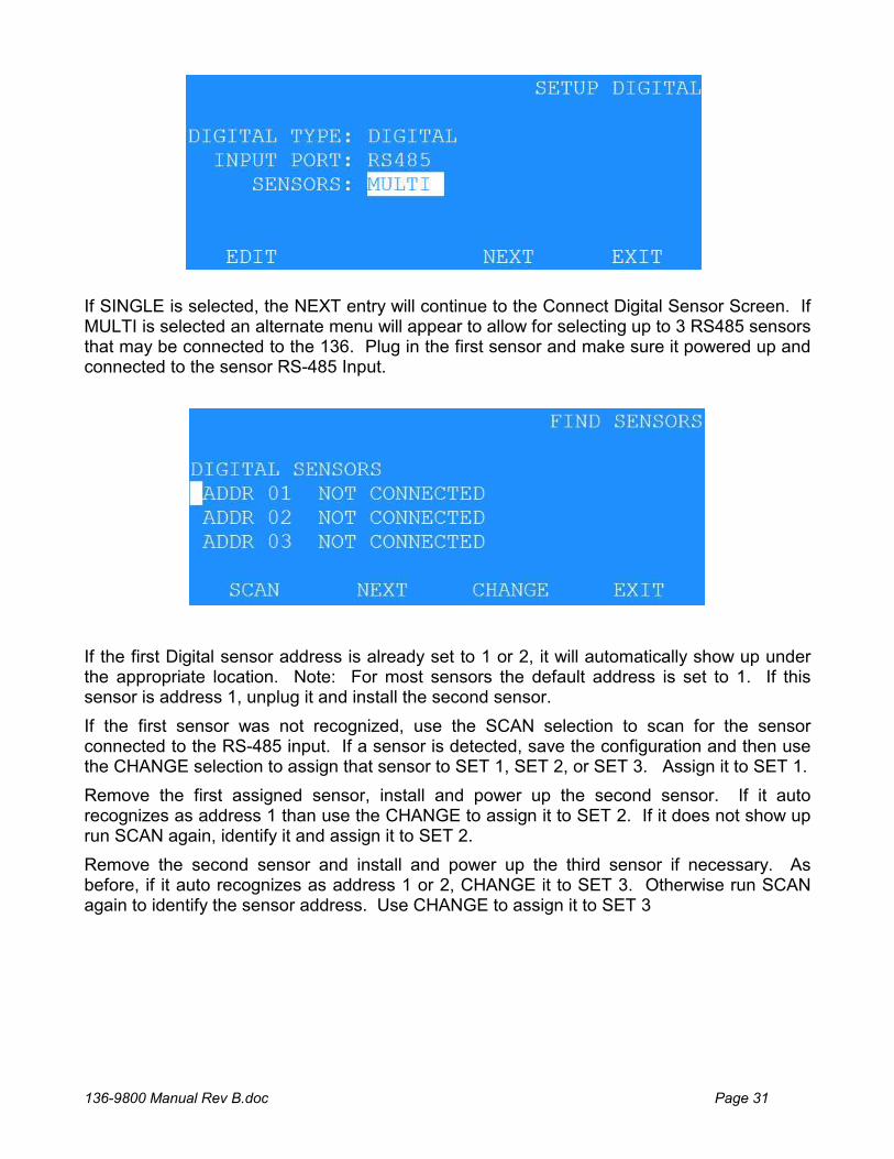
If SINGLE is selected, the NEXT entry will continue to the Connect Digital Sensor Screen. If MULTI is selected an alternate menu will appear to allow for selecting up to 3 RS485 sensors that may be connected to the 136. Plug in the first sensor and make sure it powered up and connected to the sensor RS-485 Input.
If the first Digital sensor address is already set to 1 or 2, it will automatically show up under the appropriate location. Note: For most sensors the default address is set to 1. If this sensor is address 1, unplug it and install the second sensor.
If the first sensor was not recognized, use the SCAN selection to scan for the sensor connected to the RS-485 input. If a sensor is detected, save the configuration and then use the CHANGE selection to assign that sensor to SET 1, SET 2, or SET 3. Assign it to SET 1.
Remove the first assigned sensor, install and power up the second sensor. If it auto recognizes as address 1 than use the CHANGE to assign it to SET 2. If it does not show up run SCAN again, identify it and assign it to SET 2.
Remove the second sensor and install and power up the third sensor if necessary. As before, if it auto recognizes as address 1 or 2, CHANGE it to SET 3. Otherwise run SCAN again to identify the sensor address. Use CHANGE to assign it to SET 3
136-9800 Manual Rev B.doc Page 32
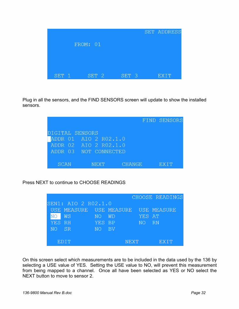
Plug in all the sensors, and the FIND SENSORS screen will update to show the installed sensors.
Press NEXT to continue to CHOOSE READINGS
On this screen select which measurements are to be included in the data used by the 136 by selecting a USE value of YES. Setting the USE value to NO, will prevent this measurement from being mapped to a channel. Once all have been selected as YES or NO select the NEXT button to move to sensor 2.
136-9800 Manual Rev B.doc Page 33
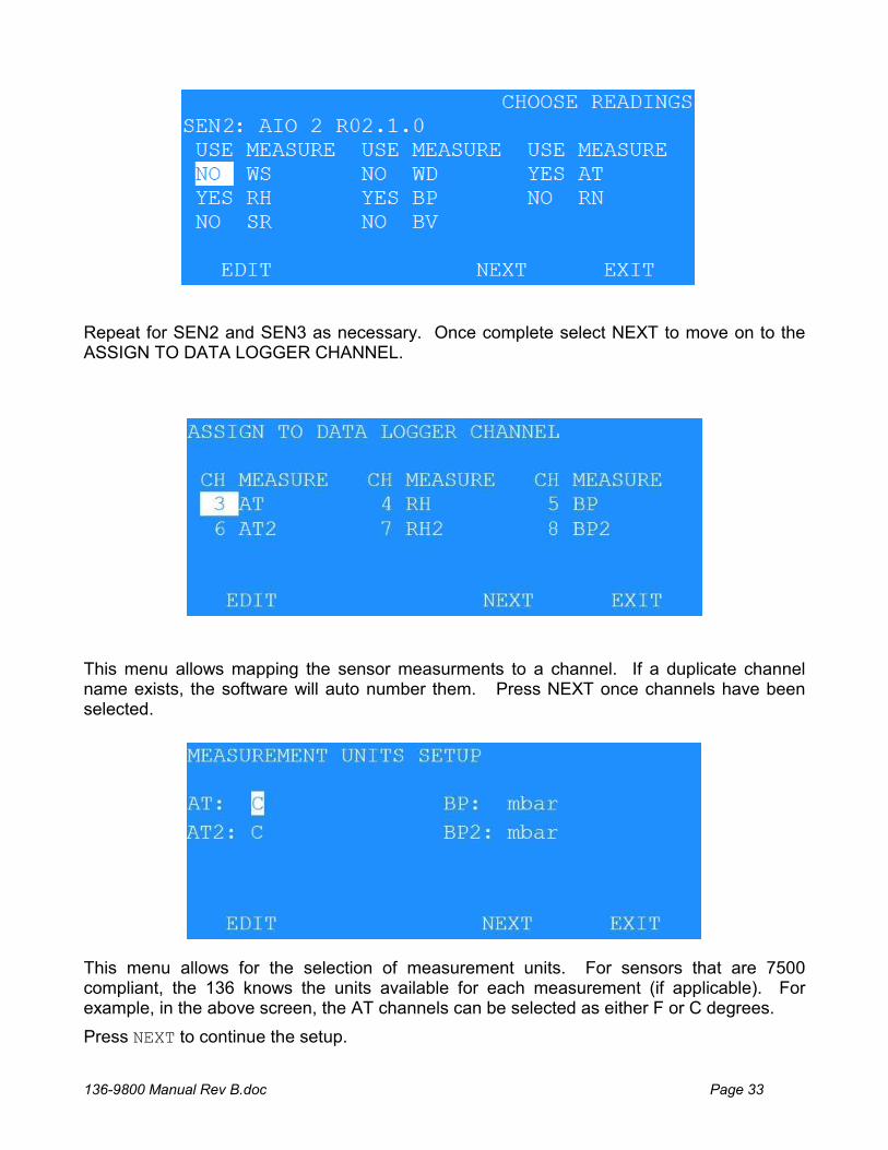
Repeat for SEN2 and SEN3 as necessary. Once complete select NEXT to move on to the ASSIGN TO DATA LOGGER CHANNEL.
This menu allows mapping the sensor measurments to a channel. If a duplicate channel name exists, the software will auto number them. Press NEXT once channels have been selected.
This menu allows for the selection of measurement units. For sensors that are 7500 compliant, the 136 knows the units available for each measurement (if applicable). For example, in the above screen, the AT channels can be selected as either F or C degrees.
Press NEXT to continue the setup.
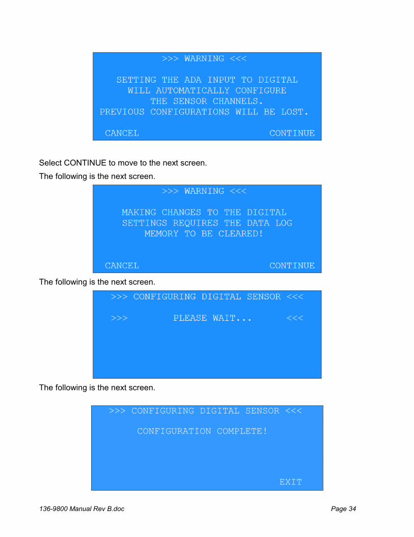
136-9800 Manual Rev B.doc Page 34
Select CONTINUE to move to the next screen.
The following is the next screen.
The following is the next screen.
The following is the next screen.
>>> CONFIGURING DIGITAL SENSOR <<< CONFIGURATION COMPLETE! EXIT
136-9800 Manual Rev B.doc Page 35
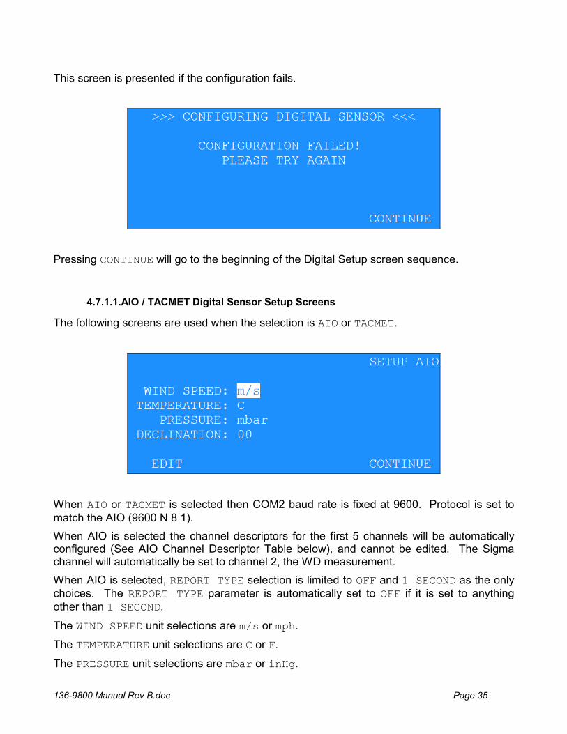
This screen is presented if the configuration fails.
Pressing CONTINUE will go to the beginning of the Digital Setup screen sequence.
The following screens are used when the selection is AIO or TACMET.
When AIO or TACMET is selected then COM2 baud rate is fixed at 9600. Protocol is set to match the AIO (9600 N 8 1).
When AIO is selected the channel descriptors for the first 5 channels will be automatically configured (See AIO Channel Descriptor Table below), and cannot be edited. The Sigma channel will automatically be set to channel 2, the WD measurement.
When AIO is selected, REPORT TYPE selection is limited to OFF and 1 SECOND as the only choices. The REPORT TYPE parameter is automatically set to OFF if it is set to anything other than 1 SECOND.
The WIND SPEED unit selections are m/s or mph.
The TEMPERATURE unit selections are C or F.
The PRESSURE unit selections are mbar or inHg.
4.7.1.1.AIO / TACMET Digital Sensor Setup Screens
136-9800 Manual Rev B.doc Page 36
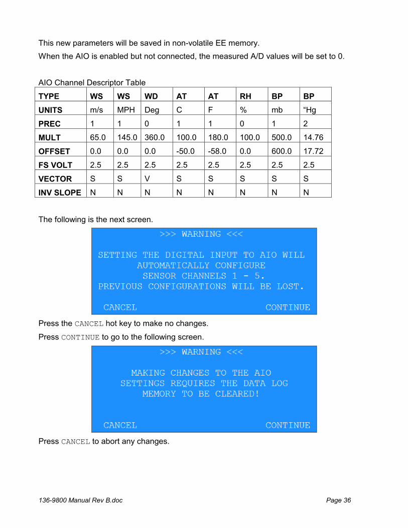
This new parameters will be saved in non-volatile EE memory.
When the AIO is enabled but not connected, the measured A/D values will be set to 0.
AIO Channel Descriptor Table
TYPE WS WS WD AT AT RH BP BP
UNITS m/s MPH Deg C F % mb “Hg
PREC 1 1 0 1 1 0 1 2
MULT 65.0 145.0 360.0 100.0 180.0 100.0 500.0 14.76
OFFSET 0.0 0.0 0.0 -50.0 -58.0 0.0 600.0 17.72
FS VOLT 2.5 2.5 2.5 2.5 2.5 2.5 2.5 2.5
VECTOR S S V S S S S S
INV SLOPE N N N N N N N N
The following is the next screen.
Press the CANCEL hot key to make no changes.
Press CONTINUE to go to the following screen.
Press CANCEL to abort any changes.
136-9800 Manual Rev B.doc Page 37
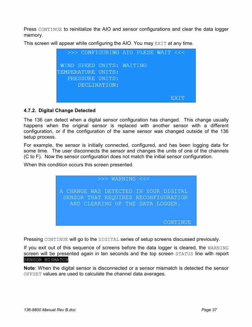
Press CONTINUE to reinitialize the AIO and sensor configurations and clear the data logger memory.
This screen will appear while configuring the AIO. You may EXIT at any time.
4.7.2. Digital Change Detected
The 136 can detect when a digital sensor configuration has changed. This change usually happens when the original sensor is replaced with another sensor with a different configuration, or if the configuration of the same sensor was changed outside of the 136 setup process.
For example, the sensor is initially connected, configured, and has been logging data for some time. The user disconnects the sensor and changes the units of one of the channels (C to F). Now the sensor configuration does not match the initial sensor configuration.
When this condition occurs this screen presented.
>>> WARNING <<< A CHANGE WAS DETECTED IN YOUR DIGITAL SENSOR THAT REQUIRES RECONFIGURATION AND CLEARING OF THE DATA LOGGER. CONTINUE
Pressing CONTINUE will go to the DIGITAL series of setup screens discussed previously.
If you exit out of this sequence of screens before the data logger is cleared, the WARNING screen will be presented again in ten seconds and the top screen STATUS line with report SENSOR MISMATCH.
Note: When the digital sensor is disconnected or a sensor mismatch is detected the sensor OFFSET values are used to calculate the channel data averages.
136-9800 Manual Rev B.doc Page 38
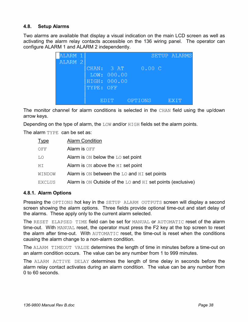
4.8. Setup Alarms
Two alarms are available that display a visual indication on the main LCD screen as well as activating the alarm relay contacts accessible on the 136 wiring panel. The operator can configure ALARM 1 and ALARM 2 independently.
The monitor channel for alarm conditions is selected in the CHAN field using the up/down arrow keys.
Depending on the type of alarm, the LOW and/or HIGH fields set the alarm points.
The alarm TYPE can be set as:
Type Alarm Condition
OFF Alarm is OFF
LO Alarm is ON below the LO set point
HI Alarm is ON above the HI set point
WINDOW Alarm is ON between the LO and HI set points
EXCLUS Alarm is ON Outside of the LO and HI set points (exclusive)
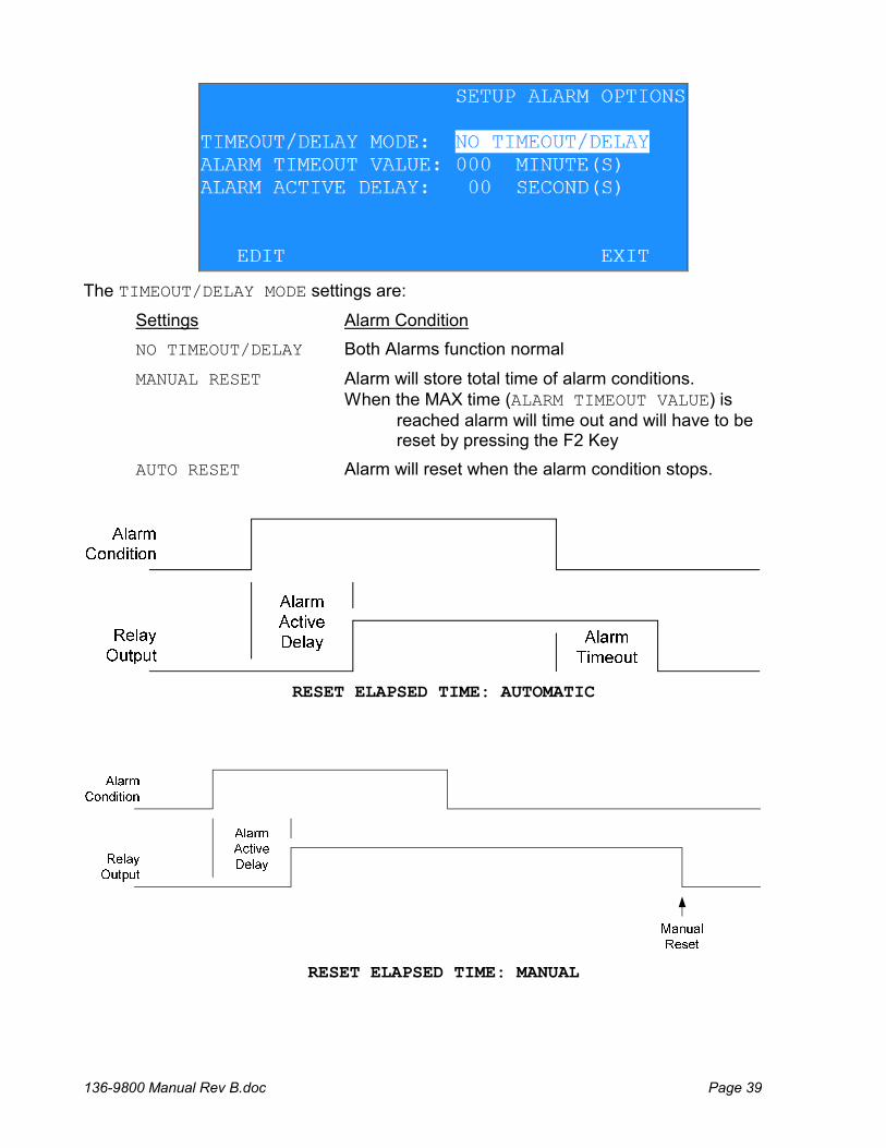
4.8.1. Alarm Options
Pressing the OPTIONS hot key in the SETUP ALARM OUTPUTS screen will display a second screen showing the alarm options. Three fields provide optional time-out and start delay of the alarms. These apply only to the current alarm selected.
The RESET ELAPSED TIME field can be set for MANUAL or AUTOMATIC reset of the alarm time-out. With MANUAL reset, the operator must press the F2 key at the top screen to reset the alarm after time-out. With AUTOMATIC reset, the time-out is reset when the conditions causing the alarm change to a non-alarm condition.
The ALARM TIMEOUT VALUE determines the length of time in minutes before a time-out on an alarm condition occurs. The value can be any number from 1 to 999 minutes.
The ALARM ACTIVE DELAY determines the length of time delay in seconds before the alarm relay contact activates during an alarm condition. The value can be any number from 0 to 60 seconds.
136-9800 Manual Rev B.doc Page 39
The TIMEOUT/DELAY MODE settings are:
Settings Alarm Condition
NO TIMEOUT/DELAY Both Alarms function normal
MANUAL RESET Alarm will store total time of alarm conditions. When the MAX time (ALARM TIMEOUT VALUE) is reached alarm will time out and will have to be reset by pressing the F2 Key
AUTO RESET Alarm will reset when the alarm condition stops.
RESET ELAPSED TIME: AUTOMATIC
RESET ELAPSED TIME: MANUAL
136-9800 Manual Rev B.doc Page 40
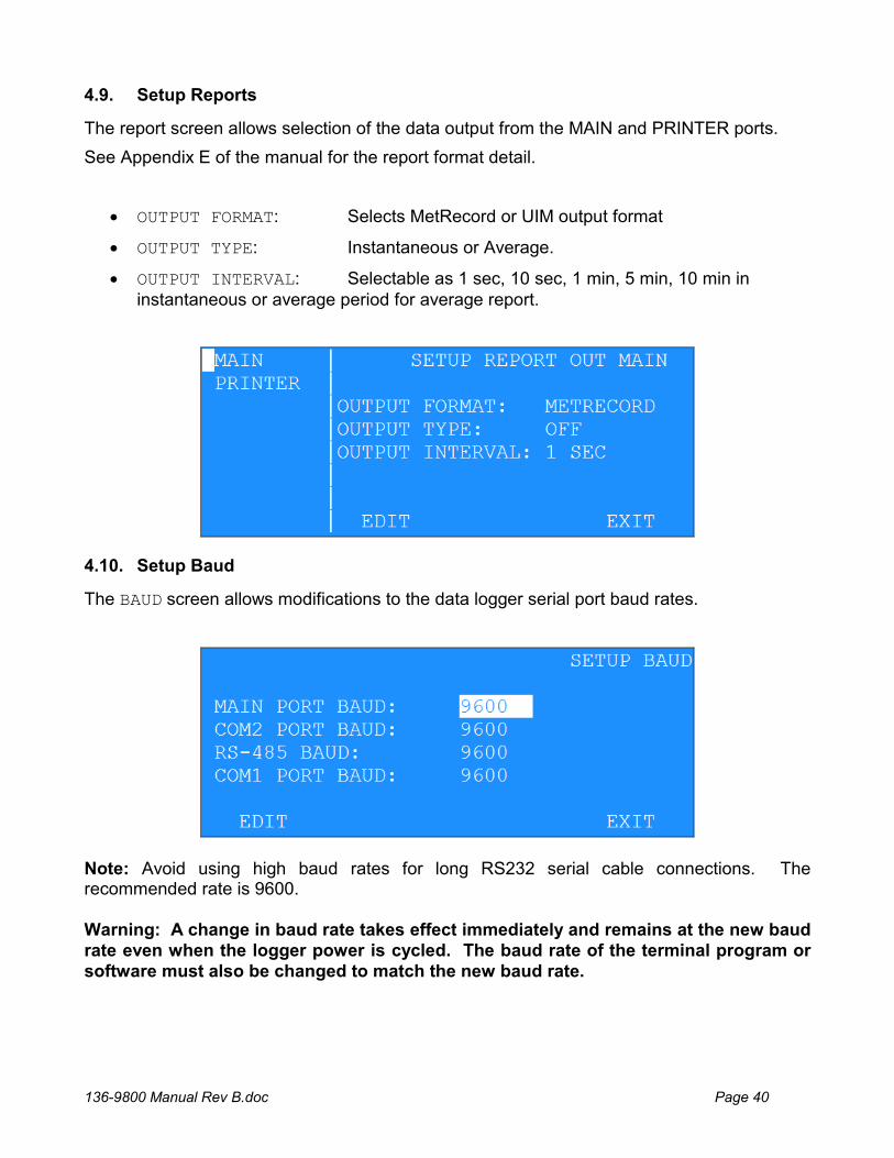
4.9. Setup Reports
The report screen allows selection of the data output from the MAIN and PRINTER ports.
See Appendix E of the manual for the report format detail.
OUTPUT FORMAT: Selects MetRecord or UIM output format
OUTPUT TYPE: Instantaneous or Average.
OUTPUT INTERVAL: Selectable as 1 sec, 10 sec, 1 min, 5 min, 10 min in instantaneous or average period for average report.
4.10. Setup Baud
The BAUD screen allows modifications to the data logger serial port baud rates.
Note: Avoid using high baud rates for long RS232 serial cable connections. The recommended rate is 9600. Warning: A change in baud rate takes effect immediately and remains at the new baud rate even when the logger power is cycled. The baud rate of the terminal program or software must also be changed to match the new baud rate.
136-9800 Manual Rev B.doc Page 41
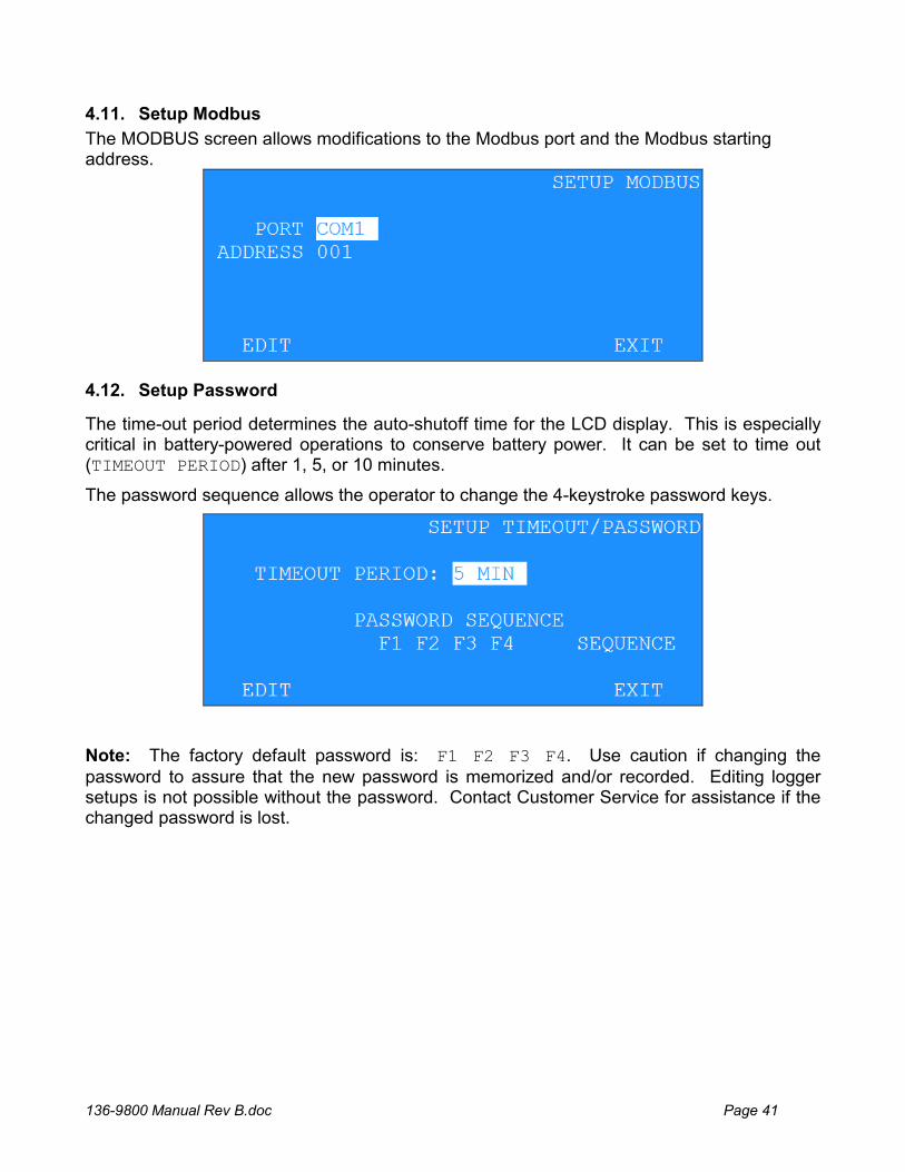
4.11. Setup Modbus
The MODBUS screen allows modifications to the Modbus port and the Modbus starting address.
4.12. Setup Password
The time-out period determines the auto-shutoff time for the LCD display. This is especially critical in battery-powered operations to conserve battery power. It can be set to time out (TIMEOUT PERIOD) after 1, 5, or 10 minutes.
The password sequence allows the operator to change the 4-keystroke password keys.
Note: The factory default password is: F1 F2 F3 F4. Use caution if changing the password to assure that the new password is memorized and/or recorded. Editing logger setups is not possible without the password. Contact Customer Service for assistance if the changed password is lost.
136-9800 Manual Rev B.doc Page 42
4.13. Setup Communications Screen
This screen allows the operator to make changes to the internet/communication settings of the 136. The table below explains each settings.
Field Description Cloud Modem If the 136 came with a cell modem, this option allows the user to pick the
type of modem. Current options are NONE, GSM, and CDMA. Modem Port Allows the user to set which port the modem will use to talk with the 136.
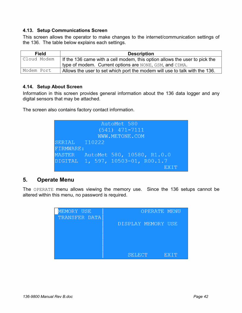
4.14. Setup About Screen
Information in this screen provides general information about the 136 data logger and any digital sensors that may be attached. The screen also contains factory contact information.
5. Operate Menu
The OPERATE menu allows viewing the memory use. Since the 136 setups cannot be altered within this menu, no password is required.
136-9800 Manual Rev B.doc Page 43
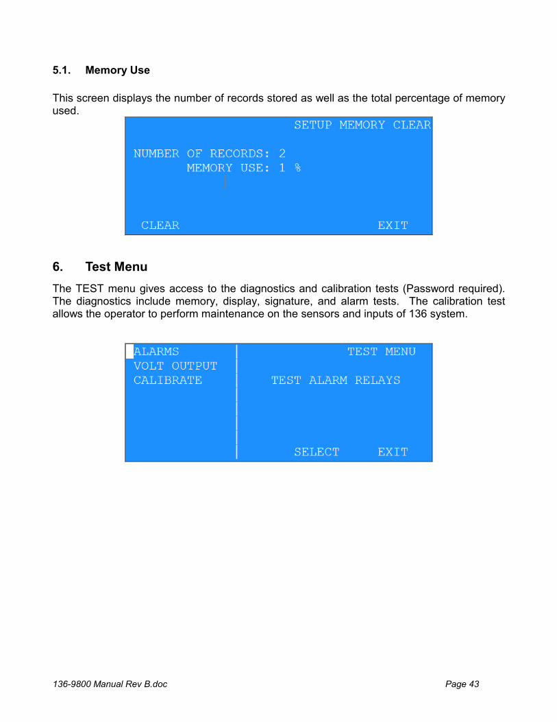
5.1. Memory Use
This screen displays the number of records stored as well as the total percentage of memory used.
6. Test Menu
The TEST menu gives access to the diagnostics and calibration tests (Password required). The diagnostics include memory, display, signature, and alarm tests. The calibration test allows the operator to perform maintenance on the sensors and inputs of 136 system.
136-9800 Manual Rev B.doc Page 44
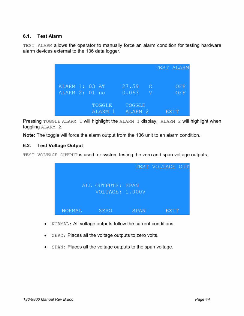
6.1. Test Alarm
TEST ALARM allows the operator to manually force an alarm condition for testing hardware alarm devices external to the 136 data logger.
Pressing TOGGLE ALARM 1 will highlight the ALARM 1 display. ALARM 2 will highlight when toggling ALARM 2.
Note: The toggle will force the alarm output from the 136 unit to an alarm condition.
6.2. Test Voltage Output
TEST VOLTAGE OUTPUT is used for system testing the zero and span voltage outputs.
NORMAL: All voltage outputs follow the current conditions.
ZERO: Places all the voltage outputs to zero volts.
SPAN: Places all the voltage outputs to the span voltage.
136-9800 Manual Rev B.doc Page 45
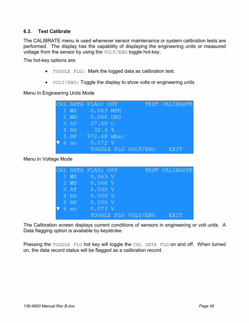
6.3. Test Calibrate
The CALIBRATE menu is used whenever sensor maintenance or system calibration tests are performed. The display has the capability of displaying the engineering units or measured voltage from the sensor by using the VOLT/ENG toggle hot-key.
The hot-key options are:
TOGGLE FLG: Mark the logged data as calibration test.
VOLT/ENG: Toggle the display to show volts or engineering units
Menu in Engineering Units Mode
Menu in Voltage Mode
The Calibration screen displays current conditions of sensors in engineering or volt units. A Data flagging option is available by keystroke.
Pressing the TOGGLE FLG hot key will toggle the CAL DATA FLG on and off. When turned on, the data record status will be flagged as a calibration record.
136-9800 Manual Rev B.doc Page 46
7. RS232 Communication
7.1. RS232 Port Description
An RS-232 port is provided for external communications to the 136 unit. Access to the 136 is menu driven; allowing any DOS, WINDOWS, or MAC based terminal communication software to communicate with the 136 unit.
Other features of the RS-232 port allow setting the Date and Time, erasing the 136 memory, binary downloading of data, and the ability to view the current 136 setups.
To enable remote computers to communicate with the data logger series, an optional modem may be installed. This device requires a dedicated dial-up telephone line.
Note: It is assumed that the installer is familiar with the operation of and interfacing of the RS232 port of the computer.
Connect the appropriate voltage rated AC power adapter to the 136 unit and Local AC power. Power the computer and start the terminal, Air Plus 5 or Comet software. The default settings for RS232 communications are:
9600 Baud
8 Bit data
1 Stop bit
No parity
Consult the manual for the terminal, Air Plus 5 or Comet software to set and verify these settings.
7.2. USB
WARNING: The USB serial drivers, located on the Comet CD (P/N 80248) must be installed on the host computer prior to attempting to communicate with the 136. See Appendix I for installation instructions.
NOTE: The Main RS-232 port and the USB port should not have cables plugged in at the same time as they are the same Main communication port.
If simultaneous RS-232 and USB connections are needed, use the RS-232 Printer or Extra ports along with the USB.
The USB serial drivers allow the host computer to communicate to the 136 using the Air Plus 5, Comet, or any standard serial communications program. The USB connection is a virtual RS-232 connection and as such must be set to match the RS-232 settings of the 136. Refer to Section 7.1 for information about setting the communication port settings.
The 136 comes with a standard male type A to Male type B USB cable for connection to the PC. Connect this USB cable (P/N 500784) between the 136 and the host computer USB port.
136-9800 Manual Rev B.doc Page 47
7.3. Modem Option
Operation of the modem option is performed by using a second internal or external modem at the computer or terminal. The 136 modem will automatically answer when called. Verify the operation as outlined in section 4.0. If the 136 modem does not answer or communicate, check the cabling.
To verify the RS232 connection to the 136 unit, press the <Enter> key a minimum of 3 times. An asterisk character (*) should be seen on the screen (If not seen, check the cabling and communications settings). To prevent modem line noise from activating the modem, it requires three <enter> commands to recognize a connection.
7.4. Cloud Option
The 136 has a cloud option in which a pre-configured modem will be sent with the unit. The 136 will send the data to the cloud and users may visit their webpage created by Met One to view their secure data. For more information please contact a sales person by e-mailing [email protected] or giving us a call at 541-471-7111. See Section 3 for detailed communication configuration settings.
136-9800 Manual Rev B.doc Page 48
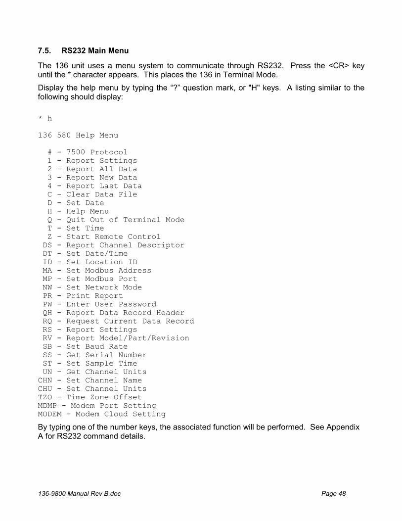
7.5. RS232 Main Menu
The 136 unit uses a menu system to communicate through RS232. Press the <CR> key until the * character appears. This places the 136 in Terminal Mode.
Display the help menu by typing the “?” question mark, or "H" keys. A listing similar to the following should display:
* h 136 580 Help Menu # - 7500 Protocol 1 - Report Settings 2 - Report All Data 3 - Report New Data 4 - Report Last Data C - Clear Data File D - Set Date H - Help Menu Q - Quit Out of Terminal Mode T - Set Time Z - Start Remote Control DS - Report Channel Descriptor DT - Set Date/Time ID - Set Location ID MA - Set Modbus Address MP - Set Modbus Port NW - Set Network Mode PR - Print Report PW - Enter User Password QH - Report Data Record Header RQ - Request Current Data Record RS - Report Settings RV - Report Model/Part/Revision SB - Set Baud Rate SS - Get Serial Number ST - Set Sample Time UN - Get Channel Units CHN - Set Channel Name CHU - Set Channel Units TZO - Time Zone Offset MDMP - Modem Port Setting MODEM - Modem Cloud Setting
By typing one of the number keys, the associated function will be performed. See Appendix A for RS232 command details.
136-9800 Manual Rev B.doc Page 49
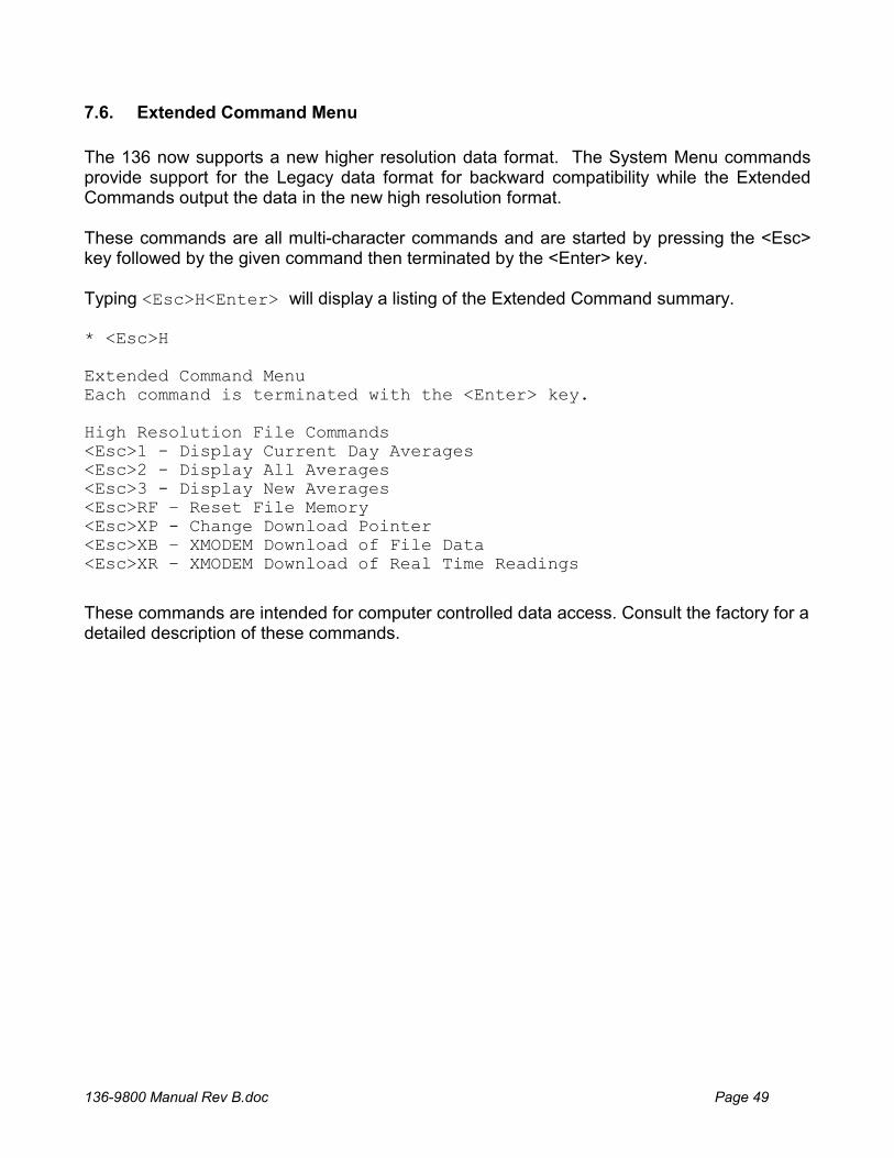
7.6. Extended Command Menu
The 136 now supports a new higher resolution data format. The System Menu commands provide support for the Legacy data format for backward compatibility while the Extended Commands output the data in the new high resolution format. These commands are all multi-character commands and are started by pressing the <Esc> key followed by the given command then terminated by the <Enter> key. Typing <Esc>H<Enter> will display a listing of the Extended Command summary. * <Esc>H Extended Command Menu Each command is terminated with the <Enter> key. High Resolution File Commands <Esc>1 - Display Current Day Averages <Esc>2 - Display All Averages <Esc>3 - Display New Averages <Esc>RF – Reset File Memory <Esc>XP - Change Download Pointer <Esc>XB – XMODEM Download of File Data <Esc>XR – XMODEM Download of Real Time Readings
These commands are intended for computer controlled data access. Consult the factory for a detailed description of these commands.
136-9800 Manual Rev B.doc Page 50
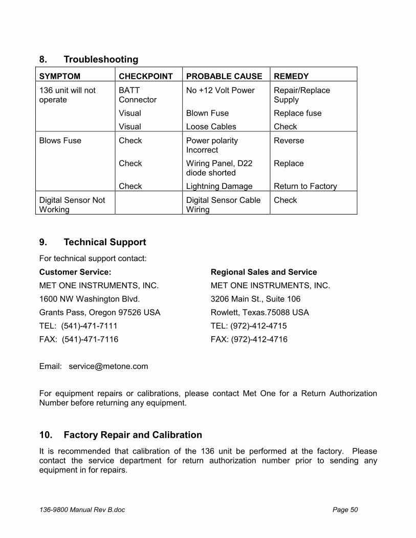
8. Troubleshooting
SYMPTOM CHECKPOINT PROBABLE CAUSE REMEDY
136 unit will not operate
BATT Connector
No +12 Volt Power Repair/Replace Supply
Visual Blown Fuse Replace fuse
Visual Loose Cables Check
Blows Fuse Check Power polarity Incorrect
Reverse
Check Wiring Panel, D22 diode shorted
Replace
Check Lightning Damage Return to Factory
Digital Sensor Not Working
Digital Sensor Cable Wiring
Check
9. Technical Support
For technical support contact:
Customer Service: Regional Sales and Service
MET ONE INSTRUMENTS, INC. MET ONE INSTRUMENTS, INC.
1600 NW Washington Blvd. 3206 Main St., Suite 106
Grants Pass, Oregon 97526 USA Rowlett, Texas.75088 USA
TEL: (541)-471-7111 TEL: (972)-412-4715
FAX: (541)-471-7116 FAX: (972)-412-4716
Email: [email protected]
For equipment repairs or calibrations, please contact Met One for a Return Authorization Number before returning any equipment.
10. Factory Repair and Calibration
It is recommended that calibration of the 136 unit be performed at the factory. Please contact the service department for return authorization number prior to sending any equipment in for repairs.
136-9800 Manual Rev B.doc Page 51
11. Appendices
11.1. Appendix A – RS232 Commands
Note: To stop an operation in process from executing, press the <CR> key.
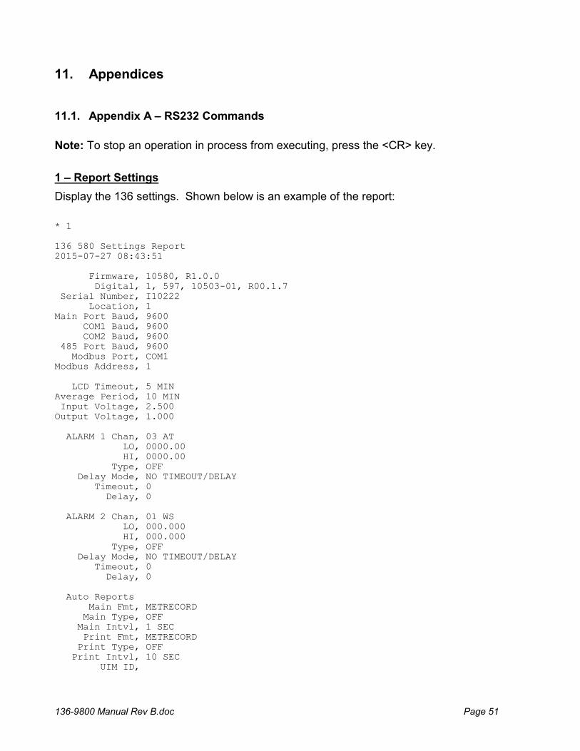
1 – Report Settings
Display the 136 settings. Shown below is an example of the report:
* 1 136 580 Settings Report 2015-07-27 08:43:51 Firmware, 10580, R1.0.0 Digital, 1, 597, 10503-01, R00.1.7 Serial Number, I10222 Location, 1 Main Port Baud, 9600 COM1 Baud, 9600 COM2 Baud, 9600 485 Port Baud, 9600 Modbus Port, COM1 Modbus Address, 1 LCD Timeout, 5 MIN Average Period, 10 MIN Input Voltage, 2.500 Output Voltage, 1.000 ALARM 1 Chan, 03 AT LO, 0000.00 HI, 0000.00 Type, OFF Delay Mode, NO TIMEOUT/DELAY Timeout, 0 Delay, 0 ALARM 2 Chan, 01 WS LO, 000.000 HI, 000.000 Type, OFF Delay Mode, NO TIMEOUT/DELAY Timeout, 0 Delay, 0 Auto Reports Main Fmt, METRECORD Main Type, OFF Main Intvl, 1 SEC Print Fmt, METRECORD Print Type, OFF Print Intvl, 10 SEC UIM ID,
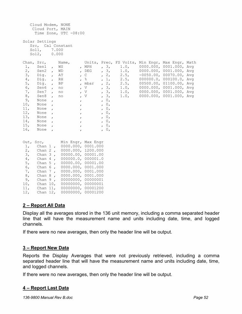
136-9800 Manual Rev B.doc Page 52
Cloud Modem, NONE Cloud Port, MAIN Time Zone, UTC -08:00 Solar Settings Src, Cal Constant Sol1, 7.000 Sol2, 0.000 Chan, Src, Name, Units, Prec, FS Volts, Min Engr, Max Engr, Math 1, Sen1 , WS , MPH , 3, 1.0, 0000.000, 0001.000, Avg 2, Sen2 , WD , DEG , 3, 1.0, 0000.000, 0001.000, Avg 3, Dig. , AT , C , 2, 2.5, -0050.00, 00070.00, Avg 4, Dig. , RH , % , 1, 2.5, 000000.0, 000100.0, Avg 5, Dig. , BP , mbar , 2, 2.5, 00500.00, 01100.00, Avg 6, Sen6 , no , V , 3, 1.0, 0000.000, 0001.000, Avg 7, Sen7 , no , V , 3, 1.0, 0000.000, 0001.000, Avg 8, Sen8 , no , V , 3, 1.0, 0000.000, 0001.000, Avg 9, None , , , 0, 10, None , , , 0, 11, None , , , 0, 12, None , , , 0, 13, None , , , 0, 14, None , , , 0, 15, None , , , 0, 16, None , , , 0, Out, Src, Min Engr, Max Engr 1, Chan 1 , 0000.000, 0001.000 2, Chan 2 , 0000.000, 1200.000 3, Chan 3 , 00000.00, 00001.00 4, Chan 4 , 000000.0, 000001.0 5, Chan 5 , 00000.00, 00001.00 6, Chan 6 , 0000.000, 0001.000 7, Chan 7 , 0000.000, 0001.000 8, Chan 8 , 0000.000, 0001.000 9, Chan 9 , 00000000, 00000001 10, Chan 10, 00000000, 00000001 11, Chan 11, 00000000, 00001200 12, Chan 12, 00000000, 00001200
2 – Report All Data
Display all the averages stored in the 136 unit memory, including a comma separated header line that will have the measurement name and units including date, time, and logged channels.
If there were no new averages, then only the header line will be output.
3 – Report New Data
Reports the Display Averages that were not previously retrieved, including a comma separated header line that will have the measurement name and units including date, time, and logged channels.
If there were no new averages, then only the header line will be output.
4 – Report Last Data

136-9800 Manual Rev B.doc Page 53
Display the last average stored in the 136 unit memory retrieved including a comma separated header line that will have the measurement name and units including date, time, and logged channels.
If there were no new averages, then only the header line will be output.
C – Clear Data File
This command will clear all the logger data. Download any data that is important before clearing as it cannot be retrieved afterwards.
*C WARNING!!! Clearing Memory Destroys All Data! Continue? (Y) or (N)? (Press Enter to Cancel):
D – Set The Date
Set the datalogger date. If a date is not entered with the command the current logger date will be shown and prompt for a new date.
T – Set The Time
Set the datalogger time. If the time is not entered with the command the current logger time will be shown and prompt for a new time. Q – Quit Out of Terminal Mode Exits the terminal mode and returns to Computer Controlled mode.
DT – Set Date/Time
Set the datalogger time. Sending the command without parameters will return the current datalogger date and time.
To change the date and time enter the command plus the new date and time setting.
Example: * DT 2014-06-05 12:08:17 DT 2014-06-05 12:08:17 *
136-9800 Manual Rev B.doc Page 54
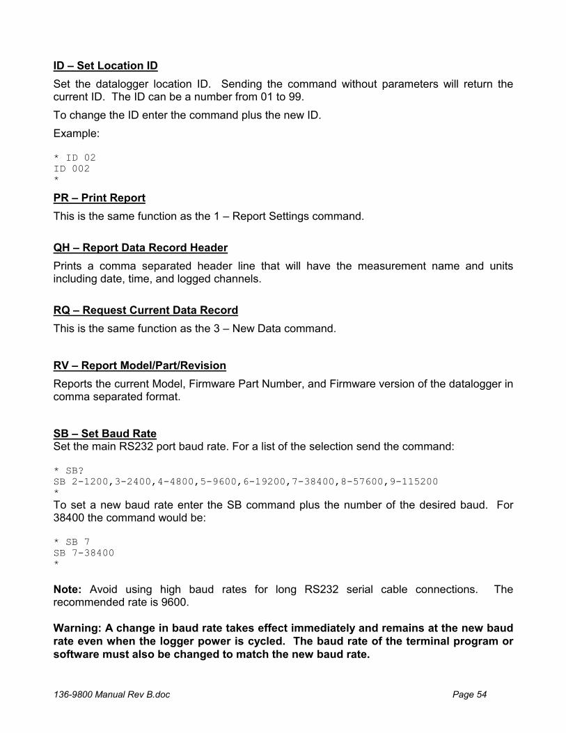
ID – Set Location ID
Set the datalogger location ID. Sending the command without parameters will return the current ID. The ID can be a number from 01 to 99.
To change the ID enter the command plus the new ID.
Example: * ID 02 ID 002 *
PR – Print Report
This is the same function as the 1 – Report Settings command.
QH – Report Data Record Header
Prints a comma separated header line that will have the measurement name and units including date, time, and logged channels.
RQ – Request Current Data Record
This is the same function as the 3 – New Data command.
RV – Report Model/Part/Revision
Reports the current Model, Firmware Part Number, and Firmware version of the datalogger in comma separated format.
SB – Set Baud Rate Set the main RS232 port baud rate. For a list of the selection send the command: * SB? SB 2-1200,3-2400,4-4800,5-9600,6-19200,7-38400,8-57600,9-115200 *
To set a new baud rate enter the SB command plus the number of the desired baud. For 38400 the command would be: * SB 7 SB 7-38400 *
Note: Avoid using high baud rates for long RS232 serial cable connections. The recommended rate is 9600. Warning: A change in baud rate takes effect immediately and remains at the new baud rate even when the logger power is cycled. The baud rate of the terminal program or software must also be changed to match the new baud rate.

136-9800 Manual Rev B.doc Page 55
SS – Get Serial Number
Report the Serial Number of the logger.
ST – Set Sample Time
Set the averaging sample time of the logger. The time selections can be viewed by using the command:
* ST?
ST 0-1 MIN,1-5 MIN,2-10 MIN,3-15 MIN,4-30 MIN,5-60 MIN
*
The following example shows how to set the sample time to 60 minutes: * ST 5 ST 5-60 Min *
136-9800 Manual Rev B.doc Page 56
11.2. Appendix B – Extended Commands
<Esc>1 - Display Current Day Averages
Display today’s averages only for the High Resolution file.
<Esc>2 - Display All Averages
Display all the averages stored in the 136 unit memory for the High Resolution file.
<Esc>3 - Display New Averages
Display Averages that were not previously retrieved for the High Resolution file.
<Esc>RF -Reset File Memory
This is a destructive command. Activation will erase all data in the high resolution file. The Legacy file is left intact. Password is required.
<Esc>XP - Change Download Pointer
This is the pointer for keeping track of the last entry of the high resolution data memory. If the memory is full, then the oldest data is written over first. This is the equivalent of the ‘p’ command for the High Resolution file.
<Esc>XB - XMODEM Download of Data
This command is used by Air Plus 5 software for binary data downloading. This is a proprietary command that requires software handshaking and is not recommended for terminal software operation.
<Esc>XR - XMODEM Download of Real Time Values
This command is used by Air Plus 5 software. This is a proprietary command that requires software handshaking and is not recommended for terminal software operation.

136-9800 Manual Rev B.doc Page 57
11.3. Appendix C – Updating Firmware
Consult the factory for updating the 136 Firmware.
136-9800 Manual Rev B.doc Page 58
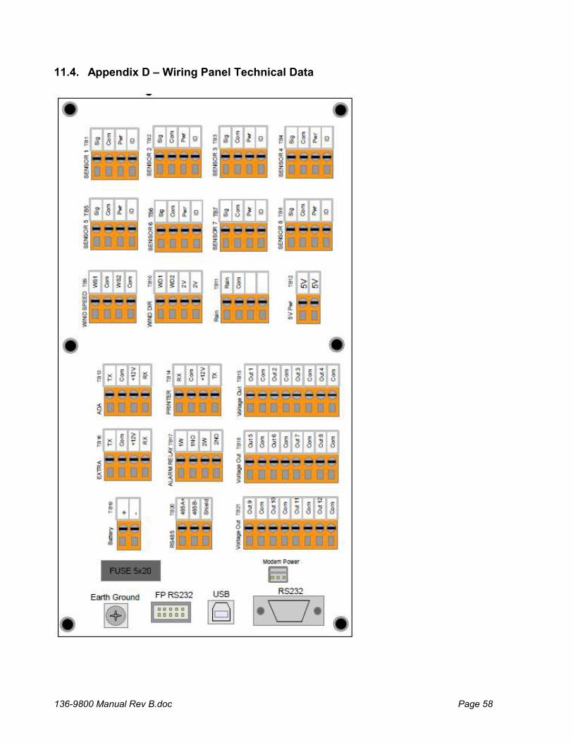
11.4. Appendix D – Wiring Panel Technical Data
136-9800 Manual Rev B.doc Page 59
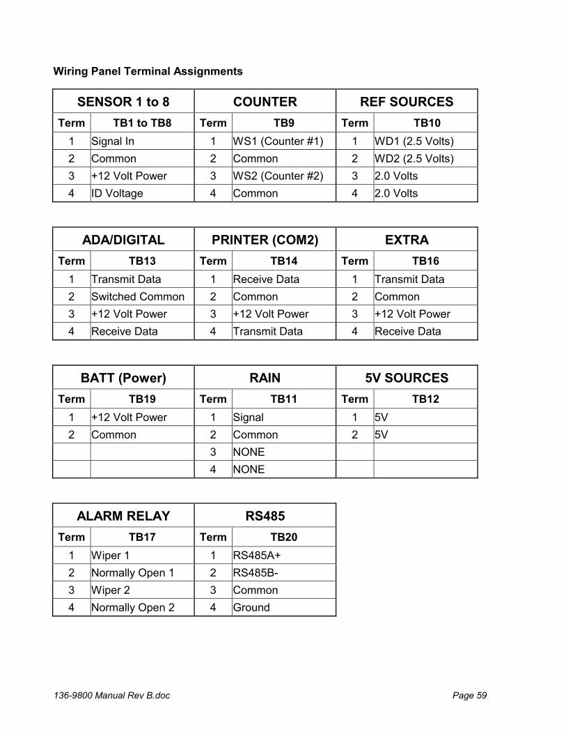
Wiring Panel Terminal Assignments
SENSOR 1 to 8 COUNTER REF SOURCES
Term TB1 to TB8 Term TB9 Term TB10
1 Signal In 1 WS1 (Counter #1) 1 WD1 (2.5 Volts)
2 Common 2 Common 2 WD2 (2.5 Volts)
3 +12 Volt Power 3 WS2 (Counter #2) 3 2.0 Volts
4 ID Voltage 4 Common 4 2.0 Volts
ADA/DIGITAL PRINTER (COM2) EXTRA
Term TB13 Term TB14 Term TB16
1 Transmit Data 1 Receive Data 1 Transmit Data
2 Switched Common 2 Common 2 Common
3 +12 Volt Power 3 +12 Volt Power 3 +12 Volt Power
4 Receive Data 4 Transmit Data 4 Receive Data
BATT (Power) RAIN 5V SOURCES
Term TB19 Term TB11 Term TB12
1 +12 Volt Power 1 Signal 1 5V
2 Common 2 Common 2 5V
3 NONE
4 NONE
ALARM RELAY RS485
Term TB17 Term TB20
1 Wiper 1 1 RS485A+
2 Normally Open 1 2 RS485B-
3 Wiper 2 3 Common
4 Normally Open 2 4 Ground
136-9800 Manual Rev B.doc Page 60
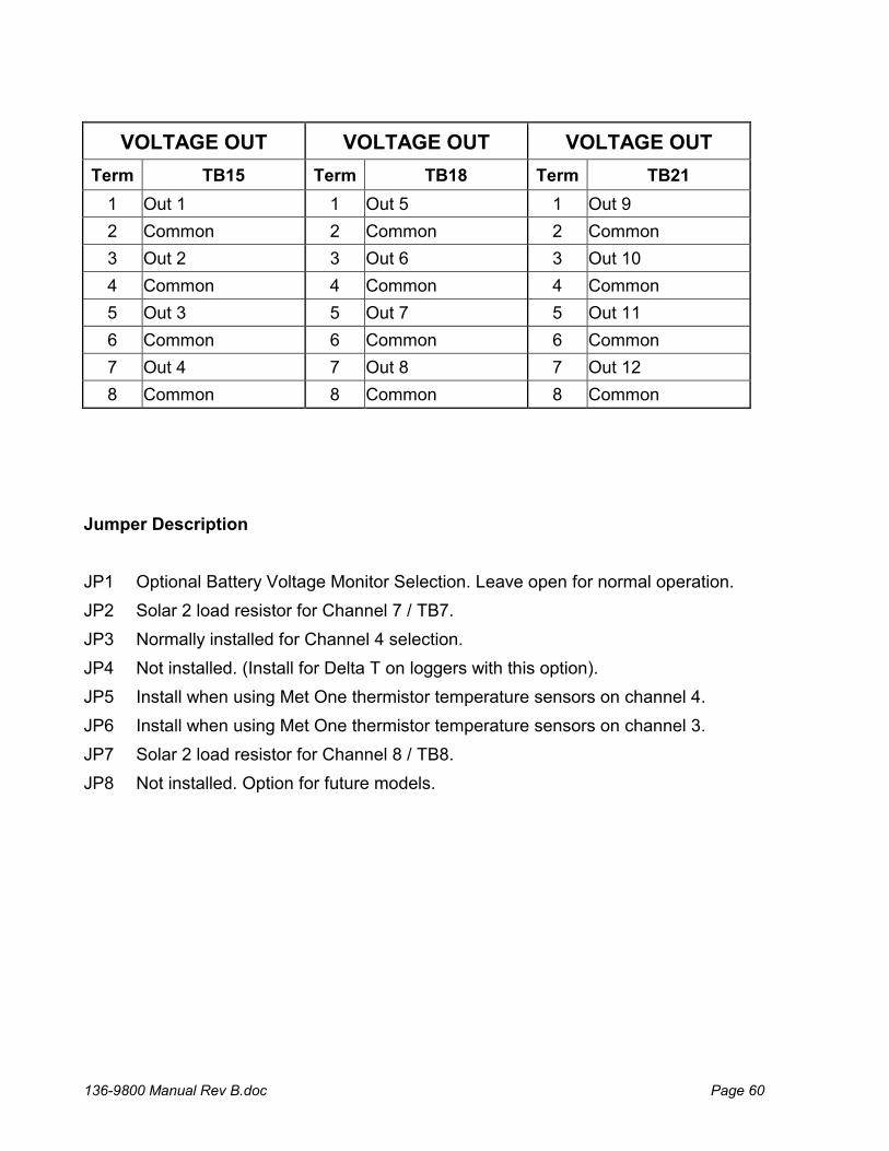
VOLTAGE OUT VOLTAGE OUT VOLTAGE OUT
Term TB15 Term TB18 Term TB21
1 Out 1 1 Out 5 1 Out 9
2 Common 2 Common 2 Common
3 Out 2 3 Out 6 3 Out 10
4 Common 4 Common 4 Common
5 Out 3 5 Out 7 5 Out 11
6 Common 6 Common 6 Common
7 Out 4 7 Out 8 7 Out 12
8 Common 8 Common 8 Common
Jumper Description
JP1 Optional Battery Voltage Monitor Selection. Leave open for normal operation.
JP2 Solar 2 load resistor for Channel 7 / TB7.
JP3 Normally installed for Channel 4 selection.
JP4 Not installed. (Install for Delta T on loggers with this option).
JP5 Install when using Met One thermistor temperature sensors on channel 4.
JP6 Install when using Met One thermistor temperature sensors on channel 3.
JP7 Solar 2 load resistor for Channel 8 / TB8.
JP8 Not installed. Option for future models.

136-9800 Manual Rev B.doc Page 61
11.5. Appendix E – Serial Output Record Formats
There are two record formats available from the 136 serial ports:
MetRecord Format – Standard Met One Data Format UIM Format – Compatible with Climatronics UIM systems.
11.5.1. MetRecord Format
A header will contain column text containing Date/Time, Channel Names, and Status in comma separated format. This is useful when importing records into a spreadsheet. Each record including the header contains a checksum. See the section below for an explanation of the CHECKSUM field. In the MetRecord format there is one space following the date stamp; data fields following are comma separated with no spaces. Example: 2014-06-05 13:21:00,00046.3,00079.7,+0450.0,00105.6,0025.30, +0123.2,00046.4,000.215,0000.00,00079.7,0015.10,00000,*05538 The field order is:
1 Date/Time 2 Log Chan1 3 Log Chan2 4 Log Chan3 5 Log Chan4 6 Log Chan5 7 Log Chan6 8 Log Chan7 9 Log Chan8 10 Rain 11 Sigma 12 Battery Voltage 13 Status
The status field is a bitwise numeric indication of the logger status including alarms and system calibration flag. See the section below for an explanation of the STATUS field. When serial records are requested by a serial command, a header line containing the field information is output first followed by records.
136-9800 Manual Rev B.doc Page 62
11.5.2. UIM Record Format
The data record format for an UIM record is space separated using fixed width fields. All fields have a polarity sign and a two digit field number (with leading zeros). Each field is 10 bytes wide. Example: 01+B1234 02+0046.3 03+0079.6 04+0450.0 05+0105.6 06+025.30 07+0123.2 08+0046.4 09+00.215 10+000.00 11+0079.6 12+015.10
The field order is: 01 Logger Serial Number and leading letter 02 Log Chan1 03 Log Chan2 04 Log Chan3 05 Log Chan4 06 Log Chan5 07 Log Chan6 08 Log Chan7 09 Log Chan8 10 Rain 11 Sigma 12 Battery Voltage
136-9800 Manual Rev B.doc Page 63
11.5.3. Status Field Format
The status field is a bitwise combination of values indicating the various types of alarms and calibrations status of the logger. The status field is a 5-digit value with a leading zero. Normally, the value in the status is a value of zero. When any bit is set, the status value is non-zero. These are the values assigned to the bits: Bit Value 1 = Alarm 1 1 2 = Alarm 2 2 3 = Digital Sensor Not Found 4 4 = Reserved 8 5 = Reserved 16 6 = Reserved 32 7 = Reserved 64 8 = Calibration Flag 128 If more than one status bit condition exists then the value for each condition is added to the total status value. For example, if Alarm 1 and Alarm 2 were set during a system calibration then the status would be computed as: 1 + 2 + 128 = 131 Reserved bits may be defined in future versions of the logger.
11.5.4. Record Checksums
Checksum is calculated as the 16 bit unsigned integer sum of all of the characters up to but not Including the Checksum Delimiter Character * (0x2A). It is printed out as an ASCII decimal number.
The result is always 5 characters in length with a leading zero.
136-9800 Manual Rev B.doc Page 64
11.6. Appendix F – Wind Direction Sensor Orientation
Introduction
Determining True North or Magnetic Declination is very important to the proper setup and orientation of the wind direction portion of the sonic wind sensor. The declination value is used to determine the difference between True North and magnetic North. This value varies around the world depending upon your location. The following procedure can be used to align the wind sensor to True North.
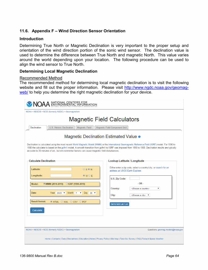
Determining Local Magnetic Declination
Recommended Method The recommended method for determining local magnetic declination is to visit the following website and fill out the proper information. Please visit http://www.ngdc.noaa.gov/geomag-web/ to help you determine the right magnetic declination for your device.
136-9800 Manual Rev B.doc Page 65
Secondary Method Several resources for determining the magnetic declination of any site in the world can be found on the internet or can be accessed by modem using any common terminal program.
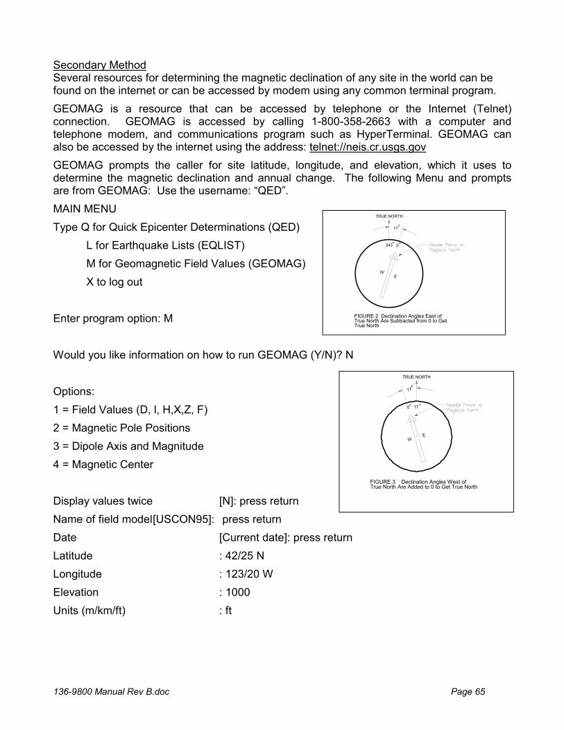
GEOMAG is a resource that can be accessed by telephone or the Internet (Telnet) connection. GEOMAG is accessed by calling 1-800-358-2663 with a computer and telephone modem, and communications program such as HyperTerminal. GEOMAG can also be accessed by the internet using the address: telnet://neis.cr.usgs.gov
GEOMAG prompts the caller for site latitude, longitude, and elevation, which it uses to determine the magnetic declination and annual change. The following Menu and prompts are from GEOMAG: Use the username: “QED”.
MAIN MENU
Type Q for Quick Epicenter Determinations (QED)
L for Earthquake Lists (EQLIST)
M for Geomagnetic Field Values (GEOMAG)
X to log out
Enter program option: M
Would you like information on how to run GEOMAG (Y/N)? N
Options:
1 = Field Values (D, l, H,X,Z, F)
2 = Magnetic Pole Positions
3 = Dipole Axis and Magnitude
4 = Magnetic Center
Display values twice [N]: press return
Name of field model [USCON95]: press return
Date [Current date]: press return
Latitude : 42/25 N
Longitude : 123/20 W
Elevation : 1000
Units (m/km/ft) : ft
TRUE NORTH
0343
WE
17
FIGURE 2 Declination Angles East ofTrue North Are Subtracted from 0 to GetTrue North
oo
o
TRUE NORTH
FIGURE 3 Declination Angles West ofTrue North Are Added to 0 to Get True North
17o
0 17oo
WE
136-9800 Manual Rev B.doc Page 66
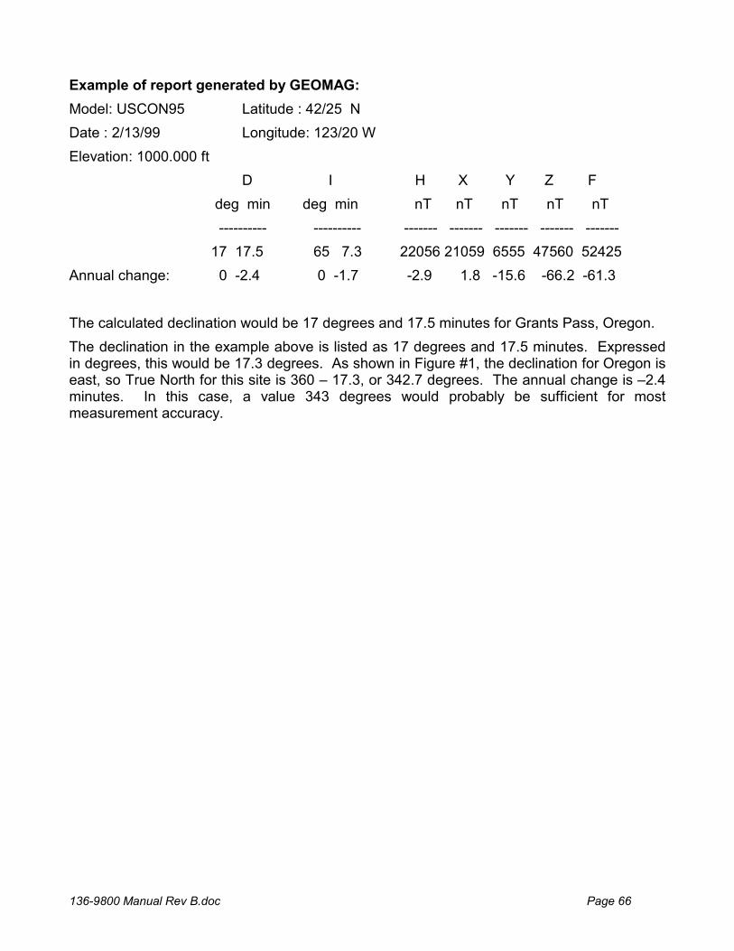
Example of report generated by GEOMAG:
Model: USCON95 Latitude : 42/25 N
Date : 2/13/99 Longitude: 123/20 W
Elevation: 1000.000 ft
D I H X Y Z F
deg min deg min nT nT nT nT nT
---------- ---------- ------- ------- ------- ------- -------
17 17.5 65 7.3 22056 21059 6555 47560 52425
Annual change: 0 -2.4 0 -1.7 -2.9 1.8 -15.6 -66.2 -61.3
The calculated declination would be 17 degrees and 17.5 minutes for Grants Pass, Oregon.
The declination in the example above is listed as 17 degrees and 17.5 minutes. Expressed in degrees, this would be 17.3 degrees. As shown in Figure #1, the declination for Oregon is east, so True North for this site is 360 – 17.3, or 342.7 degrees. The annual change is –2.4 minutes. In this case, a value 343 degrees would probably be sufficient for most measurement accuracy.

136-9800 Manual Rev B.doc Page 67
An alternate internet site at URL address
http://swdcwww.kugi.kyoto-u.ac.jp/igrf/point/index.html
provides a map of the world and you can move the mouse pointer to any position and select with the left mouse button. It will then calculate the magnetic declination for the selected point on the map (shown below)
An alternative method is to find a USGS map and examine the text at the bottom center of the map. At this point either a written indication is given, or a symbol similar to the one seen below will be found. This would indicate a declination of 15 degrees West-showing MN (magnetic North) to True North (Star). Other sources such as the local airport can be helpful in determining the correct declination.
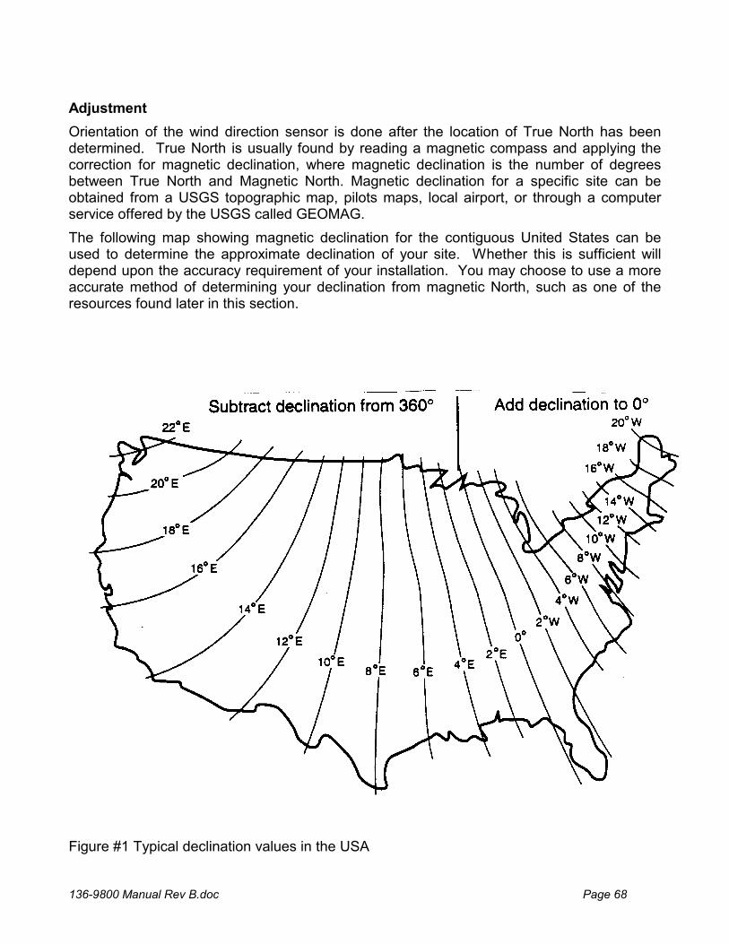
136-9800 Manual Rev B.doc Page 68
Adjustment
Orientation of the wind direction sensor is done after the location of True North has been determined. True North is usually found by reading a magnetic compass and applying the correction for magnetic declination, where magnetic declination is the number of degrees between True North and Magnetic North. Magnetic declination for a specific site can be obtained from a USGS topographic map, pilots maps, local airport, or through a computer service offered by the USGS called GEOMAG.
The following map showing magnetic declination for the contiguous United States can be used to determine the approximate declination of your site. Whether this is sufficient will depend upon the accuracy requirement of your installation. You may choose to use a more accurate method of determining your declination from magnetic North, such as one of the resources found later in this section.
Figure #1 Typical declination values in the USA

136-9800 Manual Rev B.doc Page 69
Declination angles east of True North are considered negative, and are subtracted from 0 or (360) degrees to get True North as shown in figure #2. Declination angles west of True North are considered positive, and are added to 0 degrees to get True North as shown in figure #3. For example, the declination for Grants Pass, Oregon is 17° East. True North is 360° -17°, or 343° as read on a compass.
Alignment to North
Orientation is most easily done with two people, one to aim and adjust the sensor, while the other observes the wind direction display. (Once True North is located, the South reference can be determined)
1. Establish a reference point on the horizon for True North.
Sighting down the instrument centerline, aim the two arms of the North/South pair at True North with the locking set screw pointed south.
2. Align the sensor adapter or adapter mount.
Loosen the setscrews that secure the base of the sensor to the cross arm. While viewing the position/rotation of the North/South sensor arms, slowly rotate the sensor base until the two arms point to True North that was determined by earlier measurement using compass.
Other methods employ observations using the North Star or the sun, and are discussed in the Quality Assurance Handbook for Air Pollution Measurement Systems, Volume IV Meteorological Measurements.
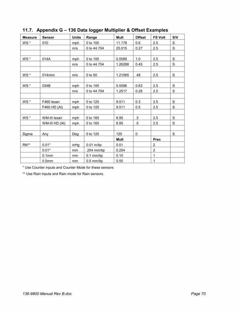
136-9800 Manual Rev B.doc Page 70
11.7. Appendix G – 136 Data logger Multiplier & Offset Examples
Measure Sensor Units Range Mult Offset FS Volt S/V
WS * 010 mph 0 to 100 11.178 0.6 2.5 S
m/s 0 to 44.704 25.015 0.27 2.5 S
WS * 014A mph 0 to 100 0.5589 1.0 2.5 S
m/s 0 to 44.704 1.26288 0.45 2.5 S
WS * 014mini m/s 0 to 50 1.21065 .49 2.5 S
WS * 034B mph 0 to 100 0.5596 0.63 2.5 S
m/s 0 to 44.704 1.2517 0.28 2.5 S
WS * F460 lexan mph 0 to 125 9.511 0.3 2.5 S
F460 HD (Al) mph 0 to 125 9.511 0.5 2.5 S
WS * WM-III lexan mph 0 to 165 6.95 .3 2.5 S
WM-III HD (Al) mph 0 to 165 6.95 .5 2.5 S
Sigma Any Deg 0 to 120 120 0 S
Mult Prec
RN** 0.01" inHg 0.01 in/tip 0.01 2
0.01" mm .254 mm/tip 0.254 2
0.1mm mm 0.1 mm/tip 0.10 1
0.5mm mm 0.5 mm/tip 0.50 1
* Use Counter inputs and Counter Mode for these sensors
** Use Rain inputs and Rain mode for Rain sensors.
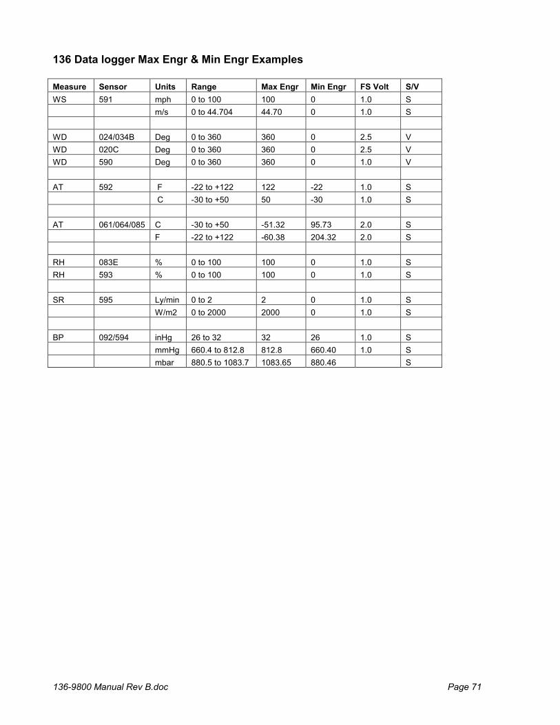
136-9800 Manual Rev B.doc Page 71
136 Data logger Max Engr & Min Engr Examples Measure Sensor Units Range Max Engr Min Engr FS Volt S/V
WS 591 mph 0 to 100 100 0 1.0 S
m/s 0 to 44.704 44.70 0 1.0 S
WD 024/034B Deg 0 to 360 360 0 2.5 V
WD 020C Deg 0 to 360 360 0 2.5 V
WD 590 Deg 0 to 360 360 0 1.0 V
AT 592 F -22 to +122 122 -22 1.0 S
C -30 to +50 50 -30 1.0 S
AT 061/064/085 C -30 to +50 -51.32 95.73 2.0 S
F -22 to +122 -60.38 204.32 2.0 S
RH 083E % 0 to 100 100 0 1.0 S
RH 593 % 0 to 100 100 0 1.0 S
SR 595 Ly/min 0 to 2 2 0 1.0 S
W/m2 0 to 2000 2000 0 1.0 S
BP 092/594 inHg 26 to 32 32 26 1.0 S
mmHg 660.4 to 812.8 812.8 660.40 1.0 S
mbar 880.5 to 1083.7 1083.65 880.46 S
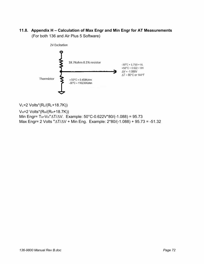
136-9800 Manual Rev B.doc Page 72
11.8. Appendix H – Calculation of Max Engr and Min Engr for AT Measurements
(For both 136 and Air Plus 5 Software)
VL=2 Volts*(RL/(RL+18.7K))
VH=2 Volts*(RH/(RH+18.7K)) Min Engr= TH-VH*∆T/∆V. Example: 50°C-0.622V*80/(-1.088) = 95.73 Max Engr= 2 Volts *∆T/∆V + Min Eng. Example: 2*80/(-1.088) + 95.73 = -51.32
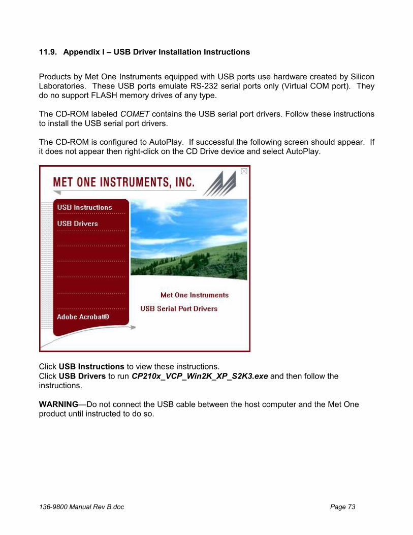
136-9800 Manual Rev B.doc Page 73
11.9. Appendix I – USB Driver Installation Instructions
Products by Met One Instruments equipped with USB ports use hardware created by Silicon Laboratories. These USB ports emulate RS-232 serial ports only (Virtual COM port). They do no support FLASH memory drives of any type. The CD-ROM labeled COMET contains the USB serial port drivers. Follow these instructions to install the USB serial port drivers. The CD-ROM is configured to AutoPlay. If successful the following screen should appear. If it does not appear then right-click on the CD Drive device and select AutoPlay.
Click USB Instructions to view these instructions. Click USB Drivers to run CP210x_VCP_Win2K_XP_S2K3.exe and then follow the instructions. WARNING—Do not connect the USB cable between the host computer and the Met One product until instructed to do so.
Related Documents