Embedded Project- ECE 5101 Page 1 Embedded Systems-Fall 2005 ECGR 5101 Final project On By: Boda Vamsee Krishna Babu (999066887) Email id: [email protected] Bajjuri Praneeth Kumar (999067008) Email id: [email protected]

13356189746659-Gsm-Project
Oct 22, 2015
gsm
Welcome message from author
This document is posted to help you gain knowledge. Please leave a comment to let me know what you think about it! Share it to your friends and learn new things together.
Transcript

�������������������
Embedded Project- ECE 5101 Page 1
Embedded Systems-Fall 2005
ECGR 5101 Final project
On
�������������������
By: Boda Vamsee Krishna Babu (999066887) Email id: [email protected] Bajjuri Praneeth Kumar (999067008) Email id: [email protected]

�������������������
Embedded Project- ECE 5101 Page 2
INDEX 1. Abstract-------------------------------------------------------------------------------------------2 2. Project Description------------------------------------------------------------------------------3 3. Device Description 3.1 Renesas SKP16C62P Starter Kit Plus -------------------------------------------------4 3.2 GSM modem------------------------------------------------------------------------------ 5 3.3 Power connection ------------------------------------------------------------------------ 6 3.4 Antenna Connection --------------------------------------------------------------------- 6 3.5 SIM card Reader-------------------------------------------------------------------------- 7
4. MAX232 Chip---------------------------------------------------------------------------------- 8 5. RS232 Standard---------------------------------------------------------------------------------8 6. GM28 Communication System---------------------------------------------------------------9 7. AT commands-----------------------------------------------------------------------------------10 8. Installation and Functionality of modem-----------------------------------------------------11 9. Short Message Service-------------------------------------------------------------------------13 10. PDU SMS format------------------------------------------------------------------------------13 11. Code --------------------------------------------------------------------------------------------14 12. Snapshots from Project 12.1 Snapshots from hyper-terminal-----------------------------------------------------25 12.2 Photos of complete project setup---------------------------------------------------26 13. Observations---------------------------------------------------------------------------- -------27 14. Precautions--------------------------------------------------------------------------- ----------27 15. Conclusions-------------------------------------------------------------------------------------27 16. References--------------------------------------------------------------------------------------28

�������������������
Embedded Project- ECE 5101 Page 3
SMS REMOTE CONTROLLER
1. Abstract
The goal of this project is to design an embedded device which can control up to 8 devices by sending a specific SMS message from a cell-phone. This controller is extremely handy at places where we have to control the ON and OFF switching of the devices but no wired connection to that place is available.
To implement this, a GSM modem is connected to a programmed microcontroller which would receive the SMS from a reference cell phone. The control signal part of the received SMS is extracted and is changed to microcontroller-preferred format. In regular intervals, the modem would also send the local temperature We have selected GSM because the ubiquity of its standard makes international roaming very common between mobile phone operators, enabling subscribers to use their phones in many parts of the world. A PC which is connected to the micro-controller using a serial communication through RS232 can be used for monitoring and transmission of the control signals to the modem. The monitoring is also done by interfacing a LCD to the microcontroller. AT commands were used for controlling the functionality of modem. Main hardware requirements:
Ø Renesas SKP16C62P Starter Kit Plus This contains the micro-controller. (used for controlling the different external devices connected as per the SMS received )
Ø GSM modem (GM28 from Sony-Ericsson) This GSM/GPRS terminal equipment is a powerful, compact and self contained unit with standard connector interfaces and has an integral SIM card reader. It is used for receiving the SMS from the mobile device and then to transmit to the Renesas SKP.
Ø A MAX232 chip
This converter chip is needed to convert a TTL logic from a Microcontroller (TxD and RxD pins ) to standard serial interfacing for PC (RS232)
Ø A DB9 connector
This takes the signals coming form the MAX232 chip to the PC. The typical applications of this serial modem is for developing a wide range of equipment like à Security and alarms devices à Monitoring and control devices à Vending machines à Utilities devices à Fleet Management devices

�������������������
Embedded Project- ECE 5101 Page 4
2. Project Description
Figure 1: Block diagram of the project setup
Initially the SMS is received from the person authorized to use this setup (destination)
by the GSM modem (GM28) & is transferred to the Renesas SKP16C62P SKP with the help of a MAX 232 chip. As per the AT commands given by the microcontroller to the modem, the control signal from the SMS is extracted and is used to control the devices connected to it. We have to convert the 'septets' of the phone to 'octets' because the micro-controller need bytes with 8 bits length ( The 'septet' is 1 byte with 7 bits length and 'octet' is 1 byte with 8 bits length). All this process is necessary to decode the message from SMS.
A program (for extracting the control signal part from received SMS) is loaded into Renesas SKP16C62P SKP, and then the circuit is connected to the modem. The micro-controller now tries to read the SMS from the 1st memory location of the modem and it keeps trying again until the modem receives any (programmed for every one second). Before implementing the control signal part of the SMS, the modem extracts the number from the SMS and verifies if this number has the access to control the device or not.
For controlling the devices, the message will be sent in hexa decimal format. The hex data is converted to the equivalent binary and the particular output is enabled. For example if the message is “AB” the equivalent binary is “10101011” this implies that the output 1, 3, 5, 7, 8 are enabled and the remaining ports are disabled. We have connected LEDs to the ports of microcontroller to show the output and their status indicates whether the ports are set to ‘ON’ or ‘OFF’. The microcontroller is also programmed to read the temperature from the thermistor every 15 minutes and to send a SMS to the destination number.
DB9 Connector
MAX 232
GM28 (GSM Modem with SIM card working in 850 MHz /1900 Hz)
DB9 Connector
Renesas SKP16C62P
Starter Kit Plus
Device 2
Device 1
Device 8
Computer (For displaying the received SMS)
Antenna

�������������������
Embedded Project- ECE 5101 Page 5
3. Device Description 3.1. Renesas SKP16C62P Starter Kit Plus
The SKP16C62P StarterKit Plus (SKP) is a low-cost environment for evaluating
M16C/62P group of microcontrollers (MCU) and Renesas Technology America, Inc. software development tools. The SKP board provides an evaluation and development environment for the M16C/62P group of MCU. It has pushbutton switches, LED’s and LCD for user interface. Standard connector ports are available to expand the range of applications through the use of expansion boards, etc. The kit comes with an integrated software development environment, HEW (IDE, C-compiler, assembler, and linker), KD30 Debugger, and FoUSB (Flash-over-USB™) Programmer. A real-time, source-level debug environment is implemented using the KD30 debugging software with the RTA-FoUSB-MON Flash Programmer/In-Circuit Debugger (ICD). The Flash-over-USBTM (FoUSB) Programmer software, with the ICD, allows in-system programming of the M16C/62P flash MCU. The ICD and firmware provide a convenient USB (Universal Serial Bus) interface between the SKP16C62P board and the host PC. This interface reduces resource requirements on the M16C/62P MCU, allows faster code downloads and, can also be used with many other Renesas Flash MCU’s, SKP’s, and user’s target board.
Figure 2: SKP16C62P System Connectivity
(From the hardware manual of SKP16c62P )
�������������������
Embedded Project- ECE 5101 Page 6
3.2 GSM modem: (GM28 from Sony-Ericsson)
Figures 3.a, 3.b and 3.c show the different views of the GSM modem GM28 (From the Hardware Manual of GM28 Modem)
The Global System for Mobile Communications (GSM) is the most popular standard for mobile phones in the world. It is the European standard for digital cellular service that includes enhanced features. It is based on TDMA technology and is used on 850/1900 MHz.
We are using the GM28, a GSM modem from Sony-Ericsson. This is a powerful GSM/GPRS Terminal with compact and self-contained unit. This has standard connector interfaces and has an integral SIM card reader. The modem has a RJ9 connector through which a speaker and microphone can be connected allowing audio calls being established, but this feature is not utilized in this project as only data transfer is needed. Following are few technical details of the modem.
Interfaces:
• Data: RS232 9–way (V.28) • Power and Extended I/Os: 5 – 32VDC (RJ11) • Audio 4-wire Handset Interface (RJ9) • Antenna: 50� (FME male) • SIM card reader: 3V/5V interface with SIM detection
Features: • ME + SIM phone book management – read/write/find, call screening, groups • SIM Application Toolkit Class 2 • Real Time Clock • Software upgradeable • Audio control • Fixed dialing number • UCS2 16 bit data supported.
Figure 3.c Figure 3.b
Figure 3.a

�������������������
Embedded Project- ECE 5101 Page 7
SMS features
• Supports both Text and PDU modes • MT/MO & CBM • Cell Broadcast • Concatenation – up to 6 SMS
The TT4030 (SE-GM28) uses the following industry standard connectors to interface with the external application and the GSM network;
• RJ11 (plug-in power supply connector). • RJ9 (handset audio connector) • Integral SIM card reader. • FME male (antenna connector). • Sub-D socket, 9 pin (RS232 serial port).
3.3. Power Connections All electrical connections to the TT4030 (SE-GM28) are designed to meet the standard air (4 kV) and contact (8 kV) discharge ESD tests, of EN 301 489-1.
Figure 4 RJ11 connector as power supply to the modem
(From the Hardware Manual of GM28 Modem)
3.4. Antenna Connections The used antenna (Figure 4.a) operates at 850/1900 MHz which is suitable for transmitting and receiving of RF signals for the GSM modem (GM28) used. Some of the key features of this antenna are:
• Bandwidth is 280 MHz • VSWR is <1.6 • Gain 3.5 db • Antenna length is 120mm • Cable type RG174

�������������������
Embedded Project- ECE 5101 Page 8
Figure 5.a GSM-JC01-NA (GSM antenna for GM28) Figure 5.b Antenna connector on the modem
(From the Hardware Manual of GM28 Modem) The antenna connector (Figure 5.b) allows transmission of radio frequency (RF) signals between the modem and an external customer-supplied antenna. The modem is fitted with a 50db FME male coaxial jack. 3.5. SIM card Reader The TT4030 (SE-GM28) is fitted with a SIM card reader designed for 3 V and 5 V SIM cards. It is the flip-up type, which is lockable in the horizontal position and is accessed through a removable panel. The SIM card reader includes a SIM presence switch. This ensures that when a SIM card is inserted or removed while the TT4030 (SE-GM28) is turned ON, it will reset.
Figure 6 Sketches of SIM card reader on the GM28 modem.
(From the Hardware Manual of GM28 Modem)
1 2
3 4

�������������������
Embedded Project- ECE 5101 Page 9
4. MAX 232 Chip
Figure 7.a Pin configurations of MAX232 chip Figure 7.b Logic conversion that takes place in MAX232 chip.
(Took from the Hardware Manual of MAX232 IC) The MAX232 device is a dual driver/receiver that includes a capacitive voltage generator to supply EIA-232 voltage levels from a single 5-V supply. Each receiver converts EIA-232 inputs to 5-V TTL/CMOS levels. Each driver converts TTL/CMOS input levels into EIA-232 levels. A max232 chip is used to do the level shifting and this chip is required to send data serially to a PC which requires voltage levels as per RS232 standard. 5. RS232 Standard
Figure 8 Pin configuration of DB9 connector for Null modem. RS232 is an electrical signaling specification published by the Electronic Industries Association (EIA). Although not identified in the specification, the 9-pin (DB9) connector, with specific pin assignments, is commonly accepted as "the RS232 connector or the serial connector." This standard interface provides connection for only modest transmission rates & is often used with modems. The general voltage assignment is:
Signal = 0 (LOW) > +3.0V
Signal = 1 (HIGH) < -3.0V

�������������������
Embedded Project- ECE 5101 Page 10
Pin No.
Name Notes/Description
1 DCD Data Carrier Detect
2 RD Receive Data (a.k.a RxD, Rx)
3 TD Transmit Data (a.k.a TxD, Tx)
4 DTR Data Terminal Ready
5 SGND Ground
6 DSR Data Set Ready
7 RTS Request To Send
8 CTS Clear To Send
9 RI Ring Indicator
Table 1 Pin description of a DB9 connector
6. GM28 in a Communication System Figure 10, Illustrates the main blocks of a wireless communication system using the TT4030 (SE-GM28). It also shows the communication principles of the system. The definitions in the figure are in accordance with the recommendations of GSM 07.07. à The MS (mobile station) represents the TT4030 (SE-GM28) modem plus SIM card. The modem excluding SIM card, is known as the ME (mobile equipment). à The TE (terminal equipment) is a micro-controller and is a part of the application.
Figure 10.a Main blocks in communication between the GM28 (modem) and the microcontroller (TE) (From the Hardware Manual of GM28 Modem)
The end-to-end communication path to be established between the external telemetry/ telematics application and a remote terminal or host, via the GSM network is done through the serial communication. Serial data with flow control according to the RS232 signaling protocol operates between the modem and the external application. The modem performs a set of telecom services (TS) according to GSM standard phase 2+, ETSI and ITU-T. Control of the TT4030 (SE-GM28) is by the external application, via the RS232 serial interface, using a set of AT commands. The TT4030 (SEGM28) supports the full set of AT commands according to GSM 07.05 and GSM 07.07. It also supports an extended set of Ericsson proprietary AT commands to add extra functionality.

�������������������
Embedded Project- ECE 5101 Page 11
AT commands are used to operate the modem and have a broad range of Functions including: à Configuring general parameters of the modem (SE-GM28) à Setting up and controlling communications to and from the GSM Network à Configuring the modem to communicate across the RS232 serial interface à Obtaining GSM network status information. The modem also supports the Voice, Data, Fax services but since these are not required for the current application, they are not taken into consideration as of now. 7. AT commands The AT command set is the fundamental interface with the modem. An AT command is simply a string of characters preceded by the AT prefix that is sent to the modem. The commands typically instruct the modem to perform some action or set some characteristic within the modem. The modem has two states: command state and on-line state. In command state, the modem will accept and respond to AT commands. In the on-line state, the modem will transmit data, but ignore AT commands. Typically the modem is in the on-line state after dialing. AT commands has the following format:
Ø The command is prefixed with AT (Attention) Ø The command is terminated by a carriage return <CR> (except the A/ command and
escape sequence). Ø The commands can be entered in upper case or lower case. Ø The AT prefix can be in upper case or lower case, but both the A and the T must be the
same case. Ø Characters that precede the AT prefix are ignored. Ø Multiple commands can be strung together on a single line and spaces may be included
between commands but are not necessary. The command line interpretation begins upon receipt of the carriage return. These commands are used for request information about the current configuration or operational status of the mobile phone/modem and test availability and request the range of valid parameters, when applicable, for an AT command.
Figure 10.b Interface between the GM28 (modem) and microcontroller (TE) (From the Hardware Manual of GM28 Modem)

�������������������
Embedded Project- ECE 5101 Page 12
General Syntax of AT-Commands: Basic à AT<command> [=] [<parameter>] Extended à AT+<command>= [<parameter>] AT*<command>= [<parameter>] Read command à AT+<command>? AT*<command>? AT<command>? Test command à AT+<command>=? AT*<command>=? Response command à AT+<command> : <parameter > AT*<command> : <parameter>
Important AT command used to Test and Design:
1) ATD à To dial a voice call from the modem. 2) AT+IPRà To set the baud rate for the modem ( here for our application the baud rate is
set as 9600) 3) ATAà To answer an incoming call. 4) AT+CHUPà To hang up the initiated call. 5) AT+CFUNà To set the phone functionality. Set to 0 to deactivate the modem. 6) AT+CLIPà To identify caller number this command is set to 1 7) AT+CLIRà For calling line Identification Restriction. 8) AT+CNUMà To identify the subscriber number. 9) AT+CMGRà To read the message at particular location .The location number is given
as index. 10) AT+CMGDà To delete the received message 11) AT+CMGSà To send the message. 12) AT+CMGFà To change the message format to PDU or Text mode. 13) AT+CMGLà To see all the list of messages. 14) ATEà To enable and disable command echo.
8. Installation and Functionality of modem To install this modem in the communication system to PC, the following procedure is adopted:
• Select the phone and modem options from the control panel. • By browsing the disk for the modem drivers, the modem is selected and configured to a
particular port through which it is connected to the PC. • The terminal package like HyperTerminal is selected in the initial stage to check the
functionality of the AT commands to control the GSM modem and later this hyper terminal is just used to monitor the serially received output. Hence finally a three way communication is established, the modem directly communicates with the micro controller to control the switching of devices externally and the hyper terminal package in PC is used just for monitoring the results (hence only receive and ground of connected to the PC).
�������������������
Embedded Project- ECE 5101 Page 13
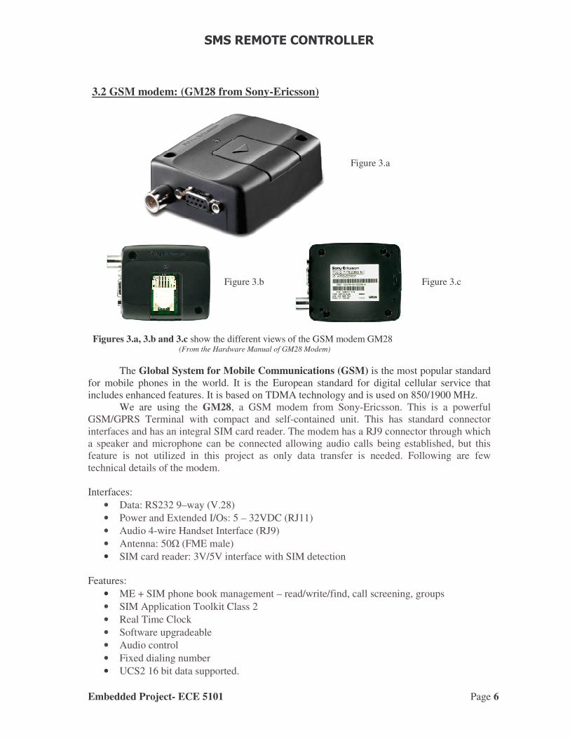
• The parameters for serial communication can be set in two ways; either by terminal equipment or by serial communication with the micro controller. It should be noticed that the DTR pin should be enabled high in the initial stage to turn-on the modem, for this flow control of hardware is to be taken and the communication initially is 115200 bauds/second with 8-n-1 configuration (i.e. 8-Data bits, Parity none and 1-Stop bit). Later the baud rate can be changed to 9600 bps through the AT command: AT+IPR = <desired baud >.
• The settings for the hyper-terminal should have the default input translation and ASCII setup, the emulation can be either VT100 (preferable) or Auto-detect.
To setup the serial port the following procedure has been followed:
• Select system from the control panel and thereby select the device manager in the hardware option.
• Now the exact serial COM port where the modem is configured is selected manually. • Select port settings and then bits per second to get the exact baud rate.
Now that the modem is configure it’s the task of setting up the volatile profile and enter the AT commands required to select the SIM memory and then extract the text message. Hence, serial communication is established between GM28 and the microcontroller using a DB9 connector with a level shifter (MAX232). A level shifter is connected between the microcontroller (SKP) and the modem/computer and null modem connection is connected for the DB9 connector. The above discussed points are depicted in the Figure 9.
Figure 9 Circuit for connecting the microcontroller to the modem/computer

�������������������
Embedded Project- ECE 5101 Page 14
9. Short Message Service (SMS) The GSM GM28 Modem supports the following SMS services.
Ø Sending, MO (mobile-originated) with both PDU (protocol data unit) and text mode supported.
Ø Receiving, MT (mobile-terminated) with both PDU and text mode supported. Ø CBM (cell broadcast message), a service in which a message is sent to all subscribers
located in one or more specific cells in the GSM network. This feature is network dependent.
Ø SMS STATUS REPORT according to GSM 03.40. Ø SMS COMMAND according to GSM 03.40.
It should be noted that the maximum length of an SMS message is 160 characters when using 7- bit encoding. For 8-bit data, the maximum length is 140 characters. The Modem supports up to 6 concatenated messages to extend this function. Before we start working on the application design we should ensure the network subscription status
Ø Before the application is implemented, we must ensure that the chosen network provides the necessary telecommunication services. Else, the service provider should be contacted to obtain the necessary information.
Ø Since SMS features are used in this application, we have to ensure that these are included in the (voice) subscription.
10. PDU SMS format:
There are two ways of sending and receiving SMS messages: by text mode and by PDU (protocol description unit) mode. We can switch from text mode to PDU mode and vice versa by selecting the AT+CMGF command. If AT+CMGF = 0 then PDU mode is selected and if the mode is 1 then text mode is selected. The text mode is just an encoding of the bit stream represented by the PDU mode. If we read the message on the phone, the phone will choose a proper encoding. An application capable of reading incoming SMS messages can thus use text mode or PDU mode. If text mode is used, the application is bound to the set of preset encoding options. In some cases, that's just not good enough. If PDU mode is used, any encoding can be implemented. The PDU string contains not only the message, but also a lot of meta-information about the sender, its SMS service center, the time stamp etc.But as of now for our application we require the phone number of the caller for authentication and the length of the message and the text message which contains the binary message. Let us take a example for the text message of “abcdef”. This message contains apart from the basic text message a lot of redundant data (meta information about the sender).
In PDU mode the SMS looks like: 07914140279542F7000B816187220731F700006010413283900A0661F1985C3603 In TEXT mode the SMS looks like: +CMGR: "REC READ","16782270137",,"06/01/14,23:56:17-20",129,0,0,0,"+14047259247",145,6 abcdef
�������������������
Embedded Project- ECE 5101 Page 15
The octets of the PDU message contain lots of information, in the above example the PDU can be divided and different octets signify the following information: 07à Length of SMSC information. 91à Type of address of SMSC. 4140279542F7à Encoded Service center number. 00à First octet of SMS delivery message. 0Bà Address length of the sender message. 81à Type of address of the sender number. 6187220731F7à Sender number with a trailing F.(number is 16872270137). 00à TP-Protocol Identification Address. 00à TP-Data coding Scheme. 601041328390à TP-SCTSà Time stamp. 0Aà TP-User data length. 0661F1985C3603à Encoded Message “abcdef”. All the octets are hexa-decimal 8-bit octets, except the Service center number, the sender number and the timestamp; they are decimal semi-octets. The message part in the end of the PDU string consists of hexa-decimal 8-bit octets, but these octets represent 7-bit data. Basically the transformation of the septets to the octets is based on the GSM 03.38 standard. This is helpful when we try to communicate with the PDU mode but if we use the CMGF command then text mode is activated to get the converted text message. So to get the message in the Text message we need to send the following commands AT+CMGF=1 to activate the text mode AT+CMGS=1 to check whether the modem supports the SMS message or not. AT+CMGR=I to read the message at the location I in the SIM card.
11. Code /*******************************************************************/
/* FILE :main.c
DATE : Jan 2nd 2006 */
/* DESCRIPTION :Main Program
To receive SMS from GM28 and to extract the control information part, then to control LEDs accordingly. Send the ambient temperature as SMS back to the user.
AUTHORS: B.VAMSEE KRISHNA & B.PRANEETH KUMAR
*/
/******************************************************************/
#include "skp_bsp.h"// include SKP board support package
#include "string.h"
void uartinit();

�������������������
Embedded Project- ECE 5101 Page 16
unsigned char result;
char sms_text[200],sms_msg[10],num_text[10];
unsigned int f,f1,t,time=0,k=0,count=0,p=0;
/* Prototype declarations */
void mcu_init(void); // MCU initialization
void main(void);
void timer_init(void);
void uartinit(void);
int map(char);
#pragma INTERRUPT rx_isr
void rx_isr(void);
/* DEFINE QUEUES*/
#define Q_SIZE (200)
typedef struct {
unsigned char Data[Q_SIZE];
unsigned int Head; // points to oldest data element
unsigned int Tail; // points to next free space
unsigned int Size; // quantity of elements in queue
} Q_T;
Q_T tx_q, rx_q;
int Q_Empty(Q_T * q) {
return q->Size == 0;
}
int Q_Full(Q_T * q) {
return q->Size == Q_SIZE;
}
int Q_Enqueue(Q_T * q, unsigned char d) {
// if queue is full, abort rather than overwrite and return
// an error code
if (!Q_Full(q)) {
q->Data[q->Tail++] = d;

�������������������
Embedded Project- ECE 5101 Page 17
q->Tail %= Q_SIZE;
q->Size++;
return 1; // success
} else
return 0; // failure
}
unsigned char Q_Dequeue(Q_T * q) {
// Must check to see if queue is empty before dequeueing
unsigned char t=0;
if (!Q_Empty(q)) {
t = q->Data[q->Head];
q->Data[q->Head++] = 0; // empty unused entries for debugging
q->Head %= Q_SIZE;
q->Size--;
}
return t;
}
void Q_Init(Q_T * q) {
unsigned int i;
for (i=0; i<Q_SIZE; i++)
q->Data[i] = 0; // to simplify our lives when debugging
q->Head = 0;
q->Tail = 0;
q->Size = 0;
}
void timer_init(void)
{
//Timer initialisation
ta0mr = 0x80;//timer mode
ta0 = 0x927C;//for 50 msec delay
ta0ic = 0x03;//timer priority
tabsr=0x01; // starting the timer

�������������������
Embedded Project- ECE 5101 Page 18
}
int map(char c)
{
int a=(int)c;
switch (a)
{
case 48:
return(0);
break;
case 49:
return(1);
break;
case 50:
return(2);
break;
case 51:
return(3);
break;
case 52:
return(4);
break;
case 53:
return(5);
break;
case 54:
return(6);
break;
case 55:
return(7);
break;
case 56:
return(8);
�������������������
Embedded Project- ECE 5101 Page 19
break;
case 57:
return(9);
break;
case 65: //returns 10 if 'A' is entered
return(10);
break;
case 97: //returns 10 if 'a' is entered
return(10);
break;
case 66: //returns 10 if 'B' is entered
return(11);
break;
case 98: //returns 10 if 'b' is entered
return(11);
break;
case 67: //returns 10 if 'C' is entered
return(12);
break;
case 99: //returns 10 if 'c' is entered
return(12);
break;
case 68: //returns 10 if 'D' is entered
return(13);
break;
case 100: //returns 10 if 'd' is entered
return(13);
break;
case 69: //returns 10 if 'E' is entered
return(14);
break;
case 101: //returns 10 if 'e' is entered

�������������������
Embedded Project- ECE 5101 Page 20
return(14);
break;
case 70: //returns 10 if 'F' is entered
return(15);
break;
case 102: //returns 10 if 'f' is entered
return(15);
break;
default:
break;
}
}
#pragma INTERRUPT timer_a0
void timer_a0(void) // the timer is set for every 50 milliseconds
{
int r,ad11_value;
char lcd_disp[11],temp_sms[22],lcd_temp[6];
float faren;
time+=50;
if(time==1000) //Checking for new SMS messages every 1second
{
time=0;
strcpy(lcd_disp,"AT+CMGR=1"); //AT command for retriving the recent SMS message
lcd_disp[9]=(char)13; // including <CR> at the end of the command
//lcd_disp[3]=(char)10; // for <LF> at the command, this takes to the new line
//DisplayString(LCD_LINE1,lcd_disp); // Displaying the command being sent
for(r= 0;r<10;r++)
{

�������������������
Embedded Project- ECE 5101 Page 21
//if (!Q_Enqueue(&tx_q,lcd_disp[r])) ;
while(!ti_u0c1);
u0tbl= lcd_disp[r];//Q_Dequeue(&tx_q);
}
lcd_disp[10] = '\0';
/* for(r= 0;r<3;r++)
{
while(!ti_u0c1);
u0tbl= Q_Dequeue(&tx_q);
}
*/ DisplayString(LCD_LINE1,lcd_disp);
//Q_Init(&tx_q);
YLW_LED ^=1;
}
/*
temp= temp+1; //temp variable is used for sending SMS every 10minutes
if (temp==12000)
{
DISABLE_IRQ;
strcpy(temp_sms,"AT+CMGS=\"7044998867\""); //command for sending SMS to number:7044998867
temp_sms[21]=(char)13;
for(r= 0;r<22;r++)
{
//if (!Q_Enqueue(&tx_q,lcd_disp[r])) ;
while(!ti_u0c1);
u0tbl= temp_sms[r];//Q_Dequeue(&tx_q);
}
ad11_value = ad1;
faren=tempconv(ad11_value);
temp=0;

�������������������
Embedded Project- ECE 5101 Page 22
}
IntToAsciiDec(lcd_temp,5,faren);
lcd_display1[4]=lcd_display1[3];
lcd_display1[3]='.';
lcd_display1[5]=(char)27;
for(r= 0;r<6;r++)
{
while(!ti_u0c1);
u0tbl= lcd_display[r];
}
}
ENABLE_IRQ;
}
/********************************************************************Name : main
Parameters : none
Returns : nothing
Description: Main template
*******************************************************************/
void main(void)
{
mcu_init(); /* Initialize MCU */
ENABLE_LEDS; /* LED initialization */
InitDisplay();
uartinit();
ENABLE_IRQ;
timer_init();
Q_Init(&tx_q);
Q_Init(&rx_q);
pd0=0xff;
while(1);
}

�������������������
Embedded Project- ECE 5101 Page 23
//*******************************************************//
#pragma INTERRUPT rx_isr
void rx_isr(void)
{
/*int j;
//char temp[2];
char lcd_disp1[7];
if(!Q_Enqueue(&rx_q,u0rbl));
k++;
if(k%6==0)
{
for(j=0;j<6;j++)
lcd_disp1[j]=Q_Dequeue(&rx_q);
DisplayString(LCD_LINE2,lcd_disp1);
RED_LED ^= 1;
}
lcd_disp1[6]='\0';
// temp[0]=u0rbl;
// temp[1]='\0';*/
unsigned int j,num1,num2;
char local[2];
sms_text[k]=u0rbl;
if(count==2)
{
sms_msg[p]=u0rbl;
p++;
//if(p==3)
//while(1);
}
//sms_msg[p]='\0';
//if(sms_text[k]==(char)13) //checks for <CR>

�������������������
Embedded Project- ECE 5101 Page 24
//count=count+1;
if(sms_text[k]==(char)10) //checks for <LF>
{
count=count+1;
local[0]=u0rbl;
local[1]='\0';
RED_LED ^= 1;
}
if(count==3)
{
//sms_msg[6]='\0';
DisplayString(LCD_LINE2,sms_msg);
num1=map(sms_msg[0]);
num2=map(sms_msg[1]);
p0=0x0f & num2; //for setting the higher 4pins of P0
num1=num1<<4;
p0 |= 0xf0 & num1;//for setting the lower 4pins of P0
while(1);
}
if(count==8)
{
count=0;
k=0;
p=0;
}
k++;
}
void uartinit(void)
{
//Uart Initialization
u0brg=155; // for having baud rate of 115200

�������������������
Embedded Project- ECE 5101 Page 25
u0mr=0x05;
clk0_u0c0=0; // selecting f/32 clock for obtaining 300 baud
clk1_u0c0=0;
crd_u0c0=1; // for disabling the CTS/RTS
nch_u0c0=0; // for CMOS output
te_u0c1=1; // transmission enabled
re_u0c1=1; // reception enabled
p6_2=0; //in direction
p6_3=1; //out direction
s0ric = 5;
s0tic = 6;
}
float tempconv(int adval)
{
result=adval;
result = result * 10;
x = (double)result;
x=sqrt(x);
f=(384.1305523381259+x*(-8.079194136912175+
x*(0.04758602176108498+x*-5.273756231991787E-05)))/
(1.0+x*(0.004399939744046074+x*(-0.0003138255046416174+
x*1.716742234299249E-06)));
f1= f;
f1=f1*100;
return(f1);
}
==============================================================

�������������������
Embedded Project- ECE 5101 Page 26
12. Snapshots from the project
12.1. Snapshots from hyper-terminal terminal:
Figure 10.a
Figure 10.c
Figure 10.b
�������������������
Embedded Project- ECE 5101 Page 27
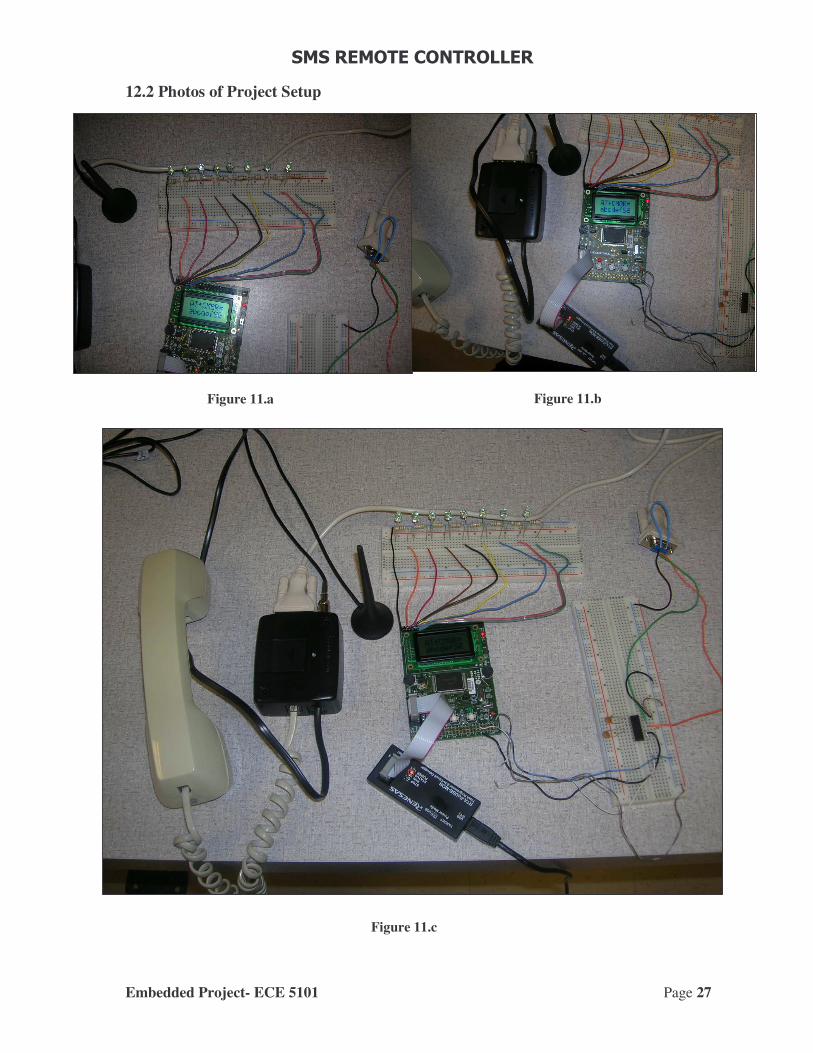
12.2 Photos of Project Setup
Figure 11.a Figure 11.b
Figure 11.c

�������������������
Embedded Project- ECE 5101 Page 28
13. Observations
• The manuals of modem (GM28) specified that the modem would communicate at a default baud rate of 9600bps, instead the modem was transmitting serially at 115200bps. But the SKP could transmit data serially without errors only at a maximum of 9600bps hence the modem had to be set to 9600bps every time it is turned on through AT commands (from the computer).
• The DB9 connector of the modem should be terminated with a null modem configuration, hence RTS (pin 7) and CTS (pin 8) of the modem was shorted.
• The modem can be completely controlled by the accompanying AT commands.
14. Precautions
• It should be taken care that the baud rate set initially should be changed to a lower value to (9600 baud) to communicate with the Renesas board. Because, there is bit error generated at higher baud rates and may cause generation of fault outputs.
• During the setup of the modem it should be noted that to send TO_IN to be high for about 0.2 sec to get the modem started.
• After inserting the SIM card wait for some time to initialize the SIM card. When the modem is ready the green LED on the modem starts blinking.
15. Conclusion
The experimental setup is able to read SMS from the SIM card (inside the modem GM28) and the modem checks for new SMS from the modem every 1second. The modem is able to send ambient temperature (reading the thermistor value from SKP) as SMS to the user every 15 minutes. As part of security, the SKP first verifies the received number from SMS text and then executes the control signal part of the SMS. The LEDs on the SKP indicate the status of the present ongoing function by the microcontroller.
Future scope:
• Switches on SKP can be assigned different functions like sending locally from SKP to the user.
• As per the requirement different type of sensors can be connected to the SKP and the data read can be sent to the user as SMS at regular intervals.
• As the SKP can receive data from external devices through its ports, the status of such devices can be transmitted to the user regularly through SMS.

�������������������
Embedded Project- ECE 5101 Page 29
16. References 1) Hardware and user manuals of the modem from Sony Ericsson GM28 2) http://developer.sonyericsson.com/getDocument.do?docId=65054 3) http://www.mobilegpsonline.com/downloads/GM28-29%20Datasheet%20R1G.pdf 4) http://www.mobilegpsonline.com/GSMJC01Spec.pdf 5) http://www.visualgsm.com/wire_sms_index.htm 6) http://en.wikipedia.org/wiki/Gsm 7) http://www.camiresearch.com/Data_Com_Basics/RS232_standard.html 8) http://www.beyondlogic.org/serial/serial.htm 9) http://www.dreamfabric.com/sms/ 10) http://www.nobbi.com/pduspy.htm 11) http://www.serasidis.gr/circuits/smscontroller/smscontroller.htm 12) http://www.gsm-modem.de/sms-text-mode.html
Related Documents