#13 1 Victor S. Frost Dan F. Servey Distinguished Professor Electrical Engineering and Computer Science University of Kansas 2335 Irving Hill Dr. Lawrence, Kansas 66045 Phone: (785) 864-4833 FAX:(785) 864-7789 e-mail: [email protected] http://www.ittc.ku.edu/ Specific Systems Cellular Part 1 #13 All material copyright 2006 Victor S. Frost, All Rights Reserved #13 2 Outline • Part 1 – Basic components – 3G – Overview of W-CDMA/UMTS – HSDPA/HSDUA • Part 2 – EV-DO overview – Case study: Mitigating scheduler-induced starvation in 3G wireless networks

Welcome message from author
This document is posted to help you gain knowledge. Please leave a comment to let me know what you think about it! Share it to your friends and learn new things together.
Transcript
#13 1
Victor S. FrostDan F. Servey Distinguished Professor
Electrical Engineering and Computer ScienceUniversity of Kansas2335 Irving Hill Dr.
Lawrence, Kansas 66045Phone: (785) 864-4833 FAX:(785) 864-7789
e-mail: [email protected]://www.ittc.ku.edu/
Specific Systems
CellularPart 1#13
All material copyright 2006Victor S. Frost, All Rights Reserved
#13 2
Outline
• Part 1– Basic components– 3G – Overview of W-CDMA/UMTS– HSDPA/HSDUA
• Part 2– EV-DO overview– Case study: Mitigating scheduler-induced
starvation in 3G wireless networks

#13 3
Model of Wireless Systems
Wireless network
Radio Station Subsystem
User Equipment
End User
Network Subsystem
External Networks, PSTN, Internet
OAM Subsystem
#13 4
Reference Model
From: Wireless Communications and Networking, V. K. Garg,Morgan Kaufmann, 2007
#13 5
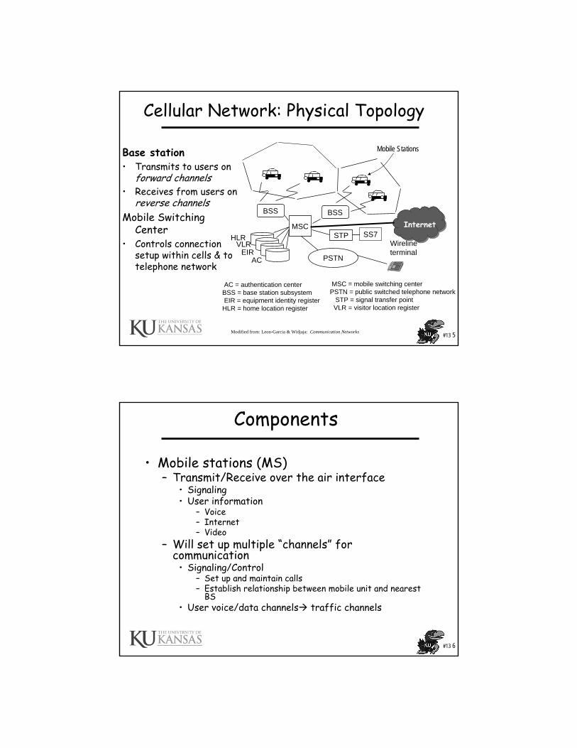
AC = authentication centerBSS = base station subsystemEIR = equipment identity register
HLR = home location register
Wirelineterminal
MSC
PSTN
BSS BSS
STP SS7HLRVLR
EIRAC
MSC = mobile switching centerPSTN = public switched telephone network
STP = signal transfer pointVLR = visitor location register
Cellular Network: Physical Topology
Base station• Transmits to users on
forward channels• Receives from users on
reverse channelsMobile Switching
Center• Controls connection
setup within cells & to telephone network
InternetInternet
Modified from: Leon-Garcia & Widjaja: Communication Networks
Mobile Stations
#13 6
Components
• Mobile stations (MS)– Transmit/Receive over the air interface
• Signaling• User information
– Voice– Internet– Video
– Will set up multiple “channels” for communication
• Signaling/Control– Set up and maintain calls– Establish relationship between mobile unit and nearest
BS• User voice/data channels traffic channels

#13 7
Components
• Base station (BS)– Transmit/Receive over the air interface
to multiple mobile stations– Terminates radio signals – Packages information for transport to a
controller (MSC) for routing– Sends information to Mobile Switching
Center
#13 8
Components
• Mobile Switching Center (MSC)– Connects to many BSs– Performs call set up– Provides routing functions– Typically associated with voice calls– Sometines called Mobile Telecommunications Switching Office (MST0)
• Home location register (HLR)– Wireless service provider (WSP) maintains a database
• Subscriber personal information, e.g., phone number, mobile identification number, electronic serial number (ESN) of phone
• Service Profile• Current location of subscriber
– One HLR may serve several MSCs• Visitor location register (VLR)
– Data base containing temporary information of subscribers– For subscribers away from home service area– VRL information retrieved from the HLR

#13 9
Channels• Communications between the UE and base station uses the
concept of Channels– Physical channels
• Time slots • Codes• Sets of subcarriers in OFDM• Frequencies
– Logical channels, e.g.,• Traffic channels (TCH) user information
– Data– Voice– Video
• Control channels (CCH) control and signaling• Cell Broadcast channels (CBCH) communicate to all UE in cell• These channels can be further divided, e.g.,
– Control channel has» Broadcast CH (BCH)» Common Control CH (CCCH)» Dedicated Control CH (DCCH)
• See more about logical channels later…….
#13 10
Process
• Registration– Turn on cell phone– BS continually transmit
signals on control channels– Cell phone scans for strongest
signal– Cell phone decodes control
signal to determine• System Id• Initial Tx power setting• Radio channels to use for
further communications• Cell phone registers with
network • Note as the MS moves it may
need to cancel registration in old area and re-register in new area

#13 11
Process
• Mobile Call Initiation– To make a call the
mobile keys the phone # and hits send
– Phone # transmitted over preselected control channel
– The BS relays information to the MSC
– MSC looks into the control message to get the # and processes the call, i.e., does the routing
#13 12
Process
• Call initiation to mobile– Call routed to home MSC– MSC checks HLR to
determine location of subscriber
– MSC has current visiting MSC stored in the HLR
– Home MSC communicates with the visiting MSC to rout the call
– The MSC sends a paging message to the paging message to BS
– The BS then send the paging message on to the subscriber on an assigned control (paging) channel

#13 13
Process
• Call accepted– MS sees the paging signal
and responds to the BS– The BS send response to
the MSC– The MSC sets up the call
to the BS– The MSC also assigns a air
interface channel for the BS to use for the call
– The MS communicates of the assigned channel
• Here the call is between two mobiles
• The communications is monitored for the ongoing call
#13 14
Process• Handoff (or handover)
– MS continually scans for control signals of BS
– Knowledge of the results of scans is used by MSC, e.g., power of control signal drops below some threshold
– Upon that event the MSC will initiate a handoff procedure
– Handoff procedures can be implemented transparent to the users, no interruption
– The handoff procedure tells the MS to use a specific channel to communicate with the new BS

#13 15
Process
• Handoffs– Hard: communications with old BS is terminated and a
new communications to a new BS is established– Soft:
• Soft: mobile station temporarily connected to more than one base station simultaneously
• Softer: mobile station temporarily connected to more than one sector of the same base station simultaneously
• Soft-softer: mobile station temporarily connected to more than one sector of the same base station and more than one base station simultaneously
• Provides diversity• Occurs at boundaries of sectors/cells
#13 16
Other Functions
• Call blocking– if all traffic channels busy
• Call termination– when user hangs up
• Call drop– when BS cannot maintain required signal strength

#13 17
Other Functions Power control CDMA
• Purpose– Removes near-far effect.– Mitigates fading, i.e., compensates changes in
propagation conditions.– In the system level
• decrease interference from other users• increase capacity of the system
• Uplink– Power control in uplink must make signal powers from
different users nearly equal at the BS in order to maximize the total capacity in the cell.
• Downlink– In downlink the power control must keep the signal at
minimal required level in order to decrease the interference to users in other cells.
#13 18
Other Functions Power control CDMA
• Types– Open loop
• Set initial power for MS• Each MS sets power based on individual
measurements• Coarse scale
– Closed loop• BS knows receive power from each MS• BS can tell each MS to set its power to achieve
system goals.• Fast power control can mitigate fast fading• Three steps:
– Transmission– Measurement– Feedback

#13 19
3G
• 1G: Analog Cellular Phones. Needs a modem. 9.6 kbps max.
• 2G: Digital Cellular Phones. No modem required. 19.3 kbps max.
• 2.5G: General Packet Radio Service (GPRS) 144kbps. Data only.
• 3G: Future high-speed data with Voice. 64 kbps to 2 Mbps.– W-CDMA/UMTS (Universal Mobile
Telecommunications System– CDMA2000
#13 20
Organizations
– 3GPP 3rd Generation Partnership Project.– 3GPP is responsible for writing and maintaining the
UMTS specifications– 3GPP has developed the Long Term Evolution (LTE)– American National Standards Institute (ANSI)
CDMA2000– WiMAX Forum” is an industry-led, not-for-profit
organization formed to certify and promote the compatibility and interoperability of broadband wireless products based upon the harmonized IEEE 802.16/ETSI HiperMAN standard” From http://www.wimaxforum.org/home/
– Internet Engineering Task Force (IETF)
Modified from: www.ccs.neu.edu/home/rraj/G250Projects/NachiketMehta.ppt

#13 21
3G- Advantages3G phones: The promise• Improved digital voice communications • Larger Bandwidth – Higher Data rate• Greater subscriber capacity • Fast packet-based data services like e-mail, short
message service (SMS), and Internet access at broadband speeds.
• Most carriers also expect consumers to want: – location services – interactive gaming – streaming video – home monitoring and control – and who knows what else, while being fully mobile
anywhere in the world.
Modified from: www.ccs.neu.edu/home/rraj/G250Projects/NachiketMehta.ppt
#13 22
3G Capabilities• Voice quality comparable to the public switched
telephone network• 144 Kbps- user in high-speed motor vehicles• 384 Kbps- pedestrians standing or moving slowly
over small areas• Target up to 2 Mbps- fixed applications like office
use• Symmetrical/asymmetrical data transmission
rates• Support for both packet switched and circuit
switched data services like Internet Protocol (IP) traffic and real time video
Modified from: www.ccs.neu.edu/home/rraj/G250Projects/NachiketMehta.ppt

#13 23
Technologies
• 3G is superior to the other digital standards like:-– GSM (Global System for Mobile) communications standard used
worldwide – And IS-136 TDMA standard used primarily in North America. – IS-95 CDMA systems
• 3G Technologies:-– WCDMA or UMTS-FDD (Universal Mobile Telecommunications
System - Frequency Division Duplex)---Direct Sequence Spread Spectrum
– CDMA2000 - 1x-EvDO/EvDV---Multi carrier– UMTS – TDD (Time Division Duplex) or TD-SCDMA (Time Division -
Synchronous Code Division Multiple Access) ---Time Code– CDMA2000 and WCDMA or UMTS-FDD have similar architectures
Modified from: www.ccs.neu.edu/home/rraj/G250Projects/NachiketMehta.ppt
#13 24
Evolution Paths
2.5G2G 3G
cdmaOneIS-95A
TDMA
cdmaOneIS-95B Cdma2000 1X
Cdma20001xEV-DV
Cdma20001xEV-DO
GSMGPRS
EDGE WCDMA
GSM Map Core Network
IS-41 Core Network
2.5G2G 3G
cdmaOneIS-95A
TDMA
cdmaOneIS-95B Cdma2000 1X
Cdma20001xEV-DV
Cdma20001xEV-DO
GSMGPRS
EDGE WCDMA
GSM Map Core Network
IS-41 Core Network
Modified from: www.ccs.neu.edu/home/rraj/G250Projects/NachiketMehta.ppt
#13 25
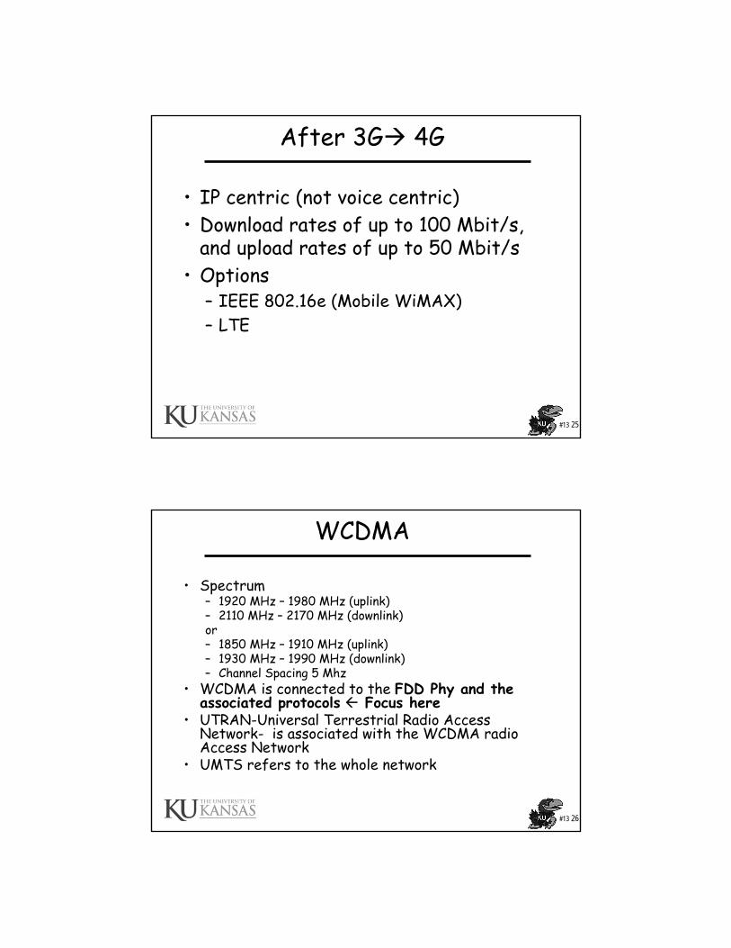
After 3G 4G
• IP centric (not voice centric)• Download rates of up to 100 Mbit/s,
and upload rates of up to 50 Mbit/s• Options
– IEEE 802.16e (Mobile WiMAX)– LTE
#13 26
WCDMA
• Spectrum– 1920 MHz – 1980 MHz (uplink)– 2110 MHz – 2170 MHz (downlink)or– 1850 MHz – 1910 MHz (uplink)– 1930 MHz – 1990 MHz (downlink)– Channel Spacing 5 Mhz
• WCDMA is connected to the FDD Phy and the associated protocols Focus here
• UTRAN-Universal Terrestrial Radio Access Network- is associated with the WCDMA radio Access Network
• UMTS refers to the whole network

#13 27
UMTS-FDD / WCDMA
• Wideband Direct Sequence Code Division Multiple Access
• Does not assign a specific frequency to each user. Instead every channel uses the full available spectrum.
• Individual conversations are encoded with a pseudo-random digital sequence
Ref: http://www.umtsworld.com/technology/overview.htm
#13 28
WCDMA Parameters
4 to 512Downlink Spreading Factor
4 to 256Uplink Spreading Factor
Open and fast close loop (1.6 KHz)Power Control
2560chips (Max. 2560 bits)No. of chips/slot
15No. of slots/frame
10 ms (38400 chips)Frame Length
3.84 McpsChip Rate
Direct SpreadForward RF Channel Structure
5 MHzChannel B.W
#13 29
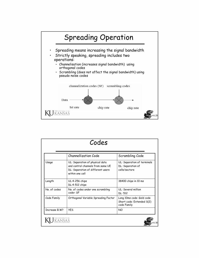
Spreading Operation• Spreading means increasing the signal bandwidth• Strictly speaking, spreading includes two
operations:– Channelisation (increases signal bandwidth) using
orthogonal codes– Scrambling (does not affect the signal bandwidth) using
pseudo noise codes
#13 30
Codes
NOYESIncrease B.W?
Long 10ms code: Gold codeShort code: Extended S(2) code Family
Orthogonal Variable Spreading FactorCode Family
UL: Several millionDL: 512
No. of codes under one scrambling code= SF
No. of codes
38400 chips in 10 msUL:4-256 chipsDL:4-512 chips
Length
UL: Separation of terminalsDL: Separation ofcells/sectors
UL: Separation of physical dataand control channels from same UEDL: Separation of different userswithin one cell
Usage
Scrambling CodeChannellization Code

#13 31
UMTS Architecture
Modified from: M. D. Yacoub, Wireless Technology, Protocols, Standards, and Techniques, CRC Press, 2002
Cell site
Access Network
Core Network (CN)
User Equipment
External Networks
#13 32
UMTS Architecture
From: Geert Heijenk, wwwhome.cs.utwente.nl/~heijenk/mwn/slides/Lecture-5%206%20slides%20per%20page.pdf
#13 33
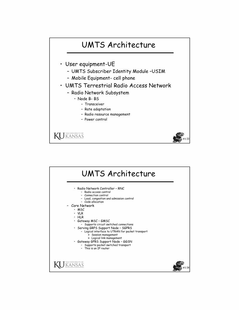
UMTS Architecture
• User equipment-UE– UMTS Subscriber Identity Module –USIM– Mobile Equipment- cell phone
• UMTS Terrestrial Radio Access Network– Radio Network Subsystem
• Node B- BS– Transceiver– Rate adaptation– Radio resource management– Power control
#13 34
UMTS Architecture• Radio Network Controller – RNC
– Radio access control– Connection control– Load, congestion and admission control– Code allocation
– Core Network• MSC• VLR• HLR• Gateway MSC – GMSC
– Supports circuit switched connections• Serving GRPS Support Node – SGPRS
– Logical interface to UTRAN for packet transport» Session management» Logical link management
• Gateway GPRS Support Node – GGSN– Supports packet switched transport– This is an IP router

#13 35
UMTS Protocol Architecture - User Plane
From: Geert Heijenk, wwwhome.cs.utwente.nl/~heijenk/mwn/slides/Lecture-5%206%20slides%20per%20page.pdf
FP= Framing Protocol GTP-U= GPRS Tunneling Protocol-User PDCP =Packet Data convergence Protocol
#13 36
UMTS Protocol Stack• Radio Resource
Control-RRC• Broadcast/mulitcast
control- BMC• Packet Data
convergence Protocol- PDCP– Header compression
Modified from: M. D. Yacoub, Wireless Technology, Protocols, Standards, and Techniques, CRC Press, 2002
#13 37
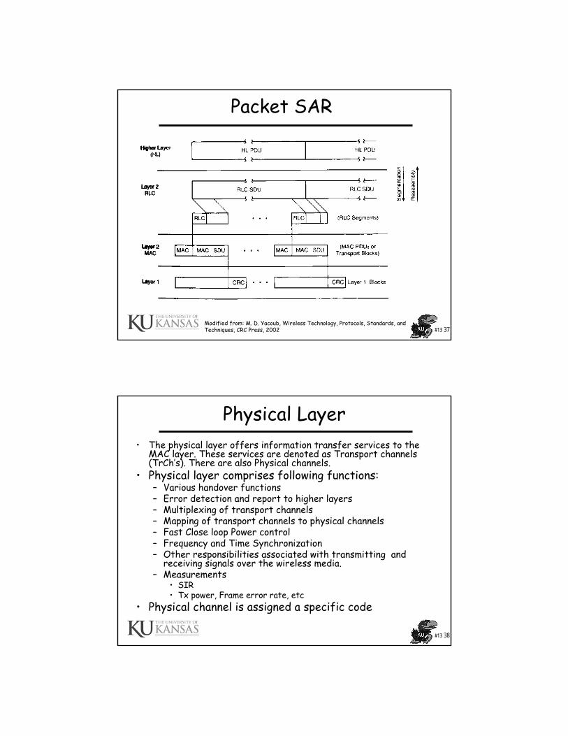
Packet SAR
Modified from: M. D. Yacoub, Wireless Technology, Protocols, Standards, and Techniques, CRC Press, 2002
#13 38
Physical Layer• The physical layer offers information transfer services to the
MAC layer. These services are denoted as Transport channels (TrCh’s). There are also Physical channels.
• Physical layer comprises following functions:– Various handover functions– Error detection and report to higher layers– Multiplexing of transport channels– Mapping of transport channels to physical channels– Fast Close loop Power control– Frequency and Time Synchronization– Other responsibilities associated with transmitting and
receiving signals over the wireless media.– Measurements
• SIR• Tx power, Frame error rate, etc
• Physical channel is assigned a specific code

#13 39
Physical Layer
From: Geert Heijenk, wwwhome.cs.utwente.nl/~heijenk/mwn/slides/Lecture-5%206%20slides%20per%20page.pdf
#13 40
Transport & Physical Channels
Synchronization channel SCHCommon pilot channel CPICHAcquisition indication channel AICHPaging indication channel PICHCPCH Status indication channel CSICHCollision detection/Channel assignment indicator channel CD/CA-ICH
Signaling physical channels
Physical downlink shared channel PDSCH(DL) Downlink shared channel DSCH
Secondary common control physical channel S-CCPCH
(DL) Forward access channel FACH(DL) Paging channel PCH
Primary common control physical channel P-CCPCH
(DL) Broadcast channel BCH
Physical common packet channel PCPCH(UL) Common packet channel CPCH
Physical random access channel PRACH(UL) Random Access Channel RACH
Dedicated Physical Data Channel DPDCHDedicated Physical Control Channel DPCCH
(UL/DL) Dedicated Channel DCH
Physical ChannelTransport Channel

#13 41
UMTS FDD frame structure
From: Geert Heijenk, wwwhome.cs.utwente.nl/~heijenk/mwn/slides/Lecture-5%206%20slides%20per%20page.pdf
#13 42
MAC Layer
• The MAC layer offers data transfer to RLC and higher layers.
• The MAC layer comprises the following functions:– Selection of appropriate Transport Format (TF), basically bit
rate, within a predefined set, per information unit delivered to the physical layer
– Service multiplexing on RACH, FACH, and dedicated channels– Priority handling between ‘data flows’ of one user as well as
between data flows from several users—the latter being achieved by means of dynamic scheduling
– Access control on RACH– Address control on RACH and FACH– Contention resolution on RACH– Traffic volume measurements

#13 43
RRC Layer• The RRC layer offers the core network the following
services:– General control service, which is used as an information
broadcast service– Notification service, which is used for paging and notification
of a selected UEs– Dedicated control service, which is used for
establishment/release of a connection and transfer of messages using the connection.
• The RRC layer comprises the following functions:– Broadcasting information from network to all UEs– Radio resource handling (e.g., code allocation, handover,
admission control, and measurement reporting/control)– QoS Control– UE measurement reporting and control of the reporting– Power Control, Encryption and Integrity protection
#13 44
RLC Layer• The RLC layer offers the following services to the higher layers:
– Layer 2 connection establishment/release– Transparent data transfer, i.e., no protocol overhead is appended to
the information unit received from the higher layer– Assured and un assured data transfer
• The RLC layer comprises the following functions:– Segmentation and assembly– Transfer of user data– Error correction by means of retransmission optimized for the
WCDMA physical layer– Sequence integrity-In sequence delivery (used by at least the
control plane)– Duplicate detection– Flow control– Ciphering
• Encryption of user and signaling traffic over air interface• SIM provides key information• Terminates at the RNC

#13 45
RLC Layer-Modes• Transparent-TM
– No header attached– SAR– SDU discard
• Delete SDU if not sent before timer expires– Used for
• Voice• Some signaling
• Unacknowledged (UM)– Header with Seq number– SAR– Pad– SDU discard– Provides some reliability
• Acknowledged Mode (AM)– Siding window-ARQ– Selective repeat
#13 46
RLC Layer
From, Juan J. Alcaraz, Fernando Cerdan, and Joan García-Haro,“Optimizing TCP and RLC Interaction in the
UMTS Radio Access Network”, IEEE Network • March/April 2006
#13 47
UE-Call states
• Designed to – Take advantage of bursty nature of data– Save battery power– Maintains logical session and tracks
mobility when appropriate– Releases dedicated resources to
increase overall capacity– Put UE to sleep
#13 48
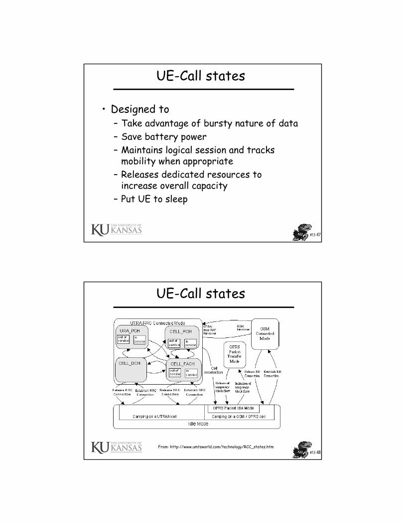
UE-Call states
From: http://www.umtsworld.com/technology/RCC_states.htm

#13 49
UE-Call states
• Idle mode– No active session– UE monitors Paging
CH– Sleeps between
paging cycles
From: http://www.umtsworld.com/technology/RCC_states.htm
#13 50
UE-Call states
• CELL_DCH state (Dedicated)– A dedicated physical channel
is allocated to the UE in uplink and downlink.
– The UE is known on cell level – Dedicated transport channels,
downlink and uplink (TDD) shared transport channels, and a combination of these transport channels can be used by the UE.
– Call types• Circuit Switched always in
this state• Packet Switched in this state
if transferring large volume of data
Modified rom: http://www.umtsworld.com/technology/RCC_states.htm
#13 51
UE-Call states
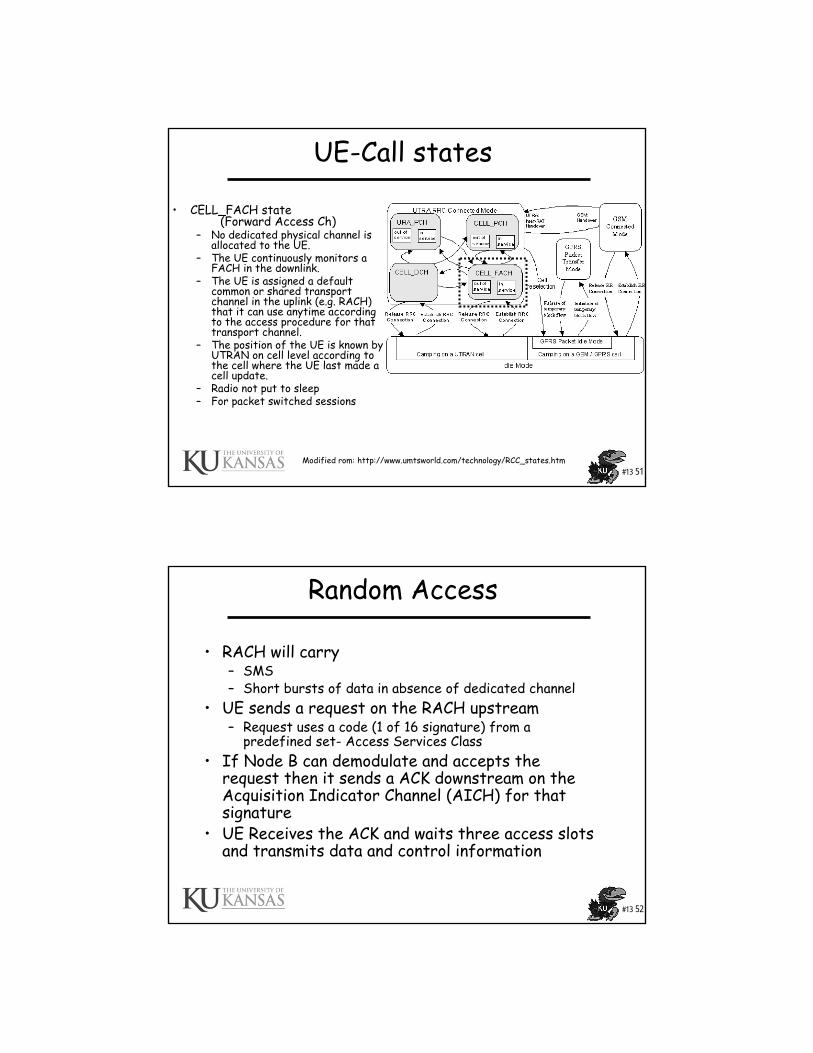
• CELL_FACH state(Forward Access Ch)
– No dedicated physical channel is allocated to the UE.
– The UE continuously monitors a FACH in the downlink.
– The UE is assigned a default common or shared transport channel in the uplink (e.g. RACH) that it can use anytime according to the access procedure for that transport channel.
– The position of the UE is known by UTRAN on cell level according to the cell where the UE last made a cell update.
– Radio not put to sleep– For packet switched sessions
Modified rom: http://www.umtsworld.com/technology/RCC_states.htm
#13 52
Random Access
• RACH will carry– SMS – Short bursts of data in absence of dedicated channel
• UE sends a request on the RACH upstream– Request uses a code (1 of 16 signature) from a
predefined set- Access Services Class• If Node B can demodulate and accepts the
request then it sends a ACK downstream on the Acquisition Indicator Channel (AICH) for that signature
• UE Receives the ACK and waits three access slots and transmits data and control information

#13 53
Random Access
• If request initially fails no ACK– UE selects new code– Increases the power and retransmits– That is the UE persist in trying to
transmit for a while• UE gives up and then backoffs if:
– Runs out of codes or– Runs out of power or– Node B tells it to go away with a NACK
#13 54
Packet Access-Concept
• At “low loads” use CELL_FACH state and transmit over RACH
• At “high loads” assign dedicated resources (channels) for packet transmission-CELL-DCH state

#13 55
UE-Call states
• CELL_PCH state (Paging Ch)– No dedicated physical channel
is allocated to the UE.– The UE selects a PCH with
the algorithm, and uses DRX for monitoring the selected PCH via an associated PICH.
– No uplink activity is possible.– Sleep between pages– A logical session is still up– The position of the UE is
known by UTRAN on cell level according to the cell where the UE last made a cell update in CELL_FACH state.
Modified rom: http://www.umtsworld.com/technology/RCC_states.htm
DRX= Discontinuous reception . The time between the transmission of successive paging indicator messages is the DRX cycle length. The DRX mode saves power.
#13 56
UE-Call states
• URA_PCH State – No dedicated channel is
allocated to the UE.– The UE selects a PCH with
the algorithm, and uses DRX for monitoring the selected PCH via an associated PICH.
– No uplink activity is possible.– The location of the UE is
known on UTRAN Registration area (URA) level according to the URA assigned to the UE during the last URA update in CELL_FACH state.
– Similar to CELL_PCH state only location known at the URA level
Modified rom: http://www.umtsworld.com/technology/RCC_states.htm
URA covers multiple cells

#13 57
Power Control-PC• Fast Closed Loop PC – Inner Loop PC
– Feedback information.– Uplink PC is used for near-far problem. Downlink PC is to
ensure that there is enough power for mobiles at the cell edge.
• Two special cases for fast closed loop PC:– Soft handover:- how to react to multiple power control
commands from several sources. At the mobile, a “power down” command has higher priority over “power up” command.
– Compressed mode:- Large step size is used after a compressed frame to allow the power level to converge more quickly to the correct value after the break.
#13 58
Power Control
• Open loop PC– No feedback information.– Make a rough estimate of the path loss by
means of a downlink beacon signal.– Provide a coarse initial power setting of the
mobile at the beginning of a connection.– Apply only prior to initiating the
transmission on RACH or CPCH.

#13 59
Packet Access in WCDMA
• Packet allocations performed in the RNC by the packet scheduler (PS)– Time, code or power– Bit rates– Holding times– Channel selection
• PS allocates traffic to specific channels– Common– Delectated
• RNC can decide when and how to send packets based on type of packet traffic,
– Conversational class -> real-time connection, performed between human users, really low delay, nearly symmetric, e.g., speech
– Streaming class -> real-time connection, transferring data as a steady and continuous, low delay, asymmetric, e.g., video
– Interactive class -> non-real-time packet data, response requested from other end-user, reasonable round-trip delay, e.g., Web browsing
– Background class -> non-real-time packet data, no immediate action expected, less sensitive to delivery time, e.g., e-mail
• RNC can assign a packet to a specific channel
Modified from: P. Chong, www.comlab.hut.fi/opetus/238/lecture9_PacketAccess.pdf
#13 60
Packet Access in WCDMA• Common channels - RACH in the uplink and FACH in the downlink
– One or few RACH or FACH per sector– Low setup time– No feedback channel -> no fast closed loop power control, no soft
handover, use fixed power– Poor link-level radio performance and generated more interference– Suitable for small data amounts
• Common packet channels - CPCH in the uplink– Bit rate can be high– Support fast power control– Suitable for small or medium data amounts
• Dedicated Channel - DCH in the uplink and downlink– Use fast power control and soft handover– Better link-level radio performance and less interference– Longer setup time– Up to 2 Mbps– Suitable for large data amounts– Not suitable for bursty data– In case of changing bit rate in the downlink, the downlink orthogonal
code is reserved according to maximum bit rate.
From: P. Chong, www.comlab.hut.fi/opetus/238/lecture9_PacketAccess.pdf

#13 61
Packet Access in WCDMA• In WCDMA packet scheduling algorithms can be done in two
ways, in a time or code division manner.• Time division scheduling
– one user is allocated a channel at a time (10 ms frame)– all available capacity can be allocated to that user– high data rate for a short period of time– increase more users, each user has to wait longer
• Advantages of time division scheduling – high bit rate required less energy per bit– less interference– shorter delay due to high bit rate
• Disadvantages– high unused physical resources due to short transmission time
and relatively long set up and release time– high variations in the interference levels due to high bit rate
and bursty traffic– limited uplink range of high bit rate due to mobile’s limited
transmission power
From: P. Chong, www.comlab.hut.fi/opetus/238/lecture9_PacketAccess.pdf
#13 62
Packet Access in WCDMA
• Code division scheduling– many users are allocated the channels simultaneously– the capacity is shared with all users– low data rate for a long period of time– increase more users, each user’s bit rate is decreased
• Advantages– resources are in full usage due to longer transmission
time– small variation in interference level– longer uplink range due to lower bit rate
• Disadvantages– longer transmission delay due to low bit rate– high interference due to high energy per bit– low total throughput
From: P. Chong, www.comlab.hut.fi/opetus/238/lecture9_PacketAccess.pdf

#13 63
Packet Access in WCDMA
• Time division is normally used with shared channels and code division is normally used with dedicated channels.
From: P. Chong, www.comlab.hut.fi/opetus/238/lecture9_PacketAccess.pdf
#13 64
Packet Access in WCDMA
• Transmission Power-based Scheduling– The bit rate allocated to each packet data users could be
based on required transmission power• Users close to the BS requires less transmission
power and can get a higher bit rate, whereas users at the cell edge could get lower bit rate
• Advantages– minimize the average power sent per bit– less interference– increase the throughput
• • Disadvantages– accurate power estimation– unfair resource allocation
From: P. Chong, www.comlab.hut.fi/opetus/238/lecture9_PacketAccess.pdf

#13 65
HSDPA & Enhance Uplink• HSDPA = High Speed Downlink Packet
Access
From: Stefan Parkvall, Eva Englund, Magnus Lundevall, and Johan Torsner, “Evolving 3G Mobile Systems: Broadband and Broadcast Services in WCDMA”, IEEE Communications Magazine, February 2006
#13 66
HSDPA & Enhance Uplink
• Remember it is better (more efficient) to have a large number of users sharing a single server
• This lead to a desire to have fast allocation of shared resources
• Downlink resources– Transmit power (interference to other cells)– Channelization code
• Uplink resources– Interference at the BS
• Other fast mechanisms– Fast scheduling– Fast ARQ (hybrid ARQ) (this is in addition to the RLC AM)
• To be fast mechanisms must be close to the air interface– HSDPA put the mechanisms in BS (Node B) not at the RNC

#13 67
HSDPA & Enhance Uplink• UTRAN Architecture with HSDPA
and enhanced uplink
From: Stefan Parkvall, Eva Englund, Magnus Lundevall, and Johan Torsner, “Evolving 3G Mobile Systems: Broadband and Broadcast Services in WCDMA”, IEEE Communications Magazine, February 2006
#13 68
HSDPA & Enhance Uplink
• Changes– Removed
• Variable spreading factor• Fast power control
• Added– shorter radio frame enable quick response to changes– new high-speed downlink channels
• High-speed Shared Channel HS-DSCH• High-speed Shared Control Channel HS-SCCH• High-speed Dedicated Phy Control Channel HS-DPCCH
– use of 16 QAM modulation in addition to QPSK modulation– fixed spreading factor – code multiplexing combined with time multiplexing– fast link adaptation using adaptive modulation and coding (AMC)– use of hybrid automatic-repeat-request (HARQ) incremental redundancy– medium access control (MAC) scheduling function moved to Node-B
(WCDMA packet scheduling was done in the RNC)
From: Agilent, Applications note:Concepts of High Speed Downlink Packet Access:Bringing Increased Throughput and Efficiency to W-CDMA

#13 69
HSDPA & Enhance Uplink
• Gain in Performance
From: WCDMA Evolved:High Speed Downlink Packet Access Mechanismsand Capabilities, Alexander Wang www.pcca.org/standards/architecture/hsdpa.pdf
240 kb/s
840 kb/s
1950 kb/s
#13 70
HSDPA
• Shared transmission mechanism• Definition of a new “channel”• High-speed downlink shared channel (HS-DSCH) • The HS-DSCH is dynamically used to transmit to
individual users– Supports link adaptation, hybrid ARQ and scheduling– Always associated with a DPCH– Never in soft handover– Fixed spread factor– Mapped to one or several channelization codes
• An associated control channel is also defined • High Speed- shared control channel (HS-SCCH)

#13 71
HSDPA
• New frame structure– Five subframes/W-CDMA
frame– User data can be assigned
on a subframe basis– System can adjust in 2ms– Each subframe is a
transmission time interval (TTI) = 2ms
*From: Agilent, Applications note:Concepts of High Speed Downlink Packet Access:Bringing Increased Throughput and Efficiency to W-CDMA
*
#13 72
HSDPA• HS-DSCH structure both Code sharing and TDM• Spread Factor = 16 fixed• 15 different spreading codes• UE can send on multiple codes in a TTI• A difference with W-CDMA is that the shared
resource is also in the time domain
From: Stefan Parkvall, Eva Englund, Magnus Lundevall, and Johan Torsner, “Evolving 3G Mobile Systems: Broadband and Broadcast Services in WCDMA”, IEEE Communications Magazine, February 2006
10 out of 16 codes
used by one user

#13 73
HSDPA
• Another view
*From: Agilent, Applications note:Concepts of High Speed Downlink Packet Access:Bringing Increased Throughput and Efficiency to W-CDMA
Spreading Code
*
#13 74
HSDPA• Link Adaptation
– Remember the fast power control is commonly used to:• Maintain constant Energy/Noise ratio• Reduce effect of fading
– This is suitable for constant bit rate transmissions– Here bit rate can change introducing delay, delay is ok– Changing bit rate can also maintain constant Energy/Noise
while keeping the tx power constant – The is called link rate adaptation
*From: WCDMA Evolved:High Speed Downlink Packet Access Mechanismsand Capabilities, Alexander Wang www.pcca.org/standards/architecture/hsdpa.pdf
*Notes:•Resources spectrum, time, power, here total BW used•In DS total power limited my interference to other cells

#13 75
HSDPA
– Bit rate changed by using• QPSK (2 bits per symbol time)Or• 16 QAM (4 bits per symbol time)
– Modulation selected every 2 ms– Number of codes assigned selected every 2 ms– (Bit rate/code) * # codes = bit rate– Theoretical maximum
• Largest transport block = 27,952 bits in 2ms = 13.9Mb/s consumes most of cell’s resources for one user
• 1 – 2 Mb/s closer to achievable under real conditions
#13 76
HSDPA• To assign a modulation and bit rate/code
the BS (Node B) needs some link quality feed back from the UE
• Each UE regularly transmits Channel Quality Indicator (CQI) to the BS– CQI comes from a CIR measurement and
current Spreading Factor– Configurable– Can be every 2 ms
• CQI (0-30) each mapping into a modulation, SF, etc.
• Note the “better” UE’s can ask for higher CQI’s, e.g., a UE with interference suppression

#13 77
HSDPA
• Scheduling– The scheduler decides which user should
get access to each TTI – CQI provides input into a Scheduler
• Proportional Fair (PF) Scheduler can be used• Implementation specific
#13 78
HSDPA
• Hybrid ARQ (HARQ)– Uses incremental redundancy (IR)– Note when UE close the BS the number
of spreading codes limits rate not power, so likely receive first transmission
– At greater distances move from BS see more errors, IR will require additional transmission but not many.
– HARQ only retransmit upon an ACK or NACK

#13 79
HSDPA
From: Mohamad Assaad, Zeghlache Djamal TCP Performance Over UMTS-HSDPA Systems, CRC Press, 2007
GTP-U = GPRS tunneling protocol: GTP-U is used for carrying user data within the GPRS core network and between the Radio Access Network and the core network.
#13 80
HSDPA
• Key concepts– Shared Channel Transmission (via codes)– Higher Order Modulation– Short Transmission Time Interval (2 ms)– Fast Hybrid ARQ with Soft Combining– Fast Link Adaptation– Fast Radio Channel Dependent Scheduling– HSDPA has a theoretical maximum of 14 Mb/s.

#13 81
Enhance Uplink (HSUPA)
• Enhanced dedicated channel (E-DCH)• Needs power control for near-far problem so no
higher order modulation can not trade off data rate for E/N
• Shared resource is CDMA interference at the BS (Node B) desire to maintain a target interference level at Node B
• Interference a function of– UE SF data rate (higher rate more interference)– UE transmission time
• HSUPA has a theoretical maximum of 5.76 Mb/s.
#13 82
Enhance Uplink (HSUPA)
• A scheduler is used to control – When each UE transmits– What rate each UE transmits at
• Goal of the scheduler is to assign resource to those UEs with data to send
• BS (Node B) sends scheduling grants• There are two types of grants:
– The Absolute Grants provide an absolute limitation of the maximum amount of UL resources the UE may use;
– The Relative Grants increase or decrease the resource limitation compared to the previously used value;

#13 83
Enhance Uplink (HSUPA)
• Method 1– UE sends scheduling requests with
• Available Tx power• UE buffer state• Priority of buffered data (to provide QoS)• BS knows via signaling
– Instantaneous interference level– All requests
» Buffer size» Priority of waiting traffic
• Then determines which grants to sent
#13 84
Enhance Uplink (HSUPA)
Adapted from: Nick Hallam-Baker, Challenges of the Evolving 3G Technology,http://www.evaluationengineering.com/archive/articles/0406/0406challenges.asp
• Method 2– UE send a Happy Bit
every 2 ms– Node B sends a grant in
the form of a proportion of power that maybe sent on the uplink
– This corresponds to a maximum date rate
#13 85
Enhance Uplink (HSUPA)
• This resource allocation scheme more efficient for bursty traffic allowing more liberal connection admission control.
• HARQ is also used on the uplink
#13 86
References #12• Attar, R., et al., Evolution of cdma2000 cellular networks:
multicarrier EV-DO. Communications Magazine, IEEE, 2006. 44(3): p. 46-53.
• Bhushan, N., et al., CDMA2000 1xEV-DO revision a: a physical layer and MAC layer overview. Communications Magazine, IEEE, 2006. 44(2): p. 37-49.
• Ekstrom, H., et al., Technical solutions for the 3G long-term evolution. Communications Magazine, IEEE, 2006. 44(3): p. 38-45.
• Guangyi, L., et al., Evolution map from TD-SCDMA to FuTURE B3G TDD. Communications Magazine, IEEE, 2006. 44(3): p. 54-61.
• Parkvall, S., et al., Evolving 3G mobile systems: broadband and broadcast services in WCDMA. Communications Magazine, IEEE, 2006. 44(2): p. 30-36.
• Sanjiv Nanda, K.B., Sarath Kumar,, Adaptation Techniques in Wireless Packet Data Services. IEEE Communications Magazine, 2000(1): p. 54-64.
• Sarikaya, B., Packet mode in wireless networks: overview of transition to third generation. Communications Magazine, IEEE, 2000. 38(9): p. 164-172.
• Yavuz, M., et al., VoIP over cdma2000 1xEV-DO revision A.Communications Magazine, IEEE, 2006. 44(2): p. 50-57.
#13 87
References #12• Leon-Garcia & Widjaja: Communication Networks, McGraw
Hill, 2004• www.ccs.neu.edu/home/rraj/G250Projects/NachiketMehta.p
pt• M. D. Yacoub, Wireless Technology, Protocols, Standards,
and Techniques, CRC Press, 2002• Geert Heijenk,
wwwhome.cs.utwente.nl/~heijenk/mwn/slides/Lecture-5%206%20slides%20per%20page.pdf
• Juan J. Alcaraz, Fernando Cerdan, and Joan García-Haro, “Optimizing TCP and RLC Interaction in the UMTS Radio Access Network”, IEEE Network • March/April 2006
• http://www.umtsworld.com/technology/RCC_states.htm• P. Chong,
www.comlab.hut.fi/opetus/238/lecture9_PacketAccess.pdf• Agilent, Applications note: Concepts of High Speed Downlink
Packet Access: Bringing Increased Throughput and Efficiency to W-CDMA
#13 88
References #12
• Alexander Wang , WCDMA Evolved: High Speed Downlink Packet Access Mechanisms and Capabilities, www.pcca.org/standards/architecture/hsdpa.pdf
• Mohamad Assaad, Zeghlache Djamal TCP Performance Over UMTS-Hsdpa Systems, CRC Press, 2007
• HSUPA• Enhanced Uplink DCH(HSUPA), http://www.nec-
mobilesolutions.com/infrastructures/solution/hsupa.html• Nick Hallam-Baker, Challenges of the Evolving 3G
Technology, http://www.evaluationengineering.com/archive/articles/0406/0406challenges.asp
Related Documents