Piston pump unit Product series KFG For fluid grease and grease For use in SKF MonoFlex and SKF ProFlex centralized lubrication systems Features: Delivery rates: 0.8 to 15 cm³ / min • Fluids delivered: Fluid grease and grease • Reservoir capacities: 2 to 20 kg • Patented grease follower plate system • for position-independent application (e.g. rotary application in wind energy systems) Integrated fill level monitoring • Control unit that can be integrated • For us in vehicles, Industrial and wind • energy systems Piston pump units for vehicle applications • with E1 (KBA) certification Advantages: Reliable: due to sturdy materials, very • durable components and designs for extreme conditions (with positively driven pump elements) Application-oriented: individual designs • through user-friendly product customizer Versatile: can be used as a single line • (SKF MonoFlex) and as a progressive pump (SKF ProFlex) Safe: through fill level monitoring, • lubrication system monitoring, pressure relief and control unit

12649 en Piston Pump Unit - Product Series KFG
Nov 30, 2015
Piston Pump
Welcome message from author
This document is posted to help you gain knowledge. Please leave a comment to let me know what you think about it! Share it to your friends and learn new things together.
Transcript

Piston pump unit
Product series KFGFor fluid grease and greaseFor use in SKF MonoFlex and SKF ProFlex centralized lubrication systems
Features:
Delivery rates: 0.8 to 15 cm³ / min•
Fluids delivered: Fluid grease and grease•
Reservoir capacities: 2 to 20 kg•
Patented grease follower plate system •
for position-independent application
(e.g. rotary application in wind energy
systems)
Integrated fill level monitoring•
Control unit that can be integrated•
For us in vehicles, Industrial and wind •
energy systems
Piston pump units for vehicle applications •
with E1 (KBA) certification
Advantages:
Reliable: due to sturdy materials, very •
durable components and designs for
extreme conditions (with positively
driven pump elements)
Application-oriented: individual designs •
through user-friendly product customizer
Versatile: can be used as a single line •
(SKF MonoFlex) and as a progressive
pump (SKF ProFlex)
Safe: through fill level monitoring, •
lubrication system monitoring,
pressure relief and control unit
PU
B L
S/P
2 1
2649 E
N · 1
-3030-EN
! Important information on product usageAll products from SKF may be used only for their intended purpose as described in this
brochure and in any instructions. If operating instructions are supplied with the products, they must be read and followed.
Not all lubricants are suitable for use in centralized lubrication systems. SKF does offer an inspection service to test customer supplied lubricant to determine if it can be used in a central-ized system. SKF lubrication systems or their components are not approved for use with gases, liquefied gases, pressurized gases in solution and fluids with a vapor pressure exceeding normal atmospheric pressure (1 013 mbar) by more than 0,5 bar at their maximum permissible temperature.
Hazardous materials of any kind, especially the materials classified as hazardous by European Community Directive EC 67/548/EEC, Article 2, Par. 2, may only be used to fill SKF centralized lubrication systems and components and delivered and/or distributed with the same after consulting with and receiving written approval from SKF.
2

PU
B L
S/P
2 1
2649 E
N · 1
-3030-EN
KFG piston pump unit
Table of contents
OverviewSKF system family Field of application Page
SKF MonoFlex SKF ProFlex Rotary Industry Vehicle
Control unit Without internal and external control unit – • • • • 8Internal control unit IG502-2-I – • • • • 8Internal control unit LC502 • • • • • 8
Reservoir capacity[kg]
2 • • – • • 74 • • • – – 76 • • • • • 78 • • • – – 710 • • • • • 712 • • • – – 715 • • • • • 720 • • – • • 7
Pump element With positively driven piston • • • • • 6With spring-return piston • • • • • 6
Fill level indicator
None • • • • • 7With mechanical fill level switch • • – • • 7With mechanical fill level switch and signal smoothing • • – • • 7With capacitive proximity switch • • – • – 7With cylinder switch • • • – – 7
Metered quantity 0.8–5 cm³/min (per outlet) • • • • • 6
Filling Lubricant nipple • • – • • 6Socket for filling cylinder • • – • • 9Filler coupling on reservoir cover • • • – – 7
Valves None – • • • • 9Relief valve incl. pressure regulating valve • – • • • 9Pressure regulating valve – • • • • 9
Elect. connection 12 V DC • • – – • 624 V DC • • • • • 6230 V AC (90–264 V AC ) • • • • – 6
Productselection table
Product selection table . . . . . . . . . . . . . . . . . . . . . . . . . . . . . 3
Introduction . . . . . . . . . . . . . . . . . . . . . . . . . . . . . . . . . . . . . . 4
Fields of application . . . . . . . . . . . . . . . . . . . . . . . . . . . . . . . . 4
Functional description in
SKF centralized lubrication systems . . . . . . . . . . . . . . . . . . . 5
Main components . . . . . . . . . . . . . . . . . . . . . . . . . . . . . . . . 6–9
Designs . . . . . . . . . . . . . . . . . . . . . . . . . . . . . . . . . . . . . . . . . 10
Product customizer . . . . . . . . . . . . . . . . . . . . . . . . . . . . . . . 11
Dimensioned drawings . . . . . . . . . . . . . . . . . . . . . . . . . . 12–13
Technical data . . . . . . . . . . . . . . . . . . . . . . . . . . . . . . . . . . . . 14
Accessories . . . . . . . . . . . . . . . . . . . . . . . . . . . . . . . . . . . 15–16
Special designs . . . . . . . . . . . . . . . . . . . . . . . . . . . . . . . . . . 17
Exploded-view and spare parts drawings . . . . . . . . . . . . . . 18
Wearing parts and spare parts . . . . . . . . . . . . . . . . . . . . . . 19
3
PU
B L
S/P
2 1
2649 E
N · 1
-3030-EN
KFG piston pump unit
Introduction
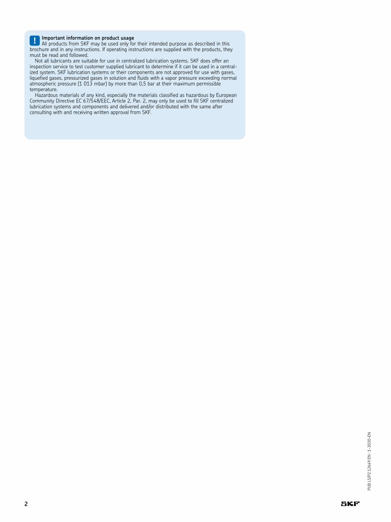
The KFG pump unit is an electrically
driven piston pump. Its core is comprised of a drive shaft with an
eccentric that drives up to three pump elements. Various designs
make it possible to accommodate this sturdy and proven principle
of operation to different circumstances.
The pump is comprised of four main components: Housing with
pump elements, reservoir with fill level monitoring, internal control
units and attachments. The housing integrates the motor, the drive
shaft with an eccentric and up to three pump elements for delivering
the lubricant. Positively driven pump elements should be used in
order to maintain the delivery rate in areas with extremely low
temperatures.
The reservoir is used for storage of the lubricant. It is available in
eight sizes and two variants for stationary utilization or with grease
follower plate technology for utilization in any position. The internal
control units monitor the switching on and off of the pump. In addi-
tion, they enable the evaluation of piston detector, pressure switch
and fill level signals. A variety of attachments permit the filling of the
reservoir, protect the pump (pressure limitation valve), relieve the
system (only when used in single-line systems) or enable the un-
complicated connection of the pump to the centralized lubrication
system.
Fields of application
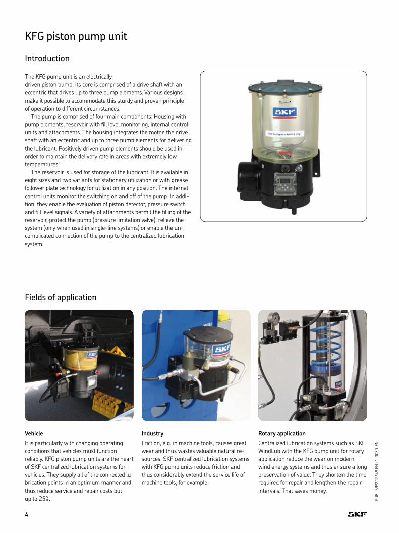
Vehicle
It is particularly with changing operating
conditions that vehicles must function
reliably. KFG piston pump units are the heart
of SKF centralized lubrication systems for
vehicles. They supply all of the connected lu-
brication points in an optimum manner and
thus reduce service and repair costs but
up to 25%.
Industry
Friction, e.g. in machine tools, causes great
wear and thus wastes valuable natural re-
sources. SKF centralized lubrication systems
with KFG pump units reduce friction and
thus considerably extend the service life of
machine tools, for example.
Rotary application
Centralized lubrication systems such as SKF
WindLub with the KFG pump unit for rotary
application reduce the wear on modern
wind energy systems and thus ensure a long
preservation of value. They shorten the time
required for repair and lengthen the repair
intervals. That saves money.
4
PU
B L
S/P
2 1
2649 E
N · 1
-3030-EN
KFG piston pump unit
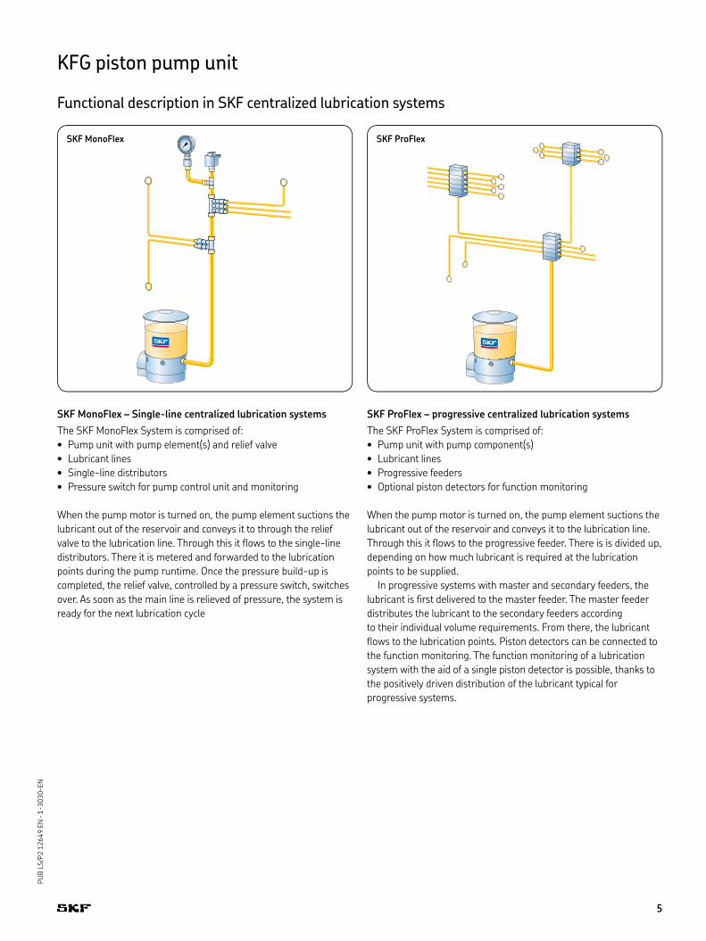
Functional description in SKF centralized lubrication systems
SKF MonoFlex – Single-line centralized lubrication systems
The SKF MonoFlex System is comprised of:
Pump unit with pump element(s) and relief valve •
Lubricant lines •
Single-line distributors •
Pressure switch for pump control unit and monitoring •
When the pump motor is turned on, the pump element suctions the
lubricant out of the reservoir and conveys it to through the relief
valve to the lubrication line. Through this it flows to the single-line
distributors. There it is metered and forwarded to the lubrication
points during the pump runtime. Once the pressure build-up is
completed, the relief valve, controlled by a pressure switch, switches
over. As soon as the main line is relieved of pressure, the system is
ready for the next lubrication cycle
SKF ProFlex – progressive centralized lubrication systems
The SKF ProFlex System is comprised of:
Pump unit with pump component(s)•
Lubricant lines•
Progressive feeders•
Optional piston detectors for function monitoring •
When the pump motor is turned on, the pump element suctions the
lubricant out of the reservoir and conveys it to the lubrication line.
Through this it flows to the progressive feeder. There is is divided up,
depending on how much lubricant is required at the lubrication
points to be supplied.
In progressive systems with master and secondary feeders, the
lubricant is first delivered to the master feeder. The master feeder
distributes the lubricant to the secondary feeders according
to their individual volume requirements. From there, the lubricant
flows to the lubrication points. Piston detectors can be connected to
the function monitoring. The function monitoring of a lubrication
system with the aid of a single piston detector is possible, thanks to
the positively driven distribution of the lubricant typical for
progressive systems.
SKF MonoFlex SKF ProFlex
5

PU
B L
S/P
2 1
2649 E
N · 1
-3030-EN
KFG piston pump unit
Main components
Pump housing
The housing of the KFG pump unit is made
of sturdy aluminum. Integrated within are
the electric motor, the power supply unit
(only with 230 V AC variant), the drive shaft
with eccentric and one to three pump ele-
ments. The eccentric converts the rotational
movement into a stroke movement of the
pump element. The pump element pushes
out lubricant during its forward movement
and suctions in new lubricant from the lu-
bricant reservoir during its retraction
movement.
In the design for the vehicle and industry
sector, the lubricant reservoir is filled
through a conical head nipple on the pump
housing. In addition, two different control
units (IG502-2-I and LC502) can be inte-
grated as optional equipment. Their displays
are attached in a readily accessible manner
to the front side of the pump housing. Basi-
cally speaking, the pump unit is available
with three voltage keys: 12 V DC, 24 V DC
and 230 V AC. KFG pump units with control
unit, a 230 V power supply unit or with me-
chanical fill level switch have a deep bottom
(foot). The overall dimensions are changed
as a result.
Pump elements
Pump elements deliver the lubricant to the
lubrication points or distributors through
lubrication lines. Five pump elements for
delivery rates of from 0.8 to 5.0 cm³/min
are available for selection in two designs:
with spring-return piston •
with positively driven piston •
In many application instances, the pump
element with spring-return piston is the
correct choice. The pump element with posi-
tively driven piston was developed for use in
extremely cold environments (to -30 °C).
or for high-viscosity lubricants. Up to three
pump elements can be installed in the KFG
pump unit. The possible attachment posi-
tions are located on the left (1), at the front
(2) and on the right (3) on the pump hous-
ing. The lubricant outlet on the pump ele-
ment has an M14x1.5 female thread for
connecting lubrication lines or valves. If no
pump element is installed, then the outlet of
the pump housing is sealed with a screw.
Marking of the pump elements
Model Spring-return
Positively driven
Delivery rate* [cm³ / min]
Number of the marking grooves on the head of the pump element Labeling
0,8 4 –1,3 3 J-31,8 2 H-22,5 1 G-15,0 0 L-0
! Note
If more than one pump element is
installed in a KFG pump unit for an SKF
MonoFlex system, then their outlets will
be consolidated externally to form one
main lubrication line. The total delivery
rate is then derived from the sum of the
respective delivery rates of the individual
pump elements.
The specified quantities refer to grease of * NLGI class 2 at 20 °C and a back pressure of 50 bar.
6

PU
B L
S/P
2 1
2649 E
N · 1
-3030-EN
KFG piston pump unit
Main components
Fill level monitoring through
capacitive proximity switches
Capacitive proximity switches are
contact-free sensors that react with an
electrical switching signal when a
medium approaches.
They are used in KFG pump units for mini-
mum fill level monitoring of the lubricating
medium fluid grease and grease of
NLGI class 1.
Fill level monitoring through
mechanical fill level switches
The mechanical fill level switches are
mounted on the agitator. The grease resis-
tance causes them to pivot downwards
when the reservoir is filled and the agitators
rotate. When the minimum fill level is
reached, the grease resistance lessens
against the rocker switch.
It pivots back and thus interrupts the contact
to the solenoid switch. The mechanical fill
level switches are used only in stationary
KFG units for fill level monitoring of the
lubricating medium of NLGI class 2 grease.
A version with signal smoothing is also
available for the evaluation of the signal with
external control units.
Fill level monitoring using cylinder
switches
In the case of cylinder switches, contact-
less solenoid switches are used. They mea-
sure the change of the magnetic field and
convert this into a digital signal. In the case
of the KFG pump, they are used solely in
units that have a grease follower plate.
When several cylinder switches are used
various switching points such as Minimum,
Maximum of Fill level pre-warnings can be
monitored by the detection of the position
of the grease follower plate.
Reservoir
Two different reservoir types exist for the
KFG pump unit: one for stationary and one
for rotary application. A grease follower plate
system patented by SVK is to be found in the
lubricant reservoir of the units for rotary
application. A spiral spring assembly is at-
tached to the grease follower plate. This
presses the follower plate onto the lubricant.
As a result, the lubricant is always available
at the pump element, independent of the
position of the unit. The filling of this reser-
voir variant is carried out through a quick-
action coupling on the reservoir cover in ac-
cordance with the "First In - First Out"
principle. This avoids having old grease in
the lubricant reservoir. In the reservoirs
without grease follower plate technology, for
industry and vehicle applications, the lubri-
cant is worked by an agitator. This avoids air
pockets and improves pumpability.
The filling of the variants without grease fol-
lower plate technology takes place through
the housing, as is described on page 6. Res-
ervoir capacities of from 2 to 20 kg are
available for vehicles and industrial plants
and reservoir capacities of from 4 to 15 kg
for rotary applications.
Depending on the field of application,
three variants exist for monitoring the fill
level in the lubricant reservoir: capacitive
proximity switches, mechanical fill level
switches and cylinder switches.
Cylinder switches are suitable for the
reservoir model with grease follower plate.
The capacitive proximity switch is suitable
for stationary application with grease and
fluid grease of the NLGI classes 1, 0, 00, and
000. The mechanical fill level switch is to
be used for the stationary application with
grease of NLGI class 2.
7
PU
B L
S/P
2 1
2649 E
N · 1
-3030-EN
KFG piston pump unit
Main components
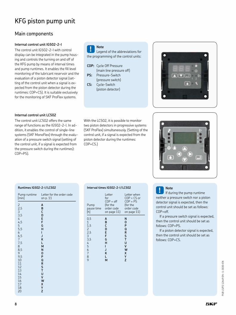
Internal control unit LC502
The control unit LC502 offers the same
range of functions as the IG502-2-I. In ad-
dition, it enables the control of single-line
systems (SKF MonoFlex) through the evalu-
ation of a pressure switch signal (setting of
the control unit, if a signal is expected from
the pressure switch during the runtimes):
COP=PS).
With the LC502, it is possible to monitor
two piston detectors in progressive systems
(SKF ProFlex) simultaneously. (Setting of the
control unit, if a signal is expected from the
piston detector during the runtimes:
COP=CS.)
Internal control unit IG502-2-I
The control unit IG502-2-I with control
display can be integrated in the pump hous-
ing and controls the turning on and off of
the KFG pump by means of interval times
and pump runtimes. It enables the fill level
monitoring of the lubricant reservoir and the
evaluation of a piston detector signal (set-
ting of the control unit when a signal is ex-
pected from the piston detector during the
runtimes: COP=CS). It is suitable exclusively
for the monitoring of SKF ProFlex systems.
Runtimes IG502-2-I / LC502
Pump runtime [min]
Letter for the order code on p. 11
2 A2,5 B3 C3,5 D4 E4,5 F5 G5,5 H6 I6,5 J7 K7,5 L8 M8,5 N9 O9,5 P10 Q11 R12 S13 T14 U15 V16 W17 X18 Y20 Z
! Note
If during the pump runtime
neither a pressure switch nor a piston
detector signal is expected, then the
control unit should be set as follows:
COP=off.
If a pressure switch signal is expected,
then the control unit should be set as
follows: COP=PS.
If a piston detector signal is expected,
then the control unit should be set as
follows: COP=CS.
Interval times IG502-2-I / LC502
Pumppause time [h]
Letter forCOP = off(for the order code on page 11)
Letter whenCOP = CS or COP = PS(for the order code on page 11)
0,5 A N1 B O1,5 C P2 D Q2,5 E R3 F S3,5 G T4 H U5 I V6 J W7 K X8 L Y9 M Z
! Note
Legend of the abbreviations for
the programming of the control units:
COP: Cycle Off Pressure
(main line pressure off)
PS: Pressure-Switch
(pressure switch)
CS: Cycle-Switch
(piston detector)
8

PU
B L
S/P
2 1
2649 E
N · 1
-3030-EN
KFG piston pump unit
Main components
Pressure regulating valve
In order to prevent an excessive operating pressure in the system,
a pivoted pressure regulating valve should be attached. If the oper-
ating pressure exceeds the cracking pressure of the pressure regu-
lating valve, then the valve will open and the lubricant can escape.
The pressure regulating valve is used primarily in progressive sys-
tems. One can select among variants with SKF plug connectors,
straight connector and with G 1/4" female thread.
Pressure relief valve with integrated pressure regulating valve
The valve offers both a pressure regulating and a pressure relief
function. SKF MonoFlex systems require pressure relief for the sys-
tem in order to conclude the metering of the distributors and thus to
enable a new lubrication cycle. The pressure regulating function
protects the system against excessive operating pressure. This valve
is therefore used exclusively in single-line systems. One can select
among variants with SKF plug connectors, straight connector and
adapter for G 1/4" female thread.
Fittings
A variety of different fittings
with the male thread M14×1.5 are available for selection for the
connection of the pump element to the lubrication lines of the cen-
tralized lubrication system. One can select among cross sections 6,
8, 10 and 12 mm in size.
If a G 1/4" connection is required, then a special adapter must be
used. Additional information regarding fittings and accessories are to
be found in the leaflet 1-0103-EN.
Socket for filling cylinder
For industry and vehicle applications, one of the three lubricant
outlets of the pump can, as an option, be equipped with one suitable
filler socket instead of with one pump element, in order to fill the
unit using a filling cylinder (cartridge).
Straight connector
Adapter
9

PU
B L
S/P
2 1
2649 E
N · 1
-3030-EN
Pressure regulating valvefor progressive systems(SKF ProFlex)
FittingSKF plugconnector
KFG piston pump unit
Designs
Order example
KFGL3R14XXBXEB+924KFG piston pump unit• LC 502 Control Unit• Reservoir capacity 6 kg• rotary application• Pump element with spring-return pistons• fill level indicator minimum• 1.8 cm³ / min delivery rate of the pump • element at outlet 3without fitting• Factory setting of the control unit• System voltage 24 V DC•
KFG with grease follower plate technology for rotary application (e.g. wind energy systems)
KFG unit for Industry / Vehicle applications
FittingCutting-sleeve screw union with sealing ring
! Note
This page shows possible designs
of the KFG units.
Not all components can be combined
with one another. The configurator on
the following page allows the functional
specification of a KFG reservoir pump
unit.
Pump element(spring-return)
Pump element(positively driven)
Control unit IG502-2-I
LC 502 Control Unit
Fill level monitoring (capacitive proximity switch for fluid grease, NLGI classes 1, 0, 00, 000)
Pressure relief valve with integrated pressure regulating valve for single-line systems(SKF MonoFlex)
Fill level monitoring(cylinder switch for rotary application)
Fill level monitoring(mechan. switch for grease, NLGI class 2)
10
PU
B L
S/P
2 1
2649 E
N · 1
-3030-EN
KFG piston pump unit
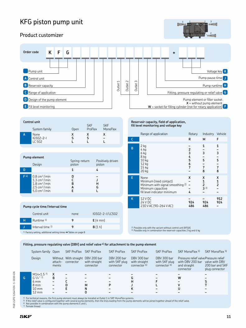
Product customizer
Order code K F G +
O
utlet 1
Pump unit
O
utlet 2
O
utlet 3
Voltage key K
A Control unit Pump pause time J
B Reservoir capacity Pump runtime H
C Range of application Fitting, pressure regulating or relief valve G
D Design of the pump element Pump element or filler socket X = without pump element
W = socket for filling cylinder (not for rotary application)E Fill level monitoring F
Fitting, pressure regulating valve (DBV) and relief valve 4) for attachment to the pump element
System family Open SKF ProFlex SKF ProFlex SKF ProFlex SKF ProFlex SKF ProFlex SKF MonoFlex 5) SKF MonoFlex 5)
Design Without attach-ments
With straight connector
DBV 200 bar with straight connector
DBV 200 barwith SKF plugconnector
DBV 300 barwith straight connector 6)
DBV 300 barwith SKF plugconnector 6)
Pressure relief valvewith DBV 200 bar and straight connector
Pressure relief valve with DBV 200 bar and SKF plug connector
M14×1.5 7) X – – – – – – –G G 1/4 " 7) B – – – G – W –
6 mm – C – – H F – S8 mm – D M P J L V T10 mm – E N – K – U –12 mm – – O – – – – –
4) For technical reasons, the first pump element must always be installed at Outlet 1 in SKF MonoFlex systems. 5) If the relief valve is configured together with several pump elements, then the lines leading from the pump elements will be joined together ahead of the relief valve.6) Not possible in combination with the pump elements E and L7) Female thread
Pump element
DesignSpring-return piston
Positively driven piston
D 1 4
F 4) 0.8 cm³ / min D –1.3 cm³ / min C J1.8 cm³ / min B H2.5 cm³ / min A G5.0 cm³ / min E L
Reservoir capacity, field of application, fill level monitoring and voltage key
Range of application Rotary Industry Vehicle
C R M F
B2 kg – 1 14 kg 2 – –6 kg 3 3 38 kg 4 – –10 kg 5 5 512 kg 6 – –15 kg 7 7 720 kg – 8 8
E None X X XMinimum (reed contact) – 1 1Minimum with signal smoothing 2) – 2 2Minimum capacitive – 3 3) –fill level indicator minimum 4 – –
K 12 V DC – – 91224 V DC 924 924 924230 V AC (90–264 V AC ) 486 486 –
2) Possible only with the variant without control unit (KFGX)3) Possible only in combination the reservoir capacities 2 kg and 6 kg
Control unit
System family OpenSKF ProFlex
SKF MonoFlex
A None X X XIG502-2-I S S –LC 502 L L L
Pump cycle time / Interval time
Control unit none IG502-2-I / LC502
H Runtime 1) 9 E (4 min)
J Interval time 1) 9 B (1 h)
1) Factory setting, additional setting times ➔ Tables on page 8
11

PU
B L
S/P
2 1
2649 E
N · 1
-3030-EN
KFG piston pump unit
Dimensioned drawings
KFG unit without deep bottom (for vehicle and industrial applications)
KFG unit with deep bottom (for vehicle and industrial applications)
Design with deep bottom, if:Fill level monitoring Model 1 or 2–or voltage key 486–or control unit Model S or L–
(2 k
g r
es.
)
(6 k
g r
ese
rvoir
)
(10 k
g r
ese
rvoir
)
(10 k
g r
ese
rvoir
)
(20 k
g r
ese
rvoir
)
(20 k
g r
ese
rvoir
)(2
0 k
g r
ese
rvoir
)
(15 k
g r
ese
rvoir
)(1
5 k
g r
ese
rvoir
)
(15 k
g r
ese
rvoir
)
(2 k
g r
es.
)
(6 k
g r
ese
rvoir
)
(10 k
g r
ese
rvoir
)
(10 k
g r
ese
rvoir
)
(20 k
g r
ese
rvoir
)
(20 k
g r
ese
rvoir
)(2
0 k
g r
ese
rvoir
)
(15 k
g r
ese
rvoir
)(1
5 k
g r
ese
rvoir
)
(15 k
g r
ese
rvoir
)
! Important note
Starting with a reservoir filling capacity of 10 kg, the only
fastening permitted is with the retaining ring on the reservoir.
12

PU
B L
S/P
2 1
2649 E
N · 1
-3030-EN
KFG piston pump unit
Dimensioned drawings
KFG unit without deep bottom (for rotary application)
KFG unit with deep bottom (for rotary application)
Design with deep bottom, if:voltage key 486–or control unit Model S or L–
(6 k
g r
ese
rvoir
)
(4 k
g r
ese
rvoir
) (10 k
g r
ese
rvoir
)
(10 k
g r
ese
rvoir
)
(8 k
g r
ese
rvoir
)
(8 k
g r
ese
rvoir
)
(15 k
g r
ese
rvoir
)
(15 k
g r
ese
rvoir
)(1
5 k
g r
ese
rvoir
)
(12 k
g r
ese
rvoir
)(1
2 k
g r
ese
rvoir
)
(12 k
g r
ese
rvoir
)
(6 k
g r
ese
rvoir
)
(4 k
g r
ese
rvoir
)
(10 k
g r
ese
rvoir
)
(10 k
g r
ese
rvoir
)
(8 k
g r
ese
rvoir
)
(8 k
g r
ese
rvoir
)
(15 k
g r
ese
rvoir
)
(15 k
g r
ese
rvoir
)(1
5 k
g r
ese
rvoir
)
(12 k
g r
ese
rvoir
)(1
2 k
g r
ese
rvoir
)
(12 k
g r
ese
rvoir
)
! Important note
Starting with a reservoir filling capacity of 10 kg, the only
fastening permitted is with the retaining ring on the reservoir.
13
PU
B L
S/P
2 1
2649 E
N · 1
-3030-EN
KFG piston pump unit
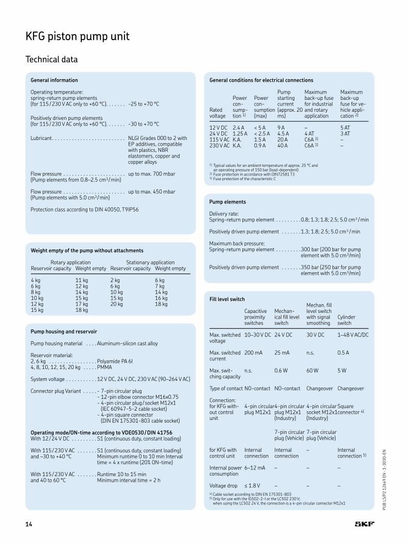
Technical data
Weight empty of the pump without attachments
Rotary application Stationary applicationReservoir capacity Weight empty Reservoir capacity Weight empty
4 kg 11 kg 2 kg 6 kg6 kg 12 kg 6 kg 7 kg8 kg 14 kg 10 kg 14 kg10 kg 15 kg 15 kg 16 kg12 kg 17 kg 20 kg 18 kg15 kg 18 kg
General conditions for electrical connections
Ratedvoltage
Power con-sump-tion 1)
Power con-sumption (max)
Pump startingcurrent (approx. 20 ms)
Maximum back-up fuse for industrial and rotary application
Maximum back-up fuse for ve-hicle appli-cation 2)
12 V DC 2.4 A < 5 A 9 A – 5 AT24 V DC 1.25 A < 2.5 A 4.5 A 4 AT 3 AT 115 V AC K.A. 1.5 A 20 A C6A 3) –230 V AC K.A. 0.9 A 40 A C6A 3) –
1) Typical values for an ambient temperature of approx. 25 °C and an operating pressure of 150 bar (load-dependent)2) Fuse protection in accordance with DIN72581 T33) Fuse protection of the characteristic C
General information
Operating temperature:spring-return pump elements (for 115 / 230 V AC only to +60 °C). . . . . . . -25 to +70 °C
Positively driven pump elements (for 115 / 230 V AC only to +60 °C). . . . . . . -30 to +70 °C
Lubricant. . . . . . . . . . . . . . . . . . . . . . . . . . NLGI Grades 000 to 2 with EP additives, compatible with plastics, NBR elastomers, copper and copper alloys
Flow pressure . . . . . . . . . . . . . . . . . . . . . . up to max. 700 mbar(Pump elements from 0.8–2.5 cm3 / min)
Flow pressure . . . . . . . . . . . . . . . . . . . . . . up to max. 450 mbar(Pump elements with 5.0 cm3 / min)
Protection class according to DIN 40050, T9 IP56
Pump housing and reservoir
Pump housing material . . . . Aluminum-silicon cast alloy
Reservoir material: 2, 6 kg . . . . . . . . . . . . . . . . . Polyamide PA 6I4, 8, 10, 12, 15, 20 kg . . . . . PMMA
System voltage . . . . . . . . . . . 12 V DC, 24 V DC, 230 V AC (90–264 V AC)
Connector plug Variant . . . . . - 7-pin circular plug- 12-pin elbow connector M16x0.75- 4-pin circular plug / socket M12x1 (IEC 60947-5-2 cable socket)- 4-pin square connector (DIN EN 175301-803 cable socket)
Operating mode/ON-time according to VDE0530 / DIN 41756With 12 / 24 V DC . . . . . . . . .
With 115 / 230 V AC . . . . . . .and –30 to +40 °C
With 115 / 230 V AC . . . . . . .and 40 to 60 °C
S1 (continuous duty, constant loading)
S1 (continuous duty, constant loading)Minimum runtime 0 to 10 min Interval time = 4 x runtime (20% ON-time)
Runtime 10 to 15 min Minimum interval time = 2 h
Pump elements
Delivery rate:Spring-return pump element . . . . . . . . . 0.8; 1.3; 1.8; 2.5; 5.0 cm³ / min
Positively driven pump element . . . . . . .1.3; 1.8; 2.5; 5.0 cm³ / min
Maximum back pressure:Spring-return pump element . . . . . . . . .300 bar (200 bar for pump
element with 5.0 cm³/min)
Positively driven pump element . . . . . . .350 bar (250 bar for pump element with 5.0 cm³/min)
Fill level switch
Capacitive proximity switches
Mechan-ical fill level switch
Mechan. fill level switch with signal smoothing
Cylinderswitch
Max. switched voltage
10–30 V DC 24 V DC 30 V DC 1–48 V AC/DC
Max. switched current
200 mA 25 mA n.s. 0.5 A
Max. swit-ching capacity
n.s. 0.6 W 60 W 5 W
Type of contact NO-contact NO-contact Changeover Changeover
Connection:for KFG with-out control unit
4-pin circular plug M12x1
4-pin circular plug M12x1 (Industry)
4-pin circular socket M12x1 (Industry)
Square connector 4)
7-pin circular plug (Vehicle)
7-pin circular plug (Vehicle)
for KFG with control unit
Internal connection
Internal connection
– Internal connection 5)
Internal power consumption
6–12 mA – – –
Voltage drop ≤ 1.8 V – – –
4) Cable socket according to DIN EN 175301-803 5) Only for use with the IG502-2-I or the LC502 230 V;
when using the LC502 24 V, the connection is a 4-pin circular connector M12x1
14

PU
B L
S/P
2 1
2649 E
N · 1
-3030-EN
KFG piston pump unit
Accessories
Filler coupling
As an alternative to a conical head nipple,
the unit can also be equipped with a filler
socket in order to fill it with a filling pump,
e.g. the manual drum pump. A correspond-
ing coupling socket and a hose socket must
be mounted on the filling pump.
Filling coupling Part A
Description Order number
Filler socket 24-9909-0244with sealing ring
Manual drum pump
The manual drum pump is for simple filling-
up of the KFG piston pump unit. It is avail-
able in the designs with and without trolley
and is suitable for NLGI class 1 and 2 greas-
es. The delivery rate of the drum pump is
approx. 40 cm³/stroke.
Filling cylinder
Description Order number
Filling cylinder 169-000-171
Drum pump
Description Order number
Drum pump withrunning gear:For 25 kg drum 169-000-042For 50 kg drum 169-000-054
Drum pump withoutrunning gear:For 25 kg drum 169-000-342
Filling cylinder
For industry and vehicle applications, a fill-
ing cylinder can also be optionally used to fill
the pump unit through one of the lubricant
outlets. To accomplish this, a filler socket
must be configured in the order code in
place of a lubricant outlet.
Coupling socket
Hose socket
Filler socket
Filler coupling Part C
Description Order number
Hose socket:ø13 mm 857-760-007ø16 mm 857-870-002
Filler coupling Part B
Description Order number
Coupling socket 995-001-500
15

PU
B L
S/P
2 1
2649 E
N · 1
-3030-EN
Pressure gauge
Reed pen pressure gauges with glycerin
filling are available for visual documentation
of the pressures in the SKF centralized
lubrication system. The parts which come
into contact with the medium are made of
copper alloys. These pressure gauges are
suitable for highly dynamic pressure loads
and vibrations. The necessary accessory
parts for fastening are to be found in the
leaflet 1-0103-EN.
Pressure gauge
Description Order number
Pressure gauge, complete:0 to 250 bar 169-125-000.U10 to 400 bar 169-140-001.U1
Pressure gauge screw union: for ø 6 mm tubing 441-106-162for ø 8 mm tubing 441-108-162for ø 10 mm tubing 441-110-163for ø 12 mm tubing 441-112-162
IG502-2-E external control unit
The IG502-2-E is an external control unit
with a control display. It controls the turning
on and off of the KFG pump by means of in-
terval and pump runtimes. Furthermore, it
enables the fill level monitoring of the lubri-
cant reservoir and the evaluation on one
piston detector signal. In addition, one can
operate the pump unit with it, even from a
short distance, e.g. from the cab of a vehicle.
It is suitable only for SKF ProFlex systems.
KFG piston pump unit
Accessories
Retaining ring and drilling template
For all KFG units with reservoir capacities
up to and including 6 kg, a special drilling
template exists as an installation aid made
of self-adhesive foil. In addition to that, a
stabilizing retaining angle is also available
for vertical installation.
Electrical accessories
The T plug is suitable when additional
connectors are required, e.g. for a separate
indicator lamp.
External control unit
Description Order number
External control unit
IG502-2-E(Always please include specification of the control voltage 12 V or 24 V)
Retaining ring and drilling template
Description Order number
Self-adhesive drilling template 951-130-115
Pump retaining plate 881-290-430
Electrical accessories
Description Order number
T-plug M12×1 with two outgoing cables (socket M12×1)
179-990-700
16
PU
B L
S/P
2 1
2649 E
N · 1
-3030-EN
KFG piston pump unit
Special designs
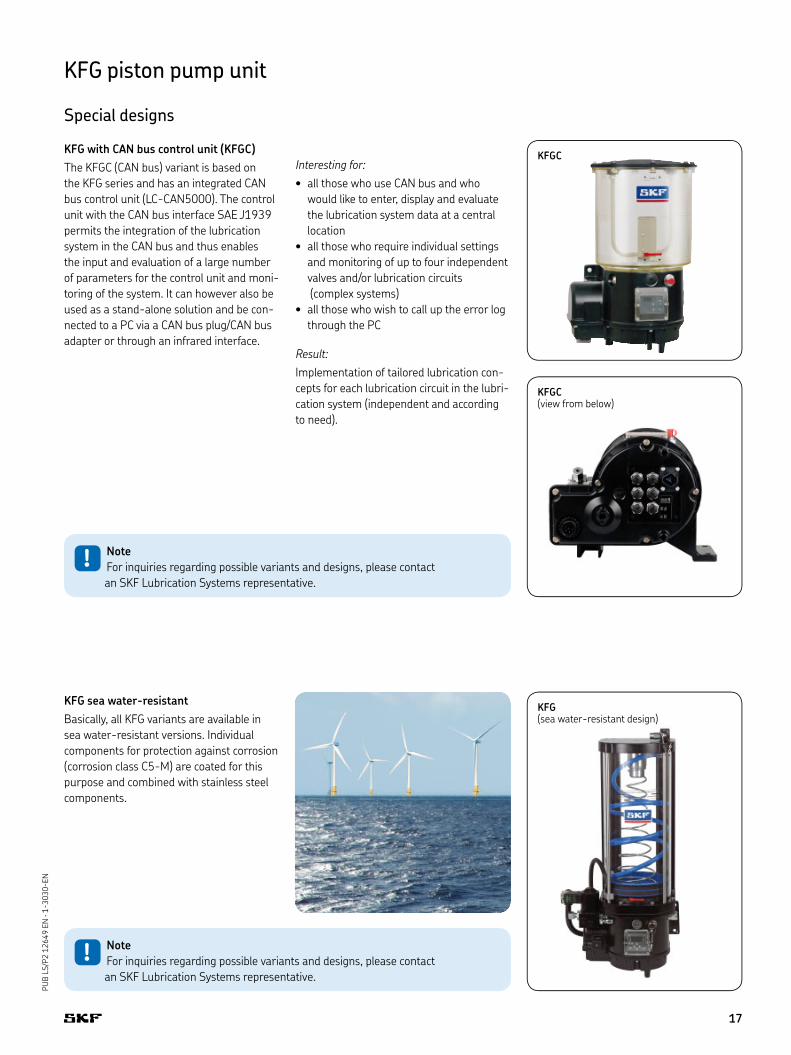
KFG with CAN bus control unit (KFGC)
The KFGC (CAN bus) variant is based on
the KFG series and has an integrated CAN
bus control unit (LC-CAN5000). The control
unit with the CAN bus interface SAE J1939
permits the integration of the lubrication
system in the CAN bus and thus enables
the input and evaluation of a large number
of parameters for the control unit and moni-
toring of the system. It can however also be
used as a stand-alone solution and be con-
nected to a PC via a CAN bus plug/CAN bus
adapter or through an infrared interface.
Interesting for:all those who use CAN bus and who •
would like to enter, display and evaluate
the lubrication system data at a central
location
all those who require individual settings •
and monitoring of up to four independent
valves and/or lubrication circuits
(complex systems)
all those who wish to call up the error log •
through the PC
Result:Implementation of tailored lubrication con-
cepts for each lubrication circuit in the lubri-
cation system (independent and according
to need).
KFG sea water-resistant
Basically, all KFG variants are available in
sea water-resistant versions. Individual
components for protection against corrosion
(corrosion class C5-M) are coated for this
purpose and combined with stainless steel
components.
KFGC
KFGC (view from below)
KFG(sea water-resistant design)
! Note
For inquiries regarding possible variants and designs, please contact
an SKF Lubrication Systems representative.
! Note
For inquiries regarding possible variants and designs, please contact
an SKF Lubrication Systems representative.
17
PU
B L
S/P
2 1
2649 E
N · 1
-3030-EN
12–14 45
53
1–9
15–24
50
1–9
49
47
42
48! Only original spare parts from
SKF Lubrication Systems
Germany AG may be used.
Unauthorized alterations to products
and the use of non-original spare parts
and accessories are not permitted.
! Dismantling of the product or
individual parts thereof within the
statutory warranty period is not permit-
ted and voids any claims.
! Repair work may only be per-
formed by the Service depart-
ment of SKF Lubrication Systems Ger-
many AG. In the event of questions in
reference to installation or maintenance,
please contact SKF Lubrication Systems
Germany AG or a an SKF-authorized
dealer or service partner.
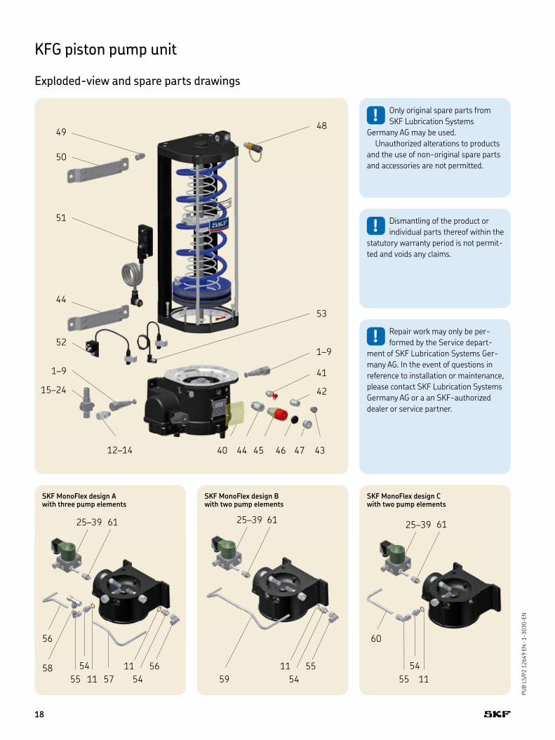
KFG piston pump unit
Exploded-view and spare parts drawings
51
44
52
41
4340 4644
SKF MonoFlex design A with three pump elements
SKF MonoFlex design B with two pump elements
SKF MonoFlex design C with two pump elements
25–39 25–3925–3961 61
61
59
5611
54
56
57
58
55
54
60
55
54
11
5511
5411
18

PU
B L
S/P
2 1
2649 E
N · 1
-3030-EN
KFG piston pump unit
Wearing parts and spare parts
1) DBV=pressure regulating valve
Wearing parts
Item Order number Letter Description
1 KFG1.U0 E Pump element with spring-return piston 5.0 cm³/min2 KFG1.U1 A Pump element with spring-return piston 2.5 cm³/min3 KFG1.U2 B Pump element with spring-return piston 1.8 cm³/min4 KFG1.U3 C Pump element with spring-return piston 1.3 cm³/min5 KFG1.U4 D Pump element with spring-return piston 0.8 cm³/min6 KFG1.U0-E L Pump element with positively driven piston 5.0 cm³/min7 KFG1.U1-E G Pump element with positively driven piston 2.5 cm³/min8 KFG1.U2-E H Pump element with positively driven piston 1.8 cm³/min9 KFG1.U3-E J Pump element with positively driven piston 1.3 cm³/min
Spare parts
Item Order number Letter Description
10 301-034 B Adapter M14x1.5 on G1/4 (sealing ring Item 11 must be ordered separately)11 DIN7603-A14X18-AL – Sealing ring12 406-413 C Straight connector for tube ø 6 mm13 408-413 D Straight connector for tube ø 8 mm14 410-403 E Straight connector for tube ø 10 mm15 161-210-063 M DBV 1) 200 bar, straight connector ø 8 mm16 161-210-065 N DBV 1) 200 bar, straight connector ø 10 mm17 161-210-062 O DBV 1) 200 bar, straight connector ø 12 mm18 161-210-061 P DBV 1) 200 bar, SKF plug connector ø 8 mm19 161-210-036 G DBV 1) 300 bar, female thread G1/420 161-210-012 H DBV 1) 300 bar, straight connector ø 6 mm21 161-210-024 J DBV 1) 300 bar, straight connector ø 8 mm22 161-210-066 K DBV 1) 300 bar, straight connector ø 10 mm23 161-210-021 F DBV 1) 300 bar, SKF plug connector ø 6 mm24 161-210-034 L DBV 1) 300 bar, SKF plug connector ø 8 mm25 24-1254-2634 W Relief valve with DBV 1) 200 bar, female thread G1/4, 12 V design26 24-1254-2635 W Relief valve with DBV 1) 200 bar, female thread G1/4, 24 V design27 24-1254-2636 W Relief valve with DBV 1) 200 bar, female thread G1/4, 230 V design28 24-1254-2640 V Relief valve with DBV 1) 200 bar, straight connector ø 8 mm, 12 V design29 24-1254-2641 V Relief valve with DBV 1) 200 bar, straight connector ø 8 mm, 24 V design30 24-1254-2642 V Relief valve with DBV 1) 200 bar, straight connector ø 8 mm, 230 V design31 24-1254-2637 U Relief valve with DBV 1) 200 bar, straight connector ø 10 mm, 12 V design32 24-1254-2638 U Relief valve with DBV 1) 200 bar, straight connector ø 10 mm, 24 V design33 24-1254-2639 U Relief valve with DBV 1) 200 bar, straight connector ø 10 mm, 230 V design34 24-1254-2643 S Relief valve with DBV 1) 200 bar, SKF plug connector ø 6 mm, 12 V design35 24-1254-2644 S Relief valve with DBV 1) 200 bar, SKF plug connector ø 6 mm, 24 V design36 24-1254-2645 S Relief valve with DBV 1) 200 bar, SKF plug connector ø 6 mm, 230 V design37 24-1254-2646 T Relief valve with DBV 1) 200 bar, SKF plug connector ø 8 mm, 12 V design38 24-1254-2647 T Relief valve with DBV 1) 200 bar, SKF plug connector ø 8 mm, 24 V design39 24-1254-2648 T Relief valve with DBV 1) 200 bar, SKF plug connector ø 8 mm, 230 V design40 KFGS1.54 – Transparent cover for the control unit41 24-9909-0241 – KFG filling nipple G1/4 kit42 24-9909-0248 – KFG DBV 1) in the housing 1.5 bar G1/4 kit (rotary application)43 24-9909-0242 – KFG screw plug G1/4 kit44 24-9909-0247 – KFG DBV in the housing 1.5 bar M20x1.5 kit (rotary application)45 169-000-174 – KFG filler socket M20x1.5 kit (Industry, Vehicle)46 KFG1.128 – Screw plug, plastic, with O-ring M20x1.5 (Industry, Vehicle)47 24-9909-0250 – KFG screw plug, steel M20x1.5 kit (rotary application)48 24-9909-0244 – KFG filler coupling G1/4 kit49 24-9909-0249 – KFG DBV 1) on the housing cover 30 bar G1/4 kit (rotary application)50 24-9909-0243 – KFG fastening kit (for reservoir capacities from 8 kg to 20 kg only)51 24-9909-0246 – KFG sensor / actuator box kit, 230 V (+486) Industry or rotary application52 24-9909-0251 – KFG fill level monitoring with square connector kit (rotary application)53 24-9909-0252 – KFG fill level monitoring with M12x1 plug (rotary application)54 408-313 – Threaded socket55 443-308-351 – Elbow connector56 44-1741-2953 – Pre-bent tubing57 44-1741-2954 – Pre-bent tubing58 445-808-351 – Union T59 44-1741-2956 – Pre-bent tubing60 44-1741-2955 – Pre-bent tubing61 24-9909-0245 – SKF MonoFlex return line G1/4 kit
19

Bearings and unitsSeals Lubrication
systems
Mechatronics Services
The Power of Knowledge Engineering
Drawing on five areas of competence and application-specific expertise amassed over more than 100
years, SKF brings innovative solutions to OEMs and production facilities in every major industry world-
wide. These five competence areas include bearings and units, seals, lubrication systems, mechatronics
(combining mechanics and electronics into intelligent systems), and a wide range of services, from 3-D
computer modelling to advanced condition monitoring and reliability and asset management systems.
A global presence provides SKF customers uniform quality standards and worldwide product availability.
This leaflet was presented to you by:
® SKF, SKF MonoFlex, SKF ProFlex and SKF WindLub are registered trademarks of the SKF Group.
© SKF Group 2012
The contents of this publication are the copyright of the publisher and may not be reproduced (even extracts) unless prior written
permission is granted. Every care has been taken to ensure the accuracy of the information contained in this publication but no liability
can be accepted for any loss or damage whether direct, indirect or consequential, arising out of use of the information contained herein.
PUB LS/P2 12649 EN · February 2012 · 1-3030-EN
This publication replaces publications 1-3034-EN and 1-3035-EN.
Further leaflets:
1-0103-EN Fittings and accessories1-9201-EN Feeding lubricants with centralized lubrication systems1-1701-EN Pressure switches, product series DSA, DSB, DSC, DSD1-3013-EN Modular feeder PSG2 (Progressive feeder)1-3014-EN Modular feeder PSG3 (Progressive feeder)1-3015-EN Sectional feeder VPK (Progressive feeder)1-3016-EN Sectional feeder VP (Progressive feeder)1-3017-EN Sectional feeder VPB (Progressive feeder)1-5001-EN Lubricant distributor SKF MonoFlex (single-line distributor)
SKF Lubrication Systems Germany AG
HockenheimPlant
2. Industriestrasse 4
68766 Hockenheim
Germany
Tel. +49 (0)6205 27-0
Fax +49 (0)6205 27-100
skf.com/lubrication
Related Documents