1 1 1 SAPPHIRE PURE ELEMENT II Electronic Emission Notices Electronic Emission Notices Electronic Emission Notices Electronic Emission Notices Electronic Emission Notices Federal Communications Commission (FCC) Statement Federal Communications Commission (FCC) Statement Federal Communications Commission (FCC) Statement Federal Communications Commission (FCC) Statement Federal Communications Commission (FCC) Statement This equipment has been tested and found to comply with the limits for a Class B digital device, pursuant to Part 15 of FCC Rules. These limits are designed to provide reasonable protection against harmful interference in a residential installation. This equipment generates, uses and can radiate radio frequency energy and, if not installed and used in accordance with instructions contained in this manual, may cause harmful interference to radio and t elevision communic ations. However, there is no guarantee that interference will not occur in a particular installation. If this equipment does cause harmful interference to radio or television reception, which can be determined by turning the equipment off and on, the user is encouraged to try to correct the interference by one or more of the following measures: - REORIENT OR RELOCATE THE RECEIVI NG A NTEN NA - INC REA SE THE SEP ARA TION BETWEEN THE E QUIP MEN T A ND THE REC EIV ER - CON NEC T T HE EQU IPM ENT INT O AN OUT LET ON A C IRC UIT DIF FER ENT FRO M THA T OF THE RECEIVER - CON SUL T T HE DEAL ER OR AN EXP ERIE NCED AUDI O/T ELEV ISIO N TECH NICI AN NOTE: Connecting this device to peripheral devices that do not comply with Class B requirements, or using an unshielded peripheral data cable, could also result in harmful interference to radio or television reception. The user is cautioned that any changes or modifications not expressly approved by the party responsible for compliance could void the user’s authority to operate this equipment. To ensure that the use of this product does not contribute to interference, it is necessary to use shielded I/O cables. Copyright Copyright Copyright Copyright Copyright This manual is copyrighted with all rights reserved. No portion of this manual may be copied or reproduced by any means. While every precaution has been taken in the preparation of this manual, no responsibility for errors or omissions is assumed. Neither is any liability assumed for damages resulting from the use of the information contained herein. Trademarks Trademarks Trademarks Trademarks Trademarks All brand names, logos and registered trademarks mentioned are property of their respective owners.

Welcome message from author
This document is posted to help you gain knowledge. Please leave a comment to let me know what you think about it! Share it to your friends and learn new things together.
Transcript

8/4/2019 126 Manual
http://slidepdf.com/reader/full/126-manual 1/40
11111
SAPPHIRE PURE ELEMENT II
Electronic Emission NoticesElectronic Emission NoticesElectronic Emission NoticesElectronic Emission NoticesElectronic Emission Notices
Federal Communications Commission (FCC) StatementFederal Communications Commission (FCC) StatementFederal Communications Commission (FCC) StatementFederal Communications Commission (FCC) StatementFederal Communications Commission (FCC) Statement
This equipment has been tested and found to comply with the limits for a Class B digital
device, pursuant to Part 15 of FCC Rules. These limits are designed to provide reasonable
protection against harmful interference in a residential installation. This equipment
generates, uses and can radiate radio frequency energy and, if not installed and used in
accordance with instructions contained in this manual, may cause harmful interference
to radio and television communications. However, there is no guarantee that interference
will not occur in a particular installation.
If this equipment does cause harmful interference to radio or television reception, which
can be determined by turning the equipment off and on, the user is encouraged to try to
correct the interference by one or more of the following measures:
- REORIENT OR RELOCATE THE RECEIVING ANTENNA
- INCREASE THE SEPARATION BETWEEN THE EQUIPMENT AND THE RECEIVER
- CONNECT THE EQUIPMENT INTO AN OUTLET ON A CIRCUIT DIFFERENT FROM
THAT OF THE RECEIVER
- CONSULT THE DEALER OR AN EXPERIENCED AUDIO/TELEVISION TECHNICIAN
NOTE: Connecting this device to peripheral devices that do not comply with Class B
requirements, or using an unshielded peripheral data cable, could also result in
harmful interference to radio or television reception.
The user is cautioned that any changes or modifications not expressly approved
by the party responsible for compliance could void the user’s authority to operate
this equipment.
To ensure that the use of this product does not contribute to interference, it is
necessary to use shielded I/O cables.
CopyrightCopyrightCopyrightCopyrightCopyright
This manual is copyrighted with all rights reserved. No portion of this manual may be
copied or reproduced by any means.
While every precaution has been taken in the preparation of this manual, no responsibility
for errors or omissions is assumed. Neither is any liability assumed for damages resulting
from the use of the information contained herein.
TrademarksTrademarksTrademarksTrademarksTrademarks
All brand names, logos and registered trademarks mentioned are property of their
respective owners.

8/4/2019 126 Manual
http://slidepdf.com/reader/full/126-manual 2/40
22222
PE-I7RC410M-2PE-I7RC410M-2PE-I7RC410M-2PE-I7RC410M-2PE-I7RC410M-2 User’s Manual
TTTTT ABLE OF CONTENTS ABLE OF CONTENTS ABLE OF CONTENTS ABLE OF CONTENTS ABLE OF CONTENTS
HARDWARE CONFIGURATIONHARDWARE CONFIGURATIONHARDWARE CONFIGURATIONHARDWARE CONFIGURATIONHARDWARE CONFIGURATION ................................................................................................................................................................................................................................................................................... 44444
Key Features ......................................................................................... 4
MOTHERBOARD LAYOUTMOTHERBOARD LAYOUTMOTHERBOARD LAYOUTMOTHERBOARD LAYOUTMOTHERBOARD LAYOUT ................................................................................................................................................................................................................................................................................................................................ 77777
REAR PREAR PREAR PREAR PREAR P ANEL ANEL ANEL ANEL ANEL .................................................................................................................................................................................................................................................................................................................................................................................................................................... 88888
AUDIO CONFIGURATION AUDIO CONFIGURATION AUDIO CONFIGURATION AUDIO CONFIGURATION AUDIO CONFIGURATION ................................................................................................................................................................................................................................................................................................................................ 1010101010
SPEAKER CONFIGURATIONSPEAKER CONFIGURATIONSPEAKER CONFIGURATIONSPEAKER CONFIGURATIONSPEAKER CONFIGURATION ............................................................................................................................................................................................................................................................................................................ 1010101010
Method 1: 4/6 Surround audio output on back panel only..................... 10
Method 2: Using S-Bracket connectors ................................................. 12
CONNECTORSCONNECTORSCONNECTORSCONNECTORSCONNECTORS ..................................................................................................................................................................................................................................................................................................................................................................................................................... 1414141414
Floppy Disk Drive Connector - CN3...................................................... 14
IDE Connectors - CN1, CN2.................................................................. 14
SPDIF Output Connector - J19................................................................ ..... 15
TV Out Header - J3 ................................................................................. 16
Chassis Alarm Lead - JP12 .................................................................. 17
Fan Power Headers - CPUFAN1, SYSFAN1................................. ............ 18Power LED - D55, D56................................. ............................................. 18
CD-IN Header - J18 ............................................................................... 19
AUX-IN Header - J20.............................................................................. 19
Front Panel Audio Header - FP-S1 ........................................................ 20
USB Headers - FP-U1, FP-U2 ............................................................... 21
Front Panel Header - FP1 ...................................................................... 21
Serial ATA Hard Disk Connectors - SATA1,SATA2 .................................. 22
JUMPER SETTING JUMPER SETTING JUMPER SETTING JUMPER SETTING JUMPER SETTING ...................................................................................................................................................................................................................................................................................................................................................................................................... 24
JP9-CMOS Clear .................................................................................... 24
JP2-Onboard AC97 Sound Select ......................................................... 24
JP13-Onboard LAN Select..................................................................... 24

8/4/2019 126 Manual
http://slidepdf.com/reader/full/126-manual 3/40
33333
SAPPHIRE PURE ELEMENT II
SLOTSSLOTSSLOTSSLOTSSLOTS ...................................................................................................................................................................................................................................................................................................................................................................................................................................................................................... 2525252525
CPU INSTCPU INSTCPU INSTCPU INSTCPU INST ALLA ALLA ALLA ALLA ALLA TIONTIONTIONTIONTION ....................................................................................................................................................................................................................................................................................................................................................................................... 2626262626
INSTALL DDRII DIMMINSTALL DDRII DIMMINSTALL DDRII DIMMINSTALL DDRII DIMMINSTALL DDRII DIMMsssss .................................................................................................................................................................................................................................................................................................................................................... 3030303030
BIOS SETUPBIOS SETUPBIOS SETUPBIOS SETUPBIOS SETUP ......................................................................................................................................................................................................................................................................................................................................................................................................................................... 3131313131
About the Setup Utility ............................................................................ 31
The Standard Configuration .................................................................. 31
Entering the Setup Utility........................................................................ 31
Main Menu .............................................................................................. 32
Standard CMOS Features ..................................................................... 33
Advanced BIOS Features ....................................................................... 34Advanced Chipset Features .................................................................. 34
Integrated Peripherals ........................................................................... 34
Power Management Setup .................................................................... 34
PnP/PCI Configurations ........................................................................ 34
PC Health Status ................................................................................... 34
Set Supervisor/User Password ............................................................. 35
Save & Exit Setup ................................................................................... 35
Exit Without Saving ................................................................................. 35BIOS Update Procedure ........................................................................ 36
SATA RAID SETUPSATA RAID SETUPSATA RAID SETUPSATA RAID SETUPSATA RAID SETUP .................................................................................................................................................................................................................................................................................................................................................................................. 3737373737
Creating RAID Sets ................................................................................ 37
Deleting RAID Sets ................................................................................ 38
Resolving Conflict .................................................................................. 38
DRIVER AND RAID SOFTW DRIVER AND RAID SOFTW DRIVER AND RAID SOFTW DRIVER AND RAID SOFTW DRIVER AND RAID SOFTW ARE INST ARE INST ARE INST ARE INST ARE INST ALLA ALLA ALLA ALLA ALLA TIONTIONTIONTIONTION ............................................................................................................................................................................... 3939393939
Microsoft Windows Driver Installation ................................................... 39
Install Windows2000/XP ........................................................................ 39
APPENDIX APPENDIX APPENDIX APPENDIX APPENDIX ................................................................................................................................................................................................................................................................................................................................................................................................................................................... 4040404040

8/4/2019 126 Manual
http://slidepdf.com/reader/full/126-manual 4/40
4 4 4 4 4
PE-I7RC410M-2PE-I7RC410M-2PE-I7RC410M-2PE-I7RC410M-2PE-I7RC410M-2 User’s Manual
HARDHARDHARDHARDHARD W W W W W ARE CONFIGURA ARE CONFIGURA ARE CONFIGURA ARE CONFIGURA ARE CONFIGURA TIONTIONTIONTIONTION
Key Features :
Chipset• ATI® RC410 + SB450 Chipset.
Processor • Supports Intel® Celeron® , Pentium® 4, Pentium® D processors in the
LGA775 -pin package (with 0.8V~1.6V voltage).
• Supports 64-bit PSB (Processor System Bus) frequency of 533MHz
/800MHz/1066MHz (133MHz/200MHz/266MHz bus clock).
• Supports Hyper-Threading Technology.
VRM 10.0 (Voltage Regulator Modules) on Board• Flexible motherboard design with on board VRD 10.0, easy to upgrade
with future Intel® Celeron, Pentium® 4, Pentium® D processors.
• 0.8375V to 1.600V in 12.5mV steps.
System Memory• Single-channel (64 bits wide) DDRII operation supported.
• Supports 128Mb, 256Mb, 512Mb technologies implemented as X8,
X16 devices.• Supports DDRII-400/DDRII-533/DDRII-667.
• Support for Non-ECC memory only.
• Maximum memory size: 2GB.
Plug and Play Plug and Play Plug and Play Plug and Play Plug and Play • Supports Plug and Play specification 1.1.
• Plug and play for Windows® 2000, as well as Windows® XP.
• Fully assignable PCI interrupts.
TV OutTV OutTV OutTV OutTV Out• Integrated TV encoder.
• 10-bit DAC with 4-tap filter.
• PAL/NTSC TV Out with Composite and S-Video outputs (via a header).
• ATI’s exclusive “Composite Dot Crawl” freeze option for PAL and
NTSC to improve the picture quality.
• TV Out power management support.

8/4/2019 126 Manual
http://slidepdf.com/reader/full/126-manual 5/40
5 5 5 5 5
SAPPHIRE PURE ELEMENT II
Onboard I/OOnboard I/OOnboard I/OOnboard I/OOnboard I/O• Two on board PCI fast IDE ports supporting up to ATA, ATA2 , Ultra
ATA33/66/100/133 IDE HDDs, CD-ROMs, ZIP drives and LS-120
drives as boot drive.
• One ECP/EPP parallel port.
• One 16550 Compatible UART serial port.
• One floppy port which supports two FDD of 1.44MB, 2.88MB capacity.
• Eight USB ports (four ports via two headers).
• PS/2 keyboard support.
• PS/2 mouse support.
• One front panel sound connector.
• Infrared (IrDA) support via a header.
Extended USB SupportExtended USB SupportExtended USB SupportExtended USB SupportExtended USB Support• Includes two OHCI host controllers, increasing the number of external
ports to eight.
• Includes two OHCI USB2.0 Host Controller that supports all eight
ports (Bandwidth is shared between the eight ports).
• This Sapphire motherboard supports USB 2.0 on Windows® 2000
(with SP4 or above) and Windows® XP(with SP1 or above) operating
systems.
Onboard VGA Onboard VGA Onboard VGA Onboard VGA Onboard VGA • Integrated ATI PCI-E X300 graphics core.
• Supports CRT or TV Out display.
• Integrated DAC and CRT controllers.
• High resolution video playback.
• Up to 2048x1536, non-interlaced screen resolution for CRT.
On-board Realtek RTL8100C/RTL8110S PCI LAN (optional)
• Provides 32-bit performance, PCI bus master capability.• Full compliance with IEEE 802.3u 100 Base-T specifications and
IEEE 802.3X Full Duplex Flow Control.
• Supports 10 Mb/s, 100 Mb/s and 1000 Mb/s (only for RTL8110S)
operation.
• Supports Wake-On-LAN function and remote wake-up.
• Supports ACPI, PCI Power management and PCI VPD.
PCI Express Graphics InterfacePCI Express Graphics InterfacePCI Express Graphics InterfacePCI Express Graphics InterfacePCI Express Graphics Interface•
One 16-lane (x16 port) PCI Express graphics port, fully compliant withthe PCI Express Base Specification revision 1.0a.
• The base frequency of this interface is 4GB/s.
• PCI Express support an enhanced addressing mechanism.

8/4/2019 126 Manual
http://slidepdf.com/reader/full/126-manual 6/40
66666
PE-I7RC410M-2PE-I7RC410M-2PE-I7RC410M-2PE-I7RC410M-2PE-I7RC410M-2 User’s Manual
Power ManagementPower ManagementPower ManagementPower ManagementPower Management• Supports SMM, APM and ACPI.
• Break switch for instant suspend/resume on system operations.
• Energy star “Green PC” compliant.
• Hardware monitoring circuit provides voltage, fan speed, etc. monitoring.
• External Modem Ring-in Wake-up support.
• Supports Suspend-to-RAM (STR).Note: Make sure that the current of your 5VSB power supply is more than1.5A.Please use a 300 watt power supply or greater.
Onboard AC97 6 Channel SoundOnboard AC97 6 Channel SoundOnboard AC97 6 Channel SoundOnboard AC97 6 Channel SoundOnboard AC97 6 Channel Sound• Integrated AC97 controller with standard AC97 Codec.
• Direct Sound and Sound Blaster compatible.
• Full-Duplex 16-bit record and playback.
• PnP and APM 1.2 support.
• Windows® 2000/XP ready.
• Line-in, Line-out, Mic-in.
• Supports ALC655 AC97 codes for six sound channel output.
Onboard Serial A Onboard Serial A Onboard Serial A Onboard Serial A Onboard Serial A TTTTT A Host Controller A Host Controller A Host Controller A Host Controller A Host Controller• Independent DMA operation on two ports.
• Data transfer rates of 150MB/s.
• RAID 0/1 feature support .
Expansion SlotsExpansion SlotsExpansion SlotsExpansion SlotsExpansion Slots• 1 PCI Express x16 slot.
• 2 PCI slots - ver. 2.2 compliant.
Static electricity can harm delicate components of the motherboard.
To prevent damage caused by static electricity, discharge the staticelectricity from your body before you touch any of the computerselectronic components.

8/4/2019 126 Manual
http://slidepdf.com/reader/full/126-manual 7/40
7 7 7 7 7
SAPPHIRE PURE ELEMENT II
MOMOMOMOMOTHERBOTHERBOTHERBOTHERBOTHERBO ARD LA ARD LA ARD LA ARD LA ARD LA Y Y Y Y Y OUTOUTOUTOUTOUT
The following diagram shows the relative positions of the jumpers,
connectors, major components and memory banks on the Sapphiremotherboard.
NOTE : 1) Be sure to check the HDD cable orientation in order to match the colored strip to the
pin1 end of the connector.
2) When you start up the system, please wait for 5 seconds after you power on AC.
3) Adding a metal spaced plate to the back of the Socket 775 is not recommended as
this will short motherboard components and damage the system.
LGA775 Socket
F O X C O N N
R E M
O V E

8/4/2019 126 Manual
http://slidepdf.com/reader/full/126-manual 8/40
88888
PE-I7RC410M-2PE-I7RC410M-2PE-I7RC410M-2PE-I7RC410M-2PE-I7RC410M-2 User’s Manual
PIN SIGNAL DESCRIPTION
1 VCC +5V/5VSB (optional)
2 -Data 0 Negative Data Channel 0
3 +Data0 Positive Data Channel 0
4 GND Ground
5 VCC +5V/5VSB (optional)
6 -Data 1 Negative Data Channel 1
7 +Data 1 Positive Data Channel 1
8 GND Ground
REAR PREAR PREAR PREAR PREAR P ANEL ANEL ANEL ANEL ANEL
The back panel provides the following connectors:
PS/2 Mouse ConnectorPS/2 Mouse ConnectorPS/2 Mouse ConnectorPS/2 Mouse ConnectorPS/2 Mouse ConnectorThe Sapphire motherboard provides a standard PS/2® mouse mini DIN
connector for attaching a PS/2® mouse. You can plug a PS/2® mouse directly
into this connector.
PS/2 Keyboard ConnectorPS/2 Keyboard ConnectorPS/2 Keyboard ConnectorPS/2 Keyboard ConnectorPS/2 Keyboard ConnectorThe Sapphire motherboard provides a standard PS/2® keyboard mini DIN
connector for attaching a PS/2®
keyboard. You can plug a PS/2®
keyboarddirectly into this connector.
USB 2.0 ConnectorUSB 2.0 ConnectorUSB 2.0 ConnectorUSB 2.0 ConnectorUSB 2.0 ConnectorThe Sapphire motherboard provides an OHCI (Open Host Controller Interface)
Universal Serial Bus root for attaching USB devices such as keyboard, mouse
or other USB-compatible devices. You can plug the USB device directly into the
connector.
USB 2.0 Connector DescriptionUSB 2.0 Connector
8/4/2019 126 Manual
http://slidepdf.com/reader/full/126-manual 9/40
99999
SAPPHIRE PURE ELEMENT II
Serial Port Connectors - COM1Serial Port Connectors - COM1Serial Port Connectors - COM1Serial Port Connectors - COM1Serial Port Connectors - COM1The Port is 16550A high speed communication port that send/receive 16
bytes FIFOs. You can attach a serial mouse or other serial devices directly to
the connectors.
Video Out Connector Video Out Connector Video Out Connector Video Out Connector Video Out ConnectorThe Sapphire motherboard provides a Video Out port to connect a 15-pin
analog video monitor.
LAN Jack LAN Jack LAN Jack LAN Jack LAN Jack The Sapphire motherboard provides one standard RJ-45 jack for connecting
to a Local Area Network(LAN). You can connect a network cable to the LAN
jack.
Parallel Port Connector (LPT1)Parallel Port Connector (LPT1)Parallel Port Connector (LPT1)Parallel Port Connector (LPT1)Parallel Port Connector (LPT1)The Sapphire motherboard provides a 25-pin female centronic connector. A
parallel port is a standard printer port that supports Enhanced Parallel Port
(EPP) and Extended Capabilities Parallel Port (ECP) mode.
Audio Port Connectors Audio Port Connectors Audio Port Connectors Audio Port Connectors Audio Port ConnectorsLine-Out is a connector for Speakers or Headphones. Line-In is used for
external CD player, tape player, or other audio devices. Mic-In is the microphoneconnector.
The ALC655 embeds an internal analog switch (by driver software) to select
LINE input or Surround output, and to select Mic input or CENTER/LFE output.

8/4/2019 126 Manual
http://slidepdf.com/reader/full/126-manual 10/40
1010101010
PE-I7RC410M-2PE-I7RC410M-2PE-I7RC410M-2PE-I7RC410M-2PE-I7RC410M-2 User’s Manual
SPEAKER CONFIGURATION
Method 1: 4/6 Surround audio output of back panel only.After installing the audio drivers, you can attach the speakers for 2-/4-/6-channel
audio output. Always connect the speakers to the LINE OUT connectors.
Different connector configurations for 2-/4-/6-channel operations are listed
below:
2-Channel 4-Channel 6-Channel
In 2-channel configuration,
Line Out, Line In and MIC
functions all exist.
When set to 4-channel
configuration, Line In
is replaced by Rear
Speaker Out. The Line in
function does not exist.
When set to 6-channel
configuration, Line In is replaced
by Rear Speaker Out. Mic is
replaced by Center/Subwoofer
Speaker Out. Line in and Mic
functions do not exist.
AUDIO CONFIGURATIONAfter installing the audio driver, you can select 2/4/6 channel surround
audio output in the software utility and then connect surround speakers to
appropriate audio ports.
There are two ways to obtain 4/6 channel surround audio output:
1. Using the 4/6 surround audio output of the back panel only. All surround
speaker connect to this audio connector.
2. Using the S-Bracket (optional cable). You have installed the S-Bracket into
the computer. Connect two front speakers to back panel’s “Line Out” port, and
the rest of speakers to S-Bracket. For connection details, please refer to page15.

8/4/2019 126 Manual
http://slidepdf.com/reader/full/126-manual 11/40
1111111111
SAPPHIRE PURE ELEMENT II
(Figure1)
(Figure2)
In the software utility, double click the “AC97 Audio configuration” icon from
the window tray on the bottom right to launch the Audio Wizard.
The “AC97 Audio Configuration” box will appear. Click on the Speaker Configuration tab to select the audio mode.
A. If you choose 4-channel mode for 4 speaker output, the selected item is
shown (Figure1).
B. If you choose 6-channel mode for 5.1 speaker output, the selected
item is shown (Figure2).

8/4/2019 126 Manual
http://slidepdf.com/reader/full/126-manual 12/40
1212121212
PE-I7RC410M-2PE-I7RC410M-2PE-I7RC410M-2PE-I7RC410M-2PE-I7RC410M-2 User’s Manual
Back Panel S-Bracket
1
2
3
SPDIF jack (coaxial)
Rear Speaker OutNo function
(Front channels)1 2 3
+
Method 2: Using S-BRACKET connectors:
The S-Bracket (shown on page 15) is an optional accessory. To use the
S-Bracket, please select the correct setting in the audio configuration. For
further information on the audio configuration, please refer to selecting 4- or 6-
channel settings later in this section.
Connector configurations for 4- and 6- channel using S-Bracket are described
below:
4-Channel Analog Output
Description:Description:Description:Description:Description:Connect two speakers to the back panel’s Line Out connector and two
speakers to one Line Out connector on the S-Bracket, or connect all four
speakers to one connector on the S-Bracket. If you want to use the Line In
function, please click the Rear Speaker Out button (shown below).

8/4/2019 126 Manual
http://slidepdf.com/reader/full/126-manual 13/40
1313131313
SAPPHIRE PURE ELEMENT II
Back Panel S-Bracket
12
3
SPDIF jack (coaxial)Rear Speaker Out
Center and Subwoofer Out
(Front channels)
6-Channel Analog Audio Output
1 2 3
+
Description:Description:Description:Description:Description:
Connect two speakers to back panel’s Line Out connector and four speakers
to the Line Out connector of the S-Bracket, or attach all six speakers to the
connector on the S-Bracket. If you want to use the Line In and MIC functions at
the same time, please click the Rear Speaker Out and Center/Subwoofer Speaker Out buttons (shown below).

8/4/2019 126 Manual
http://slidepdf.com/reader/full/126-manual 14/40
1414141414
PE-I7RC410M-2PE-I7RC410M-2PE-I7RC410M-2PE-I7RC410M-2PE-I7RC410M-2 User’s Manual
C N 3
C N 1
C N 2
1
1 1
CONNECTORSCONNECTORSCONNECTORSCONNECTORSCONNECTORS
The Sapphire motherboard provides connectors to attach to the FDD, IDE
HDD, USB Ports and to CPU/System FAN etc.
Floppy Disk Drive Connector - CN3Floppy Disk Drive Connector - CN3Floppy Disk Drive Connector - CN3Floppy Disk Drive Connector - CN3Floppy Disk Drive Connector - CN3The Sapphire motherboard provides a standard floppy disk drive connector
that supports 1.44M, 2.88M floppy disk types.
IDE Connectors - CN1, CN2IDE Connectors - CN1, CN2IDE Connectors - CN1, CN2IDE Connectors - CN1, CN2IDE Connectors - CN1, CN2The Sapphire motherboard has a 32-bit Enhanced PCI IDE and Ultra DMA 33/
66/100/133 controller that provides PIO mode 0~4, Bus Master, and Ultra DMA
33/66/100/133 function. You can connect up to four hard disk drives, CD-ROMs,
120MB Floppy (reserved for future BIOS) and other devices.
Primary IDE Connector - CN1Primary IDE Connector - CN1Primary IDE Connector - CN1Primary IDE Connector - CN1Primary IDE Connector - CN1The first hard drive should always be connected to CN1. CN1 can connect
a Master and a Slave drive. You must configure the second hard drive to Slave
mode by setting the jumper accordingly.
Secondary IDE Connector - CN2Secondary IDE Connector - CN2Secondary IDE Connector - CN2Secondary IDE Connector - CN2Secondary IDE Connector - CN2
CN2 can also connect a Master and a Slave drive.
F O X C O N N
R E M O V E

8/4/2019 126 Manual
http://slidepdf.com/reader/full/126-manual 15/40
1515151515
SAPPHIRE PURE ELEMENT II
SPDIF Output Connector - J19SPDIF Output Connector - J19SPDIF Output Connector - J19SPDIF Output Connector - J19SPDIF Output Connector - J19The connector allows you to connect a S-Bracket for a digital interface
(SPDIF). The S-Bracket offers one SPDIF jack for digital audio transmission
and two analog Line Out jacks for other 4-channel audio outputs. So you canuse Line in, Mic in and 6 channel audio output features at the same time.
PIN SIGNAL DESCRIPTION
1 SOUT-L Audio left surrounding output
2 SOUT-R Audio right surrounding output
3 GND Ground4 GND Ground
5 CET-OUT Audio center output
6 LFE-OUT Audio bass output
7 GND Ground
8 SPDIF S/PDIF input
9 KEY NC
10 SPDFO S/PDIF output
SPDIF Cable (optional)SPDIF Cable (optional)SPDIF Cable (optional)SPDIF Cable (optional)SPDIF Cable (optional)
Connect to J19
J19
2222211111
1010101010
99999
SPDIF jack (coaxial)Rear Speaker Out
Center and Subwoofer Out
F O X C O N N
R E M O V E

8/4/2019 126 Manual
http://slidepdf.com/reader/full/126-manual 16/40
1616161616
PE-I7RC410M-2PE-I7RC410M-2PE-I7RC410M-2PE-I7RC410M-2PE-I7RC410M-2 User’s Manual
TV Out Header - J3TV Out Header - J3TV Out Header - J3TV Out Header - J3TV Out Header - J3
The Sapphire motherboard provides a TV Out header.
J 3
1
J3 - Pin Definition J3 - Pin Definition J3 - Pin Definition J3 - Pin Definition J3 - Pin Definition
PIN Assignment
1 C
2 GND
3 COMP/B
4 Y
TV Out cableTV Out cableTV Out cableTV Out cableTV Out cable
F O X C O N N
R E M O V E

8/4/2019 126 Manual
http://slidepdf.com/reader/full/126-manual 17/40
17 17 17 17 17
SAPPHIRE PURE ELEMENT II
Chassis Alarm Lead - JP12 (optional)Chassis Alarm Lead - JP12 (optional)Chassis Alarm Lead - JP12 (optional)Chassis Alarm Lead - JP12 (optional)Chassis Alarm Lead - JP12 (optional)
This lead is for a chassis designed with an intrusion detection feature. Thisrequires an external detection mechanism such as a chassis intrusion sensor or microswitch. When you remove any chassis component, the sensor istriggered and will send a high-level signal to this lead to record a chassisintrusion event.
JP12 JP12 JP12 JP12 JP12
PIN Assignment
1 +5VSB
2 KEY
3 Chassis Signal
4 GND
JP12 - Pin Definition JP12 - Pin Definition JP12 - Pin Definition JP12 - Pin Definition JP12 - Pin Definition
Note:Note:Note:Note:Note:
If you want to use a Chassis Alarm Lead, please remove the jumper position
3-4.
11111
F O X C O N N
R E M O V E

8/4/2019 126 Manual
http://slidepdf.com/reader/full/126-manual 18/40
1818181818
PE-I7RC410M-2PE-I7RC410M-2PE-I7RC410M-2PE-I7RC410M-2PE-I7RC410M-2 User’s Manual
SYSFAN1
CPU FAN
Fan Power Headers - CPUFAN1, SYSFAN1Fan Power Headers - CPUFAN1, SYSFAN1Fan Power Headers - CPUFAN1, SYSFAN1Fan Power Headers - CPUFAN1, SYSFAN1Fan Power Headers - CPUFAN1, SYSFAN1The CPUFAN1 (processor fan) and SYSFAN1 (system fan) support system
cooling fans using +12V via a four/three-pin head connector. When connecting
the wire to the connectors, always take note that the red wire is the positive andshould be connected to the +12V, the black wire is Ground and should be
connected to GND. If the mainboard has a System Hardware Monitor chipset
on-board, you must use a specially designed fan with speed sensor to take
advantage of the CPU fan control.
Power LED - D55, D56The green LED lights when the system is in the power-on state.
The red LED lights whenever AC power is attached, irrespective of whether the
system is powered-on, powered-off or in standby mode.
1
F O X C O N N
R E M O V E
D56- +5VLED (Green)
D55- 5VSBLED (Red)
F O X C O N N
R E M O V E
8/4/2019 126 Manual
http://slidepdf.com/reader/full/126-manual 19/40
1919191919
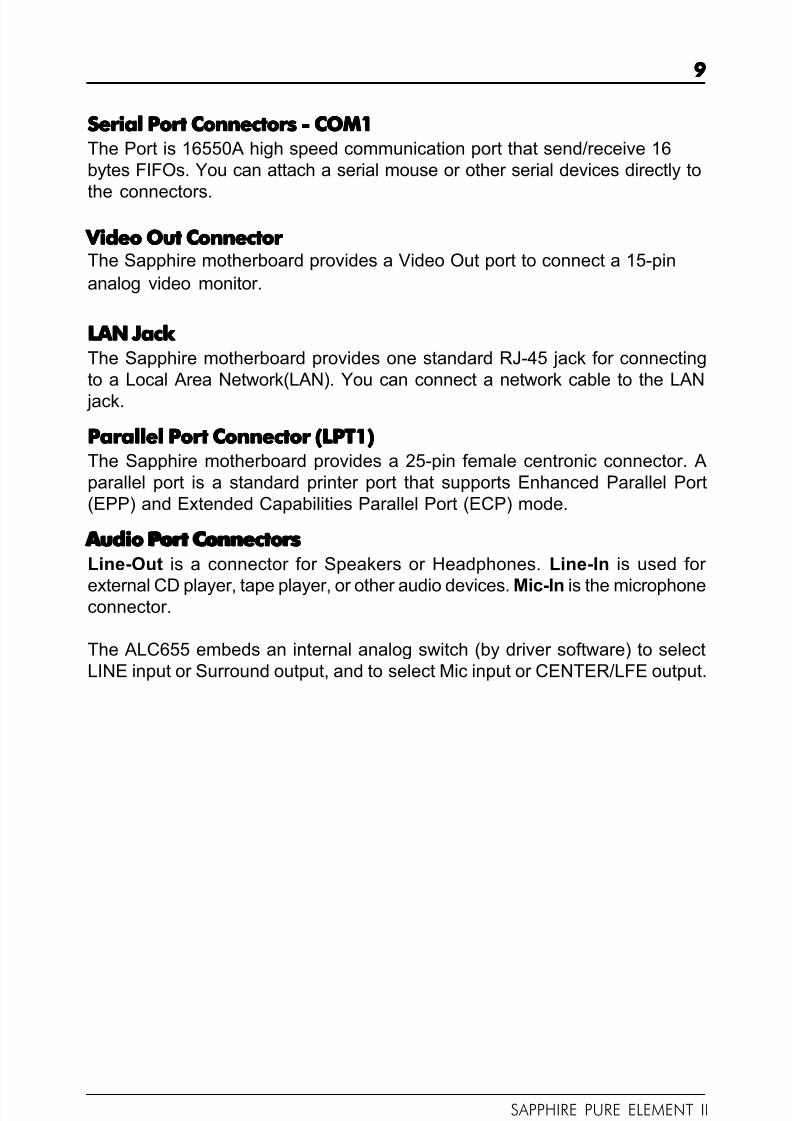
SAPPHIRE PURE ELEMENT II
J18
PIN Assignment
1 CD-L
2 GND
3 GND
4 CD-R
J18 - Pin Definition J18 - Pin Definition J18 - Pin Definition J18 - Pin Definition J18 - Pin Definition
J20 - Pin Definition J20 - Pin Definition J20 - Pin Definition J20 - Pin Definition J20 - Pin Definition
PIN Assignment
1 AUX-L
2 GND
3 GND
4 AUX-R
1
J20
1
CD-IN Header - J18CD-IN Header - J18CD-IN Header - J18CD-IN Header - J18CD-IN Header - J18This header allows for connection from the CD-ROM Drive.
AUX-IN Header - J20 AUX-IN Header - J20 AUX-IN Header - J20 AUX-IN Header - J20 AUX-IN Header - J20This header allows for connection from the Audio Device.
F O X C O N N
R E M O V E

8/4/2019 126 Manual
http://slidepdf.com/reader/full/126-manual 20/40
2020202020
PE-I7RC410M-2PE-I7RC410M-2PE-I7RC410M-2PE-I7RC410M-2PE-I7RC410M-2 User’s Manual
PIN Assignment1 MIC
2 GND
3 REF
4 POWER
5 Front Audio(R)
6 Rear Audio(R)
7 Reserved
8 Key(No pin)
9 Front Audio(L)10 Rear Audio(L)
FP-S1 - Pin DefinitionFP-S1 - Pin DefinitionFP-S1 - Pin DefinitionFP-S1 - Pin DefinitionFP-S1 - Pin Definition
101010101099999
2222211111
FPFPFPFPFP-----S1S1S1S1S1
Front Panel Audio Header - FP-S1Front Panel Audio Header - FP-S1Front Panel Audio Header - FP-S1Front Panel Audio Header - FP-S1Front Panel Audio Header - FP-S1This Sapphire motherboard supports front panel microphone Line In and LineOut ports. If your computer case has these ports, you can connect them to FP-S1.
Note: In order to utilize the front audio header, your chassis must have a
front audio connector. Also please make sure the pin assignment on the
cable is the same as the pin assignment on the motherboard header. To
find out if the chassis you are buying supports front audio connection,
please contact your dealer.
F O X C O N N
R E M O V E

8/4/2019 126 Manual
http://slidepdf.com/reader/full/126-manual 21/40
2121212121
SAPPHIRE PURE ELEMENT II
USB Headers - FP-U1, FP-U2This Sapphire motherboard has eight USB ports. Some computer caseshave a special module that mounts USB ports at the front of the case. If youhave this kind of case, use the auxiliary USB connector FP-U1/FP-U2 to con-
nect the front mounted ports to the Sapphire motherboard.
Front Panel Header - FP1The Sapphire motherboard provides a front panel connector for the frontpanel switches and LEDs. FP1 is compliant with the Front Panel I/O Connec-tivity Design Guide.
FP-U1, FP-U2 - Pin DefinitionFP-U1, FP-U2 - Pin DefinitionFP-U1, FP-U2 - Pin DefinitionFP-U1, FP-U2 - Pin DefinitionFP-U1, FP-U2 - Pin Definition
1010101010
99999
22222
11111
FP-U1FP-U1FP-U1FP-U1FP-U1
1010101010
99999
22222
11111
FP-U2FP-U2FP-U2FP-U2FP-U2
PIN SIGNAL
1 VCC
2 VCC
3 USBP0-
4 USBP1-5 USBP0+
6 USBP1+
7 GND
8 GND
9 KEY
10 OC#
FP1FP1FP1FP1FP1
NC
VCC
KEY
KEYLOCK
GND
IRRX
SPEAKER
GND
KEY
IRTX
NC
VCC
GND
KEY
GND
PWR_SW
RESET
NC
KEY
GND
PW_LED-
PW_LED+
HDD_LED-
HDD_LED+
24 23
16
1718
20
22 21
19
15
13
7
11
9
5
3
1
14
6
8
10
12
2
4
F O X C O N N
R E M O V E
F O X C O N N
R E M O V E

8/4/2019 126 Manual
http://slidepdf.com/reader/full/126-manual 22/40
2222222222
PE-I7RC410M-2PE-I7RC410M-2PE-I7RC410M-2PE-I7RC410M-2PE-I7RC410M-2 User’s Manual
PIN SIGNAL
1 GND
2 TXP
3 TXN
4 GND
5 RXN
6 RXP
7 GND
S A T A 1
S A T A 2
Serial A Serial A Serial A Serial A Serial A TTTTT A Hard Disk Connectors - SA A Hard Disk Connectors - SA A Hard Disk Connectors - SA A Hard Disk Connectors - SA A Hard Disk Connectors - SA TTTTT A1, SA A1, SA A1, SA A1, SA A1, SA TTTTT A2 A2 A2 A2 A2
The Sapphire motherboard has two SATA connectors. Each supports
1st
generation SATA data rates of 150 MB/s. Both connectors are fullycompliant with Serial ATA 1.0 specifications. Each SATA connector can
connect to one hard disk device. Please refer to SATA Raid setup (Page 37) for
details on software installation procedure.
F O X C O N N
R E M O V E

8/4/2019 126 Manual
http://slidepdf.com/reader/full/126-manual 23/40
2323232323
SAPPHIRE PURE ELEMENT II
Serial A Serial A Serial A Serial A Serial A TTTTT A Cable A Cable A Cable A Cable A Cable
Serial A Serial A Serial A Serial A Serial A TTTTT A Hard Disk Devices P A Hard Disk Devices P A Hard Disk Devices P A Hard Disk Devices P A Hard Disk Devices Power Cable(optional)ower Cable(optional)ower Cable(optional)ower Cable(optional)ower Cable(optional)
Connect one end of the SATA cable to the Sapphire motherboard, and connect
the other end to the SATA Hard Disk.
Please do not fold the serial ATA cable at a 90-degree angle as thiswill cause a loss of data during the transmission.

8/4/2019 126 Manual
http://slidepdf.com/reader/full/126-manual 24/40
2424242424
PE-I7RC410M-2PE-I7RC410M-2PE-I7RC410M-2PE-I7RC410M-2PE-I7RC410M-2 User’s Manual
1JP9
Clear CMOS Jumper - JP9Clear CMOS Jumper - JP9Clear CMOS Jumper - JP9Clear CMOS Jumper - JP9Clear CMOS Jumper - JP9If you want to clear the system configuration, use the JP9 (Clear CMOS Jumper)
to clear data.
JP9 Selection
1-2* Normal*
2-3 CMOS Clear
Close Open * = Default setting.
JP2-Onboard AC97 Sound Select JP2-Onboard AC97 Sound Select JP2-Onboard AC97 Sound Select JP2-Onboard AC97 Sound Select JP2-Onboard AC97 Sound Select
JP2 Function
1-2* AC97 Sound Enable*
2-3 AC97 Sound Disable
1JP2
JP13
JP13-Onboard LAN Select (optional) JP13-Onboard LAN Select (optional) JP13-Onboard LAN Select (optional) JP13-Onboard LAN Select (optional) JP13-Onboard LAN Select (optional)
JP13 Function
1-2* LAN Enable*
2-3 LAN Disable
1
JUMPER SETTING JUMPER SETTING JUMPER SETTING JUMPER SETTING JUMPER SETTINGThe Sapphire motherboard provides jumpers enabling configuration of thehardware.
F O X C O N N
R E M O V E

8/4/2019 126 Manual
http://slidepdf.com/reader/full/126-manual 25/40
2525252525
SAPPHIRE PURE ELEMENT II
PCI-E x16 SlotPCI-E x16 SlotPCI-E x16 SlotPCI-E x16 SlotPCI-E x16 Slot
PCI SlotsPCI SlotsPCI SlotsPCI SlotsPCI Slots
SLOTSSLOTSSLOTSSLOTSSLOTSThe Sapphire motherboard provides one PCI-E x16 slot and two 32-bit PCIslots.
PCI Express x16 Graphics Interface• One 16-lane (x16 port) PCI Express port intended for external
graphics.
• Fully compliant to the PCI Express Base Specification revision 1.0a.
• The base PCI Express frequency of this interface is 4GB/s.• PCI Express support an enhanced addressing mechanism.
PCI (Peripheral Component Interconnect) Slots• Two 32-bit PCI ports for add-in card connections.
F O X C O N N
R E M O V E

8/4/2019 126 Manual
http://slidepdf.com/reader/full/126-manual 26/40
2626262626
PE-I7RC410M-2PE-I7RC410M-2PE-I7RC410M-2PE-I7RC410M-2PE-I7RC410M-2 User’s Manual
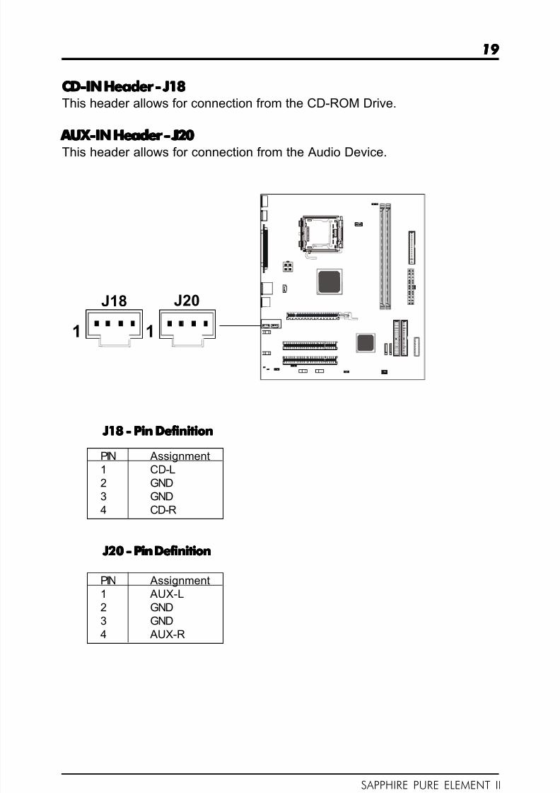
CPU INSTCPU INSTCPU INSTCPU INSTCPU INST ALLA ALLA ALLA ALLA ALLA TIONTIONTIONTIONTIONPlease refer to the steps below to install the CPU.
1.Please turn off the power andunplug the power cord beforeinstalling the CPU. Use your indexfinger and thumb, unhook the metallever from the bottom steel shell griphook.
2.Use the index finger to lift the topsteel shell.
3. Place the CPU onto the plasticbody (Look for the gold arrow, thegold arrow should point away fromthe lever pivot).
8/4/2019 126 Manual
http://slidepdf.com/reader/full/126-manual 27/40
27 27 27 27 27
SAPPHIRE PURE ELEMENT II
4.Press the metal lever down toforce the cap to be pushed up bythe CPU; This may also be done byremoving the lid beforehand.
5. Press the metal lever down andhook it to the bottom steel shell griphook.
8/4/2019 126 Manual
http://slidepdf.com/reader/full/126-manual 28/40
2828282828
PE-I7RC410M-2PE-I7RC410M-2PE-I7RC410M-2PE-I7RC410M-2PE-I7RC410M-2 User’s Manual
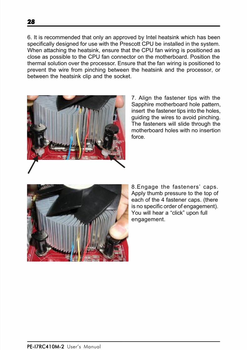
6. It is recommended that only an approved by Intel heatsink which has beenspecifically designed for use with the Prescott CPU be installed in the system.When attaching the heatsink, ensure that the CPU fan wiring is positioned asclose as possible to the CPU fan connector on the motherboard. Position the
thermal solution over the processor. Ensure that the fan wiring is positioned toprevent the wire from pinching between the heatsink and the processor, or between the heatsink clip and the socket.
7. Align the fastener tips with theSapphire motherboard hole pattern,insert the fastener tips into the holes,guiding the wires to avoid pinching.
The fasteners will slide through themotherboard holes with no insertionforce.
8.Engage the fasteners’ caps.Apply thumb pressure to the top of each of the 4 fastener caps. (thereis no specific order of engagement).You will hear a “click” upon fullengagement.

8/4/2019 126 Manual
http://slidepdf.com/reader/full/126-manual 29/40
2929292929
SAPPHIRE PURE ELEMENT II
9. Gently rotate the cap clockwise1/4 turn to fasten the heatsink ontothe Sapphire motherboard.
10. Lastly, attach the fan wireconnector to the 4 pin fan header connector on the Sapphiremotherboard labeled CPU FAN.
8/4/2019 126 Manual
http://slidepdf.com/reader/full/126-manual 30/40
3030303030
PE-I7RC410M-2PE-I7RC410M-2PE-I7RC410M-2PE-I7RC410M-2PE-I7RC410M-2 User’s Manual
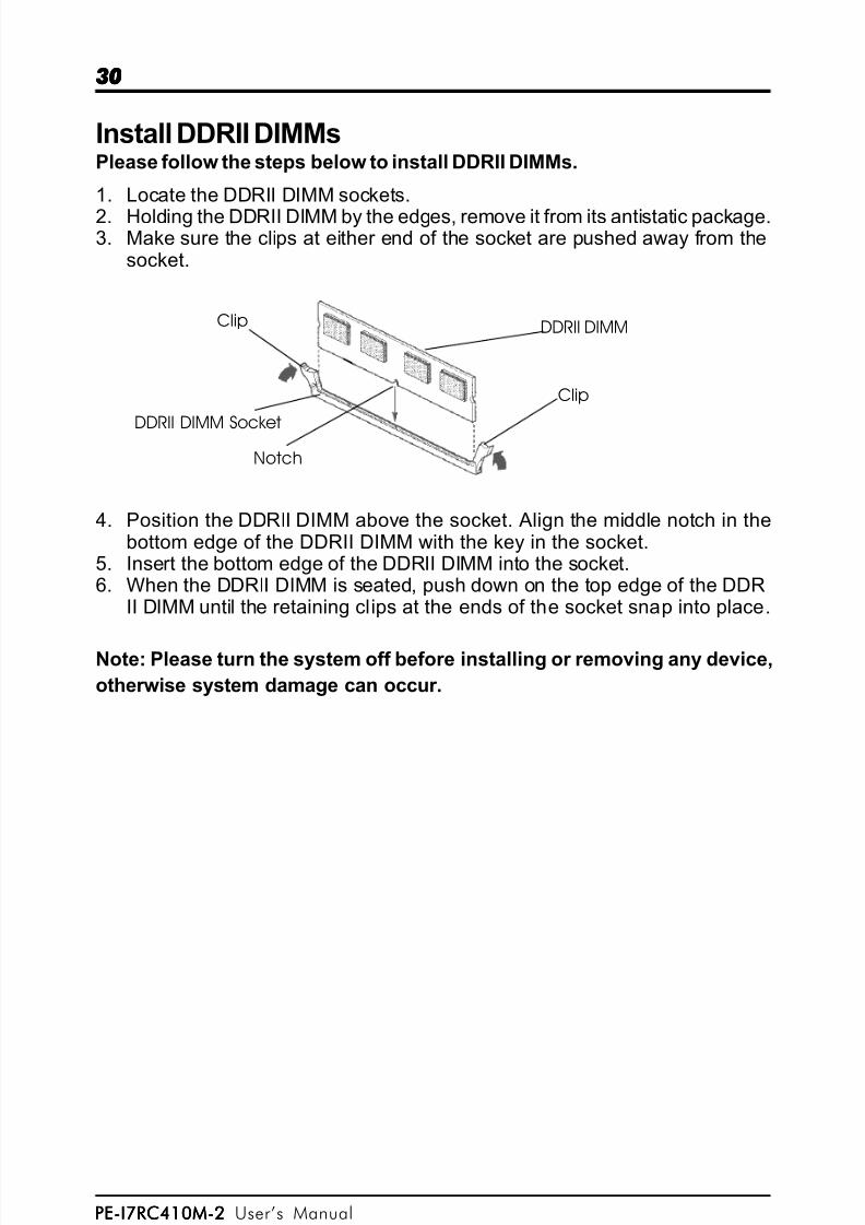
Clip
Clip DDRII DIMM
DDRII DIMM Socket
Notch
Install DDRII DIMMsPlease follow the steps below to install DDRII DIMMs.
1. Locate the DDRII DIMM sockets.
2. Holding the DDRII DIMM by the edges, remove it from its antistatic package.3. Make sure the clips at either end of the socket are pushed away from the
socket.
4. Position the DDRII DIMM above the socket. Align the middle notch in thebottom edge of the DDRII DIMM with the key in the socket.
5. Insert the bottom edge of the DDRII DIMM into the socket.6. When the DDRII DIMM is seated, push down on the top edge of the DDR
II DIMM until the retaining clips at the ends of the socket snap into place.
Note: Please turn the system off before installing or removing any device,
otherwise system damage can occur.

8/4/2019 126 Manual
http://slidepdf.com/reader/full/126-manual 31/40
3131313131
SAPPHIRE PURE ELEMENT II
BIOS SETUP
About the Setup Utility
The motherboard uses the latest Award BIOS with support for Windows Plugand Play. The CMOS chip on the motherboard contains the ROM setup instruc-tions for configuring the motherboard BIOS.
The BIOS (Basic Input and Output System) Setup Utility displays the system’sconfiguration status and provides you with options to set system parameters.The parameters are stored in battery-backed-up CMOS RAM that saves thisinformation when the power is turned off. When the system is turned back on,the system is configured with the values you stored in CMOS.
The BIOS Setup Utility enables you to configure:
Hard drives, diskette drives and peripherals
Video display type and display options
Password protection to prevent unauthorized use
Power Management features
The settings made in the Setup Utility affect how the computer performs.Before using the Setup Utility, ensure that you understand the Setup Utilityoptions.
This chapter provides explanations for Setup Utility options.
The Standard ConfigurationA standard configuration has already been set in the Setup Utility. However, werecommend that you read this chapter in case you need to make any changesin the future.
This Setup Utility should be used:- when changing the system configuration- when a configuration error is detected and you are prompted to make
changes to the Setup Utility- when trying to resolve IRQ conflicts- when making changes to the Power Management configuration- when changing the password or making other changes to the Security
Setup
Entering the Setup UtilityWhen you power on the system, BIOS enters the Power-On Self Test (POST)routines. POST is a series of built-in diagnostics performed by the BIOS. After the POST routines are completed, the following message appears:

8/4/2019 126 Manual
http://slidepdf.com/reader/full/126-manual 32/40
3232323232
PE-I7RC410M-2PE-I7RC410M-2PE-I7RC410M-2PE-I7RC410M-2PE-I7RC410M-2 User’s Manual
Main MenuMain MenuMain MenuMain MenuMain Menu
Once you enter the Award BIOS CMOS Setup Utility, the Main Menu will appear on the
screen. It allows you to select from various setup functions and two exit choices. Use
the arrow keys to select among the items and press <Enter> to accept and enter the sub-
menu.
Phoenix - Award WorkstationBIOS CMOS Setup Utility
Standard CMOS Features Frequency/Voltage Control
Advanced BIOS Features Load Fail-Safe Defaults
Advanced Chipset Features Load Optimized Defaults
Integrated Peripherals Set Supervisor Password
Power Management Setup Set User Password
PnP/PCI Configurations Save & Exit Setup
PC Health Status Exit Without Saving
Esc : Quit : Select Item
F10 : Save & Exit Setup
Time, Date, Hard Disk Type ... ...
(Note : The sample BIOS Setup Menu included here only shows a typical case,
and may not be exactly the same as the one on your unit.)
Note that a brief description of each highlighted item will appear at the bottom of the
screen.
Standard This setup page includes all the items of Award™ special standard
CMOS Features features.
Advanced BIOS This setup page includes all the items of Award™ special enhanced
Features features.
Advanced This setup page includes all the items of chipset special features.
Chipset Features
Integrated This section page includes all the items of IDE hard drive and
Peripherals Programmed Input / Output features.
Power This entry only appears if your system supports Power
Management Management “Green PC” standards.
Setup
PnP/PCI This entry appears if your system supports PnP/PCI.
Configurations
PC Health Status Display CPU and Case Fan Speed, temperature, etc.
Frequency/ CPU speed setting are settings of CPU speed. You should
Voltage Control refer to your CPU marking.

8/4/2019 126 Manual
http://slidepdf.com/reader/full/126-manual 33/40
3333333333
SAPPHIRE PURE ELEMENT II
Load Fail-Safe The BIOS defaults have been set by Sapphire and represent
Defaults settings which provide the minimum requirements for your system
to operate.
Load Optimized These chipset defaults are settings which provide for maximumDefaults system performance. Sapphire has assigned these values to
provide optimized performance.
Set Supervisor/ Changes, sets, or disables password. It allows you to limit
User Password access to the system and the Setup Program.
Save & Exit Saves value changes to CMOS and exits setup.
Setup
Exit Without Abandons all CMOS value changes and exits setup.Saving
Standard CMOS FeaturesStandard CMOS FeaturesStandard CMOS FeaturesStandard CMOS FeaturesStandard CMOS FeaturesThe options in Standard CMOS Setup Menu are divided into 10 categories. Each category
includes one or more setup items. Use the arrow keys to highlight the item and then use
the <PgUp> or <PgDn> key to select the desired value in each item.
Phoenix - Award WorkstationBIOS CMOS Setup UtilityStandard CMOS Features
Date (mm :d d : y y ) Sat. Jan 01 2005 Item Help
Time (h h :mm:ss ) 11 : 1 : 35
Menu Level
IDE Primary Master [Press Enter 4303 MB]
IDE Primary Slave [None] Change the day, month,
IDE Secondary Master [None] year and century
IDE Secondary Slave [None]
Drive A [1.44M, 3.5 in.]
Drive B [None]
Video [EGA/VGA]
Halt on [All, but keyboard]
Base Memory 640K
Extended Memory 30720K
Total Memory 31744K
Move Enter : Select +/-/PU/PD : Value F10 : Save ESC : Exit F1 :General Help
F5 : Previous Values F6 : Fail-Safe Defaults F7 : Optimized Defaults
(Note : The sample BIOS Setup Menu included here only shows a typical case,
and may not be exactly the same as the one on your unit.)

8/4/2019 126 Manual
http://slidepdf.com/reader/full/126-manual 34/40
3434343434
PE-I7RC410M-2PE-I7RC410M-2PE-I7RC410M-2PE-I7RC410M-2PE-I7RC410M-2 User’s Manual
Date The date format is <day-of-the-week> <month> <day> <year>.
Time The time format is <hour> <minute> <second> displayed in
24-hour system.
Primary and Your computer has two IDE channels: primary and secondary.Secondary And each channel can be installed with one or two devices
Master, Slave (master and slave). Use these options to configure ach device.
Drive A Type / This category identifies the driver types which have been
Drive B Type installed in the computer.
Video The default setting is EGA/VGA.
Halt on You can select which type of error will cause the system to halt.
Advanced BIOS Features Advanced BIOS Features Advanced BIOS Features Advanced BIOS Features Advanced BIOS FeaturesThis section allows you to configure your system for basic operation. You have the
opportunity to select the system’s default speed, boot-up sequence, keyboard operation,
shadowing and security.
Advanced Chipset Features Advanced Chipset Features Advanced Chipset Features Advanced Chipset Features Advanced Chipset FeaturesThe Chipset Features Setup option is used to change the values of the chipset registers.
These registers control most of the system options in the computer.
This section allows you to configure the system based on the specific features of theinstalled chipset. This chipset manages bus speeds and access to system memory
resources, such as DRAM and the external cache. It must be stated that these items
should not be altered. The default settings have been chosen because they provide the
best operating conditions for your system.
Integrated PeripheralsIntegrated PeripheralsIntegrated PeripheralsIntegrated PeripheralsIntegrated PeripheralsThe Integrated Peripherals Setup allows the user to configure the onboard IDE controller,
floppy disk controller, the printer port and the serial ports.
Power Management SetupPower Management SetupPower Management SetupPower Management SetupPower Management SetupThe Power Management Setup Menu allows you to configure your system to save the
most energy while operating in a manner consistent with your own style of computer
use.
PnP/PCI ConfigurationsPnP/PCI ConfigurationsPnP/PCI ConfigurationsPnP/PCI ConfigurationsPnP/PCI ConfigurationsThis section describes how to configure the PCI bus system. This section covers some
very technical items and it is recommended that only experienced users should make
any changes to the default settings.
PC Health StatusPC Health StatusPC Health StatusPC Health StatusPC Health StatusThe PC Health Status displays CPU and Case Fan Speed.
8/4/2019 126 Manual
http://slidepdf.com/reader/full/126-manual 35/40
3535353535
SAPPHIRE PURE ELEMENT II
Set Supervisor/User Password
When this function is selected, the following message appears at the center of the screen to assist you in creating a password.
ENTER PASSWORD
Type the password, up to eight characters, and press <Enter>. The passwordtyped now will clear any previously entered password from CMOS memory.You will be asked to confirm the password. Type the password again andpress <Enter>. You may also press <Esc> to abort the selection. To disablepassword, just press <Enter> when you are prompted to enter password. Amessage will confirm the password being disabled. Once the password isdisabled, the system will boot and you can enter BIOS Setup freely.
PASSWORD DISABLED
If you have selected “System” in “Security Option” of “BIOS Features Setup”menu, you will be prompted for the password every time the system rebootsor any time you try to enter BIOS Setup. If you have selected “Setup” at “Secu-rity Option” from “BIOS Features Setup” menu,you will be prompted for thepassword only when you enter BIOS Setup.
Supervisor Password has higher priority than User Password. You can useSupervisor Password when booting the system or entering BIOS Setup tomodify all settings. Also you can use User Password when booting the sys-tem or entering BIOS Setup but can not modify any setting if Supervisor Pass-word is enabled.
Save & Exit Setup
Navigate to this option and press <Enter> to save the changes that you havemade in the Setup Utility and exit the Setup Utility. When the Save and Exitdialog box appears, press <Y> to save and exit, or press <N> to return to themain menu.
Exit Without Saving
Navigate to this option and press <Enter> to discard any changes that youhave made in the Setup Utility and exit the Setup Utility. When the Exit WithoutSaving dialog box appears, press <Y> to discard changes and exit, or press<N> to return to the main menu.
Note: If you have made settings that you do not want to save, use the “Exit
Without Saving” item and press <Y> to discard any changes you have

8/4/2019 126 Manual
http://slidepdf.com/reader/full/126-manual 36/40
3636363636
PE-I7RC410M-2PE-I7RC410M-2PE-I7RC410M-2PE-I7RC410M-2PE-I7RC410M-2 User’s Manual
BIOS Update ProcedureThe program AWDFLASH.EXE is included on the driver CD (D:\Utility\AWDFLASH.EXE). It is recommended to follow the procedure below to update
the BIOS.
1. Create a DOS-bootable floppy diskette. Copy the new BIOS file (justobtained or downloaded) and the utility program AWDFLASH.EXE to the dis-kette.2. Allow the PC system to boot from the DOS diskette.3. At the DOS prompt, type
AWDFLASH<ENTER>
4. Enter the file name of the new BIOS.5. The question: “Do you want to save BIOS (Y/N)?” is displayed.
Press “N” if there is no need to save the existing BIOS.Press “Y” if a backup copy of the existing BIOS is needed.(A file name has to be assigned to the existing BIOS binary file.)
6. The message : “Press “Y” to program or “N” to exit” is displayed. Type
“Y” <ENTER>
7. Wait until the flash-update is completed.8. Restart the PC.
Warning : - Do not turn off or RESET the computer during the flashprocess.
- If you are not sure how to upgrade the BIOS, please takeyour computer to an Authorized Service Center and havea trained technician do the work for you.
8/4/2019 126 Manual
http://slidepdf.com/reader/full/126-manual 37/40
37 37 37 37 37
SAPPHIRE PURE ELEMENT II
SATA RAID USER MANUAL
Creating and deleting RAID sets is a function found in the BIOS. During bootup, the
following message will appear, pausing for a few moments to allow the user to
choose what to do:
Press Ctrl+S or F4 to enter RAID utility
An easy-to-use screen will appear with the following choices in the top left:
Create RAID Set
Delete RAID Set
Rebuild RAID SetResolve Conflicts
Below this will be listed the drives currently installed on the system.
The top right half of the screen displays directions and comments for the user. The
bottom right half lists the command keys:
Arrows up and down are Select Keys
ESC takes the user to the previous menuEnter selects the user’s choice
Ctrl-E exits the utility
Creating RAID Sets
Becuase SATA Raid supports two drives, creating RAID Sets is a simple procedure.
1. Select “Create RAID Set.”
2. Choose either a “Striped” or “Mirrored” RAID Set.
3. Select if you want the utility to Auto Configure the RAID Set or if you want to manually
configure the RAID Set. For Striped Sets, you can change the chunk size. For
Mirrored Sets, you assign which is the Source and Target drives, as well as if you
want Disk Copy.
8/4/2019 126 Manual
http://slidepdf.com/reader/full/126-manual 38/40
3838383838
PE-I7RC410M-2PE-I7RC410M-2PE-I7RC410M-2PE-I7RC410M-2PE-I7RC410M-2 User’s Manual
What is Disk Copy? If the disk assigned as the source disk has already been
partitioned and has data stored on it, and then a second disk is added for redundancy,
the data on the source drive can be copied to the destination drive, so that the disks
are identical, and all subsequent data will be written to both drives as a Mirrored set.If, however, the source disk does not have data already stored on it, there is no need
for Disk Copy.
4. The utility will ask “Are You Sure?” before completing the configuration.
Deleting RAID Sets
1. To remove one or more RAID sets, select “Delete RAID Set.”
2. Select desired set and press Y when asked “Are You Sure?”
Resolving Conflict
When a RAID set is created, the metadata written to the disk includes drive connection
information (Primary Chanel, Secondary Channel). If, after a disk failure, the replacement
disk was previously part of a RAID set (or used in another system), it may have conflicting
metadata, specifically in reference to the drive connection information. If so, this will
prohibit the RAID set from being either created or rebuilt. In order for the RAID set to
function properly, this old metadata must be first overwritten with the new metadata.
To resolve this, select “Resolve Conflict” and the correct metadata, including the correct
drive connection information, will be written to the replacement disk.
8/4/2019 126 Manual
http://slidepdf.com/reader/full/126-manual 39/40
3939393939
SAPPHIRE PURE ELEMENT II
DRIVER AND RAID SOFTW DRIVER AND RAID SOFTW DRIVER AND RAID SOFTW DRIVER AND RAID SOFTW DRIVER AND RAID SOFTW ARE INST ARE INST ARE INST ARE INST ARE INST ALLA ALLA ALLA ALLA ALLA TIONTIONTIONTIONTION
Microsoft Windows Driver Installation
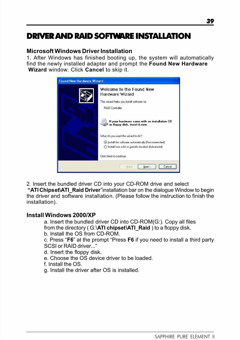
1. After Windows has finished booting up, the system will automaticallyfind the newly installed adapter and prompt the Found New HardwareWizard window. Click Cancel to skip it.
2. Insert the bundled driver CD into your CD-ROM drive and select“ATI Chipset\ATI_Raid Driver ”installation bar on the dialogue Window to beginthe driver and software installation. (Please follow the instruction to finish theinstallation).
Install Windows 2000/XPa. Insert the bundled driver CD into CD-ROM(G:). Copy all filesfrom the directory ( G:\ATI chipset\ATI_Raid ) to a floppy disk.b. Install the OS from CD-ROM.
c. Press “F6” at the prompt “Press F6 if you need to install a third partySCSI or RAID driver...”d. Insert the floppy disk.e. Choose the OS device driver to be loaded.f. Install the OS.g. Install the driver after OS is installed.

8/4/2019 126 Manual
http://slidepdf.com/reader/full/126-manual 40/40
40 40 40 40 40
APPENDIX APPENDIX APPENDIX APPENDIX APPENDIX Note to User:Note to User:Note to User:Note to User:Note to User:The bundled driver CD contains all the drivers that the Sapphire
motherboard needs. Each driver will install automatically once it is selected.Please select the drivers that you want to install by clicking on the driver’s
button.
Related Documents