U.S. Deportment 1200 New Jersey Ave., SE of Transportation Federal Highway December 17, 20 13 Washington, D.C. 20590 Administration In Reply Refer To: HSST/ B-245 Mr. Mathew Harriman Hill and Smith, Ltd. Bilston, Wolverhampton West Midlands, WV14 OQL United Kingdom Dear Mr. Harriman: This letter is in response to your request for the Federal Highway Administration (FHWA) to review a roadside safety system for eligibility for reimbursement under the Federal-aid hi ghway program. Name of system: Brifen Wire Rope Safety Fence 0-Post, MASH Type of system: Longitudinal Barrier Test Level: AASHTO MASH TL3 Testing conducted by: Southwest Research Institute (SwRI) Task Force 13 Designator: SGM37 Date of request: October 6, 2013 Date of completed package: November 15, 20 13 Decision: The following device is eligible, with deta il s provided in the fo rm which is attached as an integral part of this letter: • Bri fe n Wire Rope Safety Fence 0-Post, MASH Based on a review of crash test results you submitted certifying the device described herein meets the crash test and evaluation criteria of the American Associ at ion of State Highway and Transportation Officials' Manual for Assessing Safety Hardware (MASH), the device is eligible for reimbursement under the Federal-aid hi ghway program. Eli gibility for reimbursement under the Federal-aid hi ghway program does not establi sh approval or endorsement by the FHW A for any particular purpose or use. The FHW A, the Department of Transportation, and the United States Government do not endorse products or services and the issuance of a reimbursement e li gibility letter is not an endorsement of any product or servic e.

Welcome message from author
This document is posted to help you gain knowledge. Please leave a comment to let me know what you think about it! Share it to your friends and learn new things together.
Transcript

US Deportment 1200 New Jersey Ave SE of Transportation
Federal Highway December 1 7 2013
Washington DC 20590
Administration In Reply Refer To
HSST B-245
Mr Mathew Harriman Hill and Smith Ltd Bilston Wolverhampton West Midlands WV14 OQL United Kingdom
Dear Mr Harriman
This letter is in response to your request for the Federal Highway Administration (FHWA) to review a roadside safety system for eligibility for reimbursement under the Federal-aid highway program
Name of system Brifen Wire Rope Safety Fence 0-Post MASH Type of system Longitudinal Barrier Test Level AASHTO MASH TL3 Testing conducted by Southwest Research Institute (SwRI) Task Force 13 Designator SGM37 Date of request October 6 2013 Date of completed package November 15 20 13
Decision The following device is eligible with details provided in the form which is attached as an integral part of this letter
bull Brifen Wire Rope Safety Fence 0-Post MASH
Based on a review of crash test results you submitted certify ing the device described herein meets the crash test and evaluation criteria of the American Association of State Highway and Transportation Officials Manual for Assessing Safety Hardware (MASH) the device is eligible for reimbursement under the Federal-aid highway program Eligibility for reimbursement under the Federal-aid highway program does not establi sh approval or endorsement by the FHW A for any particular purpose or use
The FHW A the Department of Transportation and the United States Government do not endorse products or services and the issuance of a reimbursement eligibility letter is not an endorsement of any product or service
2
Requirements To be found eligible for Federal-aid funding roadside safety devices should meet the crash test and evaluation criteria contained in the American Association of State Highway and Transportation Officials Manual for Assessing Safety Hardware (MASH)
Description The device and supporting documentation are described in the attached form
Summary and Standard Provisions Therefore the system described and detailed in the attached form is eligible for reimbursement and may be installed under the range of conditions tested Please note the following standard provisions that apply to FHWA eligibility letters
bull This letter provides a AASHTOARTBAAGC Task Force 13 designator that should be used for the purpose of the creation of a new andor the update of existing Task Force 13 drawing for posting on the on-line Guide to Standardized Highway Barrier Hardware currently referenced in AASHTO Roadside Design Guide
bull This finding ofeligibility does not cover other structural features of the systems nor conformity with the Manual on Uniform Traffic Control Devices
bull Any changes that may influence system conformance with MASH will require a new reimbursement eligibility letter
bull Should the FHWA discover that the qualification testing was flawed that in-service performance reveals safety problems or that the system is significantly different from the version that was crash tested we reserve the right to modify or revoke this letter
bull You are expected to supply potential users with sufficient information on design and installation requirements to ensure proper performance
bull You are expected to certify to potential users that the hardware furnished has the same chemistry mechanical properties and geometry as that submitted for review and that it will meet the test and evaluation criteria of the MASH
bull To prevent misunderstanding by others this letter of eligibility is designated as number B-245 and shall not be reproduced except in full This letter and the test documentation upon which it is based are public information A ll such letters and documentation may be reviewed at our office upon request
bull This letter shall not be construed as authorization or consent by the FHWA to use manufacture or sell any patented system for which the applicant is not the patent holder The FHWA does not become involved in issues concerning patent law Patent issues if any are to be resolved by the applicant
3
bull Because it is a steel product the Brifen Wire Rope Safety Fence 0-Post MASH is subject to Section 635410 (Buy America) of Title 23 US Code of Federal Regulations and cannot be permanently incorporated into any federally funded project unless it is made in the US from US steel
Sincerely yours
Michael S Griffith Director Office of Safety Technologies Office of Safety
Enclosures
Version 70 (313) Page 1 of 3
Request for Federal Aid Reilnbursement Eligibility Of Highway Safety Hardware
October 6 2013 Ci New (ResubmissionDate of Request I Name Man Harriman js19nature Alf-I-- middot LOmpany -Iigt Hill and Smith Ltd
~ Address Bilston Wolverhampton West Midlands WV14 OQLE
QJ Country UKII)
Michael S Griffith DirectorTo FHWA Office of Safety Technologies
I request the following devices be considered eligible for reimbursement under the Federal-aid highway program
System Type Submission Type Device Name I Variant Testing Criterion Test Level
6 Barriers (Roadside Median Bridge Rafllngs)
(9 Physical Crash Testing
( FEA ampVampV Analysis Brifen Wire Rope Safely Fence
AASHTOMASH TL3
By submitting this request for reviuw and evaluation by the Federal Highway Administration I certify
t hat the product(s) was (were) tested in conformity with the AASHTO Manual for Assessing Safety
Hardware and that the evaluation results meet the appropriate evaluation criteria In the MASH
Identification of the lndlvldual or organization responsible for the product
Contact Name Matt Harriman Sarne as Submitter fgJ
Company Name Hill and Smith Ltd Same as Submitter C8J Address Bilston Wolverhampton West Midlands WVl 4 OQL Same as Submitter C8J Country UK Same as Submitter C8J
PRODUCT DESCRIPTION
New Hardware
Version 70 (313) Page 1 of 3
Request for Federal Aid Reimbursement Eligibi lity Of Highway Safety Hardware
Date of Request October 6 2013 r New ( Resubmission
Name Matt Harriman Signature QI t middote c s
Company
Address
Country
Hill and Smith Ltd
Bilston Wolverhampton West Midlands WVl 4 OQL
UK
To Michael S Griffith Director FHWA Office of Safety Technologies
I request the following devices be considered eligible for reimbursement under the Federal-aid highway program
System Type Submission Type Device Name I Variant Testing Criterion Test Level
B Barriers (Roadside (9 Physical Crash Testing Brifen Wire Rope Safety AASHTOMASH TL3
Median Bridge Railings) ( FEA amp VampV Analysis Fence
By submitting this request for review and evaluation by the Federal Highway Administration I certify
that the product(s) was (were) tested in conformity with the AASHTO Manual for Assessing Safety
Hardware and that the evaluation resu lts meet the appropriate evaluation criteria in the MASH
Identification of the individual or organization responsible for the product
Contact Name Matt Harriman Same as Submitter l8J Company Name Hill and Smith Ltd Same as Submitter l8J Address Bilston Wolverhampton West Midlands WVl 4 OQL Same as Submitter 18J
Country UK Same as Submitter l8J
PRODUCT DESCRIPTION
New Hardware
Version 70 (313) Page 2 of 3
The Brifen MASH TL-3 WRSF is a high tension cable barrier that consists four (4) separate wire ropes (cables) interwoven between 0-shaped steel posts The ropes are held at the design height by notchesdimples with a rope retention device (plastic) in the side of the 0 -shaped steel posts The total length of the WRSF used in the test was approximately 183 m (600 ft) and it was anchored at each end using Brifens WRGT-RD terminals The WRGT-RD terminal was previously accepted to NCHRP 350 Test Level Three (TL-3) by the FHWA (letter HAS-1 OCC-86A dated August 10 2005)
Each of the four wire ropes are 075 in (19 mm) in diameter pre-stretched galvanized steel 3 x 7 construction with a minimum breaking strength of 39000 lbs (1735 kN) and have a modulus of elasticity after pre-stressing of 1180500 psi (8300 kgmm2) Nominal rope heights (center of rope) are top 35 in (890 mm) upper middle 28 in (710 mm) lower middle 21 in (530 mm) and bottom 14 in (355 mm) The posts in the test section are round HSS2875x0 132 and are inserted in steel sockets The post embedment into the steel socket is 1 2 in (305 mm) The steel sockets were placed in 12 in (305 mm) diameter concrete footers through the concrete pavement The first four posts were spaced at 65 ft (20 m) as part of the WRGT-RD anchor and the length of need line posts were spaced at a minimum distance of 7 ft (21 m) and a maximum distance of 21 ft (64 m) depending on the test
Rigging screws were purposely arranged so they would be located in the area where vehicle-barrier contact occurs to demonstrate that their location does not affect barrier performance
We request the following for eligibility
I Brifen MASH TL-3 Cable Barrier 4-cable system for use with 0 -Post spacing of 7 ft (2 1 m) through 21 ft (64 m)
All systems can utilize pre-stretched or non pre-stretched cables (ropes) socketed posts in concrete footings driven posts surface mounted posts post cast directly into concrete and driven post sockets (The sockets are manufactured from either plastic or steel)
CRASH TESTING A brief description of each crash test and its result
Required Test Number
Narrative Description
Evaluation Results
3-10 (llOOC) Test 1 SwRI Test No BUSA-OP-03 I Test Date May 23 2012 7 post spacing (Impact between posts)
PASS
3-1 1 (2270P)
Test 2 SwRI Test No BUSA-OP-1Test Date May 22 2012 - 7 post spacing (Impact on post - establish minimum deflection) Test 3 SwRI Test No BUSA-OP-2Test Date May 22 2012 - 21 post spacing (Impact on post - establish maximum deflection)
PASS
3-20 (11 OOC)
3-21 (2270P)
Full Scale Crash Testing was done in compliance with MASH by the following accredited crash test
laboratory (cite the laboratorys accreditation status as noted in the crash test reports)
Version 70 (3 13) Page 3 of 3
Laboratory Name Southwest Research Institute
Laboratory Contact Karol Hricisak I Jenny Ferren Same as Submitter D Address 6220 Culebra Road San Antonio Texas 78228 Same as Submitter D Country USA Same as Submitter D Accreditation Certificate Number and Date
A21a Certificate Number 111002 March 31 2014
ATTACHMENTS Attach to this form
1) A copy of the full test report video and a Test Data Summary Sheet for each test conducted in
support of this request
2) A drawing or drawings ofthe device(s) that conform to the Task Force-13 Drawing Specifications
[Hardware Guide Drawing Standards] For proprietary products a single isometric line drawing is
usually acceptable to illustrate the product w ith detailed specifications intended use and contact
information provided on the reverse Additional drawings (not in TF-13 format) show ing details that
are key to understanding the performance of the device should also be submitted to facilitate our
review
FHWA Official Business Only
Eligibility Letter
Number Date
B-245 November 19 201 3
AASHTO TF13
Designator Key Words
Longitudinal Barrier Wire Rope Interwoven OShaped Steel Posts NCH RP 350 Test Level Three
21 - o
- (MAX)--il CABLE
II I
ELEVATION
I REFLECTOR ( i IF REQUIRED)
~-------in POST CAP (1 PLASTIC IF REQUIRED)
1r=RETAINER ( 4 PLASTIC)
35
50 Tr f deg I
ltfgtlt ~ = = -(_-(lt
12 l ~ REINFORC1NG RllG ( ) (IF REQUIRED)
-------+----~~-
~
VALRIES 1 SOCKET
bull bull Ibull m o ~
VARIES
SECTION
ROUND STEEL POST CABLE MEDIAN BARRIER 0-POST
MASH
SHEET NO DATE
1 OF 2 10212013
It-shy
SPECIF CAT 0
Rope heights shall be plusmn 1 to ground 1middotne Post shall be r4 from vertical plumo 0 ost cops snail be usea middotf specified Re lectors shall be soaced according to agency specifications Reflectors con be placed on the post cap or oost 0-excluder shall be used Socket can be steel or plastic Socket shall be plusmn2 of vertical plumb Reinforcing ring wi ll be used accord ing to foundation si ze and type
INTENDED USE
This 0-Post systems musl be onchoreo usmiddotng Brifen Attachment to Guororoil Brien Attachment to Bridge Pier Brocket Brifen WRGT-FL WRGT or WRGT-RD 00cior shall be placed on o smooth surface without humps drop-offs holes etc that would interfere with the stobi ity of the errant vehicle Grooing fill and compaction may oe required to assure that ropes ore insta led at the desmiddotgn height
COMPONENTS PER POST
QTY DESCRIPTION
4 Plastic Retainer Plastic Post Cop (i required) Prismatic Reclector (if required) Plastic Excluder Steel or Plastic Socket Reinforcing Ring (per foundotion size ona tyoe)
BRI INC 12501 N Santa Fe Ave Oklahoma City OK 73114 Phone 405-751-8062 Fax 405-751-8338
ROUND STEEL POST CABLE MEDIAN BARRIER 0-POST
MASH
SHEET NO DATE
2 OF 2 1021 2013
SwRI Reporl No 181561102 01FRI - Rev 0
Table 41 - Summary of Test Results and Conditions
21 FT SPACING
11 12 13 25 f6 I
25I omiddot -middot 14 15 1 16 17 18 19 20 21 22 23 24 -gt 10smiddot 21 26
A
-I
it ~
SOFT
A= 165FT
B = 32BFT middot t
491 FT
General Information Impact Conditions Test Article Deflection Test Agency Southwest Research Institute Speed (kmh) 962 Dynamic 3 6 m ( 11 9 ft) Test Number BUSA-OP- I Angle (degrees) 250 Test Date 05122120 I 2 Exit Conditions Permanent (top ofbarrier) 09 m (30 ft) Test Category 3-1 I Speed (kmh) 928 (calculated) Permanent (base of barrier) 0 m (0 in)
Test Article Angle (degrees) 109 Vehicle Damage Type Longitudinal Barrier Occupant Risk Values Exterior Installation Length ) 87 m (614 ft) Impact Velocity (mis) CDC 11 LFEW9 Norn Barrier Height 089 m (292 ft) x-direction I 4 VOS 1 1-LFQ-3 Type ofPrimary Barrier Wire Rope Safety Fence y-direction -27 Interior
Soil Concrete Footings Embedded in Ridedown Accelerations (gs) OCDI LFOOOOOOO Conrete Runaway x-direction -1 8 Max Deform (mm) 0
Test Vehicle y-direction 28 Type 31-ton pickup Post Impact Vehicular Behavior Designation 2270P Maximum Roll Angle (degrees) 66 57858 sec Model 2007 Cl5543 Maximum Pitch Angle (degrees) -) 9 06689 sec Mass (kg) 2 269 Maximum Yaw Angle (degrees) 294 33388 sec Inertial Mass(kg) 2269 Dummy Mass (kg) NA Gross Static Mass (kg) 2269
shy
22 of27
Table 41 - Summary ofTest Results and Conditions
28
22 25 253deg ~~10gt
General Information Test Agency Southwest Research Institute Test Number BUSA-OP-2 Test Date 05222012 Test Category 3-11
Test Article Type Longitudinal Barrier InsUillation Length 187 m (614 ft) Norn Barrier Height 089 m (292 ft) Type of Primary Barrier Wire Rope Safety Fence
Soil Concrete Footings Embedded in Conrete Runaway
Test Vehicle Type 31-ton pickup Designation 2270P Model 2007 Cl5543 Mass (kg) 2 260 Inertial Mass(kg) 2260 Dummy Mass (kg) NA Gross Static Mass (kg) 2 260
37 40 31 34 46 49
) 70FT ( gt
A= 165 FT
B= 328 FT bull FT middot-_-l middotmiddotlL middot J (
Impact Conditions Test Article Deflection Speed (kmlh) 977 Dynamic 2 4 m (80 ft) Angle (degrees) 25 3
Exit Coaditions Permanent (top of barrier) D9 m (30 ft) Speed (kmh) 786 (calculated) Permanent (base of barrier) 0 m (0 in) Angle (degrees) 81 Vehicle Damage
Occupant Risk Values Exterior Impact Velocity (mls) CDC 11 LFEW9
x-direction 2 6 VOS 11-LFQ-3 y-direction -32 Interior
Ridedown Accelerations (gs) OCDI LFOOOOOOO x-direction -35 Max Deform (mm) 0 y-direction 40
Post Impact Vehicular Behavior Maximum Roll Angle (degrces) 147 10979 sec Maximum Pitch Angle (degrees) -68 57354 sec Maximum Yaw Angle (degrees) 320 15836 sec
SwRI Report No 181561102102FRl -Rev 0
21 of37
Table 41 - Summary ofTest Results and Conditions
- -7 FT SPACING I
t (bull J _5 middot-middot 8 middot-middot I) bullbull V 37 40 ~ middot-middot ~ middotbull middot-middot
31 22 2410 -- middotmiddot~~ 341rcJ 108middot 43 bullJ middot
46 ~middot middotgt bull)
49 52 55 t58middot- + middot-_7 --middot middotr middot- i
A= 145 FT B =328 FT
192FT ~-~r General Information Impact CondiCions Test Article Deflection
Test Agency Southwest Research institute Speed (kmh) I 039 Dynamic 16 m (5 1 ft) Test Number BUSAmiddotOP-3 Angle (degrecs) 24 I Test Date 0512312012 Exit Conditions Permanent (top ofbarrier) 09 m (30 ft) Test Category middot-middot----middot------- 3-10 Speed (kmh) 69I (calculated) Permanent (base ofbarrier) Om (0 in)
Test Article Angle (degrees) 108 Vehicle Damage Type Longitudinal Barrier Occupant Risk Values Exterior Installation Lcngth 187 m (6 14 ft) Impact Velocity (mis) CDC I ILFEA9 Norn Barrier Height 089 m (292 ft) x-direction 38 VOS 11-LFQ-5 Type of Primary BarrierWire Rope Safety Fence y-direction -40 Interior
Soil Concrete Footings Embedded in Ridedown Accelerations (gs) OCDJ LFOOOOOOO Conrcte Runaway x-direction -78 Max Deform (mm) 91
Test Vehicle y-direction 89 Type car Post Impact Vehicular Behavior Designation 11 OOC Maximum Roll Angle (degrees) 83 60981 sec Model 2003 7 C 15543 Maximum Pitch Angle (degrees) -48 05220 sec Mass (kg) 1155 Maximum Yaw Angle (degrees) 910 63452 sec Inertial Mass(kg)1080 Dummy Mass (kg) 75 Gross Static Mass (kg)1155
SwRJ Report No 181561102103FRl - Rev 0
shy
22 of39

Version 70 (313) Page 1 of 3
Request for Federal Aid Reimbursement Eligibi lity Of Highway Safety Hardware
Date of Request October 6 2013 r New ( Resubmission
Name Matt Harriman Signature QI t middote c s
Company
Address
Country
Hill and Smith Ltd
Bilston Wolverhampton West Midlands WVl 4 OQL
UK
To Michael S Griffith Director FHWA Office of Safety Technologies
I request the following devices be considered eligible for reimbursement under the Federal-aid highway program
System Type Submission Type Device Name I Variant Testing Criterion Test Level
B Barriers (Roadside (9 Physical Crash Testing Brifen Wire Rope Safety AASHTOMASH TL3
Median Bridge Railings) ( FEA amp VampV Analysis Fence
By submitting this request for review and evaluation by the Federal Highway Administration I certify
that the product(s) was (were) tested in conformity with the AASHTO Manual for Assessing Safety
Hardware and that the evaluation resu lts meet the appropriate evaluation criteria in the MASH
Identification of the individual or organization responsible for the product
Contact Name Matt Harriman Same as Submitter l8J Company Name Hill and Smith Ltd Same as Submitter l8J Address Bilston Wolverhampton West Midlands WVl 4 OQL Same as Submitter 18J
Country UK Same as Submitter l8J
PRODUCT DESCRIPTION
New Hardware
Version 70 (313) Page 2 of 3
The Brifen MASH TL-3 WRSF is a high tension cable barrier that consists four (4) separate wire ropes (cables) interwoven between 0-shaped steel posts The ropes are held at the design height by notchesdimples with a rope retention device (plastic) in the side of the 0 -shaped steel posts The total length of the WRSF used in the test was approximately 183 m (600 ft) and it was anchored at each end using Brifens WRGT-RD terminals The WRGT-RD terminal was previously accepted to NCHRP 350 Test Level Three (TL-3) by the FHWA (letter HAS-1 OCC-86A dated August 10 2005)
Each of the four wire ropes are 075 in (19 mm) in diameter pre-stretched galvanized steel 3 x 7 construction with a minimum breaking strength of 39000 lbs (1735 kN) and have a modulus of elasticity after pre-stressing of 1180500 psi (8300 kgmm2) Nominal rope heights (center of rope) are top 35 in (890 mm) upper middle 28 in (710 mm) lower middle 21 in (530 mm) and bottom 14 in (355 mm) The posts in the test section are round HSS2875x0 132 and are inserted in steel sockets The post embedment into the steel socket is 1 2 in (305 mm) The steel sockets were placed in 12 in (305 mm) diameter concrete footers through the concrete pavement The first four posts were spaced at 65 ft (20 m) as part of the WRGT-RD anchor and the length of need line posts were spaced at a minimum distance of 7 ft (21 m) and a maximum distance of 21 ft (64 m) depending on the test
Rigging screws were purposely arranged so they would be located in the area where vehicle-barrier contact occurs to demonstrate that their location does not affect barrier performance
We request the following for eligibility
I Brifen MASH TL-3 Cable Barrier 4-cable system for use with 0 -Post spacing of 7 ft (2 1 m) through 21 ft (64 m)
All systems can utilize pre-stretched or non pre-stretched cables (ropes) socketed posts in concrete footings driven posts surface mounted posts post cast directly into concrete and driven post sockets (The sockets are manufactured from either plastic or steel)
CRASH TESTING A brief description of each crash test and its result
Required Test Number
Narrative Description
Evaluation Results
3-10 (llOOC) Test 1 SwRI Test No BUSA-OP-03 I Test Date May 23 2012 7 post spacing (Impact between posts)
PASS
3-1 1 (2270P)
Test 2 SwRI Test No BUSA-OP-1Test Date May 22 2012 - 7 post spacing (Impact on post - establish minimum deflection) Test 3 SwRI Test No BUSA-OP-2Test Date May 22 2012 - 21 post spacing (Impact on post - establish maximum deflection)
PASS
3-20 (11 OOC)
3-21 (2270P)
Full Scale Crash Testing was done in compliance with MASH by the following accredited crash test
laboratory (cite the laboratorys accreditation status as noted in the crash test reports)
Version 70 (3 13) Page 3 of 3
Laboratory Name Southwest Research Institute
Laboratory Contact Karol Hricisak I Jenny Ferren Same as Submitter D Address 6220 Culebra Road San Antonio Texas 78228 Same as Submitter D Country USA Same as Submitter D Accreditation Certificate Number and Date
A21a Certificate Number 111002 March 31 2014
ATTACHMENTS Attach to this form
1) A copy of the full test report video and a Test Data Summary Sheet for each test conducted in
support of this request
2) A drawing or drawings ofthe device(s) that conform to the Task Force-13 Drawing Specifications
[Hardware Guide Drawing Standards] For proprietary products a single isometric line drawing is
usually acceptable to illustrate the product w ith detailed specifications intended use and contact
information provided on the reverse Additional drawings (not in TF-13 format) show ing details that
are key to understanding the performance of the device should also be submitted to facilitate our
review
FHWA Official Business Only
Eligibility Letter
Number Date
B-245 November 19 201 3
AASHTO TF13
Designator Key Words
Longitudinal Barrier Wire Rope Interwoven OShaped Steel Posts NCH RP 350 Test Level Three
21 - o
- (MAX)--il CABLE
II I
ELEVATION
I REFLECTOR ( i IF REQUIRED)
~-------in POST CAP (1 PLASTIC IF REQUIRED)
1r=RETAINER ( 4 PLASTIC)
35
50 Tr f deg I
ltfgtlt ~ = = -(_-(lt
12 l ~ REINFORC1NG RllG ( ) (IF REQUIRED)
-------+----~~-
~
VALRIES 1 SOCKET
bull bull Ibull m o ~
VARIES
SECTION
ROUND STEEL POST CABLE MEDIAN BARRIER 0-POST
MASH
SHEET NO DATE
1 OF 2 10212013
It-shy
SPECIF CAT 0
Rope heights shall be plusmn 1 to ground 1middotne Post shall be r4 from vertical plumo 0 ost cops snail be usea middotf specified Re lectors shall be soaced according to agency specifications Reflectors con be placed on the post cap or oost 0-excluder shall be used Socket can be steel or plastic Socket shall be plusmn2 of vertical plumb Reinforcing ring wi ll be used accord ing to foundation si ze and type
INTENDED USE
This 0-Post systems musl be onchoreo usmiddotng Brifen Attachment to Guororoil Brien Attachment to Bridge Pier Brocket Brifen WRGT-FL WRGT or WRGT-RD 00cior shall be placed on o smooth surface without humps drop-offs holes etc that would interfere with the stobi ity of the errant vehicle Grooing fill and compaction may oe required to assure that ropes ore insta led at the desmiddotgn height
COMPONENTS PER POST
QTY DESCRIPTION
4 Plastic Retainer Plastic Post Cop (i required) Prismatic Reclector (if required) Plastic Excluder Steel or Plastic Socket Reinforcing Ring (per foundotion size ona tyoe)
BRI INC 12501 N Santa Fe Ave Oklahoma City OK 73114 Phone 405-751-8062 Fax 405-751-8338
ROUND STEEL POST CABLE MEDIAN BARRIER 0-POST
MASH
SHEET NO DATE
2 OF 2 1021 2013
SwRI Reporl No 181561102 01FRI - Rev 0
Table 41 - Summary of Test Results and Conditions
21 FT SPACING
11 12 13 25 f6 I
25I omiddot -middot 14 15 1 16 17 18 19 20 21 22 23 24 -gt 10smiddot 21 26
A
-I
it ~
SOFT
A= 165FT
B = 32BFT middot t
491 FT
General Information Impact Conditions Test Article Deflection Test Agency Southwest Research Institute Speed (kmh) 962 Dynamic 3 6 m ( 11 9 ft) Test Number BUSA-OP- I Angle (degrees) 250 Test Date 05122120 I 2 Exit Conditions Permanent (top ofbarrier) 09 m (30 ft) Test Category 3-1 I Speed (kmh) 928 (calculated) Permanent (base of barrier) 0 m (0 in)
Test Article Angle (degrees) 109 Vehicle Damage Type Longitudinal Barrier Occupant Risk Values Exterior Installation Length ) 87 m (614 ft) Impact Velocity (mis) CDC 11 LFEW9 Norn Barrier Height 089 m (292 ft) x-direction I 4 VOS 1 1-LFQ-3 Type ofPrimary Barrier Wire Rope Safety Fence y-direction -27 Interior
Soil Concrete Footings Embedded in Ridedown Accelerations (gs) OCDI LFOOOOOOO Conrete Runaway x-direction -1 8 Max Deform (mm) 0
Test Vehicle y-direction 28 Type 31-ton pickup Post Impact Vehicular Behavior Designation 2270P Maximum Roll Angle (degrees) 66 57858 sec Model 2007 Cl5543 Maximum Pitch Angle (degrees) -) 9 06689 sec Mass (kg) 2 269 Maximum Yaw Angle (degrees) 294 33388 sec Inertial Mass(kg) 2269 Dummy Mass (kg) NA Gross Static Mass (kg) 2269
shy
22 of27
Table 41 - Summary ofTest Results and Conditions
28
22 25 253deg ~~10gt
General Information Test Agency Southwest Research Institute Test Number BUSA-OP-2 Test Date 05222012 Test Category 3-11
Test Article Type Longitudinal Barrier InsUillation Length 187 m (614 ft) Norn Barrier Height 089 m (292 ft) Type of Primary Barrier Wire Rope Safety Fence
Soil Concrete Footings Embedded in Conrete Runaway
Test Vehicle Type 31-ton pickup Designation 2270P Model 2007 Cl5543 Mass (kg) 2 260 Inertial Mass(kg) 2260 Dummy Mass (kg) NA Gross Static Mass (kg) 2 260
37 40 31 34 46 49
) 70FT ( gt
A= 165 FT
B= 328 FT bull FT middot-_-l middotmiddotlL middot J (
Impact Conditions Test Article Deflection Speed (kmlh) 977 Dynamic 2 4 m (80 ft) Angle (degrees) 25 3
Exit Coaditions Permanent (top of barrier) D9 m (30 ft) Speed (kmh) 786 (calculated) Permanent (base of barrier) 0 m (0 in) Angle (degrees) 81 Vehicle Damage
Occupant Risk Values Exterior Impact Velocity (mls) CDC 11 LFEW9
x-direction 2 6 VOS 11-LFQ-3 y-direction -32 Interior
Ridedown Accelerations (gs) OCDI LFOOOOOOO x-direction -35 Max Deform (mm) 0 y-direction 40
Post Impact Vehicular Behavior Maximum Roll Angle (degrces) 147 10979 sec Maximum Pitch Angle (degrees) -68 57354 sec Maximum Yaw Angle (degrees) 320 15836 sec
SwRI Report No 181561102102FRl -Rev 0
21 of37
Table 41 - Summary ofTest Results and Conditions
- -7 FT SPACING I
t (bull J _5 middot-middot 8 middot-middot I) bullbull V 37 40 ~ middot-middot ~ middotbull middot-middot
31 22 2410 -- middotmiddot~~ 341rcJ 108middot 43 bullJ middot
46 ~middot middotgt bull)
49 52 55 t58middot- + middot-_7 --middot middotr middot- i
A= 145 FT B =328 FT
192FT ~-~r General Information Impact CondiCions Test Article Deflection
Test Agency Southwest Research institute Speed (kmh) I 039 Dynamic 16 m (5 1 ft) Test Number BUSAmiddotOP-3 Angle (degrecs) 24 I Test Date 0512312012 Exit Conditions Permanent (top ofbarrier) 09 m (30 ft) Test Category middot-middot----middot------- 3-10 Speed (kmh) 69I (calculated) Permanent (base ofbarrier) Om (0 in)
Test Article Angle (degrees) 108 Vehicle Damage Type Longitudinal Barrier Occupant Risk Values Exterior Installation Lcngth 187 m (6 14 ft) Impact Velocity (mis) CDC I ILFEA9 Norn Barrier Height 089 m (292 ft) x-direction 38 VOS 11-LFQ-5 Type of Primary BarrierWire Rope Safety Fence y-direction -40 Interior
Soil Concrete Footings Embedded in Ridedown Accelerations (gs) OCDJ LFOOOOOOO Conrcte Runaway x-direction -78 Max Deform (mm) 91
Test Vehicle y-direction 89 Type car Post Impact Vehicular Behavior Designation 11 OOC Maximum Roll Angle (degrees) 83 60981 sec Model 2003 7 C 15543 Maximum Pitch Angle (degrees) -48 05220 sec Mass (kg) 1155 Maximum Yaw Angle (degrees) 910 63452 sec Inertial Mass(kg)1080 Dummy Mass (kg) 75 Gross Static Mass (kg)1155
SwRJ Report No 181561102103FRl - Rev 0
shy
22 of39
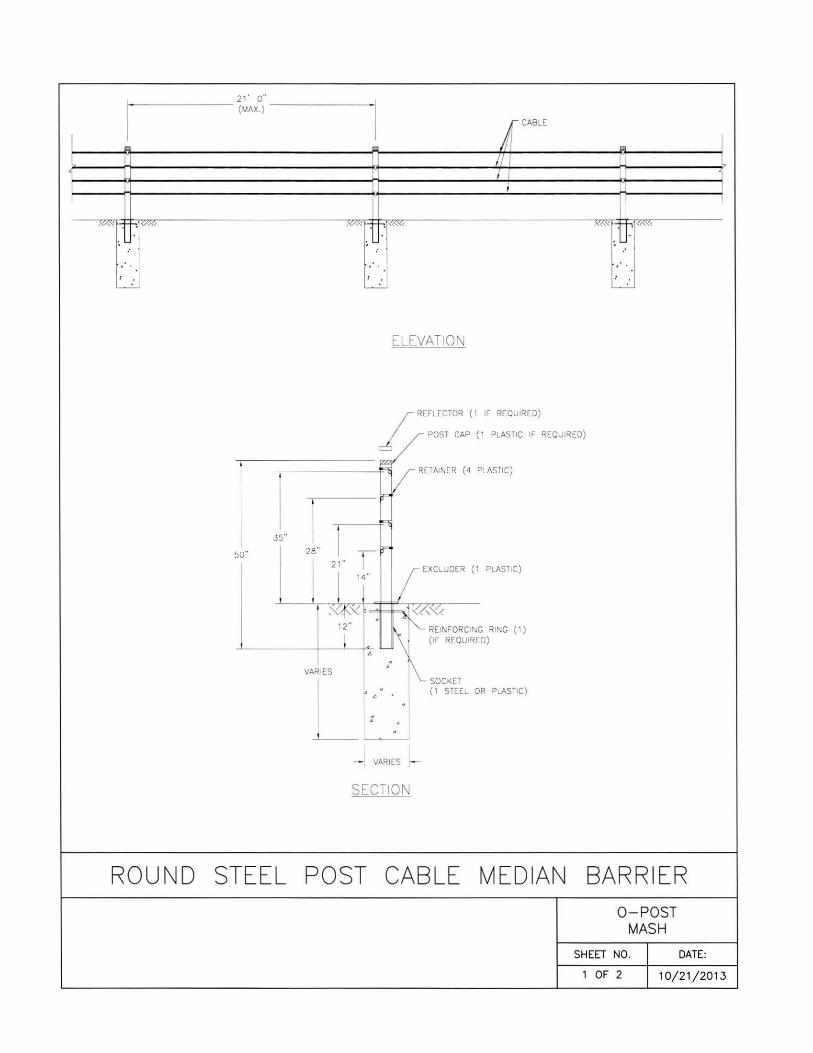
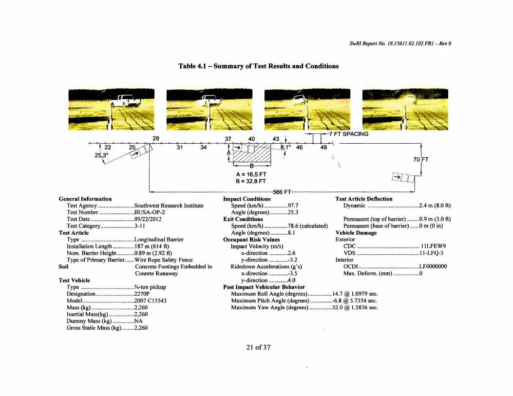
Table 41 - Summary ofTest Results and Conditions
28
22 25 253deg ~~10gt
General Information Test Agency Southwest Research Institute Test Number BUSA-OP-2 Test Date 05222012 Test Category 3-11
Test Article Type Longitudinal Barrier InsUillation Length 187 m (614 ft) Norn Barrier Height 089 m (292 ft) Type of Primary Barrier Wire Rope Safety Fence
Soil Concrete Footings Embedded in Conrete Runaway
Test Vehicle Type 31-ton pickup Designation 2270P Model 2007 Cl5543 Mass (kg) 2 260 Inertial Mass(kg) 2260 Dummy Mass (kg) NA Gross Static Mass (kg) 2 260
37 40 31 34 46 49
) 70FT ( gt
A= 165 FT
B= 328 FT bull FT middot-_-l middotmiddotlL middot J (
Impact Conditions Test Article Deflection Speed (kmlh) 977 Dynamic 2 4 m (80 ft) Angle (degrees) 25 3
Exit Coaditions Permanent (top of barrier) D9 m (30 ft) Speed (kmh) 786 (calculated) Permanent (base of barrier) 0 m (0 in) Angle (degrees) 81 Vehicle Damage
Occupant Risk Values Exterior Impact Velocity (mls) CDC 11 LFEW9
x-direction 2 6 VOS 11-LFQ-3 y-direction -32 Interior
Ridedown Accelerations (gs) OCDI LFOOOOOOO x-direction -35 Max Deform (mm) 0 y-direction 40
Post Impact Vehicular Behavior Maximum Roll Angle (degrces) 147 10979 sec Maximum Pitch Angle (degrees) -68 57354 sec Maximum Yaw Angle (degrees) 320 15836 sec
SwRI Report No 181561102102FRl -Rev 0
21 of37
Table 41 - Summary ofTest Results and Conditions
- -7 FT SPACING I
t (bull J _5 middot-middot 8 middot-middot I) bullbull V 37 40 ~ middot-middot ~ middotbull middot-middot
31 22 2410 -- middotmiddot~~ 341rcJ 108middot 43 bullJ middot
46 ~middot middotgt bull)
49 52 55 t58middot- + middot-_7 --middot middotr middot- i
A= 145 FT B =328 FT
192FT ~-~r General Information Impact CondiCions Test Article Deflection
Test Agency Southwest Research institute Speed (kmh) I 039 Dynamic 16 m (5 1 ft) Test Number BUSAmiddotOP-3 Angle (degrecs) 24 I Test Date 0512312012 Exit Conditions Permanent (top ofbarrier) 09 m (30 ft) Test Category middot-middot----middot------- 3-10 Speed (kmh) 69I (calculated) Permanent (base ofbarrier) Om (0 in)
Test Article Angle (degrees) 108 Vehicle Damage Type Longitudinal Barrier Occupant Risk Values Exterior Installation Lcngth 187 m (6 14 ft) Impact Velocity (mis) CDC I ILFEA9 Norn Barrier Height 089 m (292 ft) x-direction 38 VOS 11-LFQ-5 Type of Primary BarrierWire Rope Safety Fence y-direction -40 Interior
Soil Concrete Footings Embedded in Ridedown Accelerations (gs) OCDJ LFOOOOOOO Conrcte Runaway x-direction -78 Max Deform (mm) 91
Test Vehicle y-direction 89 Type car Post Impact Vehicular Behavior Designation 11 OOC Maximum Roll Angle (degrees) 83 60981 sec Model 2003 7 C 15543 Maximum Pitch Angle (degrees) -48 05220 sec Mass (kg) 1155 Maximum Yaw Angle (degrees) 910 63452 sec Inertial Mass(kg)1080 Dummy Mass (kg) 75 Gross Static Mass (kg)1155
SwRJ Report No 181561102103FRl - Rev 0
shy
22 of39
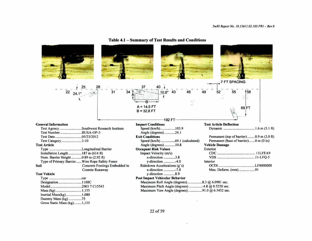
Table 41 - Summary ofTest Results and Conditions
- -7 FT SPACING I
t (bull J _5 middot-middot 8 middot-middot I) bullbull V 37 40 ~ middot-middot ~ middotbull middot-middot
31 22 2410 -- middotmiddot~~ 341rcJ 108middot 43 bullJ middot
46 ~middot middotgt bull)
49 52 55 t58middot- + middot-_7 --middot middotr middot- i
A= 145 FT B =328 FT
192FT ~-~r General Information Impact CondiCions Test Article Deflection
Test Agency Southwest Research institute Speed (kmh) I 039 Dynamic 16 m (5 1 ft) Test Number BUSAmiddotOP-3 Angle (degrecs) 24 I Test Date 0512312012 Exit Conditions Permanent (top ofbarrier) 09 m (30 ft) Test Category middot-middot----middot------- 3-10 Speed (kmh) 69I (calculated) Permanent (base ofbarrier) Om (0 in)
Test Article Angle (degrees) 108 Vehicle Damage Type Longitudinal Barrier Occupant Risk Values Exterior Installation Lcngth 187 m (6 14 ft) Impact Velocity (mis) CDC I ILFEA9 Norn Barrier Height 089 m (292 ft) x-direction 38 VOS 11-LFQ-5 Type of Primary BarrierWire Rope Safety Fence y-direction -40 Interior
Soil Concrete Footings Embedded in Ridedown Accelerations (gs) OCDJ LFOOOOOOO Conrcte Runaway x-direction -78 Max Deform (mm) 91
Test Vehicle y-direction 89 Type car Post Impact Vehicular Behavior Designation 11 OOC Maximum Roll Angle (degrees) 83 60981 sec Model 2003 7 C 15543 Maximum Pitch Angle (degrees) -48 05220 sec Mass (kg) 1155 Maximum Yaw Angle (degrees) 910 63452 sec Inertial Mass(kg)1080 Dummy Mass (kg) 75 Gross Static Mass (kg)1155
SwRJ Report No 181561102103FRl - Rev 0
shy
22 of39
Related Documents