(12) United States Patent (io) Patent No.: US 7,198,225 B2 Lisoski et al. (45) Date of Patent: Apr. 3,2007 (54) AIRCRAFT CONTROL SYSTEM 3,972,490 A * 8/1976 Zimmermann et al. .... 244/12.3 4,354,646 A 10/1982 Raymer ....................... 244/87 4,375,697 A 3/1983 Visher 455/13 4,415,133 A 11/1983 Phillips (75) Inventors: Derek L. Lisoski, Simi Valley, CA (US); Greg T. Kendall, Simi Valley, ......................... CA (US) (73) Assignee: Aerovironment, Inc., Monrovia, CA (US) ( * ) Notice: Subject to any disclaimer, the term of this patent is extended or adjusted under 35 U.S.C. 154(b) by 762 days. (21) Appl. No.: 10/310,415 (22) Filed: Dec. 5, 2002 (65) Prior Publication Data US 200310141409 A1 Jul. 31. 2003 Related U.S. Application Data (62) Division of application No. 091527,544, filed on Mar. 16, 2000, now abandoned. (51) Int. C1. (52) U.S. C1. ........................................................ 244/55 (58) Field of Classification Search .................. 244155, 244134 R, 173, 13, 2,47, 35 R, 31, 49,45 R B64D 2 7/00 (2006.01) See application file for complete search history. (56) References Cited U.S. PATENT DOCUMENTS 1,288,384 A 12/1918 Coakley 1,815,341 A * 7/1931 Zaharoff D137,938 S * 5/1944 Maycen 2,496,087 A 1/1950 Fleming 2,626,348 A 1/1953 Nobles 2,969,933 A 1/1961 Vogt 3,161,373 A 12/1964 Vogt 3,165,280 A * 1/1965 Lee 3,188,025 A * 6/1965 Moorehead 3,839,860 A * 10/1974 Martin 3,937,424 A 2/1976 Meier et al. (Continued) FOREIGN PATENT DOCUMENTS DE 1215 222 4/1966 (Continued) OTHER PUBLICATIONS Flittie, K. and Curtin, B., “Pathfinder Solar-Powered Aircraft Flight Performance,” AIAA Paper 98-4446, Aug. 1998, pp. 618-632. (Continued) Primary Examiner-Tien Dinh (57) ABSTRACT A solar rechargeable, long-duration, span-loaded flying wing, having no fuselage or rudder. Having a two-hundred foot wingspan that mounts photovoltaic cells on most all of the wing’s top surface, the aircraft uses only differential thrust of its eight propellers to turn, pitch and yaw. The wing is configured to deform under flight loads to position the propellers such that the control can be achieved. Each of five segments of the wing has one or more motors and photo- voltaic arrays, and produces its own lift independent of the other segments, to avoid loading them. Five two-sided photovoltaic arrays, in all, are mounted on the wing, and receive photovoltaic energy both incident on top of the wing, and which is incident also from below, through a bottom, transparent surface. 8 Claims, 28 Drawing Sheets 106 104 https://ntrs.nasa.gov/search.jsp?R=20080009492 2018-09-09T12:26:59+00:00Z

Welcome message from author
This document is posted to help you gain knowledge. Please leave a comment to let me know what you think about it! Share it to your friends and learn new things together.
Transcript
(12) United States Patent (io) Patent No.: US 7,198,225 B2 Lisoski et al. (45) Date of Patent: Apr. 3,2007
(54) AIRCRAFT CONTROL SYSTEM 3,972,490 A * 8/1976 Zimmermann et al. .... 244/12.3 4,354,646 A 10/1982 Raymer ....................... 244/87 4,375,697 A 3/1983 Visher 455/13 4,415,133 A 11/1983 Phillips
(75) Inventors: Derek L. Lisoski, Simi Valley, CA (US); Greg T. Kendall, Simi Valley,
.........................
CA (US)
(73) Assignee: Aerovironment, Inc., Monrovia, CA (US)
( * ) Notice: Subject to any disclaimer, the term of this patent is extended or adjusted under 35 U.S.C. 154(b) by 762 days.
(21) Appl. No.: 10/310,415
(22) Filed: Dec. 5, 2002
(65) Prior Publication Data
US 200310141409 A1 Jul. 31. 2003
Related U.S. Application Data
(62) Division of application No. 091527,544, filed on Mar. 16, 2000, now abandoned.
(51) Int. C1.
(52) U.S. C1. ........................................................ 244/55 (58) Field of Classification Search .................. 244155,
244134 R, 173, 13, 2,47, 35 R, 31, 49,45 R
B64D 2 7/00 (2006.01)
See application file for complete search history.
(56) References Cited
U.S. PATENT DOCUMENTS
1,288,384 A 12/1918 Coakley 1,815,341 A * 7/1931 Zaharoff D137,938 S * 5/1944 Maycen 2,496,087 A 1/1950 Fleming 2,626,348 A 1/1953 Nobles 2,969,933 A 1/1961 Vogt 3,161,373 A 12/1964 Vogt 3,165,280 A * 1/1965 Lee 3,188,025 A * 6/1965 Moorehead 3,839,860 A * 10/1974 Martin 3,937,424 A 2/1976 Meier et al.
(Continued)
FOREIGN PATENT DOCUMENTS
DE 1215 222 4/1966
(Continued)
OTHER PUBLICATIONS
Flittie, K. and Curtin, B., “Pathfinder Solar-Powered Aircraft Flight Performance,” AIAA Paper 98-4446, Aug. 1998, pp. 618-632.
(Continued)
Primary Examiner-Tien Dinh
(57) ABSTRACT
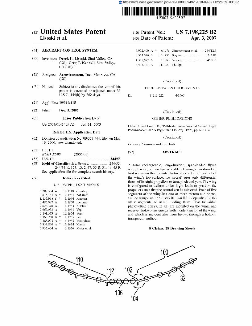
A solar rechargeable, long-duration, span-loaded flying wing, having no fuselage or rudder. Having a two-hundred foot wingspan that mounts photovoltaic cells on most all of the wing’s top surface, the aircraft uses only differential thrust of its eight propellers to turn, pitch and yaw. The wing is configured to deform under flight loads to position the propellers such that the control can be achieved. Each of five segments of the wing has one or more motors and photo- voltaic arrays, and produces its own lift independent of the other segments, to avoid loading them. Five two-sided photovoltaic arrays, in all, are mounted on the wing, and receive photovoltaic energy both incident on top of the wing, and which is incident also from below, through a bottom, transparent surface.
8 Claims, 28 Drawing Sheets
106 104
https://ntrs.nasa.gov/search.jsp?R=20080009492 2018-09-09T12:26:59+00:00Z
US 7,198,225 B2 Page 2
U.S. PATENT DOCUMENTS
4,492,353 A * 1/1985 Phillips 4,566,657 A 1/1986 Grow ....................... 244/90 A 4,568,043 A 2/1986 Schmittle ..................... 244/48 4,601,443 A 7/1986 Jones et al. 4,697,761 A 10/1987 Long 4,768,738 A 9/1988 Weinert 4,781,341 A 11/1988 Kasper ........................ 244/13 4,907,764 A 3/1990 Long 4,928,317 A 5/1990 Franchini .................... 455/601 4,958,289 A * 9/1990 Sum et al. 5,078,338 A * 1/1992 O’Neill et al. 5,106,035 A 4/1992 Langford, I11 5,131,605 A * 7/1992 Kress 5,135,185 A * 8/1992 Adamson et al. 5,356,094 A 10/1994 Sylvain 5,374,010 A * 12/1994 Stone et al. 5,379,969 A 1/1995 Marx et al. 5,465,170 A 11/1995 Arimoto ..................... 359/159 5,518,205 A 5/1996 Wurst et al. 5,531,402 A * 7/1996 Dah1 ........................ 244/75 R 5,652,750 A 7/1997 Dent et al. .................. 370/326 5,678,783 A 10/1997 Wong 5,710,652 A 1/1998 Bloom et al. ............... 359/152 5,808,472 A 9/1998 Hayes ........................ 324/671 5,810,284 A 9/1998 Hibbs et al. .................. 244/13 5,839,699 A 11/1998 Bliesner 5,842,666 A * 12/1998 Gerhardt et al. 6,070,833 A 6/2000 Burke et al. 6,076,766 A 6/2000 Gmensfelder
DE DE FR FR GB JP JP wo wo wo wo wo wo
6,126,111 A * 10/2000 Burcham et al. 6,364,251 B1 4/2002 Yim
FOREIGN PATENT DOCUMENTS
43 OS 758 A1 9/1994 296 16 989 U1 1/1997
1446609 9/1965 2 721 458 12/1995 2 082 995 A 3/1982 04325395 11/1992 11-348894 12/1999
WO 95/04407 2/1995 WO 95/12237 5/1995 WO 97/33790 9/1997 WO 98/35506 8/1998 WO 99/13598 3/1999 WO 99/23769 5/1999
OTHER PUBLICATIONS
Djuknic, G.M., Freidenfelds, J., and Okunev, Y., “Establishing Wireless Communications Services via High-Altitude Aeronautical Platforms: A Concept Whose Time Has Come?,” IEEE Communi- cations Magazine, Sep. 1997, pp. 128-135. “Lockheed Studies Solar-Powered Surveillance Aircraft,” Aviation Week and Space Technology, Dec. 6, 1982, p. 120. Aronson, Robert B., “Solar-Powered Planes,” Machine Design, Feb. 7, 1985, vol. 57, p. 32.
* cited by examiner
U.S. Patent Apr. 3,2007 Sheet 1 of 28 US 7,198,225 B2
U.S. Patent Apr. 3,2007 Sheet 2 of 28 US 7,198,225 B2
U.S. Patent Apr. 3,2007 Sheet 3 of 28 US 7,198,225 B2
U.S. Patent Apr. 3,2007 Sheet 4 of 28 US 7,198,225 B2

U.S. Patent Apr. 3,2007 Sheet 5 of 28 US 7,198,225 B2
U.S. Patent Apr. 3,2007 Sheet 6 of 28 US 7,198,225 B2
13 3" I L
FIG. 6A
104
FIG. 6B
FIG. 6C
FIG. 6D
U.S. Patent Apr. 3,2007 Sheet 7 of 28 US 7,198,225 B2
100 \
FIG. 7A

U.S. Patent Apr. 3,2007 Sheet 8 of 28 US 7,198,225 B2
i \ ’

U.S. Patent Apr. 3,2007 Sheet 9 of 28 US 7,198,225 B2

U.S. Patent Apr. 3,2007 Sheet 10 of 28 US 7,198,225 B2
U.S. Patent Apr. 3,2007 Sheet 11 of 28
U
I J
d
US 7,198,225 B2
a Ir
U.S. Patent Apr. 3,2007 Sheet 12 of 28 US 7,198,225 B2
0
I
L L
3
i t
1 t
t
+ I 1 I
i I
1
U.S. Patent Apr. 3,2007 Sheet 13 of 28 US 7,198,225 B2

U.S. Patent Apr. 3,2007 Sheet 14 of 28 US 7,198,225 B2
FIG. I 1
U.S. Patent Apr. 3,2007 Sheet 15 of 28 US 7,198,225 B2
FIG, 12A
FIG. 12B
U.S. Patent Apr. 3,2007 Sheet 16 of 28 US 7,198,225 B2
U.S. Patent Apr. 3,2007 Sheet 17 of 28
I I I
I I I
I I
4-g- I
N
US 7,198,225 B2
I I

U.S. Patent Apr. 3,2007 Sheet 18 of 28 US 7,198,225 B2
U.S. Patent Apr. 3,2007 Sheet 19 of 28 US 7,198,225 B2
I
ttttttttt - H o%L
, ttttttttt
r
W
3 to t-
> z
U.S. Patent Apr. 3,2007 Sheet 20 of 28 US 7,198,225 B2
@TELEPHONE SWITCH HUB f~ SATELLITE EARTH STATION 6 GROUND-TO-AIR PHONE EARTH STATION
- TELEPHONE LINE _--- INTERNET
-RADIO LINK
FIG. 15

U.S. Patent Apr. 3,2007 Sheet 21 of 28 US 7,198,225 B2
R 322
i 302
\ 300
FIG. 16A
U.S. Patent Apr. 3,2007 Sheet 22 of 28 US 7,198,225 B2
U.S. Patent Apr. 3,2007 Sheet 23 of 28 US 7,198,225 B2

w h) 0 0 4
U.S. Patent Apr. 3,2007 Sheet 25 of 28 US 7,198,225 B2

FIG. 17A
w h) 0 0 4
U.S. Patent Apr. 3,2007 Sheet 27 of 28 US 7,198,225 B2
5i2
CONNECTION TO OR CPE HOUSE DATA OR ~ P A C S ANTENNA
TELEPHONE WIRING 524 FOR CORDLESS PHONE MODE
FIG. 17B
U.S. Patent Apr. 3,2007 Sheet 28 of 28 US 7,198,225 B2
WIRED CONNECTION TO
TELEPHONE WIRING 534 IN-HOUSE DATA OR
FIXED SUBSCRIBER PACS ANTENNA
TATION/ FOR CORDLESS ‘-PHONE MODE
AND TO GET SIGNAL FROM BASE STATION
FIG. 17C
US 7,198,225 B2 1
AIRCRAFT CONTROL SYSTEM
The present invention relates to aircraft. More particu- larly, the present invention relates to aircraft having unique controls, and related uses thereof. The present application is a divisional application of U.S. patent application Ser. No. 091527,544 filed Mar. 16, 2000 now abandoned, which is incorporated herein by reference for all purposes.
This invention was made with government support under ERAST JSRA Contract NCC-04004 awarded by NASA. The United States Government has certain rights in the invention.
BACKGROUND
Aircraft are used in a wide variety of applications, includ- ing travel, transportation, fire fighting, surveillance and combat. Various aircraft have been designed to fill the wide array of functional roles defined by these applications. Included among these aircraft are balloons, dirigibles, tra- ditional fixed wing aircraft, flying wings and helicopters.
One functional role that a few aircraft have been designed to fill is that of a high altitude platform. Operating from high, suborbital altitudes, such aircraft can monitor weather pat- terns, conduct atmospheric research and surveil a wide variety of subjects. Most of these remarkable aircraft have limited flight duration due to fuel limitations. However, a number of aircraft have been proposed that are solar pow- ered, and that can sustain continuous flight for as long as sunlight is available, or even longer.
Three such aircraft that have been constructed are the well-known Pathfinder, Centurion and Helios aircraft, which have set numerous flight records. The basic design under- lying these aircraft is discussed at length in U.S. Pat. No. 5,810,284, which is directed toward an unswept flying wing aircraft having a very high aspect ratio and a relatively constant chord and airfoil. While these aircraft are quite noteworthy for their long term flight potential, they do have limits in their available power and payload.
Such aircraft are designed as flying wings that include a number of self-sufficient wing sections, each having one or more electric motors that are driven by power generated in solar cells mounted in that section, and each generating enough lift to support its own weight. To minimize weight, the aircraft structure is highly flexible, and is designed to withstand only relatively small torsional loads along its lateral axis. The aircraft’s wing has little or no dihedral while on the ground. However, due to the high flexibility, the large aspect ratio and the constant chord, in-flight wing loads tend to cause the wing to develop a substantial dihedral angle at the wingtips.
To minimize the torsional loads, the aircraft wing includes elevators along a substantial portion of its trailing edge (i.e., the trailing edge of the flying wing). The aircraft does not include a rudder or ailerons, and the elevators are not designed as elevons (i.e., they cannot move in contrary directions near opposite wingtips). Instead, the aircraft turns (and otherwise controls yaw) by using variable thrust applied across the wingspan through the application of different power levels to different motors. Roll is passively controlled by the dihedral of the wing, which is developed in flight. Sideslip is also passively controlled, both by the dihedral of the wing, and by fins that extend down from a number of wing segments in a direction normal to plane of the wing at the fin’s span-wise location.
Long duration high altitude platforms that operate at suborbital altitudes, such as the Pathfinder and Centurion
5
10
15
20
25
30
35
40
45
50
55
60
6 5
2 aircraft, have been suggested for use in a variety of func- tions. As one example, a high altitude platform equipped with microwave communications equipment could provide communication relay services between remote areas. In another example, high altitude platforms could measure and study winds, storms or pollutants in the atmosphere. Simi- larly, governments could use these aircraft to monitor troop movements or narcotics production. Other types of aircraft are not optimally suited to these tasks, because they are limited by the amount of combustible fuels that they use, which are heavy, expensive and are consumed very quickly. Typically, these other types of aircraft cannot remain over their desired location for any significant length of time, and hence, are of limited utility in performing these tasks.
One way around these operational limitations is to use satellites as high altitude platforms. However, satellites are expensive to launch, and typically remain in a permanent, fixed orbit. Some satellites can change their orbit to a limited degree; however, this is done only with great difficulty and expense, and there is a fuel limit to how many orbital changes a satellite may make. For example, if it is desired to measure and study a hurricane that originates in Africa and travels toward the Gulf coast of the United States, satellites cannot, practically-speaking, be asked to follow and track such a storm.
The use of satellites is also disadvantageous for many types of measurement and surveillance as well, because satellites orbit outside the Earth‘s atmosphere. That is to say, satellites as a practical matter cannot use many tools that optimally require contact with the atmosphere. Photographic images taken by a satellite are also sometimes less than optimal, since the target is usually a great distance from the satellite. Finally, satellites are not easily brought back to Earth and retrieved, e.g., for servicing, and so are typically used only for one very expensive, special purpose task.
Given the broad range of functions that a long-duration, suborbital platform has the potential to perform, it is desir- able to design such platforms to be capable of handling larger payloads and power demands. The platforms could be variations of existing platforms, such as the Pathfinder and Centurion aircraft, or they could be newly designed, high altitude platforms.
Likewise, given a high altitude platform with expanded payload and power capabilities, it is desirable to find new uses for the platform. Such new uses can increase demand for the aircraft, and thereby cause increased production and lower production costs. Naturally, new uses also have the potential for new advantages for the public.
In sum, there exists a definite need for a multi-purpose aircraft that can remain airborne for long durations without the need to re-fuel. Preferably, such an aircraft should be able to operate up to very high, suborbital altitudes. Impor- tantly, it is desirable for such an aircraft to have the capa- bility for larger payloads andor power supply requirements. Furthermore, there exists a need for such an aircraft to be inexpensive to build and operate and, furthermore, pollu- tion-free. Also, a definite need exists for such an aircraft to be able to perform surveillance, testing and measurement functions while being steerable, mobile, and able to perform varying missions of extended duration. Finally, with the availability of the hardware of the present invention, it should be noted that a broad variety of communications needs exist that such a high altitude platform can fill. Various embodiments of the present invention can meet some or all of these needs, and provide further, related advantages.
US 7,198,225 B2 3
SUMMARY OF THE INVENTION
The present invention solves the needs mentioned above by providing a solar powered aircraft that is inexpensive to produce and can remain aloft almost indefinitely, that is, at least until its parts wear out. Thus, the present invention provides an aircraft that is perfectly suited to many appli- cations requiring a high altitude platform. For example, the aircraft could be guided to follow a hurricane, and using equipment on board, study how such storms originate and develop. Alternatively, the present aircraft provides a sub- orbital platform that can be used to convert radio wave signals from a ground station to optical signals directed to a satellite, or other spacecraft, that is above suborbital alti- tudes. Likewise, the aircraft can be coupled with a large number of ground stations to create broadband andor wire- less networks. However, the present aircraft is not only far less expensive to produce than satellites; it is retrievable and may be reused for the same or different tasks. By using solar power, the present aircraft is completely pollution free, and thus, provides potent promise for displacing the use of combustion-powered aircraft in many of these applications.
The aircraft of the invention typically includes a wing, including a first wing portion and a second wing portion, with a solar cell array mounted on the wing. The aircraft preferably features a hinge mechanism that is connected to the first wing portion, and is configured to allow a pivoting of the first wing portion relative to the second wing portion. Each wing portion is preferably configured to generate enough lift to carry its own weight while the aircraft is in flight, and the pivoting is preferably limited to a value that generally allows each wing portion to continue to generate enough lift to carry its own weight. The aircraft can also feature a hinge actuator configured to control the hinge mechanism such that the dihedral of the first and second wing portions can be altered with respect to each other during flight. Finally, a control system is preferably con- nected to the hinge actuator, causing it to actuate the hinge such that the dihedral is greater during time periods when a greater dihedral will increase the power generated by the solar cells.
Preferably, the aircraft is a flying wing aircraft including a plurality of sequentially connected, unswept, wing seg- ments (most preferably five or more wing segments). Also, preferably the hinge actuator includes a mass actuator con- figured to translate the center of gravity of a mass carried by the wing, and wherein the wing and the mass are configured such that the location of the center of gravity of the mass can drive the rotation of the hinge mechanism when the wing is in flight conditions. To drive the rotation, the mass’s chang- ing center of gravity location may deform the wing, creating aerodynamic forces.
The aircraft may also feature a laterally extending wing configured to have dihedral during flight, and a plurality of motors mounted on the wing. The wing’s dihedral is con- figured to cause at least one motor to produce thrust along a line passing above the aircraft’s center of drag, and at least one motor to produce thrust along a line passing below the aircraft’s center of drag when the aircraft is in flight condi- tions, the motors causing downward and upward pitching moments, respectively. The aircraft also includes a control system connected to the throttle of each motor, and it controls at least one of the throttles to control the pitch of the aircraft. A remote pilot can control the aircraft through the use of redundant combinations of existing communications networks.
4 Other features and advantages of the invention will
become apparent from the following detailed description of the preferred embodiments, taken in conjunction with the accompanying drawings, which illustrate, by way of
5 example, the principles of the invention. The detailed description of particular preferred embodiments, as set out below to enable one to build and use an embodiment of the invention, are not intended to limit the enumerated claims, but rather, they are intended to serve as particular examples
10 of the claimed invention.
BRIEF DESCRIPTION OF THE DRAWINGS
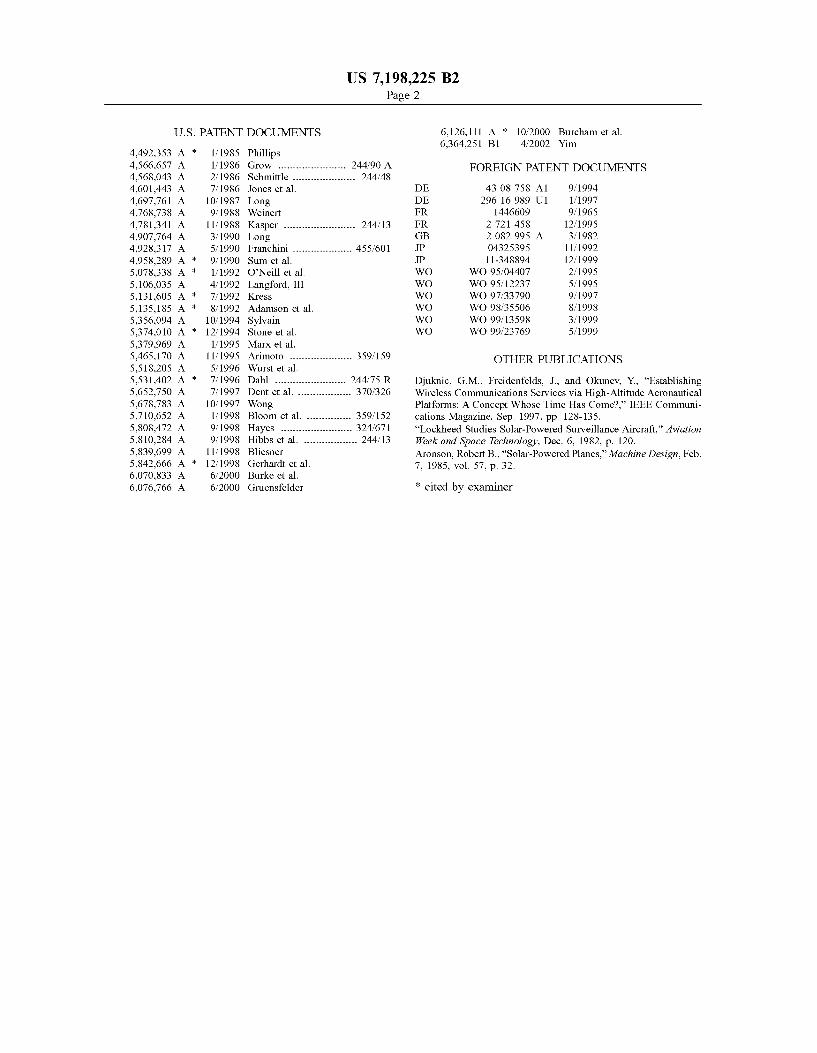
FIG. 1 is an elevational view of a preferred embodiment 15 of an aircraft embodying the invention, in a zero stress
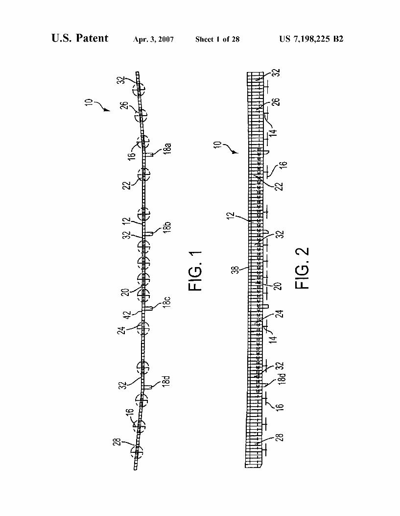
FIG. 2 is a plan view of the aircraft depicted in FIG. 1. FIG. 3 is a perspective view of the aircraft depicted in
FIG. 1, in a flexed position typical of loading under flight
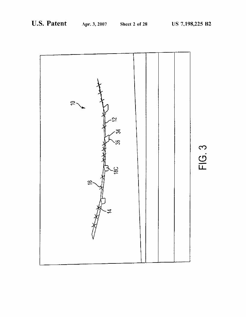
FIG. 4 is a perspective view of the aircraft depicted in FIG. 1, in a flexed position typical of loading while the aircraft is at rest on the ground.
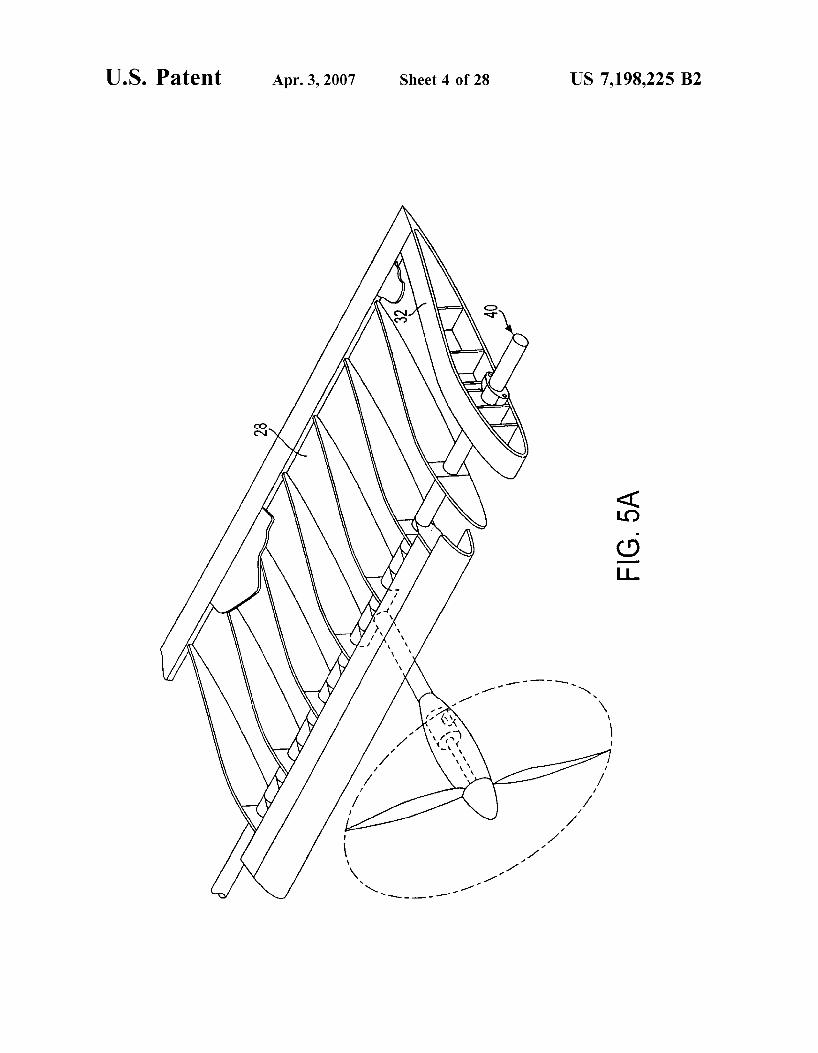
FIG. 5A is a perspective, cutaway view showing the 25 construction of one segment of the wing of the aircraft
depicted in of FIG. 1. FIG. 5B is a cut-away plan view of the wing segment
depicted in FIG. 5A, with a regenerative fuel cell structured within the wing.
FIG. 5C is a cross-sectional side view of the segment of FIG. 5A, taken along lines C< of FIG. 5B.
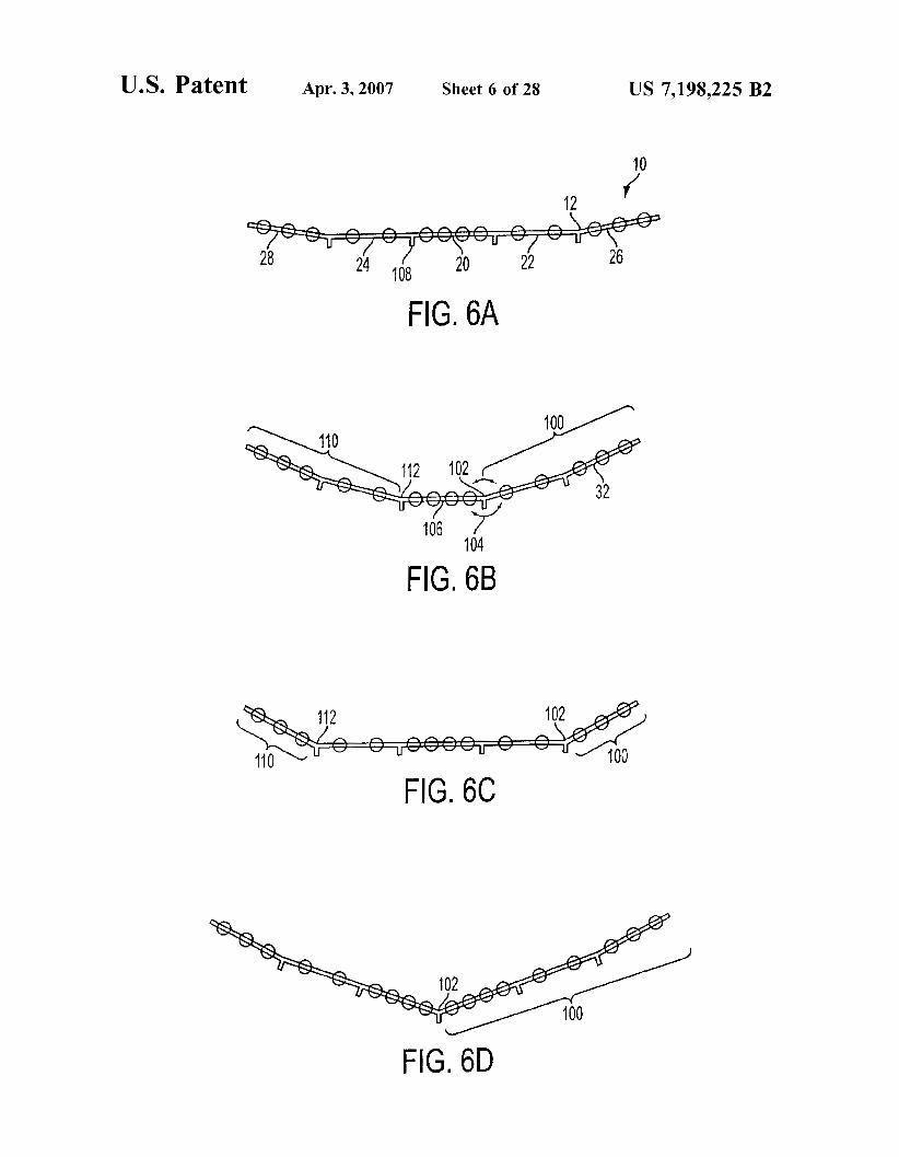
FIG. 6A is a front elevational view of the aircraft depicted in FIG. 1, having five wing segments, the aircraft being
position.
20 conditions.
30
depicted in a position typical of loading while the aircraft is
FIG. 6B is a front elevational view of the aircraft depicted in FIG. 6A, having two hinge actuators that have rotated to allow two wing segments on either side of the plane to increase in dihedral.
FIG. 6C is a front elevational view of the aircraft depicted in FIG. 6A, having two hinge actuators that have rotated to allow one wing segment on either side of the plane to increase in dihedral.
FIG. 6D is a front elevational view of the aircraft depicted in FIG. 6A, having six wing segments rather than five, and having one hinge actuator that has rotated to allow three wing segments on either side of the plane to increase in dihedral.
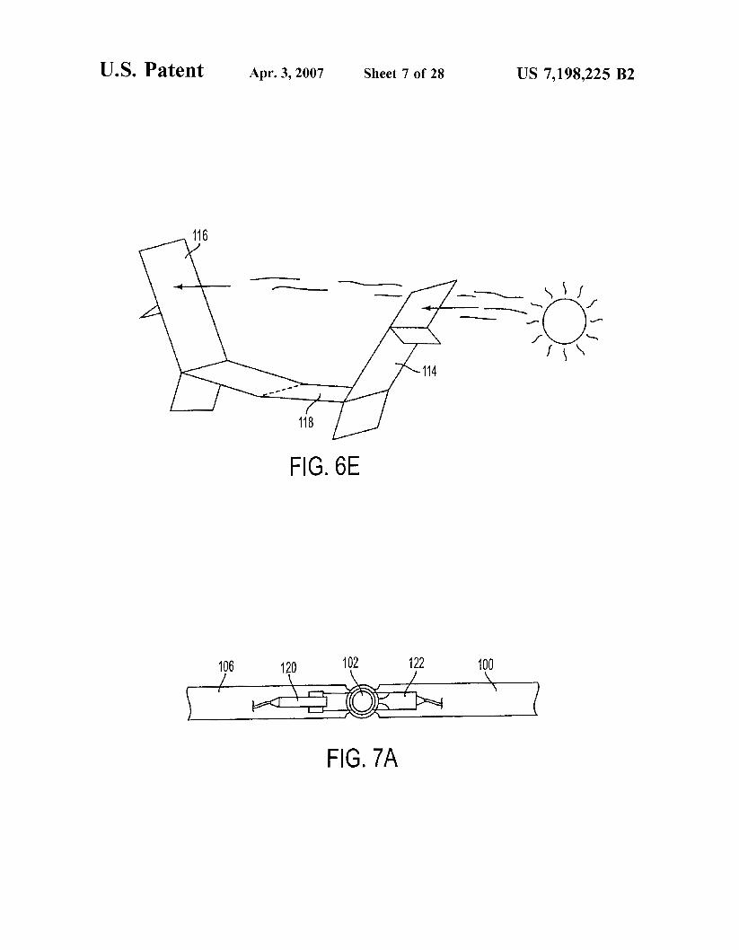
FIG. 6E is a perspective view of the aircraft depicted in FIG. 6B and the sun, wherein the sun is low on the horizon and off one wingtip of the aircraft.
FIG. 6F is a perspective view of the aircraft depicted in FIG. 6A, having four wing segments rather than five, having
55 a varied vertical fin configuration, and having three hinge actuators rotated to allow the four wing segments to form a “W’ shape.
FIG. 7A is an elevational, cross-sectional view of a hinge in the aircraft depicted in FIG. 6B.
FIG. 7B is an elevational, cross-sectional view of a first variation of the hinge depicted in FIG. 7A.
FIG. 7C is an elevational, cross-sectional view of a second variation of the hinge depicted in FIG. 7A.
FIG. 7D is an elevational, cross-sectional view of a third 65 variation of the hinge depicted in FIG. 7A, in a flexed
FIG. 7E is a plan view of the hinge depicted in FIG. 7D.
35 in flight.
40
45 .
50
6o
position, and including an attachment for a fin.

US 7,198,225 B2 5
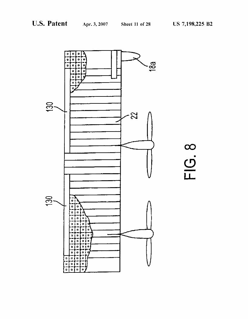
FIG. 8 is a top, cut-away view of one section of the wing from a first variation of the aircraft depicted in FIG. 6B, showing a hinge actuator that includes ailerons.
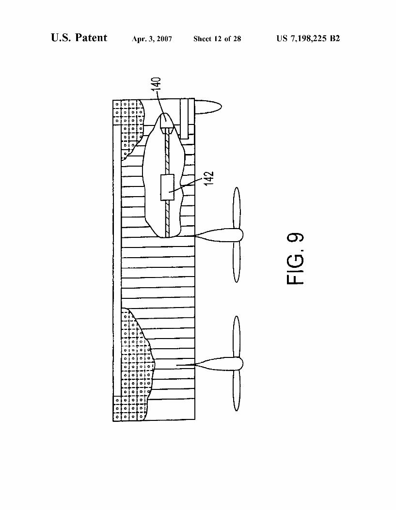
FIG. 9 is a top, cut-away view of one section of the wing from a second variation of the aircraft depicted in FIG. 6B, showing a hinge actuator that includes a laterally movable mass.
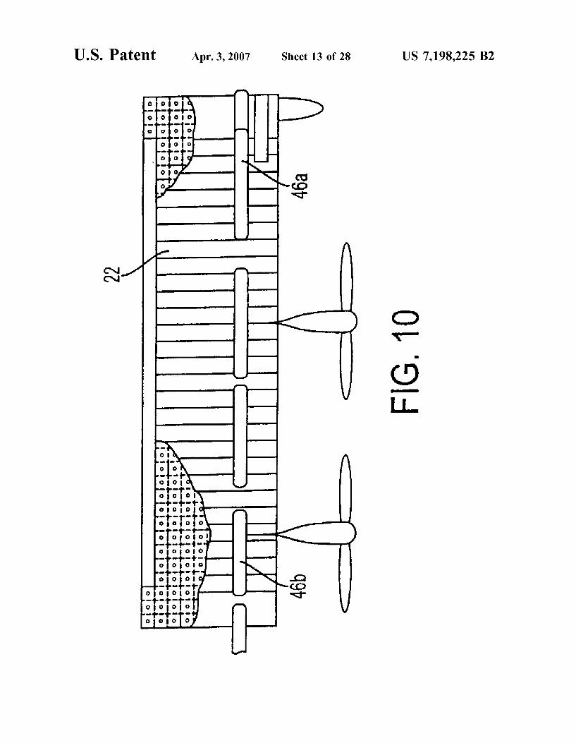
FIG. 10 is a top, cut-away view of one section of the wing from an alternative second variation of the aircraft depicted in FIG. 6B, showing tanks used for lateral mass movement.
FIG. 11 is a side cross-sectional view of a third variation of the aircraft depicted in FIG. 5B, showing a hinge actuator that includes a mass moveable in the fore-and-aft direction.
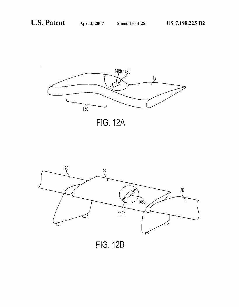
FIG. 12A is a perspective cross-sectional view of an alternate third variation of the aircraft depicted in FIG. 6B, showing a hinge actuator that includes a mass moveable in the fore-and-aft direction, and showing a local area wing deflection resulting from the moving mass.
FIG. 12B is a perspective cross-sectional view of another alternative third variation of the aircraft depicted in FIG. 6B, showing a hinge actuator that includes a mass moveable in the fore-and-aft directions, and showing a wing segment deflecting from the moving mass.
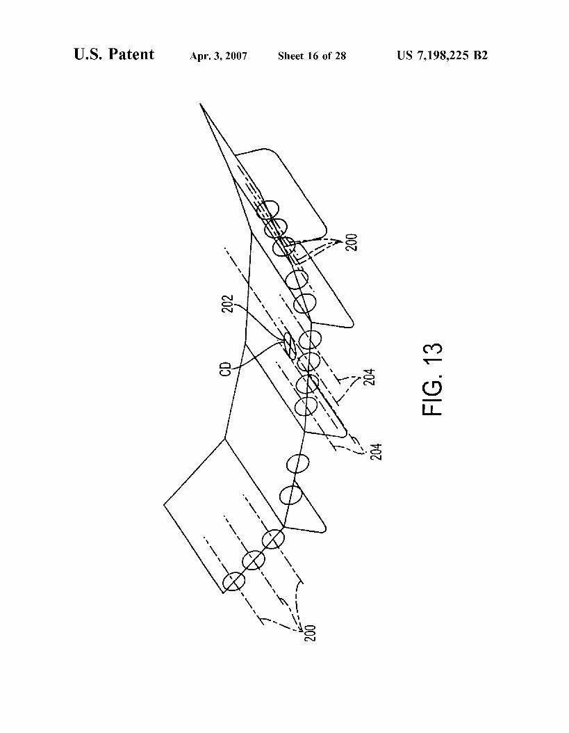
FIG. 13 is a perspective view of a variation of the aircraft depicted in FIG. 1, in a position typical of loading while the aircraft is in flight, configured such that some motors are located above the center of drag, and some motors are located below the center of drag.
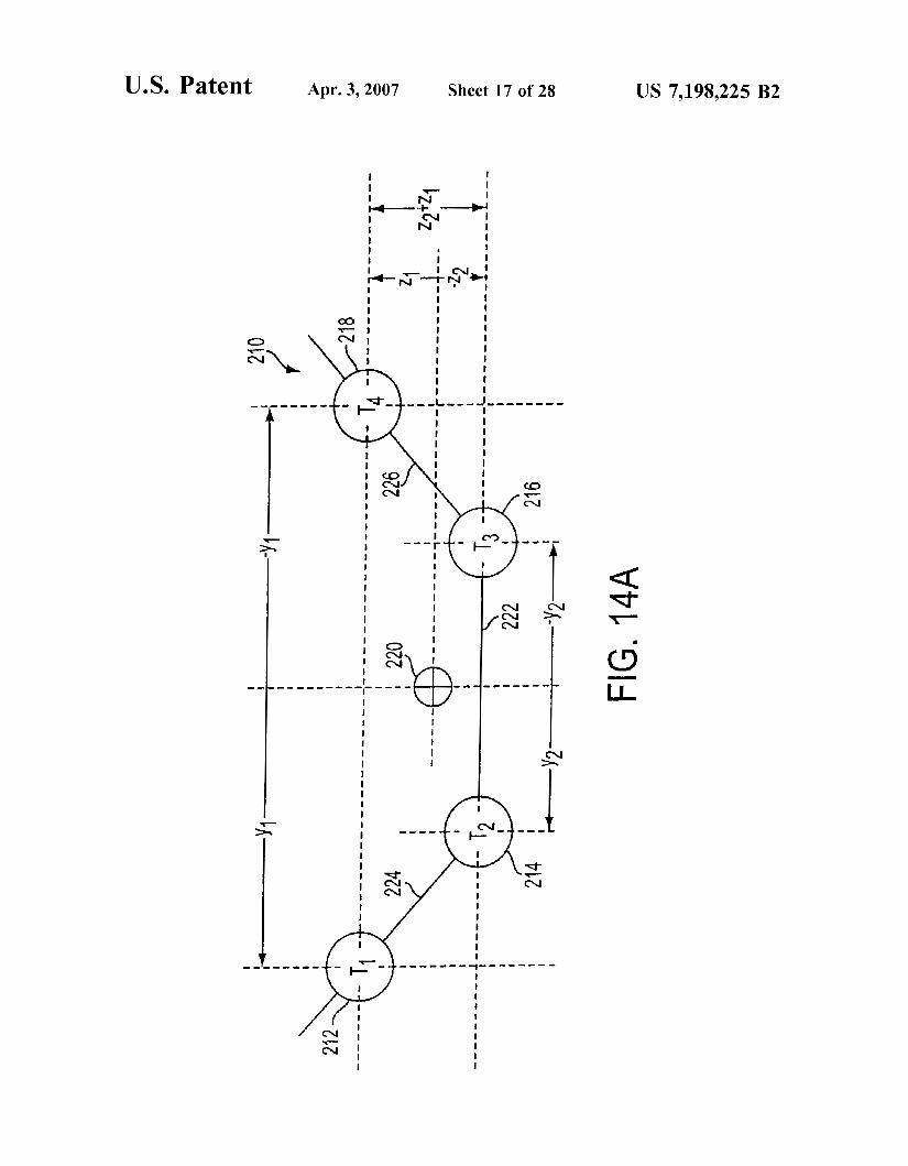
FIG. 14A is an illustration of a first idealized flexible aircraft having three axis flight control, according to the present invention.
FIG. 14B is an illustration of a second, and more general, idealized flexible aircraft having three axis flight control, according to the present invention.
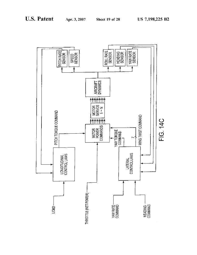
FIG. 14C is a block diagram of a control system imple- menting control laws form the aircraft illustrated in FIG. 14B.
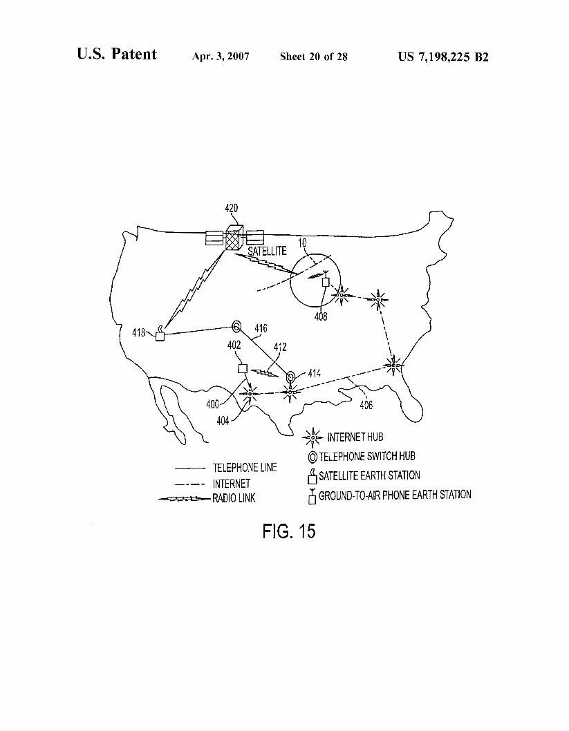
FIG. 15 is an illustrative view of an embodiment of an aircraft control communications system for the aircraft depicted in FIG. 1.
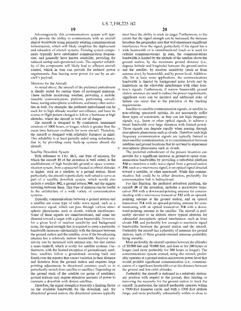
FIG. 16A is an illustrative view of the aircraft depicted in FIG. 1, acting as a high altitude platform in a communica- tions system, to pass signals between a ground station using radio wave signals and a satellite using optical signals. FIG. 16A further depicts a hand-off of communications from one satellite to a second satellite.
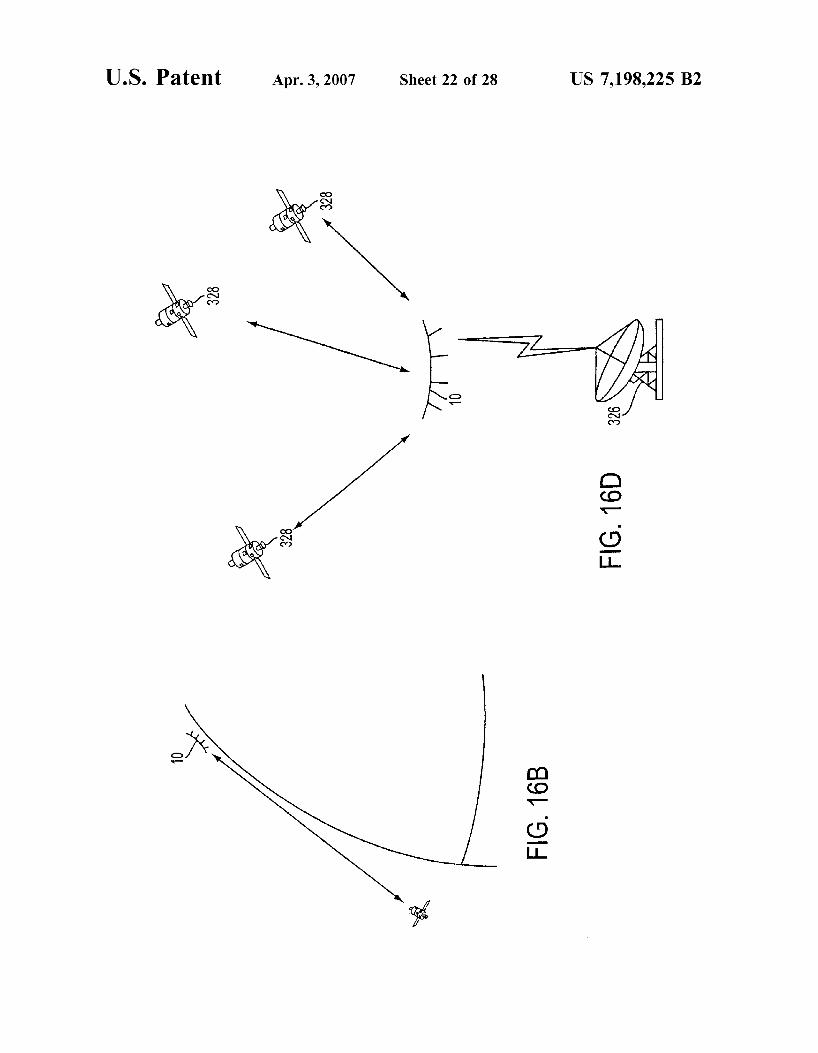
FIG. 16B is an illustrative view of the communications system of FIG. 16A, where the satellite is at a significantly different latitude than the ground station.
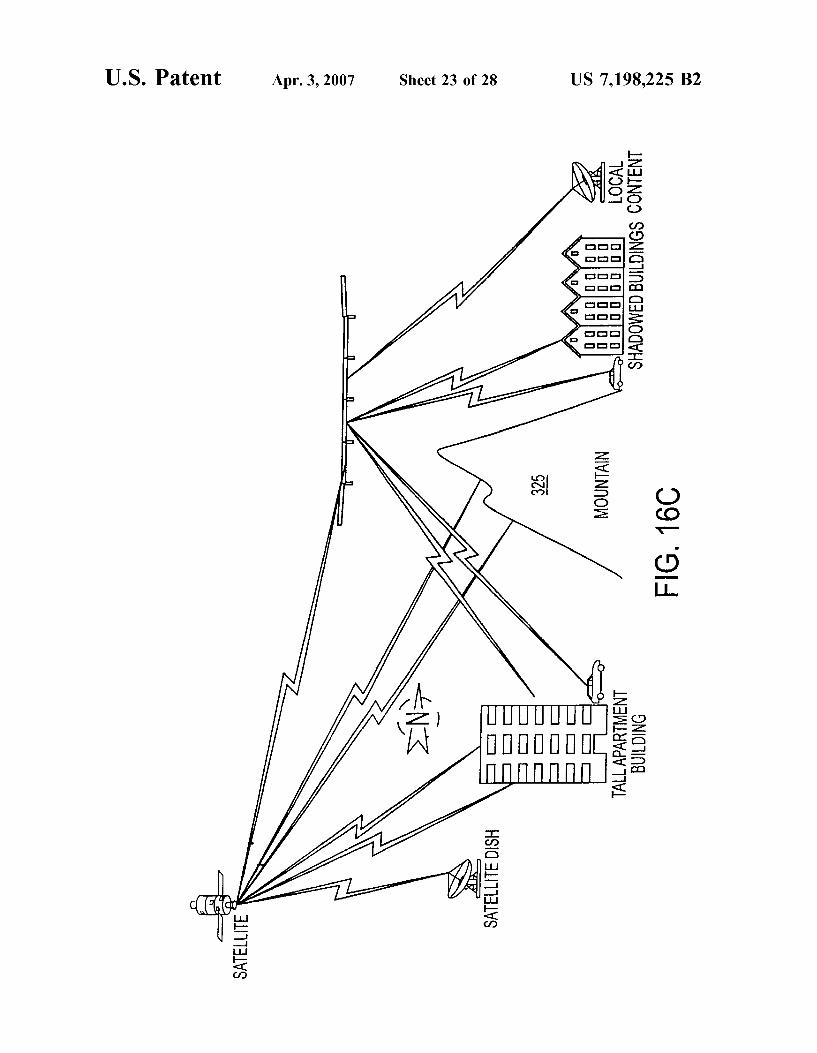
FIG. 16C is an illustrative view of the communications system of FIG. 16A, where the aircraft communicates with multiple ground stations and the satellite is obstructed from one or more of the ground stations by a mountain.
FIG. 16D is an illustrative view of the communications system of FIG. 16A, where the aircraft simultaneously communicates with three different satellites.
FIG. 16E is an illustrative view of the communications system of FIG. 16A, where the satellite simultaneously communicates directly with two aircraft and a ground sta- tion.
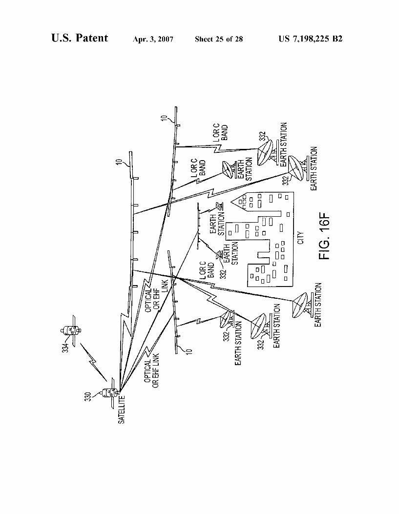
FIG. 16F is an illustrative view of the communications system of FIG. 16A, where one satellite communicates with multiple aircraft, each of which serves as a base station for communicating with multiple ground stations.
FIG. 17A is an illustrative view of the aircraft depicted in FIG. 1, acting as a high altitude, suborbital platform base
6 station in a broadband, wireless local loop or other commu- nications system with subscriber base stations and sub- scriber remote stations.
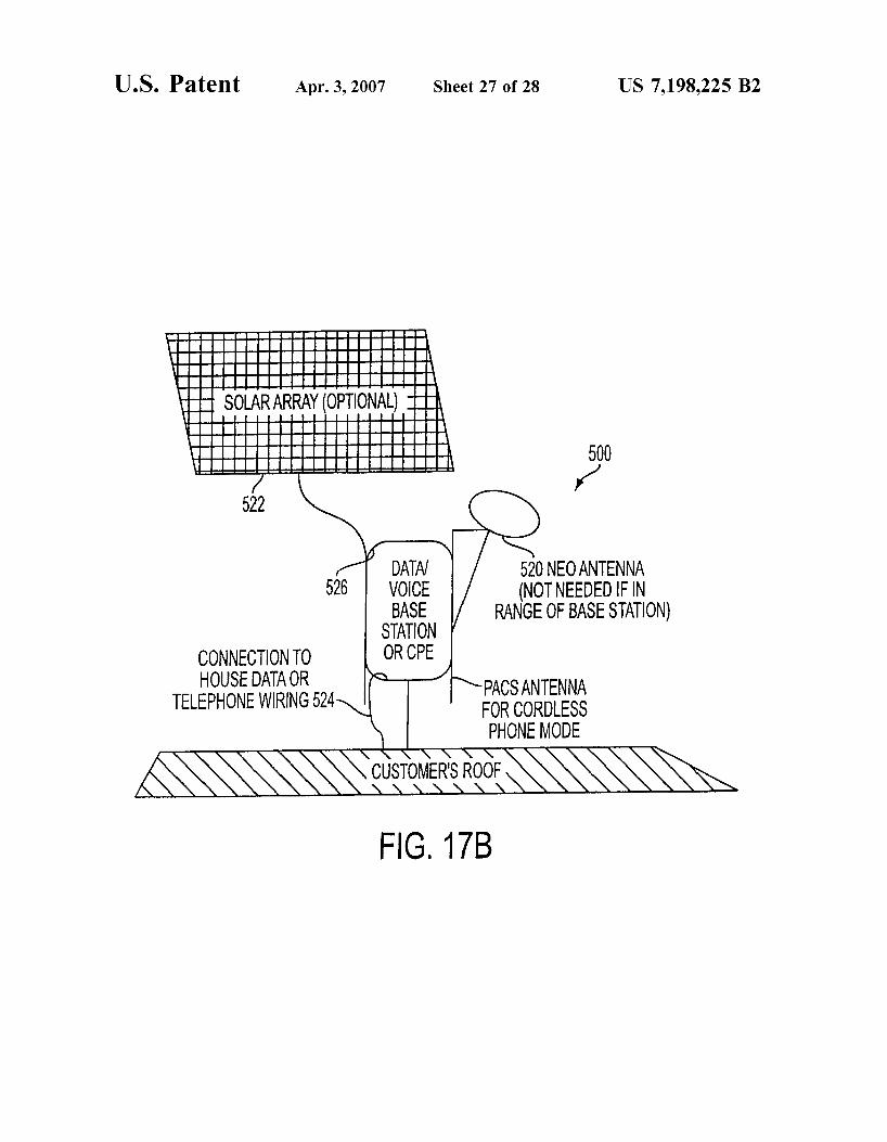
FIG. 17B is a view of a subscriber base station for use 5 with the communications system illustrated in FIG. 17A.
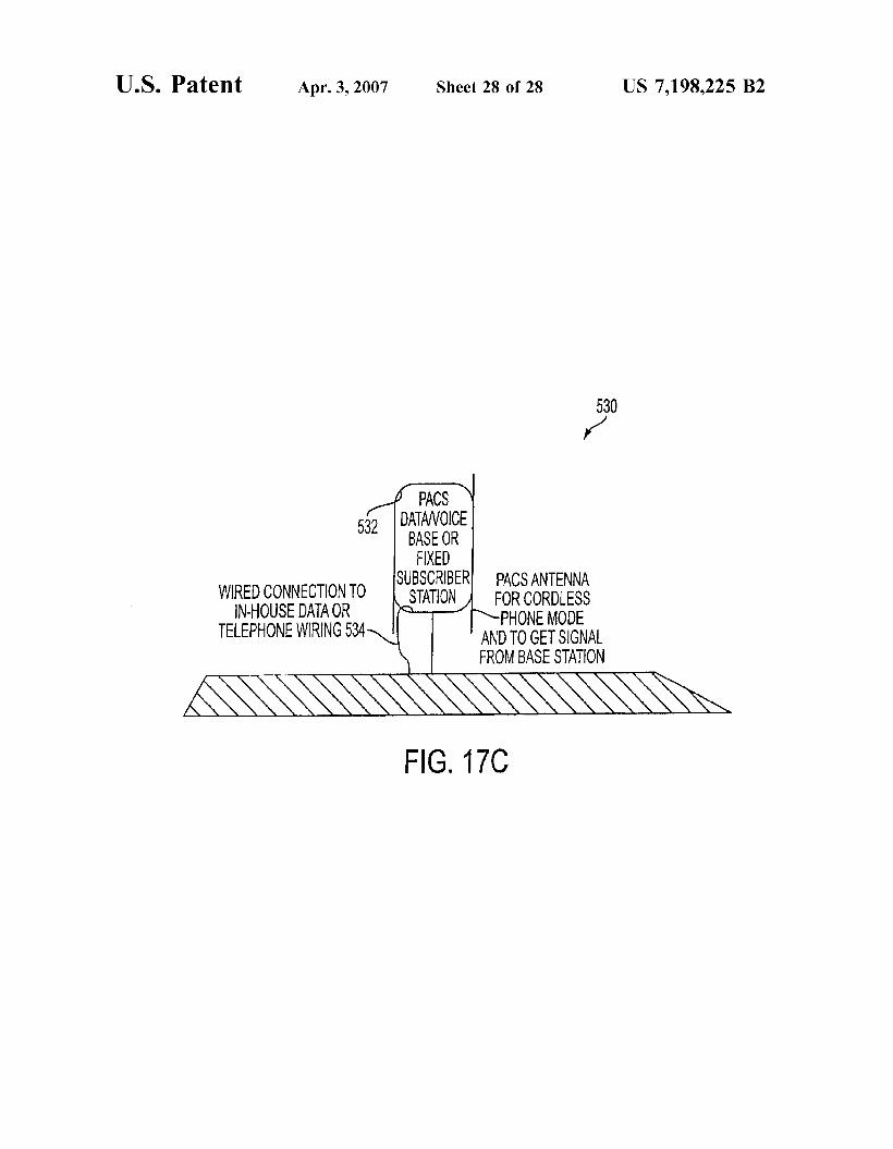
FIG. 17C is a view of a subscriber remote station for use with the communications system illustrated in FIG. 17A.
DETAILED DESCRIPTION OF THE 10 PREFERRED EMBODIMENTS
The invention summarized above and defined by the enumerated claims may be better understood by referring to the following detailed description, which should be read in
15 conjunction with the accompanying drawings. This detailed description of a particular preferred embodiment, set out below to enable one to build and use one particular imple- mentation of the invention, is not intended to limit the enumerated claims, but rather it is intended to serve as a
Introduction to the Preferred Aircraft In accordance with the present invention, the preferred
embodiment of an aircraft of the present invention is of a 25 design similar to that of the Pathfinder and Centurion
aircraft, as mentioned above in the Background section. While the preferred aircraft embodiment’s design, and varia- tions of it, are described below, further details useful for the practicing of this invention are provided in U.S. Pat. No.
3o 5,810,284, which is incorporated herein by reference. Nev- ertheless, it is to be understood that designs for other embodiments of the invention can include apparatuses that differ substantially from the described aircraft.
The preferred embodiment is a solar-powered, flying 35 wing with fuel cells to store energy for continuous day and
night flight. The aircraft includes a plurality of laterally connected, wing segments that each support their own weight in flight so as to minimize inter-segment loads, and thereby minimize required load-bearing structure. In most
4o variations of the preferred embodiment, the segments have elevators, but not ailerons or rudders, further limiting inter- segment loads. While these features are preferred, they are not required in all possible embodiments of the invention.
With reference to FIGS. 1-3, the preferred embodiment is 45 a flying wing aircraft 10, i.e., it has no fuselage or empen-
nage. Instead, it consists of an unswept wing 12, having a substantially consistent airfoil shape and size along the wingspan. Preferably, six, eight or fourteen motors 14 are situated at various locations along the wingspan, each motor
50 driving a single propeller 16 to create thrust. Preferably, two, four or five vertical fins 18a-l8d, or pods, extend down from the wing, with landing gear at their lower ends.
The aircraft 10 is longitudinally divided into preferably five or six, modular segments sequentially located along the
55 wingspan. These include a center segment 20, left and right intermediate segments 22, 24, and left and right wingtip segments 26, 28. These segments range from 39 to 43 feet in length, and have a chord length of approximately eight feet. Thus, the aircraft has length of approximately eight
60 feet, and preferably has a wingspan of approximately 100, 120, 200 or 250 feet.
The center segment 20 has a middle airfoil portion 30, four motors 14 with propellers 16, left and right vertical fins 18b, 18c, and a solar array 32. The two intermediate
65 segments 22, 24 of the aircraft 10 each have two propeller motors 14 and a solar array 32, but each has only a single fin Mu, 18d positioned at that segment’s outer end, adjacent to
20 particular example thereof.

US 7,198,225 B2 7 8
the wingtip segments. Finally, the wingtip segments 26, 28 nage, and therefore does not require such a relatively strong each mount three motors 14 with propellers 16 and one solar spar to maintain the structural integrity and dynamic stabil- array 32. ity of the wing.
The fins 1&-18d extend downward from the wing 12 at AS a result of the above design, the preferred embodiment the connection points between segments, each fin mounting 5 of the aircraft is light (less than 1 Pound Per square foot of landing gear front and rear wheels 34, 36. The fins are wing area), travels at relatively Slow air speeds (from 13 configured as pods to contain elements of the aircraft, such knots at low altitudes to 100 knots at high altitudes), and as electronics, andor various payloads. One of the pods, a needs relatively little electrical Power from the arrays of “control pod” is used to carry control electronics, including Solar cells in order to stay a ihxne . an autopilot principally embodied as software, to control the 10 with reference again to FIGS. 1-3, the Preferred embodi- motors and elevators, In addition, the pods carry sensors, ment of the invention derives its propulsion from the pro- including global positioning system (“Gps”) equipment, as pellers 16, driven by the electric motors 14, which are run on well as communications equipment, test equipment, surveil- electricity generated by the solar arrays 32. The aircraft lance equipment or a payload, depending upon the particular Preferably generates sufficient solar energy and contains task for which the aircraft is configured. 15 sufficient energy storage capacity, to fly continuously, i.e., ne first embodiment is designed as a spanloader, with day and night. Preferably, it does so without polluting the
own weight during flight, and thereby avoid significantly of stored fuels, such as fossil fuels, for propulsion. Altema-
quite flexible, and allows the joints between the sections to 20 from fossil fuels or other stored fuels, or combinations of
flexibility) requirements allows the aircraft structure to be built at a minimum weight.
Preferably, there are no rudders or ailerons on the pre-
ing the wing to be flexible. The only active control surfaces are elevators 38, which are situated along a large of the wing’s trailing edge. In typical form, the elevators are actuated in tandem to change the aircraft’s angle of attack. However, in other embodiments, some of the elevators could be configured for use as ailerons (i.e., configured as elevons).
yaw, and thereby turns, using differential thrust from varied motor torque on the propellers 35 14,5% and 1x,5%, 16. Other known methods or mechanisms for creating dif- ferential thrust could also be used. The aircraft relies upon
each of the segments designed to substantially support their environment, and without being encubered by the weight
loading any other segment, This allows each segment to be tiveb, it can be designed to derive Some or all of its power
include Some flexibility. Having low stiffness (i.e., high such as power by day and non- renewable Or partially renewable
Since each of the five segments supports its own weight, and not the weight of a fuselage, the wing 12 is designed
design permits even more solar cells to be mounted on the solar arrays 32 ofthe aircraft 10 than would otherwise be the case, and virtually the entire upper surface 42 of the wing is used for conversion of solar energy to electricity. Present
30 day technology has produced some solar cells that exceed 20% in conversion efficiency, and it is expected that as the efficiency of solar cells increase, the required wingspan of the aircraft to support a given load will decrease. Present solar cells for a preferred embodiment include cells between
is designed to be very power efficient and has a solar array 32 mounted proximately to
by night.
ferred embodiment ofthe aircraft 10, thereby further allow- 25 with a ‘Onstant chord, rather than a tapered This
The aircraft lo
The preferred aircraft
its large wingspan and ity. is passively by the wing being
to avoid Yaw instabil- each propeller’s motor 14, It five solar arrays, one in each of its five segments, such that solar arrays occupy most
with a positive angle of dihedral. The vertical fins 18u-l8d, 4o of the surface 42 of the wing, The capacity of these which extend beneath the wing 12, Serve to prevent arrays far exceeds the motors’ instantaneous power require- unwanted sideslip and dutch-roll during the aircraft’s turns. ments, so that electrical energy than required by the
FIG. 1 shows the preferred embodiment in an unstressed propeller motors 14 is generated each daylight period, position, with the central and intermediate segments 20, 22 T~ improve power generation further, the wing’s is and 24 being relatively level and coplanar, and the tip 45 transparent on both the upper and lower surfaces, and the segments 26, 28 having a natural 6 degree dihedral. The solar cells 32 are preferably two-sided. Thus, the solar arrays Perspective view of FIG. 3 illustrates the natural curvature can generate electricity from light that is incident upon both of the wing segments, as Occurring during flight. This the upper and lower surfaces of the wing. Additional power curvature causes an approximately 3-degree dihedral in the may thus be generated from light that is reflected off of the intermediate segments 22, 24, and an approximately 9 50 Earth, degree dihedral in the wingtip segments 26, 28, which With reference to FIGS. 5B and 5C, to provide power provides the passive roll stability for the design, and elimi- when sunlight is not available, e,g,, at night, the aircraft 10 nates the need for active roll control. FIG. 4, by contrast, stores excess electrical energy in an energy storage system Shows a view of the Preferred embodiment on the ground, including multiple regenerative fuel cells 44, preferably With the wingtip segments bent dOwnward by gravity. In 55 based on fuel cell elements such as water, hydrogen and either case, the Center segment 20 is substantially Symmetric oxygen, aboard the aircraft. This energy is used to keep the about its centerline. aircraft continuously airborne. For the fuel cells, the spars 40
With reference to FIG. 5A, each of the five segments 20, in the center segment 20 and the intermediate segments 22, 22,24, 26 and 28 has a main spar 40 serving as its principal 24 each hold hydrogen and oxygen gases in hermetically structural member. The main spar provides the primary 60 sealed tanks 46 within the spars. All three of these segments structural connection to the other segments, carrying sub- have a spar that is approximately twelve inches in diameter stantially all of the loads between the segments. The present to contain the tanks. Unlike the middle three segments, the aircraft 10 is unlike both conventional aircraft structures, wingtip segments 26, 28 do not have their own regenerative and typical flying wings, which both use heavy main wing fuel cells, and they feature a main spar of reduced diameter. spars to support either a fuselage or a large central section 65 However, they can optionally be used for fuel cell gas (in the case of a flying wing) during flight. It does not storage. For example, given that the fuel cell produces twice include large central structures, such as a fuselage or empen- as much hydrogen gas as oxygen gas from each unit of

US 7,198,225 B2 9 10
water, the outboard segments could be used for oxygen gas The aircraft 10 preferably features a hinge actuator con- storage while the inboard segments could be used for figured to control the rotation of the hinge mechanism 102, hydrogen storage. thereby altering the dihedral of the first wing portion 100
In addition to the main spars 40, the aircraft 10 also with respect to the second wing portion 106. The hinge mounts a water tank 48 and other elements in close prox- 5 actuator is configured to deliver adequate torque to adjust imity to the Spar at the interface between segments. Each the dihedral during flight. Preferably, a control system 108, regenerative fuel cell 44 requires a combination fuel cell/ located within one of the pods, is to the hinge electrolizer 50, a water tank, thermal insulation 52, and a set actuator to the dihedral to be greater during tirne of Pumps and valves 54 to control storage and discharge of periods when the sun is close to the horizon with respect to the During hours, current from the lo the aircraft, Depending upon the heading ofthe aircraft with
arrays 32 is used to form hydrogen and Oxygen gases respect to the sun, the greater dihedral can cause a significant from water. The gasses are produced at pressure, then stored increase in power generation. As seen in FIG. 6C, when the in their respective tanks within the main spar. At night, sun is appropriately positioned off to one side of the plane, electricity from the gases is derived by the fuel cell, which the lower surface of the wing on that side of the aircraft 114 allows the gases to recombine using proton exchange mem- 15 branes, The sole by-product, water, is pumped into the water can receive a substantial amount of incident light, while the
cycle. 116 can receive a significant amount of light, even while In the alternative, the preferred aircraft, being highly Some Of the wing is shaded.
energy efficient, can be flown for extended periods of time 20 In order to optimize flight efficiency by reducing drag, the by carrying stored fuels such as hydrogen for a fuel cell. control system causes the dihedral to be less when the sun Also, a combination of stored fuels and solar power tech- is high in the sky, or when it is night. This allows the aircraft nology can be used for extended flight. to optimize the tradeoff between power generation and flight
The aircraft 10 is well suited for prolonged missions that efficiency. TO accomplish this end, the control system deter- require an aircraft to station-keep at a high altitude over a 25 mines a dihedral configuration to increase the power gen- given location. Such missions include, for example, moni- erated by the solar cells. This can be done by simply reading toring weather, providing a mobile, reusable communica- a clock signal and adjusting the dihedral based on the tions platform, performing surveillance, testing atmospheric anticipated light conditions. More preferably, the control conditions, and other similar activities. system can detect the light conditions, either through signals
30 from light measurement devices, or from indications of the Features of the Aircraft power levels generated by one or more of the solar cells.
In order to carry out either the aforementioned missions or As depicted in FIG, 7A, the hinge actuator preferably new missions, the aircraft must be able to derive as much includes a hinge motor 120 configured to actuate the hinge power as possible from its exposure to the sun. mechanism 102 and thereby control the rotation of the first Increased power generation allows for not only increased 35 and second wing segments with respect to each other, The
for more hinge actuator also preferably includes a rotational lock 122 motor and therefore a greater payload capacity. for the hinge mechanism, which can be either within the
rotational lock is in an unlocked configuration, the hinge little as possible.
include one or more of the following features to accomplish respect to the second wing portion 106, H ~ ~ ~ ~ ~ ~ , when the one or more of these ends. rotational lock is in a locked configuration, the hinge mecha- Adjustable Dihedral nism is restrained, and the first wing portion is prevented
aircraft that provides for a significant increase in the thereby maintaining the wing’s dihedral configuration. power derived from the solar arrays 32 involves the use of A Preferred hinge actuator can be designed with a motor adjustable wing dihedral, particular, the wing 12 is 124 driving a pinion 125 enmeshed with a worm gear 126
to (see the variation shown in FIG. 7C). A preferred rotational
the variations shown in FIGS. 7B and 7D). In alternative around a rotational axis 104, with respect to a second wing embodiments of the aircraft, some or all of the fins 129 can portion on the remainder of the aircraft. In the embodiment be mounted on the hinge% and OPtionallY geared to require depicted in FIG. 6B, the first wing portion includes the left both Wing segments 131 that are attached to the hinge to intermediate segment 22 and left wingtip segment 26, while 55 rotate by equal amounts relative to the fin (or by mounts of the second wing portion includes the center segment 20. Some Other ratio Or schema).
preferably, the hinge mechanism 102 is configured to It is preferable that there be a symmetric arrangement of allow alteration of the dihedral without changing the sweep hinge m~han i sms 102 on the aircraft 10. Therefore, the of the wing 12 to a significant degree. The hinge mechanism aircraft Preferably has a third, symmetrically located wing preferably limits the rotation of the first wing portion 100 to 60 Portion 110 that COnnects to the remainder of the aircraft a value where the first wing portion can still generate enough through a second, symmetrically located hinge mechanism lift to carry its own weight while the aircraft 10 is in flight. 112. Also preferably, the hinge mechanism allows adequate rota- While the preferred embodiment of the invention includes tion to develop enough dihedral to significantly increase the hinge mechanisms 102 between the center segment 20 and amount of electricity generated by the solar arrays 32 when 65 the intermediate segments 22,24, they could also be located the sun is located close to the level of the horizon with between the intermediate segments and the wingtip seg- respect to the aircraft. ments 26, 28, as depicted in FIG. 6D. Likewise, if the
tank and stored there for use in a subsequent energy storage upper surface Of the wing On the Opposite side Of the aircraft
power for the payload to use, but
the aircraft must fly and weigh as hinge mechanism, or othemise controlling it, When the
the present invention preferably 40 actuator allows the rotation ofthe first wing portion 100 with Aircraft
With reference to FIGS, 6A, 6B and 7, one feature ofthe 45 from rotating with respect to the second wing portion,
with a first wing portion 100 that is
to allow the rotation of the first wing the remainder ofthe aircraft through a hinge mechanism 102 50 lock C a n be designed With disks 127 and calipers 128 (see

US 7,198,225 B2 11
aircraft had an even number of segments, a single hinge mechanism could be used to adjust the dihedral, as depicted in FIG. 6E.
Additional configurations, such as aircraft configured to deflect into W-shapes or M-shapes are also within the scope of the invention. Such configurations having alternating positive negative dihedral can reduce wing loading. As depicted in FIG. 6F, an embodiment configured to fly in a W-shape preferably has an even number of wing segments. Preferably vertical fins 115 are located near hinge mecha- nisms that flex upward to form a positive dihedral 113, such that the fins extend below the rest of the aircraft. Further- more, fins are preferably not located near the hinges that flex downward 117 to form a negative dihedral. Other aircraft designs incorporating adjustable dihedral are also contem- plated within the scope of the invention.
With reference to FIGS. 6B and 8,in a first variation of the preferred embodiment the hinge actuator is designed with control surfaces 130, such as ailerons or elevons, that are capable of producing the torque necessary to rotate the hinge mechanism 102 during flight conditions. These control sur- faces can be the same surfaces used for normal controlled flight, or they can be control surfaces specially configured for hinge actuation. While this option does require the wing 12 to carry additional torsional loads generated by the control surfaces, it has the advantage of eliminating the weight of the hinge motors. An additional advantage of this system is that aircraft with typical flight computers will already be configured to have the computers control the existing control surfaces, and thus the flight computer can serve as the control system.
With reference to FIG. 9, in a second variation of the invention the hinge actuator is designed with a mass actuator 140 configured to laterally (Le., span-wise) translate the center of gravity (CG) of a mass 142 that is carried by the first wing portion 100 to be rotated. The lateral movement of the mass’ CG changes the CG of the first wing portion, and thereby drives the rotation of the hinge mechanism 102 when the wing is in flight conditions. In particular, the mass is moved such that the CG of the first wing portion is located in a position, relative to the center of lift of the first wing portion, so as to cause a torque on the first wing portion.
Naturally, other forces and torques applied to the first wing portion must be considered when attempting to analyze this actuation. Other variations of the invention could involve the mass being placed on portions of the aircraft other than the first wing portion to be rotated, so long as the moving of the mass’ CG causes a torque that rotates the hinge mechanism.
While FIG. 9 depicts the mass 142 moving along a rotationally driven screw 144, other actuators capable of moving a mass are within the scope of the invention. Furthermore, the mass can be an element designed solely for this purpose, or it can be a mass that serves some other purpose, such as a structural element or part of the payload. For example, with reference to FIG. 10, the fuel cell elements, which are stored in tanks and spars, can be pumped between storage containers to move their CG lat- erally. In particular, by pumping hydrogen, oxygen, and/or water from sealed spar-tank 46a to sealed spar-tank 46b, the CG of the battery components can be moved laterally. Naturally, for this variation to work there needs to be appropriately located storage tanks, or dividers within the storage spars, as well as appropriately configured battery system pumps to provide the ability to move the CG of the components. When the control system is configured to control the pumping, it needs to account for the various
12 states of the elements (i.e., whether they are combined as water, or separated as hydrogen and oxygen gas). Further- more, because the fuel cell will either be charging or discharging the majority of the time, functioning of the fuel
5 cell can be used as a pump to relocate the mass. In addition, depending on the configuration of the aircraft, gravity may be used to feed fuel cell elements (or other masses) from one location to another. Thus, using this variation, the battery’s control mechanisms can serve as a mass actuator to move the
With reference to FIGS. 11 and 12A, a third variation of the preferred embodiment has similarities to the second variation. In the hinge actuator of this variation, a mass is translated such that its CG moves fore and/or aft. The mass
15 can be located within the wing 12 (as depicted in FIG. 12A), or within some other aircraft component, such as the fin 18a (as depicted in FIG. 11). While the mass and its actuator can be in many forms, the particular mass depicted in FIG. 11 is a cable 146a that is moved between two spinning reels 148a,
20 and the mass depicted in FIG. 12A is a cylinder 146b riding on a screw 148b.
The movement of the mass affects the CG of a local area within the wing around the mass, causing the local area’s CG to shift relative to the center of lift of the local area. The
25 effect of this foreiaft CG shift is to cause a torque in the local area around the mass, from the forces of gravity and lift.
In this variation, the wing 12 is torsionally flexible enough to respond to the torque significantly, and the structure of the local area 150 around the mass 146 changes shape, as shown in FIG. 12A. In the shape change, the local area around the mass effectively pitches up or down, relative to the rest of the wing, in the direction of the torque. This controlled pitching up or down of the local area causes an increase or decrease in the lift generated in the local area, similar to the
35 actuation of a control surface. This change in lift is an aerodynamic force that in turn applies torque to the hinge mechanism. Thus, the mass and mass actuator can function as a hinge actuator by changing the shape of the wing.
Alternately, as depicted in FIG. 12B, in this variation the wing segments 20, 22, 24, 26 and 18 can be torsionally stiff relative to the connections between the wing segments, which provides for the wing segments to rotate relative to each other. In this case, the entire left intermediate segment
45 22 pitches up or down to provide the aerodynamic forces necessary to actuate the hinge mechanism. In some designs, both the wing segment and the connection between seg- ments can flex to a degree allowing significant aerodynamic results.
In sum, the hinge actuator can be of a wide variety of designs both as a mass actuator and otherwise. Various actuators (e.g., linear actuators, motorized arm actuators, screwigear actuators, pulley actuators, hydraulic actuators, gas pressure actuators, aerodynamic actuators such as tabs,
55 and the like) are known for a variety of uses, and their potential use for the hinge actuator is contemplated within the scope of the invention. Furthermore, combinations of hinge actuators can be used where desirable. For example, the fourth embodiment of the invention, being the pitching
60 of local areas within wing segments, can be employed to the extent allowed by wing torsion tolerances, and additional hinge actuation can be provided by a hinge motor.
Furthermore, while the described embodiments of active dihedral control are employed on an aircraft having numer-
65 ous, flexible, non-swept segments of constant airfoil and chord, they can likewise be employed on other aircraft designs including conventional aircraft, and even biplanes.
i o CG of the battery elements.
30 .
4o
50

US 7,198,225 B2 13 14
The above mechanisms provide for a controlled dihedral pitching moment is applied to the aircraft. In particular, the that can be altered during flight. Under the control of a control system increases the throttle for the motors having a control system that is sensitive to the sun’s position in the line ofthrust 200 above the aircraft’s center of drag 202, and S k y , such as by having a S u n Sensor or by having time and decreases the throttles of the motors having a line of thrust latitude information, the aircraft can adjust the wing’s dihe- 5 204 passing below the aircraft’s center of drag, to a dral to optimize or improve the tradeoff between maximum downward-pitching moment when such a pitching moment
Power generation (i.e.> by the toward the sun) and maximum wing efficiency (i.e.> by minimizing
is called for. The change in thrust may be reversed to create an upward-pitching moment, Preferably, the control system
dihedral to direct lift against gravity). Thus, the mechanism and motors are configured with a symmetry that allows the provides for a method of controlling the exposure of wing- i o pitching moment to be applied without causing undue torque mounted solar cells to sunlight at different times during the (i.e., the left side is a mirror image of the right side). day.
Additionally, more limited throttle control can be used to Active Roll Control produce some pitch control. For example, the motor or
flight control with efficient power utilization is the provision central drag may be left with a constant level of thrust, while the motor or motors creating thrust above the aircraft’s of active roll control without the use of active control
surfaces (or with reduced reliance on active control surfaces center of drag may be controlled to produce an upward or a for active roll control). In particular, using active roll control allows for controlled banking of the aircraft for efficient downward pitching moment’ turning, and allows for trimming out unwanted roll during 2o By forgoing active control surfaces such as elevators, the normal flight. parts count, cost and weight of the aircraft are reduced, while
Active roll control can be achieved using a mechanism the CG of the aircraft is likely favorably affected (Le., moved similar to that described above for adjustable dihedral. In forward along the wing). The reduced number of moving particular, the third variation of the preferred embodiment, parts provides for increased system reliability. The use of above, includes a mass actuator 14% configured to move the differential thrust provides for quick response time. For CG of a mass 146b in a fore andor aft direction, as depicted example, differential thrust avoids the effect of elevator slew in either of FIGS. 12A and 12B. Aportion of a flexible wing time. This is particularly true for aircraft having high dihe- 12 (either the local area around the mass or the entire wing dral angles, either natural, or those produced under flight segment) is configured to be pitched up andor down by the loads. moving CG, thereby causing an aileron-like variation in lift. Notably, this aileron-like action occurs without significantly Full Aircraft Control without the Requirement of Control changing the designed shape of the wing’s airfoil, such as Surfaces the deflection of an aileron would. This feature of the The above discussion of roll control is, in fact, a simpli- invention can be combined with a hinge mechanism to fication of a broader concept within one aspect of the present provide for both active roll control and adjustable dihedral. 35 invention. The idealization of an aircraft in flight, depicted
in FIG. 14A, presents some of the more fundamental con- cepts of this aspect. Pitch Control
Just as the preferred embodiment of the present invention provides for an aircraft to be controlled without ailerons, it FIG. 14A is an idealization of a flexible aircraft 210
A feature Of the aircraft lo that provides for increased 15 motors producing thrust along the line below the aircraft’s
25
30
also can provide for an aircraft to be controlled without 40 having four engines 212, 214, 216 and 218, which be elevators, It is known that a rigid aircraft could theoretically referred to by their drawing reference and which control pitch if it had engines rigidly stationed above and produce thrust levels Of Ti, Tz, T3 and T4, In a below the aircraft,s center of drag, However, vertical strut- coordinate system based at the aircraft’s center of drag 220, tures add weight without contributing to lift, particularly the engines are located at distances Y1, Y2, z1 and z2 from the when they must both the weight of an engine and 45 center Of drag, as depicted in the figure, On the x=o plane, deliver its thrust to the rest of the aircraft, Therefore, and produce thrust in the positive x direction. Preferably, the structures such as engine pylons are designed as compact~y wing’s is formed principally by rather
than on a heavy, rigid structure. Each engine’s line of thrust as possible. In the various embodiments described above, the laterally passes through the wing spar (i.e~> the principal axis
extending flexible wing typically develops a significant 5o of torsion). The aircraft has significant torsional flexibility in dihedral angle, even without the addition of dihedral from a center section 222. the hinge mechanism. With reference to FIG. 13, the present yawing and Pitching ofthe aircraft 210 Can be achieved invention includes a laterally extending wing 12 configured through torques developed by differential thrust. In Padicu- to have significant dihedral during flight due to the wing lar, increasing Tz and T3, while decreasing Ti and T4 by a flexibility rather than due to rigid structural design. 55 like amount causes a nose up (-y) pitching torque while
Each of the aircraft’s motors 14 have a throttle to control maintaining the Overall thrust, rolling torque and Yawing the motor’s thrust. The dihedral of the wing causes one or torque. Likewise, increasing T3 and T4, while decreasing Ti, more of the motors to produce thrust along a line 200 and T4 by a like amount causes a kftward (+Z) Yawing passing above the aircraft’s center of drag 202 during typical torque while maintaining thrust, Pitch torque and roll torque. flight conditions, thereby causing a downward pitching 60 Rolling of the aircraft 210 can be achieved through a moment. Furthermore, the dihedral causes at least one motor torsion of the center section 222. In particular, increasing T, to produce thrust along a line 204 passing below the air- and T4, while decreasing Ti and T3 by a like amount causes craft’s center of drag when the aircraft is in typical flight an upward (-y) pitching torque on the left side 224 of the conditions, thereby causing an upward pitching moment. aircraft, and a downward (+y) pitching torque on the right
The aircraft also includes a control system configured to 65 side 226 of the aircraft, while maintaining the overall thrust, control each motor’s throttle, the control system being pitching torque and yawing torque. Because of the differing configured to control the throttles such that a controlled pitching torques between the right and left sides of the
US 7,198,225 B2 15
aircraft, the right and left sides pitch down and up, respec- tively, with the center section twisting in torsion to accom- modate them.
Because the left side 224 has pitched up, it has a greater angle of attack, and therefore has both increased lift and a portion of the thrust vector pointing in an upward direction. Likewise, because the right side 226 has pitched down, it has a lower angle of attack, and therefore has both decreased lift and a portion of the thrust vector pointing in a downward direction. With this differential in vertical forces, the aircraft has a right-rolling (+x) roll torque. The opposite roll torque can be achieved by reversing the increases and decreases in thrust.
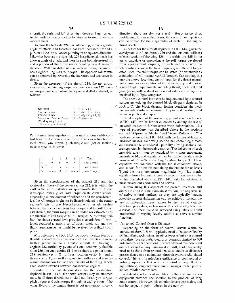
Given the geometry of the aircraft 210, the net thrust, yawing torque, pitching torque and center section 222 twist- ing torque can be calculated by a person skilled in the art, as follows:
Net thrust TI +T2 +T3 +T4 Yawing Torque Pitching Torque
- T4)y1 + (T2 - T3)y2 + T4)z1 + (T2 + T3)z2
Midsection Twisting Torque (Yielding wing tips at different angles of attack)
(TI - T4)(z,+ z2)
Partitioning these equations out in matrix form yields con- trol laws for the four engine thrust levels as a function of total thrust, yaw torque, pitch torque and (center section) twist torque, as follows:
Given the aerodynamics of the aircraft 210 and the torsional stiffness of the center section 222, it is within the skill in the art to calculate or approximate the roll torque developed from a given twist torque on the center section. Depending on the amount of deflection and the aerodynam- ics, the roll torque might not be linearly related to the center section’s twist torque. Nevertheless, with the relationship between the (center section) twist torque and the roll torque established, the twist torque can be stated (or estimated) as a z function of roll torque: z(Rol1 Torque). Substituting this into the above control laws provides a calculation of thrust levels required to meet a set of thrust, pitch, roll and yaw flight requirements, as might be received by a flight com- puter.
With reference to FIG. 14B, the above idealization of a flexible aircraft within the scope of the invention can be further generalized to a flexible aircraft 230 having n engines 232 carried by pylons 234 on a torsionally flexible wing 236. For each engine i(i=l to n), there is a pylon mount 238 position vector X,, a thrust location vector E,, and a thrust vector T,, as well as geometry, stiffness and aerody- namic information for each section 240 of the wing, where each section extends between consecutive engines.
Similar to the calculations done for the idealization depicted in FIG. 14A, the thrust vectors may be summed (now in all three directions) to yield net thrust, yaw torque, pitch torque, and twist torque throughout each portion of the wing. Because the engine thrust is not necessarily in the x
16 direction, there are also net y and z forces to consider. Partitioning this in matrix form, the control law equations can be solved for the magnitudes of each T,, the engine thrust levels.
As before for the aircraft depicted in FIG. 14A, given the aerodynamics of the aircraft 230 and the torsional stiffness of each section of the wing 236, it is within the skill in the art to calculate or approximate the roll torque developed from a given twist torque zk on each section k. With the
10 relationship between the twist torques zk and the roll torque established, the twist torque can be stated (or estimated) as a function of roll torque: -ck(Roll Torque). Substituting this into the above described control laws for the thrust magni- tudes provides a calculation of thrust levels required to meet
15 a set of flight requirements, including thrust, pitch, roll, and yaw, (along with vertical motion and side slip) as might be received by a flight computer.
The above control laws can be implemented by a control system embodying the control block diagram depicted in
20 FIG. 14C. The block diagram further considers the well- known relationships between roll, yaw and heading, and between pitch and airspeed.
The description of the invention, provided with reference to FIG. 14B, can be further extended by adding the use of
25 movable masses to further cause wing deformations. This type of procedure was described above in the sections entitled “Adjustable Dihedral” and “Active Roll control.” To analyze the aircraft of FIG. 14B, with the further addition of movable masses, each wing section 240 containing a mov-
30 able mass can be considered a plurality of wing sections that are separated by the movable masses. The deflection of each movable mass j can be quantized by a mass movement magnitude M,, and equations can be formed relating each movement M, with a resulting twisting torque T,. These
35 equations are combined with the thrust equations, above, and solved for a matrix containing the engine thrust levels T,and the mass movement magnitudes M,. This matrix equation forms the control laws for a control system, similar to that described above in FIG. 14C, with the addition of
40 mass movement commands and servos. In sum, using this aspect of the present invention, full
aircraft control can be maintained without the requirement of active control surfaces as they are typically known. Flexible aircraft deformation can be achieved through the
45 use of differential thrust andor by the use of variable structural properties, such as mass. It is noteworthy here that a variable stiffness could be achieved using tubes of liquid pressurized to varying levels, could also serve a similar function.
Unmanned Control from a Distance Depending on the form of control system within an
unmanned aircraft, it will typically need to be controlled by skilled pilots, technicians, or other types of mission-control
55 specialists. Typical radio-control is generally limited to 400 mile line-of-sight operations. Control of the above-described aircraft, or indeed any unmanned aircraft, could frequently need to be done from around obstacles andor at distances greater than can be maintained through typical radio-signal
60 control. This is of particular significance to commercial or military operators that wish to control a large fleet of high-altitude, long-endurance aircraft using a limited pool of skilled mission controllers.
A dedicated network of satellites or other communication 65 equipment provides one solution to the problem of long
range control. However, this solution is very expensive, and can be subject to point failures in the network.
5
50
US 7,198,225 B2 17
The present invention provides a control communication system for highly reliable control over the above unmanned aircraft, or any aircraft, at significantly lower cost than a dedicated control system. Indeed, this aspect of the present invention has the potential for applications far outside the relevant art of aircraft inventions, and it could be used for communication andor control in a wide variety of situa- tions.
Most parts of the world are interconnected through a wide variety of competing and complementary communication systems such as the Internet, land line telephone networks (leased or public), terrestrial wireless networks, cable modem networks, air phone networks, satellite networks, and other such systems. Such networks are themselves complex systems, and many are designed to provide on the order of 99.99% reliability, reliability being defined as the probability that the system is working during its lifetime. Nevertheless, any one of these systems is not likely to provide the preferred level of reliability to operate the aircraft.
In this aspect of the present invention, adequate reliability is maintained by using a plurality of partially, substantially or (most preferably) fully redundant communication paths, (i.e., redundant communication subsystems, to transmit and or receive signals between the mission controller and the aircraft). Preferably, the invention includes a controller that controls the use of a first, primary communications sub- system and a second, alternate communications subsystem, each typically made from a plurality of system components. To be fully redundant, the subsystems cannot share any critical link. Alternatively, the systems can be partially redundant, having only limited shared critical links that preferably exhibit higher than normal reliability, or are at least under the control of an entity having an interest in the aircraft.
Care must be taken to assure that seemingly different systems are not, in fact, sharing a common critical commu- nications link. For example, one long distance telephone network might in fact lease lines from another network, and thus share a critical link. Therefore, it is best to select service providers that maintain their own communications back- bone.
Typically, there will be three classes of subsystem com- ponents: backbone links (such as comprising fiberoptic networks, microwave transmission networks, satellite net- works, coaxial cable networks, or copper wire networks), aircraft access links (such as radio links between the back- bone links and the aircraft), and mission controller links (such as land phone lines, cell phone connections, micro- wave links or direct satellite links between the backbone and the mission controller).
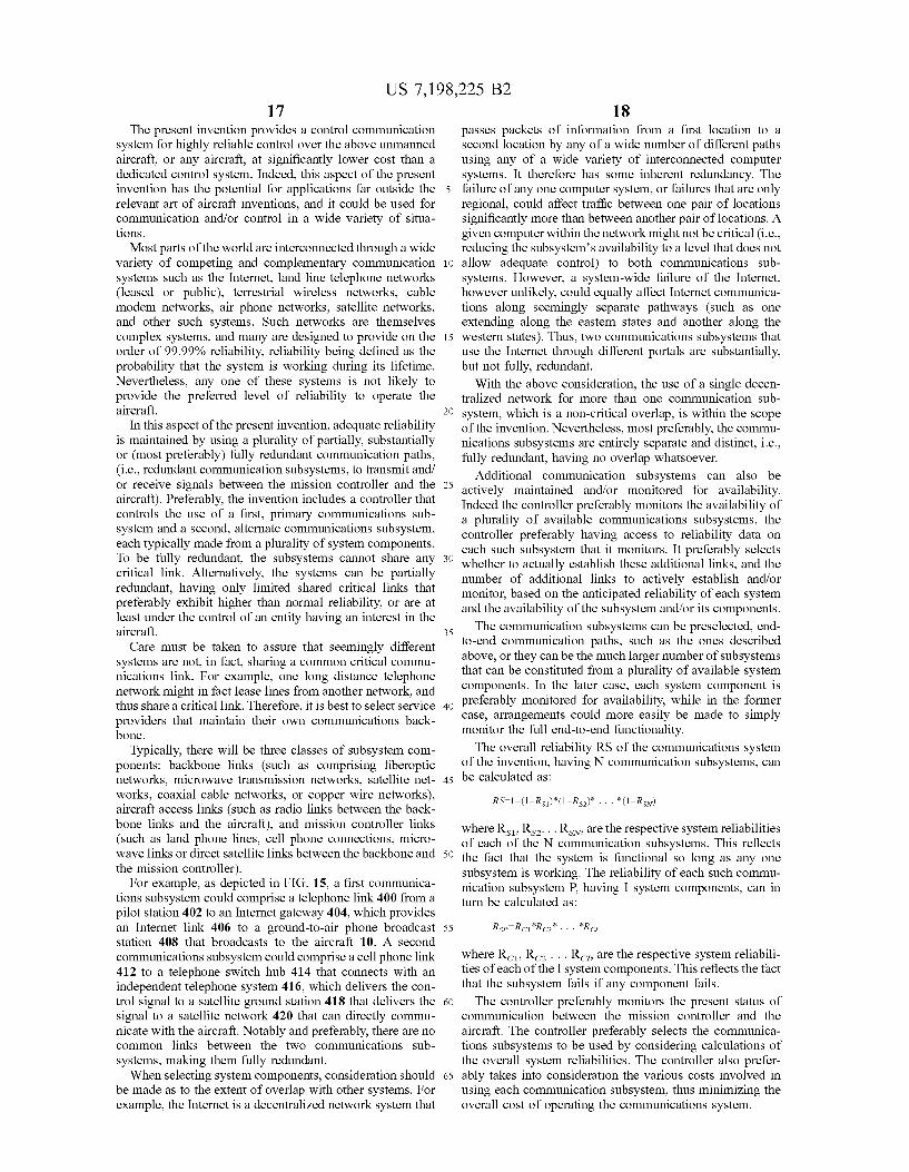
For example, as depicted in FIG. 15, a first communica- tions subsystem could comprise a telephone link 400 from a pilot station 402 to an Internet gateway 404, which provides an Internet link 406 to a ground-to-air phone broadcast station 408 that broadcasts to the aircraft 10. A second communications subsystem could comprise a cell phone link 412 to a telephone switch hub 414 that connects with an independent telephone system 416, which delivers the con- trol signal to a satellite ground station 418 that delivers the signal to a satellite network 420 that can directly commu- nicate with the aircraft. Notably and preferably, there are no common links between the two communications sub- systems, making them fully redundant.
When selecting system components, consideration should be made as to the extent of overlap with other systems. For example, the Internet is a decentralized network system that
18 passes packets of information from a first location to a second location by any of a wide number of different paths using any of a wide variety of interconnected computer systems. It therefore has some inherent redundancy. The
5 failure of any one computer system, or failures that are only regional, could affect traffic between one pair of locations significantly more than between another pair of locations. A given computer within the network might not be critical (i.e., reducing the subsystem’s availability to a level that does not
i o allow adequate control) to both communications sub- systems. However, a system-wide failure of the Internet, however unlikely, could equally affect Internet communica- tions along seemingly separate pathways (such as one extending along the eastern states and another along the
15 western states). Thus, two communications subsystems that use the Internet through different portals are substantially, but not fully, redundant.
With the above consideration, the use of a single decen- tralized network for more than one communication sub-
20 system, which is a non-critical overlap, is within the scope of the invention. Nevertheless, most preferably, the commu- nications subsystems are entirely separate and distinct, i.e., fully redundant, having no overlap whatsoever.
Additional communication subsystems can also be 25 actively maintained andor monitored for availability.
Indeed the controller preferably monitors the availability of a plurality of available communications subsystems, the controller preferably having access to reliability data on each such subsystem that it monitors. It preferably selects
30 whether to actually establish these additional links, and the number of additional links to actively establish andor monitor, based on the anticipated reliability of each system and the availability of the subsystem andor its components.
The communication subsystems can be preselected, end- to-end communication paths, such as the ones described above, or they can be the much larger number of subsystems that can be constituted from a plurality of available system components. In the later case, each system component is
4o preferably monitored for availability, while in the former case, arrangements could more easily be made to simply monitor the full end-to-end functionality.
The overall reliability RS of the communications system of the invention, having N communication subsystems, can
35
45 be calculated as:
RS=l-(l-R,,)*(l-R,)* . . . *(l-RsN)
where Rsl, Rs2. . . RsN, are the respective system reliabilities of each of the N communication subsystems. This reflects
50 the fact that the system is functional so long as any one subsystem is working. The reliability of each such commu- nication subsystem P, having I system components, can in turn be calculated as:
55 R,=R,,*R,*. . . *R,
where R,,, R, . . . R , are the respective system reliabili- ties of each of the I system components. This reflects the fact that the subsystem fails if any component fails.
The controller preferably monitors the present status of communication between the mission controller and the aircraft. The controller preferably selects the communica- tions subsystems to be used by considering calculations of the overall system reliabilities. The controller also prefer-
65 ably takes into consideration the various costs involved in using each communication subsystem, thus minimizing the overall cost of operating the communications system.
60
US 7,198,225 B2 19 20
Advantageously, this communications system will typi- must have the ability to track its target. Furthermore, to the cally provide the ability to communicate with an aircraft extent that the signal strength can be increased, the increase almost worldwide using primarily existing communications broadens the geographic area that will experience significant infrastructure, which will likely simplifies the deployment interference from the signal, particularly if the signal has a and relocation of aircraft systems. Existing system compo- 5 wide beamwidth or is omnidirectional (such as is used for nents typically have established communication frequen- cellular communications). In sum, the communications cies, and generally have known reliability, providing for bandwidth is limited by the altitude of the satellite above the reduced startup and operational costs. The superior reliabil- ground station, by the maximum ground distance (Le., ity of the components will likely lead to efficient aircraft degrees latitude and longitude) between the ground station control, which in turn can provide for reduced power i o and the satellite, by receiver sensitivity (such as from requirements, thus leaving more power for use by an air- antenna size), by beamwidth, and by power level. Addition- craft’s payload. ally, for at least some applications, the communications
bandwidth is limited by background noise levels and by Missions for the Aircraft limitations on the allowable interference with other loca- As noted above, the aircraft of the preferred embodiment 15 tion’s signals. Furthermore, if narrow beamwidth ground is ideally suited for certain types of prolonged missions. station antennas are used to reduce the power requirements, These include monitoring weather, providing a mobile, significant costs can be incurred and additional risks of reusable communications platform, performing surveil- failure can occur due to the precision of the tracking lance, testing atmospheric conditions, and many other activi- requirements. ties as well. For example, the preferred embodiment can be Satellite-to-satellite communication signals, or satellite to used for to high altitude weather surveillance, and have its non-orbiting spacecraft uplinks, do not necessarily suffer course or flight pattern changed to follow a hurricane at high these types of constraints, as they can use high frequency altitudes, where the aircraft is well out of danger. signals, e.g., lasers or other optical signals, to achieve a The aircraft is designed to fly continuous, unmanned broad bandwidth over large distances with limited power. missions of 3000 hours, or longer, which is greater than the 25 Those signals can degrade rapidly when passing through mean time between overhauls for most aircraft. Therefore, atmospheric phenomena such as clouds. Therefore such high the aircraft is designed with reliability foremost in mind. frequency communication signals are typically limited to This reliability is at least partially aided using redundancy, inter-satellite communication, or to communication between that is, by providing many back-up systems aboard the satellites and ground locations that do not tend to experience aircraft.
Satellite Downlink System The preferred embodiment of the present invention can With reference to FIG. 16A, one type of mission, for provide for a significant increase in ground-to-space com-
which the aircraft 10 of the invention is well suited, is the munication bandwidths by providing a suborbital platform establishment of high bandwidth ground to space commu- 304 to transform a radio wave signal from a ground station nication system, from a spacecraft located at orbital altitudes 35 300, such as a microwave signal, to an optical signal directed or higher, such as a satellite, to a ground station. More toward a satellite, or other spacecraft. While this commu- particularly, the aircraft is particularly well suited to serve as nication link could be in either direction, preferably the part of a satellite downlink system, which would also communication link is bidirectional. include a satellite 302, a ground station 300, and the signals For this function, the preferred suborbital platform, the traveling between them. This type of mission can be useful 40 aircraft 10 of the invention, includes a microwave trans- in the architecture of a wide variety of communication ceiver 310 with a downward-pointing antenna for commu- systems. nicating with a microwave transceiver 312 with an upward-
Typically, communications between a ground station and pointing antenna at the ground station, and an optical a satellite use some type of radio wave signal, such as a transceiver 314 with an upward-pointing antenna for com- microwave signal, which can pass through various atmo- 45 municating with an optical transceiver 316 with a down- spheric phenomena, such as clouds, without interference. ward-pointing antenna in the satellite. The aircraft is pref- Some of these signals are omnidirectional, and some are erably elevated to an altitude above typical altitudes for directed toward a target with a given beamwidth. However, substantial atmospheric optical interference, such as from for a given level of receiver sensitivity and background clouds 318, and preferably low enough to maximize signal noise, the signal strength that is required to carry a particular 50 bandwidths between the ground station and the aircraft. bandwidth increases substantially with the distance between Preferably the aircraft has a plurality of antennas for ground the ground station and the satellite, even if the broadcasting stations, each of these ground-oriented antennas preferably antenna has a relatively narrow beamwidth. Receiver sen- being aimable. sitivity can be increased with antenna size, but that carries Most preferably the aircraft operates between the altitudes a mass tradeoff, which is costly for satellite systems. Fur- 55 of 50,000 feet and 70,000 feet, and does so for 200 hours or thermore, with the limited exception of geostationary satel- longer (and more preferably for 300 hours or longer). The lites, satellites follow a groundtrack crossing back and communications system created, using this aircraft, prefer- fourth over the equator that causes variation in their distance ably operates at a ground station microwave power level that and direction from the ground station and requires large would prohibit significant communication (i.e., communi- pointing adjustments in directional antennas (such as to 60 cation of a significant bandwidth) over the distance between periodically switch from satellite to satellite). Depending on the ground and low-orbit altitudes. the ground track of the satellite (or group of satellites), Preferably, the aircraft is stationed in a relatively station- ground stations may require extensive amounts of power to ary position with respect to the ground, thus limiting or maintain a downlink with distant satellites. removing the necessity for the ground station to track the
Therefore, the signal strength is typically a limiting factor 65 aircraft. In particular, the aircraft preferably operates within on the available bandwidth for the downlink, and, for a 7000-foot diameter circle, and with a 1000 foot altitude directional ground station, the directional antenna typically range, and more preferably substantially within or close to
20
30 atmospheric phenomena such as clouds.

US 7,198,225 B2 21
a 4000-foot diameter circle. Furthermore, the aircraft pref- erably operates within a 1000 foot vertical range, or more preferably within or close to a 100-foot vertical range.
Acting as a suborbital platform to relay radio wave signals 306 from a ground station 300 through to a satellite 302 using optical signals 308, the aircraft provides numerous advantages, and can conduct various missions. For example, such an aircraft can be quickly replaced if it develops mechanical dificulties. Likewise, such aircraft can operate within a relatively close distance to each other, using fre- quencies that could interfere with each other at higher power levels (for broad beamwidth or omnidirectional signals), because the radio wave signals to each of the aircraft are of a substantially lower power level than would be required to provide a similar bandwidth to a satellite in orbit. This can be further augmented with a closed loop signal-strength control system to minimize power usage to necessary levels for the various signals.
By using upward-pointing ground antennas andor down- ward-pointing satellite antennas having limited beamwidth, the power usage can be further minimized. Each of these aimable antennas delimits an area of airspace that the aircraft must remain within. If both an upward-pointing ground antenna and a downward-pointing satellite antenna are used, they must be aimed to mutually define an area of airspace that the aircraft can maintain a flight pattern within.
To maintain station within the delimited airspace, the aircraft will preferably be a slow flying aircraft. The flight pattern will typically be aspirin shaped, being generally circular, with a certain amount of vertical variation. How- ever, it should be understood that in high wind conditions, the preferred flight pattern could vary from a zig-zagging pattern where the aircraft tacks back and fourth in a gener- ally upwind direction, to a straight upwind flight.
The aircraft can function to facilitate communication between a single ground station and a single spacecraft, such as a geostationary (or other geosynchronous) satellite, or it can communicate with a series of lower orbiting satellites that sequentially pass within the aircraft’s range of optical communication, as depicted in FIG. 16A. Preferably, an aircraft designed for switching between satellites will include two optical communications devices 314, 320, so as to acquire a communication link with a second satellite 322 before breaking its communication link with the first satel- lite 302.
As depicted in FIG. 16B, in one mission variation, the aircraft 10 can be used at more northern or southern lati- tudes, where constant and direct access to communications satellites might not otherwise be readily available. By sta- tioning the aircraft at adequate suborbital altitudes, the aircraft can establish communications with satellites 324 that are more than SO degrees latitude away, the satellite likely being closer to the Equator.
The aircraft can advantageously take advantage of most any non-equatorial station by using directional signals that reuse wavelengths that are dedicated to equatorial satellites. In particular, a particular ground station can directionally broadcast two different signals using the same wavelength, by directing one toward a geosynchronous satellite and the other toward the aircraft. Unlike non-equatorial satellites, the aircraft is not required to cross the equator, and thus the ground station need not periodically switch to a new broad- cast direction (such as occurs when the ground station must switch satellites). Naturally, for a given aircraft location, some ground stations will not be able to broadcast on the same frequency as is broadcast to the satellite because the two directional signals will overlap (e.g., the signals might
5
10
15
20
25
30
35
40
45
50
55
60
6 5
22 overlap if the aircraft is somewhat north of the equator and the ground station is farther north of the equator).
Likewise, as depicted in FIG. 16C, the system can be used to circumvent mountains 325 and other obstacles. This feature can be used for ground station to satellite linkups, and likewise used for ground station to ground station linkups. This is a particularly effective use of the system, since neither ground stations nor satellites are typically repositionable without great effort andor expense. One potentially effective use for such a system is overcoming the effect of obstacles on signals that are widely broadcast, such as television signals. The source of these television signals could be a ground station, a satellite, or even another aircraft. Another potentially effective use is frequency reuse in broadcasting to multiple, geographically separated ground stations using the same frequency. This is advantageous in that the satellite, being farther away, would require a nar- rower beam width to have separate communications with the two ground stations using the same frequency.
Another related mission for one or more of the aircraft 10 is in a communications system where the aircraft serve as regional hubs, relaying communications between end users located in spot beams, and communications networks. The communications networks can be either terrestrial based, accessed via ground antennas or space based, accessed via optical or extremely high frequency microwave links.
One such related mission, depicted in FIG. 16D, is as a communications hub, communicating simultaneously between a ground station 326 and a plurality of satellites 328. In this mission, the aircraft would require a larger number of optical transceivers, and would need to generate additional power to operate the transceivers. Alternately, as depicted in FIGS. 16E and 16F, two coverage regions are shown with one airplane providing coverage over each one. In particular, one or more of such aircraft 10 can all communicate with a single satellite 330, thus connecting one or more ground stations with a single satellite that acts as a communications hub. This potentially provides for fre- quency reuse by each aircraft (i.e., each aircraft can use the same set of available frequencies), increasing the available bandwidth between the satellite and the ground.
This scenario can provide for increased bandwidth between a densely populated area and a satellite (see, FIG. 16E), or between a satellite and two distant locations (see, FIG. 16F). The later scenario provides for extremely high amounts of data to be passed between a satellite and a city. It provides for different paths to reuse lower frequencies near the ground, and optical or extremely high frequency micro- wave links to communicate between the aircraft and the satellite. That satellite can, in turn, act as a hub and com- municate with one or more other satellites 334, which can also use suborbital platforms for ground communication. Additionally, direct aircraft to aircraft communications can also be used. As these examples demonstrate, the aircraft can serve as part of the architecture of a variety of communi- cations systems.
While the above-described preferred embodiment used microwave and optical signals, it should be understood that the system is operable for a wide variety of signals. In particular, it is known that atmospheric moisture interferes significantly with radio wavelengths of approximately one millimeter or smaller (i.e., higher frequency signals, above twenty gigahertz), but not as much with greater wavelengths (i.e., lower frequency signals, below twenty gigahertz). Thus, the system can preferably be operated using a ground station to aircraft radio signal having a wavelength greater than one millimeter, and an aircraft-to-satellite radio signal
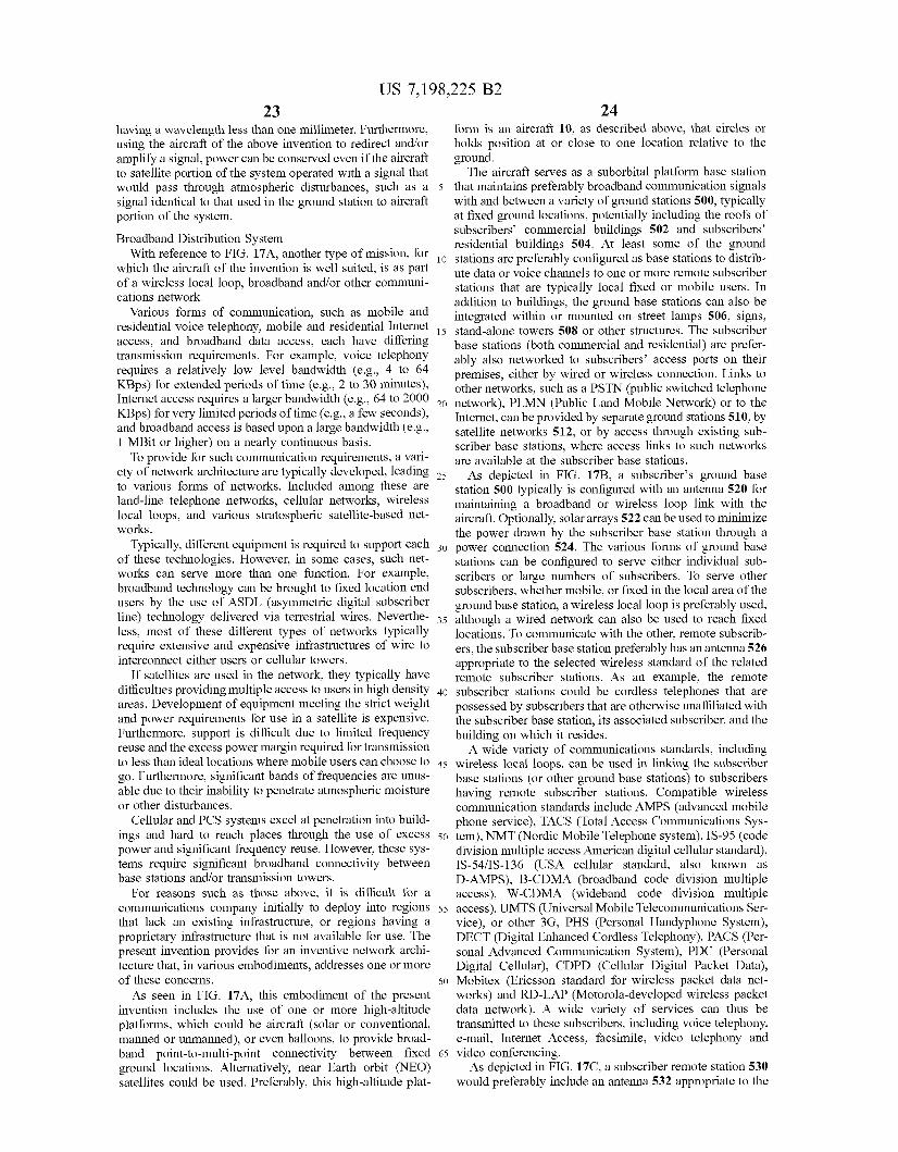
US 7,198,225 B2 23 24
having a wavclength less than one millimeter. Furthermore, form is an aircraft 10, as described above, that circles or using the aircraft of the above invention to redirect andor holds position at or close to one location relative to the amplify a signal, power can be conserved even if the aircraft ground. to satellite portion of the system operated with a signal that The aircraft serves as a suborbital platform base station would pass through atmospheric disturbances, such as a 5 that maintains preferably broadband communication signals signal identical to that used in the ground station to aircraft with and between a variety of ground stations 500, typically portion of the system. at fixed ground locations, potentially including the roofs of
subscribers’ commercial buildings 502 and subscribers’ residential buildings 504. At least some of the ground Broadband Distribution System
which the aircraft of the invention is well suited, is as part ute data or voice channels to one or remote subscriber
addition to buildings, the ground base stations can also be cations network. Various forms of communication, such as mobile and integrated within or mounted on street lamps 506, signs,
residential voice telephony, mobile and residential Internet 15 stand-alone towers 508 or other ne subscriber access, and broadband data access, each have differing base stations (both commercial and residential) are prefer- transmission requirements. For example, voice telephony ably also lletworked to subscribers’ access ports on their
with reference to 17A, another type Of for 10 stations are preferably configured as base stations to distrib-
Of a local loop, broadband other communi- stations that are typically local fixed or mobile users, In
requires a to 64 KBPs) for extended periods Of time (e.g.> 2 to 30 minutes),
KBps) for limited periods Of time (e.!&> a few seconds),
low level bandwidth (e.g.> premises, either by wired or wireless connection. Links to other networks, such as a PSTN (public switched telephone
Internet, can be provided by separate ground stations 510, by
Internet access requires a larger bandwidth (e.g., 64 to 2000 20 network), PLMN (Public Land Mobile Network) or to the
and broadband access is based upon a large bandwidth (e%., satellite networks 512, or by access through existing sub- 1 MBit or higher) on a nearly continuous basis. scriber base stations, where access links to such networks
To provide for such communication requirements, a vari- are available at the subscriber base stations, ety of network architecture are typically developed, leading 25 depicted in FIG. 17B, a subscriber’s ground base to various forms of networks. Included among these are station 500 typically is configured with an antenna 520 for land-line telephone networks, cellular networks, wireless maintaining a broadband or wireless loop link with the local loops, and various stratospheric satellite-based net- aircraft. Optionally, solar arrays 522 can be used to minimize works. the power drawn by the subscriber base station through a
Typically, different equipment is required to support each 30 power connection 524. The various forms of ground base of these technologies. However, in some cases, such net- stations to Serve either individual sub- works can Serve more than one function. For example, scribers or large numbers of subscribers. To serve other broadband technology Can be brought to fixed location end subscribers, whether mobile, or fixed in the local area of the users by the use of ASDL (asymmetric digital subscriber ground base station, a wireless local loop is preferably used, line) technology delivered via terrestrial wires. Neverthe- 35 although a wired network can also be used to reach fixed less, most of these different types of networks tYPicallY locations. To communicate with the other, remote subscrib- require extensive and expensive infrastructures of wire to ers, the subscriber base station preferably has an antenna 526 interconnect either users or cellular towers. appropriate to the selected wireless standard of the related
If satellites are used in the network, they typically have remote subscriber stations. As an example, the remote difficulties Providing multiple access to users in hi!& density 40 subscriber stations could be cordless telephones that are areas. Development of equipment meeting the strict weight possessed by subscribers that are otherwise unaffiliated with and Power requirements for use in a satellite is expensive. the subscriber base station, its associated subscriber, and the Furthermore, support is difficult due to limited frequency building oI1 which it resides, reuse and the excess power margin required for transmission A wide variety of communications standards, including to less than ideal locations where mobile users can choose to 45 wireless local loops, can be used in linking the subscriber go. Furthermore, SigifiCaIIt bands of frequencies are UnuS- base stations (or other ground base stations) to subscribers able due to their inability to penetrate atmospheric moisture having remote subscriber stations, Compatible wireless or other disturbances. communication standards include AMPS (advanced mobile
Cellular and PCS systems excel at penetration into build- phone service), TACS (Total Access Communications Sys- ings and hard to reach places through the use of excess 50 tem), NMT (Nordic Mobile Telephone system), IS-95 (code power and significant frequency reuse. However, these sys- division multiple access American digital cellular standard), tems require significant broadband connectivity between Is-54iIS-136 (USA cellular standard, also known as base stations andor transmission towers. D-AMPS), B-CDMA (broadband code division multiple
For reasons such as those above, it is difficult for a access), W-CDMA (wideband code division multiple communications company initially to deploy into regions 55 access), UMTS (Universal Mobile Telecommunications Ser- that lack an existing infrastructure, or regions having a vice), or other 3G, PHS (Personal Handyphone System), proprietary infrastructure that is not available for use. The DECT (Digital Enhanced Cordless Telephony), PACS (Per- present invention provides for an inventive network archi- sonal Advanced Communication System), PDC (Personal tecture that, in various embodiments, addresses one or more Digital Cellular), CDPD (Cellular Digital Packet Data), of these concerns. 60 Mobitex (Ericsson standard for wireless packet data net-
As seen in FIG. 17A, this embodiment of the present works) and RD-LAP (Motorola-developed wireless packet invention includes the use of one or more high-altitude data network). A wide variety of services can thus be platforms, which could be aircraft (solar or conventional, transmitted to these subscribers, including voice telephony, manned or unmanned), or even balloons, to provide broad- e-mail, Internet Access, facsimile, video telephony and band point-to-multi-point connectivity between fixed 65 video conferencing. ground locations. Alternatively, near Earth orbit (NEO) As depicted in FIG. 17C, a subscriber remote station 530 satellites could be used. Preferably, this high-altitude plat- would preferably include an antenna 532 appropriate to the
be
US 7,198,225 B2 25 26
wireless standard used by the subscriber remote station’s related ground base station. These subscriber remote stations would have wired or wireless networked connections 534 to the individual devices of the subscribers.
As can be seen from the above description of this distri- 5 bution system, this aspect of the invention provides for an information distribution system without the installation of an extensive infrastructure. Instead, the system requires only individual subscriber base stations located with the subscrib- ers, or other ground stations, and one or more preferably i o high altitude, suborbital platforms providing communication links to and between the ground stations.
While a particular form of the invention has been illus- trated and described, it will be apparent that various modi- fications can be made without departing from the spirit and 15
been described in detail with reference only to the preferred embodiments, those having ordinary skill in the art will appreciate that various modifications can be made without departing from the invention. Accordingly, the invention is 20 not intended to be limited by the above discussion, and is defined with reference to the following claims.
dihedral causes at least one motor of the plurality of motors produces thrust below the aircraft’s center of drag, and thereby an upward pitching moment, when the aircraft is in flight; and
a control system connected to the throttles, wherein the control system is configured such that it controls the throttles to control the pitch of the aircraft.
2. The aircraft of claim 1, wherein the aircraft is con- trolled without the use of elevators,
3, The aircraft of claim 1, wherein pitching moments generated by the motors on a first side of the aircraft are controlled relative to pitching moments generated by the motors on a second side of the aircraft to avoid torque between the first and second sides of the aircraft,
4, The aircraft of claim 1, wherein motors on a first side scope Of the invention. Thus, the invention has of the aircraft are controlled to produce the Same pitching
moment as motors on a second side of the aircraft, 5. The aircraft of claim 1, wherein the control system
controls pitch by actively adjusting only one set of motors from the group of: the set of motors above the center of drag and the set of motors below the center of drag.
6. The aircraft of claim 1, wherein the control system is further configured to control the throttles so as to control
7. The aircraft of claim 6, wherein the control system is further configured to control the throttles so as to control aircraft
8. The aircraft of claim 1, wherein the control system is
We claim: 1. An aircraft, comprising: a laterally extending, flexible wing, configured to develop 25 aircraft yaw.
dihedral during flight; a plurality ofmotors mounted on the wing, at least
of the plurality of motors having throttles that control the thrust of at least some of the plurality of motors,
plurality of motors to produce thrust above the air- craft’s center of drag, and thereby a downward pitching
wherein the dihedral causes at least one motor of the 30 further configured to control the throttles SO as to control roll of the aircraft.
moment, when the aircraft is in flight, and wherein the * * * * *
Related Documents