US009 197359B2 (12) United States Patent (10) Patent No.: US 9,197,359 B2 Aiba et al. (45) Date of Patent: Nov. 24, 2015 (54) MOBILESTATION APPARATUS, USPC .......................................................... 370/329 PROCESSING METHOD, AND INTEGRATED See application file for complete search history. CIRCUIT (56) References Cited (75) Inventors: Tatsushi Aiba, Osaka (JP); Shoichi U.S. PATENT DOCUMENTS Suzuki, Osaka (JP) M 2009/0274100 A1* 1 1/2009 Montojo et al. .............. 370,328 (73) Assignee: Sirr KABUSHIK KAISHA, Osaka 2010/0135272 A1* 6/2010 Dayal et al. ................... 370,343 (Continued) (*) Notice: Subject to any disclaimer, the term of this patent is extended or adjusted under 35 FOREIGN PATENT DOCUMENTS U.S.C. 154(b) by 240 days. CN 101202606. A 6, 2008 CN 101867467 A 10, 2010 (21) Appl. No.: 13/881,994 OTHER PUBLICATIONS (22) PCT Filed: Oct. 25, 2011 3GPP TSG RAN WG1 Meeting #62, R1-104431, “ULACK/NAK (86). PCT No.: PCT/UP2O11AO74496 Feedback in LTE-A TDD', Nokia, Nokia Siemens Networks, Agenda item: 6.2.2.1. Aug. 23-27, 2010. E. Jun. 17, 2013 (Continued) s 9 (87) PCT Pub. No.: WO2012/057109 Primary Examiner — Gerald Smarth (74) Attorney, Agent, or Firm — Birch, Stewart, Kolasch & PCT Pub. Date: May 3, 2012 Birch, LLP (65) Prior Publication Data (57) ABSTRACT US 2013/O258978A1 Oct. 3, 2013 A mobile station apparatus efficiently Switches coding O O schemes when coding both information indicating an ACK/ (30) Foreign Application Priority Data NACK and first control information. A mobile station appa ratus 200 determines a number of bits of information on a Oct. 29, 2010 (JP) ................................. 2010-243179 HARO based on a number of downlink subframes corre sponding to the information on a HARQ transmitted in a (51) Int. Cl. certain uplink subframe, a number of set serving cells, and a H0474/00 (2009.01) transmission mode set in each serving cell, applies spatial H04B 7/22 (2006.01) bundling to the information on a HARQ in a case where the (Continued) determined number of bits of the information on a HARQ exceeds a predetermined value, and selects one of a first (52) U.S. Cl. coding scheme and a second coding scheme based on the CPC ............. H04L I/001 (2013.01); H03M 13/136 number of bits of the information on a HARQ to which spatial (2013.01); H03M 13/35 (2013.01); bundling has been applied and a number of bits of a schedul (Continued) ing request and codes both the information on a HARO and (58) the scheduling request. 58) Field of Classification Search CPC ....................................................... HO4L 1 FOO1 9 Claims, 10 Drawing Sheets 200-: OBE w SA APARAT3 \ (MS.1) 2-2. KBE SAON APARAS ; ASE SA APARAS BS) 2-3: Most STAO ApparATS {MS3)

Welcome message from author
This document is posted to help you gain knowledge. Please leave a comment to let me know what you think about it! Share it to your friends and learn new things together.
Transcript

US009 197359B2
(12) United States Patent (10) Patent No.: US 9,197,359 B2 Aiba et al. (45) Date of Patent: Nov. 24, 2015
(54) MOBILESTATION APPARATUS, USPC .......................................................... 370/329 PROCESSING METHOD, AND INTEGRATED See application file for complete search history. CIRCUIT
(56) References Cited
(75) Inventors: Tatsushi Aiba, Osaka (JP); Shoichi U.S. PATENT DOCUMENTS Suzuki, Osaka (JP) M
2009/0274100 A1* 1 1/2009 Montojo et al. .............. 370,328 (73) Assignee: Sirr KABUSHIK KAISHA, Osaka 2010/0135272 A1* 6/2010 Dayal et al. ................... 370,343
(Continued) (*) Notice: Subject to any disclaimer, the term of this
patent is extended or adjusted under 35 FOREIGN PATENT DOCUMENTS U.S.C. 154(b) by 240 days. CN 101202606. A 6, 2008
CN 101867467 A 10, 2010 (21) Appl. No.: 13/881,994
OTHER PUBLICATIONS
(22) PCT Filed: Oct. 25, 2011 3GPP TSG RAN WG1 Meeting #62, R1-104431, “ULACK/NAK
(86). PCT No.: PCT/UP2O11AO74496 Feedback in LTE-A TDD', Nokia, Nokia Siemens Networks, Agenda item: 6.2.2.1. Aug. 23-27, 2010.
E. Jun. 17, 2013 (Continued) s 9
(87) PCT Pub. No.: WO2012/057109 Primary Examiner — Gerald Smarth (74) Attorney, Agent, or Firm — Birch, Stewart, Kolasch &
PCT Pub. Date: May 3, 2012 Birch, LLP
(65) Prior Publication Data (57) ABSTRACT
US 2013/O258978A1 Oct. 3, 2013 A mobile station apparatus efficiently Switches coding O O schemes when coding both information indicating an ACK/
(30) Foreign Application Priority Data NACK and first control information. A mobile station appa ratus 200 determines a number of bits of information on a
Oct. 29, 2010 (JP) ................................. 2010-243179 HARO based on a number of downlink subframes corre sponding to the information on a HARQ transmitted in a
(51) Int. Cl. certain uplink subframe, a number of set serving cells, and a H0474/00 (2009.01) transmission mode set in each serving cell, applies spatial H04B 7/22 (2006.01) bundling to the information on a HARQ in a case where the
(Continued) determined number of bits of the information on a HARQ exceeds a predetermined value, and selects one of a first
(52) U.S. Cl. coding scheme and a second coding scheme based on the CPC ............. H04L I/001 (2013.01); H03M 13/136 number of bits of the information on a HARQ to which spatial
(2013.01); H03M 13/35 (2013.01); bundling has been applied and a number of bits of a schedul (Continued) ing request and codes both the information on a HARO and
(58) the scheduling request. 58) Field of Classification Search
CPC ....................................................... HO4L 1 FOO1 9 Claims, 10 Drawing Sheets
200-: OBE
w SA APARAT3
\ (MS.1)
2-2. KBE SAON APARAS
; ASE
SA APARAS
BS)
2-3: Most STAO ApparATS {MS3)

US 9,197,359 B2 Page 2
(51) Int. Cl. H04L I/00 (2006.01) H03M I3/3 (2006.01) H03M I3/35 (2006.01) H03M, 3/00 (2006.01) H04L L/I6 (2006.01) H04L I/06 (2006.01)
(52) U.S. Cl. CPC ..... H03M 13/6306 (2013.01); H03M 13/6356
(2013.01); H03M 13/6362 (2013.01); H03M 13/6525 (2013.01); H04L I/0057 (2013.01);
H04L I/0067 (2013.01); H04L I/0073 (2013.01); H04L 1/1607 (2013.01); H04L I/06
(2013.01)
(56) References Cited
U.S. PATENT DOCUMENTS
2011/0205981 A1* 8, 2011 Koo et al. ..................... 370,329 2011/0243066 A1* 10/2011 Nayeb Nazaret al. ....... 370/328 2011/026.8090 A1* 1 1/2011 Quetal. ................ 370,335 2012/0084618 A1* 4/2012 Choudhury et al. .......... 714,752
OTHER PUBLICATIONS
3GPP TSG RAN WG1 meeting #62bis, R1-105247. “A/N coding schemes for large payload using DFT-S-OFDM”, Huawei, HiSilicon, Agenda Item: 6.2.1.1, Oct. 11-15, 2010. 3GPP TSGRAN WG1 MEETING #62bis, R1-105246, “ACK/NACK transmission schemes for TDD in LTE-A’, Huawei, HiSilicon, Agenda Item: 6.2.1.1, Oct. 11-15, 2010. 3GPP TR36.814V9.0.0, "3rd Generation Partnership Project; Tech nical Specification Group Radio Access Network: Evolved Universal Terrestrial Radio Access (E-UTRA); Further advancements for E-UTRA physical layer aspects (Release9). Mar. 2010. International Search Report, mailed Nov. 29, 2011, issued in PCT/ JP2011/074496. TSG-RAN WG1 #53bis, R1-082468, “Carrier aggregation in LTE Advanced”. Ericsson, Agenda Item: 12, Jun. 30-Jul. 4, 2008. CMCC et al., “Way Forward on Supporting ACKNAK Payload Larger than 11 Bits in Rel-10 TDD”, 3GPP TSG-RAN WG1 Meeting #62bis, Xi An, China, R1-105776, Oct. 11-15, 2010, 2 pages. Ericsson et al., “On ACKNACK codebook performance for carrier aggregation”, 3GPP TSG-RAN WG1 #62, R1-104840, Madrid, Spain, Aug. 23-27, 2010, 10 pages, XP-5045.0020.
* cited by examiner

US 9,197,359 B2 U.S. Patent
s
9 l

US 9,197,359 B2 Sheet 2 of 10 Nov. 24, 2015 U.S. Patent
{}{} {

197,359 B2 US 9 Sheet 3 of 10 2015 NOV, 24 U.S. Patent

U.S. Patent Nov. 24, 2015 Sheet 4 of 10 US 9,197,359 B2
FREENCY
SERNC CE SERN CE. SERVN G CE 3
--- (PRIMARY CELL) (SECONDARY CELL) (SECONDARY CELL) DLPCC DLSCC- SCC
(e.g. 2; Kiz) (e.g. 288/Hz), (e.g. 20 MHz)
ZZZZZZZZZZZZZZZACARRIER USEE FOR i. ONN in Y. till- ... COMMNCAON f
C SS : (e.g. 20MHz). (e.g. 20MHz). ...--& sm
CARRIER USE FOR NK
COMMUNICATION
YSCA NK W PHYSCA, WNNK 2 CONTROL CHANNEL (PCCH) CONTROL CHANNE (FDCCH)
-YSEA. N.NK YSCA. J.NK SHARE CHANNE. (PDSCH) SHARED CHANNE. (PJSCH)

U.S. Patent Nov. 24, 2015 Sheet 5 of 10 US 9,197,359 B2
8 SNCE FOR NORAN ook ook... o. CANG ACKNACK or of Oack.
CANNE CONGRA AC-N CCK
A.C.K. A.C. A.C.K.) g q 3. (77
CAEN 3
at: al ai d d " d.
SON BOCK
" Af AC: dick dACK 2 3
ai AC is d, d
X Y

U.S. Patent Nov. 24, 2015 Sheet 6 of 10 US 9,197,359 B2
X Y
REPLICATION BLOCK

197,359 B2 U.S. Patent

U.S. Patent Nov. 24, 2015 Sheet 8 of 10 US 9,197,359 B2
3 SECRENCE R NERVAN o ot'.
NCANGASA ACK * .
Division 3O CK
ook of OK ACK ACK 4CK /2 ACK/2 +
rack . AC ?olo 2-1 ... o2. CHANNELCODING! CHANNELCODING/ PUNCTURE BLOCK PUNCTURE BLOCK
ACK air (C. A CF i ACK i. g ( g c A{K} AC:{(i. G2. g4.
A. (
CAN SOCK
ACK A: dACK d is d
WSON BOCK
d ck do d s A. 2 3
Af " d. x2 Y2

U.S. Patent Nov. 24, 2015 Sheet 9 of 10 US 9,197,359 B2
X2 Y2
region RECAN BC- SOCK

U.S. Patent Nov. 24, 2015 Sheet 10 of 10 US 9,197,359 B2
BASE 3. STATION - 00 200 - STATION
APPARATUS APPARATUS
ACKINACK (e.g. ACKNACKS. Ooit) with SRC -
AEKiNACK -- RS CONR NFRfACN (e.g. ACKNACKS. Obit with SRMC
ACKNACK -- CRS CONRE NORAN (e.g. ACKNACKY Obit) with DRMC
ACKNACK (e.g. ACKNACKX (it sit R.C.

US 9, 197,359 B2 1.
MOBILE STATION APPARATUS, PROCESSING METHOD, AND INTEGRATED
CIRCUIT
TECHNICAL FIELD
The present invention relates to a mobile station apparatus, a processing method, and an integrated circuit.
BACKGROUND ART
3GPP (3rd Generation Partnership Project) is a project that examines and produces the specifications of a mobile com munication system based on a network in which W-CDMA (Wideband-Code Division Multiple Access) and GSM (reg istered trademark) (Global System for Mobile Communica tions) are developed. In the 3GPP, the W-CDMA system is standardized as a third-generation cellular mobile communi cation system, and its services have been launched one after another. Moreover, HSDPA (High-speed Downlink Packet Access) in which its communication speed is further increased is also standardized, and its services have been launched. In the 3GPP, a mobile communication system (hereinafter, LTE-A (Long Term Evolution-Advanced) or Advanced-EUTRA) is being examined which utilizes evolu tion of a third-generation radio access technology (hereinaf ter, LTE (Long Term Evolution) or EUTRA (Evolved Uni versal Terrestrial Radio Access)) and a wider frequency band to realize higher-speed data transmission/reception.
Here, as the communication system of the LTE-A, in the downlink, the introduction of an OFDMA method, which is a multicarrier communication method, is being examined, and in the uplink, the introduction of an SC-FDMA method and a DFT-precoded OFDM (DFT-s-OFDM with Spectrum Divi sion Control, Clustered-Single Carrier-Frequency Division Multiple Access) method, which are a single carrier commu nication method, is being examined.
Moreover, in the LTE-A, it is proposed that a plurality of frequency bands that has the same channel structure as the LTE and is contiguous and/or non-contiguous (which can be referred to as a carrier) (hereinafter, a Cell or a Component Carrier (CC)) is compositely used and is utilized as one wider frequency band (Cell aggregation or Carrier aggregation) (Non-patent document 1).
Here, the mobile station apparatus transmits, to the base station apparatus, information indicating an ACK/NACK (a Positive Acknowledgement/a Negative Acknowledgement, an ACK signal or a NACK signal) of HARQ (Hybrid Auto matic Repeat Request) indicating whether or not the decoding of a Downlink Transport Block (Downlink TB, hereinafter, also described as a transport block) received using a Physical Downlink Shared Channel (hereinafter, PDSCH) is suc ceeded, using a Physical Uplink Control Channel (hereinaf ter, PUCCH) or a Physical Uplink Shared Channel (herein after, PUSCH).
Furthermore, in the LTE-A, it is proposed that the base station apparatus applies MIMOSM(Multiple Input Multiple Output Spatial Multiplexing) to transmit the downlink trans port block to the mobile station apparatus (Non-patent docu ment 2). The MIMO SM refers to a technology in which a plurality of signals is multiplexed with the channels of a plurality of spatial dimensions realized by a plurality of trans mission antenna ports and a plurality of reception antenna ports and transmitted/received. Here, the antenna port refers to a logical antenna used for signal processing, and one antenna port can be formed with one physical antenna or can
10
15
25
30
35
40
45
50
55
60
65
2 be formed with a plurality of physical antennas. In addition, one transmission antenna port may correspond to one refer ence signal.
For example, the base station apparatus applies the MIMO SM to the PDSCH to transmit a plurality of transport blocks to the mobile station apparatus. In other words, the base station apparatus can apply the MIMOSM to the PDSCH to transmit a plurality of (for example, up to two) transport blocks to the mobile station apparatus. Further, for example, the base station apparatus can apply the MIMOSM to the PDSCH to perform a transmission to the mobile station with up to two Code Words (CWs). The mobile station apparatus transmits the information indicating the ACK/NACK (which may also be the HARQ information, the information indicat ing the ACK/NACK corresponding to the code word) for the transport block transmitted from the base station apparatus using the PUCCH or PUSCH.
Further, in the LTE-A, it is proposed that the mobile station apparatus performs Reed-Muller (hereinafter, RM) coding on the information indicating the ACK/NACK when transmit ting the information indicating the ACK/NACK to the base station apparatus. For example, it is proposed that the mobile station apparatus applies Double RM Coding (hereinafter, DRMC, Double RM Code, Dual RMCoding, Dual RM Code, a coding scheme utilizing two RM codes) to the information indicating the ACK/NACK as a Coding scheme when trans mitting the information indicating the ACK/NACK to the base station apparatus (Non-patent document 3). Here, in the LTE-A, TDD (Time Division Duplex) and FDD (Frequency Division Duplex) are supported.
PRIOR ART DOCUMENT
Non-Patent Document
Non-patent document 1: "Carrier aggregation in LTE-Ad vanced, 3GPP TSG RAN WG1 Meeting #53bis, R1-082468, Jun. 30-Jul. 4, 2008.
Non-patent document 2: “3GPP TR36.814 v9.0.0 (2010-03), Mar. 30, 2010.
Non-patent document 3: "A/N coding schemes for large pay load using DFT-S-OFDM, 3GPP TSG RAN WG1 Meet ing #62bis, R1-105247, Oct. 11-15, 2010.
DISCLOSURE OF THE INVENTION
Problems to be Solved by the Invention
However, in the prior art, there is no specific description of how to switch between the coding scheme utilizing the DRMC and a coding scheme utilizing Single RM Coding (hereinafter, SRMC, Single RM Code, a coding scheme uti lizing one RM code) when the mobile station apparatus encodes both the information indicating the ACK/NACK and uplink control information (for example, a Scheduling Request (SR) and Channel State Information (CSI), herein after, also described as first control information) other than the information indicating the ACK/NACK. The present invention is made in view of the foregoing
situations; an object of the present invention is to provide a mobile station apparatus, a processing method, and an inte grated circuit in which, when the mobile station apparatus encodes both the information indicating the ACK/NACK and the first control information, the mobile station apparatus can efficiently switch between the coding scheme utilizing the DRMC and the coding scheme utilizing the SRMC.

US 9, 197,359 B2 3
Means for Solving the Problems
(1) To achieve the above-mentioned object, the present invention takes the following measures. That is, a mobile station apparatus of the present invention is the one that communicates with a base station apparatus on a plurality of serving cells and includes: a unit configured to determine a number of bits of information on a HARQ based on a number of downlink subframes corresponding to the information on a HARO transmitted in a certain uplink subframe, a number of set serving cells, and a transmission mode set in each serving cell; a unit configured to apply spatial bundling to the infor mation on a HARQ in a case where the determined number of bits of the information on a HARQ exceeds a predetermined value; and a unit configured to select one of a first coding scheme and a second coding scheme based on the number of bits of the information on a HARQ to which the spatial bundling has been applied and a number of bits of a schedul ing request, and to code both the information on a HARO and the scheduling request.
(2) Further, the first coding scheme is a method for coding a bit sequence obtained by concatenating the bits of the infor mation on a HARQ and the bits of the scheduling request, and the second coding scheme is a method for separately coding respective bit sequences, which are obtained by concatenat ing the bits of the information on a HARQ and the bits of the scheduling request to generate a bit sequence and by dividing the generated bit sequence.
(3) Further, the spatial bundling applied to the information on a HARQ includes processing to perform an AND opera tion on the bits of the information on a HARQ corresponding to each of a first code word and a second code word, of a physical downlink shared channel received in each downlink Subframe in each serving cell.
(4) Further, the information on a HARQ is information indicating an ACK or NACK for the downlink transport block.
(5) Further, a processing method of a mobile station appa ratus that communicates with a base station apparatus on a plurality of serving cells, includes the steps of determining a number of bits of information on a HARQ based on a number of downlink subframes corresponding to the information on a HARO transmitted in a certain uplink subframe, a number of set serving cells, and a transmission mode set in each serving cell; applying spatial bundling to the information on a HARQ in a case where the determined number of bits of the infor mation on a HARQ exceeds a predetermined value; and selecting one of a first coding scheme and a second coding scheme based on the number of bits of the information on a HARO to which the spatial bundling has been applied and a number of bits of a scheduling request, and coding both the information on a HARQ and the scheduling request.
(6) Further, the first coding scheme is a method for coding a bit sequence obtained by concatenating the bits of the infor mation on a HARQ and the bits of the scheduling request, and the second coding scheme is a method for separately coding respective bit sequences, which are obtained by concatenat ing the bits of the information on a HARQ and the bits of the scheduling request to generate a bit sequence and by dividing the generated bit sequence.
(7) Further, the spatial bundling applied to the information on a HARQ includes processing to perform an AND opera tion on the bits of the information on a HARQ corresponding to each of a first code word and a second code word, of a physical downlink shared channel received in each downlink Subframe in each serving cell.
5
10
15
25
30
35
40
45
50
55
60
65
4 (8) Further, the information on a HARQ is information
indicating an ACK or NACK for the downlink transport block.
(9) Further, an integrated circuit mounted on a mobile station apparatus that communicates with a base station appa ratus on a plurality of serving cells, includes functions of determining a number of bits of information on a HARQ based on a number of downlink subframes corresponding to the information on a HARQ transmitted in a certain uplink Subframe, a number of set serving cells, and a transmission mode set in each serving cell; applying spatial bundling to the information on a HARQ in a case where the determined number of bits of the information on a HARQ exceeds a predetermined value; and selecting one of a first coding scheme and a second coding scheme based on the number of bits of the information on a HARQ to which the spatial bundling has been applied and a number of bits of a schedul ing request, and coding both the information on a HARO and the scheduling request.
(10) Further, the first coding scheme is a method for coding a bit sequence obtained by concatenating the bits of the infor mation on a HARQ and the bits of the scheduling request, and the second coding scheme is a method for separately coding respective bit sequences, which are obtained by concatenat ing the bits of the information on a HARQ and the bits of the scheduling request to generate a bit sequence and by dividing the generated bit sequence.
(11) Further, the spatial bundling applied to the informa tion on a HARQ includes processing to perform an AND operation on the bits of the information on a HARQ corre sponding to each of a first code word and a second code word, of a physical downlink shared channel received in each down link Subframe in each serving cell.
(12) Further, the information on a HARQ is information indicating an ACK or NACK for the downlink transport block.
Effect of the Invention
There are provided a mobile station apparatus, a commu nication method, and an integrated circuit in which, when the mobile station apparatus encodes both the information indi cating the ACK/NACK and the first control information, the mobile station apparatus can efficiently switch between the coding scheme utilizing the dual Reed-Muller code and the coding scheme utilizing the single Reed-Muller code.
BRIEF DESCRIPTION OF THE DRAWINGS
FIG. 1 is a diagram conceptually showing the configuration of physical channels according to an embodiment of the present invention;
FIG. 2 is a block diagram showing the schematic configu ration of abase station apparatus according to the embodi ment of the present invention;
FIG. 3 is a block diagram showing the schematic configu ration of a mobile station apparatus according to the embodi ment of the present invention;
FIG. 4 is a diagram showing an example of a mobile com munication system to which the embodiment of the present invention can be applied;
FIG. 5A is a diagram for explaining a coding scheme utilizing a single Reed-Muller code:
FIG. 5B is a diagram for explaining a coding scheme uti lizing the single Reed-Muller code:
FIG. 6 is a diagram showing an example of a code word of the Reed-Muller code:

US 9, 197,359 B2 5
FIG. 7A is a diagram for explaining a coding scheme utilizing a dual Reed-Muller code:
FIG. 7B is a diagram for explaining a coding scheme uti lizing the dual Reed-Muller code; and
FIG. 8 is a diagram for explaining a first embodiment.
BEST MODES FOR CARRYING OUT THE INVENTION
Next, an embodiment according to the present invention will be described with reference to the accompanying draw ings. FIG. 1 is a diagram showing an example of the configu ration of channels in the embodiment of the present invention. Downlink physical channels include a Physical Downlink Control Channel (PDCCH), a Physical Downlink Shared Channel (PDSCH), and the like. Uplink physical channels include a Physical UplinkShared Channel (PUSCH), a Physi cal Uplink Control Channel (PUCCH), and the like. The PDCCH is a channel that is used to notify (specify)
mobile station apparatuses 200-1 to 200-3 (the mobile station apparatuses 200-1 to 200-3 are also collectively represented by a mobile station apparatus 200) of the resource allocation of the PDSCH, HARQ processing information for downlink data, the resource allocation of the PUSCH, and the like. The mobile station apparatus 200, when the resource allo
cation of the PDSCH is transmitted on the PDCCH addressed to its own apparatus, receives, according to the resource allo cation indicated by using the PDCCH from a base station apparatus 100, using the PDSCH, a downlink signal (down link data (transport block for downlink shared channel (DL SCH)) and/or downlink control data (downlink control infor mation). In other words, the PDCCH can also be said to be a signal (a Downlink grant or a Downlink assignment) for performing the resource allocation for the downlink.
Moreover, the mobile station apparatus 200, when the resource allocation of the PUSCH is transmitted on the PDCCH addressed to its own apparatus, transmits, according to the resource allocation indicated by using the PDCCH from the base station apparatus 100, using the PUSCH, an uplink signal (uplink data (transport block for uplink shared channel (UL-SCH)) and/or uplink control data (uplink con trol information). In other words, the PDCCH can also be said to be a signal (an Uplink grant or an Uplink assignment) for allowing the data transmission for the uplink. The PDCCH is used for transmitting the Downlink Control
Information (DCI) such as the downlink assignment and the uplink assignment. The downlink assignment includes, for example, information for the allocation of the resources of the PDSCH transmitted by the base station apparatus 100 to the mobile station apparatus 200. The uplinkassignment includes information for the allocation of the resources of the PUSCH transmitted by the mobile station apparatus 200 to the base station apparatus 100. One downlink assignment includes information for the allocation of the resources of one PDSCH in a certain cell; and one uplink assignment includes infor mation for the allocation of the resources of one PUSCH in a certain cell.
Here, for the downlink control information, a plurality of downlink control information formats (DCI formats) is pre pared, and different DCI formats are used for different pur poses. For example, the DCI format is defined by the size and the order of a plurality of fields mapped onto the DCI format, the types of information mapped onto the fields, and the like.
For example, as the DCI format used as the downlink assignment, a DCI format 1/1A that is used when the PDSCH is transmitted by the base station apparatus 100 with a single antenna port (for example, one PDSCH cord word (one trans
10
15
25
30
35
40
45
50
55
60
65
6 port block) is transmitted) is defined. Moreover, for example, as the DCI format used as the downlink assignment, a DCI format 2 that is used when the PDSCH is transmitted by the base station apparatus 100 with multiple antenna ports (for example, up to two PDSCH cord words (up to two transport blocks) are transmitted) is defined. The PDSCH is a channel that is used for transmitting the
downlink data (transport block for the downlink shared chan nel (DL-SCH)) or paging information (paging channel: PCH). The base station apparatus 100 uses the PDSCH allo cated by the PDCCH to transmit the downlink transport block (transport block for the downlink shared channel (DL-SCH)) to the mobile station apparatus 200.
Here, the downlink data indicates, for example, user data; the DL-SCH is a transport channel. Moreover, a unit for transmitting the downlink data (DL-SCH) through the PDSCH is referred to as a Transport Block (TB); the transport block is a unit handled in a MAC (Media Access Control) layer. In the DL-SCH, a HARQ and dynamic adaptive radio link control are Supported, and beam forming is available. In the DL-SCH, dynamic resource allocation and quasi-static resource allocation are Supported.
Here, the transport block is associated with the Code Word (CW) in the physical layer. For example, the base station apparatus 100 can apply the MIMO SM to the PDSCH to perform a transmission with up to two code words. The PUSCH is a channel that is used for mainly transmit
ting the uplink data (transport block for the uplink shared channel (UL-SCH)). The mobile station apparatus 200 uses the PUSCH allocated by the PDCCH transmitted from the base station apparatus 100 to transmit the uplink transport block (transport block for the uplink shared channel (UL SCH)) to the base station apparatus 100.
Furthermore, when the base station apparatus 100 per forms scheduling on the mobile station apparatus 200, the Uplink Control Information (UCI) is transmitted using the PUSCH. Here, the uplink control information includes Chan nel State Information (CSI), Channel Quality Indicator (CQI), Precoding Matrix Indicator (PMI), and Rank Indicator (RI). The information indicating the ACK/NACK of HARQ for the downlink transport block (DL-SCH) is included in the uplink control information. The Scheduling Request (SR) which is used for requesting resource allocation for the trans mission of the uplink data (requesting a transmission through the UL-SCH) by the mobile station apparatus 200 is included in the uplink control information.
That is, the channel state information (CSI), the channel quality indicator (COI), the precoding matrix indicator (PMI), the rank indicator (RI), and the scheduling request (SR) are the uplink control information (the first control infor mation) other than the information indicating the ACK/ NACK
Here, the uplink data indicates, for example, user data; the UL-SCH is a transport channel. In addition, a unit for trans mitting the uplink data (UL-SCH) through the PUSCH is referred to as a Transport Block (TB); the transport block is a unit handled in the MAC (Media Access Control) layer. Moreover, the PUSCH and PUCCH are physical channels that are defined by (consists of) the time domain and the frequency domain. In the UL-SCH, a HARQ and dynamic adaptive radio link control are Supported, and the beam form ing is available. In the UL-SCH, dynamic resource allocation and quasi-static resource allocation are supported.
Furthermore, a radio resource control signal (hereinafter, a RRC signaling: a Radio Resource Control Signaling) exchanged between the base station apparatus 100 and the mobile station apparatus 200 may be included in the uplink

US 9, 197,359 B2 7
data (UL-SCH) and the downlink data (DL-SCH). Moreover, a MAC (Medium Access Control) control element exchanged between the base station apparatus 100 and the mobile station apparatus 200 may be included in the uplink data (UL-SCH) and the downlink data (DL-SCH). The base station apparatus 100 and the mobile station
apparatus 200 transmit and receive the RRC signaling in a higher layer (a Radio Resource Control Layer). In addition, the base station apparatus 100 and the mobile station appara tus 200 also transmit and receive the MAC control element in a higher layer (a Medium Access Control (MAC) layer). The PUCCH is a channel that is used for transmitting the
uplink control information. Here, the uplink control informa tion includes the channel state information (CSI), the channel quality indicator (COI), the precoding matrix indicator (PMI), and the rank indicator (RI). Furthermore, the informa tion indicating the ACK/NACK of HARQ for the downlink transport block (DL-SCH) is included in the uplink control information. The scheduling request (SR) for requesting resource allocation for the transmission of the uplink data (requesting a transmission through the UL-SCH) by the mobile station apparatus 200 is included in the uplink control information.
Configuration of the Base Station Apparatus 100 FIG. 2 is a block diagram showing the schematic configu
ration of the base station apparatus 100 according to the embodiment of the present invention. The base station appa ratus 100 includes a data control portion 101, a transmission data modulation portion 102, a radio portion 103, a schedul ing portion 104, a channel estimation portion 105, a reception data demodulation portion 106, a data extraction portion 107. a higher layer 108, and an antenna 109. In addition, the radio portion 103, the scheduling portion 104, the channel estima tion portion 105, the reception data demodulation portion 106, the data extraction portion 107, the higher layer 108, and the antenna 109 constitute a reception portion; the data con trol portion 101, the transmission data modulation portion 102, the radio portion 103, the scheduling portion 104, the higher layer 108, and the antenna 109 constitute a transmis sion portion. The antenna 109, the radio portion 103, the channel esti
mation portion 105, the reception data demodulation portion 106, and the data extraction portion 107 perform processing on the uplink physical layer. The antenna 109, the radio portion 103, the transmission data modulation portion 102. and the data control portion 101 perform processing on the downlink physical layer. The data control portion 101 receives the transport channel
from the scheduling portion 104. The data control portion 101 maps, onto the physical channel, the transport channel and a signal and a channel generated in the physical layer, based on the scheduling information input from the scheduling portion 104. The individual pieces of data mapped as described above are output to the transmission data modulation portion 102. The transmission data modulation portion 102 modulates
transmission data into an OFDM system. On the basis of the scheduling information from the scheduling portion 104 and a modulation scheme and a coding scheme corresponding to each PRB, the transmission data modulation portion 102 performs, on the data input from the data control portion 101, signal processing, Such as data modulation, coding, series/ parallel transform for an input signal, IFFT (Inverse Fast Fourier Transform) processing, CP (Cyclic Prefix) insertion, and filtering, generates transmission data and outputs it to the radio portion 103. Here, the scheduling information includes downlink physical resource block PRB (Physical Resource Block) allocation information, for example, physical
10
15
25
30
35
40
45
50
55
60
65
8 resource block position information formed with a frequency and time; the modulation scheme and the coding scheme corresponding to each PRB include, for example, informa tion, Such as a modulation scheme: 16 QAM and a coding rate: 2/3 coding rate. The radio portion 103 upconverts modulation data input
from the transmission data modulation portion 102 into a radio frequency to generate a radio signal, and transmits it through the antenna 109 to the mobile station apparatus 200. Moreover, the radio portion 103 receives, through the antenna 109, an uplink radio signal from the mobile station apparatus 200, downconverts it into a baseband signal and outputs the reception data to the channel estimation portion 105 and the reception data demodulation portion 106. The scheduling portion 104 performs processing on the
Medium Access Control (MAC) layer. The scheduling por tion 104 performs mapping of a logical channel and the trans port channel, scheduling (Such as HARQ processing and the selection of the transport format) on the downlink and the uplink, and the like. In the scheduling portion 104, in order to integrally control the processing portion of each physical layer, there are interfaces between the scheduling portion 104 and the antenna 109, the radio portion 103, the channel esti mation portion 105, the reception data demodulation portion 106, the data control portion 101, the transmission data modulation portion 102, and the data extraction portion 107 (however, not shown).
In the downlink scheduling, based on the uplink control information (such as the CSI, the CQI, the information indi cating the ACK/NACK, and the scheduling request) received from the mobile station apparatus 200, information on the PRB available for each mobile station apparatus 200, buffer status, the scheduling information input from the higher layer 108, and the like, the scheduling portion 104 performs pro cessing for selecting the downlink transportformat (transmis sion mode, that is, the allocation of physical resource blocks, the modulation scheme, the coding scheme, and the like) for modulating each piece of data, retransmission control on a HARO, and the generation of the scheduling information used in the downlink. The scheduling information used for the downlink scheduling is output to the data control portion 101.
Furthermore, in the uplink scheduling, based on the result of the estimation of the channel state (radio channel state) of the uplink output by the channel estimation portion 105, a resource allocation request from the mobile station apparatus 200, information on the PRBavailable for each mobile station apparatus 200, the scheduling information input from the higher layer 108, and the like, the scheduling portion 104 performs processing for selecting the uplink transport format (transmission mode, that is, the allocation of the physical resource blocks, the modulation scheme, the coding scheme, and the like) for modulating each piece of data and the gen eration of the scheduling information used in the uplink scheduling. The scheduling information used for the uplink scheduling is output to the data control portion 101.
In addition, the scheduling portion 104 also maps the downlink logical channel input from the higher layer 108 onto the transport channel, and outputs it to the data control portion 101. Moreover, the scheduling portion 104 also processes, as necessary, the control data and the transport channel input from the data extraction portion 107 and acquired through the uplink, thereafter maps them onto the uplink logical channel and outputs them to the higher layer 108.
In order to demodulate the uplink data, the channel estima tion portion 105 estimates the channel state of the uplink from an Uplink Demodulation Reference Signal (UDRS), and out puts the result of the estimation to the reception data demodu

US 9, 197,359 B2
lation portion 106. In order to perform the uplink scheduling, the channel estimation portion 105 also estimates the channel state of the uplink from an uplink measurement reference signal (Sounding Reference Signal (SRS)), and outputs the estimation result to the scheduling portion 104. The reception data demodulation portion 106 also serves as
an OFDM demodulation portion and/or a DFT-Spread OFDM (DFT-S-OFDM) demodulation portion that demodu lates the reception data modulated into the OFDM system and/or the SC-FDMA system. On the basis of the channel state estimation result of the uplink input from the channel estimation portion 105, the reception data demodulation por tion 106 performs demodulation processing by applying, to the modulation data input from the radio portion 103, signal processing Such as DFT transform, Subcarrier mapping, IFFT transform, and filtering, and outputs the demodulated data to the data extraction portion 107.
The data extraction portion 107 checks whether or not the data input from the reception data demodulation portion 106 is correct, and outputs the check result (ACK or NACK) to the scheduling portion 104. Furthermore, the data extraction por tion 107 separates the data input from the reception data demodulation portion 106 into the transport channel and the control data on the physical layer, and outputs them to the scheduling portion 104. The separated control data includes the CSI and the CQI transmitted from the mobile station apparatus 200, the information indicting the ACK/NACK, the scheduling request, and the like. The higher layer 108 performs processing on a Packet Data
Convergence Protocol (PDCP) layer, a Radio Link Control (RLC) layer, and a Radio Resource Control (RRC) layer. In the higher layer 108, in order to integrally control the pro cessing portion of a lower layer, there are interfaces between the higher layer 108 and the scheduling portion 104, the antenna 109, the radio portion 103, the channel estimation portion 105, the reception data demodulation portion 106, the data control portion 101, the transmission data modulation portion 102, and the data extraction portion 107 (however, not shown). The higher layer 108 has a radio resource control portion
110 (also called a control portion). In addition, the radio resource control portion 110 performs management on Vari ous types of setting information, management on system information, paging control, management on the communi cation state of each mobile station apparatus 200, mobility management such as handover or the like, management on the buffer status of each mobile station apparatus 200, manage ment on the connection setting of a unicast and a multicast bearer, management on a mobile station identifier (UEID), and the like. The higher layer 108 exchanges information with another base station apparatus 100 and information with the higher node.
Configuration of the Mobile Station Apparatus 200 FIG. 3 is a block diagram showing the schematic configu
ration of the mobile station apparatus 200 according to the embodiment of the present invention. The mobile station apparatus 200 includes a data control portion 201, a transmis sion data modulation portion 202, a radio portion 203, a scheduling portion 204, a channel estimation portion 205, a reception data demodulation portion 206, a data extraction portion 207, a higher layer 208, and an antenna 209. More over, the data control portion 201, the transmission data modulation portion 202, the radio portion203, the scheduling portion 204, the higher layer 208, and the antenna 209 con stitute a transmission portion; the radio portion 203, the scheduling portion 204, the channel estimation portion 205,
10
15
25
30
35
40
45
50
55
60
65
10 the reception data demodulation portion 206, the data extrac tion portion 207, the higher layer 208, and the antenna 209 constitute a reception portion. The data control portion 201, the transmission data modu
lation portion 202, and the radio portion 203 perform pro cessing on the uplink physical layer. The radio portion 203, the channel estimation portion 205, the reception data demodulation portion 206, and the data extraction portion 207 perform processing on the downlink physical layer. The data control portion 201 receives the transport channel
from the scheduling portion 204. The transport channel and the signal and the channel generated in the physical layer are mapped onto the physical channel based on the scheduling information input from the scheduling portion 204. The indi vidual pieces of data mapped as described above are output to the transmission data modulation portion 202. The transmission data modulation portion 202 modulates
transmission data into the OFDM system and/or the SC FDMA system. The transmission data modulation portion 202 performs, on the data input from the data control portion 201, signal processing such as data modulation, DFT (Dis crete Fourier Transform) processing, Subcarrier mapping, IFFT (Inverse Fast Fourier Transform) processing, CP inser tion, and filtering, generates transmission data and outputs it to the radio portion 203. The radio portion 203 upconverts modulation data input
from the transmission data modulation portion 202 into a radio frequency to generate a radio signal, and transmits it through the antenna 209 to the base station apparatus 100. Furthermore, the radio portion 203 receives, through the antenna 209, the radio signal modulated by the downlink data from the base station apparatus 100, downconverts it into a baseband signal and outputs the reception data to the channel estimation portion 205 and the reception data demodulation portion 206. The scheduling portion 204 performs processing on the
Medium Access Control (MAC) layer. The scheduling por tion 204 performs mapping of the logical channel and the transport channel, Scheduling (Such as HARO processing and the selection of the transport format) on the downlink and the uplink, and the like. In the scheduling portion 204, in order to integrally control the processing portion of each physical layer, there are interfaces between the scheduling portion 204 and the antenna 209, the data control portion 201, the trans mission data modulation portion 202, the channel estimation portion 205, the reception data demodulation portion 206, the data extraction portion 207, and the radio portion 203 (how ever, not shown).
In the downlink scheduling, based on the scheduling infor mation (the transportformat and HARQ retransmission infor mation) from the base station apparatus 100 and the higher layer 208, the scheduling portion 204 performs reception control on the transport channel, the physical signal and the physical channel and generates the scheduling information used in a HARQ retransmission control and the downlink scheduling. The scheduling information used in the downlink scheduling is output to the data control portion 201.
In the uplink scheduling, based on buffer status in the uplink input from the higher layer 208, the scheduling infor mation (Such as the transport format and HARQ retransmis sion control) for the uplink from the base station apparatus 100 input from the data extraction portion 207, the scheduling information input from the higher layer 208, and the like, the scheduling portion 204 performs scheduling processing for mapping the uplink logical channel input from the higher layer 208 onto the transport channel and generates the sched uling information used in the uplink scheduling. Note that, for

US 9, 197,359 B2 11
the uplink transport format, information notified from the base station apparatus 100 is utilized. The scheduling infor mation described above is output to the data control portion 201.
In addition, the scheduling portion 204 also maps the 5 uplink logical channel input from the higher layer 208 onto the transport channel, and outputs it to the data control portion 201. Moreover, the scheduling portion 204 also outputs, to the data control portion 201, the CSI, the CQI, the PMI, and the RI input from the channel estimation portion 205 and the check result of the CRC check input from the data extraction portion 207. Furthermore, the scheduling portion 204 pro cesses, as necessary, the control data input from the data extraction portion 207 and acquired through the downlink and the transport channel, thereafter maps them onto the down link logical channel and outputs them to the higher layer 208.
In order to demodulate the downlink data, the channel estimation portion 205 estimates the channel state of the downlink from the downlink reference signal, and outputs the 20 estimation result to the reception data demodulation portion 206. In addition, in order to notify the base station apparatus 100 of the estimation result of the downlink channel state (radio channel state, the CSI, the CQI, and the like), the channel estimation portion 205 estimates the downlink chan- 25 nel state from the downlink reference signal, and outputs the estimation result to the scheduling portion 204 as, for example, the CSI and the CQI. The reception data demodulation portion 206 demodulates
the reception data modulated into the OFDM system. The 30 reception data demodulation portion 206 performs, based on the estimation result of the downlink channel state input from the channel estimation portion 205, the demodulation pro cessing on the modulation data input from the radio portion 203, and outputs it to the data extraction portion 207. 35 The data extraction portion 207 performs the CRC check
on the data input from the reception data demodulation por tion 206 to check whether or not the data is correct, and outputs the check result (the information indicating an ACK or NACK) to the scheduling portion 204. Moreover, the data 40 extraction portion 207 separates the data input from the recep tion data demodulation portion 206 into the transport channel and the control data on the physical layer, and outputs them to the scheduling portion 204. The separated control data includes the scheduling information, such as the resource 45 allocation of the downlink and the uplink and the uplink HARO control information. The higher layer 208 performs processing on the Packet
Data Convergence Protocol (PDCP) layer, the Radio Link Control (RLC) layer, and the Radio Resource Control (RRC) 50 layer. In the higher layer 208, in order to integrally control the processing portion of the lower layer, there are interfaces between the higher layer 208 and the scheduling portion 204, the antenna 209, the data control portion 201, the transmis sion data modulation portion 202, the channel estimation 55 portion 205, the reception data demodulation portion 206, the data extraction portion 207, and the radio portion 203 (how ever, not shown). The higher layer 208 has a radio resource control portion
210 (also called a control portion). The radio resource control 60 portion 210 performs management on various types of setting information, management on system information, paging control, management on the communication state of its own station, mobility management such as handover, management on the buffer status, management on the connection setting of 65 the unicast and the multicast bearer, and management on the mobile station identifier (UEID).
10
15
12 Cell Aggregation (Carrier Aggregation) FIG. 4 is a diagram showing an example of the processing
of the base station apparatus 100 and the mobile station appa ratus 200 in the mobile communication system that supports cell aggregation (or carrier aggregation). In the mobile com munication system according to the present invention, the cell aggregation is Supported in the uplink and the downlink (for example, up to five cells (or component carriers) are Sup ported in the uplink and the downlink), and each cell can have a transmission bandwidth (transmission bandwidth equiva lent to the LTE) of up to 110 resource blocks.
In FIG. 4, the horizontal axis represents the frequency domain and the vertical axis represents the time domain. FIG. 4 shows that three serving cells (serving cell 1, serving cell 2, and serving cell 3) are aggregated. Here, in FIG. 4, among a plurality of aggregated serving cells, for example, one serving cell is defined as a Primary cell (Pcell). For example, the primary cell is defined as a serving cell having the function equivalent to that of the cell of the LTE.
In addition, in FIG. 4, the serving cells other than the primary cell are defined as secondary cells (Scell). The sec ondary cell is a cell having a function limited as compared with the primary cell; for example, the secondary cell is mainly used for transmitting and receiving the PDSCH and/or the PUSCH.
Here, in the downlink, the carrier corresponding to the serving cell is referred to as a Downlink Component Carrier (DLCC). Moreover, in the uplink, the carrier corresponding to the serving cell is referred to as an Uplink Component Carrier (ULCC).
Moreover, in the downlink, the carrier corresponding to the primary cell is referred to as a Downlink Primary Component Carrier (DLPCC). Furthermore, in the downlink, the carrier corresponding to the secondary cell is referred to as a Down link Secondary Component Carrier (DLSCC). In addition, in the uplink, the carrier corresponding to the primary cell is referred to as an Uplink Primary Component Carrier (UL PCC). Furthermore, in the uplink, the carrier corresponding to the secondary cell is referred to as an Uplink Secondary Component Carrier (ULSCC).
Here, the base station apparatus 100 can configure the primary cell for the mobile station apparatus 200. For example, the base station apparatus 100 can configure the primary cell for the mobile station apparatus 200 in a manner specific to the mobile station apparatus (UE-specifically) by using the RRC signaling. Likewise, the base station apparatus 100 can configure the secondary cell for the mobile station apparatus 200. For example, the base station apparatus 100 can configure the secondary cell for the mobile station appa ratus 200 in a manner specific to the mobile station apparatus (UE-specifically) by using the RRC signaling.
FIG. 4 shows the serving cell 1 as the primary cell, and the serving cell 2 and the serving cell 3 as the secondary cells. The base station apparatus 100 can configure, as the primary cell, the DLCC and the ULCC (DLPCC and DLPCC) of the serv ing cell 1. Furthermore, the base station apparatus 100 can also configure, as the secondary cell, the DLCC and the ULCC (DLSCC-1 and ULSCC-1) of the serving cell 2. Fur thermore, the base station apparatus 100 can configure, as the secondary cell, only the DLCC (DLSCC-2) of the serving cell 3.
Further, in FIG.4, for example, in each DLCC, the PDCCH represented by rightwardly upward oblique lines is mapped. In addition, in each DLCC, the PDSCH painted white is mapped. That is, the PDCCH and the PDSCH are time-mul tiplexed. For example, in each ULCC, the PUCCH painted black is mapped. Furthermore, in each ULCC, the PUSCH

US 9, 197,359 B2 13
represented by horizontal lines is mapped. That is, the PUCCH and the PUSCH are frequency-multiplexed.
In FIG. 4, the base station apparatus 100 and the mobile station apparatus 200 can transmit and receive one PDCCH in one serving cell (DLCC). Moreover, the base station appara tus 100 and the mobile station apparatus 200 can also transmit and receive one PDSCH in one serving cell (DLCC). Further more, the base station apparatus 100 and the mobile station apparatus 200 can also transmit and receive one PUSCH in one serving cell (ULCC). Furthermore, the base station appa ratus 100 and the mobile station apparatus 200 can transmit and receive one PUCCH in one serving cell (ULCC).
For example, in FIG. 4, the base station apparatus 100 and the mobile station apparatus 200 can use three DLCCs to transmit and receive three PDCCHs in the same subframe. In addition, the base station apparatus 100 and the mobile station apparatus 200 can also use three DLCCs to transmit and receive three PDCCHs in the same subframe. Moreover, the base station apparatus 100 and the mobile station apparatus 200 can also use two ULCCs to transmit and receive two PUSCHs in the same subframe. Here, the base station appa ratus 100 and the mobile station apparatus 200 can transmit and receive only one PUCCH in the same subframe. Here, the base station apparatus 100 and the mobile station apparatus 200 can support both the TDD (Time Division Duplex) and the FDD (Frequency Division Duplex).
Further, when the base station apparatus 100 and the mobile station apparatus 200 transmit and receive informa tion by utilizing the TDD, the correspondence between the subframe reserved for the downlink transmission and the Subframe reserved for the uplink transmission (a correspon dence (a relationship) between the downlink subframe and the uplink subframe, TDD configuration) is configured, for example, for the mobile station apparatus 200 by the RRC signaling from the base station apparatus 100.
Hereinafter, when the base station apparatus 100 and the mobile station apparatus 200 transmit and receive informa tion by utilizing the TDD, it is assumed basically that the downlink information (for example, the transport block) is transmitted and received using four downlink subframes and the uplink information (for example, the information indicat ing the ACK/NACK for the (four) transport blocks transmit ted in the four subframes, respectively) is transmitted and received using one uplink Subframe.
That is, in FIG. 4, the base station apparatus 100 and the mobile station apparatus 200 can transmit and receive 12 (at the maximum) PDCCHs in four subframes by utilizing the TDD. Further, for example, the base station apparatus 100 and the mobile station apparatus 200 can transmit and receive 12 (at the maximum) transport blocks in four subframes by utilizing the TDD in the case where the transmission mode in which one transport block is transmitted on each serving cell is configured.
Similarly, for example, the base station apparatus 100 and the mobile station apparatus 200 can transmit and receive 20 (at the maximum) PDCCHS in four subframes by aggregating five serving cells and by utilizing the TDD. Further, for example, the base station apparatus 100 and the mobile sta tion apparatus 200 can transmit and receive 20 (at the maxi mum) transport blocks in four Subframes by aggregating five serving cells and by utilizing the TDD in the case where the transmission mode in which one transport block is transmit ted on each serving cell is configured.
Further, for example, the base station apparatus 100 and the mobile station apparatus 200 can transmit and receive 40 (at the maximum) transport blocks in four subframes by aggre gating five serving cells and by utilizing the TDD in the case
5
10
15
25
30
35
40
45
50
55
60
65
14 where the transmission mode in which up to two transport blocks are transmitted on each serving cell is configured. At this time, for example, the base station apparatus 100
and the mobile station apparatus 200 transmit and receive the information indicating the ACK/NACK for 40 (at the maxi mum) transport blocks in one uplink Subframe. That is, for example, in the case where the information indicating the ACK/NACK for one transport block is expressed by one bit, the base station apparatus 100 and the mobile station appara tus 200 transmit and receive 40-bit information as the infor mation indicating the ACK/NACK for 40 transport blocks. That is, the mobile station apparatus 200 transmits the infor mation indicating the ACK/NACK corresponding to a plural ity of downlink subframes in a certain uplink subframe.
Here, the base station apparatus 100 and the mobile station apparatus 200 can compress (which can also be said to reduce) the number of bits of the information indicating the ACK/NACK (the number of information bits) by spatially bundling (hereinafter, spatial bundling) the information indi cating the ACK/NACK. For example, the base station appa ratus 100 and the mobile station apparatus 200 perform the AND operation or the OR operation on each of the bits of the ACK/NACK corresponding to two code words (transport blocks) and transmit and receive the calculated information (value, bit) as the information indicating the ACK/NACK.
For example, when transmitting the ACK in correspon dence to the first code word of the PDSCH and the NACK in correspondence to the second code word of the PDSCH, the mobile station apparatus 200 can perform a transmission as the NACK by applying the spatial bundling to the informa tion. Further, for example, when transmitting the ACK in correspondence to the first code word of the PDSCH and the ACK in correspondence to the second code word of the PDSCH, the mobile station apparatus 200 can perform a transmission as the ACK by applying the spatial bundling to the information.
For example, when transmitting 40 (at the maximum) transport blocks, by applying the spatial bundling to the infor mation indicating the ACK/NACK corresponding to the first code word of the PDSCH and the information indicating the ACK/NACK corresponding to the second code word of the PDSCH, the mobile station apparatus 200 can compress the information into the information indicating the ACK/NACK with the amount of information of 20 (at the maximum) bits and transmit the compressed information indicating the ACK/ NACK. That is, the mobile station apparatus 200 applies the spatial bundling to the bits of the information indicating the ACK/NACK corresponding to the first code word and the second code word, respectively, of the PDSCH received in each downlink subframe on each serving cell.
Here, the number of bits (the number of bits before the spatial bundling is applied) of the information indicating the ACK/NACK transmitted and received by the base station apparatus 100 and the mobile station apparatus 200 is deter mined by the serving cells (the number of serving cells, the number of the primary cell and the secondary cells) and the downlink transmission mode (downlink data transmission using the single antenna port (the transmission of the PDSCH using the single antenna port, the transmission of the PDSCH by the Non-MIMO mode, the transmission of one transport block), or the downlink data transmission using the multiple antenna ports (the transmission of the PDSCH using the mul tiple antenna ports, the transmission of the PDSCH to which the MIMO is applied, the transmission of up to two transport blocks)) in each serving cell. Here, the serving cells and the downlink transmission mode in each serving cell are config ured by the base station apparatus 100.

US 9, 197,359 B2 15
Further, the number of bits (the number of bits before spatial bundling is applied) of the information indicating the ACK/NACK transmitted and received by the base station apparatus 100 and the mobile station apparatus 200 is deter mined by the correspondence (TDD configuration) between 5 the downlink subframe and the uplink subframe configured by the RRC signaling from the base station apparatus 100.
For example, in the case where the base station apparatus 100 configures three serving cells and configures the trans mission of the PDSCH using the multiple antenna ports (the transmission of up to two transport blocks) as the downlink transmission mode for each serving cell, the number of bits of the information indicating the ACK/NACK will be six.
Further, for example, in the case where the base station apparatus 100 and the mobile station apparatus 200 transmit 15 and receive the PDSCH in all the serving cells in, for example, all the four subframes by utilizing the TDD in this setting, the number of bits of the information indicating the ACK/NACK will be 24 (six bitsxfour subframes).
Similarly, in the case where the base station apparatus 100 20 configures three serving cells and configures the transmission of the PDSCH using the single antenna port (the transmission of one transport block) for one serving cell and the transmis sion of the PDSCH using the multiple antenna ports (the transmission of up to two transport blocks) for two serving 25 cells as the downlink transmission mode for each serving cell, the number of bits of the information indicating the ACK/ NACK will be five.
Similarly, in the case where the base station apparatus 100 and the mobile station apparatus 200 transmit and receive the 30 PDSCH in all the serving cells in, for example, all the four subframes by utilizing the TDD in this setting, the number of bits of the information indicating the ACK/NACK will be 20 (five bitsxfour subframes).
Here, for example, in the case where the number of bits of the information indicating the ACK/NACK determined based on the serving cells and the downlink transmission mode for each serving cell that are configured by the base station appa ratus 100 exceeds 20, the mobile station apparatus 200 may compress the number of bits of the information indicating the ACK/NACK by applying the spatial bundling (automatically applying the spatial bundling based on the configuration by the base station apparatus 100).
That is, in the case where the number of bits of the infor mation indicating the ACK/NACK determined based on the configuration by the base station apparatus 100 exceeds a predetermined number of bits (a predetermined value), the mobile station apparatus 200 can compress the number of bits of the information indicating the ACK/NACK by automati cally applying the spatial bundling. Here, the number of bits of the information indicating the ACK/NACK to which the mobile station apparatus 200 applies the spatial bundling is defined preliminarily in the specifications and the like, for example.
That is, for example, in the case where the number of bits of the information indicating the ACK/NACK exceeds the number of bits (for example, 20 bits) that can be transmitted in one subframe of the PUCCH when transmitting the infor mation indicating the ACK/NACK to the base station appa ratus 100 using the PUCCH, the mobile station apparatus 200 can compress the information indicating the ACK/NACK so as to have a number of bits equal to or less than the number of bits that can be transmitted in one subframe of the PUCCH.
Here, the mobile station apparatus 200 encodes the infor mation indicating the ACK/NACK (for example, the infor mation indicating the ACK/NACK whose number of bits is 1 to 20) by utilizing the SRMC or the DRMC. The mobile
10
35
40
45
50
55
60
65
16 station apparatus 200 can transmit the information indicating the ACK/NACK encoded by utilizing the SRMC or the DRMC to the base station apparatus 100.
Further, in the case where it is necessary to transmit the first control information (for example, the scheduling request, the channel state information) other than the information indicat ing the ACK/NACK when transmitting the information indi cating the ACK/NACK (for example, the information indi cating the ACK/NACK whose number of bits is 1 to 20), the mobile station apparatus 200 encodes both the information indicating the ACK/NACK and the first control information other than the information indicating the ACK/NACK by utilizing the SRMC or the DRMC. The mobile station appa ratus 200 can transmit both the information indicating the ACK/NACK and the first control information other than the information indicating the ACK/NACK encoded by utilizing the SRMC or the DRMC to the base station apparatus 100 in the same subframe.
Further, the base station apparatus 100 can allocate the PUCCH resource for the mobile station apparatus 200 to transmit the uplink control information (the information indi cating the ACK/NACK, the first control information (for example, the scheduling request, the channel state informa tion)). For example, the base station apparatus 100 can allo cate the PUCCH resource for the mobile station apparatus 200 to transmit the uplink control information using the RRC signaling.
Further, for example, the base station apparatus 100 can allocate the PUCCH resource for the mobile station apparatus 200 to transmit the uplink control information in correspon dence to the PDCCH.
Further, for example, the base station apparatus 100 can allocate the PUCCH resource to the mobile station apparatus 200 by configuring candidates of the PUCCH resource for the mobile station apparatus 200 to transmit the uplink control information (for example, four candidates of the PUCCH resource) by the RRC signaling and further by indicating one PUCCH resource from among the four PUCCH resource candidates using the information transmitted on the PDCCH (also called ARI: ACK/NACK Resource Indicator, UCI Resource Indicator).
Here, for example, the base station apparatus 100 can indi cate one PUCCH resource from among the four PUCCH resource candidates using the information (ARI) transmitted on the PDCCH in the secondary cell. At this time, the mobile station apparatus 200 Supposes that the same value is set to all the information (ARI) transmitted on the PDCCH in a plural ity of secondary cells in the same subframe.
Coding Scheme Utilizing (Single) Reed-Muller Code FIG. 5A and FIG. 5B are diagrams each showing an
example of a coding scheme utilizing the (single) Reed Muller code (SRMC) by the mobile station apparatus 200. In FIG. 5A and FIG. 5B, the mobile station apparatus 200 applies the coding utilizing the SRMC to the information indicating the ACK/NACK. For example, the mobile station apparatus 200 applies the coding utilizing the SRMC to the uplink control information in the transmission data modula tion portion 202 shown above. In FIG.5A and FIG. 5B, a bit sequence (bits) for the ACK/NACK to be input to the channel coding/rate matching block is denoted by Io'o o' o O. . . . o' ' ). Here, o' * denotes the number of bits of the information indicating the ACK/NACK (which can also be said to be the number of information bits, the payload size, the amount of information, and the length of bit sequence).
First, for example, the bit sequence o' o' . . . o'''' ) for the information indicating the ACK/NACK is encoded using a (32, o' *) block code, which is the Reed

US 9, 197,359 B2 17
Muller code. FIG. 6 shows an example of a code word of the (32, o' *) block code used for encoding and, for example, as a code word of the (32, o') block code, a linear combina tion of 11 base sequences denoted by M., is used. FIG.6 shows an example of the base sequence for the (32, o' '') code.
For example, in FIG. 5A and FIG. 5B, the information indicating the ACK/NACK expressed by the bit sequence of 11 bits is input to the code word of the (32, o' *) block code and a 32-bit encoded block is output. Further, FIG. 5A and 10 FIG. 5B show that a bit sequence of 48 bits q* q* ... q () is output by circular repeti tion of the 32-bit encoded block in the channel coding/rate matching block. That is, the encoding utilizing the SRMC outputs the bit sequence of 48 bits by circular repetition, and therefore, it is made possible to make an attempt to maintain and improve quality by encoding. Here, for example, for the
15
generation of the bit sequence q“*”, a calculation formula (1) below is used.
2O Formula 1
ACK 4 CK(0)=y. (o,' 'Mesa)mod2. (i=0,1,... 47) (1)
Further, in FIG.5A and FIG.5B, the bit sequence q''' q''' . . . q'', output from the channel coding/rate matching block is modulated in the modulation block. FIG. 5A and FIG. 5B show, as an example, that the QPSK is performed on the bit sequence q', q'''... q'', in the modulation block and 24 blocks of complex valued modulation symbol d' d' . . . d'', are output. Here, for example, the modulation multi-value num ber (the number of bits that can be transmitted in one sub frame) of the QPSK is two, the modulation multi-value num ber of the 16QAM is four, and the modulation multi-value number of the 64OAM is six.
Further, in FIG. 5A and FIG. 5B, the blocks of complex valued modulation symbol d' d''... d' output from the modulation block are divided into the blocks of complex-valued modulation symbold'd''...d' and d' d' . . . d''). Here, for example, the divided block of complex-valued modulation symbold' d''...d'' is mapped onto the first slot (first 0.5ms) of one subframe (1 ms) and the block of complex-values modu lation symbold' d' ... d'' is mapped onto the 45 second slot (remaining 0.5 ms) of one subframe (1 ms).
Further, each of the blocks of complex-valued modulation symbol d'', d' . . . . d’’, and d'', d''. . . . d's output from each division block is replicated in a replication block and after each of the replicated blocks of 50 complex-valued modulation symbol is orthogonalized by applying an orthogonal sequence (for example, w(0), W(1), w(2), w(3), w(4)) (after subjected to blockwise spreading by w(i)), the DFT is performed in the DFT block.
Furthermore, the block of complex-valued modulation 55 symbol output from the DFT block is mapped onto a radio resource (PUCCH resource) in the mapping block together with a DMRS (Demodulation Reference Symbol) orthogo nalized by performing Cyclic Shift (CS) of the Zadoff-Chu (ZC) sequence, and IFFT processing is performed in the IFFT 60 block.
Coding Scheme Utilizing Dual Reed-Muller Code FIG. 7A and FIG. 7B are diagrams each showing an
example of the coding scheme utilizing the dual Reed-Muller code (DRMC) by the mobile station apparatus 200. In FIG. 65 7A and FIG. 7B, the mobile station apparatus 200 applies the coding utilizing the DRMC to the information indicating the
d
25
30
35
40
18 ACK/NACK. For example, the mobile station apparatus 200 applies the coding utilizing the DRMC to the uplink control information in the transmission data modulation portion 202 shown above.
In FIG. 7A and FIG. 7B, the bit sequence (bits) for the ACK/NACK to be input to the division block is denoted by o'-o'-' ... o*ACK). Here, o' * denotes the num ber of bits of the information indicating the ACK/NACK (which can also be said to be the number of information bits, the payload size, the amount of information, or the length of bit sequence).
First, for example, the bit sequence o'o'*... o' ACK for the information indicating the ACK/NACK is divided into bit sequences o' o' ... o' ACK and o'*ACK o' to ACK2 . . . o' ACK), respectively. Further, each of the divided bit sequences o4CK, o'ck, . . . o' to ACK2 and o'*ACK o' oACK2 ... o' ACK is encoded using the (32. o'*) block code (using two Reed-Muller codes) in the chan nel coding/puncture block. Here, for example, as a code word of the (32, o' *) block code used for encoding, two linear combinations of 11 base sequences denoted by M., as shown in FIG. 6 are used. Further, for example, from each encoded block output from the (32, o') block code, the last eight bits are punctured and a 24-bit encoded block is output from the (32, o' ') block code, respectively.
For example, in FIG. 7A and FIG. 7B, the information indicating the ACK/NACK expressed by a bit sequence of 20 bits is divided into two bit sequences of 10 bits in the division block. Further, FIG. 7A and FIG. 7B show that in each chan nel coding/puncture block, a 32-bit encoded block is output from the bit sequence of 10 bits and by puncturing the last eight bits, the bit sequences q'', q'''... q'', and q'', q'', ... q'', each having 24 bits are output. That is, the encoding utilizing the DRMC outputs the bit sequence each having 24 bits by puncturing the last eight bits, and therefore, compared to the encoding utilizing the SRMC, there is a possibility that the quality is degraded due to encoding. Here, for example, for the generation of the bit sequences q'', and q'', respectively, calculation for mulas (2) and (3) below are used.
Formula 2)
1, . . . .23) (2)
Formula 3 ACK
q :=X, ACK2 (o,' 'Mesa)mod2. (i=0,1,...,23) (3)
Further, in FIG. 7A and FIG. 7B, the bit sequences q4CK(0), q1CK(0), - - - q4CK(0), and q4CK(1), q1CKC), - - -
q's output from the channel coding/puncture block are interleaved and concatenated in an interleave/concatenation block. In FIG. 7A and FIG. 7B, the bit sequence of 48 bits output from the interleave/concatenation block is denoted by 4CK 4CK 4CK q'o q' . . . q'',. Further, in FIG. 7A and FIG. 7B, the bit sequence of 48 bits q'o q* ... q'', output from the interleave/concat enation block is modulated in the modulation block. FIG. 7A and FIG.7B show that, as an example, the QPSK is performed on the bit sequence q', q', ... q', in the modula tion block and 24 blocks of complex-valued modulation sym bold' d', ... q are output.
Further, in FIG. 7A and FIG. 7B, the block of complex valued modulation symbol d' d''... d'', output from the modulation block is divided into the blocks of com

US 9, 197,359 B2 19
plex-valued modulation symbold' d', 11 and d', d' . . . d’, in the division block. Here, for example, the divided block of complex-valued modulation symbold' d' ... d'' is mapped onto the first slot (first 0.5 ms) of one subframe (1 ms) and the block of com plex-valued modulation symbold', d''... d'' is mapped onto the second slot (remaining 0.5 ms) of one Sub frame (1 ms).
Further, the blocks of complex-valued modulation symbol d1CK, d1CK, - - - d4CK, and d4CK, d4CK, - - - d4CK, output from each of the division blocks are replicated in the replication block and after each of the replicated blocks of complex-valued modulation symbol is orthogonalized by applying the orthogonal sequence (for example, w(0), W(1), w(2), w(3), w(4)) (after subjected to blockwise spreading by w(i)), the DFT is performed in the DFT block.
Further, the block of complex-valued modulation symbol output from the DFT block is mapped onto a radio resource (PUCCH resource) in the mapping block together with the DMRS (Demodulation Reference Symbol) orthogonalized by performing Cyclic Shift (CS) of the Zadoff-Chu (ZC) sequence and IFFT processing is performed in the IFFT block.
d- CK
First Embodiment
Next, a first embodiment in a mobile communication sys tem using the base station apparatus 100 and the mobile station apparatus 200 is explained. In the first embodiment, the mobile station apparatus 200 can determine which of the coding scheme utilizing the DRMC and the coding scheme utilizing the SRMC to apply based on a first payload size when encoding the information indicating the ACK/NACK, and can also determine which of the coding scheme utilizing the DRMC and the coding scheme utilizing the SRMC to apply based on a second payload size when encoding both the information indicating the ACK/NACK and the first control information. Here, the first payload size and the second pay load size are specified, respectively.
Further, the mobile station apparatus 200 determines which of the coding scheme utilizing the DRMC and the coding scheme utilizing the SRMC to apply based on the first payload size when encoding the information indicating the ACK/NACK, and determines which of the coding scheme utilizing the DRMC and the coding scheme utilizing the SRMC to apply based on the second payload size when encoding both the information indicating the ACK/NACK and the first control information. Here, the first payload size and the second payload size are different payload sizes.
Here, the first payload size includes the payload size of the information indicating the ACK/NACK. The second payload size includes the payload size of the information indicating the ACK/NACK. Further, the second payload size may include the sum of the payload size of the information indi cating the ACK/NACK and the payload size of the first con trol information.
Further, the first payload size is determined by the base sequence of the RM code used for the encoding of the infor mation indicating the ACK/NACK. The second payload size is determined by the base sequence of the RM code used for the encoding of the information indicating the ACK/NACK and the first control information.
Further, the mobile station apparatus 200 can switch between the coding scheme utilizing the DRMC and the coding scheme utilizing the SRMC with the payload size specified for each transmission according to whether to trans mit the information indicating the ACK/NACK or to transmit
10
15
25
30
35
40
45
50
55
60
65
20 both the information indicating the ACK/NACK and the first control information in a certain Subframe.
Here, the first control information includes the scheduling request. Further, the first control information includes the channel state information. The uplink control information transmitted (or encoded) by the mobile station apparatus 200 as the uplink control information other than the information indicating the ACK/NACK is describe to be the first control information.
FIG. 8 is a sequence chart for explaining the first embodi ment in the present invention. It is possible to apply the first embodiment to the base station apparatus 100 and the mobile station apparatus 200 in the mobile communication system that Supports the cell aggregation as described above. Further, it is possible to apply the first embodiment to the base station apparatus 100 and the mobile station apparatus 200 that Sup port the TDD and/or FDD.
In FIG. 8, the mobile station apparatus 200 can apply the coding scheme utilizing the SRMC to the information indi cating the ACK/NACK when transmitting the information indicating the ACK/NACK to the base station apparatus 100 (S1: step 1). Further, the mobile station apparatus 200 can apply the coding scheme utilizing the SRMC to the informa tion indicating the ACK/NACK and the first control informa tion when transmitting both the information indicating the ACK/NACK and the first control information to the base station apparatus 100 in the same subframe (S2: step 2).
Further, the mobile station apparatus 200 can apply the coding scheme utilizing the DRMC to the information indi cating the ACK/NACK and the first control information when transmitting both the information indicating the ACK/NACK and the first control information to the base station apparatus 100 in the same subframe (S3: step 3). Furthermore, the mobile station apparatus 200 can apply the coding scheme utilizing the DRMC to the information indicating the ACK/ NACK when transmitting the information indicating the ACK/NACK to the base station apparatus 100 (S4: step 4).
In FIG. 8, the mobile station apparatus 200 can apply the coding scheme utilizing the SRMC to the information indi cating the ACK/NACK when transmitting the information indicating the ACK/NACK to the base station apparatus 100 (S1: step 1). Further, the mobile station apparatus 200 can apply the coding scheme utilizing the DRMC to the informa tion indicating the ACK/NACK when transmitting the infor mation indicating the ACK/NACK to the base station appa ratus 100 (S4: step 4).
Here, for example, in the case where the payload size (which can also be said to be the number of bits, the amount of information, or the bit sequence) of the information indi cating the ACK/NACK is equal to or less than 10 bits (smaller than 11 bits), the mobile station apparatus 200 can apply the coding scheme utilizing the SRMC to the information indi cating the ACK/NACK. That is, in the case where the payload size of the information indicating the ACK/NACK is equal to or less than N bits (a predetermined number of bits) (smaller than a predetermined number of bits), the mobile station apparatus 200 can apply the coding scheme utilizing the SRMC to the information indicating the ACK/NACK when encoding the information indicating the ACK/NACK.
Further, for example, in the case where the payload size of the information indicating the ACK/NACK is larger than 10 bits (equal to or more than 11 bits), the mobile station appa ratus 200 can apply the coding scheme utilizing the DRMC to the information indicating the ACK/NACK. That is, in the case where the payload size of the information indicating the ACK/NACK is larger than the N bits (the predetermined number of bits) (equal to or more than a predetermined num

US 9, 197,359 B2 21
ber of bits), the mobile station apparatus 200 can apply the coding scheme utilizing the DRMC to the information indi cating the ACK/NACK when encoding the information indi cating the ACK/NACK.
Here, it is determined, for example, by the base sequence of the RM code that is used for the encoding of the information indicating the ACK/NACK that when the payload size of the information indicating the ACK/NACK is what number of bits or less (what number of bits or more), the mobile station apparatus 200 applies the coding scheme utilizing the SMRC for the information indicating the ACK/NACK (applies the coding scheme utilizing the DRMC.)
Further, it is preliminarily specified, for example, by the specification or the like that when the payload size of the information indicating the ACK/NACK is what number of bits or less (what number of bits or more), the mobile station apparatus 200 applies the coding scheme utilizing the SMRC for the information indicating the ACK/NACK (applies the coding scheme utilizing the DRMC.)
For example, in the case where the base sequence of the RM code to which the bit sequence of 11 bits can be input as shown in FIG. 6 is used for the encoding of the information indicating the ACK/NACK, the mobile station apparatus 200 can apply the coding scheme utilizing the SRMC to the infor mation indicating the ACK/NACK if the payload size of the information indicating the ACK/NACK is equal to or less than 10 bits.
Here, for example, in the case where the base sequence of the RM code to which the bit sequence of 11 bits can be input as shown in FIG. 6 is used for the encoding of the information indicating the ACK/NACK, the mobile station apparatus 200 may apply the coding scheme utilizing the SRMC to the information indicating the ACK/NACK if the payload size of the information indicating the ACK/NACK is equal to or less than 11 bits.
Further, for example, in the case where the base sequence of the RM code to which the bit sequence of 11 bits can be input as shown in FIG. 6 is used for the encoding of the information indicating the ACK/NACK, the mobile station apparatus 200 can apply the coding scheme utilizing the DRMC to the information indicating the ACK/NACK if the payload size of the information indicating the ACK/NACK is larger than 10 bits.
Here, for example, in the case where the base sequence of the RM code to which the bit sequence of 11 bits can be input as shown in FIG. 6 is used for the coding of the information indicating the ACK/NACK, the mobile station apparatus 200 may apply the coding scheme utilizing the DRMC to the information indicating the ACK/NACK if the payload size of the information indicating the ACK/NACK is larger than 11 bits.
That is, in the case where the base sequence of the RM code to which the bit sequence of N bits can be input is used for the encoding of the information indicating the ACK/NACK, the mobile station apparatus 200 can apply the coding scheme utilizing the SRMC to the information indicating the ACK/ NACK if the bit sequence for the information indicating the ACK/NACK has bits equal to or less than (N-1) bits.
Further, in the case where the base sequence of the RM code to which the bit sequence of N bits can be input is used for the encoding of the information indicating the ACK/ NACK, the mobile station apparatus 200 may apply the cod ing scheme utilizing the SRMC to the information indicating the ACK/NACK if the bit sequence for the information indi cating the ACK/NACK has bits equal to or less than N bits.
Further, in the case where the base sequence of the RM code to which the bit sequence of N bits can be input is used
5
10
15
25
30
35
40
45
50
55
60
65
22 for the encoding of the information indicating the ACK/ NACK, the mobile station apparatus 200 applies the coding scheme utilizing the DRMC to the information indicating the ACK/NACK if the bit sequence for the information indicating the ACK/NACK has bits more than (N-1) bits.
Furthermore, in the case where the base sequence of the RM code to which the bit sequence of N bits can be input is used for the encoding of the information indicating the ACK/ NACK, the mobile station apparatus 200 may apply the cod ing scheme utilizing the DRMC to the information indicating the ACK/NACK if the bit sequence for the information indi cating the ACK/NACK has bits more than N bits.
Further, in FIG. 8, the mobile station apparatus 200 can apply the coding scheme utilizing the SRMC to the informa tion indicating the ACK/NACK and the first control informa tion when transmitting both the information indicating the ACK/NACK and the first control information to the base station apparatus 100 in the same subframe (S2: step 2). Further, the mobile station apparatus 200 can apply the cod ing scheme utilizing the DRMC to the information indicating the ACK/NACK and the first control information when trans mitting both the information indicating the ACK/NACK and the first control information to the base station apparatus 100 in the same subframe (S3: step 3).
Here, for example, the mobile station apparatus 200 may transmit the information set to “1” to request the base station apparatus 100 to perform scheduling (“1” is set to the infor mation field in which information indicating the scheduling request defined preliminarily is mapped) and transmit the information set to “O'” in other cases (for example, in the case where scheduling is not requested) (“O'” is set to the informa tion field in which information indicating the scheduling request defined preliminarily is mapped).
That is, the mobile station apparatus 200 may transmit the information (the information bit, the information field) set to “1” (the information indicating the scheduling request) or set to “O'” (the information indicating other states) together with the information indicating the ACK/NACK. In the following, it is assumed that the scheduling request that the mobile station apparatus 200 transmits to the base station apparatus 100 is expressed by one-bit information basically.
Further, for example, the mobile station apparatus 200 may transmit both the information indicating the ACK/NACK and the channel State information for reporting the channel State information for the downlink to the base station apparatus 100, the channel quality indicator, the precoding matrix indi cator, or the rank indicator.
Here, for example, in the case where the payload size (which can also be said to be the number of bits, the amount of information, or the bit sequence) of the information indi cating the ACK/NACK is equal to or less than 10 bits (smaller than 11 bits), the mobile station apparatus 200 can apply the coding scheme utilizing the SRMC to the information indi cating the ACK/NACK and the first control information. That is, in the case where the payload size of the information indicating the ACK/NACK is equal to or less than Mbits (a predetermined number of bits) (smaller than a predetermined number of bits), the mobile station apparatus 200 can apply the coding scheme utilizing the SRMC to the information indicating the ACK/NACK and the first control information when encoding the information indicating the ACK/NACK and the first control information.
Further, for example, in the case where the payload size of the information indicating the ACK/NACK is larger than 10 bits (11 bits or more), the mobile station apparatus 200 can apply the coding scheme utilizing the DRMC to the informa tion indicating the ACK/NACK and the first control informa

US 9, 197,359 B2 23
tion. That is, in the case where the payload size of the infor mation indicating the ACK/NACK is larger than M bits (a predetermined number of bits) (a predetermined number of bits or more), the mobile station apparatus 200 can apply the coding scheme utilizing the DRMC to the information indi cating the ACK/NACK and the first control information when encoding the information indicating the ACK/NACK and the first control information.
Further, for example, in the case where the sum of the payload size of the information indicating the ACK/NACK and the payload size of the first control information is equal to or less than 11 bits (smaller than 12 bits), the mobile station apparatus 200 may apply the coding scheme utilizing the SRMC to the information indicating the ACK/NACK and the first control information. That is, in the case where the sum of the payload size of the information indicating the ACK/ NACK and the payload size of the first control information is equal to or less than L bits (a predetermined number of bits) (smaller than a predetermined number of bits), the mobile station apparatus 200 may apply the coding scheme utilizing the SRMC to the information indicating the ACK/NACK and the first control information when encoding the information indicating the ACK/NACK and the first control information.
Further, for example, in the case where the sum of the payload size of the information indicating the ACK/NACK and the payload size of the first control information is larger than 11 bits (12 bits or more), the mobile station apparatus 200 may apply the coding scheme utilizing the DRMC to the information indicating the ACK/NACK and the first control information. That is, in the case where the sum of the payload size of the information indicating the ACK/NACK and the payload size of the first control information is larger than L bits (a predetermined number of bits) (a predetermined num ber of bits or more), the mobile station apparatus 200 may apply the coding scheme utilizing the DRMC to the informa tion indicating the ACK/NACK and the first control informa tion when encoding the information indicating the ACK/ NACK and the first control information.
That is, the mobile station apparatus 200 can determine which of the coding scheme utilizing the SRMC and the coding scheme utilizing the DRMC to apply when encoding the information indicating the ACK/NACK and the first con trol information based on only the payload size of the infor mation indicating the ACK/NACK.
Further, the mobile station apparatus 200 may determine which of the coding scheme utilizing the SRMC and the coding scheme utilizing the DRMC to apply when encoding the information indicating the ACK/NACK and the first con trol information based on the sum of the payload size of the information indicating the ACK/NACK and the payload size of the first control information.
Further, the mobile station apparatus 200 does not deter mine which of the coding scheme utilizing the SRMC and the coding scheme utilizing the DRMC when encoding the infor mation indicating the ACK/NACK and the first control infor mation based on only the payload size of the first control information (not dependent only on the payload size of the first control information).
Here, it is determined, for example, by the base sequence of the RM code that is used for the encoding of the information indicating the ACK/NACK and the first control information that when the payload size of the information indicating the ACK/NACK is what number of bits or less (what number of bits or more), the mobile station apparatus 200 applies the coding scheme utilizing the SMRC (or applies the coding scheme utilizing the DRMC) for the information indicating the ACK/NACK and the first control information.
10
15
25
30
35
40
45
50
55
60
65
24 Further, it may be preliminarily specified, for example, by
the specification or the like that when the payload size of the information indicating the ACK/NACK is what number of bits or less (what number of bits or more), the mobile station apparatus 200 applies the coding scheme utilizing the SMRC (or applies the coding scheme utilizing the DRMC) for the information indicating the ACK/NACK and the first control information.
Further, it is determined, for example, by the base sequence of the RM code that is used for the coding of the information indicating the ACK/NACK and the first control information that when the sum of the payload size of the information indicating the ACK/NACK and the payload size of the first control information is what number of bits or less (what number of bits or more), the mobile station apparatus 200 applies the coding scheme utilizing the SMRC (or applies the coding scheme utilizing the DRMC) for the information indi cating the ACK/NACK and the first control information.
Further, it may be preliminarily specified, for example, by the specification or the like that when the sum of the payload size of the information indicating the ACK/NACK and the payload size of the first control information is what number of bits or less (what number of bits or more), the mobile station apparatus 200 applies the coding scheme utilizing the SMRC (or applies the coding scheme utilizing the DRMC) for the information indicating the ACK/NACK and the first control information.
That is, the payload size (the payload size of the informa tion indicating the ACK/NACK) for the mobile station appa ratus 200 to determine which of the coding scheme utilizing the DRMC and the coding scheme utilizing the SRMC to apply when transmitting (only) the information indicating the ACK/NACK is preliminarily specified by the specifications or the like.
Further, the payload size (the payload size of the informa tion indicating the ACK/NACK, or the sum of the payload size of the information indicating the ACK/NACK and the payload size of the first control information) for the mobile station apparatus 200 to determine which of the coding scheme utilizing the DRMC and the coding scheme utilizing the SRMC to apply when transmitting both the information indicating the ACK/NACK and the first control information is preliminarily specified by the specifications and the like. The mobile station apparatus 200 switches between the
coding scheme utilizing the DRMC and the coding scheme utilizing the SRMC with the payload size specified respec tively (independently) by the specifications and the like based on the situations of the uplink control information to be trans mitted in a certain subframe (whether to transmit (only) the information indicating the ACK/NACK or to transmit both the information indicating the ACK/NACK and the first con trol information).
That is, the mobile station apparatus 200 can determine which of the coding scheme utilizing the DRMC and the coding scheme utilizing the SRMC to apply based on (only) the payload size of the information indicating the ACK/ NACK when transmitting (only) the information indicating the ACK/NACK in a certain subframe, and can also determine which of the coding scheme utilizing the DRMC and the coding scheme utilizing the SRMC to apply based on the sum of the payload size of the information indicating the ACK/ NACK and the payload size of the first control information when transmitting both the information indicating the ACK/ NACK and the first control information.
Here, the base station apparatus 100 may configure the payload size of the information indicating the ACK/NACK (or may also be the parameter relating to or information on the

US 9, 197,359 B2 25
payload of the information indicating the ACK/NACK) using the RRC signaling in order for the mobile station apparatus 200 to determine which of the coding scheme utilizing the DRMC and the coding scheme utilizing the SRMC to apply when coding (only) the information indicating the ACK/ NACK in a certain subframe.
Further, the base station apparatus 100 may configure the payload size of the information indicating the ACK/NACK (or may also be the parameter relating to or information on the payload of the information indicating the ACK/NACK) using the RRC signaling in order for the mobile station apparatus 200 to determine which of the coding scheme utilizing the DRMC and the coding scheme utilizing the SRMC to apply when encoding both the information indicating the ACK/ NACK and the first control information in a certain subframe.
Further, the base station apparatus 100 may configure the Sum of the payload size of the information indicating the ACK/NACK and the payload size of the first control infor mation (or may also be the parameter relating to or informa tion on the sum of the payload size of the information indi cating the ACK/NACK and the payload size of the first control information) using the RRC signaling in order for the mobile station apparatus 200 to determine which of the cod ing scheme utilizing the DRMC and the coding scheme uti lizing the SRMC to apply when encoding both the informa tion indicating the ACK/NACK and the first control information in a certain subframe.
For example, in the case where the base sequence of the RM code to which the bit sequence of 11 bits can be input as shown in FIG. 6 is used for the encoding of the information indicating the ACK/NACK and the first control information, the mobile station apparatus 200 applies the coding scheme utilizing the SRMC to the information indicating the ACK/ NACK and the first control information if the payload size of the information indicating the ACK/NACK is equal to or less than 10 bits.
Further, for example, in the case where the base sequence of the RM code to which the bit sequence of 11 bits can be input as shown in FIG. 6 is used for the encoding of the information indicating the ACK/NACK and the first control information, the mobile station apparatus 200 applies the coding scheme utilizing the DRMC to the information indi cating the ACK/NACK and the first control information if the payload size of the information indicating the ACK/NACK is larger than 10 bits.
Further, for example, in the case where the base sequence of the RM code to which the bit sequence of 11 bits can be input as shown in FIG. 6 is used for the encoding of the information indicating the ACK/NACK and the first control information, the mobile station apparatus 200 may apply the coding scheme utilizing the SRMC to the information indi cating the ACK/NACK and the first control information if the Sum of the payload size of the information indicating the ACK/NACK and the payload size of the first control infor mation is equal to or less than 11 bits.
Further, for example, in the case where the base sequence of the RM code to which the bit sequence of 11 bits can be input as shown in FIG. 6 is used for the encoding of the information indicating the ACK/NACK and the first control information, the mobile station apparatus 200 may apply the coding scheme utilizing the DRMC to the information indi cating the ACK/NACK and the first control information if the Sum of the payload size of the information indicating the ACK/NACK and the payload size of the first control infor mation is larger than 11 bits.
That is, in the case where the base sequence of the RM code to which the bit sequence of N bits can be input is used for the
10
15
25
30
35
40
45
50
55
60
65
26 encoding of the information indicating the ACK/NACK and the first control information, the mobile station apparatus 200 applies the coding scheme utilizing the SRMC to the infor mation indicating the ACK/NACK and the first control infor mation if the bit sequence for the information indicating the ACK/NACK has bits equal to or less than (N-1) bits.
Further, in the case where the base sequence of the RM code to which the bit sequence of N bits can be input is used for the encoding of the information indicating the ACK/ NACK and the first control information, the mobile station apparatus 200 applies the coding scheme utilizing the DRMC to the information indicating the ACK/NACK and the first control information if the bit sequence for the information indicating the ACK/NACK has bits more than (N-1) bits.
Further, in the case where the base sequence of the RM code to which the bit sequence of N bits can be input is used for the encoding of the information indicating the ACK/ NACK and the first control information, the mobile station apparatus 200 may apply the coding scheme utilizing the SRMC to the information indicating the ACK/NACK and the first control information if the sum of the bits of the bit sequence for the information indicating the ACK/NACK and the bits of the bit sequence for the first control information is equal to or less than N bits.
Further, in the case where the base sequence of the RM code to which the bit sequence of N bits can be input is used for the encoding of the information indicating the ACK/ NACK and the first control information, the mobile station apparatus 200 may apply the coding scheme utilizing the DRMC to the information indicating the ACK/NACK and the first control information if the sum of the bits of the bit sequence for the information indicating the ACK/NACK and the bits of the bit sequence for the first control information is larger than N bits. As described above, the mobile station apparatus 200 can
determine the number of bits of the information indicating the ACK/NACK (which can also be said to be the payload size, the amount of information, or the length of bit sequence) to be transmitted to the base station apparatus 100 by the serving cells (the number of serving cells) and the downlink trans mission mode in each serving cell. Here, the serving cells and the downlink transmission mode in each serving cell are configured by the base station apparatus 100. Further, the mobile station apparatus 200 can determine the number of bits of the information indicating the ACK/NACK (which can also be said to be the payload size, the amount of information, or the length of bit sequence) to be transmitted to the base station apparatus 100 by the correspondence (TDD configu ration) between the downlink subframe and the uplink sub frame configured by the base station apparatus 100. That is, the mobile station apparatus 200 can determine the number of bits of the information indicating the ACK/NACK based on the number of downlink subframes corresponding to the information indicating the ACK/NACK to be transmitted in a certain uplink subframe.
In the following, it is assumed that the information indi cating the ACK/NACK for one transport block to be trans mitted by the base station apparatus (the information indicat ing the ACK/NACK corresponding to one code word) is expressed by one bit basically. Further, it is also assumed that the first control information is expressed by one bit.
That is, in the case where the downlink transmission mode in which the transmission of the PDSCH to which the MIMO is applied (the transmission of up to two transport blocks) is performed in a certain serving cell is configured by the base station apparatus 100, the information indicating the ACK/ NACK is expressed by two bits. Further, it is assumed that the

US 9, 197,359 B2 27
base station apparatus 100 and the mobile station apparatus 200 transmit and receive the transport blocks in all the con figured serving cells in all the four subframes by utilizing the TDD. Furthermore, it is also assumed that the mobile station apparatus 200 uses the base sequence of the RM code to which the bit sequence of 11 bits can be input as shown in FIG. 6 when encoding the information indicating the ACK/ NACK and/or the first control information.
That is, as described above, for example, in the case where the payload size of the information indicating the ACK/ NACK is equal to or less than 10 bits, the mobile station apparatus 200 applies the coding scheme utilizing the SRMC to the information indicating the ACK/NACK when encoding the information indicating the ACK/NACK. Further, in the case where the payload size of the information indicating the ACK/NACK is larger than 10 bits, the mobile station appa ratus 200 applies the coding scheme utilizing the DRMC to the information indicating the ACK/NACK.
Further, as described above, for example, in the case where the Sum of the payload size of the information indicating the ACK/NACK and the payload size of the first control infor mation is equal to or less than 11 bits, the mobile station apparatus 200 applies the coding scheme utilizing the SRMC to the information indicating the ACK/NACK and the first control information when encoding both the information indicating the ACK/NACK and the first control information. Furthermore, in the case where the sum of the payload size of the information indicating the ACK/NACK and the payload size of the first control information is larger than 11 bits, the mobile station apparatus 200 applies the coding scheme uti lizing the DRMC to the information indicating the ACK/ NACK.
For example, in the case where two serving cells are con figured and the transmission of the PDSCH using the single antenna port mode (the transmission of one transport block) is configured as the downlink transmission mode for each serv ing cell by the base station apparatus 100, the mobile station apparatus 200 transmits the information indicating the ACK/ NACK of eight bits (2x1x4) to the base station apparatus 100.
That is, in this configuration, the mobile station apparatus 200 applies the coding scheme utilizing the SRMC to the information indicating the ACK/NACK when encoding the information indicating the ACK/NACK. Further, in this con figuration, the mobile station apparatus 200 applies the cod ing scheme utilizing the SRMC to the information indicating the ACK/NACK and the first control information when encoding both the information indicating the ACK/NACK and the first control information. That is, the mobile station apparatus 200 encodes the information indicating the ACK/ NACK of eight bits and the first control information of one bit by utilizing the SRMC and transmits them to the base station apparatus 100.
Further, for example, in the case where two serving cells are configured and the transmission of the PDSCH using the multiple antenna ports mode (the transmission of up to two transport blocks) is configured as the downlink transmission mode for each serving cell by the base station apparatus 100, the mobile station apparatus 200 transmits the information indicating the ACK/NACK of 16 bits (2x2x4).
That is, in this configuration, the mobile station apparatus 200 applies the coding scheme utilizing the DRMC to the information indicating the ACK/NACK when encoding the information indicating the ACK/NACK. Further, in this con figuration, the mobile station apparatus 200 applies the cod ing scheme utilizing the DRMC to the information indicating the ACK/NACK and the first control information when encoding both the information indicating the ACK/NACK
10
15
25
30
35
40
45
50
55
60
65
28 and the first control information. That is, the mobile station apparatus 200 encodes the information indicating the ACK/ NACK of 16 bits and the first control information of one bit by utilizing the DRMC and transmits them to the base station apparatus 100.
Further, for example, in the case where three serving cells are configured and the transmission of the PDSCH using the multiple antenna ports mode (the transmission of up to two transport blocks) is configured as the downlink transmission mode for each serving cell by the base station apparatus 100, the mobile station apparatus 200 compresses the information indicating the ACK/NACK of 24 bits (3x2x4) into the infor mation indicating the ACK/NACK of 12 bits (3x(2/2)x4) by utilizing the spatial bundling. As described above, the mobile station apparatus 200 can compress the number of bits of the information indicating the ACK/NACK by utilizing the spa tial bundling in the case where the number of bits of the information indicating the ACK/NACK exceeds a predeter mined value (for example, 20 bits). The mobile station appa ratus 200 transmits the compressed information indicating the ACK/NACK of 12 bits to the base station apparatus 100.
That is, in this configuration, the mobile station apparatus 200 applies the coding scheme utilizing the DRMC to the information indicating the ACK/NACK when encoding the information indicating the ACK/NACK. That is, the mobile station apparatus 200 encodes the information indicating the ACK/NACK of 12 bits compressed by utilizing the spatial bundling by utilizing the DRMC and transmits it to the base station apparatus 100.
Further, in this configuration, the mobile station apparatus 200 applies the coding scheme utilizing the DRMC to the information indicating the ACK/NACK and the first control information when encoding both the information indicating the ACK/NACK and the first control information. That is, the mobile station apparatus 200 encodes the information indi cating the ACK/NACK of 12 bits compressed by utilizing the spatial bundling and the first control information of one bit by utilizing the DRMC and transmits them to the base station apparatus 100.
That is, the mobile station apparatus 200 can determine which of the coding scheme utilizing the SRMC and the coding scheme utilizing the DRMC to apply when encoding the information indicating the ACK/NACK based on the pay load size of the information indicating the ACK/NACK com pressed by utilizing the spatial bundling (it is possible to determine based on only the payload size of the information indicating the ACK/NACK after the spatial bundling).
Further, the mobile station apparatus 200 can determine which of the coding scheme utilizing the SRMC and the coding scheme utilizing the DRMC to apply when encoding the information indicating the ACK/NACK and the first con trol information based on the payload size of the information indicating the ACK/NACK compressed by utilizing the spa tial bundling (it is possible to determine based on only the payload size of the information indicating the ACK/NACK after the spatial bundling).
Further, the mobile station apparatus 200 can determine which of the coding scheme utilizing the SRMC and the coding scheme utilizing the DRMC to apply when encoding the information indicating the ACK/NACK and the first con trol information based on the sum of the payload size of the information indicating the ACK/NACK compressed by uti lizing the spatial bundling and the payload size of the first control information (it is possible to determine based on the Sum of the payload size of the information indicating the ACK/NACK after the spatial bundling and the payload size of the first control information).
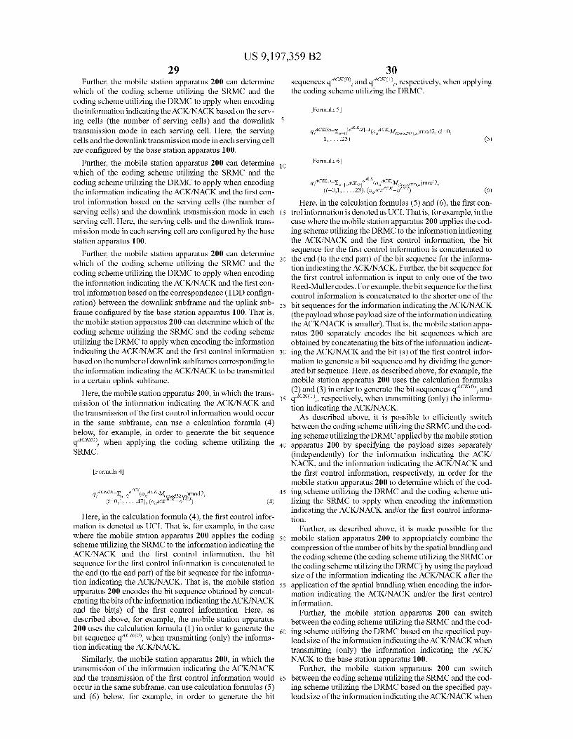
US 9, 197,359 B2 29
Further, the mobile station apparatus 200 can determine which of the coding scheme utilizing the SRMC and the coding scheme utilizing the DRMC to apply when encoding the information indicating the ACK/NACK based on the serv ing cells (the number of serving cells) and the downlink transmission mode in each serving cell. Here, the serving cells and the downlink transmission mode in each serving cell are configured by the base station apparatus 100.
Further, the mobile station apparatus 200 can determine which of the coding scheme utilizing the SRMC and the coding scheme utilizing the DRMC to apply when encoding the information indicating the ACK/NACK and the first con trol information based on the serving cells (the number of serving cells) and the downlink transmission mode in each serving cell. Here, the serving cells and the downlink trans mission mode in each serving cell are configured by the base station apparatus 100.
Further, the mobile station apparatus 200 can determine which of the coding scheme utilizing the SRMC and the coding scheme utilizing the DRMC to apply when encoding the information indicating the ACK/NACK and the first con trol information based on the correspondence (TDD configu ration) between the downlink subframe and the uplink sub frame configured by the base station apparatus 100. That is, the mobile station apparatus 200 can determine which of the coding scheme utilizing the SRMC and the coding scheme utilizing the DRMC to apply when encoding the information indicating the ACK/NACK and the first control information based on the number of downlink Subframes corresponding to the information indicating the ACK/NACK to be transmitted in a certain uplink Subframe.
Here, the mobile station apparatus 200, in which the trans mission of the information indicating the ACK/NACK and the transmission of the first control information would occur in the same Subframe, can use a calculation formula (4) below, for example, in order to generate the bit sequence q'', when applying the coding scheme utilizing the SRMC.
Formula 4
d4 Co-y, "co, CKM, )mod2, (=0,1, ... 47), (olcrack o'c) (4)
Here, in the calculation formula (4), the first control infor mation is denoted as UCI. That is, for example, in the case where the mobile station apparatus 200 applies the coding scheme utilizing the SRMC to the information indicating the ACK/NACK and the first control information, the bit sequence for the first control information is concatenated to the end (to the end part) of the bit sequence for the informa tion indicating the ACK/NACK. That is, the mobile station apparatus 200 encodes the bit sequence obtained by concat enating the bits of the information indicating the ACK/NACK and the bit(s) of the first control information. Here, as described above, for example, the mobile station apparatus 200 uses the calculation formula (1) in order to generate the bit sequence q“*”, when transmitting (only) the informa tion indicating the ACK/NACK.
Similarly, the mobile station apparatus 200, in which the transmission of the information indicating the ACK/NACK and the transmission of the first control information would occur in the same subframe, can use calculation formulas (5) and (6) below, for example, in order to generate the bit
5
10
15
25
30
35
40
45
50
55
60
65
30 ACKCO) Sequences q , and q'', respectively, when applying
the coding scheme utilizing the DRMC.
Formula 5
1, . . . .23) (5)
Formula 6
ACK q;'''-X, ACK2 (o,":Meis2)mod2. (i=0,1, ... 23), (oACK C*=oC) (6)
Here, in the calculation formulas (5) and (6), the first con trol information is denoted as UCI. That is, for example, in the case where the mobile station apparatus 200 applies the cod ing scheme utilizing the DRMC to the information indicating the ACK/NACK and the first control information, the bit sequence for the first control information is concatenated to the end (to the end part) of the bit sequence for the informa tion indicating the ACK/NACK. Further, the bit sequence for the first control information is input to only one of the two Reed-Muller codes. For example, the bit sequence for the first control information is concatenated to the shorter one of the bit sequences for the information indicating the ACK/NACK (the payload whose payload size of the information indicating the ACK/NACK is smaller). That is, the mobile station appa ratus 200 separately encodes the bit sequences which are obtained by concatenating the bits of the information indicat ing the ACK/NACK and the bit (s) of the first control infor mation to generate a bit sequence and by dividing the gener ated bit sequence. Here, as described above, for example, the mobile station apparatus 200 uses the calculation formulas (2) and (3) in order to generate the bit sequences q“*”, and q'*'', respectively, when transmitting (only) the informa tion indicating the ACK/NACK. As described above, it is possible to efficiently switch
between the coding scheme utilizing the SRMC and the cod ing scheme utilizing the DRMC applied by the mobile station apparatus 200 by specifying the payload sizes separately (independently) for the information indicating the ACK/ NACK, and the information indicating the ACK/NACK and the first control information, respectively, in order for the mobile station apparatus 200 to determine which of the cod ing scheme utilizing the DRMC and the coding scheme uti lizing the SRMC to apply when encoding the information indicating the ACK/NACK and/or the first control informa tion.
Further, as described above, it is made possible for the mobile station apparatus 200 to appropriately combine the compression of the number of bits by the spatial bundling and the coding scheme (the coding scheme utilizing the SRMC or the coding scheme utilizing the DRMC) by using the payload size of the information indicating the ACK/NACK after the application of the spatial bundling when encoding the infor mation indicating the ACK/NACK and/or the first control information.
Further, the mobile station apparatus 200 can switch between the coding scheme utilizing the SRMC and the cod ing scheme utilizing the DRMC based on the specified pay load size of the information indicating the ACK/NACK when transmitting (only) the information indicating the ACK/ NACK to the base station apparatus 100.
Further, the mobile station apparatus 200 can switch between the coding scheme utilizing the SRMC and the cod ing scheme utilizing the DRMC based on the specified pay load size of the information indicating the ACK/NACK when

US 9, 197,359 B2 31
transmitting both the information indicating the ACK/NACK and the first control information to the base station apparatus 1OO.
Further, the mobile station apparatus 200 can switch between the coding scheme utilizing the SRMC and the cod ing scheme utilizing the DRMC based on the sum of the specified payload size of the information indicating the ACK/ NACK and the payload size of the first control information when transmitting both the information indicating the ACK/ NACK and the first control information to the base station apparatus 100.
In the present embodiment, it is mainly described that the mobile station apparatus 200 encodes the uplink control information (the information indicating the ACK/NACK, the scheduling request, the channel state information) using the base sequence of the RM code to which the bit sequence of 11 bits can be input. However, it is obvious that the same embodiment can also be applied even in the case where the mobile station apparatus 200 uses a base sequence of the RM code to which any number of bits can be input. The embodiment explained above is also applied to the
integrated circuit mounted on the base station apparatus 100 and the mobile station apparatus 200. Further, in the embodi ment explained above, it can also be possible to control the base station apparatus 100 and the mobile station apparatus 200 by recording programs to implement each function of the base station apparatus 100 and each function of the mobile station apparatus 200 to a computer-readable recording medium and causing a computer system to read and execute the programs recorded in the recording medium. It is assumed that the “computer system” referred to here includes an OS and hardware, such as a peripheral.
Further, the “computer-readable recording medium” refers to a storage device, such as a portable medium Such as a flexible disc, a magneto-optical disc, a ROM, and a CD ROM, and a hard disc incorporated in the computer system. Further, it is supposed that the “computer-readable recording medium' includes those which dynamically hold programs for a brief time, such as a communication line in the case where programs are transmitted via a network, such as the Internet, and a communication circuit line. Such as a tele phone circuit line, and those which hold programs for a fixed period of time. Such as a nonvolatile memory within the computer system, which serves as a server or client in the above case. The above-mentioned programs can be those which implement part of the functions described previously, or may be those that can be implemented by combining the functions described previously and the programs already recorded in the computer system. As above, the embodiment of the invention is described in
detail with reference to the drawings, but, specific configura tions are not limited to the embodiment and designs etc. in the Scope not deviating from the gist of the present invention are also included in the scope of claims.
DESCRIPTION OF SYMBOLS
100 base station apparatus 101 data control portion 102 transmission data modulation portion 103 radio portion 104 scheduling portion 105 channel estimation portion 106 reception data demodulation portion 107 data extraction portion 108 higher layer 109 antenna
10
15
25
30
35
40
45
50
55
60
65
32 110 radio resource control portion 200, 200-1 to 200-3 mobile station apparatus 201 data control portion 202 transmission data modulation portion 203 radio portion 204 scheduling portion 205 channel estimation portion 206 reception data demodulation portion 207 data extraction portion 208 higher layer 209 antenna 210 radio resource control portion
The invention claimed is: 1. A mobile station apparatus configured to communicate
with a base station apparatus on a plurality of serving cells, the mobile station apparatus comprising:
a determining unit configured to determine a number of bits of HARQ information based on a number of down link Subframes corresponding to an uplink subframe in which the HARQ information is transmitted, a number of serving cells configured, and a transmission mode configured in each serving cell;
an applying unit configured to apply spatial bundling to the HARO information in a case where the determined num ber of bits of the HARQ information exceeds a prede termined value; and
a coding unit configured to select one of a first coding Scheme and a second coding scheme based on the num ber of bits of the HARQ information to which the spatial bundling has been applied and a number of bits of a scheduling request, and to encode both the HARQ infor mation and the scheduling request using the selected coding scheme, wherein
the first coding scheme is a method for encoding a bit sequence obtained by concatenating the bits of the HARO information and the bits of the scheduling request, and
the second coding scheme is a method for separately encoding respective bit sequences which are obtained by dividing a bit sequence, the bit sequence is generated by concatenating the bits of the HARQ information and the bits of the scheduling request.
2. The mobile station apparatus according to claim 1, wherein
the spatial bundling applied to the HARQ information includes processing to performan AND operation on the bits of the HARQ information corresponding to each of a first code word and a second code word, of a physical downlink shared channel in each downlink subframe on each serving cell.
3. The mobile station apparatus according to claim 1, wherein
the HARQ information is information indicating a positive acknowledgement (ACK) or a negative acknowledg ment (NACK) for a downlink transport block.
4. A processing methodofa mobile station apparatus that is configured to communicate with a base station apparatus on a plurality of serving cells, the processing method comprising:
determining a number of bits of HARQ information based on a number of downlink subframes corresponding an uplink subframe in which the HARQ information is transmitted, a number of serving cells configured, and a transmission mode configured in each serving cell;
applying spatial bundling to the HARO information in a case where the determined number of bits of the HARQ information exceeds a predetermined value; and

US 9, 197,359 B2 33
Selecting one of a first coding scheme and a second coding scheme based on the number of bits of the HARQ infor mation to which the spatial bundling has been applied and a number of bits of a scheduling request, and encod ing both the HARQ information and the scheduling 5 request using the selected coding scheme, wherein
the first coding scheme is a method for encoding a bit sequence obtained by concatenating the bits of the HARQ information and the bits of the scheduling request, and 10
the second coding scheme is a method for separately encoding respective bit sequences which are obtained by dividing a bit sequence, the bit sequence is generated by concatenating the bits of the HARQ information and the bits of the scheduling request. 15
5. The processing method according to claim 4, wherein the spatial bundling applied to the HARQ information
includes processing to performan AND operation on the bits of the HARQ information corresponding to each of a first code word and a second code word, of a physical 20 downlink shared channel in each downlink subframe in each serving cell.
6. The processing method according to claim 4, wherein the HARQ information is information indicating a positive
acknowledgment (ACK) or a negative acknowledgment 25 (NACK) for a downlink transport block.
7. An integrated circuit mounted on a mobile station appa ratus that is configured to communicate with a base station apparatus in on plurality of serving cells, the integrated circuit being able to perform and/or execute functions of: 30
determining a number of bits of HARQ information based on a number of downlink subframes corresponding to an uplink subframe in which the HARQ information is
34 transmitted, a number of serving cells configured, and a transmission mode configured in each serving cell;
applying spatial bundling to the HARQ information in a case where the determined number of bits of the HARQ information exceeds a predetermined value; and
Selecting one of a first coding scheme and a second coding scheme based on the number of bits of the HARQ infor mation to which the spatial bundling has been applied and a number of bits of a scheduling request, and coding both the HARQ information and the scheduling request using the selected coding scheme, wherein
the first coding scheme is a method for encoding a bit sequence obtained by concatenating the bits of the HARQ information and the bits of the scheduling request, and
the second coding scheme is a method for separately encoding respective bit sequences which are obtained by dividing a bit sequence, the bit sequence is generated by concatenating the bits of the HARQ information and the bits of the scheduling request.
8. The integrated circuit according to claim 7, wherein the spatial bundling applied to the HARQ information
includes processing to performan AND operation on the bits of the HARQ information corresponding to each of a first code word and a second code word, of a physical downlink shared channel in each downlink subframe in each serving cell.
9. The integrated circuit according to claim 7, wherein the HARQ information is information indicating a positive
acknowledgment (ACK) or a negative acknowledgment (NACK) for a downlink transport block.
Related Documents