12 SPRAYS 12.1 INTRODUCTION Sprays are an important constituent of many natural and technological pro- cesses and range in scale from the very large dimensions of the global air-sea interaction and the dynamics of spillways and plunge pools to the smaller dimensions of fuel injection and ink jet systems. In this chapter we first ex- amine the processes by which sprays are formed and some of the resulting features of those sprays. Then since, the the combustion of liquid fuels in droplet form constitute such an important component of our industrialized society, we focus on the evaporation and combustion of single droplets and follow that with an examination of the features involved in the combustion of sprays. 12.2 TYPES OF SPRAY FORMATION In general, sprays are formed when the interface between a liquid and a gas becomes deformed and droplets of liquid are generated. These then migrate out into the body of the gas. Sometimes the gas plays a negligible role in the kinematics and dynamics of the droplet formation process; this simplifies the analyses of the phenomena. In other circumstances the gasdynamic forces generated can play an important role. This tends to occur when the relative velocity between the gas and the liquid becomes large as is the case, for example, with hurricane-generated ocean spray. Several prototypical flow geometries are characteristic of the natural and technological circumstances in which spray formation is important. The first prototypical geometry is the flow of a gas over a liquid surface. When the relative velocity is sufficiently large, the interfacial shear stress produces waves on the interface and the breakup of the waves generates a spray that 285

Welcome message from author
This document is posted to help you gain knowledge. Please leave a comment to let me know what you think about it! Share it to your friends and learn new things together.
Transcript

12
SPRAYS
12.1 INTRODUCTION
Sprays are an important constituent of many natural and technological pro-cesses and range in scale from the very large dimensions of the global air-seainteraction and the dynamics of spillways and plunge pools to the smallerdimensions of fuel injection and ink jet systems. In this chapter we first ex-amine the processes by which sprays are formed and some of the resultingfeatures of those sprays. Then since, the the combustion of liquid fuels indroplet form constitute such an important component of our industrializedsociety, we focus on the evaporation and combustion of single droplets andfollow that with an examination of the features involved in the combustionof sprays.
12.2 TYPES OF SPRAY FORMATION
In general, sprays are formed when the interface between a liquid and a gasbecomes deformed and droplets of liquid are generated. These then migrateout into the body of the gas. Sometimes the gas plays a negligible role in thekinematics and dynamics of the droplet formation process; this simplifies theanalyses of the phenomena. In other circumstances the gasdynamic forcesgenerated can play an important role. This tends to occur when the relativevelocity between the gas and the liquid becomes large as is the case, forexample, with hurricane-generated ocean spray.
Several prototypical flow geometries are characteristic of the natural andtechnological circumstances in which spray formation is important. The firstprototypical geometry is the flow of a gas over a liquid surface. When therelative velocity is sufficiently large, the interfacial shear stress produceswaves on the interface and the breakup of the waves generates a spray that
285
is transported further into the gas phase by the turbulent motions. Oceanspray generated in high wind conditions falls into this category as doesannular, vertical two-phase flow. In some fuel injectors a coflowing gas jet isoften added to enhance spray formation. Section 12.4.2 provides an overviewof this class of spray formation processes.
A second, related configuration is a liquid pool or ocean into which gas isinjected so that the bubbles rise up to break through the free surface of theliquid. In the more quiescent version of this configuration, the spray is formedby process of break-through (see section 12.4.1). However, as the superficialgas flux is increased, the induced liquid motions become more violent andspray is formed within the gas bubbles. This spray is then released when thebubbles reach the surface. An example of this is the spray contained withinthe gas phase of churn-turbulent flow in a vertical pipe.
A third configuration is the formation of a spray due to condensation ina vapor flow. This process is governed by a very different set of physicalprinciples. The nucleation mechanisms involved are beyond the scope of thisbook.
The fourth configuration is the break up of a liquid jet propelled througha nozzle into a gaseous atmosphere. The unsteady, turbulent motions inthe liquid (or the gas) generate ligaments of liquid that project into thegas and the breakup of these ligaments creates the spray. The jet may belaminar or turbulent when it leaves the nozzle and the details of ligamentformation, jet breakup and spray formation are somewhat different in thetwo cases. Sections 12.4.3 and 12.4.4 will summarize the processes of thisflow configuration.
One area in which sprays play a very important role is in the combustionof liquid fuels. We conclude this chapter with brief reviews of the impor-tant phenomena associated with the combustion of sprays, beginning withthe evaporation of droplets and concluding with droplet and droplet cloudcombustion.
12.3 OCEAN SPRAY
Before proceeding with the details of the formation of spray at a liquid/gasinterface, a few comments are in order regarding the most widely studiedexample, namely spray generation on the ocean surface. It is widely acceptedthat the mixing of the two components, namely air and water, at the oceansurface has important consequences for the global environment (see, for ex-ample, Liss and Slinn, 1983, or Kraus and Businger, 1994). The heat and
286
mass exchange processes that occur as a result of the formation of bubbles inthe ocean and of droplets in the atmosphere are critical to many importantglobal balances, including the global balances of many gases and chemicals.For example, the bubbles formed by white caps play an important role inthe oceanic absorption of carbon dioxide; on the other side of the interfacethe spray droplets form salt particles that can be carried high into the atmo-sphere. They, in turn, are an important contributor to condensation nuclei.Small wonder, then, that ocean surface mixing, the formation of bubbles anddroplets, have been extensively studied (see for example Monahan and VanPatten, 1989). But the mechanics of these processes are quite complicated,involving as they do, not only the complexity of wave formation and break-ing but the dynamics of turbulence in the presence of free surfaces. This, inturn, may be affected by free surface contamination or dissolved salts be-cause these effect the surface tension and other free surface properties. Thus,for example, the bubble and droplet size distributions formed in salt waterare noticeably different from those formed in fresh water (Monahan andZietlow, 1969). Here, we shall not attempt a comprehensive review of thisextensive literature but confine ourselves to some of the basic mechanicalprocesses that are believed to influence these oceanic phenomena.
There appears to be some general concensus regarding the process of sprayformation in the ocean (Blanchard, 1983, Monahan, 1989). This holds that,at relatively low wind speeds, the dominant droplet spray is generated bybubbles rising to breach the surface. The details of the droplet formationprocess are described in greater detail in the next section. The most prolificsource of bubbles are the white caps that can cover up to 10% of the oceansurface (Blanchard, 1963). Consequently, an understanding of the dropletformation requires an understanding of bubble formation in breaking waves;this, in itself, is a complex process as illustrated by Wood (1991). What isless clear is the role played by wind shear in ocean spray formation (seesection 12.4.2).
Monahan (1989) provides a valuable survey and rough quantification ofocean spray formation, beginning with the white cap coverage and proceed-ing through the bubble size distributions to some estimate of the spraysize distribution. Of course, the average droplet size decays with elevationabove the surface as the larger droplets settle faster; thus, for example, deLeeuw (1987) found the average droplet diameter at a wind speed of 5.5m/sdropped from 18μm at an elevation of 2m to 15μm at 10m elevation. Thesize also increases with increasing wind speed due to the greater turbulentvelocities in the air.
287

Figure 12.1. Stages of a bubble breaking through a free surface.
Figure 12.2. Photographs by Blanchard (1963) of a bubble breakingthrough a free surface. Reproduced with permission of the author.
It is also important to observe that there are substantial differences be-tween spray formation in the ocean and in fresh water. The typical bubblesformed by wave breaking are much smaller in the ocean though the totalbubble volume is similar (Wang and Monahan, 1995). Since the bubble sizedetermines the droplet size created when the bubble bursts through thesurface, it follows that the spray produced in the ocean has many more,smaller droplets. Moreover, the ocean droplets have a much longer lifetime.Whereas fresh water droplets evaporate completely in an atmosphere withless than 100% relative humidity, salt water droplets increase their salin-ity with evaporation until they reach equilibrium with their surroundings.Parenthetically, it is interesting to note that somewhat similar differenceshave been observed between cavitation bubbles in salt water and fresh wa-ter (Ceccio et al. 1997); the bubbles in salt water are smaller and morenumerous.
12.4 SPRAY FORMATION
12.4.1 Spray formation by bubbling
When gas bubbles rise through a pool of liquid and approach the free surface,the various violent motions associated with the break through to the covergas generate droplets that may persist in the cover gas to constitute a spray.
288
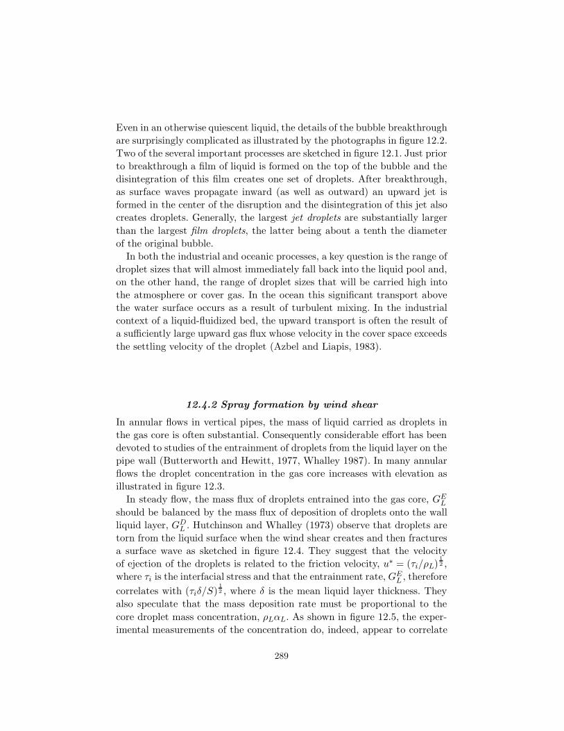
Even in an otherwise quiescent liquid, the details of the bubble breakthroughare surprisingly complicated as illustrated by the photographs in figure 12.2.Two of the several important processes are sketched in figure 12.1. Just priorto breakthrough a film of liquid is formed on the top of the bubble and thedisintegration of this film creates one set of droplets. After breakthrough,as surface waves propagate inward (as well as outward) an upward jet isformed in the center of the disruption and the disintegration of this jet alsocreates droplets. Generally, the largest jet droplets are substantially largerthan the largest film droplets, the latter being about a tenth the diameterof the original bubble.
In both the industrial and oceanic processes, a key question is the range ofdroplet sizes that will almost immediately fall back into the liquid pool and,on the other hand, the range of droplet sizes that will be carried high intothe atmosphere or cover gas. In the ocean this significant transport abovethe water surface occurs as a result of turbulent mixing. In the industrialcontext of a liquid-fluidized bed, the upward transport is often the result ofa sufficiently large upward gas flux whose velocity in the cover space exceedsthe settling velocity of the droplet (Azbel and Liapis, 1983).
12.4.2 Spray formation by wind shear
In annular flows in vertical pipes, the mass of liquid carried as droplets inthe gas core is often substantial. Consequently considerable effort has beendevoted to studies of the entrainment of droplets from the liquid layer on thepipe wall (Butterworth and Hewitt, 1977, Whalley 1987). In many annularflows the droplet concentration in the gas core increases with elevation asillustrated in figure 12.3.
In steady flow, the mass flux of droplets entrained into the gas core, GEL
should be balanced by the mass flux of deposition of droplets onto the wallliquid layer, GD
L . Hutchinson and Whalley (1973) observe that droplets aretorn from the liquid surface when the wind shear creates and then fracturesa surface wave as sketched in figure 12.4. They suggest that the velocityof ejection of the droplets is related to the friction velocity, u∗ = (τi/ρL)
12 ,
where τi is the interfacial stress and that the entrainment rate, GEL , therefore
correlates with (τiδ/S)12 , where δ is the mean liquid layer thickness. They
also speculate that the mass deposition rate must be proportional to thecore droplet mass concentration, ρLαL. As shown in figure 12.5, the exper-imental measurements of the concentration do, indeed, appear to correlate
289

with (τiδ/S)12 (a typical square root dependence is shown by the solid line
in the figure).McCoy and Hanratty (1977) review the measurements of the deposi-
tion mass flux, GDL , and the gas core concentration, ρLαL, and show that
the dimensionless deposition mass transfer coefficient, GDL /ρLαLu
∗, cor-relates with a dimensionless relaxation time for the droplets defined byD2ρLρGu
∗2/18μ2G. This correlation is shown in figure 12.6 and, for a given
u∗, can also be considered as a graph with the resulting droplet size, D (or
Figure 12.3. Droplet concentration profiles in the gas core of a verticalannular pipe flow (3.2cm diameter) illustrating the increase with elevationfrom initiation (lowest line, 15cm elevation; uppermost line, 531cm eleva-tion) (from Gill et al. 1963).
Figure 12.4. Sketch illustrating the ejection of droplets by wind shear inannular flow in a vertical pipe. From Hutchinson and Whalley (1973).
290
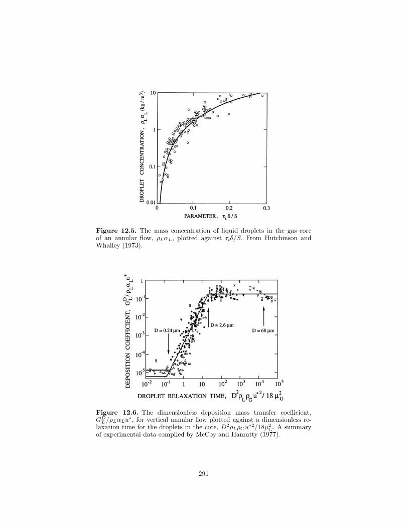
Figure 12.5. The mass concentration of liquid droplets in the gas coreof an annular flow, ρLαL, plotted against τiδ/S. From Hutchinson andWhalley (1973).
Figure 12.6. The dimensionless deposition mass transfer coefficient,GD
L /ρLαLu∗, for vertical annular flow plotted against a dimensionless re-
laxation time for the droplets in the core, D2ρLρGu∗2/18μ2
G. A summaryof experimental data compiled by McCoy and Hanratty (1977).
291
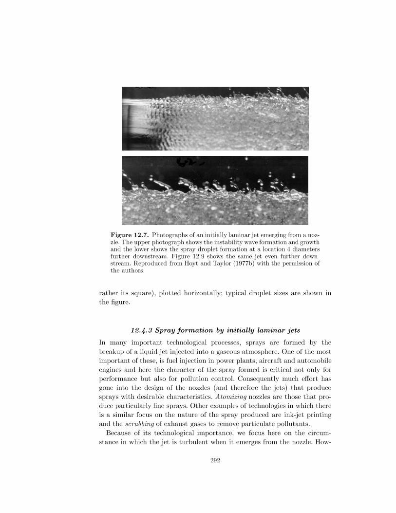
Figure 12.7. Photographs of an initially laminar jet emerging from a noz-zle. The upper photograph shows the instability wave formation and growthand the lower shows the spray droplet formation at a location 4 diametersfurther downstream. Figure 12.9 shows the same jet even further down-stream. Reproduced from Hoyt and Taylor (1977b) with the permission ofthe authors.
rather its square), plotted horizontally; typical droplet sizes are shown inthe figure.
12.4.3 Spray formation by initially laminar jets
In many important technological processes, sprays are formed by thebreakup of a liquid jet injected into a gaseous atmosphere. One of the mostimportant of these, is fuel injection in power plants, aircraft and automobileengines and here the character of the spray formed is critical not only forperformance but also for pollution control. Consequently much effort hasgone into the design of the nozzles (and therefore the jets) that producesprays with desirable characteristics. Atomizing nozzles are those that pro-duce particularly fine sprays. Other examples of technologies in which thereis a similar focus on the nature of the spray produced are ink-jet printingand the scrubbing of exhaust gases to remove particulate pollutants.
Because of its technological importance, we focus here on the circum-stance in which the jet is turbulent when it emerges from the nozzle. How-
292

ever, in passing, we note that the breakup of laminar jets may also be ofinterest. Two photographs of initially laminar jets taken by Hoyt and Tay-lor (1977a,b) are reproduced in figure 12.7. Photographs such as the upperone clearly show that transition to turbulence occurs because the interfaciallayer formed when the liquid boundary layer leaves the nozzle becomes un-stable. The Tollmein-Schlicting waves (remarkably two-dimensional) exhibita well-defined wavelength and grow to non-linear amplitudes at which theybreakup to form droplets in the gas. Sirignano and Mehring (2000) providea review of the extensive literature on linear and non-linear analyses of thestability of liquid jets, not only round jets but also planar and annular jets.The author (Brennen 1970) examined the development of interfacial insta-bility waves in the somewhat different context of cavity flows; this analysisdemonstrated that the appropriate length scale is the thickness of the in-ternal boundary layer, δ, on the nozzle walls at the point where the freesurface detaches. This is best characterized by the momentum thickness, δ2,though other measures of the boundary layer thickness have also been used.The stability analysis yields the most unstable wavelength for the Tollmein-Schlichting waves (normalized by δ2) as a function of the Reynolds numberof the interfacial boundary layer (based on the jet velocity and δ2). At largerReynolds number, the ratio of wavelength to δ2 reaches an asymptotic valueof about 25, independent of Reynolds number. Brennen (1970) and Hoyt andTaylor (1977a,b) observe that these predicted wavelengths are in accord withthose observed.
A natural extension of this analysis is to argue that the size of the dropletsformed by the non-linear breakup of the instability waves will scale with thewavelength of those waves. Indeed, the pictures of Hoyt and Taylor (1977a,b)exemplified by the lower photograph in figure 12.7 suggest that this is thecase. It follows that at higher Reynolds numbers, the droplet size shouldscale with the boundary layer thickness, δ2. Wu, Miranda and Faeth (1995)have shown that this is indeed the case for the initial drop formation ininitially nonturbulent jets.
Further downstream the turbulence spreads throughout the core of thejet and the subsequent jet breakup and droplet formation is then similar tothat of jets that are initially turbulent. We now turn to that circumstance.
12.4.4 Spray formation by turbulent jets
Because of the desirability in many technological contexts of nozzles thatproduce jets that are fully turbulent from the start, there has been extensivetesting of many nozzle designed with this objective in mind. Simmons (1977)
293
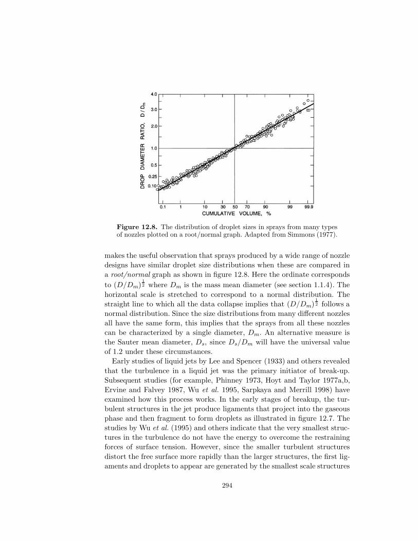
Figure 12.8. The distribution of droplet sizes in sprays from many typesof nozzles plotted on a root/normal graph. Adapted from Simmons (1977).
makes the useful observation that sprays produced by a wide range of nozzledesigns have similar droplet size distributions when these are compared ina root/normal graph as shown in figure 12.8. Here the ordinate correspondsto (D/Dm)
12 where Dm is the mass mean diameter (see section 1.1.4). The
horizontal scale is stretched to correspond to a normal distribution. Thestraight line to which all the data collapse implies that (D/Dm)
12 follows a
normal distribution. Since the size distributions from many different nozzlesall have the same form, this implies that the sprays from all these nozzlescan be characterized by a single diameter, Dm. An alternative measure isthe Sauter mean diameter, Ds, since Ds/Dm will have the universal valueof 1.2 under these circumstances.
Early studies of liquid jets by Lee and Spencer (1933) and others revealedthat the turbulence in a liquid jet was the primary initiator of break-up.Subsequent studies (for example, Phinney 1973, Hoyt and Taylor 1977a,b,Ervine and Falvey 1987, Wu et al. 1995, Sarpkaya and Merrill 1998) haveexamined how this process works. In the early stages of breakup, the tur-bulent structures in the jet produce ligaments that project into the gaseousphase and then fragment to form droplets as illustrated in figure 12.7. Thestudies by Wu et al. (1995) and others indicate that the very smallest struc-tures in the turbulence do not have the energy to overcome the restrainingforces of surface tension. However, since the smaller turbulent structuresdistort the free surface more rapidly than the larger structures, the first lig-aments and droplets to appear are generated by the smallest scale structures
294

Figure 12.9. A continuation from figure 12.7 showing two further views ofthe jet at 72 diameters (above) and 312 diameters (below) downstream fromthe nozzle. The latter illustrates the final breakup of the jet. Reproducedfrom Hoyt and Taylor (1977b) with the permission of the authors.
that are able to overcome surface tension. This produces small droplets. Butthese small structures also decay more rapidly with distance from the noz-zle. Consequently, further downstream progressively larger structures causelarger ligaments and droplets and therefore add droplets at the higher endof the size distribution. Finally, the largest turbulent structures comparablewith the jet diameter or width initiate the final stage of jet decompositionas illustrated in figure 12.9.
Wu, Miranda and Faeth (1995) utilized this understanding of the sprayformation and jet breakup process to create scaling laws of the phenomenon.With a view to generalizing the results to turbulent jets of other cross-sections, the radial integral length scale of the turbulence is denoted by 4Λwhere, in the case of round jets, Λ = dj/8, where dj is the jet diameter. Wuet al. (1995) then argue that the critical condition for the initial formation ofa droplet (the so-called primary breakup condition) occurs when the kineticenergy of a turbulent eddy of the critical size is equal to the surface energyrequired to form a droplet of that size. This leads to the following expression
295

Figure 12.10. The Sauter mean diameter, Dsi, of the initial dropletsformed (divided by the typical dimension of the jet, Λ) in turbulent roundjets as a function of the Weber number, We = ρLΛU2/S. The points are ex-perimental measurements for various liquids and jet diameters, dj. Adaptedfrom Wu et al. (1995).
for the Sauter mean diameter of the initial droplets, Dsi:
Dsi
Λ∝We−
35 (12.1)
where the Weber number, We = ρLΛU2, U being the typical or mean ve-locity of the jet. Figure 12.10 from Wu et al. (1995) demonstrates that datafrom a range of experiments with round jets confirm that Dsi/Λ does appearto be a function only of We and that the correlation is close to the formgiven in equation 12.1.
Wu et al. (1995) further argue that the distance, xi, from the nozzle to theplace where primary droplet formation takes place may be estimated usingan eddy convection velocity equal to U and the time required for Rayleighbreakup of a ligament having a diameter equal to the Dsi. This leads to
xi
Λ∝We−
25 (12.2)
and, as shown in figure 12.11, the data for different liquids and jet diametersare in rough accord with this correlation.
Downstream of the point where primary droplet formation occurs, pro-gressively larger eddies produce larger droplets and Wu et al. (1995) useextensions of their theory to generate the following expression for the Sauter
296

Figure 12.11. The ratio of the distance from the nozzle to the point whereturbulent breakup begins (divided by Λ) for turbulent round jets as a func-tion of the Weber number, We = ρLΛU2/S. The points are experimentalmeasurements for various liquids and jet diameters, dj . Adapted from Wuet al. (1995).
mean diameter, Ds, of the droplets formed at a distance, x, downstream ofthe nozzle:
Ds
Λ∝(
x
ΛWe12
)23
(12.3)
As shown in figure 12.12 the experimental measurements show fair agree-ment with this approximate theory.
Using this information, the evolution of the droplet size distribution withdistance from the nozzle can be constructed as follows. Assuming Simmonssize distributions, the droplet size distribution may be characterized by theSauter mean diameter, Ds. The primary breakup yields droplets character-ized by the initialDsi of equation 12.1. Then, moving downstream along thejet, contributions with progressively larger droplets are added until the jetfinally disintegrates completely.
Several footnotes should be added to this picture. First, the evolutiondescribed assumes that the gaseous phase plays a negligible role in the dy-namics. Wu and Faeth (1993) demonstrate that this will only be the casewhen ρL/ρG > 500. However this is frequently the case in practical applica-tions. Second, the above can be extended to other free jet geometries. Dai
297

Figure 12.12. The Sauter mean diameter, Ds (divided by Λ), of thedroplets formed at a distance, x, from the nozzle for turbulent round jetsfor various Weber numbers, We = ρLΛU2/S. The points are experimentalmeasurements for various liquids and jet diameters, dj. Adapted from Wuet al. (1995).
et al. (1998) demonstrate that the simple use of a hydraulic diameter allowsthe same correlations to be used for plane jets. On the other hand, wall jetsappear to follow different correlations presumably because the generationof vorticity in wall jets causes a different evolution of the turbulence thanoccurs in free jets (Dai et al. 1997, Sarpkaya and Merrill 1998). Sarpkayaand Merrill’s (1998) experiments with wall jets on horizontal smooth androughened walls exhibit a ligament formation process qualitatively similarto that of free jets. The droplets created by the ligament breakup have adiameter about 0.6 of the wall jet thickness and quite independent of Webernumber or plate roughness over the range tested.
Finally, the reader will note that the above characterizations are notablyincomplete since they do not address the issue of the total number or massof droplets produced at each stage in the process. Though this is crucialinformation in many technological contexts, it has yet to be satisfactorilymodeled.
298

12.5 SINGLE DROPLET MECHANICS
12.5.1 Single droplet evaporation
The combustion of liquid fuels in droplet form or of solid fuels in particulateform constitute a very important component of our industrialized society.Spray evaporation is important, in part because it constitutes the first stagein the combustion of atomized liquid fuels in devices such as industrial fur-naces, diesel engines, liquid rocket engines or gas turbines. Consequently themechanics of the evaporation and subsequent combustion have been exten-sively documented and studied (see, for example, Williams 1965, Glassman1977, Law 1982, Faeth 1983, Kuo 1986) and their air pollution consequencesexamined in detail (see, for example, Flagan and Seinfeld 1988). It is im-possible to present a full review of these subjects within the confines of thisbook, but it is important and appropriate to briefly review some of the basicmultiphase flow phenomena that are central to these processes.
An appropriate place to start is with evaporation of a single droplet in aquiescent environment and we will follow the description given in Flagan andSeinfeld (1988). Heat diffusing inward from the combustion zone, either onesurrounding a gas/droplet cloud or one located around an individual droplet,will cause the heating and evaporation of the droplet(s). It transpires thatit is adequate for most purposes to model single droplet evaporation as asteady state process (assuming the droplet radius is only varying slowly).Since the liquid density is much greater than the vapor density, the dropletradius, R, can be assumed constant in the short term and this permits asteady flow analysis in the surrounding gas. Then, since the outward flow oftotal mass and of vapor mass at every radius, r, is equal to mV and thereis no net flux of the other gas, conservation of total mass and conservationof vapor lead through equations 1.21 and 1.29 and Fick’s Law 1.37 to
mV
4π= ρur2 = ρ(u)r=RR
2 (12.4)
and
mV
4π= ρur2xV − ρr2D
dxV
dr(12.5)
where D is the mass diffusivity. These represent equations to be solved forthe mass fraction of the vapor, xV . Eliminating u and integrating produces
mV
4π= ρRD ln
(1 +
(xV )r=∞ − (xV )r=R
(xV )r=R − 1
)(12.6)
Next we examine the heat transfer in this process. The equation governing
299
the radial convection and diffusion of heat is
ρucpdT
dr=
1r2
d
dr
(r2k
dT
dr
)(12.7)
where cp and k are representative averages of, respectively, the specific heatat constant pressure and the thermal conductivity of the gas. Substitutingfor u from equation 12.4 this can be integrated to yield
mV cp(T +C) = 4πr2kdT
dr(12.8)
where C is an integration constant that is evaluated by means of the bound-ary condition at the droplet surface. The heat required to vaporize a unitmass of fuel whose initial temperature is denoted by Ti is clearly that re-quired to heat it to the saturation temperature, Te, plus the latent heat, L,or cs(Te − Ti) + L. The second contribution is usually dominant so the heatflux at the droplet surface can be set as:
4πR2k
(dT
dr
)r=R
= mV L (12.9)
Using this boundary condition, C can be evaluated and equation 12.8 furtherintegrated to obtain
mV
4π=Rk
cpln
{1 +
cp(Tr=∞ − Tr=R)L
}(12.10)
To solve for Tr=R and (xV )r=R we eliminate mV from equations 12.6 and12.10 and obtain
ρDcpk
ln
(1 +
(xV )r=∞ − (xV )r=R
(xV )r=R − 1
)= ln
(1 +
cp(Tr=∞ − Tr=R)L
)(12.11)
Given the transport and thermodynamic properties k, cp, L, and D (ne-glecting variations of these with temperature) as well as Tr=∞ and ρ, thisequation relates the droplet surface mass fraction, (xV )r=R, and temperatureTr=R. Of course, these two quantities are also connected by the thermody-namic relation
(xV )r=R =(ρV )r=R
ρ=
(pV )r=R
p
MV
M (12.12)
where MV and M are the molecular weights of the vapor and the mixture.Equation 12.11 can then be solved given the relation 12.12 and the saturatedvapor pressure pV as a function of temperature. Note that since the droplet
300
size does not occur in equation 12.11, the surface temperature is independentof the droplet size.
Once the surface temperature and mass fraction are known, the rate ofevaporation can be calculated from equation 12.7 by substituting mV =4πρLR
2dR/dt and integrating to obtain
R2 − (Rt=0)2 ={
2kcp
ln
(1 +
cp(Tr=∞ − Tr=R)L
)}t (12.13)
Thus the time required for complete evaporation, tev , is
tev = cpR2t=0
{2k ln
(1 +
cp(Tr=∞ − Tr=R)L
)}−1
(12.14)
This quantity is important in combustion systems. If it approaches the res-idence time in the combustor this may lead to incomplete combustion, afailure that is usually avoided by using atomizing nozzles that make theinitial droplet size, Rt=0, as small as possible.
Having outlined the form of the solution for an evaporating droplet, albeitin the simplest case, we now proceed to consider the combustion of a singledroplet.
12.5.2 Single droplet combustion
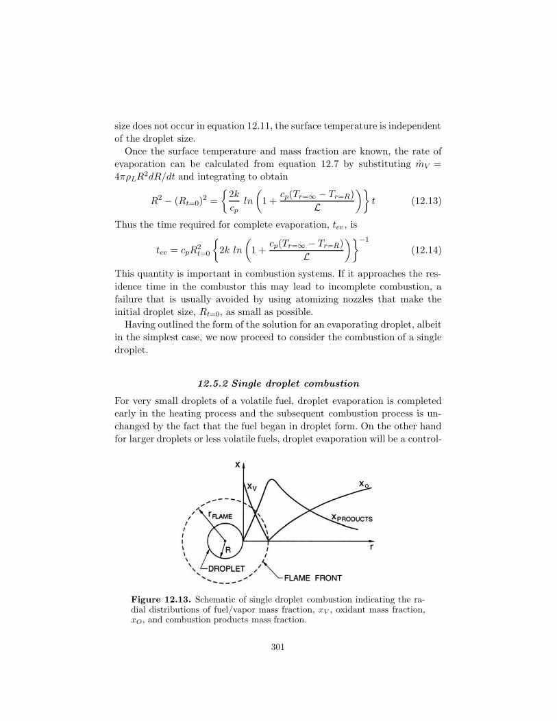
For very small droplets of a volatile fuel, droplet evaporation is completedearly in the heating process and the subsequent combustion process is un-changed by the fact that the fuel began in droplet form. On the other handfor larger droplets or less volatile fuels, droplet evaporation will be a control-
Figure 12.13. Schematic of single droplet combustion indicating the ra-dial distributions of fuel/vapor mass fraction, xV , oxidant mass fraction,xO, and combustion products mass fraction.
301

ling process during combustion. Consequently, analysis of the combustion ofa single droplet begins with the single droplet evaporation discussed in thepreceding section. Then single droplet combustion consists of the outwarddiffusion of fuel vapor from the droplet surface and the inward diffusionof oxygen (or other oxidant) from the far field, with the two reacting in aflame front at a certain radius from the droplet. It is usually adequate toassume that this combustion occurs instantaneously in a thin flame front ata specific radius, rflame, as indicated in figure 12.13. As in the last section, asteady state process will be assumed in which the mass rates of consumptionof fuel and oxidant in the flame are denoted by mV C and mOC respectively.For combustion stoichiometry we therefore have
mV C = νmOC (12.15)
where ν is the mass-based stoichiometric coefficient for complete combustion.Moreover the rate of heat release due to combustion will be QmV C whereQ is the combustion heat release per unit mass of fuel. Assuming the massdiffusivities for the fuel and oxidant and the thermal diffusivity (k/ρcp) areall the same (a Lewis number of unity) and denoted by D, the thermal andmass conservation equations for this process can then be written as:
mVdT
dr=
d
dr
(4πr2ρD
dT
dr
)+ 4πr2
QmV C
cp(12.16)
mVdxV
dr=
d
dr
(4πr2ρD
dxV
dr
)+ 4πr2mV C (12.17)
mVdxO
dr=
d
dr
(4πr2ρD
dxO
dr
)− 4πr2mOC (12.18)
where xO is the mass fraction of oxidant.Using equation 12.15 to eliminate the reaction rate terms these become
mVd
dr(cpT + QxV ) =
d
dr
(4πr2ρD
d
dr(cpT + QxV )
)(12.19)
mVd
dr(cpT + νQxO) =
d
dr
(4πr2ρD
d
dr(cpT + νQxO)
)(12.20)
mVd
dr(xV − νxO) =
d
dr
(4πr2ρD
d
dr(xV − νxO)
)(12.21)
Appropriate boundary conditions on these relations are (1) the droplet sur-
302

face heat flux condition 12.9, (2) zero droplet surface flux of non-fuel gasesfrom equations 12.4 and 12.5, (3) zero oxidant flux at the droplet surface,(4) zero oxidant mass fraction at the droplet surface (5) temperature at thedroplet surface, Tr=R, (6) known temperature far from the flame, Tr=∞, (7)zero fuel/vapor mass fraction far from the flame, (xV )r=∞ = 0, and (8) aknown oxidant mass fraction far from the flame, (xO)∞. Using these condi-tions equations 12.19, 12.20 and 12.21 may be integrated twice to obtain:
mV
4πρDr= ln
{cp(Tr=∞ − Tr=R) + L −Q
cp(T − Tr=R) + L −Q(1 − xV )
}(12.22)
mV
4πρDr= ln
{cp(Tr=∞ − Tr=R) + L + νQ(xO)r=∞
cp(T − Tr=R) + L + νQxO
}(12.23)
mV
4πρDr= ln
{1 + ν(xO)r=∞1 − xV + νxO
}(12.24)
and evaluating these expressions at the droplet surface leads to:
mV
4πρDR= ln
{cp(Tr=∞ − Tr=R) + L −Q
L−Q(1− (xV )r=R)
}(12.25)
mV
4πρDR= ln
{cp(Tr=∞ − Tr=R) + L + νQ(xO)r=∞
L}
(12.26)
mV
4πρDR= ln
{1 + ν(xO)r=∞1 − (xV )r=R
}(12.27)
and consequently the unknown surface conditions, Tr=R and (xV )r=R maybe obtained from the relations
1 + ν(xO)r=∞1 − (xV )r=R
=cp(Tr=∞ − Tr=R) + L + νQ(xO)r=∞
L
=cp(Tr=∞ − Tr=R) + L −Q
L−Q(1 − (xV )r=R)(12.28)
Having solved for these surface conditions, the evaporation rate, mV , wouldfollow from any one of equations 12.25 to 12.27. However a simple, ap-proximate expression for mV follows from equation 12.26 since the termcp(Tr=∞ − Tr=R) is generally small compared with Q(xV )r=R. Then
mV ≈ 4πRρD ln
(1 +
νQ(xO)r=∞L
)(12.29)
303

Figure 12.14. Droplet radius, R, and the ratio of the flame radius to thedroplet radius, rflame/R, for a burning octane droplet in a 12.5%O2, 87.5%N2, 0.15atm environment. Adapted from Law (1982).
The position of the flame front, r = rflame, follows from equation 12.27by setting xV = xO = 0:
rflame =mV
4πρD ln(1 + ν(xO)r=∞)≈ R
ln(1 + νQ(xO)r=∞/L)ln(1 + ν(xO)r=∞)
(12.30)
As one might expect, the radius of the flame front increases rapidly atsmall oxygen concentrations, (xO)∞, since this oxygen is quickly consumed.However, the second expression demonstrates that rflame/R is primarilya function of Q/L; indeed for small values of (xO)r=∞ it follows thatrflame/R ≈ Q/L. We discuss the consequences of this in the next section.
Detailed reviews of the corresponding experimental data on single dropletcombustion can be found in numerous texts and review articles includingthose listed above. Here we include just two sets of experimental results.Figure 12.14 exemplifies the data on the time history of the droplet ra-dius, R, and the ratio of the flame radius to the droplet radius, rflame/R.Note that after a small initial transient, R2 decreases quite linearly withtime as explicitly predicted by equation 12.13 and implicitly contained inthe combustion analysis. The slope, −d(R2)/dt, is termed the burning rateand examples of the comparison between the theoretical and experimentalburning rates are included in figure 12.15. The flame front location is alsoshown in figure 12.14; note that rflame/R is reasonably constant despite thefivefold shrinkage of the droplet.
Further refinements of this simple analysis can also be found in the texts
304

Figure 12.15. Theoretical and experimental burning rates, −d(R2)/dt (incm2/s), of various paraffin hydrocarbon droplets (R = 550μm) in a Tr=∞ =2530◦K environment with various mass fractions of oxygen, (xO)r=∞, asshown. Adapted from Faeth and Lazar (1971).
mentioned previously. A few of the assumptions that require further analysisinclude whether or not the assumed steady state is pertinent, whether rela-tive motion of the droplets through the gas convectively enhances the heatand mass transfer processes, the role of turbulence in modifying the heat andmass transfer processes in the gas, whether the chemistry can be modeledby a simple flame front, the complexity introduced by mixtures of liquids ofdifferent volatilities, and whether all the diffusivities can be assumed to besimilar.
12.6 SPRAY COMBUSTION
Now consider the combustion of a spray of liquid droplets. When the radiusof the flame front around individual droplets is small compared with the dis-tance separating the droplets, each droplet will burn on its own surroundedby a flame front. However, when rflame becomes comparable with the in-terdroplet separation the flame front will begin to surround a number ofdroplets and combustion will change to a form of droplet cloud combustion.Figure 12.16 depicts four different spray combustion scenarios as describedby Chiu and Croke (1981) (see also Kuo 1986). Since the ratio of the flamefront radius to droplet radius is primarily a function of the rate of the com-bustion heat release per unit mass of fuel to the latent heat of vaporizationof the fuel, or Q/L as demonstrated in the preceding section, these patternsof droplet cloud combustion occur in different ranges of that parameter. As
305

depicted in figure 12.16(a), at high values of Q/L, the flame front surroundsthe entire cloud of droplets. Only the droplets in the outer shell of this cloudare heated sufficiently to produce significant evaporation and the outer flowof this vapor fuels the combustion. At somewhat lower values of Q/L (figure12.16(b)) the entire cloud of droplets is evaporating but the flame front isstill outside the droplet cloud. At still lower values of Q/L (figure 12.16(c)),the main flame front is within the droplet cloud and the droplets in theouter shell beyond that main flame front have individual flames surround-ing each droplet. Finally at low Q/L values (figure 12.16(d)) every droplet issurrounded by its own flame front. Of course, several of these configurationsmay be present simultaneously in a particular combustion process. Figure12.17 depicts one such circumstance occuring in a burning spray emergingfrom a nozzle.
Note that though we have focused here on the combustion of liquid droplet
Figure 12.16. Four modes of droplet cloud combustion: (a) Cloud com-bustion with non-evaporating droplet core (b) Cloud combustion with evap-orating droplets (c) Individual droplet combustion shell (d) Single dropletcombustion. Adapted from Chiu and Croke (1981).
306

Figure 12.17. An example of several modes of droplet cloud combustionin a burning liquid fuel spray. Adapted from Kuo (1986).
sprays, the combustion of suspended solid particles is of equal importance.Solid fuels in particulate form are burned both in conventional boilers wherethey are injected as a dusty gas and in fluidized beds into which granular par-ticles and oxidizing gas are continuously fed. We shall not dwell on solid par-ticle combustion since the analysis is very similar to that for liquid droplets.Major differences are the boundary conditions at the particle surface wherethe devolatilization of the fuel and the oxidation of the char require specialattention (see, for example, Gavalas 1982, Flagan and Seinfeld 1988).
307
Related Documents