WBSETCL / TECH SPEC / Rev.-3 Page 1 of 30 12 KV VCB 12 KV, 25 KA, MULTI PANEL VACUUM CIRCUIT BREAKER January 2019 Engineering Department WEST BENGAL STATE ELECTRICITY TRANSMISSION COMPANY LIMITED Regd. Office: VidyutBhawan, Block – DJ, Sector-II, Bidhannagar, Kolkata – 700091. CIN: U40101WB2007SGC113474; Website: www.wbsetcl.in

Welcome message from author
This document is posted to help you gain knowledge. Please leave a comment to let me know what you think about it! Share it to your friends and learn new things together.
Transcript
WBSETCL / TECH SPEC / Rev.-3 Page 1 of 30 12 KV VCB
12 KV, 25 KA, MULTI
PANEL VACUUM
CIRCUIT BREAKER
January 2019
Engineering Department
WEST BENGAL STATE ELECTRICITY TRANSMISSION COMPANY LIMITED
Regd. Office: VidyutBhawan, Block – DJ, Sector-II, Bidhannagar, Kolkata – 700091. CIN: U40101WB2007SGC113474; Website: www.wbsetcl.in

WBSETCL / TECH SPEC / Rev.-3 Page 2of 30 12 KV VCB
1122 KKVV MMUULLTTII PPAANNEELL VVAACCUUUUMM CCIIRRCCUUIITT BBRREEAAKKEERR
SCOPE OFWORK
This Specification is intended to cover the design, manufacture, assembly, testing at
manufacturer‟s works, supply and delivery (properly packed for transport by road) of 12 KV,
1250/800A, 25 KA, Multi Panel, Shunt Trip, Indoor Type, Motor Operated, Spring Closing, Vacuum Circuit Breaker having SCADA Compatible facilities & complete with all accessories
for efficient and trouble free operation as specifiedhereinafter.
APPLICABLE STANDARDS
Unless otherwise stated, equipment shall be designed, constructed and tested in accordance with
latest revisions of following Indian Standards:
a) CircuitBreaker IS:13118-1991
b) PotentialTransformer IS:3156-1992
c) CurrentTransformers IS:2705-1992
d) Painting IS:5, Shade631
e) Other applicable relevant IndianStandards
EQUIPMENT & SERVICE
a) Multi-panel Vacuum Circuit Breaker shall consist of 12 kV, 25 kA Multi panels (Incoming, Bus Coupler and Outgoing) Shunt Trip, Indoor type Vacuum Circuit Breaker with SCADA
Compatiblefacilities (as per WBSETCL tech spec).
b) The equipment shall be complete with all necessary accessories and materials inaccordance with theSpecification.
c) The base channel frames for the switchgear for grouting in the floor shall be complete with anchor bolt, nuts and levelingattachment.
d) Special tools andtackles.
e) All relevant drawings, data and instructionmanuals.
DESIGN CRITERIA
The equipment will be located indoors in a clean but humid and tropical atmosphere.
For the purpose of designing, the following conditions shall be considered unless otherwise
specified :
a) Elevation above meansealevel 1000M
( For higher altitude supplier shall consider
altitude correction factor for the design of the equipment)

WBSETCL / TECH SPEC / Rev.-3 Page 3of 30 12 KV VCB
b) Maximum ambienttemperature - inshade 50ºC - undersun 60ºC
c) Maximum dailyaveragetemperature 45ºC
d) Minimum ambientairtemperature 4ºC
e) Relativehumidity 100%
f) Horizontal acceleration due toseismicforce 59/100
g) Maximumwindpressure 150Kg/m2
h) Pollutionlevel Heavily pollutedatmosphere
i) It may be mentioned that sites fall within Seismic zones III & IV classified as per
IS:1893-1984.
STANDARD TECHNICAL PARAMETERS
SL
DESCRIPTION
VALUES/ INFORMATIONS
1. Type of Switch Gear as per Arc Interrupter VCB
2. Frequency 50 c/s
3. Power Frequency withstand Voltage ( 1min) 28 KV rms
4. LI withstand Voltage ( 1.2 / 50 micro-sec) 75 kVp
5. Rated Current 800A / 1250 /1600A
6. Rated breaking current 25 KA
7. Rated Short Time Withstand Current for 3
sec - Symmetrical 25KArms
8. Rated Short Time Withstand Current for 3
sec - Asymmetrical
1.55 times of 25 KArms
9. Rated dynamic peak withstand current (KAp) 62.5 KA
10. Control Voltage 30/110/220Volts DC with
variation as per IS
A) RatedVoltage
The equipment shall be suitable generally for system of nominal voltage of 11000 Volts, 3 phase,
50 C/S, system may be effectively or non effectively earthed. Nominal voltage of the system where the equipment will be used may be taken as 11 kV (Phase to Phase), which shall be
subjected to a variation upto 13 kV (Phase to Phase) on the higher side for prolonged period of use. The rated voltage of equipment shall be considered as 12 kV.

WBSETCL / TECH SPEC / Rev.-3 Page 4of 30 12 KV VCB
B) RatedCurrent
The multi-panel Vacuum Circuit Breaker buses shall be rated for continuous current of 1250 /
1600 Amps for 12KV and maximum temperature rise of the bus and bus connection shall be limited as per provision in the IS. The Circuit Breaker unit shall be rated for continuous current of
1250 /1600 Amps for Buscoupler switchgear, 1250/800Amps for outgoing & incoming switchgear.
5.0 SPECIFICREQUIREMENT
a) General
The equipment shall be indoor, metal enclosed, floor mounted suitably isolated, Floor Level
horizontal draw-out Vacuum Circuit Breaker havingSCADA(as per WBSETCL tech spec ) Compatible facilities. Design and construction shall be such as to allow for extension at either end
in future.
b) Construction
Each board shall consist of stationary type, self-supporting sheet-steel cubicle and draw-out type
circuit breaker. The design and workmanship shall permit complete interchangeability of the circuit breaker unit among multi-panel board including incoming & outgoing feeder breaker and
bus coupler breaker andvice-versa.
The circuit breaker cubicle shall have structural steel frame work enclosed on all sides and top by sheet steel of minimum 2 mm thickness.
Overall height will be maximum 2700 mm. Overall width & depth will be maximum
710 mm. & 1950 mm respectively.
The cubicle shall be provided with a front access door with a removable back cover.
The circuit breaker, bus-bar, instrument transformer and cable end box shall be installed in
separate compartments within the cubicles.
The compartment shall be so constructed that failure of one equipment does not affect the adjacent units. Suitable vent shall be provided for satisfactory performance. Each compartment
shall be separated from adjacent one by sheet steel barrier. Offered equipment shall be type
tested against internal arc as per provision in IEC Publication No. 298: 1981.
Relays, meters, switches and lamps shall be flush mounted on the hinged front door of either the
cubicle itself or the control cabinet built on the front of the cubicle.
All fixing bolts, screws etc. appearing on the panel shall be so arranged as to present a neat appearance. Door hinges shall be concealed type.
Provision shall be made for sealing the following :
Potential transformers shall be provided with sealing arrangement by extension pieces, welded at
WBSETCL / TECH SPEC / Rev.-3 Page 4of 30 12 KV VCB
appropriate places of the potential transformer with stationary portion of equipment so that P.T.
cannot be displaced from its position when it is racked in position. The P.T. and secondary fuse units when fitted over the top of P.T. / Cubicle, shall be provided with sealing arrangement by a
common steel sheet of sufficient rigidity and with suitably hinged at one side, so that after the said fuse units are sealed, no part of the fuse grips and connections become accessible from
outside for displacement of the same.
The multi-way terminal block inside the cubicle where all the secondary leads from the CTs & PTs will terminate shall be covered with insulated transparent cover having suitable sealing
arrangement for preventing access to those terminals for manipulation of connections or loosening thesame.
Test terminal block of metering circuit shall be covered having suitable sealing arrangement.
c) Bus andBus-taps
The main bus of each section of Multi-Panel Board shall be of high conductivity electrolytic copper liberally sized for 1600A (as per requirement) .
The bus-end connections shall be so supported as to be capable to safely withstand stresses due
to maximum short circuit current and also to take care of any thermal expansion.
Three phase bus shall be adequately insulated for working voltage. For air insulated circuit breaker, bus-bar shall be provided with insulating sleeves and joints shall be provided with
insulated removable shrouds.
All bus connections, joints and taps shall be tinned or silver plated, Connections shall be as short & straight as possible.
Necessary provision shall be made for testing current transformer primary by removing insulated portion of the joints without any difficulty.
d) NamePlate
Name Plates of approved design shall be furnished at front and back of each cubicle for the
purpose of feeder designation.
Material for Nameplate shall be transparent plastic sheet of 3 mm thick and 25 mm x 150 mm
andshallbeheldbyselftappingscrewsandshallbefixedataconspicuousposition.
e) RatingPlate
Each unit shall be provided with a rating plate marked with the following :

WBSETCL / TECH SPEC / Rev.-3 Page 6of 30 12 KV VCB
Name of the Manufacturer and Year of Manufacture
Purchase Order Number and Date
Type, Designation & Serial Number
Rated Voltage and Current
Rated Frequency
Number of Poles
Rated Short Circuit Breaking Current
Rated Short Circuit Making Current
Short time Current for 1 sec.(kA)
3 sec. (kA)
Rated Insulation Level
Rated Operating sequence
Aux. Voltage (DC/AC)
Property Label - “Property of WBSETCL.”
f) PowerSupply
For multi-panel board the provision for external DC and AC supply has to be arranged in
Incoming and Bus Coupler Panels.
Contractor shall run bus wires for providing this power supply to different cubicles of multi-panel board. Isolating fuse units shall be provided for incoming supplies to each Switchgear Unit.
g) Secondary and SmallWiring
The Contractor shall furnish and install all wiring for the equipment & devices located on/ or within the board and wiring shall be complete in all respects so as to ensure proper function of control (i.e. protection, metering, indicating etc.)circuit.
Fuses shall be provided to enable individual circuits to be isolated from bus wires without
disturbing the other circuits. All wirings shall be done with flexible heat resistant switch board wires, PVC insulated with
standard copper conductor suitable for 660 Volts service. The sizes of wires in different circuits
shall not be less than those specified below:
Circuit Min. permissible
size of wire Metering and relaying circuits connected to current Transformers 4 sq.mm
Potential circuits for metering and relaying control, visual and audible alarm & signaling circuits
2.5 sq.mm
Main AC and DC Bus Wire 4.0 sq.mm
The wires shall be suitably grouped in bunches by non-metallic wiring cleat or bands with each
bunch adequately supported along its run to prevent sagging due to flexibility of vibration conforming to IS.
WBSETCL / TECH SPEC / Rev.-3 Page 7of 30 12 KV VCB
All wiring shall be done in such a way that it will have sufficient clearance from High Voltage
System. Other than L.T.P.T. fuse, no fuse shall be provided in the circuit carrying power from PT
secondary for metering purpose.
Sufficient bus wires shall be provided for inter connecting with adjacent units both ways and also
for future connection to additional units.
h) Circuit Breaker ClosingMechanism
The circuit breaker shall be provided with motor operated spring charged closing mechanism, anti-pumping relay and also with manually charged spring closing mechanism trip free nature.
Requisite hand operating device shall be supplied with multi-panel board equipment.
i) TerminalBlock
Multi-way terminal blocks complete with necessary binding screws & washers for wire
connections and marking strips for terminal identification shall be furnished for terminating cubicle wiring and outgoingcables.
The terminal block shall have at least 25% spare terminals.
The terminals shall be bolted type robust, rust-free and suitable for connection of at least 2 nos.
2.5 mm² copper wires per terminal.
Disconnecting type terminal block has to be used in CT PT Circuit.
j) CableTermination
HT Power Cable from LV side of power transformer shall enter in the rear bottom portion of
incoming breaker through 2 (Two) nos. rear entry cable end boxes, so double cable termination arrangement to be provided with 2 (Two) sets of nut & bolts.
HT Power Cable for distribution feeder shall enter in the rear bottom portion of outgoing breaker through rear entry cable end box.
HT Power Cable for connection to shunt capacitor bank or connection to another multi-panel switchgear shall enter in the multi-panel board equipment from side of the panel through right
angle side entry cable end box.
HT Power Cables shall be of standard 3 core XLPE type, 11 kV grade cable of Aluminum conductor.
Maximum sizes of HT Power Cables for connection to Incoming/ Outgoing Breaker will be as follows :
Voltage Grade
11000 Volts
Switchgear Designation
a) Incomer 2 nos.
Size
300 mm²
b) Outgoing 1 no. 300 mm²
Maximum size of cable for connection through right angle side entry cable end box will be 300 mm² for 11000 Volts system.

WBSETCL / TECH SPEC / Rev.-3 Page 8of 30 12 KV VCB
Normally no rear entry cable end box shall be supplied with the equipment unless otherwise required from design consideration. But provision shall be made for housing, fixing and covering
cable & cable end boxes in each incoming and outgoing switchgear panel.
However, rear entry cable end boxes shall have to be provided by the manufacturer for design consideration if cables remain exposed at the back side of the panel.
Normally 1 (one) no. right angle side entry cable end box shall be supplied with each multi-panel
shunt trip equipment for connection with bus bar of incoming breaker. Side entry cable end box shall be complete with tubular tinned copper lugs, armour clamp gland plate, brass gland for
termination and connection of HT Power Cable in air insulation with bus-bar of breaker through
flat tinned copper extension piece. The right angle side entry cable end box shall be supplied in detachable condition in a separate crate.
Multi-core cable terminal box shall be provided in easily associable suitable locations at the back
side of the panels for connecting multi-core Control Cables. External DC and AC supply arrangement to be provided in Incomer and Bus Coupler panel only in a switch board.
k) GroundBus
A grounding bus rated to carry maximum fault current shall be furnished along the full length of the panel board. Each stationary unit shall be grounded directly to the ground bus.
Connectors shall be provided at two ends for connection to user‟s ground conductor.
The frame of each circuit breaker shall be grounded through heavy multiple finger contacts at all times except when breaker primary disconnecting devices separated by a safe distance.
l) TropicalFinish
All electrical equipment, accessories & wiring shall have fungus protection involving special
treatment of insulation and metal against fungus, insect & corrosion. Screens shall be furnished on all ventilating covers to prevent entrance of foreign elements.
m) Painting
Modern method of painting like stove enameling or similar process as per provision in the Indian Standard shall be followed for painting all surfaces of panel, after the frame work is made free of
scale, rust, foreign adhering mater or grease.
After cleaning the surfaces shall be given a phosphate coating followed by a coat of high quality red oxide or yellow primer.
The equipment shall be finished in light gray with two coats of synthetic enamel paint or powder coating as per relevant ISS.
Sufficient quantity of touch-up paint shall be furnished for application at site.

WBSETCL / TECH SPEC / Rev.-3 Page 9of 30 12 KV VCB
6.0 SWITCHGEAREQUIPMENT
I) Circuit Breaker – Type &Rating
Circuit Breakersrated for continuous current of 1250 Amps shall be vacuum interrupting type. All
breaker units shall be physically and electrically interchangeable. The equipment shall be floor mounted and shall consist of stationary type, self-supporting sheet steel cubicles and draw out
type. The designation and workmanship shall permit complete interchangeability of truck assembly.
Each Circuit breaker (i.eIncommer, feeder & B/c) shall be provided with Mechanical „ON‟ & „OFF‟
facility by operating suitable closing and opening devices. Each breaker shall be provided with Mechanical „ON‟ & „OFF‟ indicators. Trip circuit healthy indication & spring charging indication are
to be provided. All the breaker shall be provided with motor operated spring charged closing mechanism, antipumping relay and also with manual operated spring charged mechanism & trip.
Spring charge limit switch shall have at least 4NO & 2NC contact.
Each breaker shall have (3) positions – service, isolated and withdrawal positions marked. Each breaker shall have mechanical indicators for spring “charged” and spring “discharged” conditions.
Mechanical safety interlocks shall be provided so that it is not possible for a circuit breaker :
To be put into the cubicle unless the truck is secured in position.
To be either raised or lowered from and to the service position unless its contacts are safely open.
To be withdrawn or inserted in the fixed housing unless it is at the withdraw able position.
To be operated in service position unless its primary and secondary isolating contacts are fully engaged.
Automatic safety shutters shall be provided to completely cover the female primary contacts,
which will be disconnected when the breaker is withdrawn. Bus-bar and feeder spout shutter screen be pad locked independently.
The circuit breaker racking equipment can be padlocked in any position.
Automatic tripping of the circuit breaker shall be effected by DC operated trip coil of voltage rating asspecified.
Each breaker shall be provided with electrical trip and close facility by using control switch.
Spring controlled switch with trip – neutral-close facility to be used. Electrical close and trip operation should be dependent on Local/Remote Switch. However protection trip and emergency
trip circuit should be independent of Local/RemoteSwitch.
Each breaker shall be provided with operation counter.
Vacuum interrupter for Vacuum Circuit Breaker shall be short time rated for minimum 25 kA for 100 nos. operations.

WBSETCL / TECH SPEC / Rev.-3 Page 10of 30 12 KV VCB
II) Bus CouplerBreaker
This will be a Vacuum Circuit Breaker for coupling two sections of buses. The Bus Coupler shall
berated for continuous current of 1250 Amps. It should be interchangeable with incomer andfeeders.
Bus coupler shall be floor mounted, vacuum interrupting and horizontal draw out type complete
with transfer trucks. The Bus coupler shall be provided with motor operated spring charged closing mechanism, anti-
pumping relay and also with manual operated spring closing mechanism & trip free nature. There shall not be any instrument meters.
III) CurrentTransformers
The Current Transformers shall be mounted on the rear side stationary portion of the unit and shall be easily accessible for maintenance and testing purpose. The method of securing Current
Transformer in position shall be such that no undue strain comes on the winding/ terminals.
The Current Transformers shall be capable of safely withstanding the stresses due to maximum short circuit current.
Each CT shall be rated to carry normal current as specified.
Current Transformer shall be free from absorption of moisture present in the air.
Universal type fixing arrangement shall be adopted for fixing all the Current Transformers irrespective of their use as incoming or outgoing, and shall be such that replacement of Current
Transformer by any other ratio can be done without any difficulty.
No resin casting/ compounding shall be allowed at the junction where CT primary terminals will
be connected at High Voltage Bus to facilitate easy replacement/ removal and testing of CT by way of primary injection at site without dismantling CT from theunit.
Secondary terminals of the CT shall be easily accessible to facilitate easy replacement/ removal and testing of CT at site without dismantling CT from the unit.
Primary and secondary terminals of the CT shall be marked properly as per provision in the
relevant standard. P1 side of CT should be in bus side in incoming and feeder breakers.
Secondary terminals should be in the P2 side of theCT.
CT shall be easily replaceable by only removing the back cover of the unit.
Each CT shall be provided with wiring diagram plate as per relevant provision of IS showing
primary and secondary terminals for connection at different ratio for metering & protection cores.
Each CT shall be provided with a rating plate legible and indelibly marked with following :
CT & PT Secondary Wiring should be connected in Terminal Board with round type socket only and properly crimped.
Three number Current Transformers shall be provided in each Incoming Breakers having following particulars:
i) Type : Triple core, Dual ratio, Resin cast, Indoortype
WBSETCL / TECH SPEC / Rev.-3 Page 11of 30 12 KV VCB
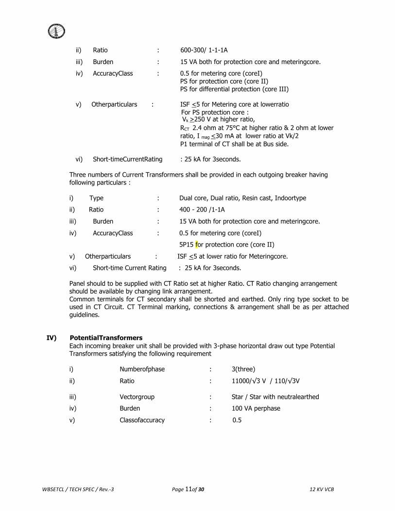
ii) Ratio : 600-300/ 1-1-1A
iii) Burden : 15 VA both for protection core and meteringcore.
iv) AccuracyClass : 0.5 for metering core (coreI)
PS for protection core (core II)
PS for differential protection (core III)
v) Otherparticulars : ISF <5 for Metering core at lowerratio
For PS protection core : Vk >250 V at higher ratio,
RCT 2.4 ohm at 75°C at higher ratio & 2 ohm at lower
ratio, I mag <30 mA at lower ratio at Vk/2 P1 terminal of CT shall be at Bus side.
vi) Short-timeCurrentRating : 25 kA for 3seconds.
Three numbers of Current Transformers shall be provided in each outgoing breaker having
following particulars :
i) Type : Dual core, Dual ratio, Resin cast, Indoortype
ii) Ratio : 400 - 200 /1-1A
iii) Burden : 15 VA both for protection core and meteringcore.
iv) AccuracyClass : 0.5 for metering core (coreI)
5P15 for protection core (core II)
v) Otherparticulars : ISF <5 at lower ratio for Meteringcore.
vi) Short-time Current Rating : 25 kA for 3seconds.
Panel should to be supplied with CT Ratio set at higher Ratio. CT Ratio changing arrangement should be available by changing link arrangement.
Common terminals for CT secondary shall be shorted and earthed. Only ring type socket to be used in CT Circuit. CT Terminal marking, connections & arrangement shall be as per attached
guidelines.
IV) PotentialTransformers
Each incoming breaker unit shall be provided with 3-phase horizontal draw out type Potential Transformers satisfying the following requirement
i) Numberofphase : 3(three)
ii) Ratio : 11000/√3 V / 110/√3V
iii) Vectorgroup : Star / Star with neutralearthed
iv) Burden : 100 VA perphase
v) Classofaccuracy : 0.5

WBSETCL / TECH SPEC / Rev.-3 Page 12of 30 12 KV VCB
vi) Protection of HV&LV : HRCFuses
vii) Overvoltagefactor : 1.2 for continuous & 1.9 for 8hrs
PT should be 3 Phase , 5 Limb with star connection. Star point should be earthed in HV &LV side.
PT shall be resin cast/ dry type and shall be suitable in our system conditions
Each PT shall be provided with Vector diagram plate as per relevant provision of IS showing primary and secondary terminals.
Each PT shall be provided with a rating plate legibly and indelibly marked.
The secondary circuit from all the PTs of the incoming panels shall be wired upto all the outgoing panels so that supply to the potential coils of the meters can be maintained from any of the PTs.
Plug & socket type contacts shall be provided in the PT secondary. PT secondary terminals shall be inaccessible from outside.
Necessary provision shall be made for sealing PT while at racked in position.
PT secondary fuse boxes shall be provided with sealing arrangement.
The Potential Transformer shall be mounted on rails on top of the unit and shall be connected on
the bus side. It can be plugged into and withdraw from service by pulling or pushing the PT by the handle provided on the PT. This action shall traverse the PT along the rails and shall
automatically operate the spout shutters. The shutter drive also forms a latch, which holds the PT
in the service position and this latch shall be required to be released before PT can be isolated.
The body earthing of PT shall be of permanent type and shall be so designed that it will remain
earthed by bolted connection both under rack-in and rack-out conditions. Use of flexible wire
netting will be perhaps most suitable for this purpose.
PT should be suitable for use in effectively and non-effectively earthed system.
V) Relays
b) NumericalNon-DirectionalOverCurrentandEarthFaultProtectionRelays
The primary requirements of the relays are to protect the respective feeders in the event of fault
and when installed in a standard board formation (i.e. incomers from transformer (s), outgoing feeders, bus-coupler (s) etc.) in a substation, the system should additionally provide busbar
protection facilities, interlocks between panels etc. The relays should be suitable for substation automation, primarily circuit breaker operation, through SCADA from remote Control Room.
The relay should have the following minimum specification / features and conforming to relevant IEC / IS.
1. Suitable for flush mounting on front panel of the switch cubicle to be installed in aindoor substation.
2. The relay should be suitable to function in non AC environment having wide temperature variation of 0 to 55˚C and relative humidity variation of 50 % to 100% throughout theyear
WBSETCL / TECH SPEC / Rev.-3 Page 14of 30 12 KV VCB
also in presence of electrostatic, electromagnetic and transients prevailing in high voltage
system.
3. Relays should be suitable for both 1A & 5A CT input which can be easily selectable at site and auxiliary DC supply of 30 /110/220V.
4. Relays should have the following features-
● The relay should be able to measure thefollowing: a) Three phase (Positive sequence)current.
b) Neutral (Zero sequence )current.
● 3 Nos independent time delayed over current stage and earth fault stage with IDMTL
(NI, VI. & EI) and D.T.Lcharacteristics. ● Noofindependentsettinggroup–2Nos.(canbechangedbyBinaryInput) ● Trip CircuitSupervision. ● Anti pumpingfeature,
● 1 main DC fail , 1 main AC fail , DC fail accept relay at buscopler panel ● Circuit Breaker failure protectionfunction.
● No of programmable LEDs - At least 4 Nos with latchingoptions.
● Should be able to record at least 5 oscillographic disturbances & 5 fault records and 250 event records . All recorded / stored events should have “Date & Time”. Tagged. Those recording
should be preserved in a non-volatilememory.
● Should have minimum 10 programmable optically isolated inputs, 10 Programmable outputs B/I & B/O and with latching options. Output contacts should be suitable for carrying close & trip
coil current. & 1 watchdog contact for supervision of healthiness of relay should also bethere.
● Should have the “Time Synchronisation” facility of its internal clock by means of pulsed through Binary Inputs or via station bus communication / GPSsignals. ● Shouldhavepasswordprotectedkeypadlockstoallowrelaysettingfromrelayfront.
● Should have comprehensive self diagnostic feature with remote indication of relay failureand
alarm shall be generated without tripping thecircuit. ● Cut out diagram for “Flush mounting type” relays are to be supplied in a separatesheet.
● The relay should be suitable for all operations required for SCADA ( as per WBSETCL
tech spec of CRP)and should also \ comply with the technical specification of theBreaker
5. Control of circuit breaker, supervision of status of spring ofC.B. status of C.B are also
required
Remote Monitoring
a) Suitable arrangement to be provided to monitor the breaker from remote at SCADAcontrol
end in case the following condition of 11KVVCBwith 20% spare facility i) DCHealthy
ii) AC healthy
iii) BreakerOFF
iv) BreakerON
v) Breaker inLocal
vi) Breaker inRemote
vii) Breaker inTest
viii) Breaker inService
ix) Breaker is antipumping operated
x) Spring for closing mechanismcharged
xi) Trip circuithealthy
xii) Tripping due toO/C
xiii) Tripping due toE/F
xiv) Trip relay operated
xv) Trip relay unhealthy

WBSETCL / TECH SPEC / Rev.-3 Page 14of 30 12 KV VCB
xvi)
Remote Closing
b) Suitable arrangement to be provided to close the breaker from remote at SCADA controlend
in case the following condition of 11KVVCB
i) DCHealthy ii) BreakerOFF
WBSETCL / TECH SPEC / Rev.-3 Page 15of 30 12 KV VCB
iii) Breaker inRemote iv) Breaker is not antipumping
v) Spring for closing mechanismcharged
vi) Trip circuithealthy
Remote Triping
c) Suitable arrangement to be provided to Trip the breaker from remote at SCADAcontrol end in case of breaker is ON and certain preset condition to be satisfied which will be decided during finalization ofdrawing.
6. The offered relay shall be completely numerical with protective elements having software
algorithm based on sampling of analogue inputs. Hardware based measurements shall
not beacceptable.
7. Communication feature:
● Two nos. IEC 61850 protocol compliant , 100MB Ethernet 1nos RJ45 1nos F.O port for communication with SCADA system operating in redundant mode. The communication shall be
made in 1+1 Mode between individual IED to switch , such that failure of one set of LAN shall not
affect the normal operation ofSCADA.
a) Functioning of Relay shall not hamper to fault occurring any inter connectedrelay.
b) For relay configuration, setting, modifications, extraction and analysis of faults / events / disturbance records from a laptop through one front port Ethernet RJ45 / USB2.0.
c) To interface with remote communication equipment (GSM GPRS/or othersuitable communication system) forSCADA.
● The remote communication protocol of the numerical relays shall be IEC61850.
8. Thebidderistoprovidethe followingconfigurationandmonitoringtoolfreeofcost:
● PC hook-up cable for direct communication -8Nos.
● Graphical configuration tool having all functions used in the relay with sufficient
nos different logic gates in the in built library ( software) – 6Nos ● Basicapplicationsoftwareforsettingchange,service valuemonitoringetc–6Nos. ● Programfordisturbancerecord&eventloggerandevaluationofthoserecords-6Nos.
● Any additional software, if required for remote communication and for other
facilities available in the relay – 6nos.
All the above tools/software should be compatible to Windows 7 operating system.
Offered Numerical Relay should have KEMA certification for validation of IEC 61850 protocol. At any stage of evaluation/ ordering, interoperability functions (with third party system) of relays in IEC
61850 platform may be demonstrated free of cost, if asked by WBSETCL. Competent personnel from
the manufacturer should be deputed free of cost during commission of the system at six nos of locations situated at any part of thestate
The Relay should be of reputed make such as Alstom/ABB/Siemens /Schneider/CGL.
b) Auxiliary Relay for TrippingFunction
Tripping relay should have high speed flush mounted having electrical resetting arrangement.
Operating time should be <20mS having at least 4NO & 4NC contact.

WBSETCL / TECH SPEC / Rev.-3 Page 17of 30 12 KV VCB
c) One no. Anti Pumping relay is to be provided with all type of switchgear. The relay should notbe
Plug-in-type & should have sufficient number ofcontact.
d) Trip Circuit supervision relay having two no. normally close contact to be provided in each incoming
and feederpanels.
e) AnnunciationScheme
An annunciator to be provided in each panel except Bus Coupler panel. The annunciator should be
Micro processor based with inbuilt Accept/Reset/Test/Mute push buttons for trip & non-trip
functions. 2nos DC operated Buzzer having different tunes to be provided in Bus Coupler breaker panel for identification of trip & non-trip operation. 1no. additional AC Bell also to be provided at Bus
Coupler breaker panel for identification of main DC fail. The Microprocessor based annunciator shall
have provision of built in Watch Dog and Fast fault indication with Trip and Non Trip Alarm functions. 8 (eight) window annunciator with dual (DC and AC )power supply to be used in each panel having
inbuilt dedicated annunciator Dc fail and AC fail facia i.e total 10 nos. facia are required.DC fail annunciation is to be provided. Annunciator shall be of Minilec or Alanmake.
All relays shall be of flush type and the same shall be mounted on man height for easy
accessibility to reset mechanism by hand, standing on the floor of Control Room
Building.
VI) Meters and MeteringAccessories
a) Ammeter
One number Digital Ammeter (72×144 mm², nominal current : 1A) flush type for each phase,
shall be provided on each incoming and outgoing breaker panel. All Ammeters shall be suitable
for direct reading and calibrated according to CT ratio of theunit.
Ammeters shall be connected from metering circuit of CT Secondaries.
b) Voltmeter
One number of Digital Voltmeter : (72×144 mm², nominal voltage 11 KV) flush type shall be
provided on each incoming breaker panel. The Voltmeter shall be suitable for direct reading of 0
to 15 kV and calibrated according to PT ratio of the unit.
c) Voltage SelectorSwitch
One number Voltmeter Selector Switch having wing type knob and positions marked RY – YB –
BR-OFFshallbeprovided ineachincomingbreakerpanelagainsteachVoltmeter.
e) Test Terminal Block
Standard Test Terminal Block with cover having sealing arrangement for 3-phase 4 wire metering system shall be provided in all incoming and outgoing breaker panel for connection to energy
meters. TTB should be disconnecting link type. Necessary wiring shall have to be drawn up to Test TerminalBlock.
VII) ControlSwitch
Control switch for circuit breaker shall be of three position, (T-N-C), spring return type with suitable robust handle and sequence device to ensure that manual pumping of closing solenoid is not possible. The switch shall be of robust construction and shall have five effective contact
positions, such as Close/After Close/Neutral/After Trip/Trip position.
Contacts required for T-N-C switch are as follows :
Close contact : 2 no.

WBSETCL / TECH SPEC / Rev.-3 Page 17of 30 12 KV VCB
Trip Contact : 2 no. NAT contact : 2 nos. NAC contact : 2nos.
Normal contact 2 nos.

WBSETCL / TECH SPEC / Rev.-3 Page 18of 30 12 KV VCB
Local Remote Switch :
One no. Local – Remote switch to be provided in each panel for electrical close and trip operation. This switch should be robust construction and lockable type. In addition to the
contacts required for closing and tripping circuit, additional one contact is required in both Local and Remote position for monitoring switch position from remoteend.
VIII) Indicating Lamps and PushButtons
a) IndicatingLamps
Claster LED type Indicating Lamps with built in series resistor holder and coloured lens shall be
provided in incoming/ outgoing/ bus coupler breaker panel mentioned below :
Function Rating Quantity Colour of Lens
Circuit Breaker „ON‟ indication 30/110/220V
DC 1 no. each Red
Circuit Breaker „OFF‟ indication 30/110/220V
DC 1 no. each Green
Trip circuit healthy indication for
pre & post close Supervision
30/110/220V
D C 1 no. each White
Circuit Breaker spring charged
indication
30/110/220V
DC 1 no. each Blue
Auto trip indication 30/110/220V
DC 1 no. each Amber
All the Indicating lamps as mentioned in above table, shall be provided in all incoming and outgoing breaker panels. The bus coupler panel shall be provided with all the
indications except the last one.
For remote monitoring the wire for the indication should be terminated to the rear end of the switchgear.
b) PushButtons
Standard Push Buttons having Red colouredknob and required number of N/O & N/C
self returning contacts without locking arrangements for Emergency Trip functions shall be provided in all thepanels.
IX) Trip & ClosingCoil
Trip Coil & closing coil shall be provided for tripping & closing the breaker through actuating device rated for sub-station DC voltage. It shall be suitable for operation at
minimum operating voltage of 70% for Tripping and 85% for Closing operation. Trip coil and closing coil burden shall be less than 200 watt.
X) AuxiliarySwitch
Auxiliary switches properly rated and robust in nature shall be provided in incoming/
outgoing and in bus coupler breaker. Auxiliary switches shall have sufficient number of normally open and normally closed contacts for following functions :

WBSETCL / TECH SPEC / Rev.-3 Page 20of 30 12 KV VCB
Function Type of Contact Panel
Circuit Breaker „ON‟, local indication Normally open Incomer, Feeder, Bus coupler
Circuit Breaker „ON‟, remote indication Normally open Incomer, Feeder, Bus coupler
Circuit Breaker „OFF‟ local indication Normally close Incomer, Feeder, Bus coupler
Circuit Breaker „OFF‟ remote indication Normally close Incomer, Feeder, Bus coupler
Circuit Breaker Auto trip indication Normally close Incomer, Feeder
Spare contacts 2 NO & 2 NC Incomer, Feeder, Bus coupler
All breakers shall have number of auxiliary switches and shall be wired upto SIC (Secondary Isolated Contact) with identical SIC and ferrule numbers.
XI) InsulatedSpacer
Insulated Spacer made of insulated fibre glass materials shall be provided in High Voltage System
to protect from absorption of moisture present in the air.
XII) SpaceHeater
Each cubicle shall be provided with a Space Heater – 60 W 230 V AC, operated with controlling
tumbles and thermostat.
XII) a) DCCircuit
There shall be only one DC Incomer for the entire multi-panel board through a suitable 32 Amps double pole MCB. A continuous DC bus shall be provided in the entire multi-panel switchboard for
control, protection, indication and for common annunciation scheme. DC supply should be fed to in each panel for above purpose through a set of fuses on positive & negative side for control,
protection, trip circuit healthy indication and also a set of fuse & link for common annunciation
scheme.
Main DC will be terminated to Buscoupler panel. One 32A MCB to be use after main DC and Output
of MCB will be distributed along the entire switchboard. In each switchgear DC distribution to be
formed by separate fusesi.e protection , closing, tripping , indication ,annunciation , any other.
b) ACCircuit
230 V single phase AC supply to the entire multi-panel board shall be fed from AC Distribution Board through suitable 16 Amps Double pole MCB. A continuous AC bus shall be drawn in the
entire multi-panel switchboard for indication and supply to heater circuit. AC supply shall be fed toineachpanelforabove purposethroughasetoffuseandlink.
Main AC will be terminated to Buscoupler panel. One 32A MCB to be use after main AC and Output
of MCB will be distributed along the entire switchboard.
c) PT Selectionscheme
Each incoming and outgoing breaker panel shall be provided with suitable manually operated
selector switch having break before make type contacts including necessary wiring for selection
of voltage from different PT secondaries available for connection with energy meters. Voltmeter of incoming breaker panel shall be connected directly from respective PT secondary of associated
unit. Each panel should be provided with 3 PT scheme and current rating should be minimum 16
WBSETCL / TECH SPEC / Rev.-3 Page 20of 30 12 KV VCB
Amp..
XIII) GENERAL REMARKS:
(1) The Schematic diagram of control and indication circuit on a durable sticker shall be fixed in
WBSETCL / TECH SPEC / Rev.-3 Page 20of 30 12 KV VCB
a suitable place in incomer and feeder panels , and annunciation scheme in the Bus Coupler
panel. (2) The wiring arrangement, position of Fuses, Terminal Block etc. in the panel should be such
that each and every connection can be accessed easily, Fuse tops can be opened / inserted easily.
(3) Only Ring type sockets should be used wire termination in TB/ Relays/ Meters/ TTB etc. Fork
type socket can be used in Annunciatoronly.
XIV) Accessories
The following sets of accessories shall be supplied for multi-panel board :
a) 3 (Three) nos Spring Charging handle for eachsub-station.
b) 3 (Three) nos Breaker Truck Operating Handle for eachsub-station
c) Full set of special tools required for operation and maintenance for complete multi panel
board for eachsub-station.
XV )Supervesory Control Desk
The operator‟s supervisory control desk generally conforming to the following configuration should
be provided.
The desk should include following facilities :-
a) Mimic diagram depicting the bus and position of breakers for all the panels on the Switchgear Board
b) Control switches for remote closing and tripping for all the breakers on the Board.
c) Repeat annunciation system for audio i.e alarm bell with accept , reset push buttons. d) Indication for spring charge status : CB Healty, Autotrip , CB ON & CB OFF
e) All the control cables , connectors, accessories etc. for connecting the control desk to the Switchgear Board for ready connection and commissioning
7.0 TEST
A. RoutineTest
Each Breaker panel including all accessories shall be completed, assembled, wired up, adjusted and Routine tested as per relevant Indian Standard Specification.
B. TypeTest
The Bidder shall submit complete Type Test Reports as mentioned under and as stipulated in the
relevant IS/IEC, carried out in a CPRI/NABL accredited/Govt. recognised Test House or Laboratory on 12 KV, 800/1250A, 25 KA Floor Mounted Indoor Type Totally Enclosed Shunt Trip
Metering Switchgear with Vacuum Circuit Breaker Unit of identical design. The submitted Test Reports shall amply prove that the Tests have been carried out within 5 years from the due date
ofTender.
a) Basic Short Circuit Test for different dutycycles
b) Short time Withstand and Peak Withstand CurrentTest
c) Lightning and Switching Impulse Voltage WithstandTest d) Temperature RiseTest
e) Mechanical Endurance Test as perIEC

WBSETCL / TECH SPEC / Rev.-3 Page 20of 30 12 KV VCB
f) Internal ArcTest
C. AcceptanceTest
All Acceptance Tests shall be performed in presence of purchaser‟s representatives. The Contractor shall give at least 15 (fifteen) days‟ advance notice of the date when the tests are to
be carried out along with details of all tests as per relevant IS/IEC. The entire cost of Acceptance test & Routine test that are to be carried out shall be treated as included in the quoted price.
Routine teats certificate of each switchgear along with acceptance test result to be furnished in
sixcopiestotheChiefEngineer,EngineeringDepartmentforapproval.

WBSETCL / TECH SPEC / Rev.-3 Page 23of 30 12 KV VCB
8.0 TENDER DRAWINGS, DATA, MANUALS AND TYPE TESTCERTIFICATES
A. The following drawings and details shall be furnished along with each copy of bid as reference for
consideration of technical aspect of bid. The bidder shall submit a complete set of Type test
report as mentioned in the relevant IS &IEC.
General Arrangement Drawing showing constructional features and space required in the front for withdrawal of breaker truck and in back, other accessories, power and control cable entry points
etc. with plan, elevation and views.
B. CONTRACT DRAWING ANDCATALOGUE
After placement of L.O.A. sufficient copies of various drawings, data and write up as listed below shall be submitted to the Chief Engineer, Engg. Deptt, Vidyut Bhavan (9th floor), Salt Lake,
Kolkata –700091 for approval before starting manufacture of the equipment. In all drawings,
manuals etc. reference no. of P.O. shall be indicated.
i) Outline dimensional drawing of the breaker showing general arrangement and indicating the space required in the front for withdrawal, power and control cable
entry pointsetc.
ii) Cross-section with partslist.
iii) Controlschematic.
iv) Foundation plan andloading.
v) Wiring diagram with terminal boarddisposition.
vi) Installation, operation and maintenance manual of the associated equipment such as breaker, relaysetc.
The manuals shall clearly indicate the installation method check-ups & tests to be carried out before and after commissioning the equipment.
The contractor shall submit six (6) sets of approved drawings for each type of switchgear per sub-station to the Chief Engineer, Engg. Deptt. for distribution purpose. Six copies of instruction
manuals in binding form for each type of switchgear per substation and data sheets for each
rating of equipment shall be submitted. The manuals shall clearly indicate the installation methods, checkups and tests to be carried out for testing the equipment and maintenance
procedure.
b) Two sets of manuals, leaflets and two sets of drawings for multi panel board shall be submittedseparatelytotheCE(Testing&Communication),WBSETCL.
c) In addition, every set of the panel shall also contain in water proof folder one setof drawing,manualandleafletforoperation,maintenanceandcommissioningatsite.
9.0 SPAREPARTS
The Tenderer shall submit a recommended list of spare parts for five years of operation along
with item-wise price for each item of spares.
WBSETCL / TECH SPEC / Rev.-3 Page 24of 30 12 KV VCB
Rate of numerical O/C & E/F Relays, C.T., PT, Ammeter, Voltmeter, Annunciator, Control
Switch, Local-Remote Switch etc.to be quoted separately. We may procure these Items as
Spares from the successful Bidders.
10.0 DEVIATION
Normally the offer should be as per Technical Specification without any deviation. But any
deviation felt necessary to improve performance, efficiency and utility of equipment must be
mentioned in the 'Deviation Schedule' with reasons duly supported by documentary evidences and advantages of such deviation. Such deviations suggested may or may not be accepted. But
deviations not mentioned in Deviation Schedule will not be considered.
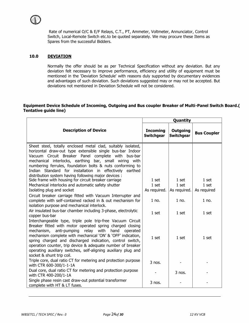
Equipment Device Schedule of Incoming, Outgoing and Bus coupler Breaker of Multi-Panel Switch Board.( Tentative guide line)
Description of Device
Quantity
Incoming
Switchgear
Outgoing
Switchgear
Bus Coupler
Sheet steel, totally enclosed metal clad, suitably isolated, horizontal draw-out type extensible single bus-bar Indoor
Vacuum Circuit Breaker Panel complete with bus-bar mechanical interlocks, earthing bar, small wiring with
numbering ferrules, foundation bolts & nuts conforming to Indian Standard for installation in effectively earthed
distribution system having following major devices :
Side frame with housing for circuit breaker carriage 1 set 1 set 1 set
Mechanical interlocks and automatic safety shutter 1 set 1 set 1 set
Isolating plug and socket As required. As required. As required
Circuit breaker carriage fitted with Vacuum Interrupter and
complete with self-contained racked in & out mechanism for isolation purpose and mechanical interlock.
1 no.
1 no.
1 no.
Air insulated bus-bar chamber including 3-phase, electrolytic copper bus-bar
1 set 1 set 1 set
Interchangeable type, triple pole trip-free Vacuum Circuit
Breaker fitted with motor operated spring charged closing
mechanism, anti-pumping relay with hand operated mechanism complete with mechanical „ON‟ & „OFF‟ indication,
spring charged and discharged indication, control switch, operation counter, trip device & adequate number of breaker
operating auxiliary switches, self-aligning auxiliary plug and
socket & shunt trip coil.
1 set
1 set
1 set
Triple core, dual ratio CT for metering and protection purpose with CTR 600-300/1-1-1A
3 nos. - -
Dual core, dual ratio CT for metering and protection purpose with CTR 400-200/1-1A
- 3 nos. -
Single phase resin cast draw-out potential transformer complete with HT & LT fuses.
3 nos. - -
WBSETCL / TECH SPEC / Rev.-3 Page 25of 30 12 KV VCB
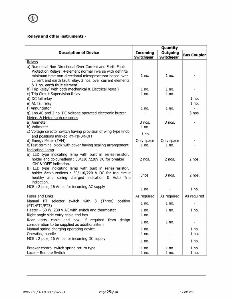
Relays and other instruments -
Description of Device
Quantity
Incoming Switchgear
Outgoing Switchgear
Bus Coupler
Relays a) Numerical Non-Directional Over Current and Earth Fault
Protection Relays: 4-element normal inverse with definite
minimum time non-directional microprocessor based over current and earth fault relay. 3 nos. over current elements
& 1 no. earth fault element.
1 no.
1 no.
-
b) Trip Relay( with both mechanical & Electrical reset ) 1 no. 1 no. -
c) Trip Circuit Supervision Relay 1 no. 1 no. -
d) DC fail relay 1 no.
e) AC fail relay 1 no.
f) Annunciator 1 no. 1 no. -
g) 1no.AC and 2 no. DC Voltage operated electronic buzzer - - 3 nos.
Meters & Metering Accessories a) Ammeter 3 nos. 3 nos. - b) Voltmeter 1 no. - -
c) Voltage selector switch having provision of wing type knob
and positions marked RY-YB-BR-OFF 1 no. - -
d) Energy Meter (TVM) Only space Only space - e)Test terminal block with cover having sealing arrangement 1 no. 1 no. -
Indicating Lamp a) LED type indicating lamp with built in series resistor,
holder and colouredlens : 30/110 /220V DC for breaker
„ON‟ & „OFF‟ indication.
2 nos.
2 nos.
2 nos.
b) LED type indicating lamp with built in series resistor,
holder &colouredlens : 30/110/220 V DC for trip circuit
healthy and spring charged indication & Auto Trip indication.
3nos.
3 nos.
2 nos.
MCB : 2 pole, 16 Amps for incoming AC supply 1 no. - 1 no.
Fuses and Links As required As required As required
Manual PT selector switch with 3 (Three) position
(PT1/PT2/PT3) 1 no. 1 no. -
Heater – 60 W, 230 V AC with switch and thermostat 1 no. 1 no. 1 no.
Right angle side entry cable end box 1 no. - -
Rear entry cable end box, if required from design
consideration to be supplied as additionalitem 1 no. 1 no. -
Manual spring charging operating device. 1 no. - 1 no.
Operating handle 1 no. - 1 no.
MCB : 2 pole, 16 Amps for incoming DC supply 1 no. - 1 no.
Breaker control switch spring return type 1 no. 1 no. 1 no.
Local – Remote Switch 1 no. 1 no. 1 no.
WBSETCL / TECH SPEC / Rev.-3 Page 26of 30 12 KV VCB
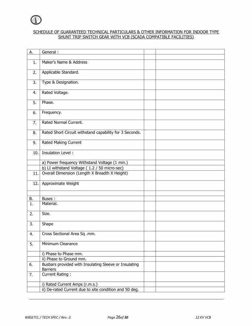
SCHEDULE OF GUARANTEED TECHNICAL PARTICULARS & OTHER INFORMATION FOR INDOOR TYPE
SHUNT TRIP SWITCH GEAR WITH VCB (SCADA COMPATIBLE FACILITIES)
A. General :
1. Maker‟s Name & Address
2. Applicable Standard.
3. Type & Designation.
4. Rated Voltage.
5. Phase.
6. Frequency.
7. Rated Normal Current.
8. Rated Short Circuit withstand capability for 3 Seconds.
9. Rated Making Current
10. Insulation Level :
a) Power frequency Withstand Voltage (1 min.) b) LI withstand Voltage ( 1.2 / 50 micro-sec)
11. Overall Dimension (Length X Breadth X Height)
12. Approximate Weight
B. Buses : 1. Material.
2. Size.
3. Shape
4. Cross Sectional Area Sq .mm.
5. Minimum Clearance
i) Phase to Phase mm. ii) Phase to Ground mm. 6. Busbars provided with Insulating Sleeve or Insulating
Barriers
7. Current Rating :
i) Rated Current Amps (r.m.s.) ii) De-rated Current due to site condition and 50 deg.
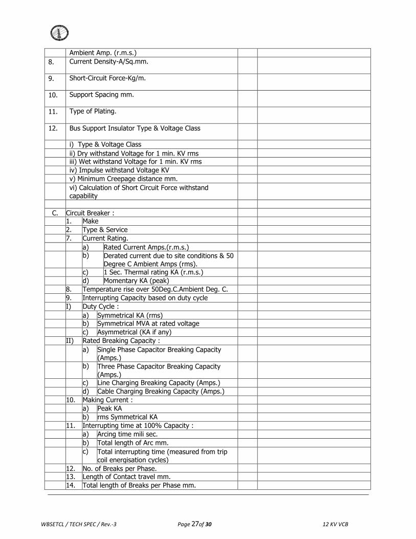
WBSETCL / TECH SPEC / Rev.-3 Page 27of 30 12 KV VCB
Ambient Amp. (r.m.s.) 8. Current Density-A/Sq.mm.
9. Short-Circuit Force-Kg/m.
10. Support Spacing mm.
11. Type of Plating.
12. Bus Support Insulator Type & Voltage Class
i) Type & Voltage Class ii) Dry withstand Voltage for 1 min. KV rms iii) Wet withstand Voltage for 1 min. KV rms iv) Impulse withstand Voltage KV v) Minimum Creepage distance mm. vi) Calculation of Short Circuit Force withstand
capability
C. Circuit Breaker :
1. Make 2. Type & Service 7. Current Rating. a) Rated Current Amps.(r.m.s.) b) Derated current due to site conditions & 50
Degree C Ambient Amps (rms).
c) 1 Sec. Thermal rating KA (r.m.s.) d) Momentary KA (peak) 8. Temperature rise over 50Deg.C.Ambient Deg. C. 9. Interrupting Capacity based on duty cycle I) Duty Cycle : a) Symmetrical KA (rms) b) Symmetrical MVA at rated voltage c) Asymmetrical (KA if any) II) Rated Breaking Capacity : a) Single Phase Capacitor Breaking Capacity
(Amps.)
b) Three Phase Capacitor Breaking Capacity
(Amps.)
c) Line Charging Breaking Capacity (Amps.) d) Cable Charging Breaking Capacity (Amps.) 10. Making Current : a) Peak KA b) rms Symmetrical KA 11. Interrupting time at 100% Capacity : a) Arcing time mili sec. b) Total length of Arc mm. c) Total interrupting time (measured from trip
coil energisation cycles)
12. No. of Breaks per Phase. 13. Length of Contact travel mm. 14. Total length of Breaks per Phase mm.

WBSETCL / TECH SPEC / Rev.-3 Page 28of 30 12 KV VCB
15. Rate of Contact travel cm/sec.
16. Endurance Capacity :
a) Mechanical. b) Electrical.(fault clearing operation) 17. Vacuum Bottle Particulars : a) Rated Voltage. b) Normal Current c) Short time Current. i) Symmetrical. ii) Asymmetrical. d) Making Current. e) Total Weight. f) Contact Force due to atmospheric pressure. g) Maximum Contact separation length. h) Maximum Contact erosion. i) Average Opening speed. j) Closing Speed at contact touch. k) Maximum allowable over travel. l) Maximum allowable contact bounce duration. m) Maximum allowable contact chattering
duration.
n) Mechanical life in no. of operation o) Minimum electrical life in no. of operation. i) At rated normal Current. ii) At rated Symmetrical Short Circuit
Current.
iii) At 25% rated Symmetrical Short Circuit Current.
iv) At 50% rated Symmetrical Short Circuit Current.
p) Name and Address of the bottle Manufacturer with mention of type.
18. Insulation Level of Breaker : a) One min. dry withstand KV (rms.) b) Impulse withstand KV (peak) 19. Type of Contacts : a) Main. b) Arcing. 20. Material of Contacts : a) Main. b) Arcing. c) Type of Plating. d) Thickness of Plating. e) Contact Pressure. 21. Minimum Clearance : a) Between live parts and ground. b) Between Poles. 22. Type of Operating Mechanism : a) Closing. b) Tripping.
12KVVCB WBSETCL Page 24 of26
WBSETCL / TECH SPEC / Rev.-3 Page 29 of 30 12 KV VCB
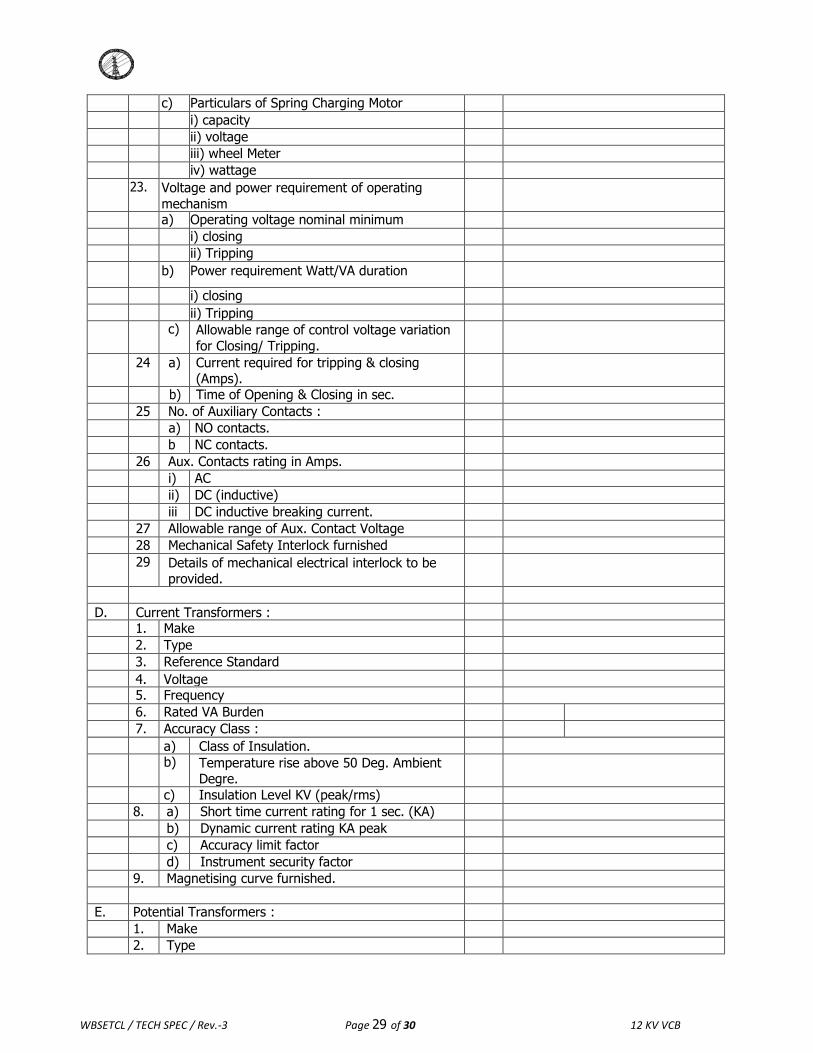
c) Particulars of Spring Charging Motor i) capacity ii) voltage iii) wheel Meter iv) wattage 23. Voltage and power requirement of operating
mechanism
a) Operating voltage nominal minimum i) closing ii) Tripping b) Power requirement Watt/VA duration
i) closing ii) Tripping c) Allowable range of control voltage variation
for Closing/ Tripping.
24 a) Current required for tripping & closing (Amps).
b) Time of Opening & Closing in sec. 25 No. of Auxiliary Contacts : a) NO contacts. b NC contacts. 26 Aux. Contacts rating in Amps. i) AC ii) DC (inductive) iii DC inductive breaking current. 27 Allowable range of Aux. Contact Voltage 28 Mechanical Safety Interlock furnished 29 Details of mechanical electrical interlock to be
provided.
D. Current Transformers :
1. Make 2. Type 3. Reference Standard 4. Voltage 5. Frequency 6. Rated VA Burden 7. Accuracy Class : a) Class of Insulation. b) Temperature rise above 50 Deg. Ambient
Degre.
c) Insulation Level KV (peak/rms) 8. a) Short time current rating for 1 sec. (KA) b) Dynamic current rating KA peak c) Accuracy limit factor d) Instrument security factor 9. Magnetising curve furnished. E. Potential Transformers :
1. Make 2. Type

WBSETCL / TECH SPEC / Rev.-3 Page 30of 30 12 KV VCB
3. Reference Standard 4. Frequency 5. a) Rated Primary Voltage b) Rated Secondary Voltage c) Winding Connection. 6. a) Rated VA Burden per Phase. b) VA Burden Thermal Limit. 7. Accuracy Class : 8. a) Class of Insulation. b) Temperature Rise above 10 Deg.C 9. Over Voltage Factor. 10. Overall Dimension. 11. Weight. 12. Fuses L: a) H.V. b) L.V.
Relay Particulars –
Sl.No. Type of Relay Make Type Range
1. IDMT over current & earth fault relay(as
per Sl. No.8.5 of the Specification).
2. Microprocessor based electronic
Annunciator.
3. Anti Pumping Relay. 4. Tripping Relay.
Related Documents