12 CO2 Laser and Micro-Fluidics Mohammadreza Riahi Shahid Beheshti University/Laser and Plasma Research Institute Iran 1. Introduction Microfluidic chips have attracted significant attention over the past decade due to their wide range of potential applications in the biomedical and chemical analysis field such as drug delivery, Point of care diagnostics (Jakeway et al, 2004), flow cytometry (Fu LM et al 2004; Chen & Wang, 2009; Lin et al, 2009), polymerize chain reaction (Suna et al, 2007; Sun & Kwok, 2006; Hsieh et al, 2009), electrophoresis (Fu et al, 2007, 2009) and many other applications. Traditionally, silicon and glass are the predominant materials employed in the design of microfluidic systems. This was primarily due to their excellent chemical, physical, electrical and optical properties. But fabrication of a microfluidic device on these materials needs standard photolithography equipments such as Reactive Ion Etching (RIE) system which are very expensive and increases the production costs specially in single-use applications which are desired in order to avoid contamination. In recent years application of polymeric materials for microfluidic device fabrication is becoming more and more important. Different methods for microfluidic fabrication on polymers such as hot embossing (Gerlach et al, 2002), injection molding (Rotting et al, 2002), soft lithography (Xia et al, 1998) and laser micromachining can be applied. Different kind of lasers such as UV (Ball et al, 2000) and Infrared lasers is used for laser micromachining of polymers. In infrared regime, CO2 laser has a predominant application due to it’s excellent absorption in polymers. In this chapter, we will deal with application of a CO2 laser in microfluidic device fabrication. The application of CO2 laser for fabrication of a optofluidic device and application of a optofluidic device for CO2 laser characterization is also presented. 2. Interaction of a CO2 laser with polymers Application of the CO2 laser for microfluidic device fabrication was first proposed in 2002 by H. Klank et al (Klank et al, 2002). CO2 laser emits radiation with the wavelength of 10.6 micrometer. A CO2 laser mostly interacts with a polymer, photo-thermally. When a CO2 laser is irradiated on a polymer surface, it is strongly absorbed and raises the temperature of the polymer. The polymer is then melted, decomposed and leaving a void in a workpiece. www.intechopen.com

Welcome message from author
This document is posted to help you gain knowledge. Please leave a comment to let me know what you think about it! Share it to your friends and learn new things together.
Transcript
12
CO2 Laser and Micro-Fluidics
Mohammadreza Riahi Shahid Beheshti University/Laser and Plasma Research Institute
Iran
1. Introduction
Microfluidic chips have attracted significant attention over the past decade due to their wide range of potential applications in the biomedical and chemical analysis field such as drug delivery, Point of care diagnostics (Jakeway et al, 2004), flow cytometry (Fu LM et al 2004; Chen & Wang, 2009; Lin et al, 2009), polymerize chain reaction (Suna et al, 2007; Sun & Kwok, 2006; Hsieh et al, 2009), electrophoresis (Fu et al, 2007, 2009) and many other applications.
Traditionally, silicon and glass are the predominant materials employed in the design of microfluidic systems. This was primarily due to their excellent chemical, physical, electrical and optical properties. But fabrication of a microfluidic device on these materials needs standard photolithography equipments such as Reactive Ion Etching (RIE) system which are very expensive and increases the production costs specially in single-use applications which are desired in order to avoid contamination.
In recent years application of polymeric materials for microfluidic device fabrication is becoming more and more important. Different methods for microfluidic fabrication on polymers such as hot embossing (Gerlach et al, 2002), injection molding (Rotting et al, 2002), soft lithography (Xia et al, 1998) and laser micromachining can be applied.
Different kind of lasers such as UV (Ball et al, 2000) and Infrared lasers is used for laser micromachining of polymers. In infrared regime, CO2 laser has a predominant application due to it’s excellent absorption in polymers.
In this chapter, we will deal with application of a CO2 laser in microfluidic device fabrication. The application of CO2 laser for fabrication of a optofluidic device and application of a optofluidic device for CO2 laser characterization is also presented.
2. Interaction of a CO2 laser with polymers
Application of the CO2 laser for microfluidic device fabrication was first proposed in 2002 by H. Klank et al (Klank et al, 2002).
CO2 laser emits radiation with the wavelength of 10.6 micrometer. A CO2 laser mostly interacts with a polymer, photo-thermally. When a CO2 laser is irradiated on a polymer surface, it is strongly absorbed and raises the temperature of the polymer. The polymer is then melted, decomposed and leaving a void in a workpiece.
www.intechopen.com
CO2 Laser – Optimisation and Application
308
Different kind of polymers can be used for microfluidic applications by taking a choice care that the fluid in the device do not interact chemically with the device. However just some of the polymers can be machined with CO2 laser. Most of the polymers leave contamination and soot when exposed to CO2 laser irradiation. For example, polycarbonate (PC) leaves a brownish residue after exposing to the CO2 laser.
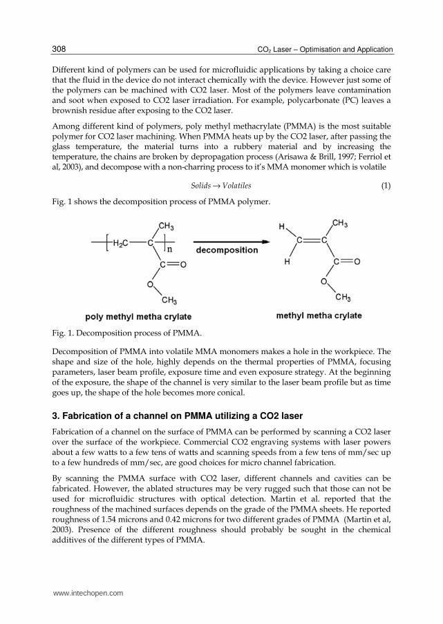
Among different kind of polymers, poly methyl methacrylate (PMMA) is the most suitable polymer for CO2 laser machining. When PMMA heats up by the CO2 laser, after passing the glass temperature, the material turns into a rubbery material and by increasing the temperature, the chains are broken by depropagation process (Arisawa & Brill, 1997; Ferriol et al, 2003), and decompose with a non-charring process to it’s MMA monomer which is volatile
Solids Volatiles→ (1)
Fig. 1 shows the decomposition process of PMMA polymer.
Fig. 1. Decomposition process of PMMA.
Decomposition of PMMA into volatile MMA monomers makes a hole in the workpiece. The shape and size of the hole, highly depends on the thermal properties of PMMA, focusing parameters, laser beam profile, exposure time and even exposure strategy. At the beginning of the exposure, the shape of the channel is very similar to the laser beam profile but as time goes up, the shape of the hole becomes more conical.
3. Fabrication of a channel on PMMA utilizing a CO2 laser
Fabrication of a channel on the surface of PMMA can be performed by scanning a CO2 laser over the surface of the workpiece. Commercial CO2 engraving systems with laser powers about a few watts to a few tens of watts and scanning speeds from a few tens of mm/sec up to a few hundreds of mm/sec, are good choices for micro channel fabrication.
By scanning the PMMA surface with CO2 laser, different channels and cavities can be fabricated. However, the ablated structures may be very rugged such that those can not be used for microfluidic structures with optical detection. Martin et al. reported that the roughness of the machined surfaces depends on the grade of the PMMA sheets. He reported roughness of 1.54 microns and 0.42 microns for two different grades of PMMA (Martin et al, 2003). Presence of the different roughness should probably be sought in the chemical additives of the different types of PMMA.
www.intechopen.com
CO2 Laser and Micro-Fluidics
309
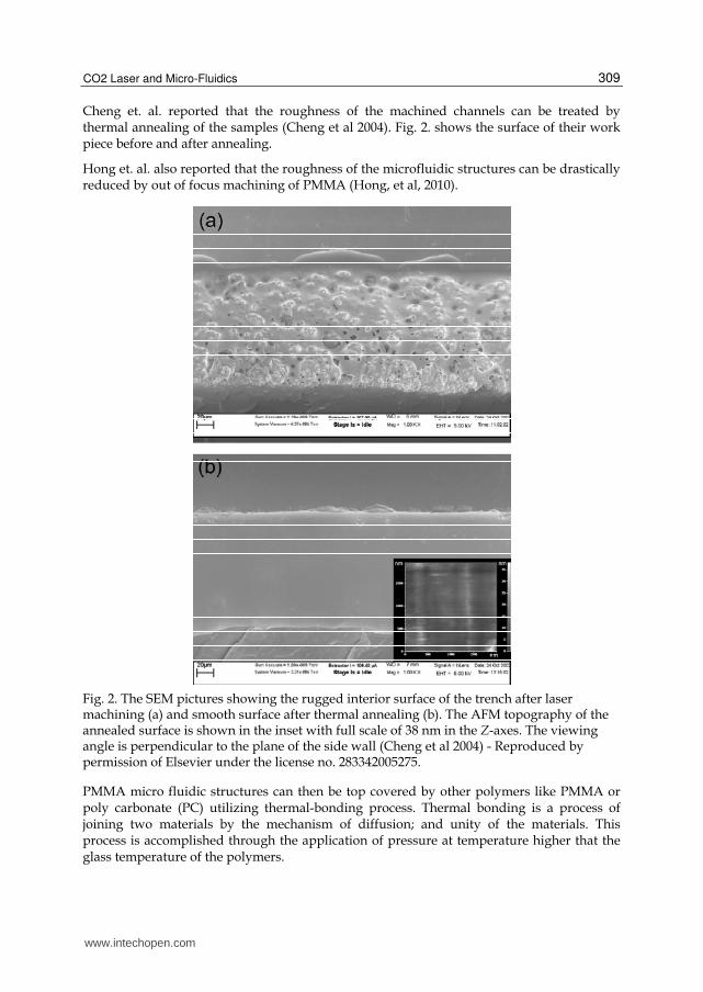
Cheng et. al. reported that the roughness of the machined channels can be treated by thermal annealing of the samples (Cheng et al 2004). Fig. 2. shows the surface of their work piece before and after annealing.
Hong et. al. also reported that the roughness of the microfluidic structures can be drastically reduced by out of focus machining of PMMA (Hong, et al, 2010).
Fig. 2. The SEM pictures showing the rugged interior surface of the trench after laser machining (a) and smooth surface after thermal annealing (b). The AFM topography of the annealed surface is shown in the inset with full scale of 38 nm in the Z-axes. The viewing angle is perpendicular to the plane of the side wall (Cheng et al 2004) - Reproduced by permission of Elsevier under the license no. 283342005275.
PMMA micro fluidic structures can then be top covered by other polymers like PMMA or poly carbonate (PC) utilizing thermal-bonding process. Thermal bonding is a process of joining two materials by the mechanism of diffusion; and unity of the materials. This process is accomplished through the application of pressure at temperature higher that the glass temperature of the polymers.
www.intechopen.com

CO2 Laser – Optimisation and Application
310
In addition to fabrication of the holes, channels and cavities, CO2 laser machining can be used to make some complicated structures, like bending holes. These structures can also be molded with other materials such as PDMS to get the negative of the PMMA structures. In the next section fabrication technique of the other complicated structure with 3D structure is presented.
4. Fabrication of a 3D Mixer with CO2 laser machining of PMMA and PDMS molding
In this section we present application of a CO2 laser for fabrication of a 3D mixer with bending cones (Riahi, 2012). Mixers are the elements in microfluidic and micro total analysis systems which are used for mixing two or more liquids in biological and chemical analyses. Mixers can be divided into the two categories, active and passive. In active mixers, an external actuation mechanism is used to mix liquids in a microfluidic chamber. In passive mixers, there is no energy consumption and the structure of these devices is simpler than that of active devices. Different schemes such as a Tesla structure (Hong et al, 2004), a T mixer (Hoe et al, 2004), a 3D serpentine (Liu et al, 2000) and twisted shapes (Bertsch et al, 2001) are also used in passive micro mixers.
The technique which is presented here is based on the application of the CO2 laser for
fabrication of some bending and straight cones on PMMA followed by PDMS molding. The
designed mixer is shown in Fig. 3.
Fig. 3. Schematic of the designed 3D mixer (Riahi, 2012).
www.intechopen.com

CO2 Laser and Micro-Fluidics
311
4.1 Fabrication of the bending cones
When a shape, is engraved in a raster scan mode by a CO2 laser engraving system on
PMMA, the system scans a shape, row by row which each row has a certain overlap with a
previous row. During the first row scan, a symmetrical V-shape channel is ablated on the
PMMA surface. When the laser scans the subsequent rows, a small portion of the laser beam
reflects from the wall of the channel produced by the previous scan to the bottom of the hole
in the opposite side of the scanning direction as shown in Fig. 4a. After several scans, the
reflected beam can ablate a considerable amount of PMMA material at the bottom of the
hole at the opposite side of the scanning direction which can causes a bending shape in the
structure (Fig. 4b).
Fig. 4. Ablation of a PMMA hole with CO2 laser. a) Reflection of the laser from the walls of an ablated hole. b) The shape of the hole after several scans (Riahi, 2012).
It is found that the shape of the holes can be controlled by adjusting the scanning parameters such as resolution, power and scan speed. Some of the fabricated holes have very bent shapes and some are straight. Fig. 5 shows the ablated bending holes for different scan parameters.
Fig. 5. The ablated bending holes for different scan parameters (Riahi, 2012).
www.intechopen.com

CO2 Laser – Optimisation and Application
312
4.2 Ablation of the mixer structure
To fabricate the mixer, a few straight cones and bending cones are ablated with CO2 laser on two different PMMA sheets. One of the PMMA sheets is CO2 laser cut to form a channel with two inputs and one output. The structures are then molded with PDMS and one is placed upside down on top of the other. Fig. 6. shows the fabricated channels and holes on the PMMA sheet and the molded PDMS structure.
Fig. 6. a) Fabricated structures on PMMA sheets. b) The PDMS molds of structures shown in part a. The straight and bending cones are clear (Riahi, 2012).
Fig. 7. The fabricated mixer (Riahi, 2012).
www.intechopen.com

CO2 Laser and Micro-Fluidics
313
The molded PDMS structures are then stacked to each other and three steel tubes are inserted into the input and output channels and the voids are filled with PDMS to form the final mixer structure. The fabricated mixer is shown in Fig. 7.
5. Fabrication of the structures for optofluidics applications
Optofluidics refers to a science that uses the optical property of fluids for adjusting, measuring the properties of a device. Some examples of such devices are, liquid mirrors (Wood, 1909), liquid-crystal displays (Haas, 1983) and liquid lenses (Kuiper & Hendriks, 2004).
Several techniques are used to fabricate a tunable lens array (Dong et al, 2006; Jeong et al, 2004; Xu et al 2009)
In this section we show how a CO2 laser can be used for fabrication of an optofluidic device, liquid micro lens array (Riahi, 2011).
The liquid microlens array is an array of tunable liquid lenses which can be used for Medical
stereoendoscopy, Telecommunication, Optical data storage, Photonic imaging, etc.
Fig. 8. shows the basic structure of the liquid lens array which is presented here. An array of
the hexagonal holes with about 2mm width each, are first fabricated on a 1mm thick PMMA
sheet. A thin layer of PDMS with the thickness of about 50 microns is fabricated and placed
on the array of holes. A 1mm depth reservoir with an inlet and outlet for the fluid is also
fabricated. The whole of the collection are placed on top of each other.
Fig. 8. The structure of a tunable liquid lens array.
By introducing a liquid into the reservoir and changing the pressure inside, the curvature
of the PDMS sheet in place of the holes changes and produces convex lenses as shown in
Fig. 9.
www.intechopen.com
CO2 Laser – Optimisation and Application
314
Fig. 9. Mechanism of convex micro lens creation by applying pressure in a water reservoir limited by PDMS and PMMA walls.
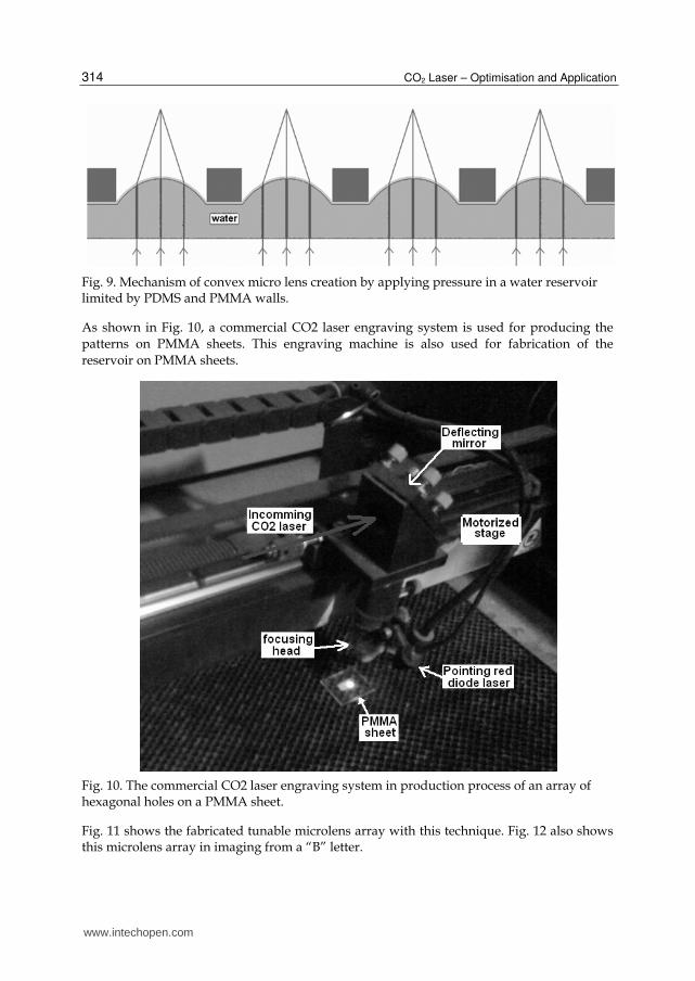
As shown in Fig. 10, a commercial CO2 laser engraving system is used for producing the
patterns on PMMA sheets. This engraving machine is also used for fabrication of the
reservoir on PMMA sheets.
Fig. 10. The commercial CO2 laser engraving system in production process of an array of hexagonal holes on a PMMA sheet.
Fig. 11 shows the fabricated tunable microlens array with this technique. Fig. 12 also shows this microlens array in imaging from a “B” letter.
www.intechopen.com

CO2 Laser and Micro-Fluidics
315
Fig. 11. The fabricated tunable liquid lens array.
Fig. 12. Imaging from the letter “B” with the fabricated liquid lens array.
www.intechopen.com
CO2 Laser – Optimisation and Application
316
6. Fabrication of a beam profiler using the optical properties of liquids
In the previous sections we focused on the application of the CO2 laser for fabrication of the
devices used in microfluidics and optofluidics. In this section we look at the application of a
fluid device which is used for CO2 laser characterization. We present a device called
thermally tunable grating (TTG), which can be used as a CO2 laser beam profiler.
Thermally tunable grating is a family of the gratings which some of their specifications can
be adjusted by the user. The tuning ability of a diffractive grating can be divided into two
categories: first, gratings in which the diffractive angle can be tuned, and second, gratings in
which the intensity of diffraction orders can be modulated which are called grating light
valves (GLV). Electrostatic actuation is one of the methods used in MEMS based grating
light valves system (Trisnadi et al, 2004). In this grating light valve system, tiny suspended
ribbons are put together to form a specular surface. Electrostatic actuation lowers some of
the ribbons, and a diffractive grating is formed. Electric field actuation has also been used to
actuate an electro-optically controlled liquid crystal based GLV (Chen et al, 1995).
But in TTG device, thermal method is used for actuation of a grating which contains a liquid
in it’s grooves. Increasing temperature, changes the refractive index of the liquid and
consequently the diffraction efficiency of the grating (Riahi et al, 2008).
6.1 Principle of the method
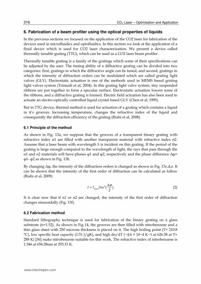
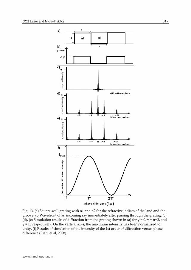
As shown in Fig. 13a, we suppose that the grooves of a transparent binary grating with
refractive index n1 are filled with another transparent material with refractive index n2.
Assume that a laser beam with wavelength λ is incident on this grating. If the period of the
grating is large enough compared to the wavelength of light, the rays that pass through the
n1 and n2 materials will have phases φ1 and φ2, respectively and the phase difference Δφ=
φ1- φ2 as shown in Fig. 13b.
By changing Δφ, the intensity of the diffraction orders is changed as shown in Fig. 13c,d,e. It
can be shown that the intensity of the first order of diffraction can be calculated as follow
(Riahi et al, 2009):
2max ( )
2I I Sin
ϕ∆= (2)
It is clear now that if n1 or n2 are changed, the intensity of the first order of diffraction
changes sinusoidally (Fig. 13f).
6.2 Fabrication method
Standard lithography technique is used for fabrication of the binary grating on a glass
substrate (n=1.52). As shown in Fig 14, the grooves are then filled with nitrobenzene and a
thin glass sheet with 250 microns thickness is placed on it. The high boiling point (T= 210:8
°C), low specific heat capacity (1:51 J/gK), and high dn/dT (−4:6 × 10⁻⁴ K−1 at 626.58 at T=
288 K) [36] make nitrobenzene suitable for this work. The refractive index of nitrobenzene is
1.546 at 656:28nm at 293:15 K.
www.intechopen.com
CO2 Laser and Micro-Fluidics
317
Fig. 13. (a) Square-well grating with n1 and n2 for the refractive indices of the land and the groove. (b)Wavefront of an incoming ray immediately after passing through the grating. (c), (d), (e) Simulation results of diffraction from the grating shown in (a) for γ = 0, γ = π=2, and γ = π, respectively. On the vertical axes, the maximum intensity has been normalized to unity. (f) Results of simulation of the intensity of the 1st order of diffraction versus phase difference (Riahi et al, 2008).
norm
aliz
ed in
tens
ity
norm
aliz
ed in
tens
ity
norm
aliz
ed in
tens
ity
www.intechopen.com

CO2 Laser – Optimisation and Application
318
The diffraction pattern and intensity of the first order of diffraction versus temperature has
been presented in Fig. 15.
6.3 Measurement of the beam profile of a CO2 laser
By changing the temperature, the intensity of the 1st order of diffraction is changed. The
temperature of the TTG changes upon radiation by a CO2 laser beam. Radiation of a CO2
laser beam on a substrate warms it up and produces a temperature profile on the surface of
the substrate. The temperature profile depends on the intensity profile of the laser beam. For
example, if the laser profile is circular Gaussian, the temperature profile on the surface will
be circular Gaussian in ideal case. Now if another visible laser is expanded and diffracted
from the surface of the grating, the laser will be diffracted in different amounts from
different parts of the grating, containing information on the temperature profile on the
grating.
The setup shown in Fig. 16 is used to measure the beam profile of a CO2 laser. In this setup,
a CO2 laser and a 658nm diode laser are made collinear with each other using a ZnSe
window, and finally both lasers are irradiated on a 4mm × 4mm TTG device. The diode
laser is expanded to about 3 cm diameter to cover the 4mm × 4mm TTG device with
uniform intensity. The CO2 laser is passed through a shutter so that the irradiation time
can be controlled. Immediately after the CO2 laser pulse, the CCD camera takes a picture
from diffracted diode laser by a 4f imaging system using the 1st order of diffraction. It
takes about 1 min for the device to get cool enough to repeat the experiment. The heat
gun shown in Fig. 16. is used to keep the working area between point A and B as specified
in Fig. 15d.
Fig. 14. Fabrication of the TTG device: (a) the grooves of the grating are filled with nitrobenzene and (b) a supporting glass is placed on the device (Riahi et al, 2008).
www.intechopen.com

CO2 Laser and Micro-Fluidics
319
Fig. 15. Diffraction order intensities at different temperatures: (a) T = 77 °C, (b) T = 108 °C, and (c) T = 140 °C. The maximum intensity is normalized to unity. (d) Experimental result of the intensity of the 1st order of diffraction versus temperature. The maximum intensity is normalized to unity (Riahi et al, 2008).
Fig. 16. Setup used for measurement of the temperature profile of the CO2 laser (Riahi et al, 2008).
The Image produced on the CCD camera and measured beam profile of the CO2 laser is shown in Fig. 17.
www.intechopen.com

CO2 Laser – Optimisation and Application
320
Fig. 17. (a) Image produced on the CCD camera. (b) 3D intensity profile of “a” will be the same as the beam profile of the CO2 laser (Riahi et al, 2008).
The followings are some errors presented in this experiment.
- additional temperature Gradient on the Thermally Tunable Grating because of the environmental errors
- Thickness of the Supporting Glass - Aberrations of the Grating - Expansion of the Grating - Beam Profile of the Diode Laser
Some of these errors are so small to affect the beam profile, but some of them might be important and have to be corrected.
7. Real time measurement of the CO2 laser beam profile utilizing TTG
In method we presented in the previous section, after each measurement, time had to be taken for the grating to cool down and get ready for another measurement. This can be a big
www.intechopen.com
CO2 Laser and Micro-Fluidics
321
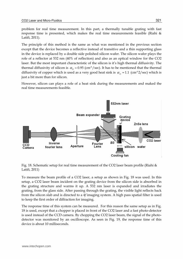
problem for real time measurement. In this part, a thermally tunable grating with fast response time is presented, which makes the real time measurements feasible (Riahi & Latifi, 2011).
The principle of this method is the same as what was mentioned in the previous section
except that the device becomes a reflective instead of transitive and a thin supporting glass
in the device is replaced by a double side polished silicon wafer. The silicon wafer plays the
role of a reflector at 532 nm (40% of reflection) and also as an optical window for the CO2
laser. But the most important characteristic of the silicon is it’s high thermal diffusivity. The
thermal diffusivity of silicon is 0.95Siα = (cm^/sec). It has to be mentioned that the thermal
diffusivity of copper which is used as a very good heat sink is 1.1cuα = (cm^2/sec) which is
just a bit more than for silicon.
However, silicon can plays a role of a heat sink during the measurements and maked the real time measurements feasible.
Fig. 18. Schematic setup for real time measurement of the CO2 laser beam profile (Riahi & Latifi, 2011)
To measure the beam profile of a CO2 laser, a setup as shown in Fig. 18 was used. In this
setup, a CO2 laser beam incident on the grating device from the silicon side is absorbed in
the grating structure and warms it up. A 532 nm laser is expanded and irradiates the
grating, from the glass side. After passing through the grating, the visible light reflects back
from the silicon slab and is directed to a 4f imaging system. A high pass spatial filter is used
to keep the first order of diffraction for imaging.
The response time of this system can be measured. For this reason the same setup as in Fig.
18 is used, except that a chopper is placed in front of the CO2 laser and a fast photo-detector
is used instead of the CCD camera. By chopping the CO2 laser beam, the signal of the photo-
detector was monitored by an oscilloscope. As seen in Fig. 19, the response time of this
device is about 10 milliseconds.
www.intechopen.com

CO2 Laser – Optimisation and Application
322
Fig. 19. Detected signals from photo-diode when CO2 laser is chopped off and on
8. Conclusion
In this chapter, the relation between CO2 laser and fluid applications was presented. First, application of a CO2 laser for fabrication of microfluidic and optofluidic structures on PMMA polymer was presented. Then application of a fluidic device for measurement of a characteristic of a CO2 laser was discussed.
Application of the CO2 laser for microfluidic fabrication is a simple and low cost method which can be performed by a commercial CO2 laser engraving system. This method makes the final products very cheap which are suitable for single use applications.
Also it seems that the application of the CO2 laser in microfluidics shows a good potential for fabrication of some complicated structures even 3D structures for future works.
9. References
Arisawa H and Brill T B (1997) Kinetics and mechanisms of flash pyrolysis of poly (methyl methacrylate) (PMMA) Combust. Flame Vol. 109, pp. 415–26, ISSN 0010-2180
Ball J. C., Scott D. L., Lumpp J. K., Daunert S., Wang J. and Bachas L. G., (2000), Electrochemistry in Nanovials Fabricated by Screen Printing and Laser Micromachining Anal. Chem , Vol. 72, pp. 497–501, ISSN 0003-2700.
Bertsch A. , Heimgartner S., Cousseau P., Renaud P. ( 2001) 3D micromixers— downscaling large scale industrial static mixers, Proc. IEEE MEMS Workshop, Interlaken, Switzerland.
Chen HT, Wang YN (2009) Optical microflow cytometer for particle counting, sizing and fluorescence detection. Microfluid Nanofluid Vol. 6, pp. 529–537, ISSN (printed) 1613-4982. ISSN (electronic) 1613-4990
Chen J., Bos P. J., Vithana H., and Johnson D. L. (1995), An electrooptically controlled liquid crystal diffraction grating, Appl. Phys. Lett. Vol. 67, pp. 2588–2590, ISSN (print) 0003-6951 ISSN (online) 1077-3118.
Cheng Ji-yen, Cheng-Wey Wei, Kai-Hsiung Hsua (2004), Direct-write laser micromachining and universal surface modification of PMMA for device development, Sensors and Actuators B , Vol. 99, pp. 186–196, ISSN 0925-4005.
Dong L., Abhishek K. Agarwal1, David J. Beebe2 & Hongrui Jiang, (2006), Adaptive liquid microlenses activated by stimuliresponsive hydrogels, Nature, Vol 442, pp. 551-554, ISSN 0028-0836.
www.intechopen.com

CO2 Laser and Micro-Fluidics
323
Ferriol M, Gentilhomme A, Cochez M, Oget N and Mieloszynski J L (2003), Thermal degradation of poly (methyl methacrylate) (PMMA): modelling of DTG and TG curves Polym. Degrad. Stab. Vol. 79, pp. 271–81, ISSN 0141-3910.
Fu LM, Yang RJ, Lin CH, Lee GB, Pan YJ. (2004), Electrokinetically driven micro flow cytometers with integrated fiber optics for online cell/particle detection. Anal Chim Acta, Vol. 507, pp. 163–169, ISSN 0003-2670.
Fu LM, Leong JC, Lin CF, Tai CH, Tsai CH (2007), High performance microfluidic capillary electrophoresis devices, Biomed Microdevices, Vol. 9, pp. 405–412, ISSN 1387-2176 (Print) ; 1572-8781 (Electronic) ; 1387-2176 (Linking).
Fu LM, Wang JH, Luo WB, Lin CH (2009), Experimental and numerical investigation into the joule heating effect for electrokinetically driven microfluidic chips utilizing total internal reflection fluorescence microscopy, Microfluid Nanofluid, Vol. 6, pp. 499–507, ISSN (printed) 1613-4982. ISSN (electronic) 1613-4990.
Gerlach A, Knebel G., Guber A. E., Heckele M., Herrmann D., Muslija A. and Schaller Th. (2002), Microfabrication of single-use plastic microfluidic devices for high-throughput screening and DNA analysis, Microsyst. Technol. Vol. 7, pp.265–268, ISSN: 0946-7076 (print version) ISSN: 1432-1858 (electronic version)
Haas, W. E. (1983), Liquid-crystal display research — the first 15 years. Mol. Cryst. Liq. Cryst. Vol. 94, pp. 1–31, Print ISSN: 1542-1406 Online ISSN: 1563-5287.
Hoe Wong Seck, Michael C.L. Ward, Christopher W. Wharton (2004), Micro T-mixer as a rapid mixing micromixer, Sens. Actuators B, Vol. 100, pp. 359–379, ISSN 0925-4005.
Hong Chien-Chong, Jin-Woo Choi, Chong H. Ahn (2004), A novel in-plane passive microfluidic mixer with modified Tesla structures, Lab Chip, Vol. 4, pp. 109–113, ISSN (printed) 1473-0197. ISSN (electronic) 1473-0189.
Hong Ting-Fu, Ju Wei-Jhong, Wu Ming-Chang, Tai Chang-Hsien, Tsai Chien-Hsiung, Fu Lung-Ming (2010), Rapid prototyping of PMMA microfluidic chips utilizing a CO2 laser, Microfluid Nanofluid Vol.: 9, pp. 1125-1133, ISSN (printed) 1613-4982. ISSN (electronic) 1613-4990.
Hsieh TM, Luo CH, Wang JH, Lin JL, Lien KY, Lee GB (2009), A two-dimensional, self-compensated, microthermal cycler for one-step reverse transcription polymerase chain reaction applications, Microfluid Nanofluid, Vol. 2, pp.357–360, ISSN (printed) 1613-4982. ISSN (electronic) 1613-4990.
Jakeway s. C., A. J. de Mello and E. L. Russel, Fresenius’ J. (2000), Miniaturized total analysis systems for biological analysis. Anal. Chem. Vol. 366, pp. 525–539, ISSN 0003-2700.
Jeong Ki-Hun, Gang L. Liu, Nikolas Chronis and Luke P. Lee (2005), Tunable microdoublet lens array, Opt. Express., Vol. 12, pp. 2494-2500, ISSN 1094-4087.
Klank H., Jörg P. Kutter and Oliver Geschke (2002), CO2-laser micromachining and back-end processing for rapid production of PMMA-based microfluidic systems, Lab Chip, Vol. 2, pp. 242–246, ISSN (printed) 1473-0197. ISSN (electronic) 1473-0189.
Kuiper, S. & Hendriks, B. H. W. (2004), Variable-focus liquid lens for miniature cameras. Appl. Phys. Lett. Vol. 85, pp. 1128–1130, ISSN (print) 0003-6951 ISSN (online) 1077-3118.
Lin CH, Lee CY, Tsai CH, Fu LM (2009), Novel continuous particle sorting in microfluidic chip utilizing cascaded squeeze effect, Microfluid Nanofluid, Vol. 7, pp. 499–508, ISSN (printed) 1613-4982. ISSN (electronic) 1613-4990.
www.intechopen.com
CO2 Laser – Optimisation and Application
324
Liu Robin H., Mark Stremler A., Kendra V. Sharp, Michael G. Olsen, Juan G. Santiago, Ronald J. Adrian, Hassan Aref, David J. Beebe (2000), Passive mixing in a threedimensional serpentine microchannel, J. Microelectromech. Syst. Vol. 9, pp.190–197, ISSN: 1057-7157.
Martin F. Jensen,ab Mikkel Noerholm,bc Leif Højslet Christensena and Oliver Geschkeb (2003), Microstructure fabrication with a CO2 laser system: characterization and fabrication of cavities produced by raster scanning of the laser beam, Lab Chip, Vol. 3, pp. 302–307, ISSN (printed) 1473-0197. ISSN (electronic) 1473-0189.
Riahi M. (2012), Fabrication of a passive 3D mixer using CO2 laser ablation of PMMA and PDMS moldings Microchemical Journal, Vol. 100, pp. 14–20, ISSN 0026-265X.
Riahi M. (2011), Fabrication and characterization of a tunable liquid lens array in water-PDMS sheet interface by applying pressure , 1st EOS conference on optofluidics. (EOSOF2011) 23-25 may, Munich, Germany
Riahi M., Latifi H., and Moghimislam G. (2008), Fabrication of a thermally actuated tunable grating and its application as a CO2 laser beam profile analyzer, Appl. Opt. Vol. 47, pp. 5175-5181, ISSN: 1559-128X (print), ISSN: 2155-3165 (online)
Riahi M., Latifi H., Madani A., Moazzenzadeh A. (2009), Design and fabrication of a spatial light modulator using thermally tunable grating and thin film heater, Appl. Opt. Vol. 48, pp. 5647-5654, ISSN: 1559-128X (print), ISSN: 2155-3165 (online)
Riahi M., Latifi M. (2011), Fabrication of a 2D thermally tunable reflective grating for measuring a CO2 laser beam profile, Optica Applicata , Vol. 41. pp. 735-742, ISSN: 0078-5466.
Rotting O, Ropke W, Becker H and Gartner C. (2002), Polymer microfabrication technologies, Microsyst. Technol. Vol. 8, pp. 32–36, ISSN: 0946-7076 (print version) ISSN: 1432-1858 (electronic version)
Sun Y.,Y.C.Kwok (2006), Polymeric microfluidic system for DNA analysis, Anal. Chim. Acta Vol. 556, pp. 80–96, ISSN 0003-2670.
Suna Yi, Satyanarayan M.V.D., Nguyenb Nam Trung, Kwok Yien Chian (2008), Continuous flow polymerase chain reaction using a hybrid PMMA-PC microchip with improved heat tolerance, Sensors and Actuators B, Vol. 130, pp. 836–841, ISSN 0925-4005.
Trisnadi J. I., Carlisle C. B., and Monteverde R. (2004), Overview and applications of Grating Light Valve based optical write engines for high-speed digital imaging, presented at Photonics West2004—Micromachining and Microfabrication Symposium, 26 January, San Jose, California, USA.
Wood, R. W. (1909), The mercury paraboloid as a reflecting telescope. Astrophys. J., Vol. 29, pp. 164–176.
Xia Y. and Whitesides G. M. (1998), soft lithography, Annu. Rev. Mater. Sci., Vol. 28, pp. 153–184, ISSN: 0084-6600
Xu S., Lin Yeong-Jyh, and Wu Shin-Tson (2009), Dielectric liquid microlens with well-shaped electrode, Opt. Express, Vol. 17, pp. 10499-10505, ISSN 1094-4087.
www.intechopen.com

CO2 Laser - Optimisation and ApplicationEdited by Dr. Dan C. Dumitras
ISBN 978-953-51-0351-6Hard cover, 436 pagesPublisher InTechPublished online 21, March, 2012Published in print edition March, 2012
InTech EuropeUniversity Campus STeP Ri Slavka Krautzeka 83/A 51000 Rijeka, Croatia Phone: +385 (51) 770 447 Fax: +385 (51) 686 166www.intechopen.com
InTech ChinaUnit 405, Office Block, Hotel Equatorial Shanghai No.65, Yan An Road (West), Shanghai, 200040, China
Phone: +86-21-62489820 Fax: +86-21-62489821
The present book includes several contributions aiming a deeper understanding of the basic processes in theoperation of CO2 lasers (lasing on non-traditional bands, frequency stabilization, photoacoustic spectroscopy)and achievement of new systems (CO2 lasers generating ultrashort pulses or high average power, lasersbased on diffusion cooled V-fold geometry, transmission of IR radiation through hollow core microstructuredfibers). The second part of the book is dedicated to applications in material processing (heat treatment,welding, synthesis of new materials, micro fluidics) and in medicine (clinical applications, dentistry, non-ablativetherapy, acceleration of protons for cancer treatment).
How to referenceIn order to correctly reference this scholarly work, feel free to copy and paste the following:
Mohammadreza Riahi (2012). CO2 Laser and Micro-Fluidics, CO2 Laser - Optimisation and Application, Dr.Dan C. Dumitras (Ed.), ISBN: 978-953-51-0351-6, InTech, Available from:http://www.intechopen.com/books/co2-laser-optimisation-and-application/co2-laser-and-micro-fluidics
Related Documents