Office of Traffic and Safety Traffic Control Device Training Traffic Signal Design

Welcome message from author
This document is posted to help you gain knowledge. Please leave a comment to let me know what you think about it! Share it to your friends and learn new things together.
Transcript

Office of Traffic and Safety Traffic Control Device Training
Traffic Signal Design
Office of Traffic and Safety Traffic Control Device Training Traffic Signal Design
2
Agenda
AM Session
Introduction to Signal Design
Discussion of Design Request
Standards and Guidelines for Signal Design
Office and Field Survey Data Collection
PM Session
Conceptual Location of Signal Design Elements
Plan Development
Office of Traffic and Safety Traffic Control Device Training Traffic Signal Design
3
Purpose/Scope of Course
Create Stronger Base of Knowledge and
Information for Staff Working in Signal Design
Introduce Signal Design to Staff Working in
Other Disciplines
Provide Overview of SHA‟s Signal Design
Policies and Procedures
Create and Reinforce Awareness of Special
Design Considerations

Office of Traffic and Safety Traffic Control Device Training Traffic Signal Design
4
Responsibilities of the Signal Design Engineer
Ensure that the Final Design:
Conforms with the Design Request, FHWA &
SHA Standards, and ADA & NESC Regulations
Is completed in an approved format, with all of
the elements necessary for the Contractor to
perform the work as specified in the Design
Request
Is consistent/compatible with other Construction
Plans, where applicable
Can be built within the available budget

Office of Traffic and Safety Traffic Control Device Training Traffic Signal Design
5
Responsibilities of the Signal Design Engineer
Ensure that the Final Design:
Can be built within available right-of-way
Is not in conflict with existing or proposed utilities
Does not create environmental or property impacts
that cannot be readily mitigated
Is submitted for signatures at least one week in
advance of the PS&E date
Office of Traffic and Safety Traffic Control Device Training Traffic Signal Design
6
Definition of Traffic Control Signal
“A traffic control signal (traffic signal) shall
be defined as any highway traffic signal by
which traffic is alternately directed to stop
and permitted to proceed.” (MUTCD;
Section 4B.01)
Office of Traffic and Safety Traffic Control Device Training Traffic Signal Design
7
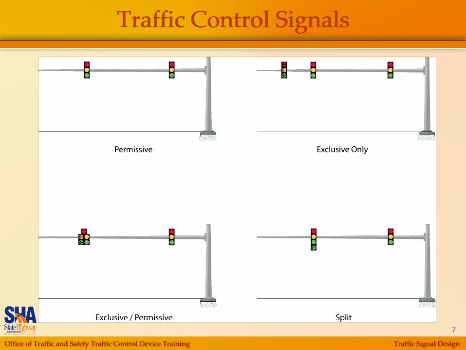
Traffic Control Signals
Office of Traffic and Safety Traffic Control Device Training Traffic Signal Design
8
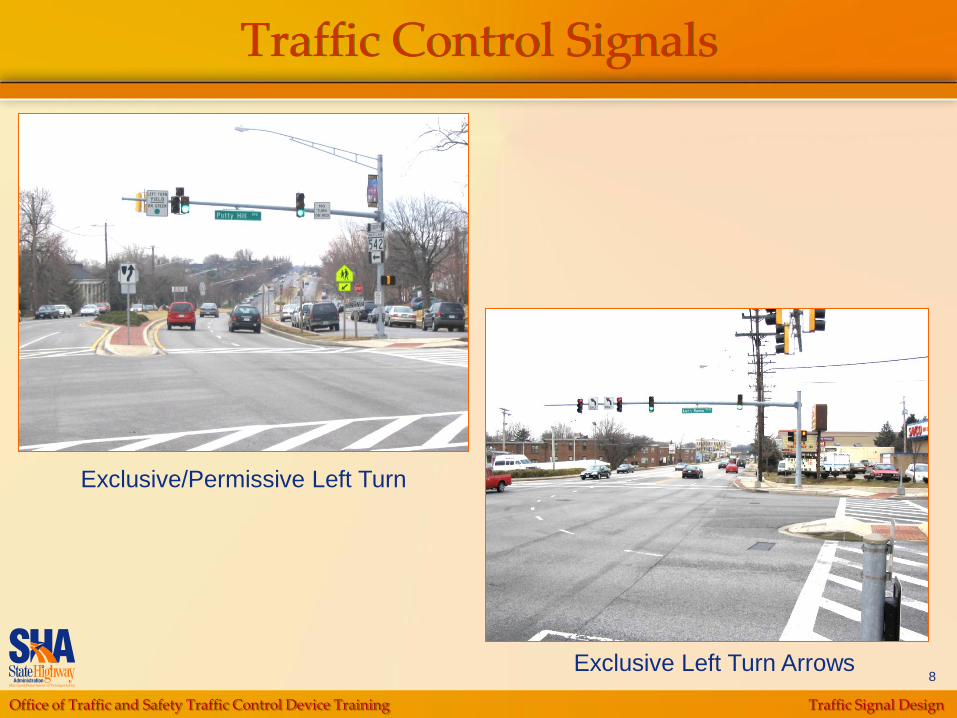
Traffic Control Signals
Exclusive/Permissive Left Turn
Exclusive Left Turn Arrows
Office of Traffic and Safety Traffic Control Device Training Traffic Signal Design
9
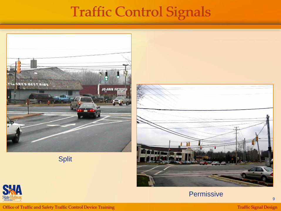
Traffic Control Signals
Permissive
Split
Office of Traffic and Safety Traffic Control Device Training Traffic Signal Design
10
Pedestrian Signals and Devices
Types
At Intersections
Midblock, Pedestrian Crosswalk Signals
Pedestrian Warning Beacons

Office of Traffic and Safety Traffic Control Device Training Traffic Signal Design
11
Pedestrian Signal at Intersections
Pole Mounted Pedestal Mounted
Office of Traffic and Safety Traffic Control Device Training Traffic Signal Design
12
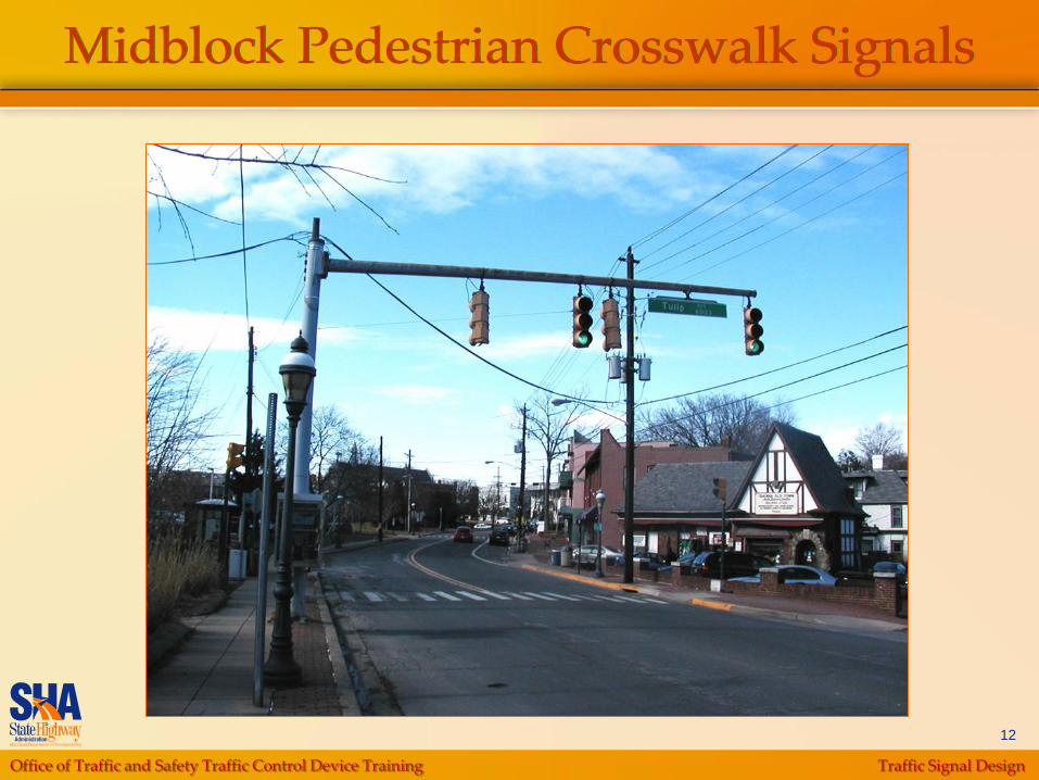
Midblock Pedestrian Crosswalk Signals
Office of Traffic and Safety Traffic Control Device Training Traffic Signal Design
13
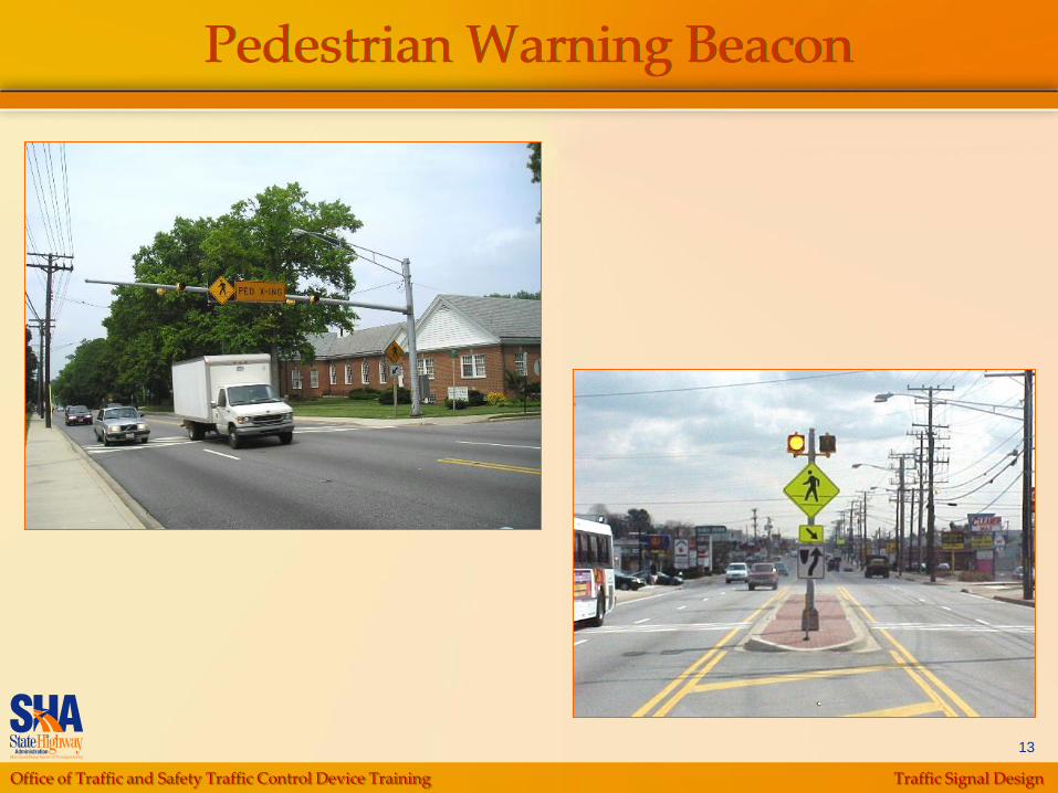
Pedestrian Warning Beacon
Office of Traffic and Safety Traffic Control Device Training Traffic Signal Design
14
Pedestrian Signals and Devices
Special Pedestrian Crossing Devices
Accessible Pedestrian Signal
Countdown Pedestrian Signal
In-Roadway Lights

Office of Traffic and Safety Traffic Control Device Training Traffic Signal Design
15
Accessible Pedestrian Signals(with Illuminating Push Button)

Office of Traffic and Safety Traffic Control Device Training Traffic Signal Design
16
Countdown Pedestrian Signal
The countdown timer starts at the same time as the
flashing “Do Not Walk” starts for pedestrian clearance interval

Office of Traffic and Safety Traffic Control Device Training Traffic Signal Design
17
Special Traffic Control Signals
Flashing Beacons
Intersection Control Beacons (ICBs)
Warning, or Hazard Identification Beacons
(HIBs)
Speed Limit Sign Beacon
Stop Beacon
Emergency Vehicle Access Signals
Office of Traffic and Safety Traffic Control Device Training Traffic Signal Design
18
Intersection Control Beacons
Used at intersections to control two or
more directions
Flashing indications may operate in two
modes:
Yellow for major street and red for all
other approaches or streets
Red for all approaches
Office of Traffic and Safety Traffic Control Device Training Traffic Signal Design
19
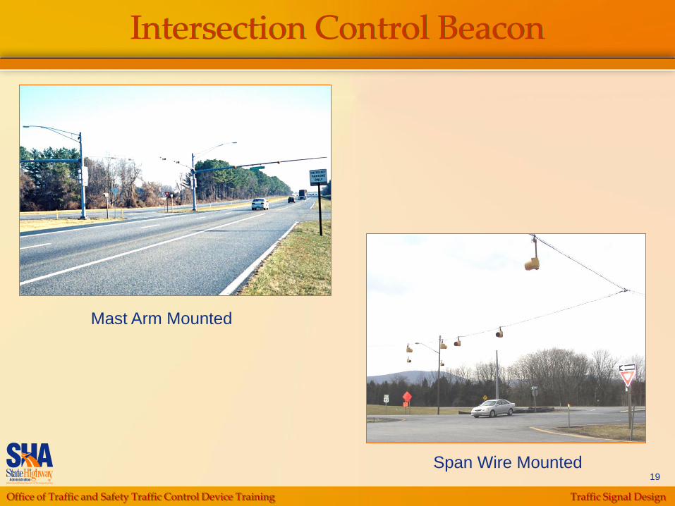
Intersection Control Beacon
Mast Arm Mounted
Span Wire Mounted

Office of Traffic and Safety Traffic Control Device Training Traffic Signal Design
20
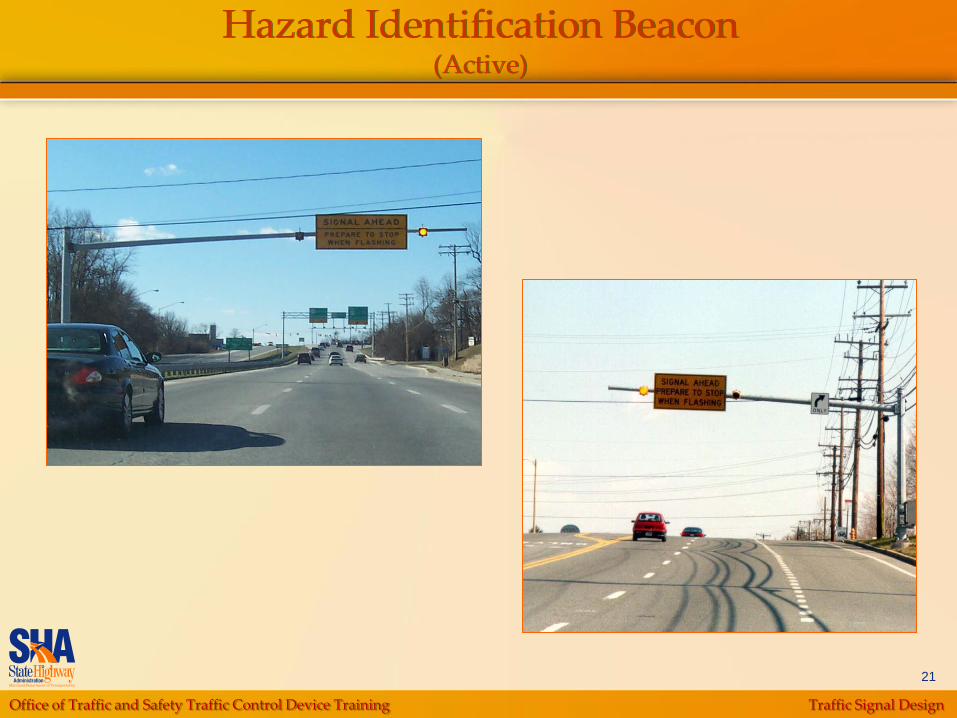
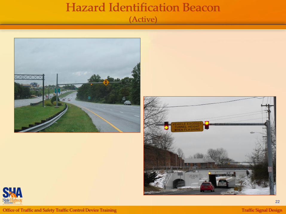
Warning or Hazard Identification Beacons
Used to emphasize warning signs
Alert drivers when obstructions are in or
immediately adjacent to roadway
Active or passive system
Flashing indications are yellow
Office of Traffic and Safety Traffic Control Device Training Traffic Signal Design
21
Hazard Identification Beacon(Active)
Office of Traffic and Safety Traffic Control Device Training Traffic Signal Design
22
Hazard Identification Beacon(Active)

Office of Traffic and Safety Traffic Control Device Training Traffic Signal Design
23
Hazard Identification Beacon(Active)

Office of Traffic and Safety Traffic Control Device Training Traffic Signal Design
24
Hazard Identification Beacon(Passive)
Office of Traffic and Safety Traffic Control Device Training Traffic Signal Design
25
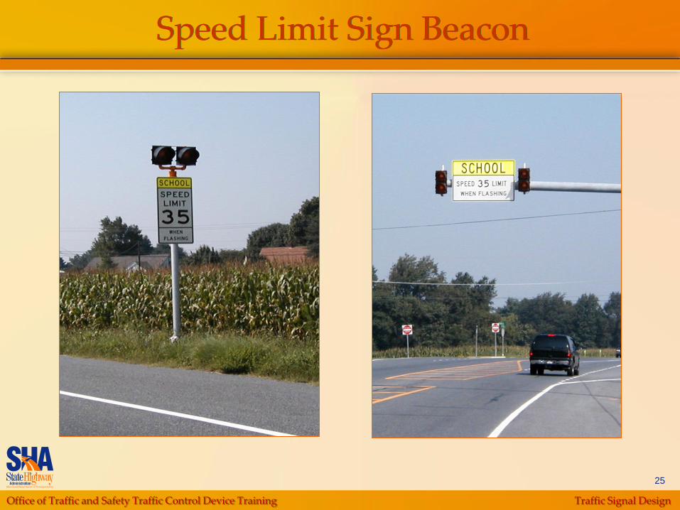
Speed Limit Sign Beacon
Office of Traffic and Safety Traffic Control Device Training Traffic Signal Design
26
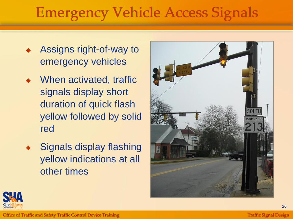
Emergency Vehicle Access Signals
Assigns right-of-way to
emergency vehicles
When activated, traffic
signals display short
duration of quick flash
yellow followed by solid
red
Signals display flashing
yellow indications at all
other times
Office of Traffic and Safety Traffic Control Device Training Traffic Signal Design
27
Special Traffic Control Signals
One Lane, Two-Way Facility
Lane-Use Control Signals
Traffic Control for Movable Bridges
Freeway Entrance Ramp Control Signals

Office of Traffic and Safety Traffic Control Device Training Traffic Signal Design
28
Lane-Use Control Signals
Highway Application
Non-Highway Application
Office of Traffic and Safety Traffic Control Device Training Traffic Signal Design
29
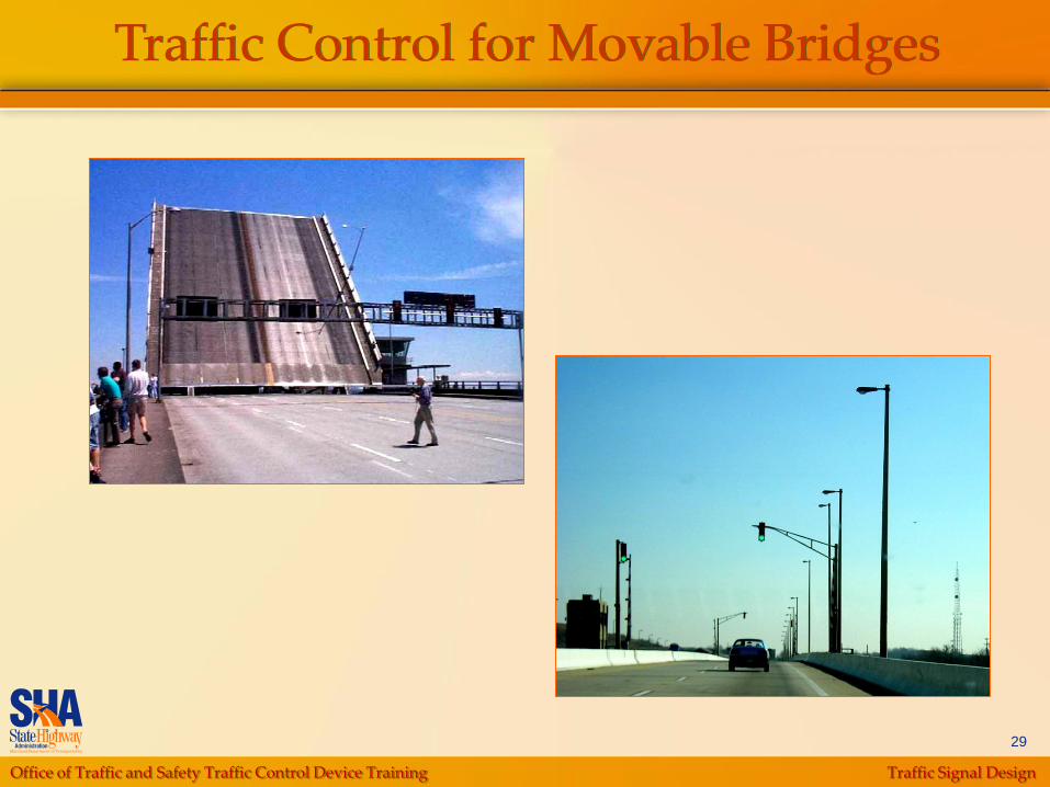
Traffic Control for Movable Bridges
Office of Traffic and Safety Traffic Control Device Training Traffic Signal Design
30
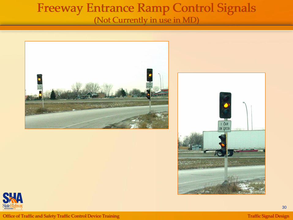
Freeway Entrance Ramp Control Signals(Not Currently in use in MD)

Office of Traffic and Safety Traffic Control Device Training Traffic Signal Design
31
Special Devices
Flag-in-the-Air Intersection Control
Device
Traffic Signal Preemption Unit (Receiver)

Office of Traffic and Safety Traffic Control Device Training Traffic Signal Design
32
Flag-in-the-Air Intersection Control Device
Provides a highly visible control for stopping vehicular
traffic flow at a school-entering and crossing points

Office of Traffic and Safety Traffic Control Device Training Traffic Signal Design
33
Traffic Signal Preemption Unit (Receiver)
The signal controller needs sufficient
time from the emergency vehicle
actuation to change the signal
indications
3 emitters are provided to firehouse

Office of Traffic and Safety Traffic Control Device Training Traffic Signal Design
34
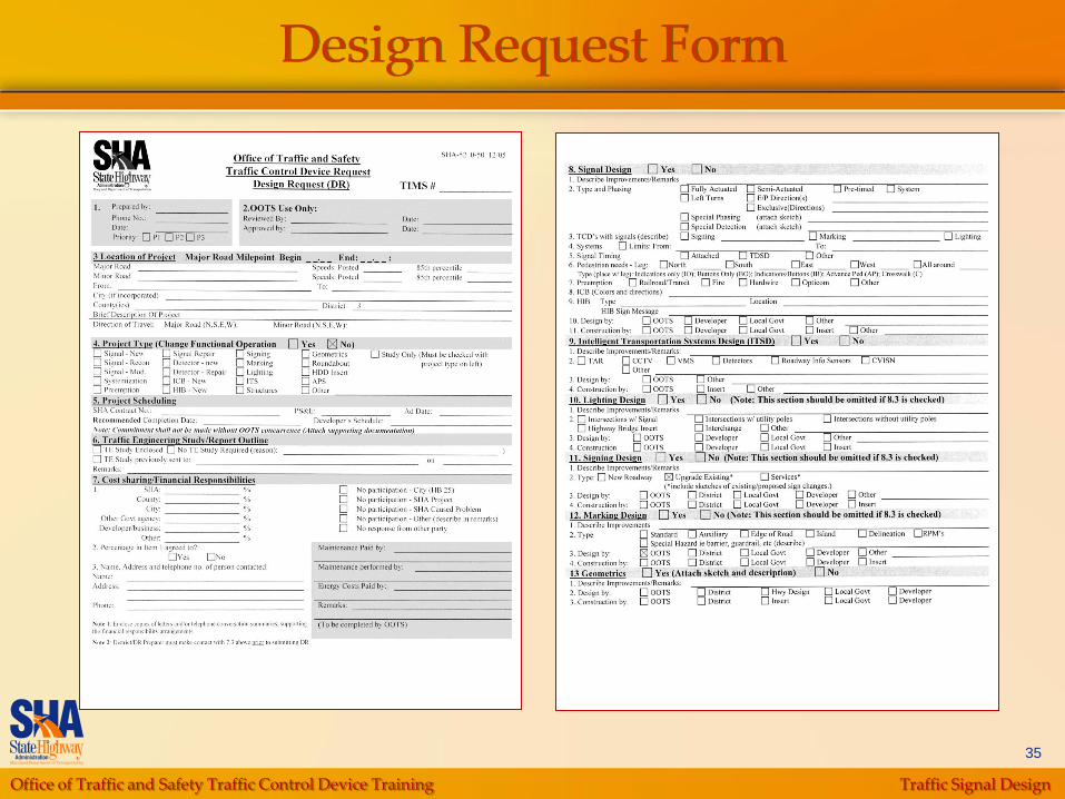
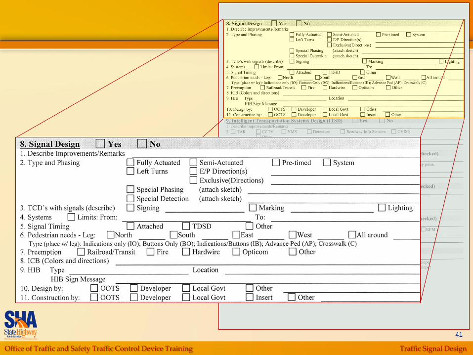
Design Request
Form
Interpretation
Origination
Office of Traffic and Safety Traffic Control Device Training Traffic Signal Design
35
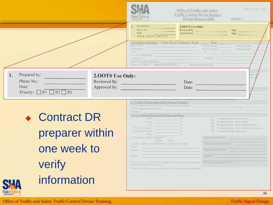
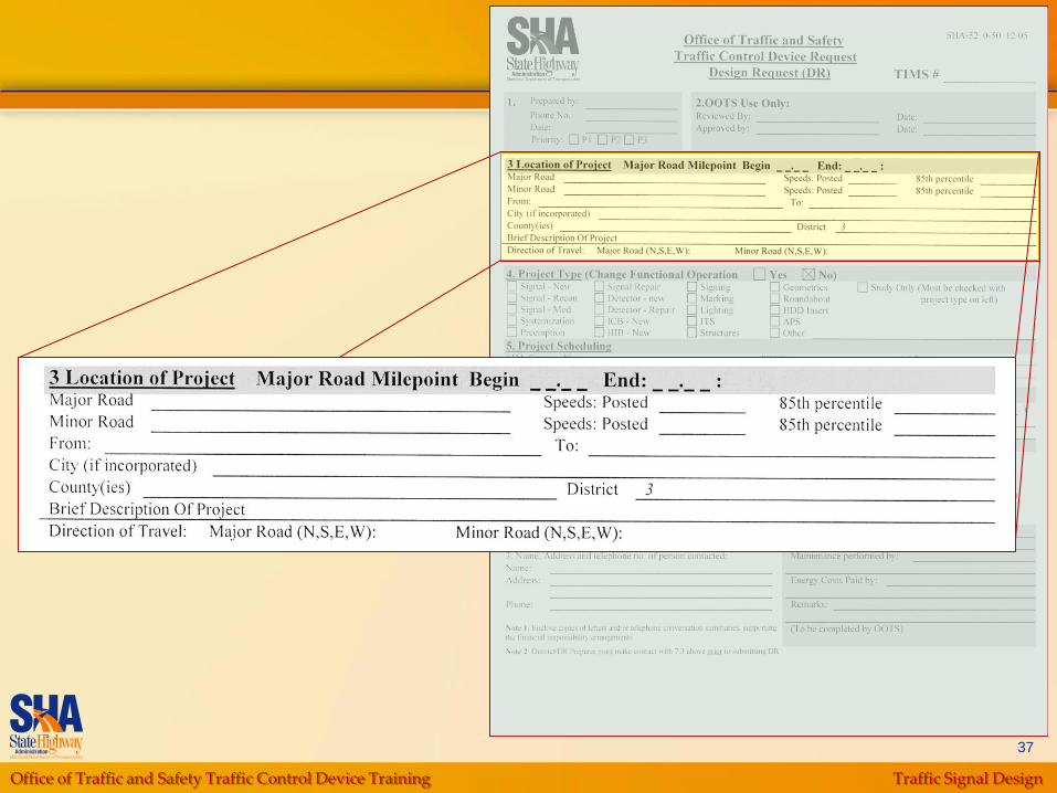
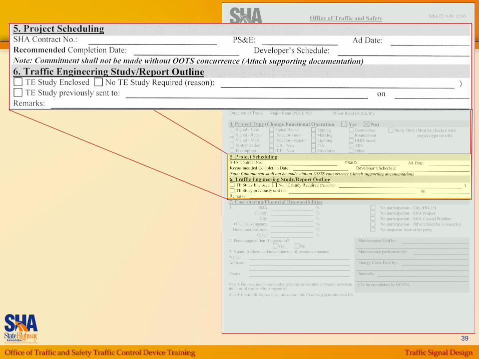
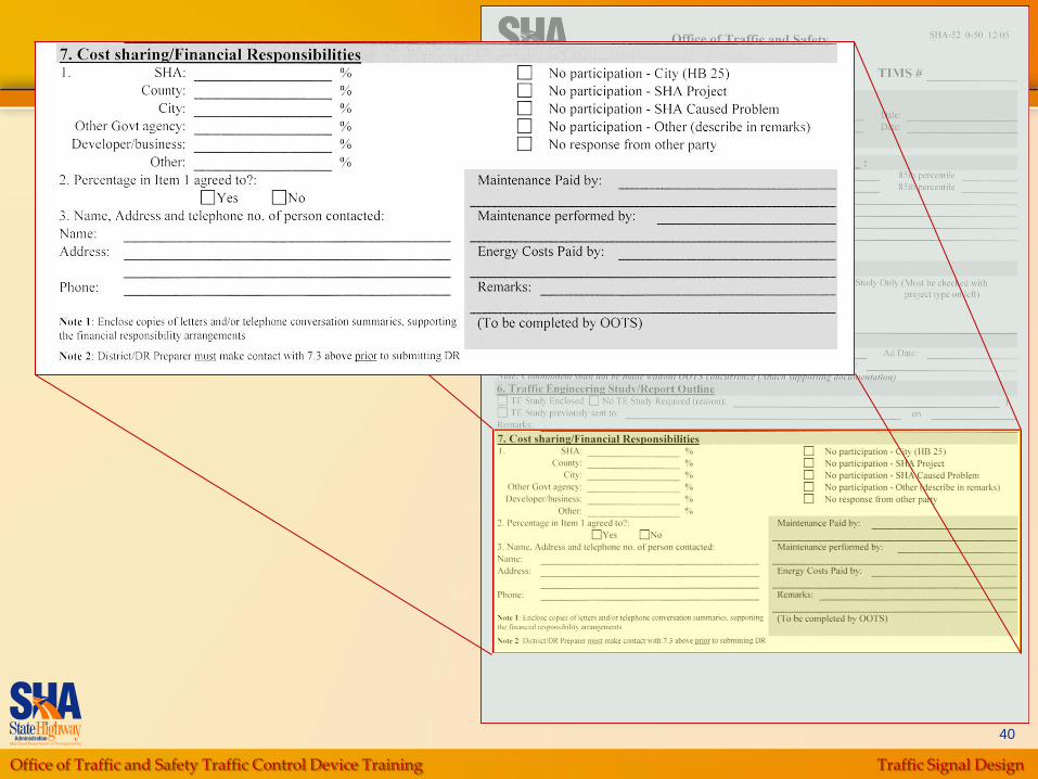
Design Request Form
Office of Traffic and Safety Traffic Control Device Training Traffic Signal Design
36
Contract DR
preparer within
one week to
verify
information
Office of Traffic and Safety Traffic Control Device Training Traffic Signal Design
37

Office of Traffic and Safety Traffic Control Device Training Traffic Signal Design
38
Office of Traffic and Safety Traffic Control Device Training Traffic Signal Design
39
Office of Traffic and Safety Traffic Control Device Training Traffic Signal Design
40
Office of Traffic and Safety Traffic Control Device Training Traffic Signal Design
41

Office of Traffic and Safety Traffic Control Device Training Traffic Signal Design
42
Standards and Guidelines
Manual on Uniform
Traffic Control Devices
(MUTCD)
Application and
Placement
of Regulatory, Warning,
Guide Signs, Traffic
Signals and other
Devices
For traffic signal design:
provides information on
visibility, type of
displays, and
maintenance
Office of Traffic and Safety Traffic Control Device Training Traffic Signal Design
43
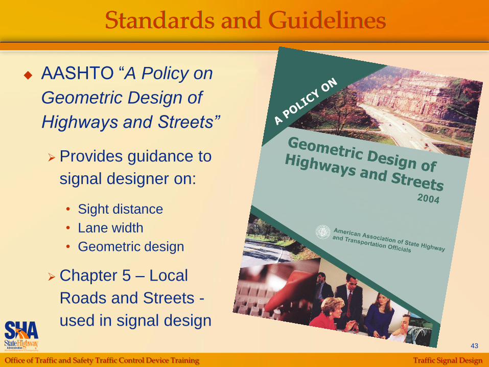
AASHTO “A Policy on
Geometric Design of
Highways and Streets”
Provides guidance to
signal designer on:
• Sight distance
• Lane width
• Geometric design
Chapter 5 – Local
Roads and Streets -
used in signal design
Standards and Guidelines
Office of Traffic and Safety Traffic Control Device Training Traffic Signal Design
44
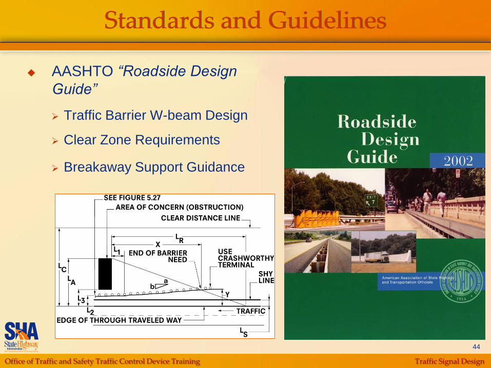
Standards and Guidelines
AASHTO “Roadside Design
Guide”
Traffic Barrier W-beam Design
Clear Zone Requirements
Breakaway Support Guidance
Office of Traffic and Safety Traffic Control Device Training Traffic Signal Design
45
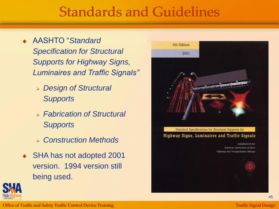
Standards and Guidelines
AASHTO “Standard
Specification for Structural
Supports for Highway Signs,
Luminaires and Traffic Signals”
Design of Structural
Supports
Fabrication of Structural
Supports
Construction Methods
SHA has not adopted 2001
version. 1994 version still
being used.
Office of Traffic and Safety Traffic Control Device Training Traffic Signal Design
46
Standards and Guidelines
SHA – Design Guidelines
SHA‟s Maryland Manual on Uniform Traffic Control
Devices
SHA’s Standard Sign Book
SHA‟s Accessibility Guidelines for Pedestrian Facilities
along State Highways
SHA‟s Guidelines for Traffic Barrier Placement and
End Treatment Design
SHA’s Traffic Control Devices Design Manual
SHA‟s CADD Users Guide
Office of Traffic and Safety Traffic Control Device Training Traffic Signal Design
47
Standards and Guidelines
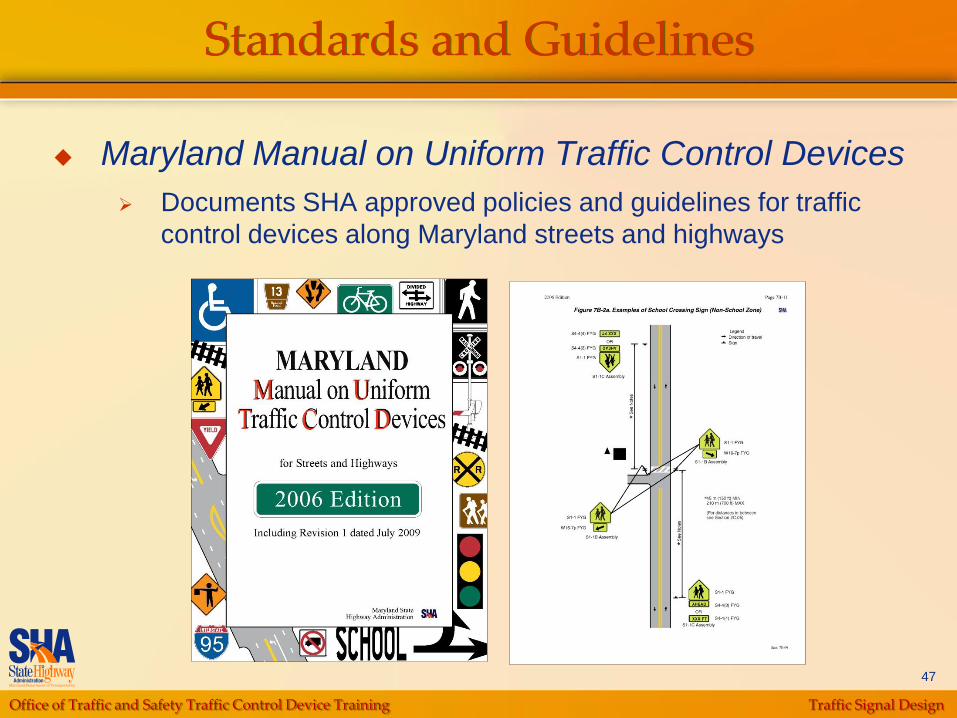
Maryland Manual on Uniform Traffic Control Devices
Documents SHA approved policies and guidelines for traffic
control devices along Maryland streets and highways
Office of Traffic and Safety Traffic Control Device Training Traffic Signal Design
48
Standards and Guidelines
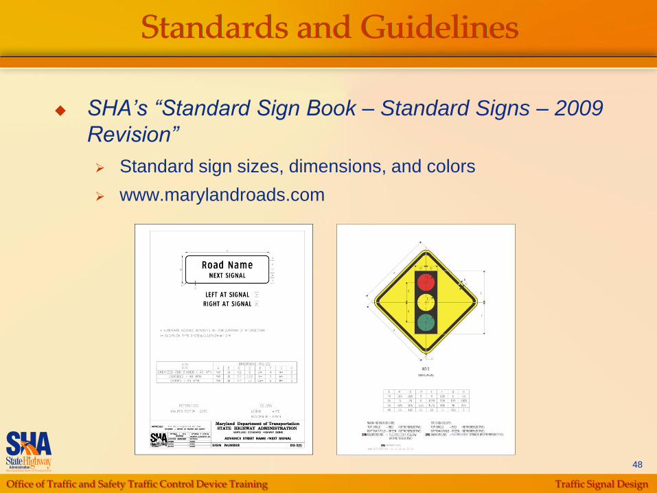
SHA’s “Standard Sign Book – Standard Signs – 2009
Revision”
Standard sign sizes, dimensions, and colors
www.marylandroads.com

Office of Traffic and Safety Traffic Control Device Training Traffic Signal Design
49
Standards and Guidelines
SHA “Accessibility Guidelines
for Pedestrian Facilities along
State Highways”
Developed to create
accessible routes through
design of public sidewalks
and crossings
Provides guidance on
installation of signal-related
hardware such as:
• Cabinet
• Poles
• Pushbuttons
Provides guidance on use
and design of Accessible
Pedestrian Signals (APS)
Office of Traffic and Safety Traffic Control Device Training Traffic Signal Design
50
Standards and Guidelines
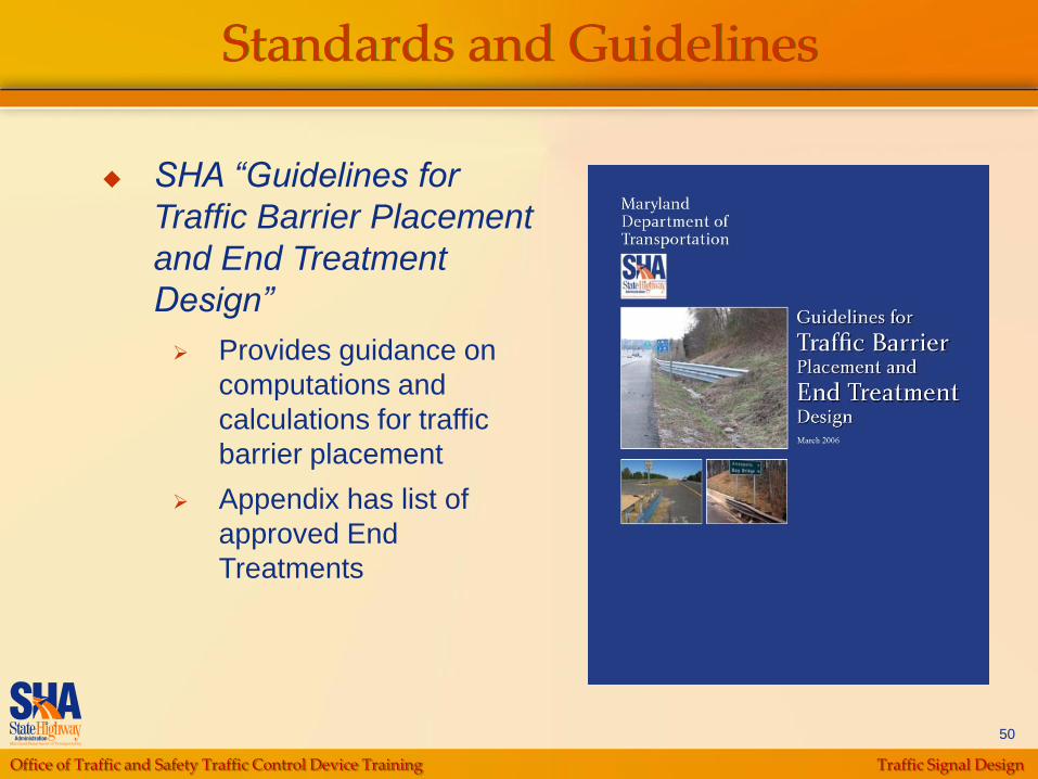
SHA “Guidelines for
Traffic Barrier Placement
and End Treatment
Design”
Provides guidance on
computations and
calculations for traffic
barrier placement
Appendix has list of
approved End
Treatments

Office of Traffic and Safety Traffic Control Device Training Traffic Signal Design
51
Standards and Guidelines
SHA – Standards and Specifications
SHA’s Book of Standards
SHA‟s Standard Specifications for
Construction and Materials and General
Provisions for Construction Contracts, Part III
SHA‟s Special Provisions Inserts, Special
Provisions OOTS Shelf Specs and
Engineering Change Notices by OOTS
Office of Traffic and Safety Traffic Control Device Training Traffic Signal Design
52
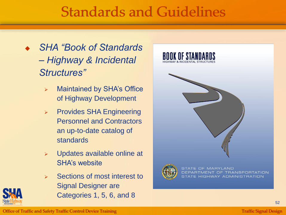
Standards and Guidelines
SHA “Book of Standards
– Highway & Incidental
Structures”
Maintained by SHA‟s Office
of Highway Development
Provides SHA Engineering
Personnel and Contractors
an up-to-date catalog of
standards
Updates available online at
SHA‟s website
Sections of most interest to
Signal Designer are
Categories 1, 5, 6, and 8

Office of Traffic and Safety Traffic Control Device Training Traffic Signal Design
53
Standards and Guidelines
SHA “Standard Specifications
(Gray Book)”
Specifications
• Description
• Materials
• Construction
• Measurement and Payment
Sections of Most Interest to
Signal Designer:
• Category 100 – Preliminary
• Category 500 – Paving
• Category 600 – Shoulders
• Category 800 – Traffic
Office of Traffic and Safety Traffic Control Device Training Traffic Signal Design
54
Standards and Guidelines
Electrical Safety
Maryland High-Voltage Line Act: Article 89,
§ 58-63, Annotated Code of Maryland
National Electrical Code (NEC)
National Electrical Safety Code (NESC)
Office of Traffic and Safety Traffic Control Device Training Traffic Signal Design
55
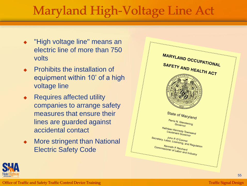
Maryland High-Voltage Line Act
"High voltage line" means an
electric line of more than 750
volts
Prohibits the installation of
equipment within 10‟ of a high
voltage line
Requires affected utility
companies to arrange safety
measures that ensure their
lines are guarded against
accidental contact
More stringent than National
Electric Safety Code
Office of Traffic and Safety Traffic Control Device Training Traffic Signal Design
56
National Electrical Code (NEC) 2008
A standard published by the
National Fire Protection
Association (NFPA) and
incorporated in OSHA regulations
Provides guidance on the
installation of conductors and
equipment that connect to the
supply of electricity
NEC is revised on a three-year
cycle
2008 edition is the latest
Frequently, the Maryland High
Voltage Line Act requirements are
more stringent
Office of Traffic and Safety Traffic Control Device Training Traffic Signal Design
57
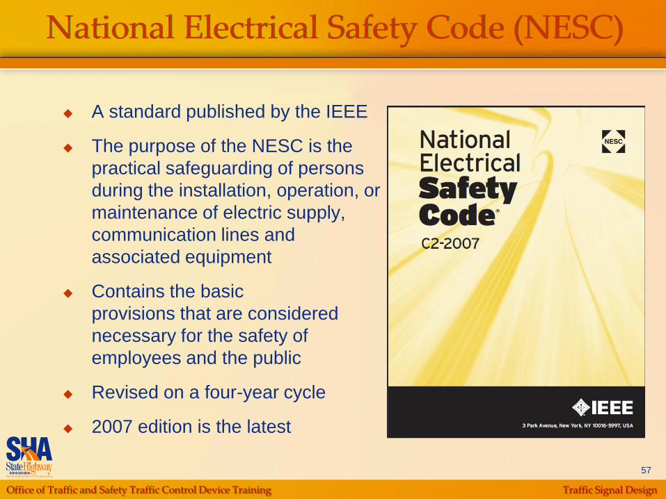
National Electrical Safety Code (NESC)
A standard published by the IEEE
The purpose of the NESC is the
practical safeguarding of persons
during the installation, operation, or
maintenance of electric supply,
communication lines and
associated equipment
Contains the basic
provisions that are considered
necessary for the safety of
employees and the public
Revised on a four-year cycle
2007 edition is the latest

Office of Traffic and Safety Traffic Control Device Training Traffic Signal Design
58
Office Data Collection
Latest Signal Plan(s) from TEDD
Electronic Files Preferred
Highway Design Plans
Existing and Proposed
Right-of Way Information
Send Memo to Request Right-of-Way
• Two memos if County Right-of-Way required
Utility Plans
Utility Companies
Local Municipalities
Locator Services

Office of Traffic and Safety Traffic Control Device Training Traffic Signal Design
59
Initial Site Visit
Field Survey Equipment
Verify and Collect Existing Information
Field Survey Data
Tape and Wheel Measurements
Overhead Utility Heights
Signal Visibility
Office of Traffic and Safety Traffic Control Device Training Traffic Signal Design
60
Field Survey Equipment
Safety Vest
Gloves (Waterproof)
Tape Measure
Measuring Wheel
Cable Height
Measuring Rod
Digital Camera
Hand Level
Two-Way Radios
Screwdrivers (Flathead
and Phillips)
Pick
Pliers
Flashlight
Spray Paint Can
Waterproof Chalk
Control Cabinet Key
Office of Traffic and Safety Traffic Control Device Training Traffic Signal Design
61
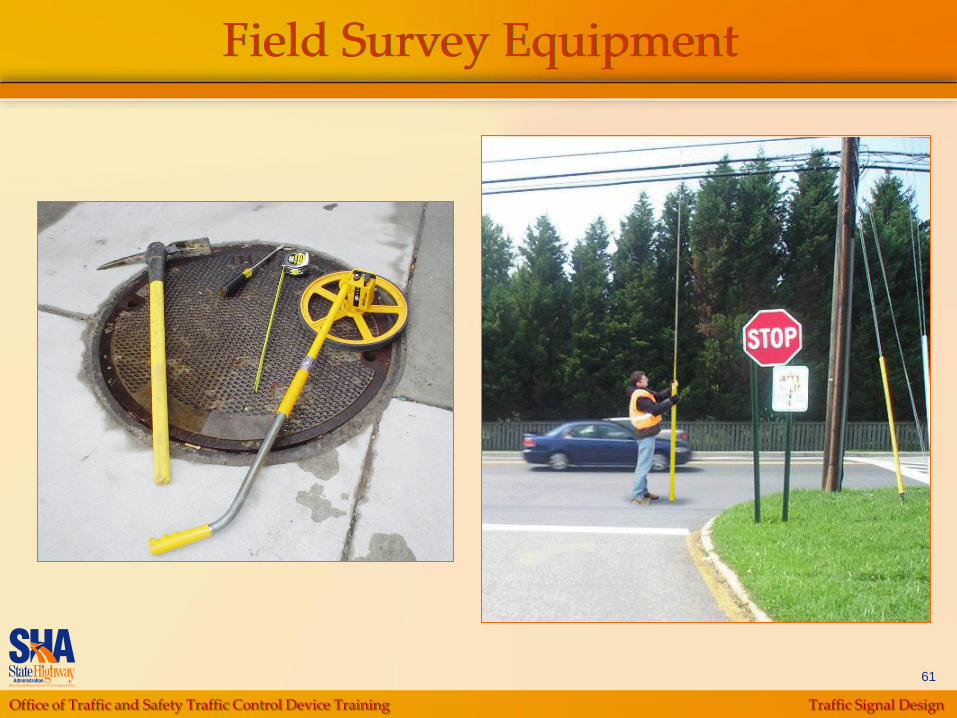
Field Survey Equipment
Office of Traffic and Safety Traffic Control Device Training Traffic Signal Design
62
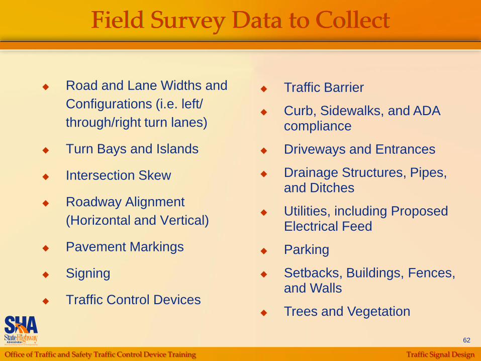
Field Survey Data to Collect
Road and Lane Widths and
Configurations (i.e. left/
through/right turn lanes)
Turn Bays and Islands
Intersection Skew
Roadway Alignment
(Horizontal and Vertical)
Pavement Markings
Signing
Traffic Control Devices
Traffic Barrier
Curb, Sidewalks, and ADA compliance
Driveways and Entrances
Drainage Structures, Pipes, and Ditches
Utilities, including Proposed Electrical Feed
Parking
Setbacks, Buildings, Fences, and Walls
Trees and Vegetation
Office of Traffic and Safety Traffic Control Device Training Traffic Signal Design
63
Tape and Wheel Survey
Create sketch of intersection
For signalized intersections, note locations
of signal supports and heads
For unsignalized intersections, note
potential locations of signal supports
Office of Traffic and Safety Traffic Control Device Training Traffic Signal Design
64
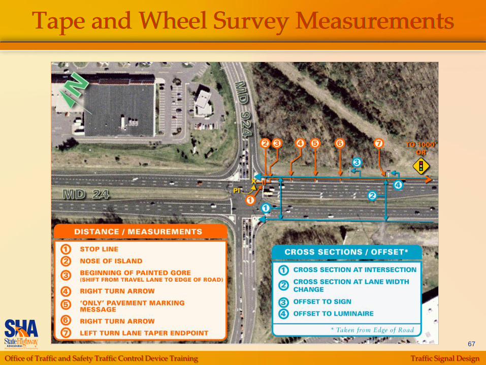
Tape and Wheel Survey
Distances/Offsets (See Tab #2 for Instructions) Locate Point of Intersection (PI) at 1st leg of intersection
Record distance from PI to surface features using
measuring wheel
Continue measuring for a distance of 1,000‟ or to
Signal Ahead sign (W3-3)
Measure offset to recorded features from edge of
roadway using cloth tape while walking back toward the
intersection
Repeat steps for the other legs of intersection and for
medians
Office of Traffic and Safety Traffic Control Device Training Traffic Signal Design
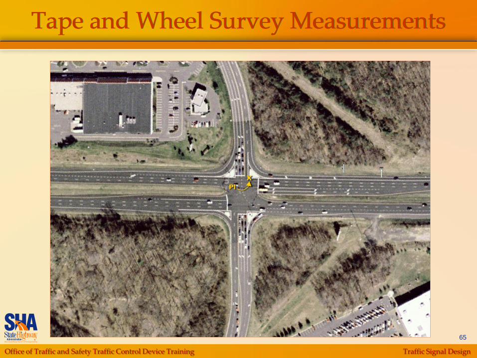
65
Tape and Wheel Survey Measurements
Office of Traffic and Safety Traffic Control Device Training Traffic Signal Design
66
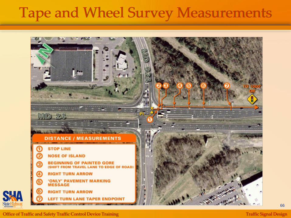
Tape and Wheel Survey Measurements
Office of Traffic and Safety Traffic Control Device Training Traffic Signal Design
67
Tape and Wheel Survey Measurements

Office of Traffic and Safety Traffic Control Device Training Traffic Signal Design
68
Tape and Wheel Survey Measurements
Office of Traffic and Safety Traffic Control Device Training Traffic Signal Design
69
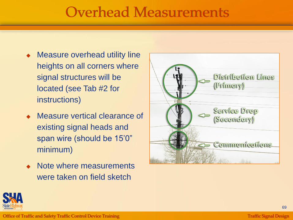
Overhead Measurements
Measure overhead utility line
heights on all corners where
signal structures will be
located (see Tab #2 for
instructions)
Measure vertical clearance of
existing signal heads and
span wire (should be 15‟0”
minimum)
Note where measurements
were taken on field sketch
Office of Traffic and Safety Traffic Control Device Training Traffic Signal Design
70
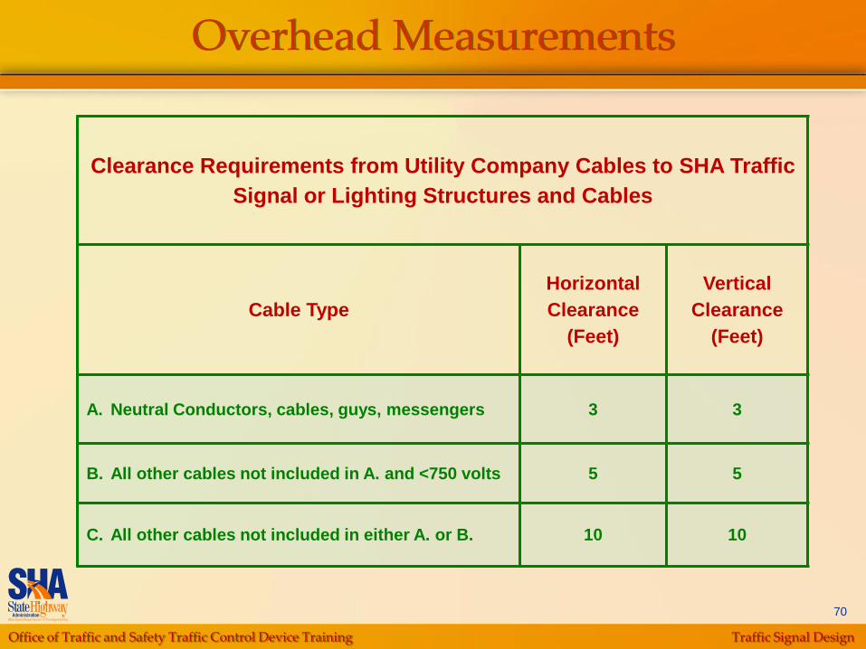
Overhead Measurements
Clearance Requirements from Utility Company Cables to SHA Traffic
Signal or Lighting Structures and Cables
Cable Type
Horizontal
Clearance
(Feet)
Vertical
Clearance
(Feet)
A. Neutral Conductors, cables, guys, messengers 3 3
B. All other cables not included in A. and <750 volts 5 5
C. All other cables not included in either A. or B. 10 10

Office of Traffic and Safety Traffic Control Device Training Traffic Signal Design
71
Skew Measurements
For quadrants that do not intersect at 90 , use
the form provided in Tab #2 to record the
appropriate measurements
Office of Traffic and Safety Traffic Control Device Training Traffic Signal Design
72
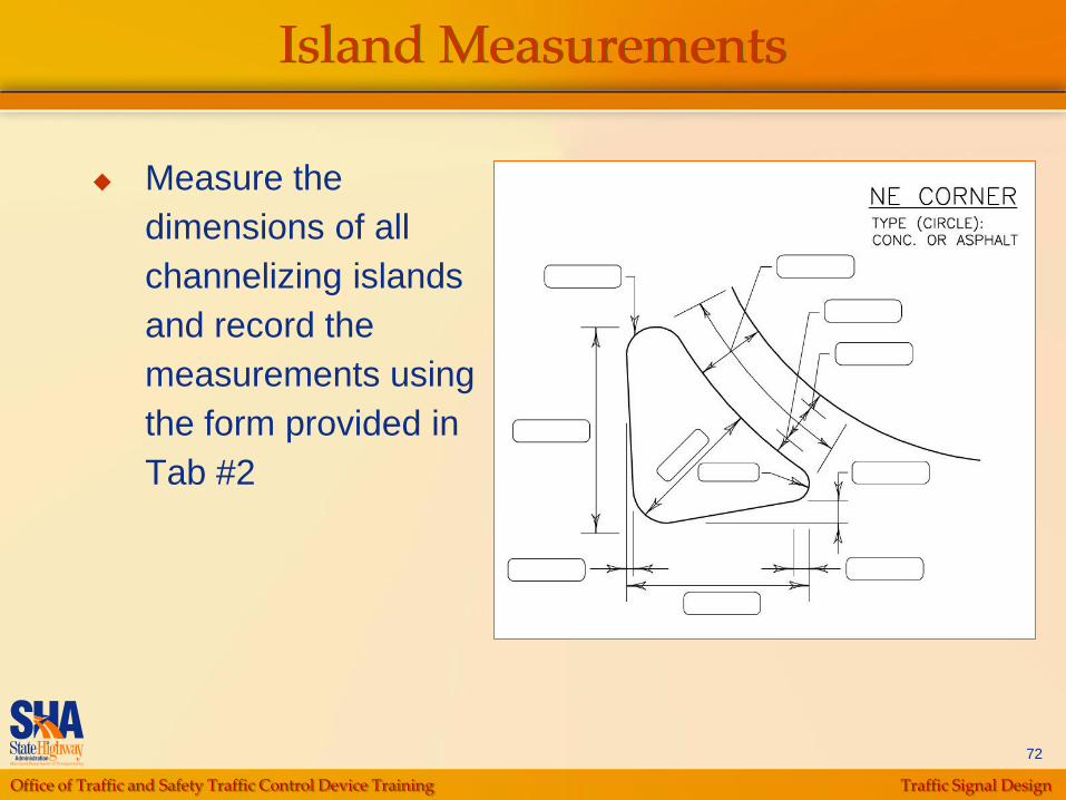
Island Measurements
Measure the
dimensions of all
channelizing islands
and record the
measurements using
the form provided in
Tab #2
Office of Traffic and Safety Traffic Control Device Training Traffic Signal Design
73
Signal Visibility Measurements
Measured on approaches where roadway
curvature or other site features create restriction
visibility
Use a two-way radio or cell phone for
communications during this step
Make visibility observations at 100‟ increments,
measured from the STOP line
Office of Traffic and Safety Traffic Control Device Training Traffic Signal Design
74
Signal Visibility Measurements
First person: hold the measuring rod, extended to a
height of 18‟6” (the normal center of a signal head)
at the approximate location of either the left or right
through-traffic signal head, whichever provides the
best visibility
Second person: make the observations with eye
level at approximately 3‟6” (driver eye height) from
the middle-left side of the lane that has the most
restricted sight distance
Office of Traffic and Safety Traffic Control Device Training Traffic Signal Design
75
Signal Visibility Measurements
Record the distance where the top of rod is no
longer visible and compare it to the minimum sight
distance for the prevailing speed of the road
(assume 10 MPH over the posted speed if not
designated in the DR)
If the sight distance is less than required, set up the
rod at a location where the required visibility can be
achieved and where it is feasible to mount a signal
head

Office of Traffic and Safety Traffic Control Device Training Traffic Signal Design
76
Signal Visibility Measurements
Office of Traffic and Safety Traffic Control Device Training Traffic Signal Design
77
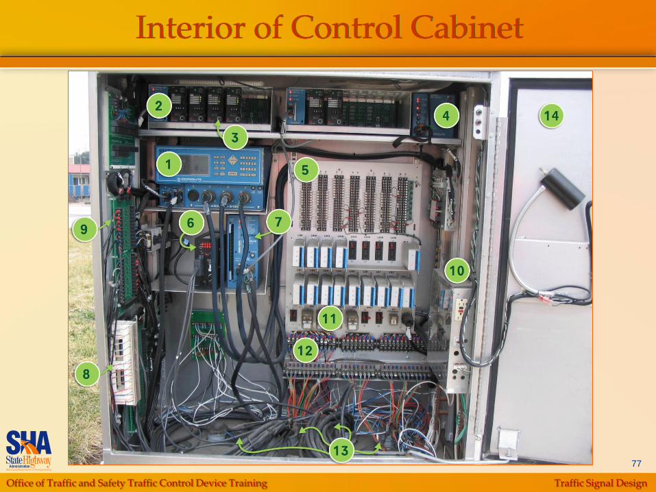
Interior of Control Cabinet
Office of Traffic and Safety Traffic Control Device Training Traffic Signal Design
78
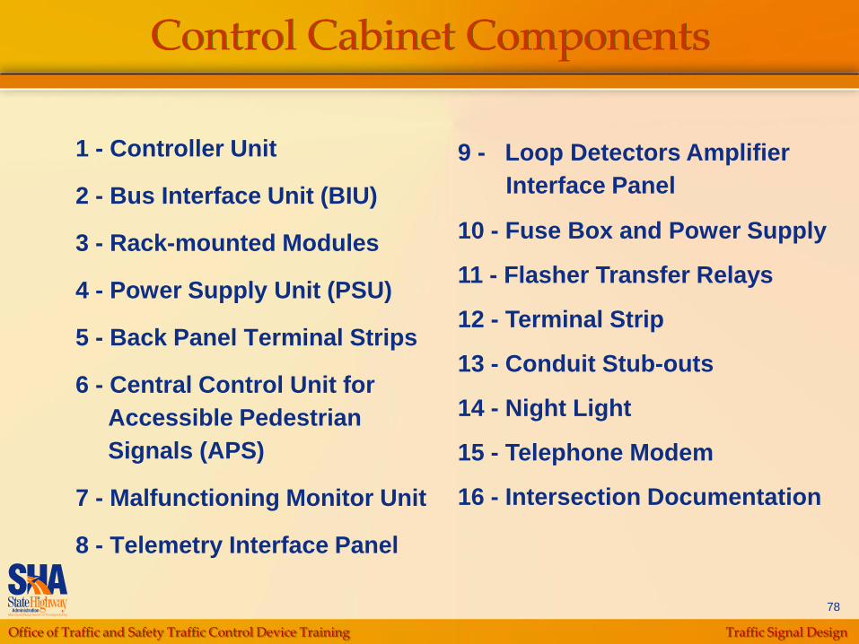
Control Cabinet Components
1 - Controller Unit
2 - Bus Interface Unit (BIU)
3 - Rack-mounted Modules
4 - Power Supply Unit (PSU)
5 - Back Panel Terminal Strips
6 - Central Control Unit for
Accessible Pedestrian
Signals (APS)
7 - Malfunctioning Monitor Unit
8 - Telemetry Interface Panel
9 - Loop Detectors Amplifier
Interface Panel
10 - Fuse Box and Power Supply
11 - Flasher Transfer Relays
12 - Terminal Strip
13 - Conduit Stub-outs
14 - Night Light
15 - Telephone Modem
16 - Intersection Documentation
Office of Traffic and Safety Traffic Control Device Training Traffic Signal Design
79
Base Mounted vs. Pole Mounted
Base Mounted
Preferred for all new traffic signals
Sufficient space for all control equipment
Provides flexibility for additional control equipment in future
Pole Mounted
Consider if there is right-of-way constraints for new signals
Preferred for temporary traffic signals

Office of Traffic and Safety Traffic Control Device Training Traffic Signal Design
80
Signal Control Unit
Keypad for entering
information
Connectors
“A” – Provides power to
controller. As well as Inputs
and Outputs (I/O) to cabinet
“B” & “C” – Provide various
Inputs and Outputs (I/O) for
intersection control
“D” – Provides
communication, preemption
and expanded detection
capabilities
Office of Traffic and Safety Traffic Control Device Training Traffic Signal Design
81
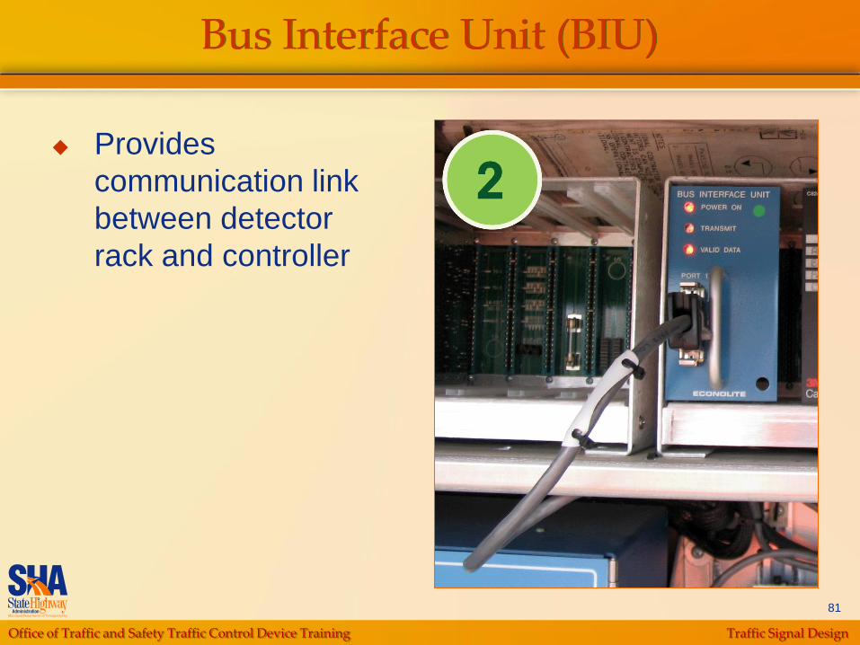
Bus Interface Unit (BIU)
Provides
communication link
between detector
rack and controller
Office of Traffic and Safety Traffic Control Device Training Traffic Signal Design
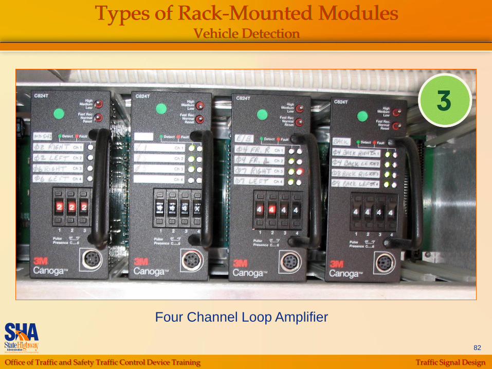
82
Types of Rack-Mounted ModulesVehicle Detection
Four Channel Loop Amplifier
Office of Traffic and Safety Traffic Control Device Training Traffic Signal Design
83
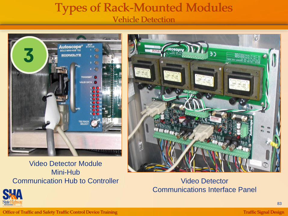
Types of Rack-Mounted ModulesVehicle Detection
Video Detector Module
Mini-Hub
Communication Hub to Controller Video Detector
Communications Interface Panel
Office of Traffic and Safety Traffic Control Device Training Traffic Signal Design
84
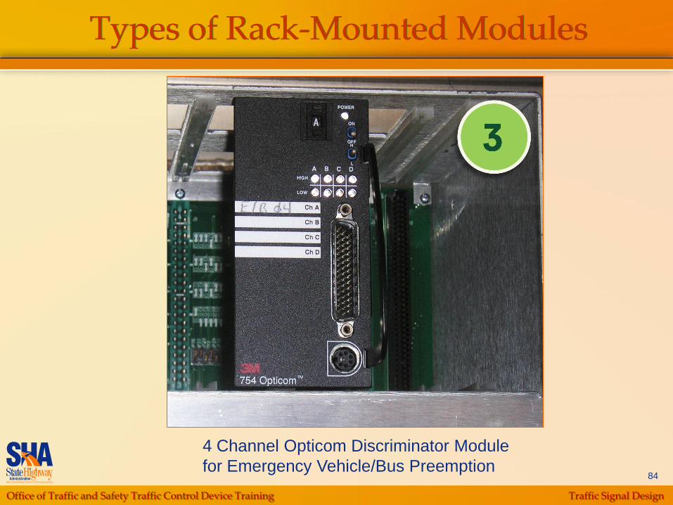
Types of Rack-Mounted Modules
4 Channel Opticom Discriminator Module
for Emergency Vehicle/Bus Preemption

Office of Traffic and Safety Traffic Control Device Training Traffic Signal Design
85
External Power Supply Unit
Supplies 24V DC
power to the Loop
Amplifier Rack

Office of Traffic and Safety Traffic Control Device Training Traffic Signal Design
86
Back Panel Terminal Strips
Wiring terminals to hard-wire Inputs/Outputs for the
controller
Low Voltage (DC)
Office of Traffic and Safety Traffic Control Device Training Traffic Signal Design
87
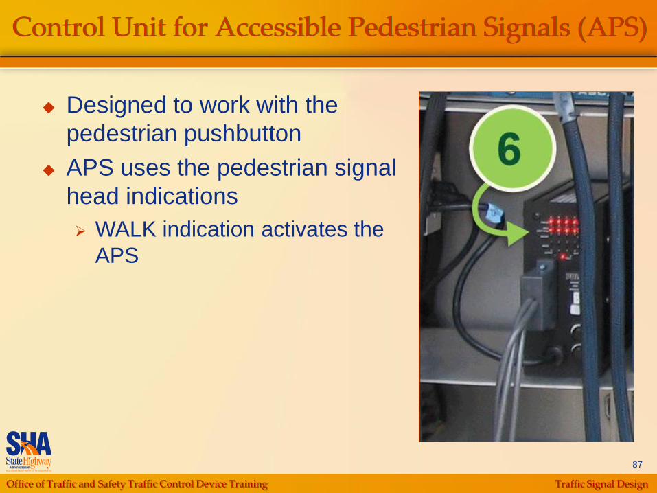
Control Unit for Accessible Pedestrian Signals (APS)
Designed to work with the
pedestrian pushbutton
APS uses the pedestrian signal
head indications
WALK indication activates the
APS
Office of Traffic and Safety Traffic Control Device Training Traffic Signal Design
88
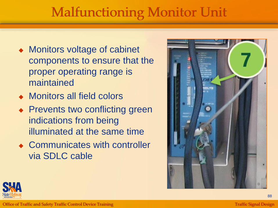
Malfunctioning Monitor Unit
Monitors voltage of cabinet
components to ensure that the
proper operating range is
maintained
Monitors all field colors
Prevents two conflicting green
indications from being
illuminated at the same time
Communicates with controller
via SDLC cable
Office of Traffic and Safety Traffic Control Device Training Traffic Signal Design
89
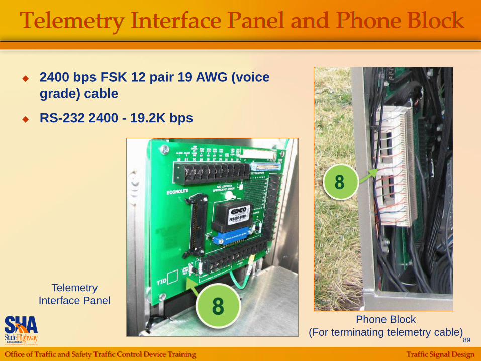
Telemetry Interface Panel and Phone Block
2400 bps FSK 12 pair 19 AWG (voice
grade) cable
RS-232 2400 - 19.2K bps
Telemetry
Interface Panel
Phone Block
(For terminating telemetry cable)
Office of Traffic and Safety Traffic Control Device Training Traffic Signal Design
90
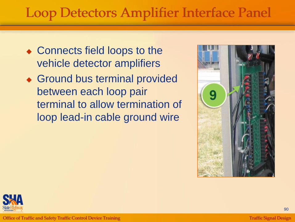
Loop Detectors Amplifier Interface Panel
Connects field loops to the
vehicle detector amplifiers
Ground bus terminal provided
between each loop pair
terminal to allow termination of
loop lead-in cable ground wire
Office of Traffic and Safety Traffic Control Device Training Traffic Signal Design
91
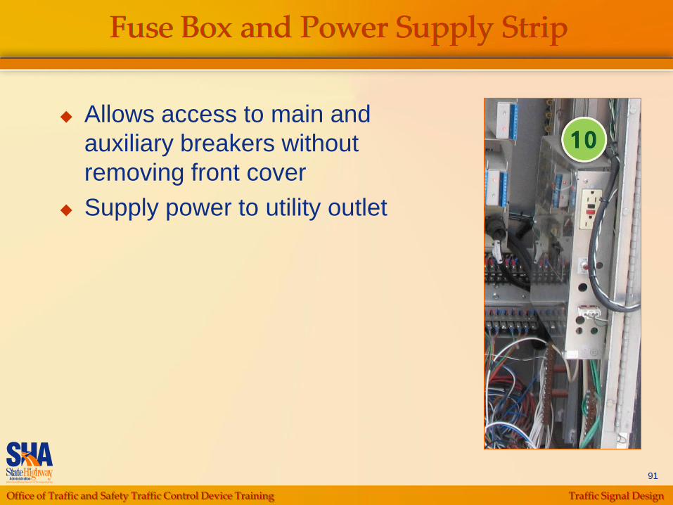
Fuse Box and Power Supply Strip
Allows access to main and
auxiliary breakers without
removing front cover
Supply power to utility outlet
Office of Traffic and Safety Traffic Control Device Training Traffic Signal Design
92
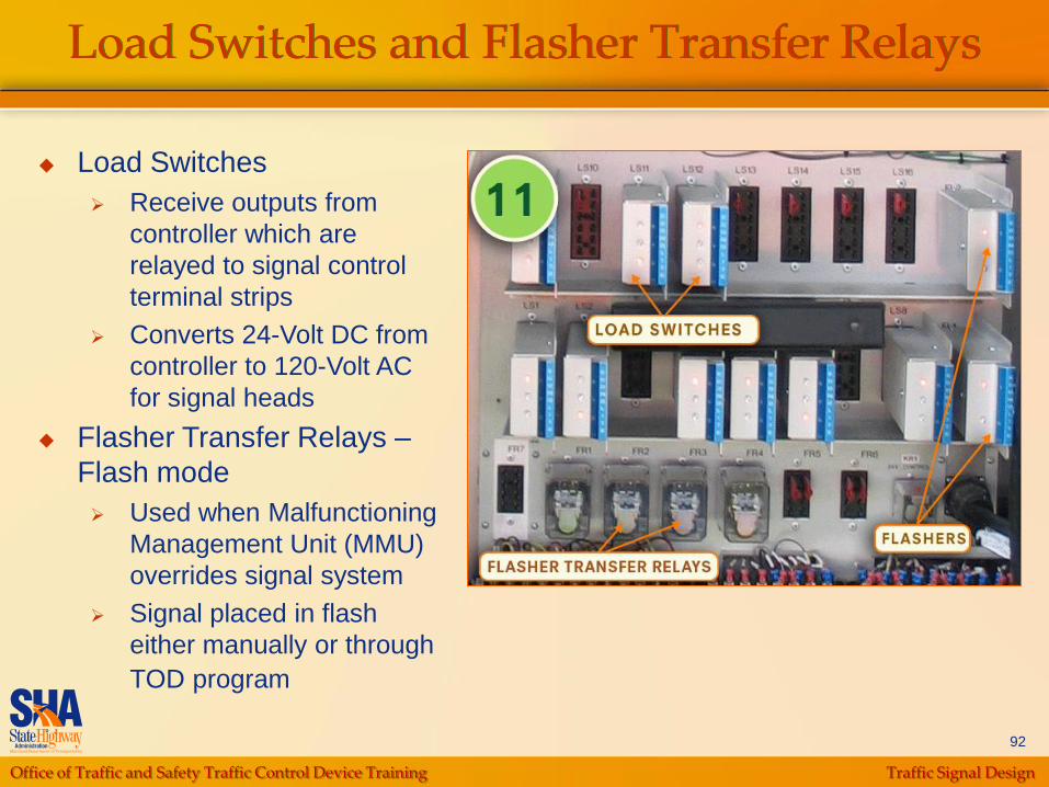
Load Switches and Flasher Transfer Relays
Load Switches
Receive outputs from
controller which are
relayed to signal control
terminal strips
Converts 24-Volt DC from
controller to 120-Volt AC
for signal heads
Flasher Transfer Relays –
Flash mode
Used when Malfunctioning
Management Unit (MMU)
overrides signal system
Signal placed in flash
either manually or through
TOD program
Office of Traffic and Safety Traffic Control Device Training Traffic Signal Design
93
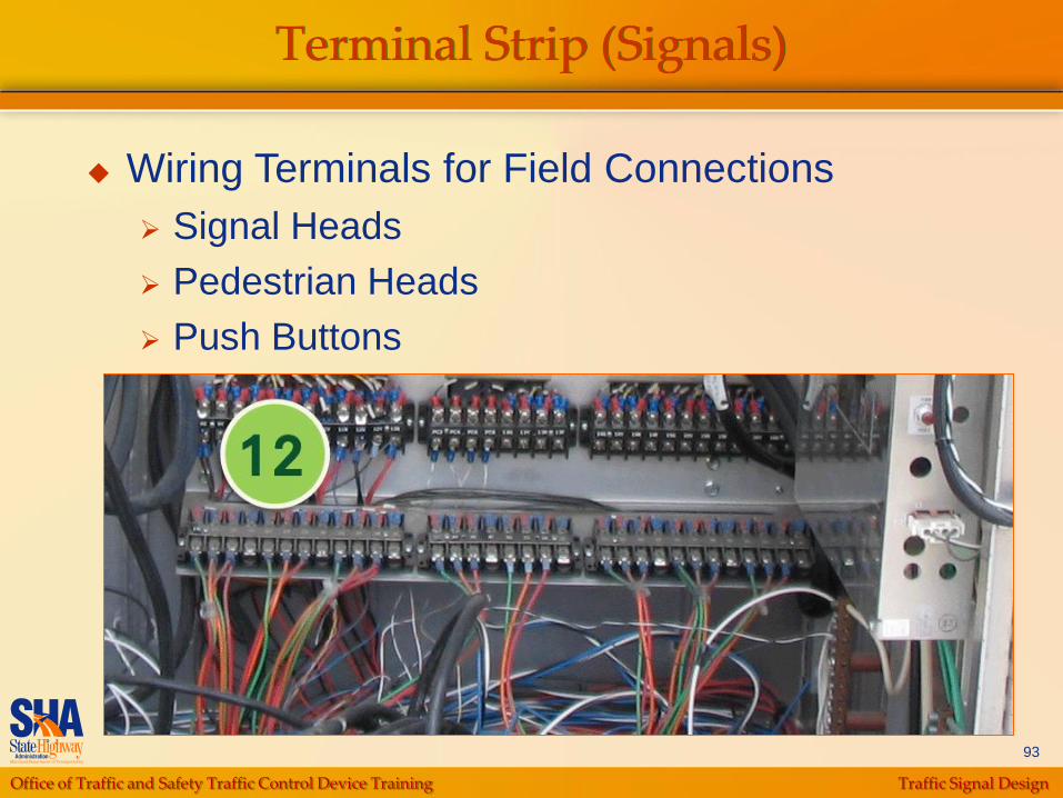
Terminal Strip (Signals)
Wiring Terminals for Field Connections
Signal Heads
Pedestrian Heads
Push Buttons
Office of Traffic and Safety Traffic Control Device Training Traffic Signal Design
94
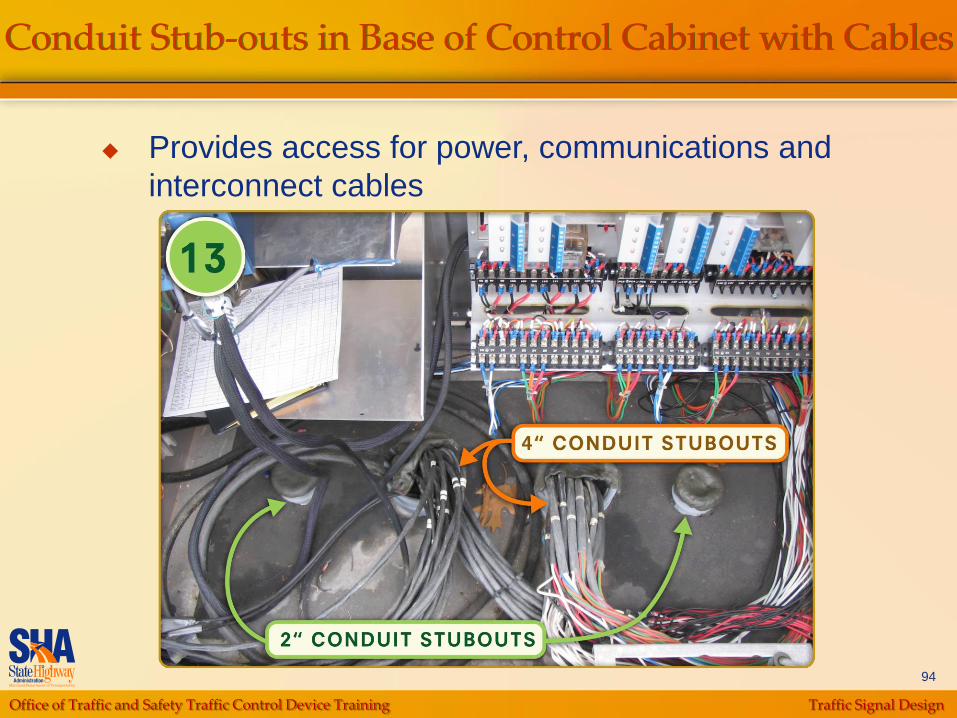
Conduit Stub-outs in Base of Control Cabinet with Cables
Provides access for power, communications and
interconnect cables
Office of Traffic and Safety Traffic Control Device Training Traffic Signal Design
95
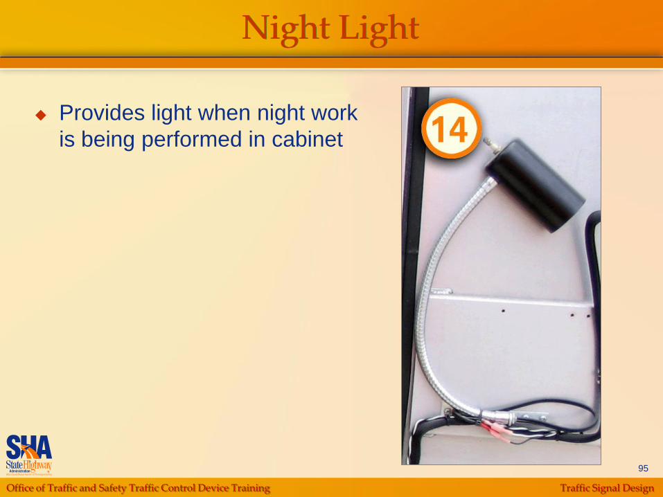
Night Light
Provides light when night work
is being performed in cabinet

Office of Traffic and Safety Traffic Control Device Training Traffic Signal Design
96
Telephone Modem
Provides communications
access from remote
location enabling SHA to
control and monitor
intersection operations
Office of Traffic and Safety Traffic Control Device Training Traffic Signal Design
97
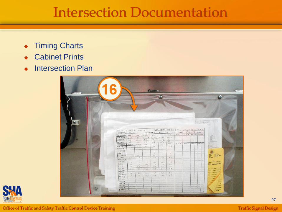
Intersection Documentation
Timing Charts
Cabinet Prints
Intersection Plan
Office of Traffic and Safety Traffic Control Device Training Traffic Signal Design
98
Conduit and Cabling System Documentation(For Rebuild Projects)
Verify additional cables can be placed in
conduit by visual observation
Verify conduit is not blocked/crushed by using
chalk method to determine whether existing
cable can move

Office of Traffic and Safety Traffic Control Device Training Traffic Signal Design
99
Conduit and Cabling System Documentation(For Rebuild Projects)
(Handhole with stubouts and cables)
Office of Traffic and Safety Traffic Control Device Training Traffic Signal Design
100
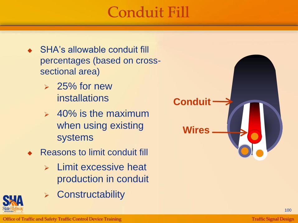
Conduit Fill
SHA‟s allowable conduit fill
percentages (based on cross-
sectional area)
25% for new
installations
40% is the maximum
when using existing
systems
Reasons to limit conduit fill
Limit excessive heat
production in conduit
Constructability
Wires
Conduit
Office of Traffic and Safety Traffic Control Device Training Traffic Signal Design
101
Initial Site Visit
Identify Conceptual Locations of Design
Elements
Poles
Signal Heads
Cabinet(s)
Pedestrian Pushbuttons, Sidewalk Ramps
Crosswalk and Roadway Markings
Signs
Vehicle Detectors
Office of Traffic and Safety Traffic Control Device Training Traffic Signal Design
102
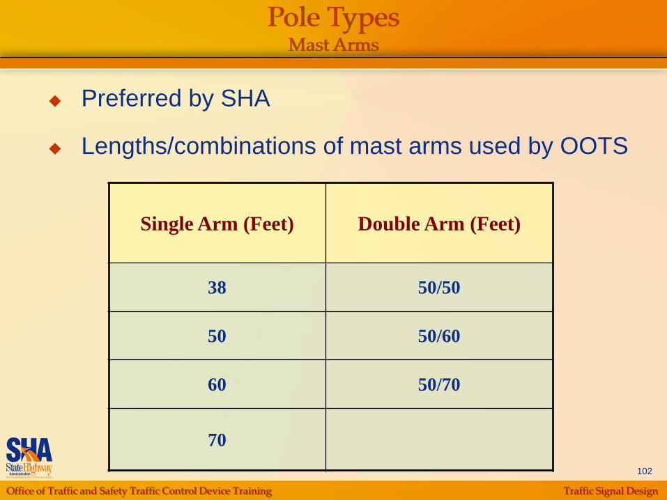
Pole Types Mast Arms
Preferred by SHA
Lengths/combinations of mast arms used by OOTS
Single Arm (Feet) Double Arm (Feet)
38 50/50
50 50/60
60 50/70
70

Office of Traffic and Safety Traffic Control Device Training Traffic Signal Design
103
Pole TypesMast Arms
• 10‟ minimum embedded foundation
• Per the MD-MUTCD, the top of the signal housing located over a roadway shall not be more 25.6 feet above the pavement
Office of Traffic and Safety Traffic Control Device Training Traffic Signal Design
104
Pole TypesSpecial “T” Poles
Special “T” type poles used to avoid
overhead conflicts
Doesn‟t have to be used at all four corner of
the intersection to maintain consistency
unless:
Aesthetic Concerns
Engineering Judgment (i.e. using on more than
one corner)

Office of Traffic and Safety Traffic Control Device Training Traffic Signal Design
105
Pole TypesSpecial “T” Poles
* 15‟ minimum clearance in MUTCD
Office of Traffic and Safety Traffic Control Device Training Traffic Signal Design
106
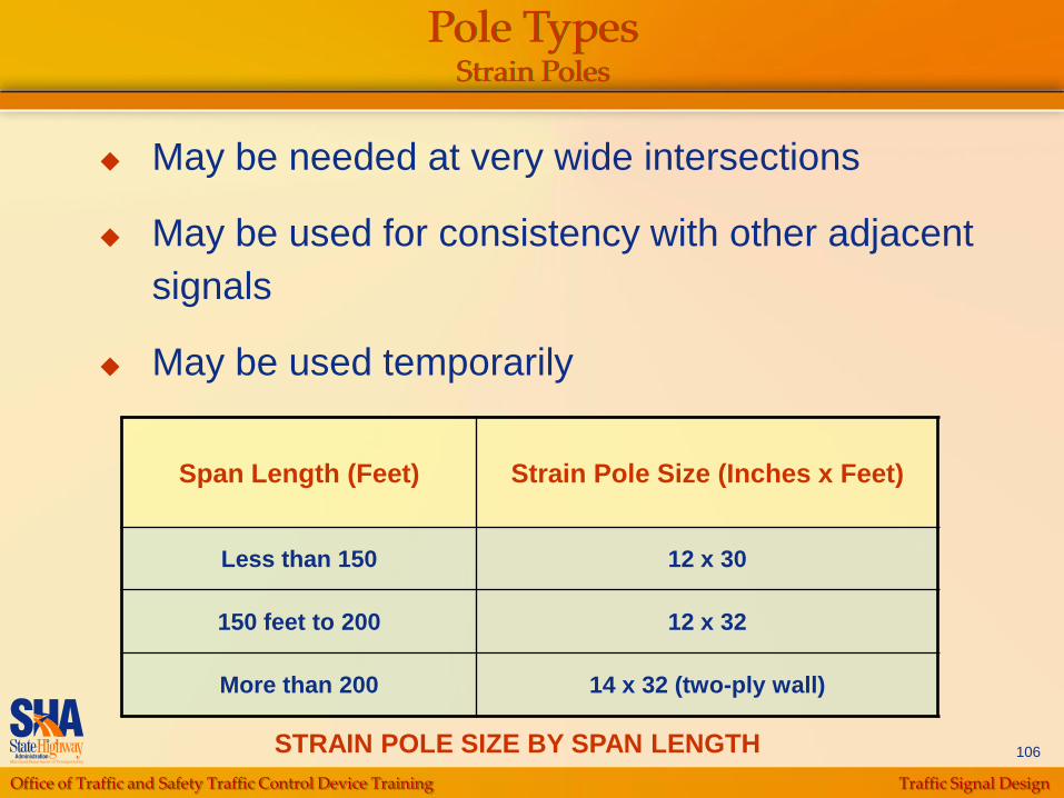
Pole TypesStrain Poles
May be needed at very wide intersections
May be used for consistency with other adjacent
signals
May be used temporarily
Span Length (Feet) Strain Pole Size (Inches x Feet)
Less than 150 12 x 30
150 feet to 200 12 x 32
More than 200 14 x 32 (two-ply wall)
STRAIN POLE SIZE BY SPAN LENGTH
Office of Traffic and Safety Traffic Control Device Training Traffic Signal Design
107
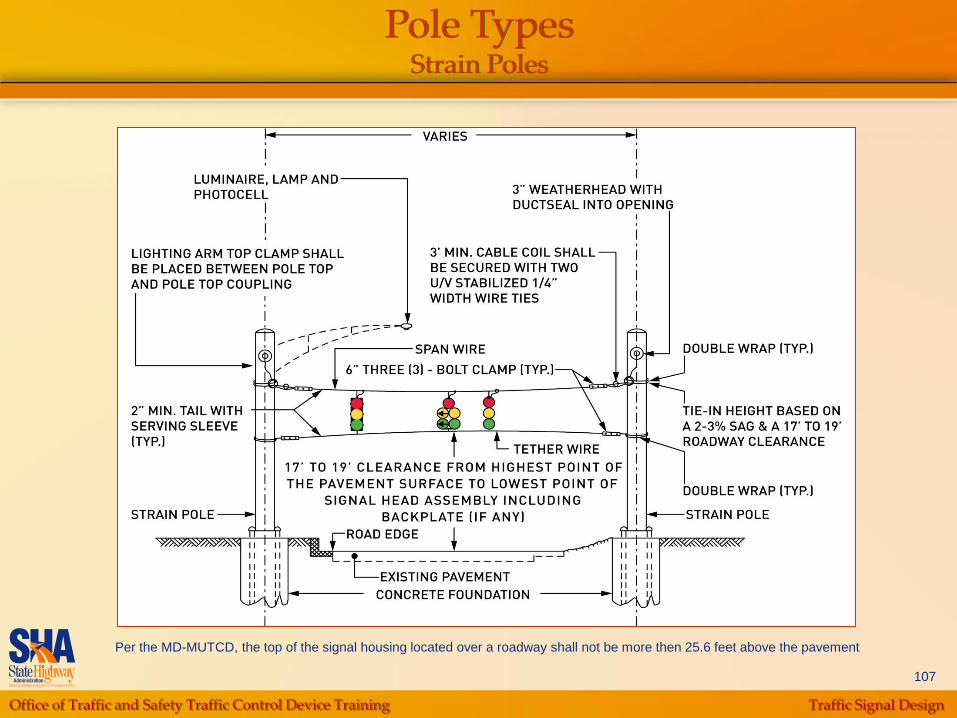
Pole TypesStrain Poles
Per the MD-MUTCD, the top of the signal housing located over a roadway shall not be more then 25.6 feet above the pavement
Office of Traffic and Safety Traffic Control Device Training Traffic Signal Design
108
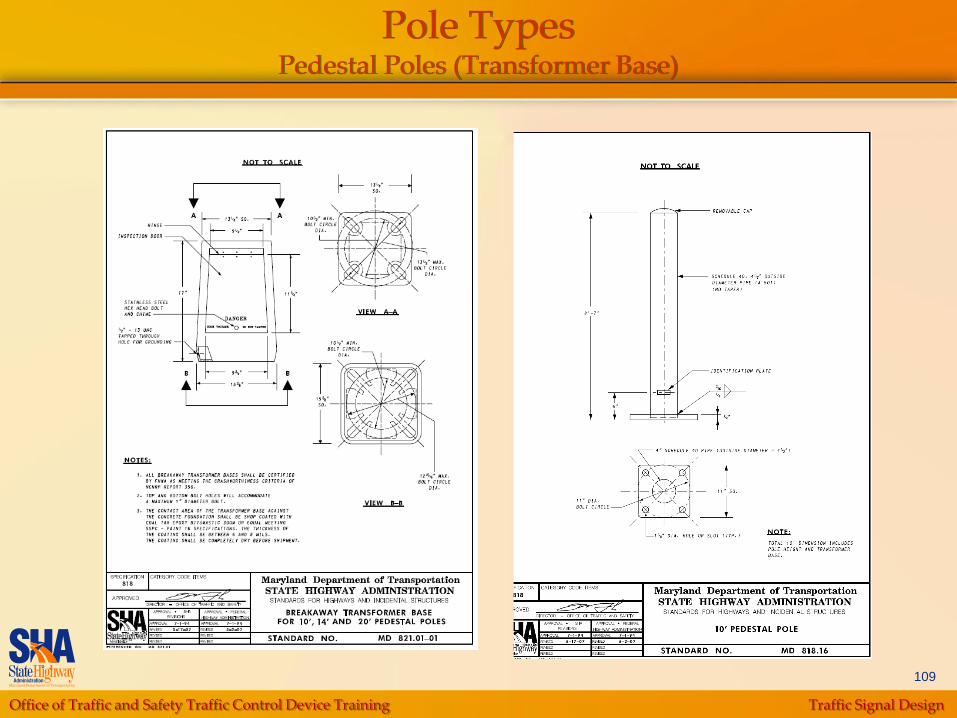
Pole TypesPedestal Poles
Primary usage
Pedestrian signal heads
Left turn signals in median of divided highways
(breakaway)
Push buttons (36” above ground)
In special cases
Utility conflicts
Supplemental signals
Some historic districts
Nominal Pole Heights (including Transformer Base)
10‟, 14‟, or 20‟
Office of Traffic and Safety Traffic Control Device Training Traffic Signal Design
109
Pole TypesPedestal Poles (Transformer Base)

Office of Traffic and Safety Traffic Control Device Training Traffic Signal Design
110
Pole TypesPedestal Poles (Breakaway Coupling)
Office of Traffic and Safety Traffic Control Device Training Traffic Signal Design
111
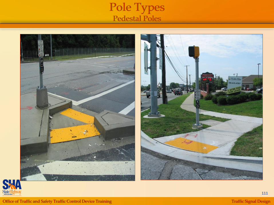
Pole TypesPedestal Poles
Office of Traffic and Safety Traffic Control Device Training Traffic Signal Design
112
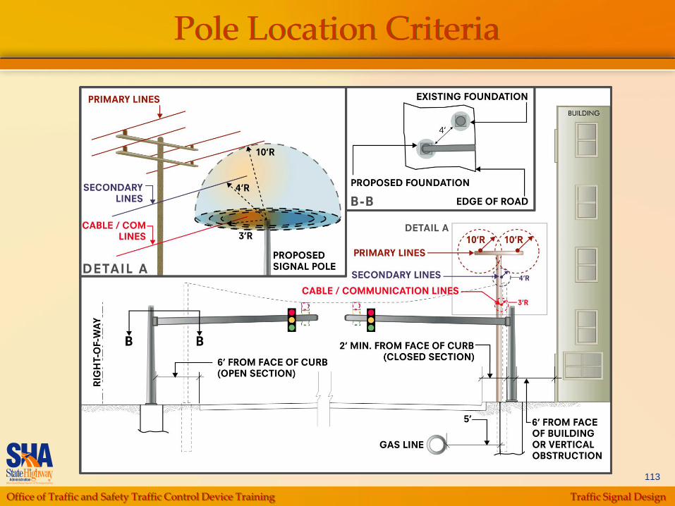
Pole Location Criteria
2‟ minimum from face of curb to face of pole (Closed-
section road-urban environment)
6‟ minimum from edge of road to face of pole (Open-
section road)
6‟ from face of building (or vertical obstruction) to face
of pole
5‟ minimum to gas lines from outside of foundation
4‟ minimum to face of existing pole foundations and
back of w-beam to the face of pole
Within SHA‟s Right-of-Way
Must meet ADA requirements for accessible design
Corner sight distance not impacted
Office of Traffic and Safety Traffic Control Device Training Traffic Signal Design
113
Pole Location Criteria

Office of Traffic and Safety Traffic Control Device Training Traffic Signal Design
114
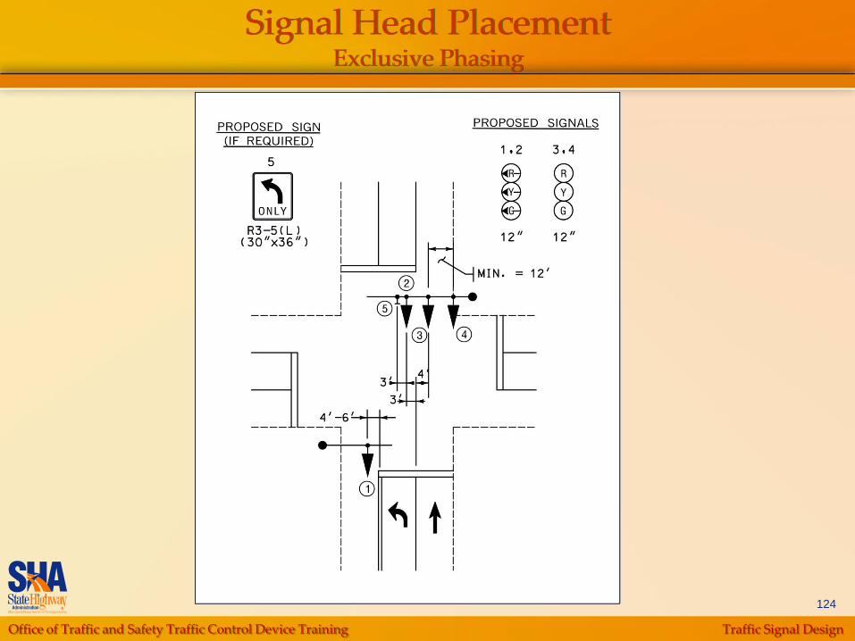
Signal Head Location Assumptions
Number of Heads
Minimum of two heads per movement
Third head is required when
• 85th percentile speed greater than 50 mph and
• Distance to last signal is greater than 3 miles

Office of Traffic and Safety Traffic Control Device Training Traffic Signal Design
115
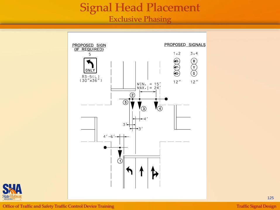
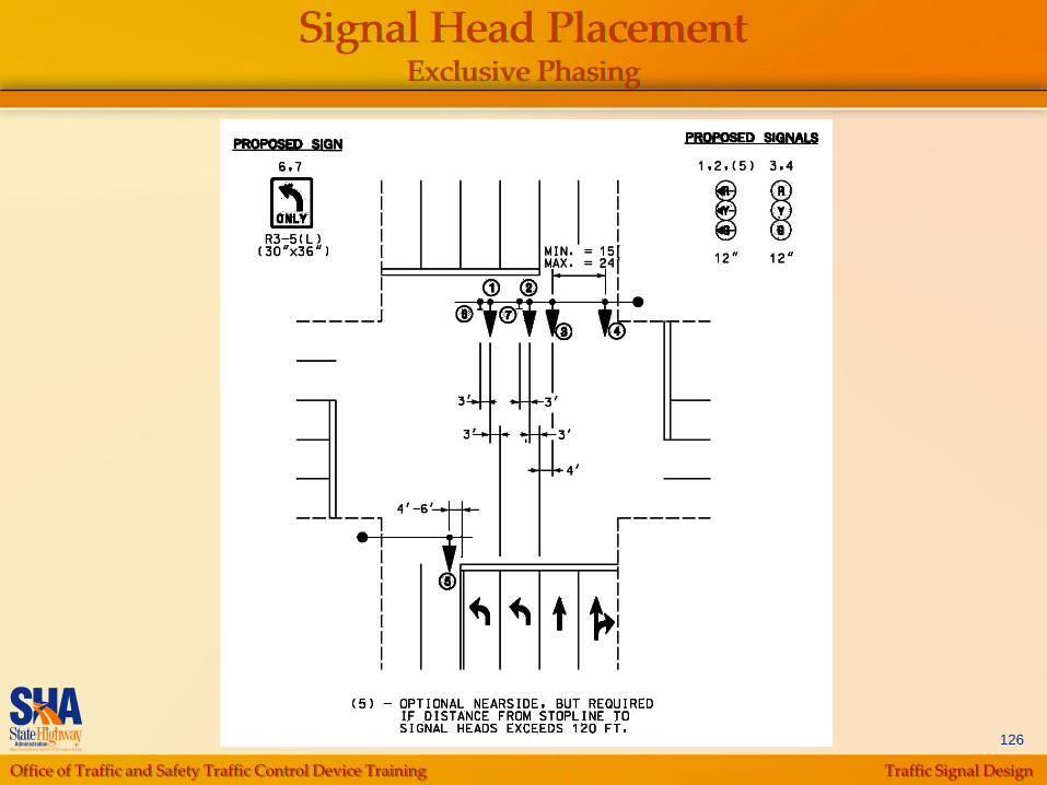
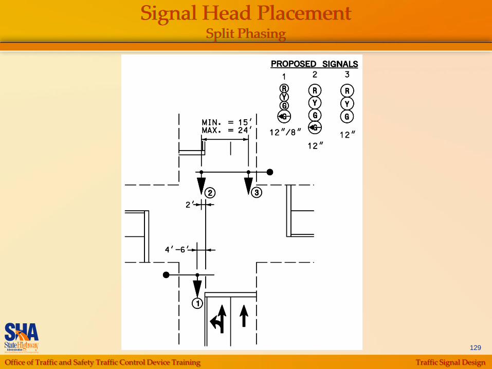
Signal Head Location Assumptions
Location of signal
heads
Minimum distance
from stop line is 40‟
Maximum distance
from stop line is 120‟
with no near-side
signal

Office of Traffic and Safety Traffic Control Device Training Traffic Signal Design
116
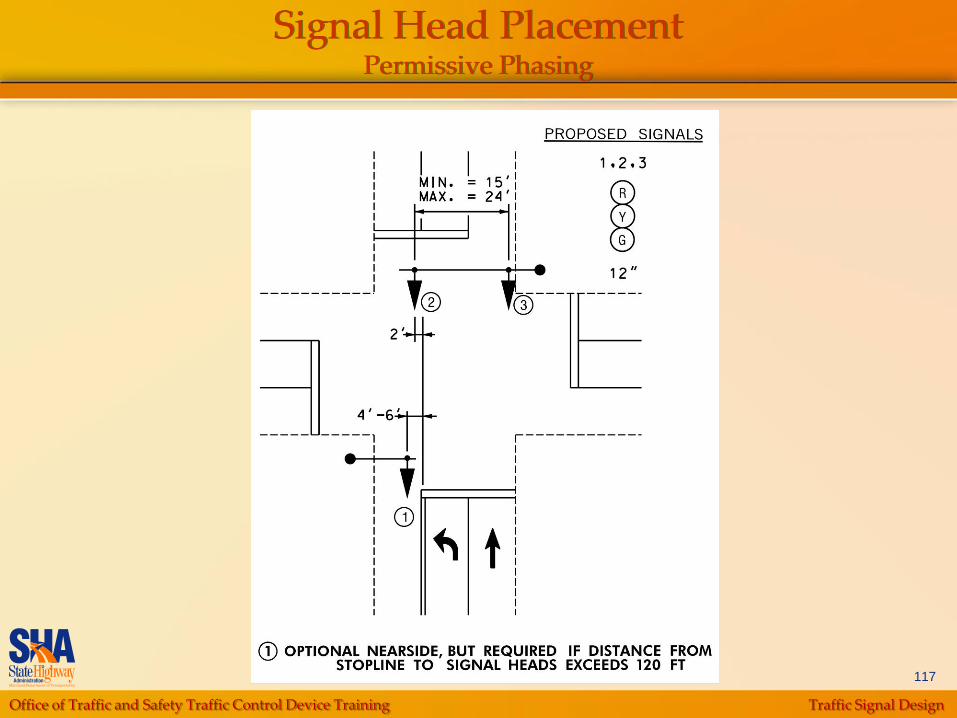
Signal Head PlacementPermissive Phasing
Office of Traffic and Safety Traffic Control Device Training Traffic Signal Design
117
Signal Head PlacementPermissive Phasing
Office of Traffic and Safety Traffic Control Device Training Traffic Signal Design
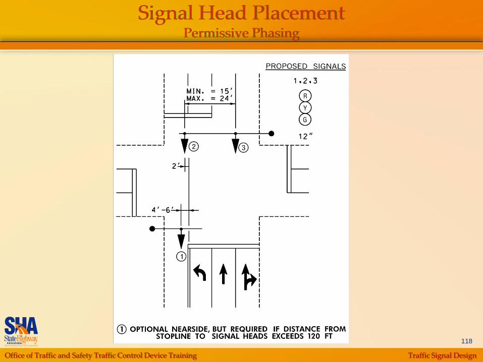
118
Signal Head PlacementPermissive Phasing

Office of Traffic and Safety Traffic Control Device Training Traffic Signal Design
119
Signal Head PlacementPermissive Phasing

Office of Traffic and Safety Traffic Control Device Training Traffic Signal Design
120
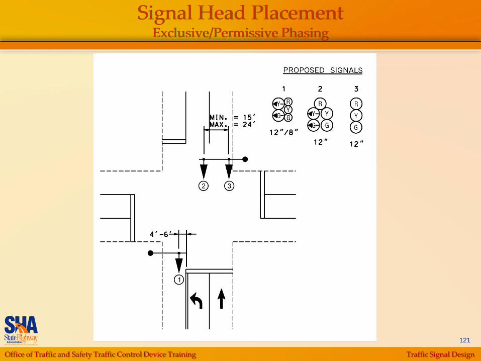
Signal Head PlacementExclusive/Permissive Phasing
Office of Traffic and Safety Traffic Control Device Training Traffic Signal Design
121
Signal Head PlacementExclusive/Permissive Phasing
Office of Traffic and Safety Traffic Control Device Training Traffic Signal Design
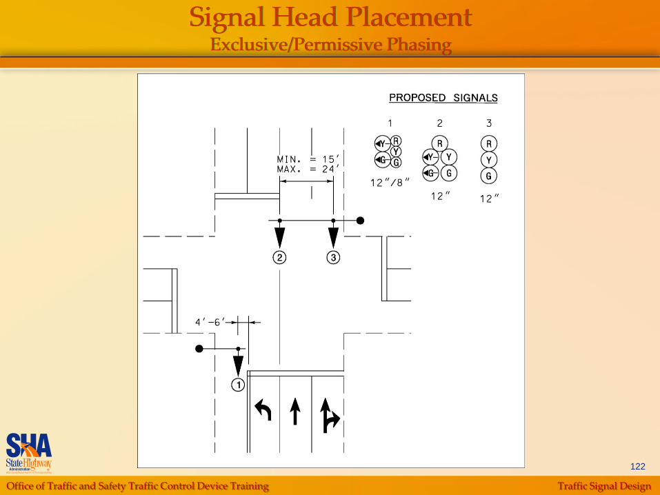
122
Signal Head PlacementExclusive/Permissive Phasing

Office of Traffic and Safety Traffic Control Device Training Traffic Signal Design
123
Signal Head PlacementExclusive/Permissive Phasing
Office of Traffic and Safety Traffic Control Device Training Traffic Signal Design
124
Signal Head PlacementExclusive Phasing
Office of Traffic and Safety Traffic Control Device Training Traffic Signal Design
125
Signal Head PlacementExclusive Phasing
Office of Traffic and Safety Traffic Control Device Training Traffic Signal Design
126
Signal Head PlacementExclusive Phasing

Office of Traffic and Safety Traffic Control Device Training Traffic Signal Design
127
Signal Head PlacementExclusive Phasing

Office of Traffic and Safety Traffic Control Device Training Traffic Signal Design
128
Signal Head PlacementSplit Phasing
Office of Traffic and Safety Traffic Control Device Training Traffic Signal Design
129
Signal Head PlacementSplit Phasing
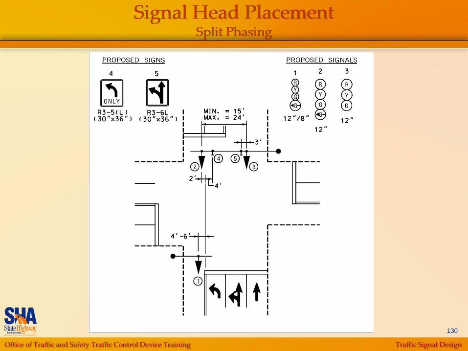
Office of Traffic and Safety Traffic Control Device Training Traffic Signal Design
130
Signal Head PlacementSplit Phasing
Office of Traffic and Safety Traffic Control Device Training Traffic Signal Design
131
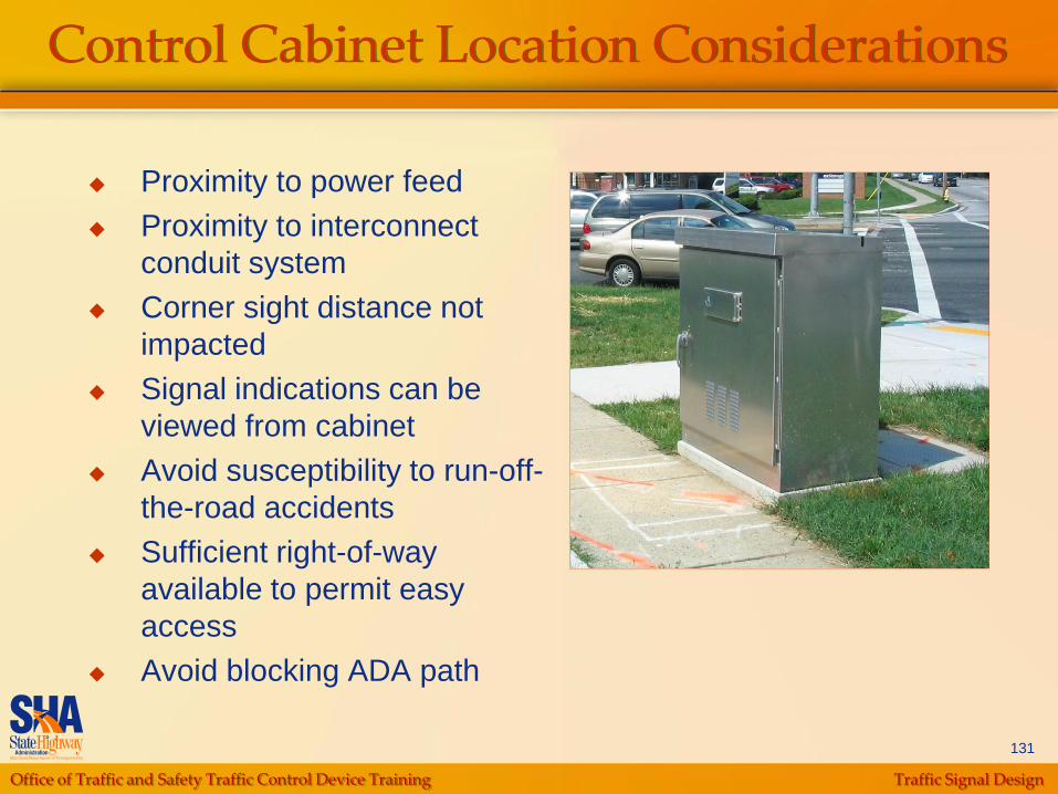
Control Cabinet Location Considerations
Proximity to power feed
Proximity to interconnect
conduit system
Corner sight distance not
impacted
Signal indications can be
viewed from cabinet
Avoid susceptibility to run-off-
the-road accidents
Sufficient right-of-way
available to permit easy
access
Avoid blocking ADA path
Office of Traffic and Safety Traffic Control Device Training Traffic Signal Design
132
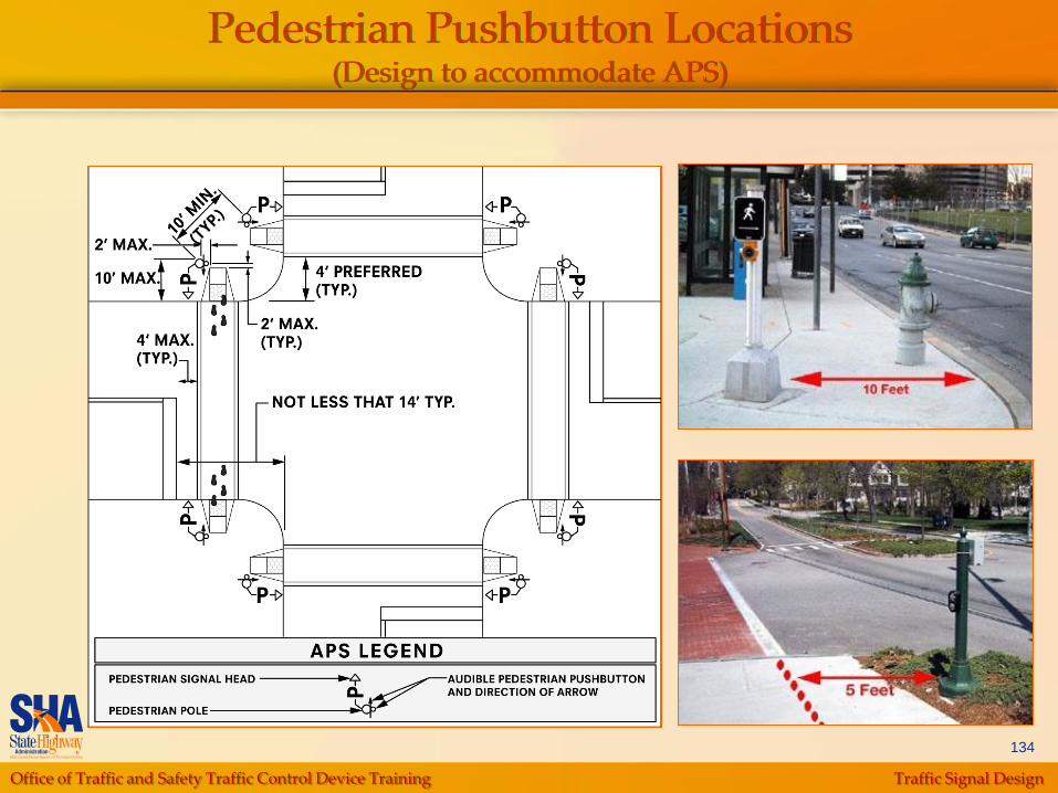
Pedestrian Pushbuttons
Pedestrian Pushbuttons should be located as
follows
Adjacent to a level all-weather surface to provide
access from a wheel chair, and where there is an all-
weather surface, wheel chair accessible route to ramp
(max. 18” reach to pushbutton)
Within 5‟ of crosswalk extended
Within 10‟ of edge of curb, shoulder, or pavement
• But a minimum of 2‟ from face of curb
Provide a minimum of 32” of clearance
Tactile arrows oriented parallel to crosswalk to be used
Office of Traffic and Safety Traffic Control Device Training Traffic Signal Design
133
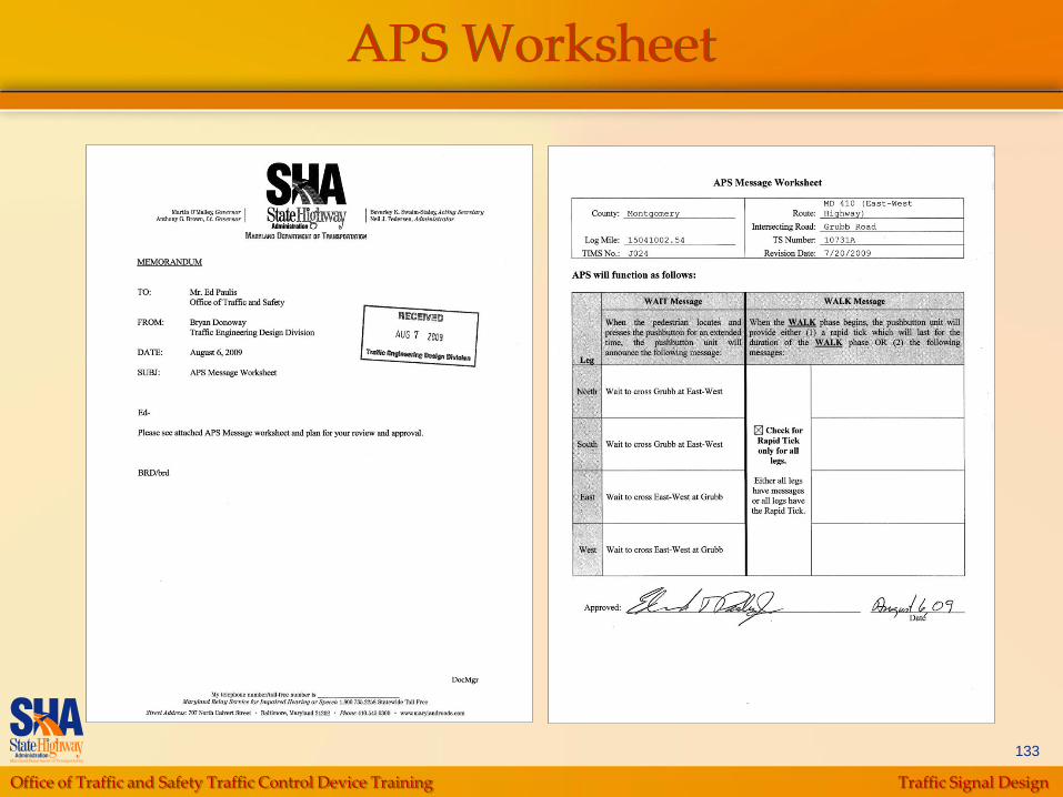
APS Worksheet
Office of Traffic and Safety Traffic Control Device Training Traffic Signal Design
134
Pedestrian Pushbutton Locations(Design to accommodate APS)
Office of Traffic and Safety Traffic Control Device Training Traffic Signal Design
135
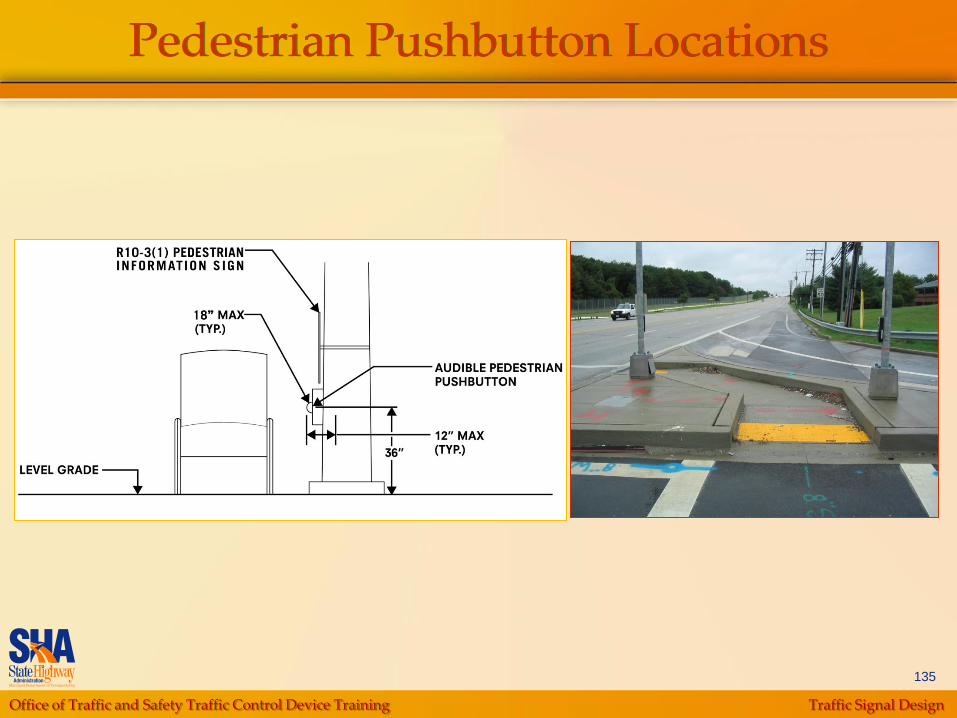
Pedestrian Pushbutton Locations
Office of Traffic and Safety Traffic Control Device Training Traffic Signal Design
136
Pedestrian Pushbutton Locations(Median Pushbutton Issues)
Length of crossing
Signal Phasing
Number of pedestrians
Width of Median
Office of Traffic and Safety Traffic Control Device Training Traffic Signal Design
137
Sidewalks
Minimum width is 60”
Minimum width at isolated pinch points, maximum 24” in length, is 32”
*This does not include the top of curb
Maximum cross-slope is 48:1 (2%)
Anything less must have an approved design waiver

Office of Traffic and Safety Traffic Control Device Training Traffic Signal Design
138
Sidewalk Ramps
Legislation requires that a ramp be provided at pedestrian walkways, which are intersected by curbs. SHA standard ramps are generally compliant with the currently accepted guidelines. However, the standards do not address all potential conditions and constraints. Additional ramp designs are provided within the referenced guidelines.
In cases where none of these standards or designs is appropriate, the designer is required to provide detailed designs for the special ramps.
Office of Traffic and Safety Traffic Control Device Training Traffic Signal Design
139
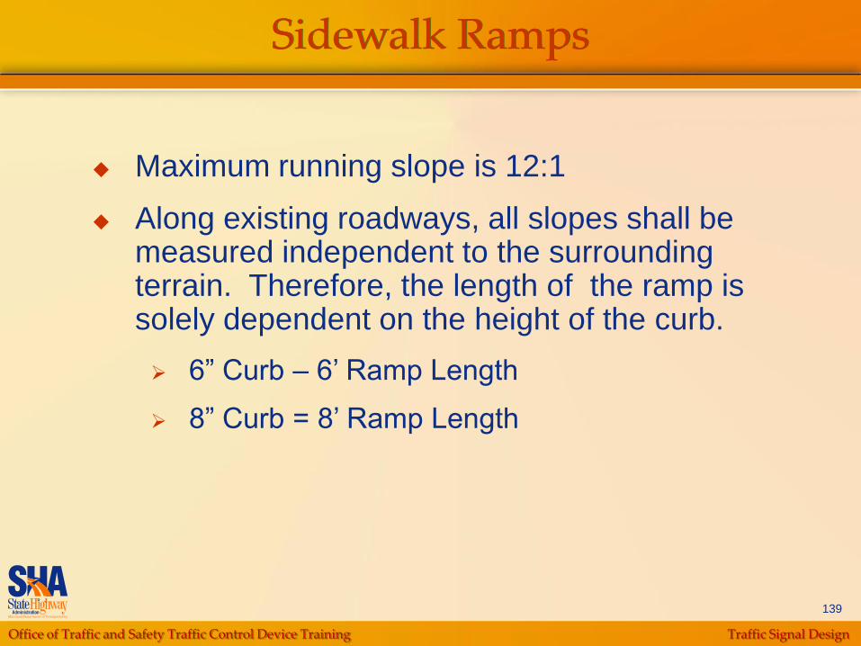
Sidewalk Ramps
Maximum running slope is 12:1
Along existing roadways, all slopes shall be measured independent to the surrounding terrain. Therefore, the length of the ramp is solely dependent on the height of the curb.
6” Curb – 6‟ Ramp Length
8” Curb = 8‟ Ramp Length
Office of Traffic and Safety Traffic Control Device Training Traffic Signal Design
140
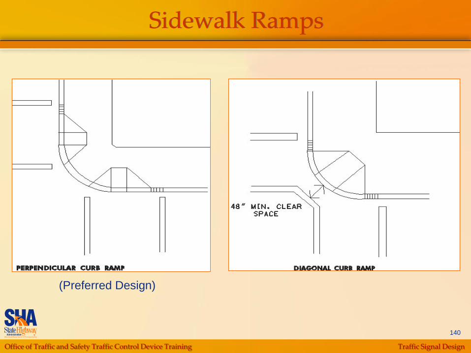
Sidewalk Ramps
(Preferred Design)

Office of Traffic and Safety Traffic Control Device Training Traffic Signal Design
141
Sidewalk Ramps
Flared Design – Typical for Ramp with Wide Sidewalk

Office of Traffic and Safety Traffic Control Device Training Traffic Signal Design
142
Sidewalk Ramps
Tapered Design – Typical for Ramp with Narrow Sidewalk
Office of Traffic and Safety Traffic Control Device Training Traffic Signal Design
143
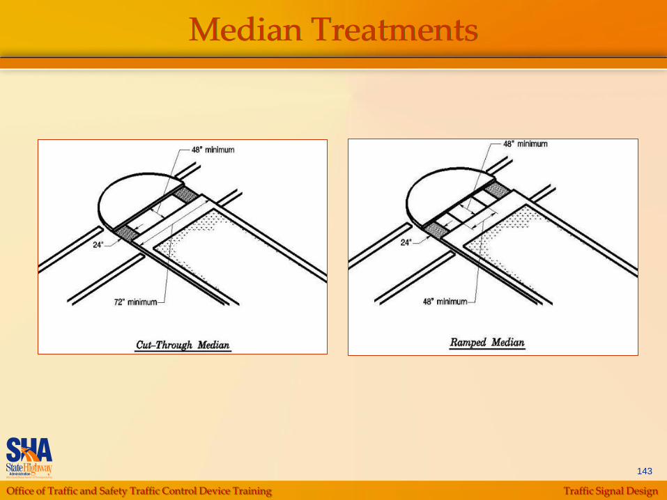
Median Treatments

Office of Traffic and Safety Traffic Control Device Training Traffic Signal Design
144
Sidewalk Ramps
Office of Traffic and Safety Traffic Control Device Training Traffic Signal Design
145
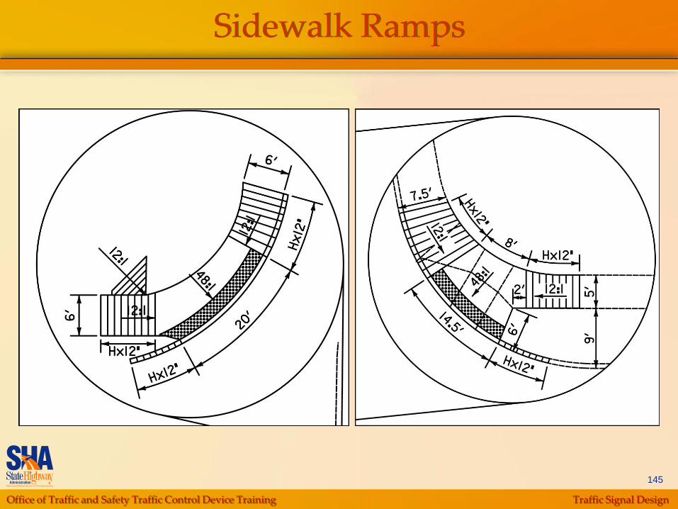
Sidewalk Ramps
Office of Traffic and Safety Traffic Control Device Training Traffic Signal Design
146
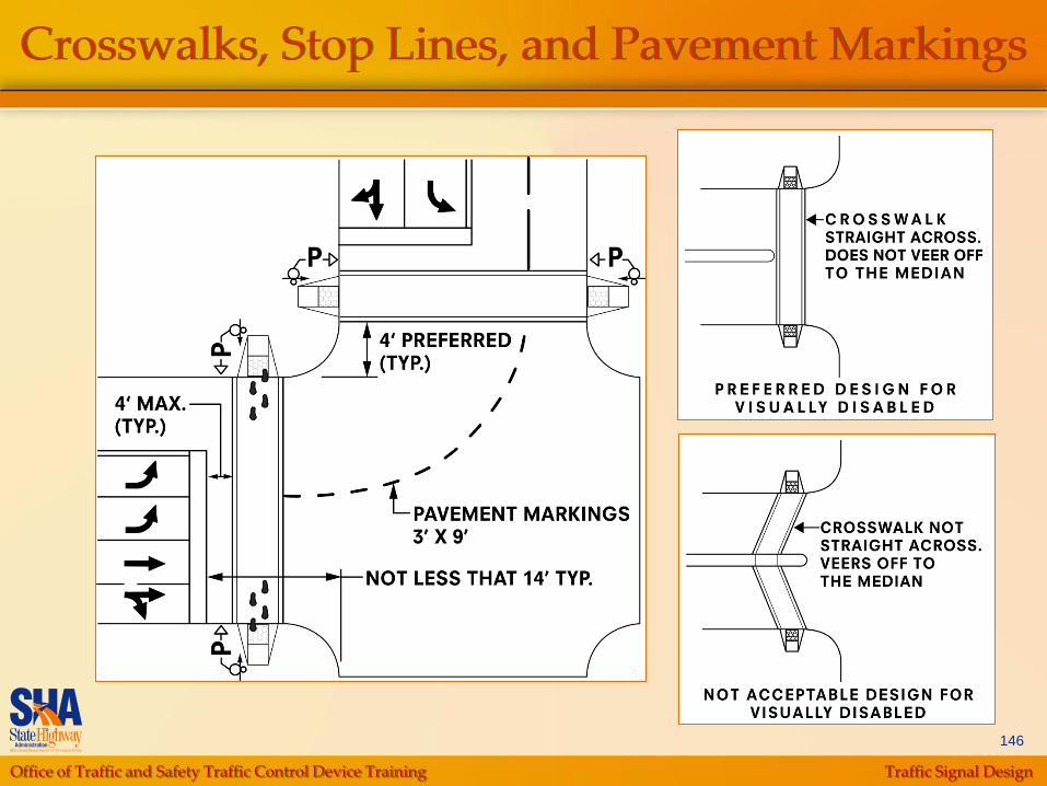
Crosswalks, Stop Lines, and Pavement Markings
Office of Traffic and Safety Traffic Control Device Training Traffic Signal Design
147
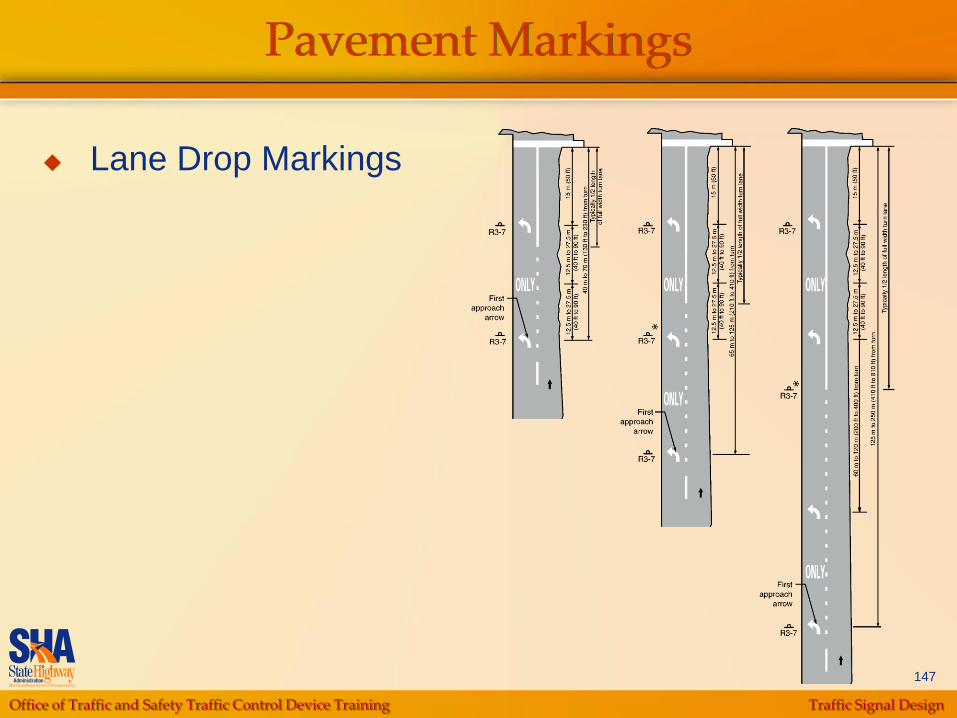
Pavement Markings
Lane Drop Markings
Office of Traffic and Safety Traffic Control Device Training Traffic Signal Design
148
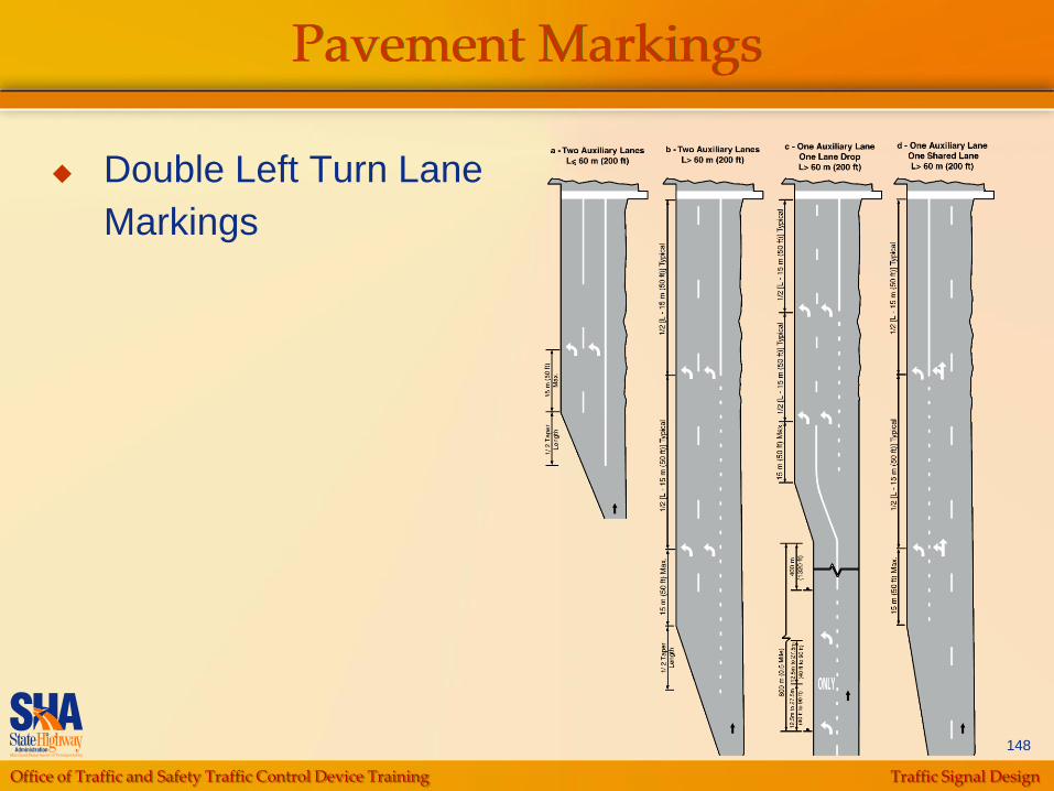
Pavement Markings
Double Left Turn Lane
Markings
Office of Traffic and Safety Traffic Control Device Training Traffic Signal Design
149
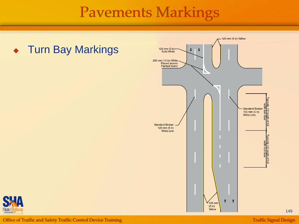
Pavements Markings
Turn Bay Markings

Office of Traffic and Safety Traffic Control Device Training Traffic Signal Design
150
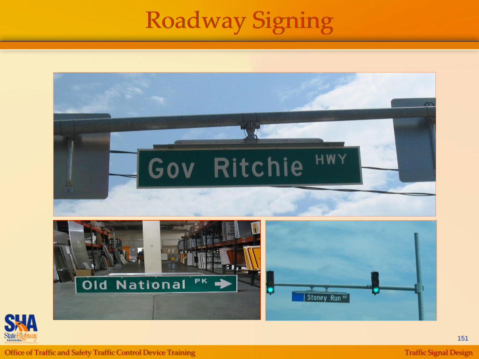
Roadway Signing
Overhead Street Name Signs D-3(1) *See
Standard Sign Book
Installed on all legs of intersection
Mounted near left and far right, dual faced
When different street names on either side
of intersection, left side name on left sign
and right side name on right sign
20” max height
Dual faced if 16” or 20”
Office of Traffic and Safety Traffic Control Device Training Traffic Signal Design
151
Roadway Signing

Office of Traffic and Safety Traffic Control Device Training Traffic Signal Design
152
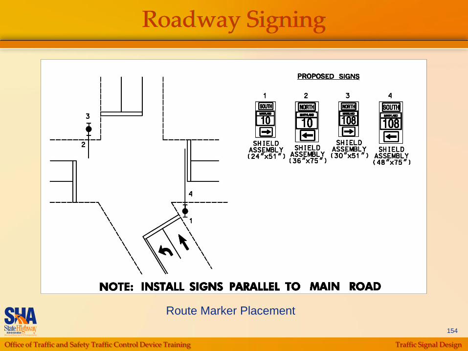
Roadway Signing
Route Marker Assemblies
Facing side street intersections along numbered
routes
Mounted near right and far left, preferably on
signal support
Near side shield assembly – 24” for 2 digits or 30”
for 3 digits x 48” high
Far side assembly – 36” for 2 digits or 48” for 3
digits x 72” high

Office of Traffic and Safety Traffic Control Device Training Traffic Signal Design
153
Roadway Signing
Route Marker Placement
Office of Traffic and Safety Traffic Control Device Training Traffic Signal Design
154
Roadway Signing
Route Marker Placement
Office of Traffic and Safety Traffic Control Device Training Traffic Signal Design
155
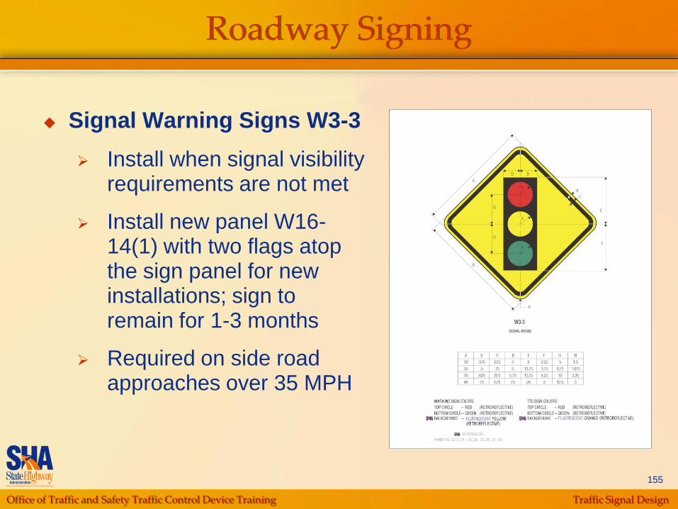
Roadway Signing
Signal Warning Signs W3-3
Install when signal visibility requirements are not met
Install new panel W16-14(1) with two flags atop the sign panel for new installations; sign to remain for 1-3 months
Required on side road approaches over 35 MPH
Office of Traffic and Safety Traffic Control Device Training Traffic Signal Design
156
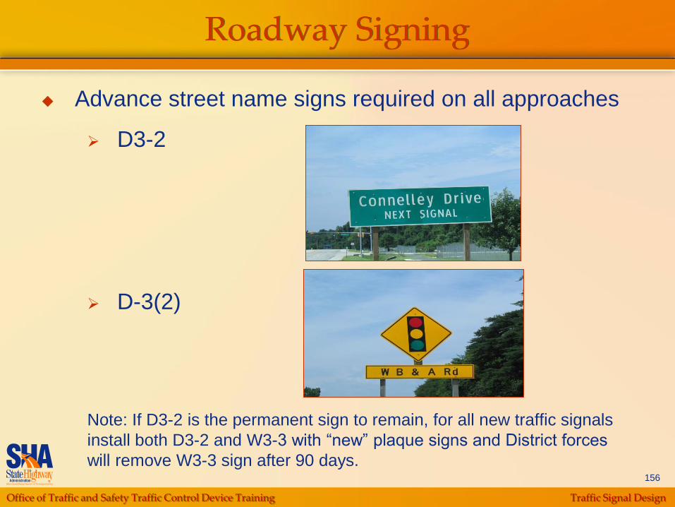
Roadway Signing
Advance street name signs required on all approaches
D3-2
D-3(2)
Note: If D3-2 is the permanent sign to remain, for all new traffic signals
install both D3-2 and W3-3 with “new” plaque signs and District forces
will remove W3-3 sign after 90 days.
Office of Traffic and Safety Traffic Control Device Training Traffic Signal Design
157
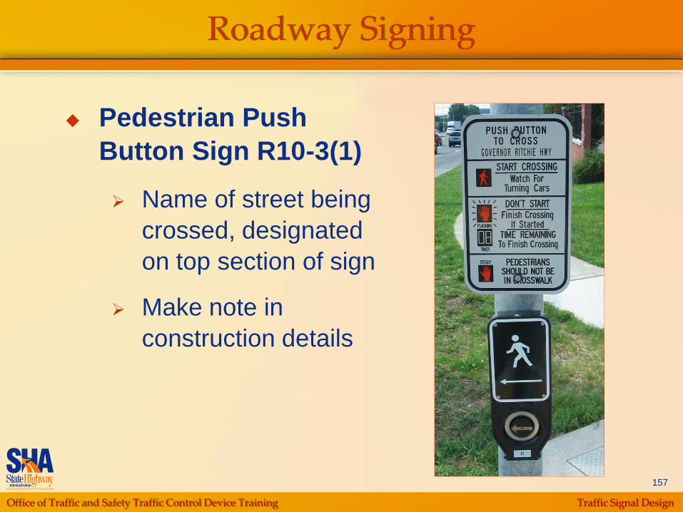
Roadway Signing
Pedestrian Push
Button Sign R10-3(1)
Name of street being
crossed, designated
on top section of sign
Make note in
construction details
Office of Traffic and Safety Traffic Control Device Training Traffic Signal Design
158
Types of Detectors
Non-intrusive (preferred)
Video detection
Non-Invasive Microloop Probe detectors
Intrusive detectors
Inductive loop detectors
Microloop probes
Office of Traffic and Safety Traffic Control Device Training Traffic Signal Design
159
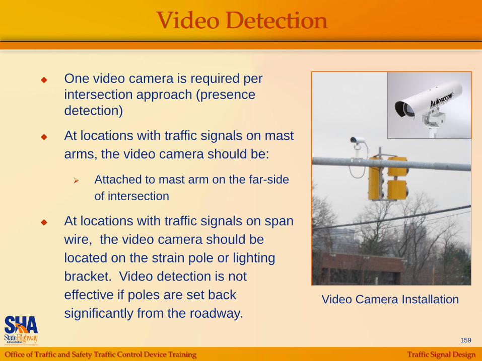
Video Detection
One video camera is required per
intersection approach (presence
detection)
At locations with traffic signals on mast
arms, the video camera should be:
Attached to mast arm on the far-side
of intersection
At locations with traffic signals on span
wire, the video camera should be
located on the strain pole or lighting
bracket. Video detection is not
effective if poles are set back
significantly from the roadway.Video Camera Installation
Office of Traffic and Safety Traffic Control Device Training Traffic Signal Design
160
Video Detection
Installation Issues:
Lighting brackets
Overhead utilities
Presence and passage detection
System detection
Distance from camera to detection zone
Shadow effects
Part-time signals (school signal)
Office of Traffic and Safety Traffic Control Device Training Traffic Signal Design
161
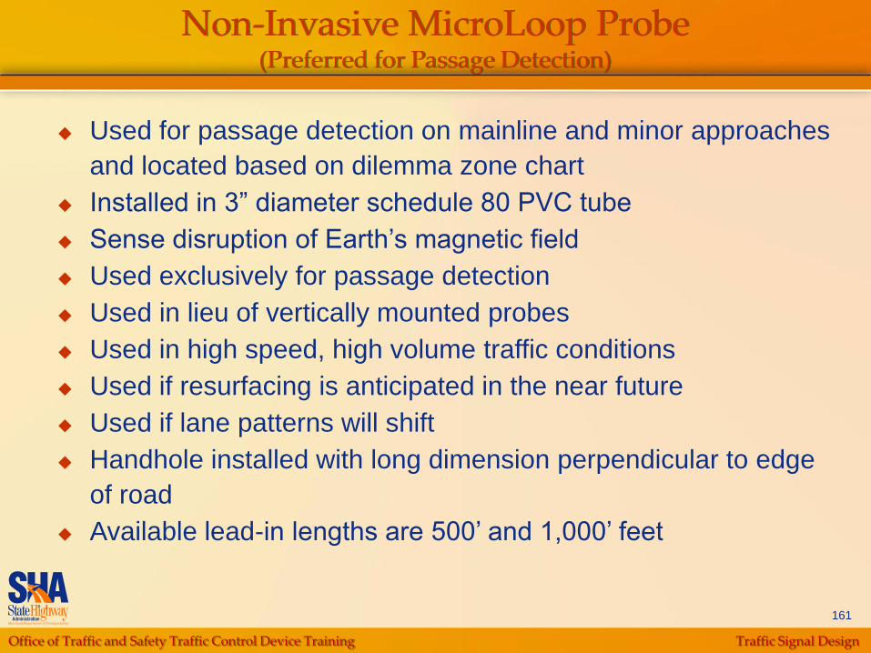
Non-Invasive MicroLoop Probe(Preferred for Passage Detection)
Used for passage detection on mainline and minor approaches
and located based on dilemma zone chart
Installed in 3” diameter schedule 80 PVC tube
Sense disruption of Earth‟s magnetic field
Used exclusively for passage detection
Used in lieu of vertically mounted probes
Used in high speed, high volume traffic conditions
Used if resurfacing is anticipated in the near future
Used if lane patterns will shift
Handhole installed with long dimension perpendicular to edge
of road
Available lead-in lengths are 500‟ and 1,000‟ feet
Office of Traffic and Safety Traffic Control Device Training Traffic Signal Design
162
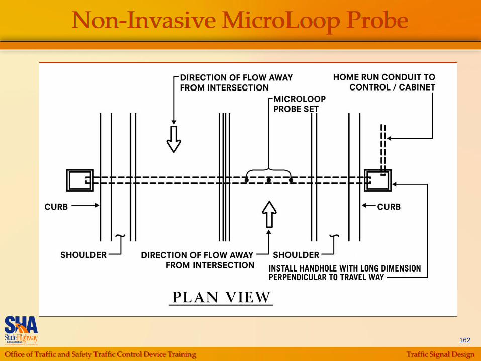
Non-Invasive MicroLoop Probe
Office of Traffic and Safety Traffic Control Device Training Traffic Signal Design
163
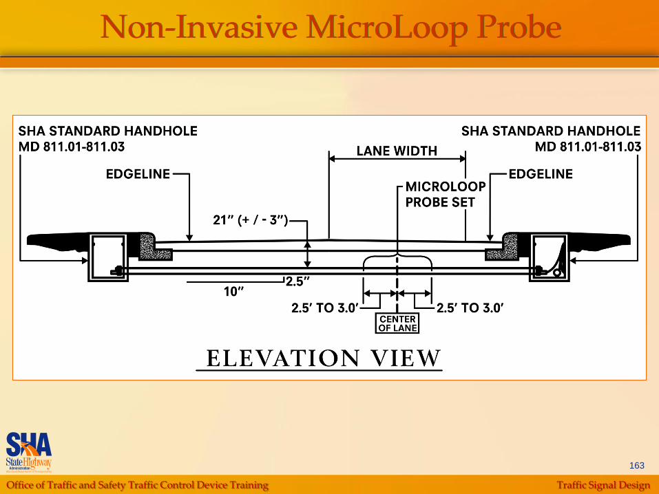
Non-Invasive MicroLoop Probe
Office of Traffic and Safety Traffic Control Device Training Traffic Signal Design
164
Inductive Loop Detectors
Loop detectors create an electrical field at the
surface of the roadway
Connected to controller via two conductor
aluminum shielded cables; creates a continuous
run of wire from controller to loop detector and
back again
Need to avoid surface features (manholes, gas
valve, etc.)
Avoid installing in deteriorated pavement
(susceptible to failure)
Avoid long lead-in cables (susceptible to failure)
Office of Traffic and Safety Traffic Control Device Training Traffic Signal Design
165
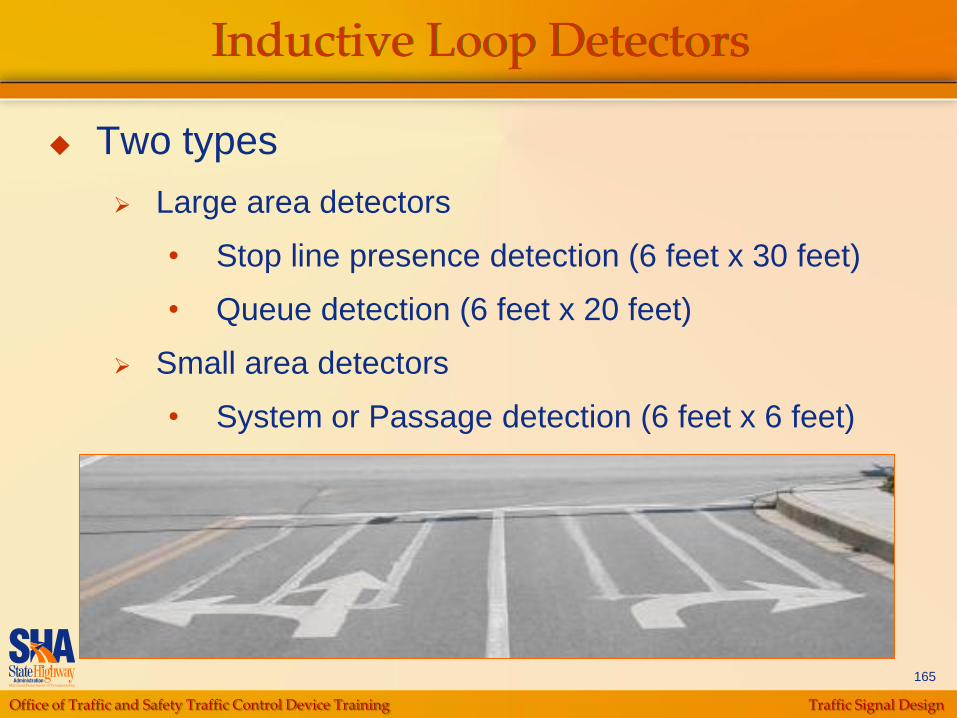
Inductive Loop Detectors
Two types
Large area detectors
• Stop line presence detection (6 feet x 30 feet)
• Queue detection (6 feet x 20 feet)
Small area detectors
• System or Passage detection (6 feet x 6 feet)
Office of Traffic and Safety Traffic Control Device Training Traffic Signal Design
166
Large Area Detectors
Located 12” behind the stop line
Quadruple design
3 longitudinal sawcuts
Figure 8 wrap pattern
• 3-6-3 in asphalt
• 2-4-2 in concrete
Used for presence detection on minor approaches or ramps and mainline approaches with left or right turn phasing
Labeled „Delay Output‟ when used for exclusive right turn lanes or left turn lanes with exclusive/permissive phasing
Office of Traffic and Safety Traffic Control Device Training Traffic Signal Design
167
Small Area Detectors
Used for passage detection on mainline and minor
approaches and located based on dilemma zone
chart
Used for system detection on mainline and located
beyond intersection
Four turn wrap pattern
Office of Traffic and Safety Traffic Control Device Training Traffic Signal Design
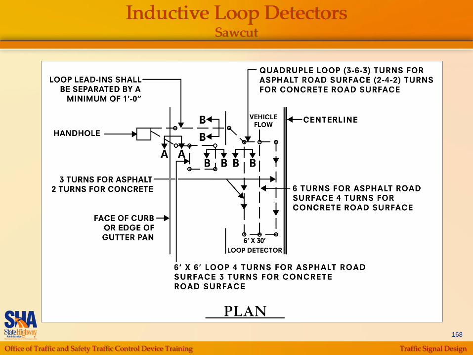
168
Inductive Loop DetectorsSawcut

Office of Traffic and Safety Traffic Control Device Training Traffic Signal Design
169
Microloop Probes
Sense disruption of Earth‟s magnetic field
Used exclusively for passage detection on mainline and
minor approaches; located based on dilemma zone chart
Grouped in sets of 3, which are installed in 1½” diameter
holes drilled vertically in the road surface
Not to be used in the following situations:
In concrete pavement or tunnels
Around power lines or rail lines
On bridge decks
Lead-ins run in a 3/8” inch wide slot from probe set to
controller (available lead-in lengths are 500‟ and
1,000‟)
Office of Traffic and Safety Traffic Control Device Training Traffic Signal Design
170
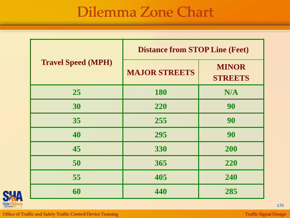
Dilemma Zone Chart
Travel Speed (MPH)
Distance from STOP Line (Feet)
MAJOR STREETSMINOR
STREETS
25 180 N/A
30 220 90
35 255 90
40 295 90
45 330 200
50 365 220
55 405 240
60 440 285
Office of Traffic and Safety Traffic Control Device Training Traffic Signal Design
171
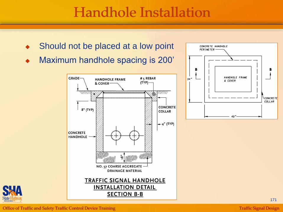
Handhole Installation
Should not be placed at a low point
Maximum handhole spacing is 200‟

Office of Traffic and Safety Traffic Control Device Training Traffic Signal Design
172
Conduit Installation Methods
Trenched - in grass or dirt
Bored (directional-drilled) - under pavement
Must test pit if crossing utilities
Slotted - in pavement surfaces where it
cannot be bored (utilities or constructability)
Office of Traffic and Safety Traffic Control Device Training Traffic Signal Design
173
Conduit System
Schedule 80 PVC conduits are used for most runs
between handholes, controller and pole bases
2 or 3 inch minimum conduit trenched
3 or 4 inch minimum conduit bored/slotted
Detector sleeves are used from handhole to edge of
travel lanes
1 inch liquid-tight flexible non-metallic conduit (runs
less than 6‟)
1 inch galvanized electrical conduit (runs greater
than 6‟)
Office of Traffic and Safety Traffic Control Device Training Traffic Signal Design
174
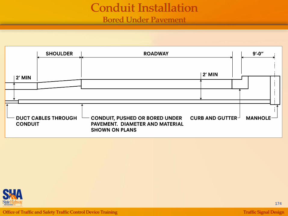
Conduit InstallationBored Under Pavement
Office of Traffic and Safety Traffic Control Device Training Traffic Signal Design
175
Conduit InstallationConsiderations
Underground utilities (need to test pit)
Boring requires 20‟ of clearance for boring
machine
Slope – will hand digging be required?
Sidewalk – need to repair
Location of driveways
Has roadway been recently resurfaced or
scheduled to be?

Office of Traffic and Safety Traffic Control Device Training Traffic Signal Design
176
Preemption Equipment
Identify Preemption Equipment locations for
Firehouses, Train Crossings, Emergency Vehicles,
Buses
Push Button
Opticom Receivers
• Optimal line of sight is 1,500‟
• Consider measures to clear queues for emergency
vehicles
Coordinate method of actuation with fire house chief
Hard-wire signal if within 800‟ of intersection
Office of Traffic and Safety Traffic Control Device Training Traffic Signal Design
177
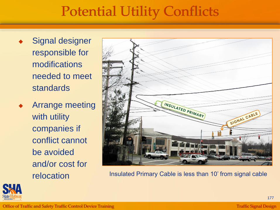
Potential Utility Conflicts
Insulated Primary Cable is less than 10‟ from signal cable
Signal designer
responsible for
modifications
needed to meet
standards
Arrange meeting
with utility
companies if
conflict cannot
be avoided
and/or cost for
relocation
Office of Traffic and Safety Traffic Control Device Training Traffic Signal Design
178
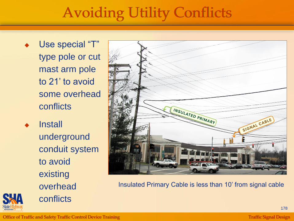
Avoiding Utility Conflicts
Insulated Primary Cable is less than 10‟ from signal cable
Use special “T”
type pole or cut
mast arm pole
to 21‟ to avoid
some overhead
conflicts
Install
underground
conduit system
to avoid
existing
overhead
conflicts
Office of Traffic and Safety Traffic Control Device Training Traffic Signal Design
179
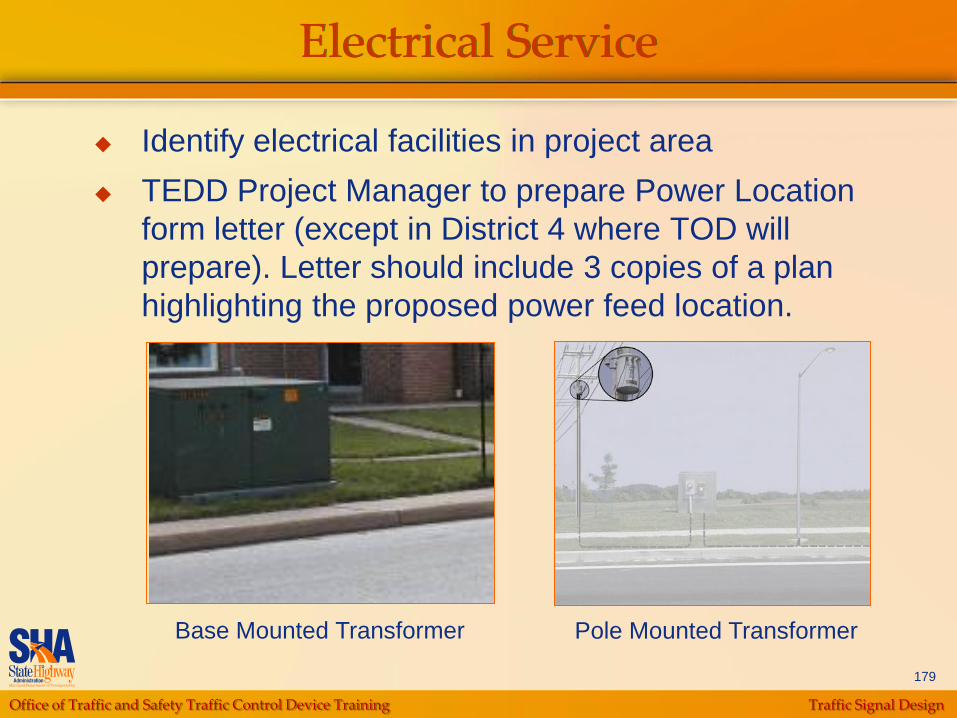
Electrical Service
Identify electrical facilities in project area
TEDD Project Manager to prepare Power Location
form letter (except in District 4 where TOD will
prepare). Letter should include 3 copies of a plan
highlighting the proposed power feed location.
Base Mounted Transformer Pole Mounted Transformer
Office of Traffic and Safety Traffic Control Device Training Traffic Signal Design
180
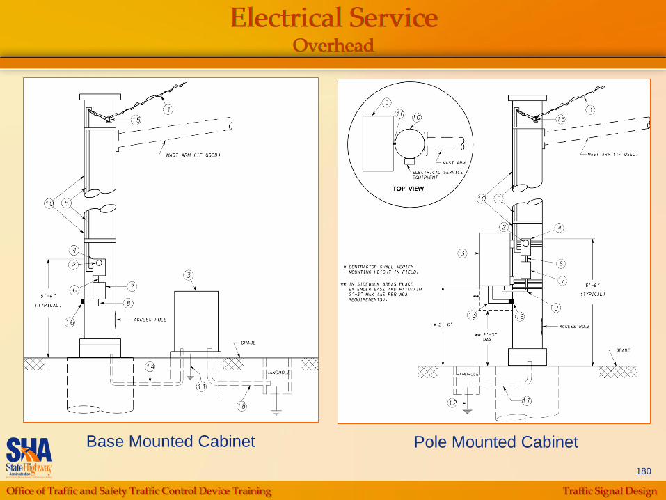
Electrical ServiceOverhead
Base Mounted Cabinet Pole Mounted Cabinet
Office of Traffic and Safety Traffic Control Device Training Traffic Signal Design
181
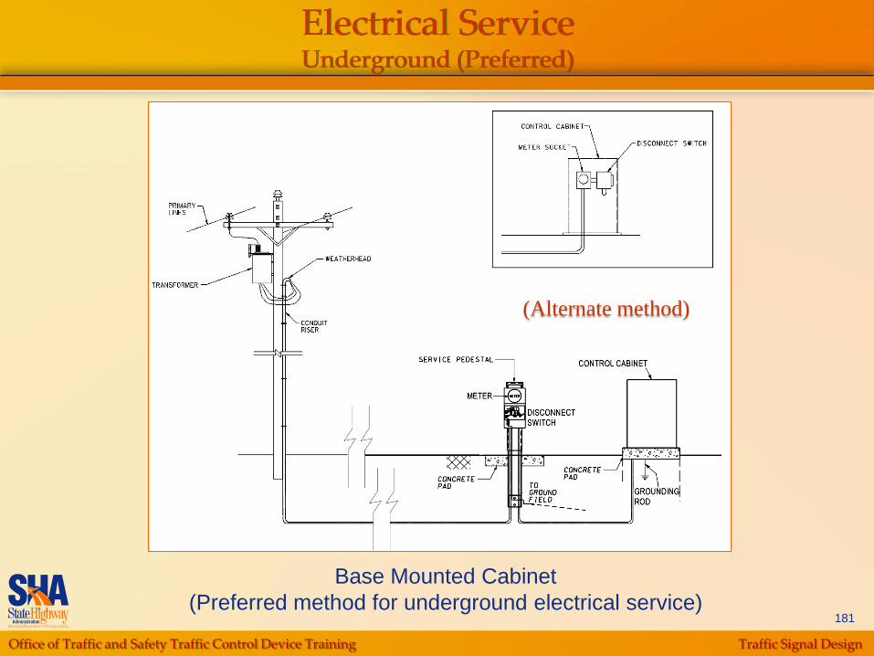
Electrical ServiceUnderground (Preferred)
Base Mounted Cabinet
(Preferred method for underground electrical service)
(Alternate method)
Office of Traffic and Safety Traffic Control Device Training Traffic Signal Design
182
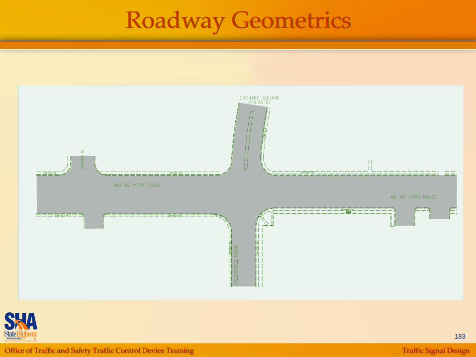
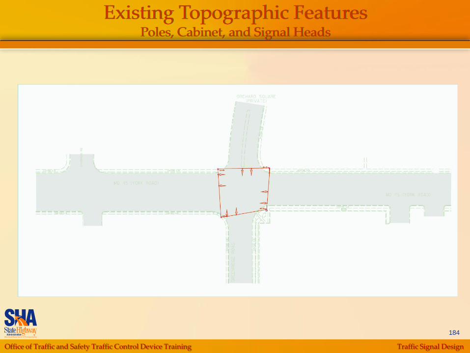
Base Map
From available plans/plats, site visit data
(tape and wheel survey) or by professional
surveyor, develop the base map, showing:
Roadway Geometrics
Existing Topographic Features
• Poles, Signal Heads and Cabinet (Rebuild
Projects)
• Sign Structures, Crosswalks and Roadway
Markings
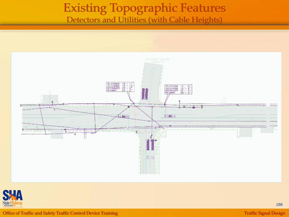
• Detectors and Utilities, including Cable Heights
Right-of-Way Lines
Office of Traffic and Safety Traffic Control Device Training Traffic Signal Design
183
Roadway Geometrics
Office of Traffic and Safety Traffic Control Device Training Traffic Signal Design
184
Existing Topographic FeaturesPoles, Cabinet, and Signal Heads

Office of Traffic and Safety Traffic Control Device Training Traffic Signal Design
185
Existing Topographic FeaturesSigns, Crosswalk, and Roadway Markings
Office of Traffic and Safety Traffic Control Device Training Traffic Signal Design
186
Existing Topographic FeaturesDetectors and Utilities (with Cable Heights)

Office of Traffic and Safety Traffic Control Device Training Traffic Signal Design
187
Right-of-Way
Office of Traffic and Safety Traffic Control Device Training Traffic Signal Design
188
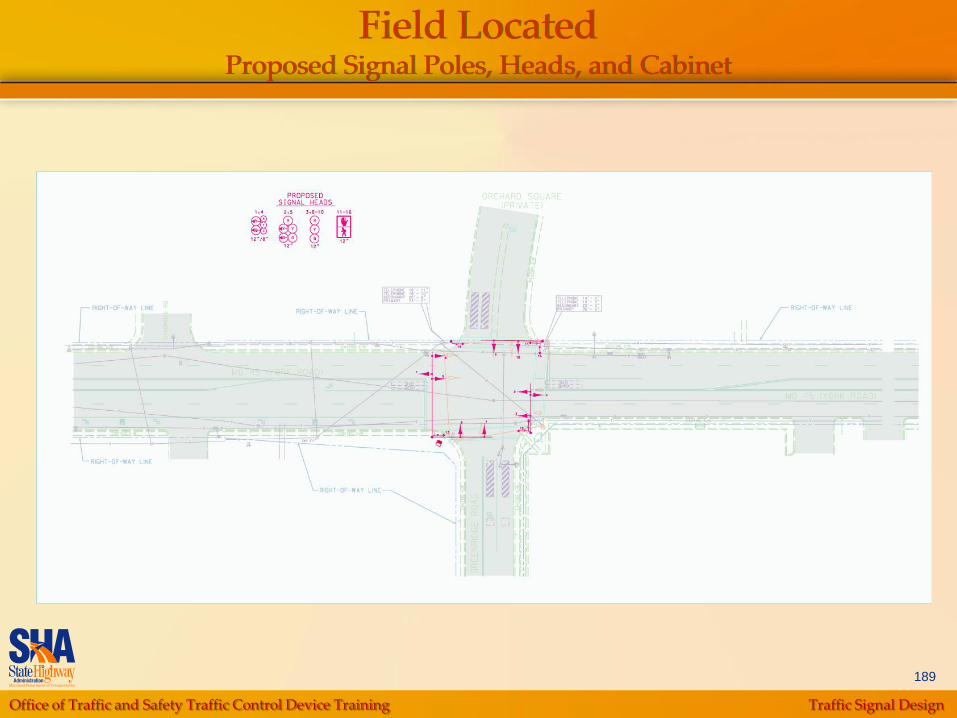
Preliminary Investigation (PI) Plan Development
Add field-located, proposed equipment to the
Base Map:
Signal Poles, Head Locations and Cabinet
Sign Locations and Numbering
Pedestrian Pushbuttons, Sidewalk Ramps,
Crosswalks and Roadway Markings
Vehicle Detectors
Lighting (Not applicable at Sample Location)
Pre-emption Equipment (Not applicable at
Sample Location)
HIB‟s (Not applicable at Sample Location)
Office of Traffic and Safety Traffic Control Device Training Traffic Signal Design
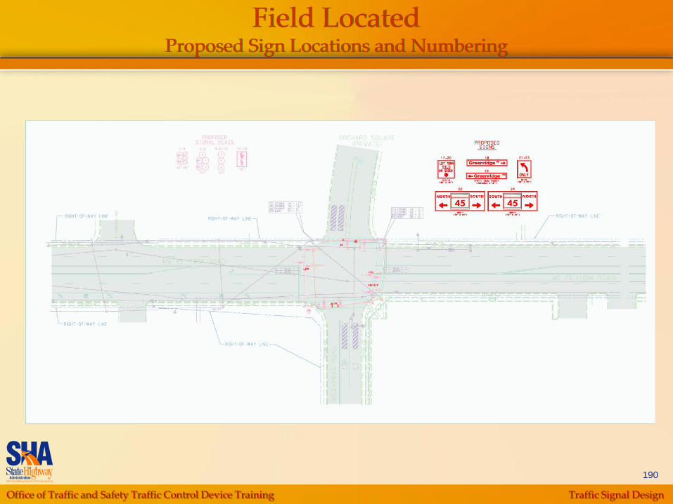
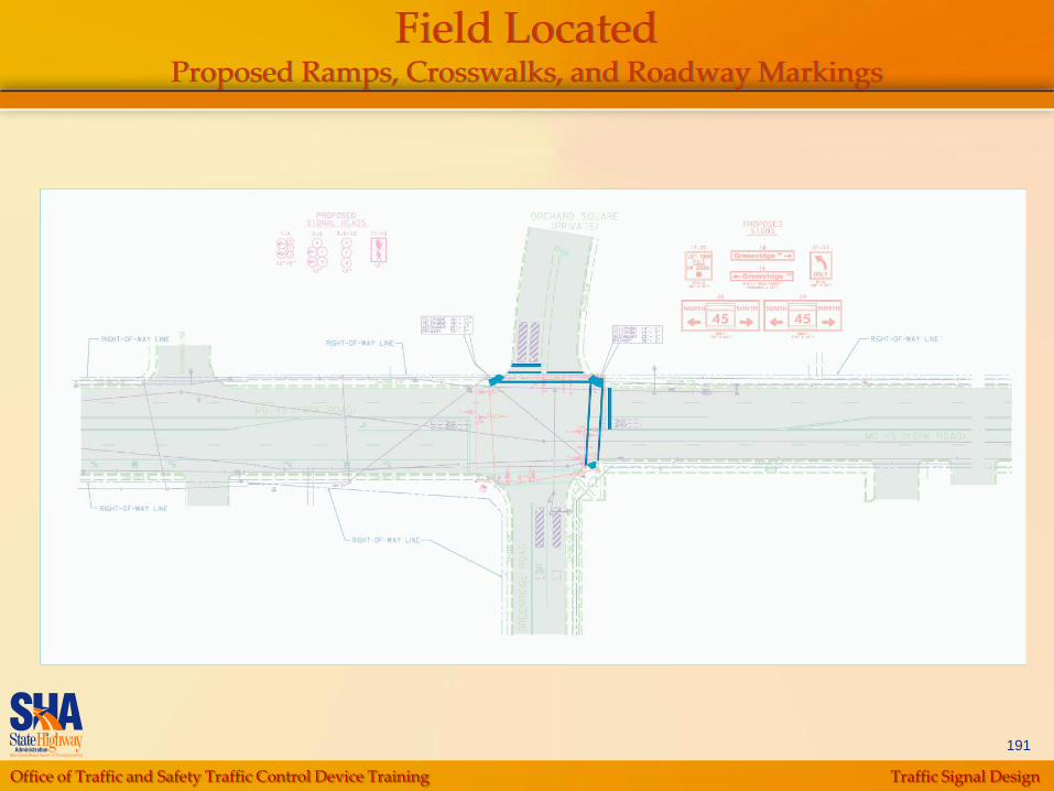
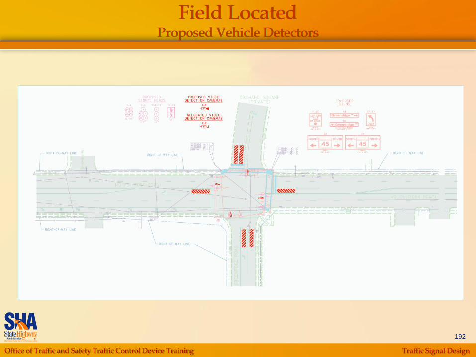
189
Field LocatedProposed Signal Poles, Heads, and Cabinet
Office of Traffic and Safety Traffic Control Device Training Traffic Signal Design
190
Field LocatedProposed Sign Locations and Numbering
Office of Traffic and Safety Traffic Control Device Training Traffic Signal Design
191
Field LocatedProposed Ramps, Crosswalks, and Roadway Markings
Office of Traffic and Safety Traffic Control Device Training Traffic Signal Design
192
Field LocatedProposed Vehicle Detectors

Office of Traffic and Safety Traffic Control Device Training Traffic Signal Design
193
Title Block with Intersection Name
Office of Traffic and Safety Traffic Control Device Training Traffic Signal Design
194
North Arrow Note
Typically located in the upper left corner of plan
Typically oriented up (i.e., above the horizontal
axis)
Note assumed direction of major street, either
EW or NS (basis for numbering signal
indications)
Office of Traffic and Safety Traffic Control Device Training Traffic Signal Design
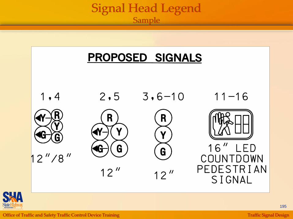
195
Signal Head LegendSample

Office of Traffic and Safety Traffic Control Device Training Traffic Signal Design
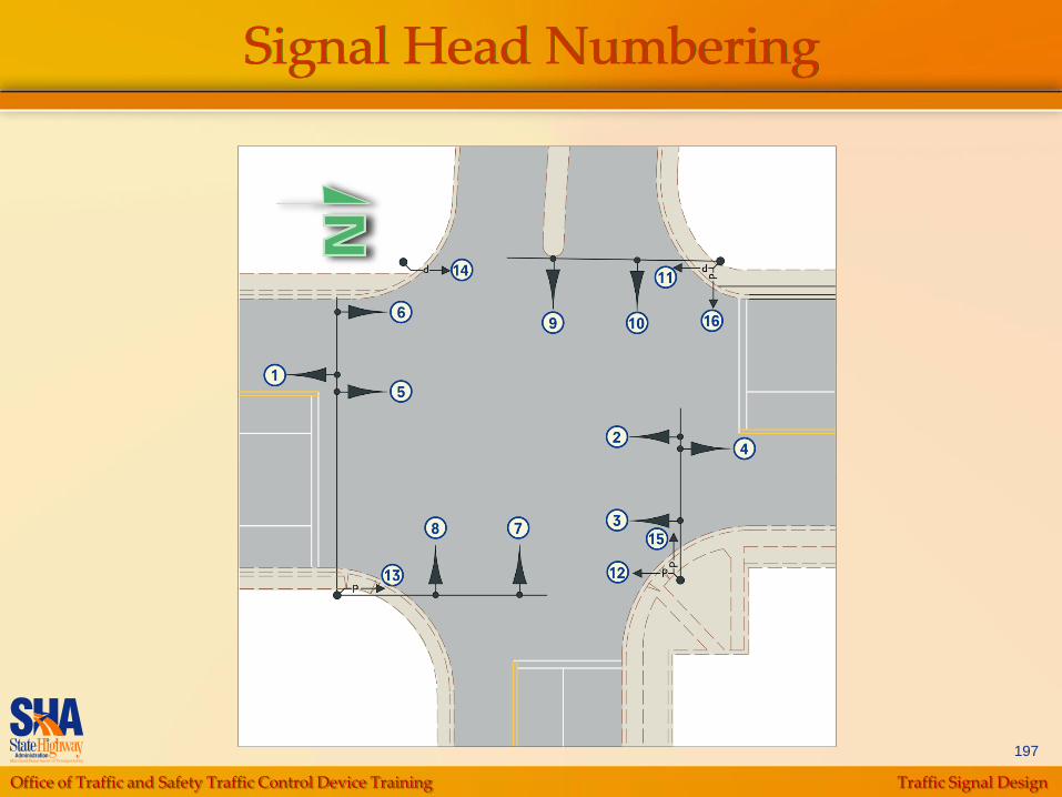
196
Signal Head Numbering
Numbered on the plan uniformly using the following
criteria:
Mainline signals numbered first
• If Mainline runs in a north-south direction, signal heads facing
northbound traffic are numbered first
• If Mainline runs in an east-west direction, signal heads facing
eastbound traffic are numbered first
Minor roads are numbered next using the same rules as above
Signal heads are numbered in increasing order from left to right
Near-side heads are numbered first on each approach
Pedestrian heads and signs are numbered last using the same rules
as above
Office of Traffic and Safety Traffic Control Device Training Traffic Signal Design
197
Signal Head Numbering
Office of Traffic and Safety Traffic Control Device Training Traffic Signal Design
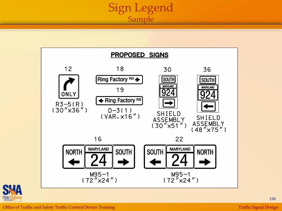
198
Sign LegendSample

Office of Traffic and Safety Traffic Control Device Training Traffic Signal Design
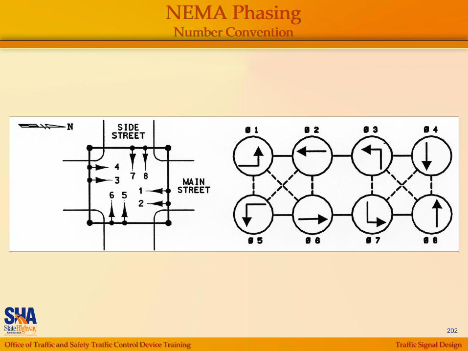
199
NEMA Phasing Diagram
Typically located in upper right hand corner of
the plan
Follow NEMA Phasing Number Convention
Major Street
• Left turn signals (Phases 1 and 5)
• Thru signals (Phases 2 and 6)
Minor Street
• Left turn signals (Phases 3 and 7)
• Thru signals (Phases 4 and 8)

Office of Traffic and Safety Traffic Control Device Training Traffic Signal Design
200
NEMA Phasing Number Convention
Main Street direction based on North Arrow
For split phasing, use Phases 3 and 4 only
for the side streets
At a T intersection, side street is Phase 4

Office of Traffic and Safety Traffic Control Device Training Traffic Signal Design
201
NEMA Phasing Number Convention
Office of Traffic and Safety Traffic Control Device Training Traffic Signal Design
202
NEMA Phasing Number Convention

Office of Traffic and Safety Traffic Control Device Training Traffic Signal Design
203
NEMA Phasing Number Convention

Office of Traffic and Safety Traffic Control Device Training Traffic Signal Design
204
NEMA Phasing DiagramSample
Connect the phase circles using the appropriate type of line
Solid line – phases do not operate concurrently
Dashed line – phases may operate concurrently
Office of Traffic and Safety Traffic Control Device Training Traffic Signal Design
205
Final Design
Additions/Refinements to the PI Plan
Quantities and Cost Estimates
Specifications
Final Design Check
Final Review Meetings
Submission Requirements
Office of Traffic and Safety Traffic Control Device Training Traffic Signal Design
206
Additions/Refinements to the PI Plan
Signal Plan Sheet
Detailed Plan
• Revisions to Reflect PI Meeting Comments
• Handhole and Conduit Layout
• Dimensions to Proposed Equipment
Construction Details
Special Notes
Revision Block
General Notes
Office of Traffic and Safety Traffic Control Device Training Traffic Signal Design
207
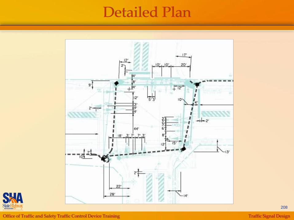
Detailed Plan
Verify feasibility of field-located equipment
Add dimensions to equipment and pavement
markings
Add Construction Detail Letters and Special
Note References
Office of Traffic and Safety Traffic Control Device Training Traffic Signal Design
208
Detailed Plan
Office of Traffic and Safety Traffic Control Device Training Traffic Signal Design
209
Construction Details
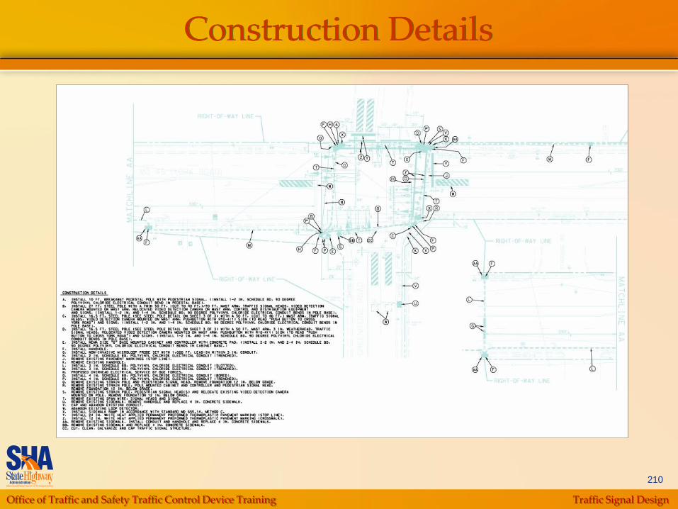
Provides sufficient information to guide the Contractor in constructing the project in accordance with the design
Use letter identification from A to ZZ, as many as needed, corresponding with the plan sheet
Initially, group notes according to proposed features (for example: poles, conduit, handholes, pavement markings, removal of existing devices, etc.)
Letters are shown in circles on the plan
Same letter may appear more than once (e.g.
install handhole note will appear many times)
Office of Traffic and Safety Traffic Control Device Training Traffic Signal Design
210
Construction Details
Office of Traffic and Safety Traffic Control Device Training Traffic Signal Design
211
Special NotesSample
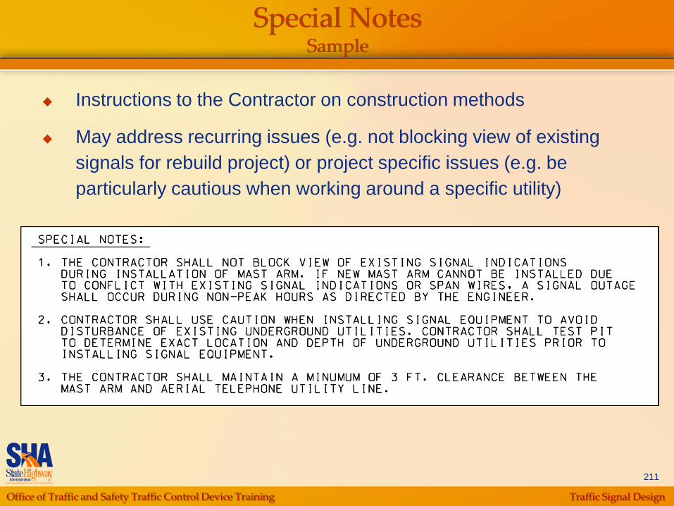
Instructions to the Contractor on construction methods
May address recurring issues (e.g. not blocking view of existing
signals for rebuild project) or project specific issues (e.g. be
particularly cautious when working around a specific utility)
Office of Traffic and Safety Traffic Control Device Training Traffic Signal Design
212
Revision Block Sample
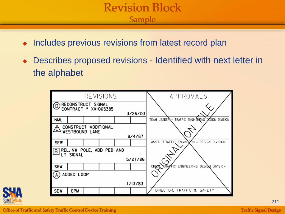
Includes previous revisions from latest record plan
Describes proposed revisions - Identified with next letter in
the alphabet
Office of Traffic and Safety Traffic Control Device Training Traffic Signal Design
213
General Notes Sample
Typical General Notes
Disclaimer regarding overhead/underground utility information
Instructions for sidewalk repair if damaged
Instructions for equipment removal
ADA/APS compliance notes
Foundations installed at proper grade

Office of Traffic and Safety Traffic Control Device Training Traffic Signal Design
214
Signal Plan Sheet

Office of Traffic and Safety Traffic Control Device Training Traffic Signal Design
215
Typical General Information Sheet

Office of Traffic and Safety Traffic Control Device Training Traffic Signal Design
216
Project DescriptionSample
Type of work planned
Intersection location and directional assumptions
Intersection operation
Controller requirements and phone line installation requirement
APS notes
Office of Traffic and Safety Traffic Control Device Training Traffic Signal Design
217
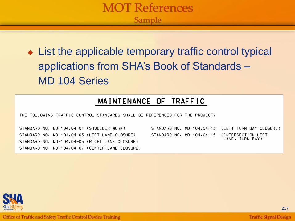
MOT ReferencesSample
List the applicable temporary traffic control typical
applications from SHA‟s Book of Standards –
MD 104 Series
Office of Traffic and Safety Traffic Control Device Training Traffic Signal Design
218
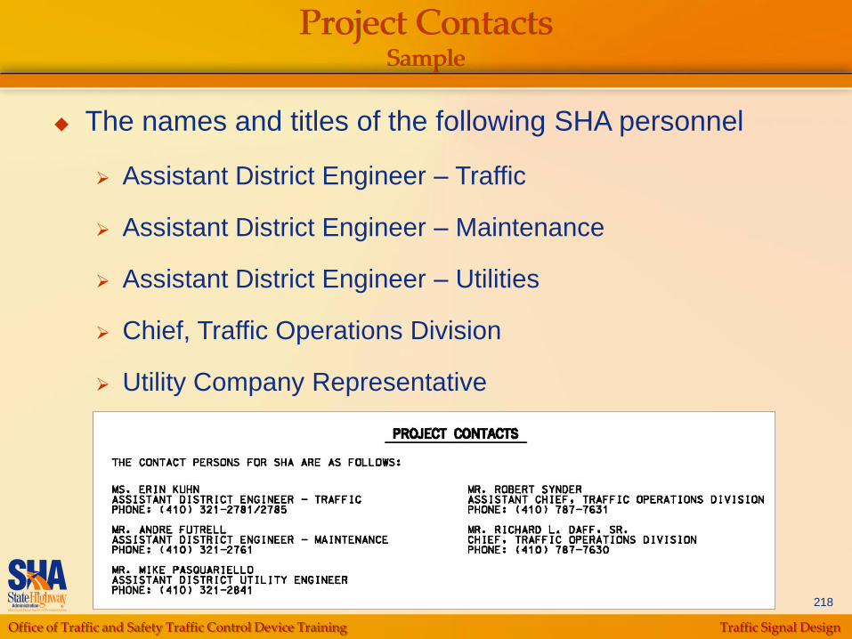
Project ContactsSample
The names and titles of the following SHA personnel
Assistant District Engineer – Traffic
Assistant District Engineer – Maintenance
Assistant District Engineer – Utilities
Chief, Traffic Operations Division
Utility Company Representative

Office of Traffic and Safety Traffic Control Device Training Traffic Signal Design
219
Signal Head Wiring
Use 7 conductor cable for combinations of 3, 4, or 5
section signal heads serving one direction
Use 5 conductor jumper cable for 3 section heads
For exclusive left-turn phasing, use (2) 7 conductor
cables, one for the thru heads and one for the turn
heads
Use 5 conductor cable for each pedestrian signal
head
Use 2 conductor cable for all pushbuttons
Office of Traffic and Safety Traffic Control Device Training Traffic Signal Design
220
Electrical Service Wiring
Coordinate with utility company to determine
the appropriate electrical service to request
Use (3) 1 conductor cable, No. 8 AWG-
THHN/THWN from metered service pedestal
to cabinet
Use (3) 1 conductor, 2/0 cables from metered
service pedestal to utility pole when getting
service from Pepco
Office of Traffic and Safety Traffic Control Device Training Traffic Signal Design
221
Detector Wiring
For Loop Detectors
Use a separate 2 conductor (Aluminum
shielded) cable for each loop detector
For Video Detection
Use control cable for each video detection
camera
Specify cable lead-in length required upto
500‟

Office of Traffic and Safety Traffic Control Device Training Traffic Signal Design
222
Wiring DiagramSample
Diagram shows electrical cable routing for:
Signal heads
Luminaries
Detectors
Push buttons
Power
Communications
Control cabinet

Office of Traffic and Safety Traffic Control Device Training Traffic Signal Design
223
Wiring DiagramSample
Office of Traffic and Safety Traffic Control Device Training Traffic Signal Design
224
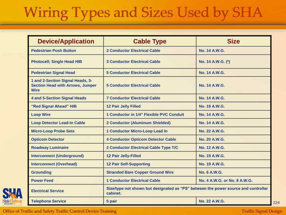
Wiring Types and Sizes Used by SHA
Device/Application Cable Type Size
Pedestrian Push Button 2 Conductor Electrical Cable No. 14 A.W.G.
Photocell; Single Head HIB 3 Conductor Electrical Cable No. 14 A.W.G. (*)
Pedestrian Signal Head 5 Conductor Electrical Cable No. 14 A.W.G.
1 and 2-Section Signal Heads, 3-
Section Head with Arrows, Jumper
Wire
5 Conductor Electrical Cable No. 14 A.W.G.
4 and 5-Section Signal Heads 7 Conductor Electrical Cable No. 14 A.W.G.
“Red Signal Ahead” HIB 12 Pair Jelly Filled No. 19 A.W.G.
Loop Wire 1 Conductor in 1/4" Flexible PVC Conduit No. 14 A.W.G.
Loop Detector Lead-In Cable 2 Conductor (Aluminum Shielded) No. 14 A.W.G.
Micro-Loop Probe Sets 1 Conductor Micro-Loop Lead In No. 22 A.W.G.
Opticom Detector 4 Conductor Opticom Detector Cable No. 20 A.W.G.
Roadway Luminaire 2 Conductor Electrical Cable Type T/C No. 12 A.W.G.
Interconnect (Underground) 12 Pair Jelly-Filled No. 19 A.W.G.
Interconnect (Overhead) 12 Pair Self-Supporting No. 19 A.W.G.
Grounding Stranded Bare Copper Ground Wire No. 6 A.W.G.
Power Feed 1 Conductor Electrical Cable No. 4 A.W.G. or No. 8 A.W.G.
Electrical ServiceSize/type not shown but designated as “PS” between the power source and controller
cabinet.
Telephone Service 5 pair No. 22 A.W.G.
Office of Traffic and Safety Traffic Control Device Training Traffic Signal Design
225
Grounding
Mast Arm Installation
Run continuous ground:
• Between control cabinet and handholes containing 110V
AC cables
• At the bases of mast arm pole structures
Span Wire Designs
Run continuous ground:
• From strain poles to the ground rod and nearest handhole
• From pedestal poles to the ground rod and nearest
handhole
Office of Traffic and Safety Traffic Control Device Training Traffic Signal Design
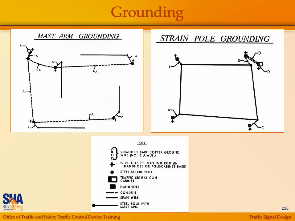
226
Grounding
Office of Traffic and Safety Traffic Control Device Training Traffic Signal Design
227
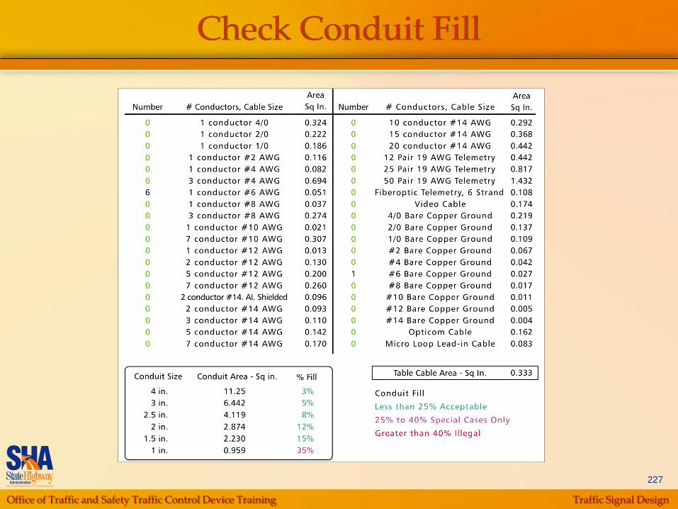
Check Conduit Fill

Office of Traffic and Safety Traffic Control Device Training Traffic Signal Design
228
Conduit Fill Limits
Office of Traffic and Safety Traffic Control Device Training Traffic Signal Design
229
Phase Chart
Along top of chart, show numbered signal heads
In left-hand column, list sequence of NEMA signal
phases and change intervals
In middle of table, show the signal indications for
each signal head by phase
In the far right-hand column, show movements
being served by each phase diagrammatically and
those that are stopped
Below chart, add special notes as required

Office of Traffic and Safety Traffic Control Device Training Traffic Signal Design
230
Phase ChartSample
Office of Traffic and Safety Traffic Control Device Training Traffic Signal Design
231
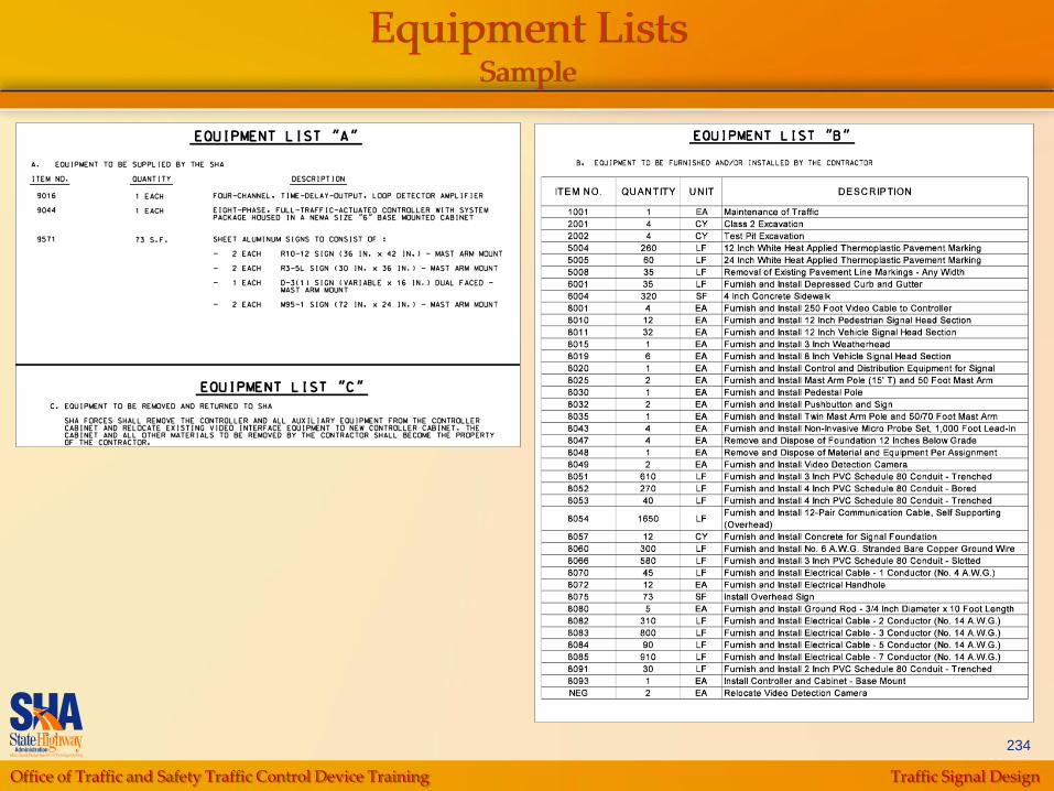
Equipment List
List A: Equipment Supplied by SHA
4-Channel Loop Detector Amplifiers
Cabinet Intersection Monitor (size 5 or 6)
Cabinet Master with Telemetry
Controller
Video Interface Equipment
Sheet Aluminum Signs (including hardware)

Office of Traffic and Safety Traffic Control Device Training Traffic Signal Design
232
Equipment List
List B: Equipment Supplied and/or Installed by the
Contractor
Format Varies by Construction Type:
• Areawide Contractor
• SHA Forces
• Insert Project
Items not appearing in Construction Details or
Wiring Details:
• Maintenance of Traffic
Office of Traffic and Safety Traffic Control Device Training Traffic Signal Design
233
Equipment List
List C: Equipment removed by Contractor
Used when existing Controller Equipment is being
replaced
Contact SHA Signal Maintenance Shop to pickup
Controller and Auxiliary Equipment
All other equipment shall become property of the
Contractor
Office of Traffic and Safety Traffic Control Device Training Traffic Signal Design
234
Equipment ListsSample
Office of Traffic and Safety Traffic Control Device Training Traffic Signal Design
235
Quantities and Cost Estimates
SHA “Category Codes”
Provides a list of item
numbers to be used
when preparing an
estimate (insert
projects)
Office of Traffic and Safety Traffic Control Device Training Traffic Signal Design
236
Quantities and Cost Estimates
Quantity Takeoff
Estimating Tables and Shortcuts
Documentation
Office of Traffic and Safety Traffic Control Device Training Traffic Signal Design
237
Quantities and Cost Estimates
Many items can be directly measured or counted
Signal Supports
Signal Heads per Section
Microloop Probe Sets
Cabinet/Controllers
Controller/Distribution equipment
Conduit
Sawcut
Luminaries
Bracket Arms
Removal of Marking (Letter or Arrow)
Signs
Pavement Markings
Office of Traffic and Safety Traffic Control Device Training Traffic Signal Design
238
Quantities and Cost Estimates
Cable Measurements
Use total measured quantity plus 10%
(accounts for handholes, cable slack,
connections, splices, and drip loops)
Include pole height in the measurements
when cable runs from ground level to
overhead and sag on span wire
Loop detector measurements
Office of Traffic and Safety Traffic Control Device Training Traffic Signal Design
239
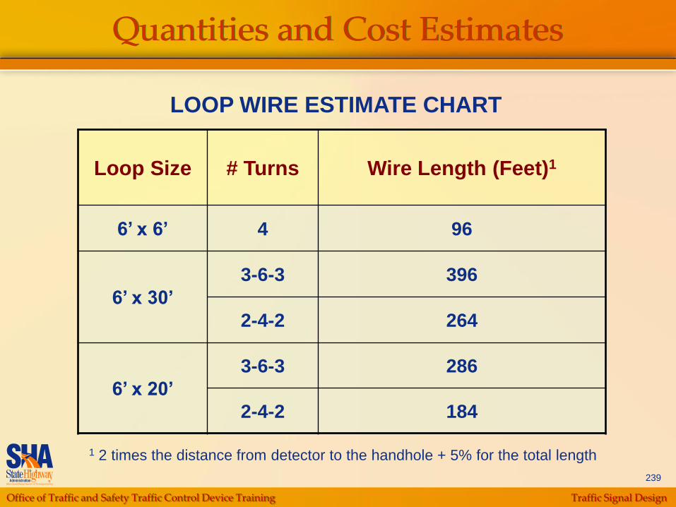
Quantities and Cost Estimates
LOOP WIRE ESTIMATE CHART
Loop Size # Turns Wire Length (Feet)1
6’ x 6’ 4 96
6’ x 30’
3-6-3 396
2-4-2 264
6’ x 20’
3-6-3 286
2-4-2 184
1 2 times the distance from detector to the handhole + 5% for the total length
Office of Traffic and Safety Traffic Control Device Training Traffic Signal Design
240
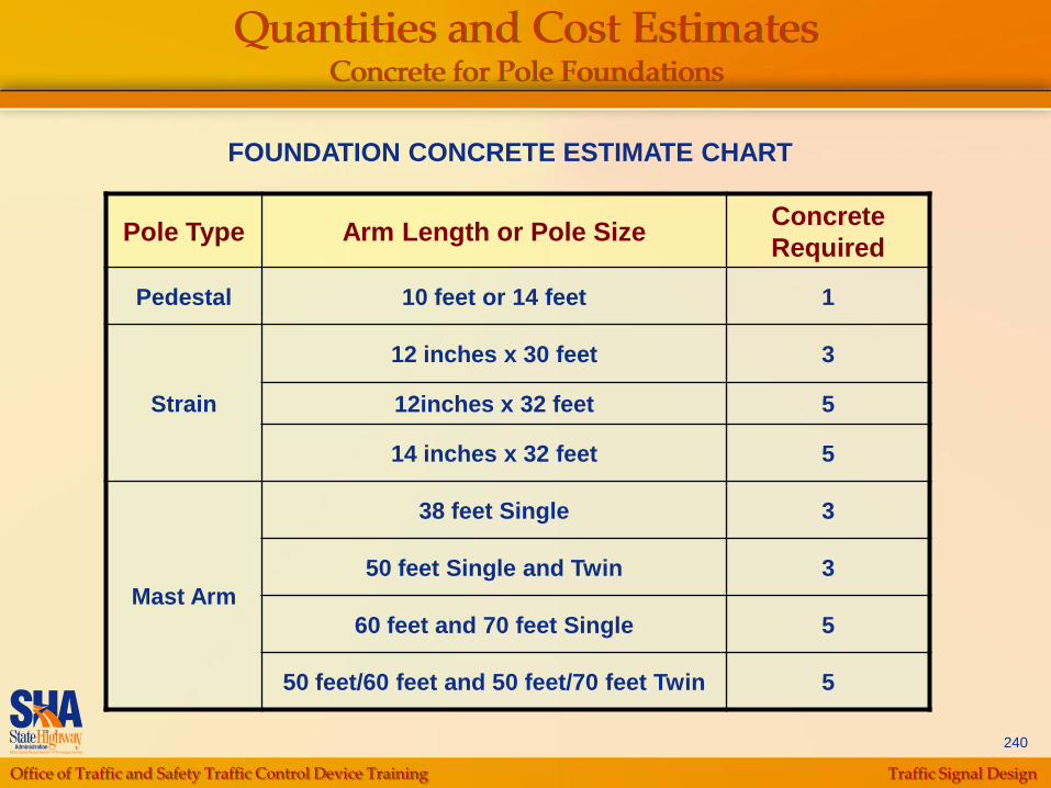
Quantities and Cost EstimatesConcrete for Pole Foundations
FOUNDATION CONCRETE ESTIMATE CHART
Pole Type Arm Length or Pole SizeConcrete
Required
Pedestal 10 feet or 14 feet 1
Strain
12 inches x 30 feet 3
12inches x 32 feet 5
14 inches x 32 feet 5
Mast Arm
38 feet Single 3
50 feet Single and Twin 3
60 feet and 70 feet Single 5
50 feet/60 feet and 50 feet/70 feet Twin 5

Office of Traffic and Safety Traffic Control Device Training Traffic Signal Design
241
Quantities and Cost Estimates
Wood Posts
Required length per post equals
height of the sign + 7 feet (clearance
to ground) + 5 feet for 4” x 4” or 4” x
6” posts or 6 feet for 6” x 6” or 6” x 8”
posts (embedment).
Round up to the next whole number.
Office of Traffic and Safety Traffic Control Device Training Traffic Signal Design
242
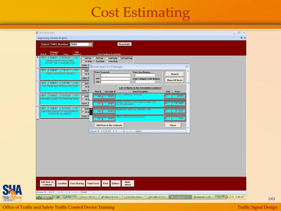
Cost Estimating
Equipment List A:
Use the latest published rates from TEDD
Equipment List B:
Construction by areawide Contractor
• Use contract bid prices
Construction by roadway Contractor (insert project)
• Use SHA Price Index and Bid Tabulations from recent contracts
• Estimator
• Industry trends
Office of Traffic and Safety Traffic Control Device Training Traffic Signal Design
243
Cost Estimating
Office of Traffic and Safety Traffic Control Device Training Traffic Signal Design
244
Specifications
Standard Specifications
Special Provisions
Spec Manager
Shelf Specifications
Interim Specification Amendments (ISAs)
Office of Traffic and Safety Traffic Control Device Training Traffic Signal Design
245
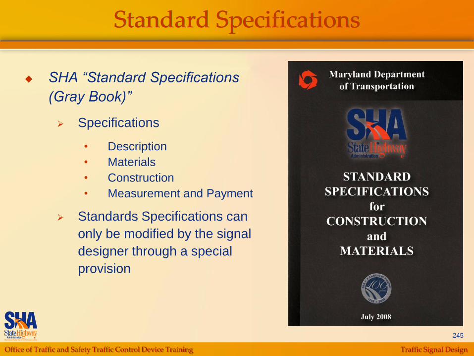
Standard Specifications
SHA “Standard Specifications
(Gray Book)”
Specifications
• Description
• Materials
• Construction
• Measurement and Payment
Standards Specifications can
only be modified by the signal
designer through a special
provision
Office of Traffic and Safety Traffic Control Device Training Traffic Signal Design
246
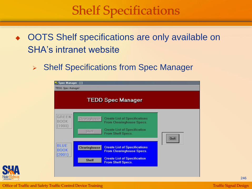
Shelf Specifications
OOTS Shelf specifications are only available on
SHA‟s intranet website
Shelf Specifications from Spec Manager

Office of Traffic and Safety Traffic Control Device Training Traffic Signal Design
247
FileName Description Section No
107MOD2001AW.DOC SECTION 107 CONSTRUCTION STAKEOUT 107
107MOD2001INSERT.DOC SECTION 107 CONSTRUCTION STAKEOUT 107
804.DOC SECTION 804 - GROUNDING 804
806MOD2001.DOC SECTION 806-LUMINAIRES AND LAMPS 806
BALANCE.DOCCATEGORY 950 - TRAFFIC MATERIALS
SECTION 950.15 TRAFFIC SIGNAL HEADS950
CATCUMOD2001.DOCCATEGORY 800 - TRAFFIC
CATALOG CUTS AND WORKING DRAWINGS800
DUCT.DOC SECTION 950.06-ELECTRICAL CABLE AND WIRE 950
F&IMAST2003.DOCCATEGORY 800 - TRAFFIC - MAST ARMS AND MAST ARM POLES -
SINGLE, TWIN AND TRIPLE800
F&IPEDL2003.DOCCATEGORY 800 - TRAFFIC - GALVANIZED TRAFFIC SIGNAL
PEDESTAL POLES AND TRANSFORMER BASES800
F&ISTRA2003.DOCCATEGORY 800 - TRAFFIC - GALVANIZED TRAFFIC SIGNAL
STRAIN POLES800
FOUNDATIONS.DOC
CATEGORY 800 - TRAFFIC - SECTION 801 - CONCRETE
FOUNDATIONS (NOTE: CORRECTION REGARDING ANCHOR
BOLTS)
801
INTERIMAUDIBLEPED.DOCCATEGORY 800 - TRAFFIC - AUDIBLE/TACTILE PEDESTRIAN
PUSHBUTTON STATION AND SIGNS800
LED_SIGNALS.DOC CATEGORY 800 - TRAFFIC - LED TRAFFIC SIGNAL MODULES 800
OOTS Shelf Specifications
Office of Traffic and Safety Traffic Control Device Training Traffic Signal Design
248
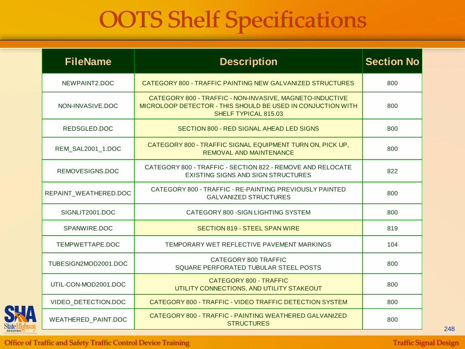
OOTS Shelf Specifications
FileName Description Section No
NEWPAINT2.DOC CATEGORY 800 - TRAFFIC PAINTING NEW GALVANIZED STRUCTURES 800
NON-INVASIVE.DOC
CATEGORY 800 - TRAFFIC - NON-INVASIVE, MAGNETO-INDUCTIVE
MICROLOOP DETECTOR - THIS SHOULD BE USED IN CONJUCTION WITH
SHELF TYPICAL 815.03
800
REDSGLED.DOC SECTION 800 - RED SIGNAL AHEAD LED SIGNS 800
REM_SAL2001_1.DOCCATEGORY 800 - TRAFFIC SIGNAL EQUIPMENT TURN ON, PICK UP,
REMOVAL AND MAINTENANCE800
REMOVESIGNS.DOCCATEGORY 800 - TRAFFIC - SECTION 822 - REMOVE AND RELOCATE
EXISTING SIGNS AND SIGN STRUCTURES822
REPAINT_WEATHERED.DOCCATEGORY 800 - TRAFFIC - RE-PAINTING PREVIOUSLY PAINTED
GALVANIZED STRUCTURES800
SIGNLIT2001.DOC CATEGORY 800 -SIGN LIGHTING SYSTEM 800
SPANWIRE.DOC SECTION 819 - STEEL SPAN WIRE 819
TEMPWETTAPE.DOC TEMPORARY WET REFLECTIVE PAVEMENT MARKINGS 104
TUBESIGN2MOD2001.DOCCATEGORY 800 TRAFFIC
SQUARE PERFORATED TUBULAR STEEL POSTS800
UTIL-CON-MOD2001.DOCCATEGORY 800 - TRAFFIC
UTILITY CONNECTIONS, AND UTILITY STAKEOUT800
VIDEO_DETECTION.DOC CATEGORY 800 - TRAFFIC - VIDEO TRAFFIC DETECTION SYSTEM 800
WEATHERED_PAINT.DOCCATEGORY 800 - TRAFFIC - PAINTING WEATHERED GALVANIZED
STRUCTURES800
Office of Traffic and Safety Traffic Control Device Training Traffic Signal Design
249
Interim Specification Amendments
Interim Specification Amendments
Inserts are available from SHA‟s external
website – http://www.sha.state.md.us/
Office of Traffic and Safety Traffic Control Device Training Traffic Signal Design
250
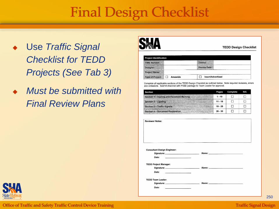
Final Design Checklist
Use Traffic Signal
Checklist for TEDD
Projects (See Tab 3)
Must be submitted with
Final Review Plans