SPM Bi-Directional Communication Protocol Operating instructions

Welcome message from author
This document is posted to help you gain knowledge. Please leave a comment to let me know what you think about it! Share it to your friends and learn new things together.
Transcript

SPM Bi-DirectionalCommunication Protocol
Operating instructions

Your Uptime Is Our Top Priority
Congratulations on your purchase of the SPM Bi-Directional Communications Protocol. It will provide you with years of reliable service. Because your uptime is our top priority, Zellweger Analytics, Inc. provides you with both local service and a 24-hour Emergency Service Hotline. During Business Hours: Zellweger Analytics, Inc. Product Headquarters: (Toll-Free) 800-323-2000 847-955-8200 Mid-Atlantic: 610-560-6000 Gulf Coast: 512-452-9718 Southwest: 760-942-3142 West Coast: 408-261-8802 Northwest: 503-639-3202 Zellweger Analytics, Ltd. (UK) 44-1-202-676-161 24-Hour Emergency Hotline: 847-634-2840 Record your serial number and installation date here for easy reference:
(To save time when calling for service, please have the serial number of your instrument available.)

SPM Protocol License Agreement
Carefully review the following terms and conditions before proceeding. In the event that you do not agree to these terms and conditions, you must return this package intact. By not returning this package, you indicate your acceptance of all terms and conditions stipulated herein. Furthermore, retaining it indicates and acknowledges that you have read this agreement, understand it, and agree to its terms and conditions. License Zellweger Analytics grants to the user, in exchange and in consideration for applicable fees, a license for the use of the SPM protocol, the right to use and the SPM protocol definition of which is supplied to you in a separate document. This license grants you the right of knowledge and use of the SPM protocol. This license does not grant ownership of the subject. This license agreement is for a single SPM instrument, and does not imply multiple or site license. In Zellweger Analytic’s granting and the users’ acceptance of this license, this license agreement is binding. This license is granted to you, the purchaser, and you may not sublicense, transfer or assign this license. You may not transfer, copy or divulge any part of this protocol technique or knowledge except as expressly provided for in this agreement. Term This agreement shall be in effect until terminated. Either party may terminate this agreement. All materials relating to this agreement shall be returned or destroyed upon the termination of this agreement. Warrants Zellweger Analytics warrants this package to the extent as it is set forth in the SPM protocol document and any other supplied documentation. Zellweger Analytics disclaims all warranties not explicitly stated within this agreement. Zellweger Analytics does not warrant the operation will be uninterruptible or error-free. Furthermore, Zellweger Analytics does not guarantee the SPM protocol will meet your requirements. The use and results the USER obtains are the responsibility of the USER. In no event will Zellweger Analytics or its suppliers or vendors be liable for - to you or any other person - for any damages, expenses, interruption of business, or other damages arising out of use or the inability to use the SPM protocol. Notes SPM refers to any of the SPM instruments Zellweger Analytics has designed and markets, and is the trademark of the family
Zellweger Analytics, Inc. SPM Communications Protocol
i Rev.3.1 (6/95)
Section 1: Introduction 1.1 Overview ………………………..................................................... 1-1 1.2 Terms ………………………………………………………………… 1-1
Section 2: SPM 2.1 Operation from the Communication Port …………………………. 2-1 2.2 Instrument Port Configuration ……………………………………... 2-1 2.3 Communication Port Time-out …………………………………….. 2-1
Section 3: Protocol Specifics 3.1 Data and Packets …………………………………………………..... 3-1 3.2 Check-Character (Checksum) ……………………………………… 3-1 3.3 ACK/NAK Handshake ……………………………………………...... 3-2
Section 4: Operation with an SPM 4.1 SPM Power-up ………………………………………………………. 4-1 4.2 Normal Analysis Messages ……………………………………....... 4-1 4.3 Errors and Faults ……………………………………………………. 4-1 4.4 Commands ………………………………………………………....... 4-1 4.5 Responses …………………………………………………………… 4-1
Appendix A: Pin-out and Wiring Configurations
Appendix B: Packet Format B.1 Format ……………………………………………………………….. B-1 B.2 Graphic Style ………………………………………………………... B-1 B.3 Typical Command and Data Set ………………………………….. B-1
Appendix C: Valid Commands and Responses C.1 SPM Remote Device Communications Command ………………. C-1 Codes and Parameters C.2 Valid Response Packets ……………………………………………. C-2 C.3 SPM Protocol Command Parameter Format ……………………... C-3
Table of Contents

Zellweger Analytics, Inc. SPM Communications Protocol
ii Rev.3.1 (6/95)
Check-Character ………………………………………………………………………. 3-1 COMMUNICATION ……………………………………………………………………. 1-1 CONFIGURATION …………………………………………………………………….. 2-1 Data ……………………………………………………………………………………… 3-1 HANDSHAKE …………………………………………………………………………… 1-1 Manual …………………………………………………………………………………… 1-1 OPERATION ……………………………………………………………………………. 2-1 PACKETS ……………………………………………………………………………….. 3-1 PIN-OUT …………………………………………………………………………………. A-1 Terms …………………………………………………………………………………….. 1-1 BYTE …………………………………………………………………………….. 1-1 COMMUNICATION …………………………………………………………….. 1-1 DATA …………………………………………………………………………….. 1-1 HANDSHAKE …………………………………………………………………… 1-1 PACKET …………………………………………………………………………. 1-1 PROTOCOL ……………………………………………………………………... 1-1 TIME-OUT ……………………………………………………………………….. 1-1
TIME-OUT ……………………………………………………………………………… 1-1, 2-1
Index

Zellweger Analytics, Inc. SPM Communications Protocol
1-1 Rev.3.1 (6/95)
1.1 Overview Your SPM instrument is equipped with a serial remote device communication port to which you have purchased a protocol license. The information that is contained in this manual and is available at this communication port is intended to help you monitor SPM operation from another location. It will also allow you to gather gas concentration data for any use or analysis. This manual will supply you with the technical information for the use and correct operation of the SPM protocol, which will allow you to communicate with this sophisticated modular instrument. The SPM protocol was designed and developed by Zellweger Analytics, and is considered proprietary to Zellweger Analytics. The following pages will describe to you what protocol is, what the pieces are and how it is used. It will also offer suggestions on most effective use. The SPM protocol has been designed to be flexible and efficient. The protocol is a byte-wise protocol. That is, it is communicating information transferring bytes of data back and forth between the instrument and your computer equipment. A group of bytes is referred to as a “packet”.
1.2 Terms This manual will be using the following terms when describing the SPM protocol to you. BYTE: refers to a collection of 8 bits (or pieces) of information. A BYTE refers to this information as a single thing or quantity.
COMMUNICATION: refers to the act or process of passing digital information between two points. DATA: refers to the information that is transferred between the SPM and your equipment. DATA refers to the information contained within a packet, whether it be concentration, date or some other piece of information. EQUIPMENT: refers to the equipment that you plan to use to communicate with the SPM. HANDSHAKE: refers to the process of acknowledging a communication has been received. The SPM uses ACK/NAK responses. INSTRUMENT: refers to the SPM instrument with which you intend to interface (or communicate). PACKET: refers to the block of information that is passed between the instrument and your equipment. A PACKET is made from many bytes of information. PROTOCOL: refers to the manner in which the data is transferred and the format used to transfer the data. The SPM PROTOCOL refers to the PACKET of BYTES the SPM recognizes. TIME-OUT: refers to the maximum amount of time that SPM instrument allows for the equipment to respond to a packet sent from the instrument. If the time period is exceeded, then the SPM will ignore any additional responses to it. The SPM will not go into a fault condition or fault state. The SPM will not deactivate the communication port, but rather will transmit more data when it is appropriate.
Section 1: Introduction

Zellweger Analytics, Inc. SPM Communications Protocol
2-1 Rev.3.1 (6/95)
2.1 Operation from the Communication Port Access to the SPM protocol is through the Amphenol (Bendix) connector that is located on the side of the SPM (located inside of purged units). Your SPM instrument communicates through this port. This port also allows your equipment to monitor what the SPM instrument is actually doing from a remote area. This port is designed to be bi-directional, that is, it will both send and receive data. The SPM instrument’s communication port is indicated by a label “RS-422 output”. The signals that are present on the connector conform to RS-422 specifications. The pin-out designations may be found in the back in Appendix A. Your SPM will communicate at baud rate of 9600 baud (sometimes specified as 9.6k baud). This is a fixed value, and cannot be changed or adjusted by the user. The SPM uses 8 bits per character, with one (1) stop bit and NO parity. The SPM protocol has been designed to be flexible and efficient. The protocol is a byte-wise protocol. It communicates information by transferring bytes of data back and forth between the instrument and your computer equipment. A group of bytes is referred to as a “packet”. The communication port in the SPM can only exchange one piece of information at a time. The SPM will only accept a packet after it has sent a packet. It will ignore any packet that your equipment sends that is not in response to an SPM packet. The SPM protocol is also used by the available compliment of remote devices for the SPM. For example, the TGM (Toxic
Gas Monitoring) System uses the SPM remote device communication port. Additionally, the SPM protocol has been designed to support multiple devices from its port, if required.
2.2 Instrument Port Configuration The port is configured to be bi-directional and will result in the instrument periodically “polling” the user’s equipment. In this mode, the SPM expects the user’s equipment to be “on-line” and active at all times. That is, your equipment must accept and respond to each SPM command. This polling is the user’s opportunity to give an instruction or command to the SPM.
2.3 Communication Port Time- out The SPM allows the user’s equipment to issue a response back to the SPM for each communication that occurs. After each query, the SPM waits for one second for the response. This period is known as a time-out period. If your equipment fails to send an acknowledgement of some form to the SPM within this time-out period, the SPM will ignore all further communications sent to it until the SPM institutes another transmission.
• Note The SPM will perform one re-transmission of the data.
If the SPM is configured to insure communications at regular intervals, and if it has been more than three seconds since the last packet was sent, than the SPM will send a “No Operation” (NOP) packet.
Section 2: SPM

Zellweger Analytics, Inc. SPM Communications Protocol
3-1 Rev.3.1 (6/95)
This section will discuss data and packets, check-character (CHECKSUM) and ACK/NAK handshakes.
3.1 Data and Packets A byte is a piece of data. It is a way to indicate information. It is composed of 8 bits of information. A bit is the smallest possible piece of information. There can only be two possible values for a bit: 1 or 0 (true or false). A byte can have a numeric value of anything between 0 and 255. The number may be interpreted in a manner other than a number, for example as a letter. Bytes are often represented as hexadecimal or base 16 numbers. In hexadecimal, the values 10 through 15 are represented by the letters A through F. For example, 13 is represented by 0D in hexadecimal and 27 is represented by 1B. Using ASCII characters where HEX 65 (HEX 41) was the letter “A”, HEX 66 (HEX 42) was the letter “B”, HEX 67 (HEX 43) was a “C” and so on, a message could be written as these numbers, and each number would be a byte. For example, to say “BAD” would be 66, 65, 68 (HEX 42, 41, 44). The collection of the above three bytes (which made our message) may be referred to as a packet, as these bytes are always associated with each other. Just as all words are not the same length (number of letters), packets may vary in length. One way to denote the size of the words is to put the number of letters you have in your word as the first number in your packet. Your data packet containing the word (or command) “BAD” will be 3, 66, 65, 68.
3.2 Check-Character (Checksum) During the transmission of the packet, an error may change the value of the data. In our example, for instance, the packet of 3, 66, 65, 68 is now 3, 66, 61, 68. One way to determine that the numbers you receive are the same as the numbers that were sent is to add a check-character to the packet. A check-character is a method of assigning a value to the packet to check if any of your bytes have been modified. If all the data bytes were to be added together and this sum made into a byte, that byte could be called a check-character, or sometimes called a checksum. For your packet 3+66+65+68 is equal to 202. You would place this number at the end of your packet: 3, 66, 65, 68, 202. By adding all the bytes together, the sum should match the value of the check-character. An error is indicated if the two numbers do not match each other. If there is an error, then either some of the data has been modified, or the check-character itself was modified. For the SPM, the check-character is the negated sum of all the bytes in your packet. As above, our packet would be 3, 66, 65, 68, -202. For this packet, the sum of the bytes added to the check-character must equal zero (0). Any other result is indicating that there is an error with your data. The SPM’s data contained within the packet is interpreted in a somewhat different manner than the above example. The data is composed of two sections: a command and one or more parameters. The command indicates the type of data. Another way to view this is: the command tells the type of packet and parameters.
Section 3: Protocol Specifics

Zellweger Analytics, Inc. SPM Communications Protocol
3-2 Rev.3.1 (6/95)
Each and every packet will contain at least 4 data bytes: SPM DATE & TIME stamp. This data gives a date and time reference. You should insure that your SPM’s date and time are set accurately. An example of a typical communication is: a packet with a command of 61 (hexadecimal value) is a FAULT type packet. The 61 indicates that this packet has been sent due to a fault. See Table 3-1. This packet is for an instrument fault. The actual fault type is found in the byte labeled as “FAULT”. The remainder of the packet is 09 (HEX) for the number of bytes (9) found in this packet, DATE and TIME stamped for your reference. Every packet the SPM sends contains an address, a length, a command and associated parameters and a check-character. The SPM assumes that all remote devices occupy address (HEX) 4D.
The SPM has been assigned an address of (HEX) 4C. It only recognizes this address. 3.3 ACK/NAK Handshake The SPM implements a handshake scheme between itself and any other piece of equipment wishing to communicate with the SPM. The most common response back to the instrument is an “ACK”. ACK stands for ACKnowledge. Your equipment sends it back to tell the SPM that the packet is ok. If, however, the check-character did not match, you may elect to send back a “NAK”, which stands for NegAtive acKnowledge. A NAK indicates that a data packet has been received but the check-character did not match with the packet data. The SPM will then re-send the packet to your equipment. An ACK packet would be (all HEX): 4C, 04, 20, 90. (4C+4+20+90=0)
Table 3-1
Fault Packet
09 (HEX) 61 (HEX) DATE (2 bytes) TIME (2 bytes) FAULT NO. (1 byte)

Zellweger Analytics, Inc. SPM Communications Protocol
4-1 Rev.3.1 (6/95)
4.1 SPM Power-up When the SPM has power applied to it, the instrument will first go through its power-up and diagnostic phases and steps. These steps are indicated when the SPM is performing its light and valve sequencing, and by the messages the SPM displays. Upon completion of this, the SPM will activate the communication port. Please refer to your SPM manual for further details of the operations.
4.2 Normal Analysis Messages In MONITOR Mode, the SPM will send gas concentration and alarm data out. This data will be sent at the completion of the current analysis cycle. Each packet of gas concentration information will contain an alarm flag. When this flag is zero, there is no alarm for this current piece of data (that is, this point does not have a gas concentration in excess of either alarm set points). In addition, it will send the time weighted average (TWA) information, calibration information and other data. The SPM will also send out any faults and other warnings, as appropriate.
4.3 Errors and Faults All errors and faults the SPM detects are sent out the remote device communication port. This includes all levels: warnings, errors or faults. Your equipment receives and processes the data and produces the results you require.
4.4 Commands Your SPM will send any one of a number of commands to your equipment. These commands are detailed in Appendix C of this manual. They are listed by both the command number and by name. All errors and faults are included in the set of possible commands. The SPM will accept and process commands that your equipment may send to the instrument. These commands are also detailed in Appendix C. Your equipment may also send a “RESET” to the SPM, which functions as if the “RESET” button were pushed.
4.5 Responses The SPM will accept a return communication for any packet it sends. Your equipment may respond back with an ACK, NAK, RESET packet or diagnostic dump. The ACK packet is an acknowledgement to the SPM. It indicates to the SPM that the last communication was correctly received. The SPM will accept the ACK and no further action will occur. The other packet is the NAK. This type of packet is translated as a NAK. It means that the last packet was not received correctly. Either the check-character did not match or there was some other communication error (framing, for example). The SPM re-sends the last packet if it receives an NAK response. The SPM resends the message once. If the resend fails, the SPM will not communicate (it will wait) until the next regular communication activity occurs.
Section 4: Operation with an SPM

Zellweger Analytics, Inc. SPM Communications Protocol
A-1 Rev.3.1 (6/95)
The 9 pin connector, marked as “RS-422 OUTPUT” is the connector you use. Often it is referred to as a port or as the communication port. It is a DB-9F form. Table A-1 lists the signals that are available at the Network Interface connector.
Table A-1
Output Signals
Pin Designations
Standard SPM Z-Purge SPM TGMS Signal
A 1 1 Ground
D 6 6 Transmit +
E 7 7 Transmit -
F 8 8 Receive +
G 9 9 Receive -
Appendix A: Pin-out and Wiring Configurations

Zellweger Analytics, Inc. SPM Communications Protocol
B-1 Rev.3.1 (6/95)
B.1 Format An SPM packet will follow the format described in Table B-1 when transmitting.
Byte No. Function
1 Device Address. The address or “name” of the device this packet is directed to. It is always (HEX) 4D.
2 Packet Length (n). The length is the number of bytes to be found in this packet. It includes the address byte and the check-character byte and all bytes between.
3 through (n-1) Command and Data. The remaining bytes within the packet are data bytes.
n Check-character. This byte is the last character in the packet. Its value is equal to the negated summation of all previous bytes in the packet. It is the negative checksum of the packet.
Table B-1
SPM Transmission Format
B.2 Graphic Style Graphically, the packet appears as shown in Table B-2.
Byte 1 Byte 2 Byte 3 through (n-1) Byte n
Device Address Packet Length Commands and Data Set Check Character
Table B-2
SPM Graphic Style
B.3 Typical Command and Data Set Table B-3 shows the typical command and data sets.
Command Date * Time * Parameter(s)
1 Byte 2 Bytes 2 Bytes (No of bytes is command dependent)
Table B-3
Command and Data Set
* In IBM-PC style format.
Appendix B: Packet Format

Zellweger Analytics, Inc. SPM Communications Protocol
C-1 Rev.3.1 (6/95)
C.1 SPM Remote Device Communications Command Codes and Parameters Table C-1 is a list of valid commands that the SPM will issue. All command codes in the following table are hexadecimal. The length of each parameter is indicated. This list is subject to change without notice.
Command Code (Hex) Command Description Parameters (No of Bytes)
28 NOP (No Operation) Date (2) Time (2)
30 Gas Concentration or Alarm
Date (2) Time (2) Zellweger Gas No (1) Format Code (1) Concentration (2) Current Loop Drive (1) Alarm Flag (1)
32 Time Weighted Average (TWA) Gas Concentration
End Date (2) End Time (2) Start Date (2) Start Time (2) Zellweger Gas No (1) Format Code (1) TWA (2)
35 SPM Information
(Provision for special/SER are needed)
Date (2) Time (2) Revision, Major (1) Revision, Minor (1) EPROMs Checksum (2) Zellweger Gas No (1) SPM Serial No (2) Option Flags (1)
61 Fault Date (2) Time (2) SPM Fault No (1)
Table C-1
Valid SPM Commands
Appendix C: Valid Commands and Responses

Zellweger Analytics, Inc. SPM Communications Protocol
C-2 Rev.3.1 (6/95)
C.2 Valid Response Packets Table C-2 lists the valid response packets to the SPM.
Command Code (Hex) Command Command Description
20 ACK (Acknowledgement) Indicates packet was received properly.
21 NAK (Negative Acknowledgement)
Indicates the packet was not valid. Will cause SPM to resend the last packet of information.
30 RESET Will cause SPM to do an Alarm or Fault Reset, as if the RESET button were momentarily pressed.
31 Diagnostic Dump The SPM will transmit the software version and checksum of the EPROM via command 35 (above).
Table C-2
Valid Response Packets to the SPM
Zellweger Analytics, Inc. SPM Communications Protocol
C-3 Rev.3.1 (6/95)
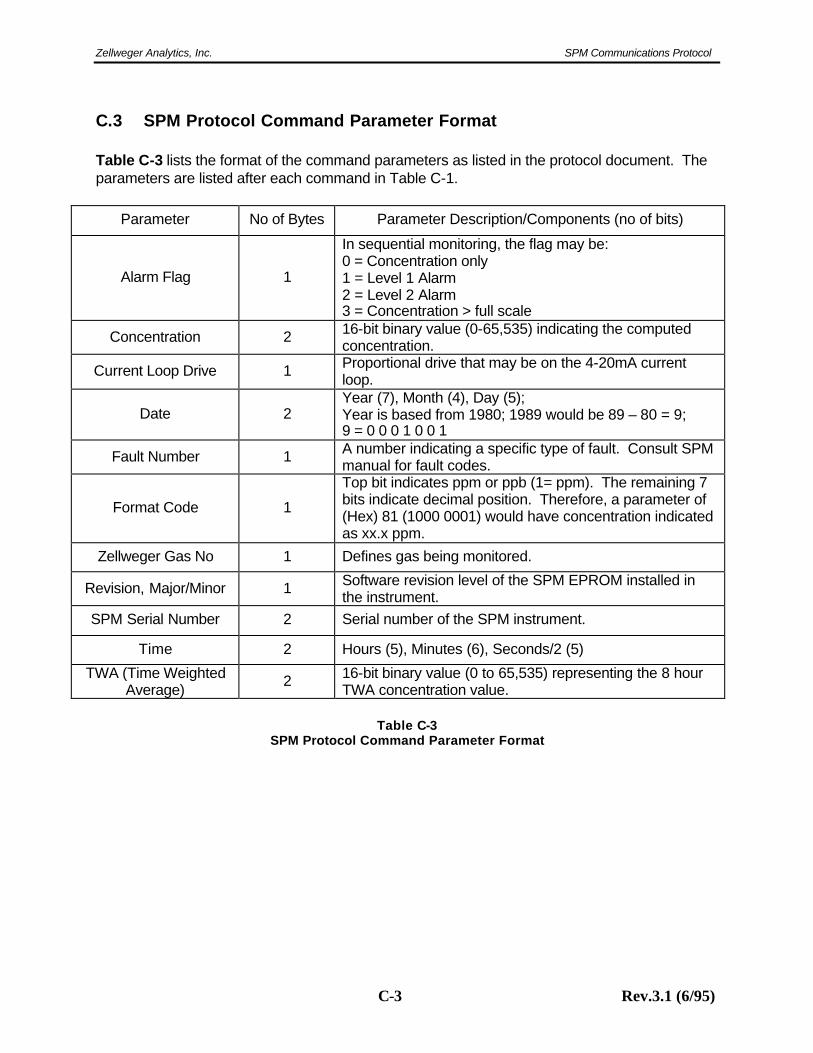
C.3 SPM Protocol Command Parameter Format Table C-3 lists the format of the command parameters as listed in the protocol document. The parameters are listed after each command in Table C-1.
Parameter No of Bytes Parameter Description/Components (no of bits)
Alarm Flag 1
In sequential monitoring, the flag may be: 0 = Concentration only 1 = Level 1 Alarm 2 = Level 2 Alarm 3 = Concentration > full scale
Concentration 2 16-bit binary value (0-65,535) indicating the computed concentration.
Current Loop Drive 1 Proportional drive that may be on the 4-20mA current loop.
Date 2 Year (7), Month (4), Day (5); Year is based from 1980; 1989 would be 89 – 80 = 9; 9 = 0 0 0 1 0 0 1
Fault Number 1 A number indicating a specific type of fault. Consult SPM manual for fault codes.
Format Code 1
Top bit indicates ppm or ppb (1= ppm). The remaining 7 bits indicate decimal position. Therefore, a parameter of (Hex) 81 (1000 0001) would have concentration indicated as xx.x ppm.
Zellweger Gas No 1 Defines gas being monitored.
Revision, Major/Minor 1 Software revision level of the SPM EPROM installed in the instrument.
SPM Serial Number 2 Serial number of the SPM instrument.
Time 2 Hours (5), Minutes (6), Seconds/2 (5)
TWA (Time Weighted Average) 2 16-bit binary value (0 to 65,535) representing the 8 hour
TWA concentration value.
Table C-3 SPM Protocol Command Parameter Format
Find out more
www.honeywellanalytics.com
Customer business centre
Europe and the rest of the world
Honeywell Analytics AG
Wilstrasse 11-U11
CH-8610 Uster
Switzerland
Tel: +41 (0)44 943 4300
Fax: +41 (0)44 943 4398
Customer business center
Americas
Honeywell Analytics Distribution, Inc.
400 Sawgrass Corporate Pkwy
Suite 100
Sunrise, FL 33325
USA
Tel: +1 954 514 2700
Toll free: +1 800 538 0363
Fax: +1 954 514 2784
www.honeywell.com
P/N 971075
Rev 3.1 (12/05)
© 2005 Honeywell Analytics 11241
Please Note:While every effort has been made to ensure accuracy in this publication, no responsibility can be accepted for errors or omissions. Data may change, as well as legislation, and you are strongly advised to obtain copies of the most recently issued regulations, standards, and guidelines.This publication is not intended to form the basis of a contract.© 2005 Honeywell Analytics
Related Documents