11 Synthesis Parameters W hat’s the difference between a synthesizer and a sampler? A sampler uses recorded waveforms as the basis of its sounds, and a synth uses electronically or digitally generated ones. That’s the exact definition; it is important to distinguish the early digital samplers and synths that were becoming popular from the analog synthesizers that preceded them. In fact, there’s never really been a rock-solid line between digital synths and samplers. Samplers include at least the basic filtering and LFOs (low frequency oscillators) found on synths; many synths use sampled waveforms. Some synths can record or import samples and process them; synths and samplers both can use sampled synthetic waveforms, making the distinction some- what academic. There’s a lot of crossover, to say nothing of numerous hybrid hardware and soft- ware synths. Still, there are many instruments that are clearly one or the other. While the samplers we’ve been working with in this book are unmistakably samplers rather than synths, they’re all capable of making wild and wacky sounds that would make anyone listening say “synthesizer.” In this chapter, we’ll look briefly at how to make electronic effects with the samplers’“synth” parameters. The Tools: Filters, Envelopes, LFOs, and the Modulation Matrix These tools are essentially the same ones found in conventional subtractive analog synthesizers— the ones that were around before the digital revolution. They’re also fundamental to samplers. Filters Depending on their type, filters simply block or pass frequencies within or outside a given range; this range is called the cutoff in samplers and synths (the cutoff parameter generally incorporates the passband and the stopband). Which filter type you choose depends on what you want to do. The simplest ones are lowpass and highpass filters, meaning that they roll off the highs or lows, respectively, on the appropriate side of the corner frequency. There are also bandpass filters that do just what the name implies: pass a prescribed band of frequencies. Allpass filters reverse the phase. 225

Welcome message from author
This document is posted to help you gain knowledge. Please leave a comment to let me know what you think about it! Share it to your friends and learn new things together.
Transcript

11 Synthesis Parameters
What’s the difference between a synthesizer and a sampler? A sampler uses recorded
waveforms as the basis of its sounds, and a synth uses electronically or digitally
generated ones. That’s the exact definition; it is important to distinguish the early
digital samplers and synths that were becoming popular from the analog synthesizers that
preceded them.
In fact, there’s never really been a rock-solid line between digital synths and samplers. Samplers
include at least the basic filtering and LFOs (low frequency oscillators) found on synths; many
synths use sampled waveforms. Some synths can record or import samples and process them;
synths and samplers both can use sampled synthetic waveforms, making the distinction some-
what academic. There’s a lot of crossover, to say nothing of numerous hybrid hardware and soft-
ware synths.
Still, there are many instruments that are clearly one or the other. While the samplers we’ve been
working with in this book are unmistakably samplers rather than synths, they’re all capable of
making wild and wacky sounds that would make anyone listening say “synthesizer.”
In this chapter, we’ll look briefly at how to make electronic effects with the samplers’ “synth”
parameters.
The Tools: Filters, Envelopes, LFOs,and the Modulation MatrixThese tools are essentially the same ones found in conventional subtractive analog synthesizers—
the ones that were around before the digital revolution. They’re also fundamental to samplers.
Filters
Depending on their type, filters simply block or pass frequencies within or outside a given range;
this range is called the cutoff in samplers and synths (the cutoff parameter generally incorporates
the passband and the stopband). Which filter type you choose depends on what you want to do.
The simplest ones are lowpass and highpass filters, meaning that they roll off the highs or lows,
respectively, on the appropriate side of the corner frequency. There are also bandpass filters that do
just what the name implies: pass a prescribed band of frequencies. Allpass filters reverse the phase.
225

Poles
You can choose the number of poles, which is the slope of the filtering; taking its cue from ana-
log circuitry, each pole increases the slope by 6 dB per octave—a doubling of the voltage. Within
the active band, frequencies closer to the cutoff are attenuated less. So a single-pole filter is pretty
gentle, a two-pole filter will have a 12 dB per octave slope—pretty steep—while the graph of a
six-pole filter is for all intents and purposes squared off. The more poles, the more of an obvious
effect the filtering will have.
Resonance
Resonance feeds a little of the signal back into the filter, resulting in a boost at the corner fre-
quencies. Extreme resonance settings will result in self-oscillation (i.e., constant feedback), but
we’ll see that a little bit of resonance makes the sound brighter. It can also add some character.
The following two screenshots are taken from Kontakt. They’re small, but they show very clearly
what happens with and without resonance on a six-pole lowpass filter with a cutoff of 1kHz
(Figures 11.1 and 11.2).
Whatmakes all this interesting is that the filterswe’reworkingwith aren’t static—the frequencies they
operate on don’t have to remain constant over time, and neither does the amount of filtering or the
resonance. These parameters can be moved around using a variety of control settings.
Key Tracking
We’re used to instruments getting louder and softer with playing velocity. But many live instru-
ments also get brighter and louder as you play successively higher, and other effects such as
vibrato get faster. That’s what the key tracking parameter is. It’s usually just a simple “amount”
control signal that you can use to scale whatever you want: volume, the filter cutoff frequency,
the amount of resonance, and also the degree to which the envelope—our next subject—affects a
parameter.
Envelopes
By definition, every sound you sample has a natural “envelope,” meaning an amplitude shape
over time. The following is an expressive cello (Figure 11.3).
Figure 11.1 1kHz cutoff, no resonance.
Figure 11.2 1kHz cutoff, with resonance.
226 Using Software Samplers: Ski l l Pack

It has a very slow, gentle attack. The sound barely decays from there, and it sustains at almost
the same level for a while. Then the release is gradual as the player slows down the bow, and
the note rings off in the hall.
Now look at a xylophone note (Figure 11.4).
The xylophone makes a “clock” sound because it’s made of hard wood and (especially in the
high register) rings barely long enough for you to identify its pitch. You can see the very fast, vir-
tually instant attack. It starts to decay immediately and doesn’t really sustain much at all. The
release, the long taper at the end, is just hall ring-off.
The following piano note is somewhere in between the xylophone and the expressive cello
(Figure 11.5).
It has a fast attack—not quite as fast as the xylophone, but almost instantly. It decays about half-
way pretty quickly, and then it sustains at a low level and fades until release.
Figure 11.3 The natural amplitude envelope of an expressive cello.
Figure 11.4 Xylophone.
Figure 11.5 Piano.
Chapter 11 Synthesis Parameters 227

In these examples, we’ve been talking about four stages: attack, decay, sustain, and release
(ADSR). This is where the basic four-stage ADSR envelopes in every synth since Day One come
from. Some synths have more stages; Kontakt lets you draw in as many stages as you need, but
ADSR is enough to describe the main amplitude path of any acoustic sound. This is even easier
when you have some control over the rate of change as well as the level.
The envelopes in a sampler can be superimposed on top of recordings’ natural ones to change the
way they respond. Envelopes don’t apply only to amplitude, however—you can assign envelopes
to a whole host of parameters, such as the filter cutoff frequency or resonance amount. The enve-
lope is just the path of a control signal over time.
LFOs
Low Frequency Oscillators are control signals that move up and down periodically. “Low fre-
quency” means that they can undulate slowly (although they can move pretty quickly as well).
Apply a slow LFO to pitch and you’ll get sort of a vibrato-like effect; assign it to open and close
a filter smoothly, and you’ll get a wah-wah. You can usually choose from a variety of waveform
types for LFOs, from pure sine waves to random movement.
Modulation Matrix and Real-Time Control
These modulating processes can be routed inside out and backward, so one thing controls
another—or one thing controls more than one other parameter. It’s easy to have an LFO modu-
late the cutoff frequency of a filter and also the resonance and the amplitude of an envelope and
also another LFO that in turn is routed to something else.
Finally, it all can be assigned to MIDI controls and performed in real time (and/or recorded in
your sequencer).
Now let’s play.
Exploring Synth Parameters in StructurePlease load the stutter patch you created earlier.
1. Click on the little triangle to disclose the two Parts and highlight the first one, Kewlhead.
Select the Filter tab. (See the circles on Figure 11.6.)
We’re going to mess around with only the “ka-ka-ka” loop, leaving the “ewell” release
part of the sound alone.
2. Select the HQ HP6 filter, which is a six-pole filter (Figure 11.7).
3. Play the keyboard and listen to what you hear: nothing! That’s because the default
frequency of 40kHz is blocking everything (20kHz is the approximate upper range of
human hearing).
228 Using Software Samplers: Ski l l Pack

Figure 11.6 Select the Filter tab.
Figure 11.7 HQ HP6 filter.
Chapter 11 Synthesis Parameters 229

4. Listen to the effect at different values before setting the cutoff frequency to 1.47kHz, which
happens to be somewhere around F#5. Do the same with the Resonance control, which we’ll
set at 61 (Figure 11.8).
Notice how the Resonance leads to self-oscillation (feedback) if it’s turned up enough.
Let’s control the Cutoff and Resonance together with the mod wheel, but we’ll also assign
both to the same Smart Knob for onscreen control with the mouse. (The Smart Knobs are
the six assignable knobs above the onscreen keyboard.) There’s more than one way to
do this, but we’ll simply assign the parameters to a Smart Knob that in turn is controlled
by the mod wheel.
5. Right-click on the Cutoff knob to bring up the dialog box shown, and assign it to Smart
Knob 1. Do the same for Resonance (Figure 11.9).
6. Right-click on the Resonance knob again, but this time select Assigned to. As shown in
Figure 11.10, set the range for 63–100.
The display shows only Cutoff, but both parameters are assigned to Smart Knob 1.
Meanwhile, the knob only moves the Resonance between 63 and 100% of its
value of 61.
Figure 11.8 Filter settings.
230 Using Software Samplers: Ski l l Pack

Figure 11.9 Assigning the Smart Knob.
Figure 11.10 Resonance range.
Chapter 11 Synthesis Parameters 231

7. Right-click on Smart Knob 1 and select Learn MIDI CC. Wiggle the mod wheel on your
keyboard (Figure 11.11).
The mod wheel controls both parameters.
Now let’s use the envelope to open and close the filter automatically.
8. Enable the envelope, turn up the Envelope Amount knob, give it a +5 velocity response, and
use the sliders to adjust the ADSR so the graph looks similar to what’s shown in Figure 11.12.
You’ll have to lower the mod wheel or Smart Knob to give the envelope some range to work
with, but the sound should get bright and dull pretty quickly now. The positive velocity response
speeds up the envelope with louder playing.
Finally, let’s assign an LFO to the Filter Envelope to get a periodic effect.
1. Go over to the Mod tab and set the Matrix as shown in Figure 11.13.
2. LFO 3 is assigned to the Filter Envelope via an amount slider turned up a little, and in
turn it’s assigned to control Resonance via the Depth filter.
3. Click on the LFO 3 tab, turn on the LFO, and experiment with the Rate tab.
You should hear the filter going whoa-whoa-whoa-whoa, with the speed determined by the Rate.
Figure 11.11 Learn MIDI.
232 Using Software Samplers: Ski l l Pack

Figure 11.12 Filter envelope.
Figure 11.13 The modulation matrix.
Chapter 11 Synthesis Parameters 233

Exploring Synth Parameters in EXS24Please load the stutter patch you created previously.
Here’s where we decipher some of that intimidating EXS24 front panel, which is actually not as
complicated as it looks. These are all global parameters that apply to all the samples being trig-
gered at any given time.
1. Turn on the global filter (its switch is circled in Figure 11.14).
The only thing you’ll hear is that it’s a little louder. That’s because of the Drive parameter,
which is simply a volume boost in front of the filter; the filter Cutoff is set all the way open, so
the filter is doing nothing.
2. Lower the Cutoff to 35% (Figure 11.15).
The filter is having an effect, but we want it to do more.
3. Bring up the Drive and Resonance, and set the filter type (circled) to −18 dB. Now play
while sweeping the Cutoff (Figure 11.16).
Figure 11.14 Global filter on.
234 Using Software Samplers: Ski l l Pack

Figure 11.15 Cutoff.
Figure 11.16 Up with the Drive and Resonance.
Chapter 11 Synthesis Parameters 235

That’s better. You probably realize that the −18 dB setting means 18 dB per octave, which is more
intense than the default 12 dB. But it’s the Drive and Resonance that are giving this the teeth.
Now let’s look at the intimidating part of the front panel: the Mod Matrix. All ten slots are the
same. Each has a drop-down (circled in Figure 11.17) to select the Destination (meaning the
parameter to be modulated or moved around), the control Source that’s going to do the modulat-
ing, and the “via” list, which is a control Source—often a MIDI controller—that in turn controls
the control Source.
The first slot defaults to controlling the sample selection by velocity. Most of the time that’s not
something you’d want to change, so we’ll leave that alone and start with the second slot.
Set the second slot’s Destination to Filter Cutoff, its Src to LFO1, and its “via” to Ctrl #1 (Fig-
ures 11.18 and 11.19).
Ctrl #1 is MIDI Continuous Controller 1, the mod wheel. So LFO 1 is going to sweep the filter
Cutoff frequency and be controlled by the mod wheel.
Figure 11.17 The “via” selection.
236 Using Software Samplers: Ski l l Pack

Figure 11.18 Destination: Filter Cutoff.
Figure 11.19 LFO via Continuous Controller 1.
Chapter 11 Synthesis Parameters 237

LFO1 is different from the other two in that it’s “polyphonic,”meaning that if you hold a note down,
then subsequent notes start their own LFO waves from the beginning; each note oscillates
independently. All notes oscillate together with the other two LFOs.
There’s one more thing: the range over which the mod wheel has control. That’s what the
slider with the two triangles pointing at the scale is all about, as indicated by the +53.9% and
−23.5% in the previous screenshot. This slider pops up as soon as you set a “via” control. In Fig-
ure 11.20 we’ve selected the orange Inv button (shown in one of the three circles), which changes
the control’s direction (in this case raising the pitch of the Cutoff frequency instead of lowering it
as you increase the mod wheel).
If you play now, you’ll be able to control the effect we’re after with the mod wheel.
Let’s play with the LFO to fine-tune the effect.
Set LFO1 to a rate of 2Hz—or whatever rate you like. Try the different waveforms.
Figure 11.20 LFO settings.
238 Using Software Samplers: Ski l l Pack

You can choose from a wide selection of control Sources, and the remaining eight slots in the
Modulation Matrix make it easy to produce risqué noises. The only other thing that’s important
to know about the EXS24’s “synth” section is that Envelope 2, the one at the right, is hardwired
to amplitude, and only the amplitude of a Note-On sample; release samples are unaffected by it.
Exploring Synth Parameters in KontaktPlease load the stutter Patch you created earlier.
As with everything else in Kontakt, its synth parameters are extremely deluxe. Simple effects like
modulating a six-pole lowpass filter are nothing.
1. In Edit mode, go down to the Source module and click on the first Add FX slot (circled in
Figure 11.21). Select the six-pole LP filter from the list.
Figure 11.21 6-pole LP filter.
Chapter 11 Synthesis Parameters 239

As you can see, there are plenty of other effects to check out later.
2. Set the Cutoff to 1kHz and the Reso. (resonance) somewhere around 50%
(Figure 11.22).
If the small graph to the right of these knobs looks familiar, it’s because we used it to
illustrate the effect of resonance at the beginning of this chapter.
Let’s assign the mod wheel to the cutoff frequency.
3. Please see Figure 11.23. Right-click on the Cutoff knob to bring up the list of control
Sources, then select Learn MIDI CC# (which appears in two places).
4. Wiggle the mod wheel on your keyboard to teach Kontakt what you want to control this
parameter with. The mod wheel sweeps the Cutoff frequency.
Now let’s set up an LFO to modulate the Cutoff frequency instead.
Figure 11.22 Filter settings.
240 Using Software Samplers: Ski l l Pack

Figure 11.23 Learn MIDI CC#.
Chapter 11 Synthesis Parameters 241
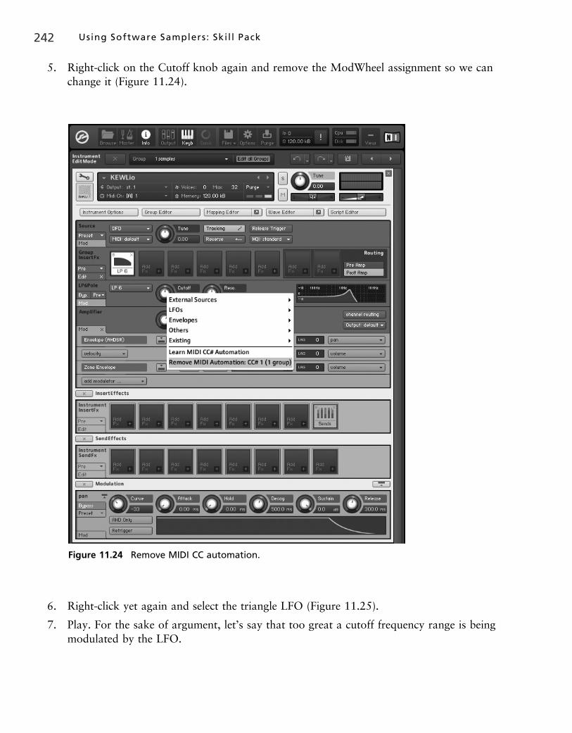
5. Right-click on the Cutoff knob again and remove the ModWheel assignment so we can
change it (Figure 11.24).
6. Right-click yet again and select the triangle LFO (Figure 11.25).
7. Play. For the sake of argument, let’s say that too great a cutoff frequency range is being
modulated by the LFO.
Figure 11.24 Remove MIDI CC automation.
242 Using Software Samplers: Ski l l Pack

8. Lower the slider to 25% as shown in Figure 11.26.
Fixed. This is all too easy; let’s go hog-wild and modulate the Resonance as well.
9. Right-click on the Resonance knob, but this time select Others > 32x step modulator. Set
its frequency to 2.2Hz where circled in Figure 11.26.
Figure 11.25 Triangle LFO.
Chapter 11 Synthesis Parameters 243

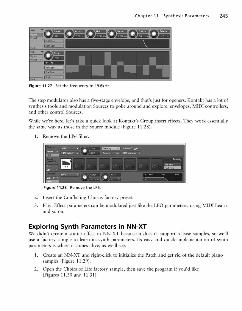
10. Listen. Now speed up the frequency to 19.6Hz. Drag some of the bars representing the
modulation steps around with the mouse to see how this works (Figure 11.27).
Figure 11.26 Step modulator.
244 Using Software Samplers: Ski l l Pack
The step modulator also has a five-stage envelope, and that’s just for openers. Kontakt has a lot of
synthesis tools and modulation Sources to poke around and explore: envelopes, MIDI controllers,
and other control Sources.
While we’re here, let’s take a quick look at Kontakt’s Group insert effects. They work essentially
the same way as those in the Source module (Figure 11.28).
1. Remove the LP6 filter.
2. Insert the Conflicting Chorus factory preset.
3. Play. Effect parameters can be modulated just like the LFO parameters, using MIDI Learn
and so on.
Exploring Synth Parameters in NN-XTWe didn’t create a stutter effect in NN-XT because it doesn’t support release samples, so we’ll
use a factory sample to learn its synth parameters. Its easy and quick implementation of synth
parameters is where it comes alive, as we’ll see.
1. Create an NN-XT and right-click to initialize the Patch and get rid of the default piano
samples (Figure 11.29).
2. Open the Choirs of Life factory sample, then save the program if you’d like
(Figures 11.30 and 11.31).
Figure 11.27 Set the frequency to 19.6kHz.
Figure 11.28 Remove the LP6.
Chapter 11 Synthesis Parameters 245

Figure 11.29 Create and initialize an NN-XT.
Figure 11.30 Open the Choirs of Life.
246 Using Software Samplers: Ski l l Pack

3. The synth parameters apply only to the highlighted samples, so click on the sample in the blue
Mapping area.
4. For convenience, set its loop points at 20–49.2% (Figure 11.32).
This loop clicks, but it doesn’t matter for our purposes—we just want to hear the sound while we
go through the features (Figure 11.33).
Figure 11.33 shows two things:
First, look at the circled area on the NN-XT’s Rack panel. In addition to supporting the Pitch
wheel, the NN-XT allows you to route the mod wheel and one of three External Control choices
to various parameters. Here the default aftertouch is assigned to the External Control wheel.
These onscreen wheels animate in response to incoming MIDI data when you move the physical
controls.
Second, there are six destinations for the wheel and External Control, shown in the Modulation
area. In Figure 11.33 the mouse is hovering over Filter Freq Mod, but all six parameters work
the same. The green M and X buttons enable/disable the parameter for ModWheel and/or
Figure 11.31 Open.
Chapter 11 Synthesis Parameters 247

Figure 11.32 Setting the loop points.
Figure 11.33 Mod control assignments.
248 Using Software Samplers: Ski l l Pack

External Control, in case that’s not obvious, and the knobs determine how much the controls
affect the parameters.
Now let’s set it up so we hear something (Figure 11.34).
1. Enable F. (filter) Freq and F. Res (resonance) for modulation control. Set the filter
(circled in Figure 11.33) Freq to 1kHz and its Resonance to 50%. Make sure the filter is
switched on.
2. Play and wiggle your ModWheel/External Control. Toggle Resonance Control on and off
to hear what it does. Try the different modes, or filter types; we’re going to use HP 12,
which is a 12 dB per octave highpass filter. The mod wheel and/or your External Control
are sweeping the filter and Resonance. We’ll discuss key tracking shortly.
3. Set LFO1’s rate to 2.0kHz and its Filter knob to 22%.
The Filter knob sets the amount it affects the filter, and the Pitch and Level knobs work the
same way. Rate is the speed of the oscillation, and of course it’s a very important parameter.
There are six different waveform choices for the oscillator, and if you switch between them
you’ll see that the pictures show exactly what they sound like.
Figure 11.34 LFO and filter settings.
Chapter 11 Synthesis Parameters 249

4. Now set LFO to Tempo Sync mode and the rate to 1/16 (Figure 11.35).
That’s another way of using the LFO.
5. For fun, assign LFO2, which is simpler than LFO1, to Pan (Figure 11.36).
LFO2 can also control pitch, but instead let’s use the Mod Envelope to do that.
6. In the Mod Envelope area, change its attack to about 2.31 seconds and turn up the Pitch
and Key to Dec (decay) roughly as shown in Figure 11.37.
7. Now listen to what happens to the decay stage of the envelope—i.e., the speed at
which the pitch falls—as you play high and low notes on the keyboard. That’s key
tracking: the pitch falls progressively more slowly as you go up the keyboard. To
Figure 11.35 Tempo sync.
Figure 11.36 LFO2 moving the pan settings around.
250 Using Software Samplers: Ski l l Pack

reverse the effect, simply turn the Key to Decay knob the other way (to 8 o’clock
instead of 4).
8. Finally, you can’t treat any Reason instrument as an entirely separate entity. There are
many ways of modulating the NN-XT’s synth parameters with other devices, such as an
RPG-8 arpeggiator.
9. Create an RPG-8 monophonic arpeggiator. Turn its pattern generator to the right and
click on the steps to create a pattern as shown in Figure 11.38 (the exact pattern isn’t
necessary to demonstrate the point):
Figure 11.37 Mod Envelope settings.
Figure 11.38 The RPG-8 arpeggiator.
Chapter 11 Synthesis Parameters 251

10. Play. Press the Tab key to turn the rack around and see the default connections (Figure 11.39).
All the usual suspects have control input jacks on the NN-XT. Yes, Reason is a lot of fun!
Figure 11.39 The rear of the rack.
252 Using Software Samplers: Ski l l Pack
Related Documents


![Synthesis of gold nanoparticles under highly oxidizing ... · During synthesis, many parameters influence the physico-chemical properties of the obtained gold nanoparticles [18].](https://static.cupdf.com/doc/110x72/5fc5874047abb138300be849/synthesis-of-gold-nanoparticles-under-highly-oxidizing-during-synthesis-many.jpg)