Welcome message from author
This document is posted to help you gain knowledge. Please leave a comment to let me know what you think about it! Share it to your friends and learn new things together.
Transcript


142
saia-pcd.com
132
131
11
Saia® PG5 Core
0 %
100 %
Saia® Software
Wide range with large projects and high complexity
With the Saia® PG5 Project Manager, projects can be managed with just one individual controller or with very large networks.It is used at OEM manufacturers with just one Saia® PCD per machine, and equally well in large properties such as tunnels with over a thousand installed Saia® PCD controllers.
Saia® PG5 Core offers all groups of people involved in ICA and automation technology suitable functions for mastering their tasks reliably and well.As an application engineering tool, users can also implement the most demanding automation projects using graphical application modules in the FUPLA Editor without them having to program in IL, Graftec or Kopla, etc. As a development tool, dedicated control and logic functions, communication drivers and IT functions can be programmed in the Saia® Instruc-tions List. Saia® PG5 offers a large variety of solutions – there is one to suit everyone
1.1 Saia® PG5 Controls Suite: Engineering & programming1.1.1 Saia® PG5 Core – everything you need available at all times
1.1.1.1 Saia® PG5 Core | Basic properties
The Saia® PG5 Project Manager for individual devices just as for large control networks.
The time up to which solution competence is achieved
Software tool with broad user profile – everyone can get used to it quickly
1 day as a basis is sufficient for simple monitoring and control tasks and the adaptation of services
3 additional days in order to implement a primary system, for example
With a learning period of 7 days, special applications can be implemented from automation modules and/or large and distributed properties can be fully automated
Process engineering/ICA technician
Software engineering/ICA
specialist
Software developer and/or automation specialist incl. SCADA/management level
Small projects Large projects
My
expe
rtise
Process engineer Software developer
Saia-Burgess training program 1+3+3
Leve
l of e
xper
tise
The Saia® PG5 Core is a central key element of the Saia® PG5 Controls Suite. This is used to create Saia® PCD projects. The Saia® PG5 Core is included in every software package and is identical throughout.
learning process

143
saia-pcd.com
PCD4 PCD3.M3/5
PCD3.Mx6x
PCD2.M5PCD2
PCD1 PCD1.M2
1990 1994 1996 2005 2007 2010
Einführungsphase3-5 Jahre
Servicephase> 5 Jahre
Produktp�egephase> 10 Jahre
Umstiegsphase
Programm-Kompatible Nachfolgegeneration
18 Jahre < Lebenszyklus Saia® PCD Steuergerät < 25 Jahre
3Sa
ia® S
-Web
tech
nolo
gy
Saia® Software
2Co
mm
unic
atio
n &
In
tera
ctio
n1
Saia
® Sof
twar
e
A standard software – for all device types – now and in the future
Applications can be ported over long periods of time and across all product lines.Virtualization is the key to reusable program code. Java and Microsoft.Net work in the same way. Hardware-de-pendent compilation of applications, e.g. as is normal for soft PLC systems, is obsolete.
Saia® PG5 CoreA tool for all platforms
The control electronics should have the same lifecycle as the systems technol-ogy. It must be possible to adapt and extend at any point in this cycle. The compatibility and free portability of systems/machine software is ensured by an overall product generation of 18-25 years. This only works if engineer-ing software is developed fully in-house and thus relies on “interpreted program code”. This requires more hardware resources but enables the portability of user software across multiple genera-tions of controllers.
Old application programs can be taken over for new Saia® PCD controllers and further processed with the Saia® PG5 Core
Programming tool/software development tool
Java Virtual Machine
Java Bytecode
Saia® Virtual Machine
Saia® Instructions List
Common Language Runtime .NET
Common Intermedia Language
Lifecycle planning of Saia®PCD control devices. Enables maximum profitability of your investment in know-how and systems. Long usage phase without expensive reinvestment and no high service costs.
Changeover phase
Product maintenance phase>10 years
Service phase
>5 years
Introduction phase
3-5 years
CPU hardware level
We supply our devices with a virtual ICA machine. This “machine” always remains the same even if the hardware on it changes. Your application will always run on all device platforms – now and in the future.
18 years < Saia® PCD control device lifecycle < 25 years
Program-compatible subsequent generation
144
saia-pcd.com
André GrossHead of Sales, Switzerland
Patrick MartiDirector of Corporate Sales
Saia-Burgess Controls AG Bahnhofstrasse 18 I CH-3280 Murten I Switzerland T +41 [0]26 672 71 11 I F +41 [0]26 672 74 99 I www.saia-pcd.com
This certificate proves good technical expertise and experience in using Saia® PCD products. It also certifies a serious and reliable working method as a business partner.
2012 | 13
Saia® PCD System Integratoras
for
Certificate
Saia® Software
In principle, any company can apply for the Saia® PG5 license. There are no market-related exclusions as with other providers. The only requirement is the ability to use the products professionally.
With the acquisition of a Saia® PG5 license, a company can register any number of its employees as users. There are no costs per space or per user. However, a company must at least have one proven qualified Saia® PG5 programmer. The qualification can be obtained via training by Saia-Burgess Controls.
There is a special end user license for operators of Saia® PCD automation systems. This includes all Saia® software tools and Saia® application libraries which an external service provider or OEM has used in a system/property to create an automation system. The end user license only applies to the Saia® PCD devices installed at the operator and cannot be used for the creation of automation solutions for third parties.
This certification as a Saia® PCD system integrator shows that a company has proven its ability to implement automation solutions reliably and professionally with Saia® PCD. We recommend that operators, investors and planners take into account the certification when selecting the service provider.
Licensing proceduresThe Saia® PG5 license mechanism offers better flexibility and more simplicity when installing license extensions. The license is distributed as a “user key” file which defines the user permissions for the software applications. A license extension can be quickly distributed by sending the customer an e-mail with a “user key” file or a password. Saia-Burgess Controls AG can create customer-specific user keys using the license manager. The keys can be tailored to any request. It is possible to define the editors or libraries which the customer is permitted to use. The scope, number and size of the projects are irrelevant here.
90-day test license: All Saia® PG5 Controls Suite components can be tested for 90 days free of charge. There are no functional limitations and all the applications developed during the trial period can be used 1:1 in the licensed version.
Saia® PG5 Controls Suite test license
License as a “user key”
Make sure that your systems are created with the correct licenses in order to guarantee the warranty and support as well.
License policy for maximum security, flexibility and independence
145
saia-pcd.com
2005 2007 2008 2010 20112006 200920022001 20122003 2004
PG5 1.3 PG5 1.4 PG5 2.0 PG5 2.1 PG5 1.2 PG5 1.1PG5 1.0
1980 1994 2012
3Sa
ia® S
-Web
tech
nolo
gy
Saia® Software
2Co
mm
unic
atio
n &
In
tera
ctio
n1
Saia
® Sof
twar
e
Software maintenance
We are continually further developing our software in sensible and easy-to-manage innovation steps. The following diagram shows the major version changes over the past 10 years. Known errors are dealt with via patches without a version change. New functions are first tested in beta versions before the sum of all new functions is made official in a major new version. A moderate fee is charged for major version steps with substantial additional functions. This occurs in a cycle of 2–3 years.
The QR code tells you the current progress made in software development. Web Code scen13145
Saia® programming methods existed before the standard
Saia® and IEC EN 61131-3 standard
Saia® PG5 contains the important programming methods but is not compliant with the standard. Why? Saia® programming existed a long time before the standard. By changing to the IEC 61131-3 standard, Saia-Burgess Controls would need to break its promise relating to the portability of application software from one range of devices to another and from one hardware version to the next. We would be devaluing our customers’ investment, and that is something we will not do. It would only result in disadvantages for the user and not any relevant benefits. The IEC 61131-3 standard excludes the item of portability in particular and only covers details on programming.
Milestones in software development and maintenance
IEC 61131-3 standard
Saia® programming software

146
saia-pcd.com
Saia®WebEditor
Saia® PG5S-Edit
Saia® PG5FUPLA
Saia® PG5Graftec
Libs Libs
Libs
Saia® PG5 Symbol Editor
Saia® Software
The Saia® PG5 Core contains the following components:
Project Manager (administers complex installations of networked PCD controllers, including documentation)
Network Configurator (integrated network editors for the configuration of devices and communications networks)
Device Configurator (configuration of hardware parameters on the controller)
Symbol Editor (administers all local, global and network symbols and symbol groups. Auto-allocation largely dispenses with the need for fixed addressing)
On the following pages, the Saia® PG5 Core is presented and the components are explained in more detail.
1.1.1.2 Saia® PG5 Core | Components
Programming methods (integrated programming environ-ments: FUPLA [function block diagram], S-Edit [instruction list IL] and Graftec [sequential function chart] )
Libs (standard libraries which quickly and easily enable all the core functions of the ICA/automation technology)
WebEditor (for WebSCADA functions in every controller)
Saia® PG5 Core at a glance
Saia® PG5Project Manager

147
saia-pcd.com
3Sa
ia® S
-Web
tech
nolo
gy
Saia® Software
2Co
mm
unic
atio
n &
In
tera
ctio
n1
Saia
® Sof
twar
e
Saia® PG5 Project Manager
Project TreeThe layout and structure largely correspond to Windows Explorer. The “Project Tree” window allows direct access to all PCDs used in the project, their settings and the program files and documents that go with them. Program organiza-tion by files (containing one or more program blocks) simplifies the shared use of program files in multiple Saia® PCDs.
The “Program Files” folder may also comprise different data types. It is therefore possible to save all types of program-ming in one folder.
Messages and Error ListDisplays the build log, error and status messages. Errors in the program code are listed here after the build, and can be located directly by clicking.
Window of the Saia® PG5 Project Manager
Network ConfigurationNetwork configuration is used for the configuration of devices and communications networks. Three different configurations generally exist:
1.) Ethernet RIO Network Configurator Smart RIO – PCD3.T665 and PCD3.T666.
2.) BACnet Network Configurator BACnet Configuration Files (*.bnt)
3.) S-Net Network Configurator Profibus-DP Network File (*.dp) Profi-S-IO Network File (*.sio) LON Network File (*.lon)
Network configurator in use – Profi-S-IO Network
The configurations and applications are created, changed and managed in the Saia® PG5 Project Manager. The Saia® PG5 Project Manager is the central linchpin for all work with Saia® PCD controllers.
The following window appears on the left-hand side of the screen as soon as the Saia® PG5 Project Manager is opened. Thanks to desktop docking, there is still enough space on the right-hand side of the screen for further windows.

148
saia-pcd.com Saia® Software
Device Configurator
The hardware and physical functions of the controller are defined in the Device Configurator; e.g. device type, memory modules, communication channels, associated modules and I/Os. The I/O configuration, parameterization and designation, as well as the configuration of the Ethernet protocols, e.g. DNS, DHCP etc., takes place here. The Device Configurator also controls the use of input/output modules in the internal power supply of PCDs and prints the labels which are adhered to the I/O modules.
Selecting Device Configurator in the Saia® PG5 Project Manager
All parameters and modules can be viewed at a glance and printed out as system documentation in the Device Configurator.
Symbol EditorThe Symbol Editor is the heart of the Saia® PG5 Core. It defines and documents all symbols used by the program. The various editors are connected by the Symbol Editor. New symbols used in the program code are taken over directly by the Symbol Editor.
The import/export function allows the reuse of pre-defined I/O lists in electrical diagrams and visualization tools.
Symbols can be grouped together. All the symbols required for a function form one group. This makes it easier to use functions and recognize symbols in the program code, and also gives a clearer overview in the Symbol Editor. Overview of all symbols used in the Symbol Editor

149
saia-pcd.com
3Sa
ia® S
-Web
tech
nolo
gy
Saia® Software
2Co
mm
unic
atio
n &
In
tera
ctio
n1
Saia
® Sof
twar
e
Saia® FUPLA (function block diagram)
FUPLA is Saia®’s own function block diagram editor. It differs in many respects from other graphical programming interfaces: One FUPLA file can contain several program blocks. This means
that one file can encompass an entire machine function. In symbolic programming, each program block is given an individual symbol name. This prevents collisions during the build.
FUPLA blocks are organized into pages. Each page can produce several outputs so that entire functions can be seen at a glance on one page.
Graphical functions (FBoxes) not only have inputs and outputs, but also parameter windows for configuring and online modification.
Saia® FUPLA (function block diagram)
Comment: The Kopla Editor (contact plan) is an integral part of the Saia® PG5 FUPLA Editor. Unlike conventional graphical programming environments, FBoxes and contact plan elements can be freely mixed in one and the same graphic.
Saia® S-Edit (instruction list IL)
Saia® S-Edit (instruction list IL)The editor for the strong instruction set of Saia® PCD. S-Edit combines an editor and online debugger in one interface. The color syntax function detects valid instructions and applies a
color to them. The program code is thus much easier to read and typographical errors are detected immediately.
The “Bookmarks“, “Goto Line”, “Find and Replace” editor functions make it easier to navigate through extensive programs.
The code built can be shown directly in the original code. The function is also used by the integrated debugger.
Complete functions can be copied from the library using drag-and-drop.
Saia® Graftec (sequential function chart)
Saia® Graftec (sequential function chart)Graftec (sequential function chart) is particularly suited to sequential processes. Sequential blocks are a fixed component of the PCD firmware and are processed by it efficiently. Steps and transitions can be programmed in IL and graphi-
cally in FUPLA. In order to ensure a good overview with extensive sequential
processes as well, the division into sub-pages is possible. In online mode, the active transition is permanently displayed. Option to process the code step-by-step in step mode.
Programming methods in the Saia® PG5 Core
150
saia-pcd.com Saia® Software
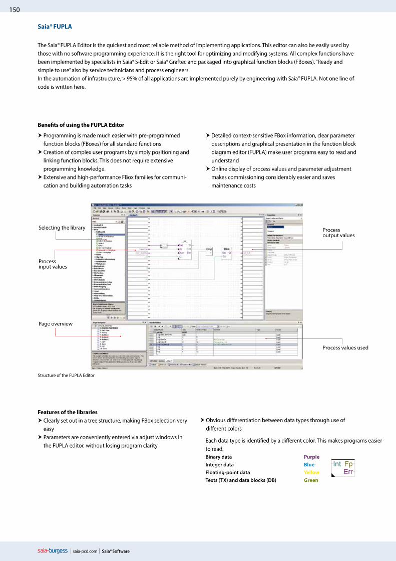
Structure of the FUPLA Editor
The Saia® FUPLA Editor is the quickest and most reliable method of implementing applications. This editor can also be easily used by those with no software programming experience. It is the right tool for optimizing and modifying systems. All complex functions have been implemented by specialists in Saia® S-Edit or Saia® Graftec and packaged into graphical function blocks (FBoxes). “Ready and simple to use” also by service technicians and process engineers.In the automation of infrastructure, > 95% of all applications are implemented purely by engineering with Saia® FUPLA. Not one line of code is written here.
Programming is made much easier with pre-programmed function blocks (FBoxes) for all standard functions
Creation of complex user programs by simply positioning and linking function blocks. This does not require extensive programming knowledge.
Extensive and high-performance FBox families for communi-cation and building automation tasks
Features of the libraries Clearly set out in a tree structure, making FBox selection very
easy Parameters are conveniently entered via adjust windows in
the FUPLA editor, without losing program clarity
Detailed context-sensitive FBox information, clear parameter descriptions and graphical presentation in the function block diagram editor (FUPLA) make user programs easy to read and understand
Online display of process values and parameter adjustment makes commissioning considerably easier and saves maintenance costs
Obvious differentiation between data types through use of different colors
Selecting the library
Processinput values
Page overview
Processoutput values
Process values used
Benefits of using the FUPLA Editor
Saia® FUPLA
Each data type is identified by a different color. This makes programs easier to read.Binary data PurpleInteger data BlueFloating-point data YellowTexts (TX) and data blocks (DB) Green

151
saia-pcd.com
3Sa
ia® S
-Web
tech
nolo
gy
Saia® Software
2Co
mm
unic
atio
n &
In
tera
ctio
n1
Saia
® Sof
twar
e
Clear grouping into families
All FBoxes (function boxes) are grouped into families. This provides a better overview and makes it easier to find individual FBoxes. A distinction is also made between a standard, application and user FBox:
Standard: Shows the FBox libraries of the basic application components
Application: Shows the FBox libraries of the engineering application components
User: Only shows the FBox libraries which the user himself has created
All: Shows all available FBox libraries
Favorite: On this page the user can group together the most frequently used FBoxes (from all libraries). This means that it is no longer necessary to search for FBoxes or to switch between library tabs.
FBoxes in the Saia® PG5 Core
Standard and application FBoxes are already available to the user in the Saia® PG5 Core.
The standard FBox libraries are basic families which offer normal logical and arithmetic operations as well as numerous useful system functions. The “Standard FBox libraries” diagram shows the FBox families available.
In addition to the standard FBoxes, the Saia® PG5 Core contains further FBoxes. These include application FBox libraries which comprise engineering families. These are listed in the “Application FBox libraries” diagram to the right.
The search function (Filter) in the Selector enables a specific FBox to be found quickly.
So that Engineering can access the correct FBoxes, their function and parameters must be known. The online user manual integrated into the PG5 Core is the ideal way to get a quick overview of the relevant FBoxes.Clicking on the FBox makes information such as a brief description of the FBox, an explanation of inputs and outputs, information on the parameter settings and a function description of the FBox accessible to all.
HVAC online user manual
Application FBox libraries
Standard FBox libraries

152
saia-pcd.com Saia® Software
FBox with stretch functionVarious FBoxes can be extended, i.e. the number of input or output connections for the FBox can be defined by moving the mouse vertically. Extendable FBoxes can be pushed back together or stretched further at any time.
FBox without additional functionThere are no additional functionalities for these FBoxes.
Download in run mode These FBoxes can be downloaded during run mode. The PCD does not therefore need to be set to HALT mode first.
Selecting a FBox from the FBox Selector
The functions required to write a program can be selected in the FBox Selector and then added to the FUPLA program using drag-and-drop. This makes it quick and easy to put together a program.
Every FBox in the FBox Selector has a symbol. The meaning of this symbol is explained below:
FBox with adjust functionsSome FBoxes have additional “Adjust Parameters”. These are shown by a black triangle in the bottom left-hand corner. Particular properties of the FBox can be configured using these parameters.
Offline processing of Adjust Parameters Adjust Parameters can be processed offline via the Properties window. The values of the parameters are saved in the FUPLA file. Before the PCD uses the new parameters, the program must be downloaded.
Online processing of Adjust ParametersAdjust Parameters can be processed online via the “View, Adjust Window” instruction, which opens the window for online adjustment whereby both the actual and the processed values are shown. The processed values are written directly to the memory of the PCD and not updated in the FUPLA output file.
A selected FBox is placed into the program by dragging and dropping.
Adjust Window
Adjust Parameters
Drag-and-drop

153
saia-pcd.com
3Sa
ia® S
-Web
tech
nolo
gy
Saia® Software
2Co
mm
unic
atio
n &
In
tera
ctio
n1
Saia
® Sof
twar
e
WebEditor – powerful software tool
The production of web-based visualization and control interfaces is an essential element of engineering effort. Appealing, functionally designed web pages are the public face of the system, supporting operational efficiency and safety. A powerful tool for generating the web pages is therefore crucial.
Saia® WebEditor: Simple, intuitive and efficient
Designing dynamic web pages with a normal HTML editor is laborious and requires specific know-how (in-depth HTML and Java programming knowledge). To ensure that this innovative technology does not remain the preserve of a small circle of specialists, with the Saia® WebEditor, Saia-Burgess provides the user with a simple-to-use software tool for generating web pages. The WebEditor is used to create Java-based web-pages simply and efficiently by placing and parameterizing objects specially tailored to the PCD web server. The use of the Editor is intuitive, and requires no HTML or Java programming knowledge. With optimum integration into the Saia® PG5 Controls Suite and the associated direct access to all symbols, powerful macro management to generate your own reusable macros and many other useful functions for efficient generation of web pages, the engineering costs are significantly reduced compared to other editors.
The tool is based on the automation environment. Areas of use include system visualizations, alarming and trending functions, or just one service page. The full integration into the Saia® PG5 Core, in conjunction with Saia® PCD controllers, guarantees a particularly efficient working method.
The Saia® WebEditor produces appealing web visualizations without any web designer skills.
Start screen for WebEditor 8

154
saia-pcd.com Saia® Software
WebEditor window: Document Outline
WebEditor window: Properties
The WebEditor includes a transparent and adjustable workspace for efficient operation. The workspace essentially comprises the menu/instruction bar, the View Editor (drawing area) and windows. Thanks to docking window technology, the user can freely position and show/hide the windows as he requires.
The most important windows are explained here:
WebEditor window: Solution
The Solution shows the project and file structure. This folder can contain multiple WebEditor projects with various data types. The file types are shown clearly in an orderly tree structure.
The Document Outline window provides an overview of the structure of the current view.
With this window, an element can be selected directly, regardless of its group or level.
WebEditor window: Symbols
WebEditor window: Layers
Symbols are taken over from the configured PG5 project path and updated automati-cally.
To find symbols quickly, the window has a search function.
This window provides an overview of all layers in the view currently open. Layers can be created, moved or deleted. All layers, including the background and foreground view, can be hidden for additional clarity.
In the “Properties” window, the properties and behavior of objects at runtime are quickly and easily configured with just a few clicks.
The window is subdivided into four areas:
General – View settings (depending on conditions)
Actions – Configuration of results (when holding down, when releasing) – Function key
Access – Settings for access control
Other – Element name and comments

155
saia-pcd.com
3Sa
ia® S
-Web
tech
nolo
gy
Saia® Software
2Co
mm
unic
atio
n &
In
tera
ctio
n1
Saia
® Sof
twar
e
All available elements, images and templates are listed in the Library window.Like the Symbols window, a search can be conducted in the Library window.Double-clicking on an element adds it to the open view.
The library in the WebEditor includes the following library groups:
Base Elements Templates for bar graphs, buttons, images, etc.
NoName CheckBox Template
Saia® General View Jumps, URL Jumps, PasswordLogin, etc.
Alarming Objects template for alarming
Trending Objects template for showing trends
Application Library Template objects for HVAC and DDC Suite FBoxes
Icon Gallery Image gallery of Controls AG
WebEditor window: Libraries
Library groups
The macros for the Trending and Alarming library groups are described below.
Macros for displaying alarms and trends
Alarm macro
The system signals are monitored and alarms detected independently of the web browser in the PCD. The actual alarm function is implemented in the firmware (COSinus) of the PCD. Its activation and parameter setting take place with the FUPLA FBox library. The alarms are stored in alarm lists in the non-volatile internal memory of the PCD.
Trend macro
Historical trending is defined as the capture, display and long-term storage of time-stamped system values. Two types of trending are supported – online and offline. With online trending, the client (PC, panel) captures the data and saves it temporarily. The PLC program does not have to be modified. With offline trending, data capture and interim storage take place in the PLC system. This requires special program code (e.g. via FUPLA FBoxes) to be created. The offline trend can either be saved in databases or on the PCD’s file system.
156
saia-pcd.com
Saia®WebEditor
Saia® PG5S-Edit
Saia® PG5FUPLA
Saia® PG5Graftec
Libs Libs
Libs
Saia® PG5 Symbol Editor
Saia® Software
In following example applica-tion, only the Saia® PG5 Core tools shown in color are used.
1.1.1.3 Saia® PG5 Core | Example application
With the Saia® PG5 Core, all types of ICA tasks can be initiated on machines and systems. The graphical application components supplied support the use of the Saia® AutomationServer (web + IT) and calculation/logic functions. The basic functions of the Saia® PG5 Core are shown below using a simple logic.
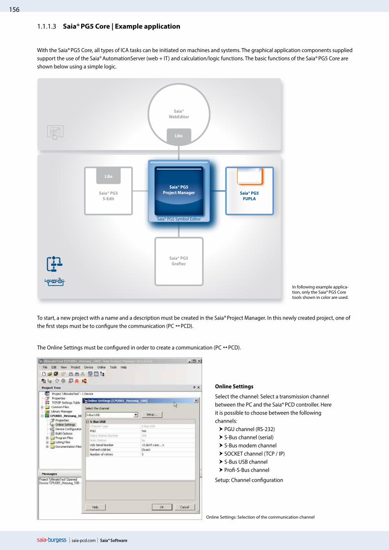
Online Settings: Selection of the communication channel
Online Settings
Select the channel: Select a transmission channel between the PC and the Saia® PCD controller. Here it is possible to choose between the following channels: PGU channel (RS-232) S-Bus channel (serial) S-Bus modem channel SOCKET channel (TCP / IP) S-Bus USB channel Profi-S-Bus channel
Setup: Channel configuration
The Online Settings must be configured in order to create a communication (PC PCD).
To start, a new project with a name and a description must be created in the Saia® Project Manager. In this newly created project, one of the first steps must be to configure the communication (PC PCD).
Saia® PG5Project Manager
157
saia-pcd.com
No 123
No 123
No 123
3Sa
ia® S
-Web
tech
nolo
gy
Saia® Software
2Co
mm
unic
atio
n &
In
tera
ctio
n1
Saia
® Sof
twar
e
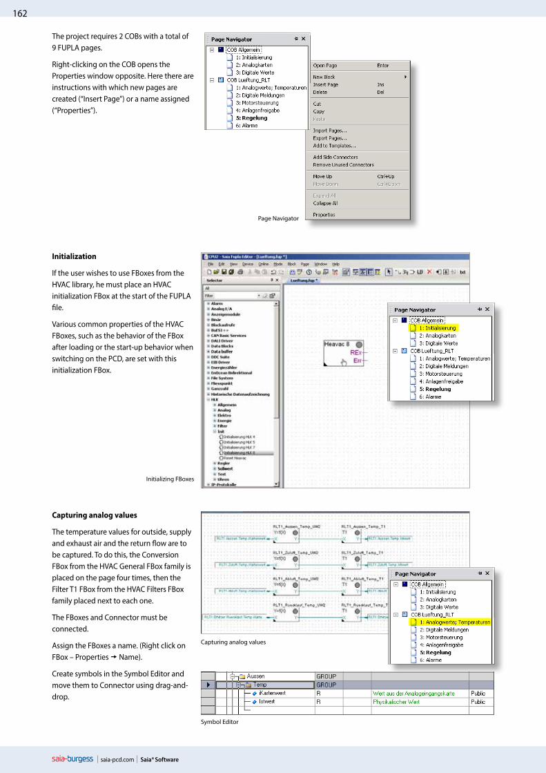
Intuitive display as a function block diagram
User programs can be created from various FBoxes without any extensive knowledge of programming. They can be displayed as desired in the function block diagram editor (FUPLA).
In this example, the performance values of individual energy meters are continually monitored and the maximum and minimum values captured over days, weeks or even years. The voltage and power is compared with variable limit values. If exceeded, a relay output is activated which can be used, e.g., to control a signal lamp or to introduce a peak load cut-out. In addition, an e-mail can be sent to notify a specialist.
Load cut-out
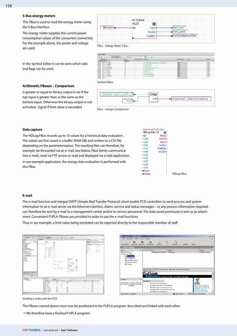
After the hardware settings, a new program file can be created. Right-click on Program Files and then New in the following selection menu.The New File dialog opens. Enter a file name. Make sure that FUPLA Files (*.fup) is selected as the File Type and close the dialog with OK.
� FUPLA file was created, now the user program can be created with FBoxes.
Creating a FUPLA file
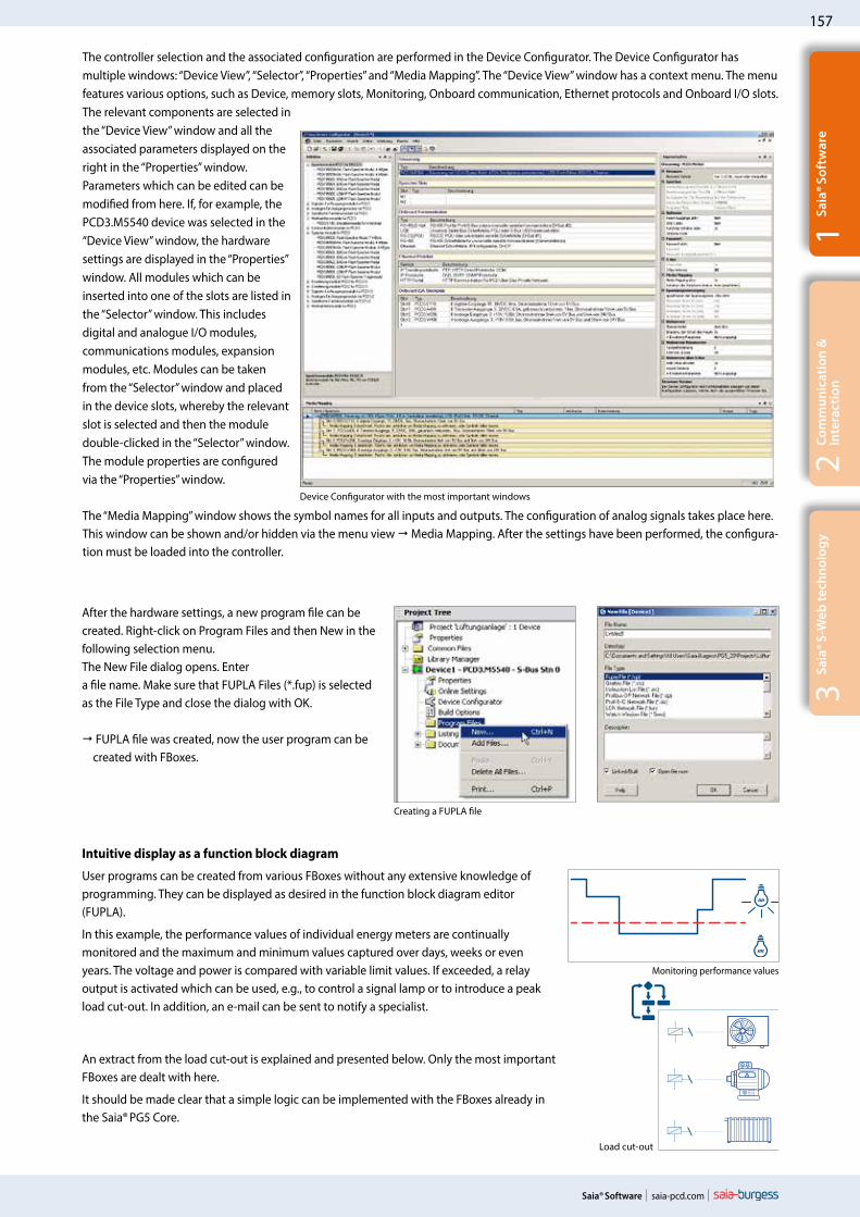
The controller selection and the associated configuration are performed in the Device Configurator. The Device Configurator has multiple windows: “Device View”, “Selector”, “Properties” and “Media Mapping”. The “Device View” window has a context menu. The menu features various options, such as Device, memory slots, Monitoring, Onboard communication, Ethernet protocols and Onboard I/O slots. The relevant components are selected in the “Device View” window and all the associated parameters displayed on the right in the “Properties” window. Parameters which can be edited can be modified from here. If, for example, the PCD3.M5540 device was selected in the “Device View” window, the hardware settings are displayed in the “Properties” window. All modules which can be inserted into one of the slots are listed in the “Selector” window. This includes digital and analogue I/O modules, communications modules, expansion modules, etc. Modules can be taken from the “Selector” window and placed in the device slots, whereby the relevant slot is selected and then the module double-clicked in the “Selector” window. The module properties are configured via the “Properties” window.
The “Media Mapping” window shows the symbol names for all inputs and outputs. The configuration of analog signals takes place here. This window can be shown and/or hidden via the menu view Media Mapping. After the settings have been performed, the configura-tion must be loaded into the controller.
Device Configurator with the most important windows
An extract from the load cut-out is explained and presented below. Only the most important FBoxes are dealt with here.
It should be made clear that a simple logic can be implemented with the FBoxes already in the Saia® PG5 Core.
Monitoring performance values
158
saia-pcd.com Saia® Software
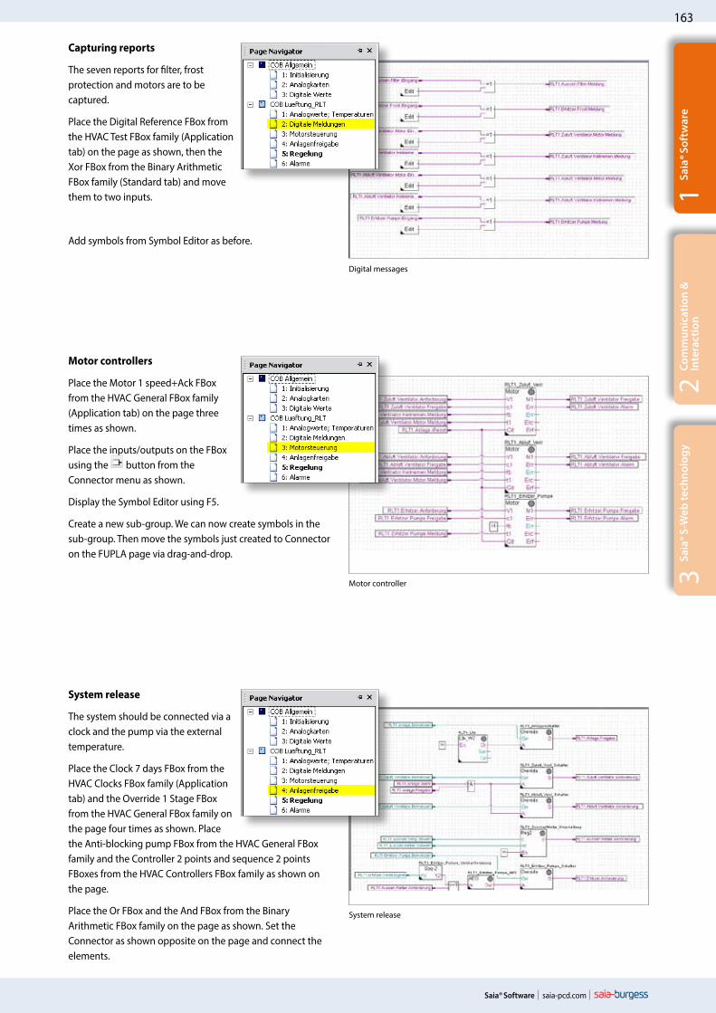
Data capture
The HDLog FBox records up to 10 values for a historical data evaluation. The values are first saved in a buffer (RAM DB) and written to a CSV file depending on the parameterization. The resulting files can therefore, for example, be forwarded via an e-mail (see below, FBox family communica-tion e-mail), read via FTP access or read and displayed via a web application.
In our example application, the energy data evaluation is performed with this FBox.
The e-mail function and integral SMTP (Simple Mail Transfer Protocol) client enable PCD controllers to send process and system information to an e-mail server via the Ethernet interface. Alarm, service and status messages – or any process information required – can therefore be sent by e-mail to a management center and/or to service personnel. The data saved previously is sent as an attach-ment. Convenient FUPLA FBoxes are provided in order to use the e-mail functions.
Thus in our example, a limit value being exceeded can be reported directly to the responsible member of staff.
HDLog FBox
The FBoxes named above must now be positioned in the FUPLA program, described and linked with each other.
We therefore have a finished FUPLA program.
Sending e-mails with the PCD
S-Bus energy meters
This FBox is used to read the energy meter using the S-Bus interface.
The energy meter supplies the current power consumption values of the consumers connected. For the example above, the power and voltage are used.
In the Symbol Editor it can be seen which tabs and flags can be used.
Arithmetic FBoxes – Comparison
Is greater or equal to: Binary output is set if the top input is greater than or the same as the bottom input. Otherwise the binary output is not activated. Signal if limit value is exceeded
Symbol Editor
FBox – Integer Comparison
FBox – Energy Meter S-Bus

159
saia-pcd.com
3Sa
ia® S
-Web
tech
nolo
gy
Saia® Software
2Co
mm
unic
atio
n &
In
tera
ctio
n1
Saia
® Sof
twar
e
As soon as a system function is implemented with FBoxes and has been downloaded to the controller, the current project values can be displayed using “Go online/offline”.
Rebuild All Files
Generating a program (Build)
So that the finished edited program can be read and run by the PCD, it must be generated in the Project Manager via Menu Device Rebuild All Files or using the Rebuild All Files button in the FUPLA Editor or in the Project Manager.
The results of the various program preparation steps (Compiler, Assembler, Linker) are shown in the Messages window.
If the program has been edited correctly, the build function is completed with the message: Build successful. Total errors 0 Total warnings 0
Any errors which have occurred are shown as error messages. By double-clicking on the error message, the error con-cerned can easily be localized in the user program.
Download Program
Transferring the program to the PCD (Download)
The user program is now ready and just needs to be transferred from the PC to the Saia® PCD. This is done using the Download Program button or the Online “Download Program” menu command in the Project Manager.
Should any communications problems arise, the configuration settings (Online Settings) and the PC PCD connection with the USB cable must be checked.
Via the Watch window, it is possible to show selected online data such as the status of inputs/outputs or the content of variables of various FUPLA pages over a specific time. Data can be displayed and changed here.
Data can be entered manually or imported using copy/paste and drag-and-drop. A successful build of the PG5 program automatically updates the symbols with their new address. This also works with the Watch Window open.
FUPLA program – “Go online”
Watch Window
“Go online” causes the current project values to be displayed.
If “Go online” is activated, all binary connections show the current status by means of the line thickness:
Thin “purple” line: Status = 0 Thick “purple” line: Status = 1
By clicking on the line the current value can also be displayed. This also applies to analog values.

160
saia-pcd.com
HVC Library
Saia® Software
Saia® PG5 Core + HVAC library. The visualization is created using the WebEditor.
With the FBoxes included in the Saia® PG5 Core package, the majority of the program functions can already be implemented. In addition, other libraries for special areas of use are available. The HVAC library, for example, has an efficient collection of complex control modules (FBoxes) for the heating, ventilation and air conditioning systems area. These functions simplify the engineering of the technical systems of buildings.
The HVAC library contains the following FBox groups
Analogue: Function blocks for individual scaling of each individual analog input or output
Clocks: Daily program, weekly program, annual program, clock with multiple switching periods in one FBox, national holidays, monthly switch-offs or switching periods one after the other on the same day, as well as FBoxes for reading and writing clock data
Controllers: Two-point controller, three-point controller, boiler loading, P, PZ, PI, PID, P-PI, P-PID controllers, incoming air mixers, controller sequences, mixer sequences
Electric: FBoxes for lighting control, window blind control and step switches
Energy: Energy meters, pulse counters, monthly statement, enthalpy, switching heating on/off, load cut-out
Filters: Filter, limitation, ramp limitation, average of measurement values, dead zone, dead range with delay, zero zone, hysteresis
General: FBoxes for numeric functions, binary functions, alarms, monitoring, motor, blocking and frost protection, process states, switches and the conversion of data types
Init: Initialization of the subfunctions for the HVAC library
Set-Points: Heat curve, heating demand, setpoint device, setpoint ramp, setpoint adjustment
Test: Simulation of values and states
1.1.2.1 HVAC modules
1.1.2 Saia® HVAC modules and use
Saia®WebEditor
Saia® PG5
S-Edit
Saia® PG5
FUPLA
Saia® PG5
Graftec
Libs Libs
Libs
Saia® PG5
Project Manager
Saia® PG5 Symbol Editor
Saia
® H
VAC
lib

161
saia-pcd.com
3Sa
ia® S
-Web
tech
nolo
gy
Saia® Software
2Co
mm
unic
atio
n &
In
tera
ctio
n1
Saia
® Sof
twar
e
Creating a FUPLA file and assigning a name
Example application of the HVAC modules – HVAC system
To start, a new project must be created in the Saia® Project Manager. No adjustment is made on the Device Configurator in this example. This example is merely intended to show the use and application of HVAC FBoxes.
An appropriate name and a description is assigned to the project.
After creating the project, a new program file must be created.
To do this, right-click on Program Files and then New in the following selection menu.
The New File dialog opens. Enter Ventilation as the file name, for example. Make sure that FUPLA Files (*.fup) is selected as the File Type and close the dialog with OK.
Now open the FUPLA program by double-clicking on the file created.
Entering a project name
1.1.2.2 Example application of the HVAC library
The HVAC FBox library is used in order to implement an HVAC system in the following example. The following system should be controlled and regulated by a PCD. The implementation of the FUPLA program is shown clearly on the next few pages in step-by-step instructions.
162
saia-pcd.com Saia® Software
Page Navigator
Initializing FBoxes
Capturing analog values
The project requires 2 COBs with a total of 9 FUPLA pages.
Right-clicking on the COB opens the Properties window opposite. Here there are instructions with which new pages are created (“Insert Page”) or a name assigned (“Properties”).
Initialization
If the user wishes to use FBoxes from the HVAC library, he must place an HVAC initialization FBox at the start of the FUPLA file.
Various common properties of the HVAC FBoxes, such as the behavior of the FBox after loading or the start-up behavior when switching on the PCD, are set with this initialization FBox.
Capturing analog values
The temperature values for outside, supply and exhaust air and the return flow are to be captured. To do this, the Conversion FBox from the HVAC General FBox family is placed on the page four times, then the Filter T1 FBox from the HVAC Filters FBox family placed next to each one.
The FBoxes and Connector must be connected.
Assign the FBoxes a name. (Right click on FBox – Properties Name).
Create symbols in the Symbol Editor and move them to Connector using drag-and-drop.
Symbol Editor
163
saia-pcd.com
3Sa
ia® S
-Web
tech
nolo
gy
Saia® Software
2Co
mm
unic
atio
n &
In
tera
ctio
n1
Saia
® Sof
twar
e
Digital messages
Motor controller
System release
Capturing reports
The seven reports for filter, frost protection and motors are to be captured.
Place the Digital Reference FBox from the HVAC Test FBox family (Application tab) on the page as shown, then the Xor FBox from the Binary Arithmetic FBox family (Standard tab) and move them to two inputs.
Add symbols from Symbol Editor as before.
Motor controllers
Place the Motor 1 speed+Ack FBox from the HVAC General FBox family (Application tab) on the page three times as shown.
Place the inputs/outputs on the FBox using the button from the Connector menu as shown.
Display the Symbol Editor using F5.
Create a new sub-group. We can now create symbols in the sub-group. Then move the symbols just created to Connector on the FUPLA page via drag-and-drop.
System release
The system should be connected via a clock and the pump via the external temperature.
Place the Clock 7 days FBox from the HVAC Clocks FBox family (Application tab) and the Override 1 Stage FBox from the HVAC General FBox family on the page four times as shown. Place the Anti-blocking pump FBox from the HVAC General FBox family and the Controller 2 points and sequence 2 points FBoxes from the HVAC Controllers FBox family as shown on the page.
Place the Or FBox and the And FBox from the Binary Arithmetic FBox family on the page as shown. Set the Connector as shown opposite on the page and connect the elements.

164
saia-pcd.com Saia® Software
Control
Alarms
Analog board
Digital values
Physical inputs and outputs for the test
Position the PCD2.W4 FBox from the HVAC Analog family and move this to two inputs. Position the PCD2.W2 FBox and move this to four outputs. Connect all FBox inputs and outputs with connectours. Enter O 112 in the PCD2.W4 FBox. There must be a space behind O so that the exact output can be identified. The same applies to I,F,R, etc. Enter I 96 in the PCD2.W2 FBox. Move the associated symbols via drag-and-drop from the Symbol Editor to the Connector to the FBoxes.
Position the Override digital FBox from the HVAC General FBox family on the page as shown. Set the connectors and connect all elements as shown. In the Symbol Editor, add the symbol name I0 and 0 as the address.
Return to the symbol name and enter ..7 next to the address I0 and click Enter. The Symbol Editor automatically creates the symbols I1 to I7 with the relevant address for you. Repeat this for the digital outputs O16 ..23 with address 112 to 119. Now move the symbols just created to Connector on the FUPLA page via drag-and-drop.
The symbols are now linked to the inputs and outputs and can be tested.
The FUPLA program shown is a summary of a possible exercise from the basic course on building automation workshop.
Alarm processing
We still need to process messages as alarms. Place the Alarm inhibit 1–10 FBox from the HVAC General FBox family with two inputs and the Alarm FBox on the page as shown. Then position the Or FBox from the Binary Arithmetic FBox family with four inputs, set the Connector and connect all the elements as shown. The FBox with the name VS_01_alarm saves the alarm until it is acknowledged. Since the motor alarms are already saved in the Motor FBox, this can be connected via the Or FBox to the VS_01_alarm_ssm FBox. This FBox is designed to provide a visual and audible alarm notification. The s1 output is reset once acknowledged and the s2 output switches from flashing to being permanently on. Only once the alarm is cleared does s2 also go out.
Control
The system should receive a supply/exhaust air temperature cascade as a control.
Place the W/Ambient temperature FBox from the HVAC Set-Points FBox family and the Controller PI and Sequence Master HC FBox from the HVAC Controllers FBox family on the page as shown. Place the Maximum FBox from the Integer Arithmetics FBox family on the page as shown. Connect the elements. Now a few basic settings still need to be made in the FBoxes. The Properties window opens by clicking on the FBox. All values are experience values which can be used to control temperature as a basis for adjustment. Obviously these values must be adjusted according to the control behavior during operation.

165
saia-pcd.com
Saia®WebEditor
Saia® PG5S-Edit
Saia® PG5FUPLA
Saia® PG5Graftec
Libs Libs
Libs
Saia® PG5 Symbol Editor
Saia
® D
DC
Suite
3Sa
ia® S
-Web
tech
nolo
gy
Saia® Software
2Co
mm
unic
atio
n &
In
tera
ctio
n1
Saia
® Sof
twar
e
Saia® PG5 Core + DDC Suite library
Using the Saia® PG5 DDC Suite library and templates makes the creation of HVAC applications even simpler. Complex program structures and application elements such as complete pump controllers, incl. hour meters or entire control tasks for ventilation systems are grouped together as templates in individual function boxes and optimally add to the current HVAC library. This means that projects can be implemented efficiently.
Complete pump control with HVAC library
Complete pump control with DDC Suite library
We can already see a number of benefits when comparing the two FUPLA pages (HVAC and DDC Suite). It is easier to read and understand the FUPLA program – fewer FBoxes and links on one page. Arranged clearly and transparently – easier to handle, e.g. for new colleagues in the developer or service team Easy to maintain
1.1.3 Increasing engineering efficiency through Saia® installation templates1.1.3.1 DDC Suite
Saia® PG5Project Manager
Saia
® H
VAC
Lib

166
saia-pcd.com Saia® Software
The following FBox families are available to the DDC Suite library user:
DDC Alarming: Fault modules for motors, fire protection and various components
DDC Analogue values: FBoxes for capturing measurement values
DDC Controller: Control modules for components such as cooler, heat recovery system and heater
DDC Controls: Triggering of motors, pumps, flaps and drives
DDC General: General FBoxes such as manual information, media access
DDC Initialisation: Modules which must be inserted once into a FUPLA and which provide basic functions.
DDC Set-Points: Conversions, setpoints
DDC Systems and Clocks: Clocks, systems and aggregate switches
This FBox library with highly integrated FBoxes uses individual data points and creates groups and symbols automatically.
1. Integrated trending (offline history)If, in addition to the actual control and regulation of a system, data is also to be recorded, this is easily done using the Saia® DDC Suite. By defining the memory size in the object parameter window, the data capture for trending can be initiated. When the automa-tion system is running, the data is now continually saved in the Saia® PCD and is available for evaluation. In addition, a document (.txt) containing all parameterized historical data is saved in the Saia® Project Manager. A list of the trend settings can be seen in this file. There is one entry for each trend with all the details.
DDC Suite library
The unique features of the DDC suite are divided into 5 points:
Trending
Object parameter window

167
saia-pcd.com
3Sa
ia® S
-Web
tech
nolo
gy
Saia® Software
2Co
mm
unic
atio
n &
In
tera
ctio
n1
Saia
® Sof
twar
e
2. Integrated alarmingThe principle of the trend function also applies to alarm functions. By defining the alarm number in the object parameter window, the alarms are listed in a CSV file with numbers and text.
With Version 2.5 of the DDC Suite, the system identification key can be created completely freely directly from FUPLA. The aim is to create the system identification key for the S-Web alarm texts and BACnet® completely freely according to the specifications from the FUPLA program. The system identifi-cation key can have up to 12 levels. The general section (levels 1-10) is specified conveniently from a central FBox. This FBox can be positioned multiple times. Within the FBox it can be selected what the key is to be used for. Thus, for example, various system identification keys can be created for S-Web alarming, the BACnet® Object Names and the BACnet® Description. If on certain FUPLA pages, for example for various systems, other levels are used, a further FBox is simply placed on the page. These FBoxes can also be used as often as desired and the changes to the system identification key are valid for the next FBox of this type. Thus a different name key can be used for each system.
3. Automatic generation of the BACnet® configurationFor BACnet® projects, the BACnet® object list is created automatically, which saves a great deal of error-prone manual work. The automatic generation of the BACnet® objects is the main reason why so many customers use the DDC Suite. In building automation, it is normal for all systems to map relevant hardware and software data points to BACnet® objects. This may mean that multiple data points are used in a BACnet® object. Thus, for example, a binary output could receive exactly the same return message and be monitored via intrinsic alarming. The control templates for the DDC Suite already contain all BACnet® definitions which can be activated by clicking, thus BACnet® originates at the click of a button.
4. Automatic documentationThe engineering documentation can be created quickly at the click of a button. The documentation on all DDC Suite FBoxes is created as an HTML file. This file contains a general description with all parameters and settings. The documentation can be saved in the PCD and, for example, be used for viewing via the web. It is, however, also possible to post-edit the documentation using a text processing tool and to add images from the SCADA/web application.
Alarming
BACnet configurator
HTML document

168
saia-pcd.com Saia® Software
5. Templates for FUPLA, WebEditor and Visi.Plus The Saia® DDC Suite largely comprises a highly integrated FBox library which is supplemented by a growing number of ready-made, tested and ready-to-use FUPLA pages which fully map the typical parts of the system in terms of function. The Saia® DDC Suite also provides the operating and visualization function for each FBox. Operation and visualization using the web browser or Visi.Plus is already integrated and ready for use.
FUPLA templatesIn order to reduce the system programming time, entire applications (heating circuit, water heating, ventilation systems, etc.), includ-ing the calendar and control tasks, are fully integrated for free selection. Some suggestions for control settings and for system control can thus be freely added, changed or integrated.
Visi.Plus templatesWhen importing data from FUPLA to Visi.Plus, FBoxes are identified and then handled by the Visi.Plus database as FBoxes. Not only are the data points imported, but the alarms and historical trends are automatically created upon import. In addition, the Visi.Plus user is provided with the same template objects as in WebEditor.
WebEditor templates The DDC Suite is also accompanied by template objects for S-Web applications. Graphical objects and control objects are available for each FBox. There are also S-Web system templates for predefined systems.
All official macros can be found in the “Library” WebEditor window.
Template: Ventilation system
System schematic

169
saia-pcd.com
3Sa
ia® S
-Web
tech
nolo
gy
Saia® Software
2Co
mm
unic
atio
n &
In
tera
ctio
n1
Saia
® Sof
twar
e
Adjusting the template pagesMost functions, settings and parameters can be set online. In the event of a function change, this means that the program is not normally recompiled and loaded into the controller. Thus, for example, the setpoint adjuster can easily be disabled if required the operator so desires or if the setpoint is to be used without any summer compensation. This reduces the commissioning time.
The template pages can also be adjusted with further FBoxes if required.
FUPLA Selector
1.1.3.2 Example application of the DDC Suite
In the previous example it was made clear how quickly and easily the implementation of an HVAC system can be performed with the correct engineering tool. The engineering time can, however, be further reduced using the DDC Suite.
Engineering startAfter the hardware settings (Device Configurator), a new program file (FUPLA file) is created. The implementation of a system can now begin. Various templates are provided so that the creation of a new HVAC system does not have to start again from the very beginning.After clicking on the “Template” symbol in the FUPLA Selector, the available templates are listed.
Selecting templates: In this example, the template AirCond_T1 is used.
The AirCond_T1 template contains the FBoxes and links visible here.
Generating a programAs soon as the program is generated information is created automatically. BACnet configuration has been created (BACnet.bnt) Alarms with numbers and text are listed in a CSV file (DDC_Alarming.CSV) Documentation as an HTML file with settings is created (DDC_Dokumentation.htm) List of all parameterized historical data (DDC_HDLog.txt)
VisualizationIn the WebEditor, the template must be linked to the FUPLA page with just a few clicks.
Unlike the standard HVAC FBoxes, the symbolic parameter assignments in the FBoxes are not defined as arrays: Each individual parameter can and/or must be given its own symbolic assign-ment if a connection to a display or a building automation system is required. This assignment is no longer needed for the DDC Suite library since all parameters already contain symbolic assign-ments. Thus the assignment to an image in the WebEditor is very quick.
Project Tree with Program Files
Linking symbols

170
saia-pcd.com
Saia®WebEditor
Saia® PG5S-Edit
Saia® PG5FUPLA
Saia® PG5Graftec
Libs Libs
Libs
Saia® PG5 Symbol Editor
Saia
® D
DC
Suite
My
Suite
Saia® Software
1.1.4 Saia® PG5 Controls Suite
1.1.4.1 My Controls Suite
In addition to the templates which can be easily created and reused, it is also possible to create your own FBoxes and/or your own FBox library (My FBox Lib). The FBox Builder, which can be found in the Saia® PG5 Core, is used for this.
Creating templates
Using template pages
The use of predefined FBoxes and/or templates is not mandatory. Saia® PG5 Core enables individual templates to be created and even offers the opportunity to define these templates with purely graphical engineering, without any IL programming.
Creating templates
Using templates significantly simplifies processes and reduces engineering time. In order to implement projects more efficiently, it is not only possible to use existing templates, but also user-specific engineering projects as templates. Users who have built their standard FUPLA pages can export and save them as .fxp files (a .fxp file includes any number of FUPLA pages). To reuse the pages, the .fxp files must be located and then imported.
Saia® PG5 Core – My Controls Suite
Saia® PG5Project Manager
Saia
® H
VAC
Lib
171
saia-pcd.com
Saia® PG5S-Edit
Saia® PG5FUPLA
Saia® FBox-Builder
Saia® PG5Graftec
Libs LibsMy
FBoxLibs
Saia® PG5 Symbol Editor
Saia® PG5S-Edit
Saia® PG5FUPLA
Saia® PG5Graftec
Libs LibsMy
FBoxLibs
Saia® PG5 Symbol Editor
Saia® FBox-Builder
3Sa
ia® S
-Web
tech
nolo
gy
Saia® Software
2Co
mm
unic
atio
n &
In
tera
ctio
n1
Saia
® Sof
twar
e
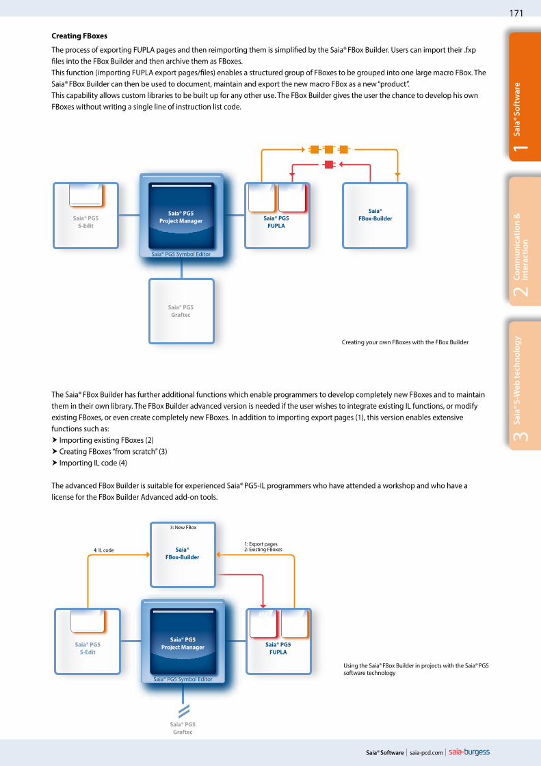
The Saia® FBox Builder has further additional functions which enable programmers to develop completely new FBoxes and to maintain them in their own library. The FBox Builder advanced version is needed if the user wishes to integrate existing IL functions, or modify existing FBoxes, or even create completely new FBoxes. In addition to importing export pages (1), this version enables extensive functions such as: Importing existing FBoxes (2) Creating FBoxes “from scratch” (3) Importing IL code (4)
The advanced FBox Builder is suitable for experienced Saia® PG5-IL programmers who have attended a workshop and who have a license for the FBox Builder Advanced add-on tools.
Using the Saia® FBox Builder in projects with the Saia® PG5 software technology
Creating FBoxes
The process of exporting FUPLA pages and then reimporting them is simplified by the Saia® FBox Builder. Users can import their .fxp files into the FBox Builder and then archive them as FBoxes. This function (importing FUPLA export pages/files) enables a structured group of FBoxes to be grouped into one large macro FBox. The Saia® FBox Builder can then be used to document, maintain and export the new macro FBox as a new “product”. This capability allows custom libraries to be built up for any other use. The FBox Builder gives the user the chance to develop his own FBoxes without writing a single line of instruction list code.
Creating your own FBoxes with the FBox Builder
Saia® PG5Project Manager
Saia® PG5Project Manager
4: IL code1: Export pages2: Existing FBoxes
3: New FBox
172
saia-pcd.com Saia® Software
Saia® WebEditor – Web visualization for automation
The Saia® WebEditor produces appealing web visualizations without any web designer skills.The tool is based on the automation environment. Areas of use include system/machine visualizations, alarming and trending functions, or one service page. The full integration into the Saia® PG5 Core, in conjunction with Saia® PCD controllers, guarantees a particularly efficient working method.
A stand-alone variant is also provided for applications independent of Saia® PCD controllers.
Stand-alone variant
The WebEditor is independent software which can be used without the Saia® PG5 Core.
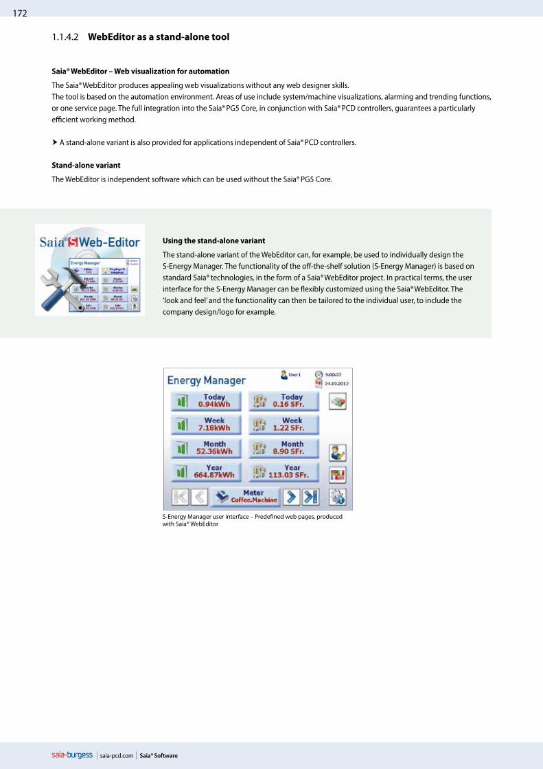
Using the stand-alone variant
The stand-alone variant of the WebEditor can, for example, be used to individually design the S-Energy Manager. The functionality of the off-the-shelf solution (S-Energy Manager) is based on standard Saia® technologies, in the form of a Saia® WebEditor project. In practical terms, the user interface for the S-Energy Manager can be flexibly customized using the Saia® WebEditor. The ‘look and feel’ and the functionality can then be tailored to the individual user, to include the company design/logo for example.
S-Energy Manager user interface – Predefined web pages, produced with Saia® WebEditor
1.1.4.2 WebEditor as a stand-alone tool

173
saia-pcd.com
3Sa
ia® S
-Web
tech
nolo
gy
Saia® Software
2Co
mm
unic
atio
n &
In
tera
ctio
n1
Saia
® Sof
twar
e
The combined platform of the Saia® software is the Saia® PG5 Controls Suite DVD. This includes software tools for project configuration, engineering, programming and service. The DVD also includes application components with which you can increase your productivity when using Saia® PCD products. You will also find a wide range of system software on the Saia® PG5 Controls Suite DVD. This predomi-nantly involves driver software which simply and reliably ensures the integration into a system environment.
Saia® PG5 Controls Suite contains everything you need for automation
PC tools
Saia® PG5 Core Project Manager Application Programming Application Engineering Network Management Service
Saia®WebEditorTool for creating web pages for the Saia®PCD WebServer
Saia®Visi.PlusVisualization and management software for applications in infrastructure automation
Saia® HMI EditorTool for Saia® PCD Text Panels
Saia® FBox BuilderTool for creating and managing Saia® FUPLA FBoxes
Saia®S-Service Online ToolsDownloading PG5 programs without installing the Saia® PG5 Core
Application components
Standard FBoxesProgram modules for Saia® FUPLA, the graphical engineering tool Arithmetic and logical FBoxes Analog FBoxes Communication FBoxes
Application FBoxesProgram modules for Saia® FUPLA, the graphical engineering tool.FBoxes: Alarm, DALI, DDC Suite, EIB, Energy Meter, EnOcean, Historical Data Capture, HVAC, Blinds/Lighting, JCI N2-Bus, E-Mail Communication, LON, Modbus, Modem, MP-Bus, Room Controller
IL librariesFunction blocks for counter modules, drive modules and analog modules can be integrated into IL programs
List of tools in the Saia® Controls Suite
Application software
Saia® Web-ConnectThe PC program enables access to the PCD WebServer via any communication interface (RS 232, RS 485, Profibus, Ethernet, etc.)
SD Flash ExplorerWith SD Flash Explorer, the content of the Saia® file system can be extracted to the PC.
Saia® .Net SuiteSimple integration of Saia® automation components into Windows applications
All on one DVD.
Application software for Saia® PCD projects can be run on PCs, panels, PDAs, etc.
Application compo-nents for Saia® PCD projects
PC tools for creating Saia® PCD projects
1.1.4.3 Overview of the tools and license packages

174
saia-pcd.com
Saia® PG5Saia® PG5
S-EditSaia® PG5
FUPLA
Saia® PG5Graftec
Libs Libs
Saia® PG5 Symbol Editor
Saia® WebEditor
Saia® Visi.Plus
Libs
LibsLi
bs
Saia® Software
Saia® PG5 options – Add-on libraries: Tool is separated from libs. The FBox libraries can also be ordered.
License packagesWe have defined three packages as a global standard out of the large variety of possible software combinations with the Saia® PG5 Controls Suite. The training programs, online training and documentation are based on these.
Saia® PG5 Core PackageWith this package, all types of ICA tasks can be initiated on machines and systems. The graphical application components supplied support the use of the Saia®AutomationServer (Web + IT) and simple calculation and logic functions.
Saia® PG5 HVAC PackageIn addition to the Saia® PG5 Core Package, further collections of graphical control modules (FBoxes) are included which are oriented to the needs of HVAC primary systems. Template pages can be created from the Saia® basic collection of HVAC ICA modules which map any kind of system configuration.
Saia® PG5 Extended PackageIn addition to the Saia® PG5 HVAC Package, highly integrated graphical modules (DDC Suite) are included as well as a collection of templates which map the current system design of the HVAC technology.
For details see order information
The three standard packages can only be differentiated by the licensed application components (FBoxes, templates); the Saia® PG5 Core always remains identical.
Scope and content of the Saia® PG5 packages
Saia® PG5Project Manager

175
saia-pcd.com
3Sa
ia® S
-Web
tech
nolo
gy
Saia® Software
2Co
mm
unic
atio
n &
In
tera
ctio
n1
Saia
® Sof
twar
e
Saia® PG5 programming tool
PG5 – Demo version with all functions. Runtime limited to 90 days PG5 – Demo
Saia® PG5 Core Package1)
Programming software with editors (IL, FUPLA, Graftec), network configurators,standard libraries (Analog, Communication, Arithmetic & Logic), application libraries (Alarming, Blinds-Lighting, E-Mail, Trending [HDLog], Energy Meter, DALI, Modbus, EIB, EnOcean, JCI N2-Bus), WebEditor and FBox Builder (basic version)
PG5 – Core Package
Saia® PG5 HVAC Package1)
Same as Saia® PG5 Core Package and associated libraries (HVAC, Belimo MP-Bus, LonWorks, Room controllers and Modem), BACnet
PG5 – HVAC Package
Saia® PG5 Extended Package1)
Same as Saia® PG5 HVAC Package and associated DDC Suite libraryPG5 – Extended Package
Software upgradeUpgrade – according to customer’s key
PG5 – Upgrade
End customer license for Saia® PG5End customer license for PG5. The customer is supported by the requisitioner (according to customer’s key)
PG5 – End-User License
Saia® PG5 options – Add-on libraries
PG5 – Modem LibraryModem base library incl. Data Buffer, DTMF, Pager & SMS libraries
PG5 – Modem
PG5 – HVAC LibraryHVAC Library for building automation
PG5 – HVAC
PG5 – DDC Suite LibraryDDC Suite Library for building automation (available in German/English/French)
PG5 – DDC Suite
PG5 – Belimo MP-Bus Library Library for Belimo MP-Bus
PG5 – MP-Bus
PG5 – Room Controller1)Library for room control units
PG5 – Room Controller
PG5 – Lon1)
Library for LonWorks®PG5 – Lon
Saia® PG5 options – Add-on tools
PG5 – WebEditorSoftware package for Saia® WebEditor as a stand-alone tool
PG5 – WebEditor
PG5 – FBox Builder (“advanced version”) Software package for Saia® FBox Builder. IL knowledge needed and 1 day’s training included
PG5 – FBox Builder
Order information| Saia® PG5 Controls Suite
1) Available from April 1, 2013Scope and content of the Saia® PG5 packages
176
saia-pcd.com
Visi.Plus
N
W
S
E
NW
SW
SE
NE
EN
E
NW
NE
Saia® Software
1.2 Application software for Windows PCs1.2.1 Saia® Visi.Plus | Classic control/management system
Software package for visualization and management tasks – for reliable, efficient and cost-effective project implementation in connection with Saia® automation systems and DDC Suite.
Main characteristics of Saia®Visi.Plus
Optimally integrated and adjusted to Saia® PG5 and Saia® PCD, successfully used worldwide since 2001
Reduced commissioning and maintenance costs, due to clear handling and freely available Engineering Edition
The integrated web server allows all process data to be displayed with a web browser at no additional cost
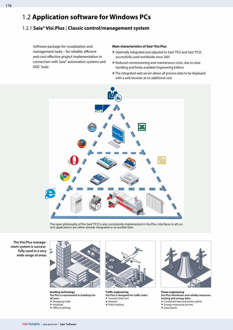
The open philosophy of the Saia® PCD is also consistently implemented in Visi.Plus. Interfaces to all cur-rent applications are either already integrated or accessible later.
Building technologyVisi.Plus is represented in buildings for all uses: Shopping malls Hospitals Office buildings
Traffic engineeringVisi.Plus is designed for traffic tasks: Tunnels (train/car) Airports Point heating
Power engineeringVisi.Plus distributes and reliably measures heating and energy data: Combined heat and power plants Energy measuring servers Solar plants
The Visi.Plus manage-ment system is success-
fully used in a very wide range of areas

177
saia-pcd.com
3Sa
ia® S
-Web
tech
nolo
gy
Saia® Software
2Co
mm
unic
atio
n &
In
tera
ctio
n1
Saia
® Sof
twar
e
Visi.Plus
Visi.Plus
Management level
Automation level
Field level
Saia® Visi.Plus provides support at the start of the project and performs valuable services which save time and money. The Engineering Edition is included in Saia PG5 Core and can be used for commissioning and optimization. The runtime management system is activated by the acquisition of a license, all operating images and settings are taken over automatically. Thanks to the DDC Suite and a few mouse clicks, the following functions are available immediately:
Engineering Edition – Saia® Visi.Plus
Alarming Alarm list incl. history Forwarding via e-mail or SMS Control for end customers
Trends Recording closed loops Controlling optimizations Confirmation for end customers
Control panels Complete system overview Simple configuration Optimization through visualization
Web Remote access possible immediately Support according to putting into operation Control by planner/end customer
Benefits of Visi.Plus to assist with commissioning/optimization
Immediate overview of trend and alarming data Development environment included in Saia® PG5 and fully functional Easy control of all parameters and regulation systems
A small step for the integrator – huge benefits for the operator
Visi.Plus as a tool for commissioning and optimization
Visi.Plus as a complete management system
Benefits of Visi.Plus as a management system
Open structure for connecting to standard systems (OPC, BACnet, Modbus, SQL, MS Office)
Scalable architecture, for price optimization across a broad spectrum of use
Optimally integrated and dedicated to Saia® PG5 and Saia® PCD
Runtime license
Management level
Automation level
Field level

178
saia-pcd.com Saia® Software
Visualization and graphical editor
All relevant parts of the system can be presented to the user in the most appropriate way with the powerful graphical editor. The use of vector and bitmap graphics allows both overviews and detailed information to be displayed. The graphical editor also helps with visualization in runtime mode. This means that the user can switch to editor mode at any time (via password) to make corrections and changes.
Operator programs
Web ServerAll graphics pages generated are automatically saved as web pages. All generated pages and functions can be displayed and operated using a browser, by activating the Visi.Plus web server.
LogThis module logs and stores all events in a file at user level. The log viewer, with its integral filter functions, allows all important events to be displayed in the most appropriate way to the user.
Alarm management Alarm management is an essential constituent of any building management system. With Saia®Visi.Plus it is possible, by observing limit values, to display all relevant data points for the user in a plain-text alarm window. Two separate alarm lists provide a better overview. The first gives an overview of all alarms; the second enables all current alarms to be examined.
Trend display With this module you can, for example, receive a monthly summary energy balance sheet for all consumers in a building. Whether you have to monitor the consumption of water, electricity or heat, this trend analysis provides you with the necessary overview to enable suitable measures to be initiated.
179
saia-pcd.com
3Sa
ia® S
-Web
tech
nolo
gy
Saia® Software
2Co
mm
unic
atio
n &
In
tera
ctio
n1
Saia
® Sof
twar
e
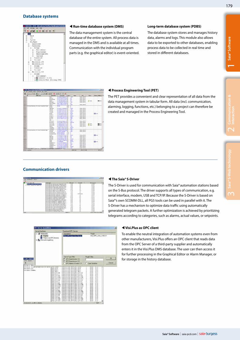
Run-time database system (DMS)
The data management system is the central database of the entire system. All process data is managed in the DMS and is available at all times. Communication with the individual program parts (e.g. the graphical editor) is event-oriented.
Long-term database system (PDBS)
The database system stores and manages history data, alarms and logs. This module also allows data to be exported to other databases, enabling process data to be collected in real time and stored in different databases.
Process Engineering Tool (PET)
The PET provides a convenient and clear representation of all data from the data management system in tabular form. All data (incl. communication, alarming, logging, functions, etc.) belonging to a project can therefore be created and managed in the Process Engineering Tool.
Database systems
The Saia® S-Driver
The S-Driver is used for communication with Saia® automation stations based on the S-Bus protocol. The driver supports all types of communication, e.g. serial interface, modem, USB and TCP/IP. Because the S-Driver is based on Saia®’s own SCOMM-DLL, all PG5 tools can be used in parallel with it. The S-Driver has a mechanism to optimize data traffic using automatically generated telegram packets. A further optimization is achieved by prioritizing telegrams according to categories, such as alarms, actual values, or setpoints.
Visi.Plus as OPC client
To enable the neutral integration of automation systems even from other manufacturers, Visi.Plus offers an OPC client that reads data from the OPC Server of a third-party supplier and automatically enters it in the Visi.Plus DMS database. The user can then access it for further processing in the Graphical Editor or Alarm Manager, or for storage in the history database.
Communication drivers

180
saia-pcd.com Saia® Software
Analysis of trend data (PChart)If the user wishes to display or export trends, however they have been compiled, PChart is the tool to use. The trend data can be displayed in a variety of colors and different scales.
MALM ESPA 4.4.4 With this module, alarms can be forwarded to telecommunica-tions systems with an ESPA 4.4.4 interface (serial, type RS-232), to be output to the display of a telephone within the local telephone network.
pSMS With a GSM-compatible modem (not included), SMS messages can be received and their content assessed according to a specification (e.g. to acknowledge alarms or modify values).
SNMP ManagerDriver to monitor network components that provide SNMP services, such as routers or controllers. The values polled (depending on parameters set) are integrated into the Visi.Plus database, where they can be processed further (e.g. for history data or alarms).
Add-on programs
MALM Voice When an alarm occurs, a voicemail message (sound file in WAV format) can be played back via telephone. The person called can then use the same call to acknowledge the alarm by entering a sequence of numbers (requires a DTMF-enabled telephone).
ESPA 4.4.4 (RCV) Messages transmitted by telecommunications systems with an ESPA 4.4.4 interface (serial, type RS-232) can be implemented as alarm messages by Visi.Plus and used for further processing and logging.
pCalc Calculations for energy analysis and system monitoring, up to 1,000 formulas with 16 variables each.
Mobile Alarm (MALM) Remote alarms via email/SMS.When monitoring technical building installations it is necessary to guarantee that, in the absence of service personnel, fault messages are forwarded quickly and safely. Direct diagnosis of the fault message is also possible via remote dial-in, thus avoiding unnecessary journeys by service personnel. The alarm is sent via SMS or email.
System requirementsVisi.Plus requires the following as a minimum:
Windows 2000, Windows XP, Windows XP Embedded, Windows Vista, Windows 7 (32 / 64-bit versions)
Windows Server 2003, Windows Server 2008 (32 / 64-bit versions)
Pentium 1 GHz PC 512 MB RAM (the higher the number of DMS data points, the
more memory that is required) Hard disk with at least 60 MB free memory (for the installation) CD-ROM drive (poss. external data backup (CD writer))
181
saia-pcd.com
3Sa
ia® S
-Web
tech
nolo
gy
Saia® Software
2Co
mm
unic
atio
n &
In
tera
ctio
n1
Saia
® Sof
twar
e
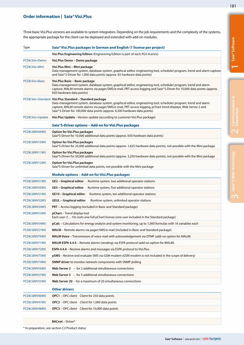
Type Saia® Visi.Plus packages in German and English (1 license per project)
Visi.Plus Engineering Edition (Engineering Edition is part of each PG5 licence)
PCD8.Visi+Demo Visi.Plus Demo – Demo package
PCD8.Visi+Mini Visi.Plus Mini – Mini package Data management system, database system, graphical editor, engineering tool, scheduler program, trend and alarm capture and Saia® S-Driver for 1,000 data points (approx. 65 hardware data points)
PCD8.Visi+Basic Visi.Plus Basic – Basic package Data management system, database system, graphical editor, engineering tool, scheduler program, trend and alarm capture, MALM remote alarms via pager/SMS/e-mail, PRT access logging and Saia® S-Driver for 10,000 data points (approx. 650 hardware data points)
PCD8.Visi+Standard Visi.Plus Standard – Standard package Data management system, database system, graphical editor, engineering tool, scheduler program, trend and alarm capture, MALM remote alarms via pager/SMS/e-mail, PRT access logging, pChart trend displays, Web Server 2 and Saia® S-Driver for 100,000 data points (approx. 6,500 hardware data points)
PCD8.Visi+Update Visi.Plus Update – Version update (according to customer Visi.Plus package)
Saia®S-Driver options – Add-on for Visi.Plus packages
PCD8.S89V09M5 Option for Visi.Plus packages Saia®S-Driver for 10,000 additional data points (approx. 650 hardware data points)
PCD8.S89V10M5 Option for Visi.Plus packages Saia®S-Driver for 25,000 additional data points (approx. 1,625 hardware data points), not possible with the Mini package
PCD8.S89V11M5 Option for Visi.Plus packages Saia®S-Driver for 50,000 additional data points (approx. 3,250 hardware data points), not possible with the Mini package
PCD8.S89V12M5 Option for Visi.Plus packages Saia®S-Driver for unlimited data points, not possible with the Mini package
Module options – Add-on for Visi.Plus packages
PCD8.S89V21M5 GE2 – Graphical editor Runtime system, two additional operator stations
PCD8.S89V50M5 GE5 – Graphical editor Runtime system, five additional operator stations
PCD8.S89V51M5 GE10 – Graphical editor Runtime system, ten additional operator stations
PCD8.S89V52M5 GEUL – Graphical editor Runtime system, unlimited operator stations
PCD8.S89V24M5 PRT – Access logging (included in Basic and Standard package)
PCD8.S89V53M5 pChart – Trend display tool Each user (1…10) costs one full pChart license (one user included in the Standard package)
PCD8.S89V54M5 pCalc – Calculations for energy analysis and system monitoring, up to 1,000 formulas with 16 variables each
PCD8.S89V27M5 MALM – Remote alarms via pager/SMS/e-mail (included in Basic and Standard package)
PCD8.S89V70M5 MALM Voice – Transmission of voice mail with acknowledgement via DTMF (add-on option for MALM)
PCD8.S89V71M5 MALM ESPA 4.4.4 – Remote alarms (sending) via ESPA protocol (add-on option for MALM)
PCD8.S89V72M5 ESPA 4.4.4 – Receive alarms and messages via ESPA protocol to Visi.Plus
PCD8.S89V73M5 pSMS – Receive and evaluate SMS via GSM modem (GSM modem is not included in the scope of delivery)
PCD8.S89V74M5 SNMP driver to monitor network components with SNMP polling
PCD8.S89V56M5 Web Server 2 – for 2 additional simultaneous connections
PCD8.S89V57M5 Web Server 5 – for 5 additional simultaneous connections
PCD8.S89V55M5 Web Server 20 – for a maximum of 20 simultaneous connections
Other drivers
PCD8.S89V46M5 OPC1 – OPC client Client for 250 data points
PCD8.S89V47M5 OPC2 – OPC client Client for 1,000 data points
PCD8.S89V48M5 OPC3 – OPC client Client for 10,000 data points
BACnet – Driver*
Order information | Saia® Visi.Plus
Three basic Visi.Plus versions are available to system integrators. Depending on the job requirements and the complexity of the systems, the appropriate package for the client can be deployed and extended with add-on modules.
* In preparation, see section C2 Product status

182
saia-pcd.com
3120
Saia PCD3.M
®
3120
Saia PCD3.M
®
3120
Saia PCD3.M
®
Saia® Software
1.2.2 Saia®.Net Suite
Web-Connect S-Bus master
S-Bus slave LibCgi
Web-ConnectWeb-Connect provides gateway and proxy server functions for PCs and web panels with Windows operating systems. Through the HTTP gateway function, the web servers of cost-efficient PCD controllers can be controlled without an Ethernet connection via RS-485. This access option is transparent for HTTP clients and web browsers. It makes sense to use it as a proxy server with a caching function primarily in larger web projects. Access to these projects can be speed up significantly for slower RS-485 or modem connections. The caching function can, however, also be used to speed up HTTP direct connections. The individual controllers are grouped together in station tables. The individual connections can be operated and configured via normal Internet browsers.
S-Bus master – Efficient communicationNative communications drivers and .Net class libraries for an efficient integration of S-Bus components into Windows applica-tions. The S-Bus master component of Saia®.Net allows applica-tions to access, read and write to PCD media. The application requires no knowledge of the protocol used. Simple programming interfaces with class libraries ensure easy integration into Windows applications. The communications driver supports the simultane-ous communication with multiple controllers.Applications: Windows visualizations, reading the Saia® energy meters
S-Bus slave – Reduction in network loadNative communications drivers and .Net class libraries for an efficient integration of S-Bus components into Windows applica-tions. By integrating the S-Bus slave components, the application can respond to events and trigger the relevant functions and replies. Since the Windows application no longer needs to poll the individual stations, the S-Bus slave can be used to significantly reduce the network load.Applications: Event logger without polling.
LibCgi – Open communicationThe Microsoft .Net class library enables the simple exchange of data via the PCD web server. Windows applications can access PCD media efficiently via CGI calls via port 80. CGI calls enable Windows applications to also access (read and write) the file system of the PCD controller directly.Applications: Windows visualizations which exchange data via the Internet or Intranet networks.
Saia®.NET Suite * Communications class libraries for programming Windows applications with components based on Microsoft.NET technology, including documentation and examples as well as access to updates for 1 year
Standard .Net technology from Microsoft® and Saia®.Net communications components provide software developers with easy ways of integrating Saia® automation components into their Windows applications, without having to worry about communications drivers.
* In preparation, see section C2 “Product status”
PC /
web
pan
el
Web browser
S-Net (Ethernet, RS 232/485, USB)http direct (Ethernet)
ModemS-Bus
Query Reply
Saia®.NetWeb Connect
InternetIntranet
PC /
web
pan
el
Windows application
S-Net (Ethernet, RS 232/485, USB)
Saia®.NetS-Bus master
Query Reply
PC /
web
pan
el
Windows application
Ethernet (http direct)
Lib-Cgi
Query Reply
PC /
web
pan
el
Windows application
S-Net (Ethernet)
Saia®.NetS-Bus slave
Query Reply

183
saia-pcd.com
3Sa
ia® S
-Web
tech
nolo
gy
Saia® Software
2Co
mm
unic
atio
n &
In
tera
ctio
n1
Saia
® Sof
twar
e
Order information | Saia® OPC Server for Saia® S-BusSaia® S-Bus OPC Server – Demo version, limited duration of 1 hour (can be downloaded free of charge at www.sbc-support.ch) PCD8.C59001E1
Saia® S-Bus OPC Server – Full version, for one PC and one application PCD8.C59001M9
Saia® S-Bus OPC Server – Full version, for 3 PCs with the same application PCD8.C59001M93
Saia® S-Bus OPC Server – Full version, for 5 PCs with the same application PCD8.C59001M95
Saia® S-Bus OPC Server – Full version, for an unlimited number of PCs with the same application PCD8.C59001M9S
Saia® S-Bus OPC Server – Full version, unlimited number of licenses for OEM PCD8.C59001M9U
Presentation of devices with various software drivers Solving the software driver problem
With the standardized OPC interface, expertise in manufacturer-specific protocols is no longer required. This results in significantly lower costs and effort for development, commissioning and maintenance.
OPC servers in combination with the Saia®S-Bus
OPC project: All OPC data for networked controllers is brought together in a single project. This produces a clear data structure and simplifies the proper definition of data points
Import of PLC variables: Symbols and data points previously defined for the PLC program with the Saia® PG5 Controls Suite software tool can be carried over and used unmodified by the OPC Server. Data formats for import functions include: *.src (PG3, PG4), *.pcd (PG4, PG5), *.sy5 (PG5), *.csv (comma separated values; e.g. from Excel)
OPC Server / Saia® PCD: Visualization and management systems with OPC client interfaces can be connected to any Saia®PCD controller via the OPC Server. This enables every OPC client, via the OPC Server, to read data from the PCD or write data to the PCD. PLC data that can be displayed in OPC Server includes: Inputs, outputs, flags, registers, data blocks, texts, timers, counters, date-time, display register, firmware version
1.2.3 Saia®OPC Server
Providers of various automation systems trigger the communication between the user and automation through dedicated manufactur-er-specific protocols. Each device requires its own software installation on the operator’s computers/end devices. If several different devices are to be accessed with one end device, this generally requires a very complex PC installation. The consequences are as follows: Complex systems, high costs for investment and maintenance as well as limited flexibility for changes/enhancements.
Supported OPC data access standards 1.01a, 2.05a
Supported PC operating systems MS Windows NT 4.0 SP4, MS Windows 95 / 98, Windows 2000, Windows XP, Windows Vista, Windows Server 2003, Windows Server 2008, Windows 7
Communication by all routes Communication between the OPC Server and the Saia®PCD can take place via RS-232, RS-485, modem, TCP/IP, Profibus or USB. Several OPC clients can access the OPC Server simultaneously via multiple PC interfaces
Supported protocols S-Bus Data, Parity and Break mode, S-Bus via UDP/IP (Ether-S-Bus), S-Bus via Profibus (Profi-S-Bus), PGU-Mode
OPC OPCOPCOPC
clie
nts
OPC
serv
ers
Display application
Display application
Trend application
Trend application
Report application
Report application
Software driverSoftware driver Software driverSoftware driver Software driverSoftware driver Software driverSoftware driver
OPC OPCOPC OPC
Related Documents