Electric Renewable Energy Systems Copyright © 2016 Elsevier Inc. All rights reserved. Magnetic circuits and power transformers Easwaran Chandira Sekaran Associate Professor, Department of Electrical and Electronics Engineering, Coimbatore Institute of Technology, Coimbatore, INDIA Chapter Outline 11.1 Introduction 210 11.2 Magnetic circuits 210 11.2.1 Magnetic field and magnetic flux 210 11.2.2 Magnetomotive force 211 11.2.3 Magnetic flux density, magnetic field strength, and flux linkage 211 11.2.4 Reluctance and permeance 212 11.3 Equivalent circuit of a core excited by an AC MMF 214 11.4 Principle of operation of a transformer 215 11.4.1 Air core transformer 216 11.4.2 Iron or steel core transformer 216 11.5 Voltage, current, and impedance transformations 218 11.5.1 Voltage relationship 218 11.5.2 Current relationship 218 11.5.3 Power in an ideal transformer 218 11.5.4 Impedance in an ideal transformer 219 11.6 Nonideal transformer and its equivalent circuits 219 11.7 Tests on transformers 220 11.7.1 Design tests 221 11.7.2 Production tests 221 11.7.2.1 Applied-voltage test 221 11.7.2.2 Induced-voltage test 221 11.7.2.3 Impulse test 222 11.7.3 Performance test 222 11.7.3.1 Open-circuit test 222 11.7.3.2 Short-circuit test 223 11.7.3.3 Load test 225 11.8 Transformer polarity 226 11.9 Transformers in parallel 227 11.10 Three-phase transformer connections 229 11.11 Special transformer connection 229 11.12 Parallel operation of three-phase transformers 230 11.13 Autotransformers 231 11.14 Three-winding transformers 231 11.15 Instrument transformers 232 11.16 Third harmonics in transformers 233 11

Welcome message from author
This document is posted to help you gain knowledge. Please leave a comment to let me know what you think about it! Share it to your friends and learn new things together.
Transcript

Electric Renewable Energy SystemsCopyright © 2016 Elsevier Inc. All rights reserved.
Magnetic circuits and power transformersEaswaran Chandira SekaranAssociate Professor, Department of Electrical and Electronics Engineering,Coimbatore Institute of Technology, Coimbatore, INDIA
Chapter Outline
11.1 Introduction 21011.2 Magnetic circuits 210
11.2.1 Magnetic field and magnetic flux 21011.2.2 Magnetomotive force 21111.2.3 Magnetic flux density, magnetic field strength, and flux linkage 21111.2.4 Reluctance and permeance 212
11.3 Equivalent circuit of a core excited by an AC MMF 21411.4 Principle of operation of a transformer 215
11.4.1 Air core transformer 21611.4.2 Iron or steel core transformer 216
11.5 Voltage, current, and impedance transformations 21811.5.1 Voltage relationship 21811.5.2 Current relationship 21811.5.3 Power in an ideal transformer 21811.5.4 Impedance in an ideal transformer 219
11.6 Nonideal transformer and its equivalent circuits 21911.7 Tests on transformers 220
11.7.1 Design tests 22111.7.2 Production tests 221
11.7.2.1 Applied-voltage test 22111.7.2.2 Induced-voltage test 22111.7.2.3 Impulse test 222
11.7.3 Performance test 22211.7.3.1 Open-circuit test 22211.7.3.2 Short-circuit test 22311.7.3.3 Load test 225
11.8 Transformer polarity 22611.9 Transformers in parallel 227
11.10 Three-phase transformer connections 22911.11 Special transformer connection 22911.12 Parallel operation of three-phase transformers 23011.13 Autotransformers 23111.14 Three-winding transformers 23111.15 Instrument transformers 23211.16 Third harmonics in transformers 233
11

210 Electric Renewable Energy Systems
11.17 Transformers in a microgrid 23411.17.1 Solid-state transformers 23511.17.2 The smart transformers 236
11.18 Summary 236References 236
11.1 Introduction
Magnetic circuits and magnetic components such as inductors and transformers are an important, integral, and indispensable part of most power electronics and renewable energy systems. Magnetic components fall into two categories:
1. Energy storage devices2. Energy transfer devices
Energy storage devices store kinetic energy of a desirable quality of current flow-ing through it. Devices in this category are called inductors.
Energy transfer devices transfer the power from one energy port to another en-ergy port without storing or losing energy in the process. These devices are called transformers.
11.2 Magnetic circuits
Magnetic circuits [1] have a magnetic material of standard geometrical shape called a core and a coil with conducting material having a number of turns (N) wound over the core. The coil is also called the exciting coil. When the current flow through the coil is zero there is no magnetic field of lines or lines of forces present inside the core. The incidence of the current in the coil produces magnetic lines of force and the path of these magnetic lines of force can be thought of as a magnetic circuit. The various terminologies used in the magnetic circuit are briefly discussed in the subsequent sections.
11.2.1 Magnetic field and magnetic flux
Magnetic fields are produced due to the movement of electrical charge and they are present around permanent magnets and current carrying conductors (magnetic circuit) as shown in Figure 11.1. In permanent magnets, revolving electrons produce an ex-ternal field. If a current carrying conductor is wounded to form a coil of multiturns, the magnetic field is stronger than that of a single conductor. The magnetic field of the electromagnet is intensified when the coil is wound on an iron core. The strength of magnetic fields is varied in many applications through electromagnets. Magnetic fields form the basis for the operation of transformers, generators, and motors.
A magnetic field that can be visualized as the lines of force is referred to as mag-netic flux, which is the “current” of the magnetic circuit. Magnetic flux is a measure

Magnetic circuits and power transformers 211
of the amount of magnetic field passing through a given surface (such as a conducting coil). The unit of flux is the weber (abbreviated as Wb) and the mathematical symbol for the number of webers of flux is Φ.
11.2.2 Magnetomotive force
Magnetomotive force (MMF) is the flux-producing ability of an electric current in a magnetic circuit. MMF is analogous to the electromotive force (EMF) of the electric circuit. The MMF developed is proportional to the current and to the number of turns in the coil in which current is flowing.
The expression for the MMF is:
= NIF (11.1)
where N is the number of turns and I is the coil current in amperes and has the unit of ampere-turn.
11.2.3 Magnetic flux density, magnetic field strength, and flux linkage
The flux density is defined as the concentration of uniformly distributed flux per unit area of the cross-section through which it acts. Flux density is denoted as B and it is given by:
= ΦB
A (11.2)
F=NI
B=ΦA
Figure 11.1 Magnetic circuit.

212 Electric Renewable Energy Systems
where Φ is the flux in webers and A is the cross-sectional area in square meters. The unit of the flux density is Wb/m2. This is also called as tesla (T).
The magnetic field strength is defined as the force that creates the flow of lines of flux and is denoted as H, expressed in units of oersteds. H is a magnetic field strength gradient along a magnetic path roughly equivalent to the voltage drop around an elec-tric circuit loop. It is measured in ampere-turns per meter:
π=HNI
l
4
(11.3)
where N is the number of turns in the winding, I is the instantaneous current flow-ing through the wire, and l is the mean magnetic length of the core. Magnetic field strength is directly proportional to the winding current and the number of turns in the winding, and is inversely proportional to the magnetic length over which the flux must travel. This also indicates that the value of H is independent of the material used within the core.
The relation between B and H is given by:
µ=B H (11.4)
The flux passing through the surface bounded by a coil is said to link the coil, and for a coil of conductors, the flux passing through the coil is the product of the number of turns N and the flux passing through a single turn, Φ. This product is called the magnetic flux linkage of the coil, l.
λ = ΦNFlux linkage ( ) Weber-turns (11.5)
11.2.4 Reluctance and permeance
Reluctance is defined as the measure of how difficult it is to develop flux from the MMF in a given magnetic circuit. This is magnetic analogy to the electrical resistance. The symbol for reluctance is given by:
=ΦF
R
(11.6)
where R is reluctance in ampere-turns per weber (A-t/Wb), F is MMF in ampere-turns, and Φ is flux in webers.
Materials referred to as “magnetic” have relatively low reluctance when used in a magnetic circuit. In other words, with these materials in the magnetic circuit, a smaller coil with less current is needed to provide a given number of webers of flux than would be the case if the path were through air or some magnetic material like copper, glass, or plastic.
H=4πNIl
B=mH
Flux linkage (l)=ΦN Weber-turns
R=Fφ
RF

Magnetic circuits and power transformers 213
Permeance is the reciprocal of reluctance, which is a measure of the quantity of flux for a given number of ampere-turns in a magnetic circuit. Thus, the permeance is given by:
=P1
R (11.7)
where P is permeance and R is reluctance. The unit for the permeance is webers per ampere-turn. From Equations (11.6) and (11.7):
= =ΦF
P1 1
( / )R (11.8)
= ΦF
P
(11.9)
The magnetic analogy of permeance is electrical conductance. Permeance, which increases as reluctance decreases, is an expression of ease with which the flux is de-veloped in a given magnetic circuit for a given MMF. Thus, a magnetic circuit in which the path of the lines of force is almost through iron, the permeance of the circuit is relatively high compared with the permeance when air, plastic, or other nonmag-netic material is substituted for iron.
The space or material inside a coil is called the core. A coil that is wound around only a thin hollow tube of nonmagnetic material as shown in Figure 11.2 is simply known as an “air core” and such a coil generates only a relatively small amount of magnetic flux. To develop as much flux as possible it is preferred to use a core of magnetic material.
P=1R
R
P=1R=1(F/φ)
P=φF
Figure 11.2 Typical air core coil.

214 Electric Renewable Energy Systems
For any specified magnetic material, shape, and dimension reluctance and perme-ance are the important characters that indicate the magnetic properties of a magnetic circuit. These characters correspond to the resistance and conductance of an electric circuit.
11.3 Equivalent circuit of a core excited by an AC MMF
When a current passes through a wire, a magnetic field is set up around the wire. If the wire is wound on a rod, its magnetic field is greatly intensified. The magnetic circuit [2] is the space in which the flux travels around the coil. The magnitude of the flux is de-termined by the product of the current, I, and the number of turns, N, in the coil. The force, NI, required to create the flux is MMF. The relationship between flux density, B, and magnetizing force, H, for an air core coil is linear (B = mH and m is unity for air core coil). If the coil is excited with an AC source, as shown in Figure 11.3, the relationship between B and H would have the characteristics shown in Figure 11.4. The linearity of the relationship between B and H represents the main advantage of air core coils. Since the relationship is linear, increasing H increases B, and therefore the flux in the coil, and, in this way, very large fields can be produced with large currents. There is obviously a practical limit to this, which depends on the maximum allowable current in the conductor and the resulting rise. To achieve an improvement over the air coil, as shown in Figure 11.4, the coil can be wound over a magnetic core. In ad-dition to its high permeability, the advantages of the magnetic core over the air core are that the magnetic path length is well defined, and the flux is essentially confined to the core, except in the immediate vicinity of the winding. There is a limit as to how much magnetic flux can be generated in a magnetic material before the magnetic core
Figure 11.3 Air core coil driven from an AC source.

Magnetic circuits and power transformers 215
goes into saturation, and the coil reverts back to an air core, as shown in Figure 11.4. In transformer design, it is useful to use flux density.
11.4 Principle of operation of a transformer
Transformers [3] are devices that transfer energy from one circuit to another by means of a common magnetic field. An ideal transformer in its simplest form is shown in Figure 11.5. When an AC voltage is applied to the primary winding, time-varying current flows in the primary winding and causes an AC magnetic flux to appear in the transformer core. This flux links with the secondary winding due to the mutual
Figure 11.4 Relationship between B and H with AC excitation.
Figure 11.5 Simple transformer.

216 Electric Renewable Energy Systems
magnetic coupling, and induces a voltage in the secondary winding (Faraday’s law). Depending on the ratio of turns in the primary and secondary winding, the root mean square (RMS) secondary voltage can be greater or less than the RMS primary voltage.
This transformer has two air coils that share a common flux. The flux diverges from the ends of the primary coil in all directions. It is not concentrated or confined. The primary is connected to the source and carries the current that establishes a magnetic field. The other coil is open circuited. It is inferred that the flux lines are not common to both coils. The difference between the two is the leakage flux; that is, leakage flux is the portion of the flux that does not link both coils.
11.4.1 Air core transformer
Some small transformers for low-power applications are constructed with air between the two coils. Such transformers are inefficient because the percentage of the flux from the first coil that links the second coil is small. The voltage induced in the second coil is determined as follows:
= ΦE N
d
dt (11.10)
where N is the number of turns in the coil, Φd
dt is the time rate of change of flux link-
ing the coil, and Φ is the flux in lines.At a time when the applied voltage to the coil is E and the flux linking the coils
is Φ, the instantaneous voltage of the supply are:
ω= = Φe E t N
d
dt2 cos
(11.11)
πΦ = E
fN
2
2 (11.12)
Since the amount of flux Φ linking the second coil is a small percentage of the flux from the first coil, the voltage induced into the second coil is small. The num-ber of turns can be increased to increase the voltage output, but this will increase costs. The need then is to increase the amount of flux from the first coil that links the second coil.
11.4.2 Iron or steel core transformer
The ability of iron or steel to carry magnetic flux is much greater than air. This ability to carry flux is called permeability. Modern electrical steels have permeability in the order of 1500 compared with 1.0 for air. This means that the ability of a steel core
E=Nddt
ddt
e=2Ecoswt=Nddt
=2E2πfN

Magnetic circuits and power transformers 217
to carry magnetic flux is 1500 times that of air. Then, the equation for the flux in the steel core is:
µ µΦ = NAI
d0 r
(11.13)
where mr is the relative permeability of steel ≈1500.Since the permeability of the steel is very high compared with air, all of the flux can
be considered as flowing in the steel and is essentially of equal magnitude in all parts of the core. The equation for the flux in the core can be written as follows:
Φ = E
fN
0.225
(11.14)
where E is the applied alternating voltage, f is the frequency in hertz, N is the number of turns in the winding.
For analyzing an ideal transformer, the following assumptions are made:
• The resistances of the windings can be neglected.• All the magnetic flux is linked by all the turns of the coil and there is no leakage of flux.• The reluctance of the core is negligible.
The equations for sinusoidal voltage for the ideal transformer are as follows.The primary winding of turns Np is supplied by a sinusoidal voltage vp:
ω=v V tcos( )p pm (11.15)
From Faraday’s law, the voltage across the primary winding terminals can be written as:
= Φv N
d
dtp p
(11.16)
Therefore:
ω= = Φv V t N
d
dtcos( )p pm p
(11.17)
Rearranging and integrating, the equation for common flux can be written as:
ωωΦ =
V
Ntsin( )pm
p (11.18)
This common flux passes through both the windings.
=m0mr NAId
=0.225EfN
vp=Vpmcoswt
vp=Npddt
vp=Vpmcoswt=Npddt
=VpmNpwsinwt

218 Electric Renewable Energy Systems
11.5 Voltage, current, and impedance transformations
11.5.1 Voltage relationship
This common flux flows through the transformer core, links with the secondary wind-ing, and induces voltage across the secondary winding according to Faraday’s law. The primary and secondary voltage relationships are specified by:
ϕ ϕ= =v Nd
dtv N
d
dtandp p p s
(11.19)
The polarities are defined by Lenz’s law. From the previous relationship:
= =v
v
N
Nk (transformation ratio)p
s
p
s (11.20)
The turns ratio or transformation ratio determines the amount of voltage trans-formed. If k = 1, it is an isolation transformer, if k > 1, it is a step-up transformer, and if k < 1, it is a step-down transformer.
11.5.2 Current relationship
If a load is connected to the secondary side, current passes through the secondary as the circuit is complete. The MMF corresponding to the current flowing in the secondary side is given by Nsis. The input coil is forced to generate an MMF to op-pose this MMF and therefore the resultant MMF is F = Npip – Nsis and is related to flux and reluctance. As the reluctance is zero for an ideal transformer, F = Npip – Nsis = 0.
Therefore:
= =i
i
N
Nk (transformation ratio)s
p
p
s (11.21)
11.5.3 Power in an ideal transformer
The power delivered to the load by the secondary winding is ps = vsis and using the voltage and current relationship with the primary winding, power in the secondary is:
× =k v ki v i1/ .p p p p (11.22)
Therefore, power between primary and secondary is equal.
vp=Npddt and vp=Nsddt
vpvs=NpNs=ktransformation ratio
FF
isip=NpNs=ktransformation ratio
1/k vp×kip=vpip.

Magnetic circuits and power transformers 219
11.5.4 Impedance in an ideal transformer
Considering the load impedance ZL connected across the secondary winding, the im-pedance across the secondary circuit is derived from the voltage and current flowing through the secondary circuit, ZL = Vs/Is.
Substituting for Vs and Is:
= =
=Z
N N V
N N I
N
N
V
Ik Z
( / )
( / )Ls p p
p s p
s
p
2
p
p
2L
(11.23)
11.6 Nonideal transformer and its equivalent circuits
An actual transformer differs from an ideal transformer in the following contexts:
• Copper losses are present in both the primary and secondary windings.• Not all the flux produced by the primary winding links the secondary winding, and vice
versa. This gives rise to some leakage of flux.• The core requires a finite amount of MMF for its magnetization.• Hysteresis and eddy current losses cause power loss in the transformer core.
The equivalent circuit of an ideal transformer can be modified to include these effects:
• Resistances Rp and Rs can be added on both the primary and secondary side to represent the actual winding resistances.
• The effect of leakage flux can be included by adding two inductances, Lp and Ls, respec-tively, in the primary and secondary winding circuits.
• Nonzero reluctance value is included by adding a magnetizing inductance, Lm. The corre-sponding reactance of the iron core is Xm (=2πfLm).
• To account for the hysteresis and eddy currents, which cause iron losses in the core, a resis-tance Rc is added in the transformer equivalent circuit.
A simple two-winding transformer is shown in the schematic diagram of Figure 11.6. A primary winding of Np turns is on one side of a ferromagnetic core loop, and a similar coil having Ns turns is on the other. Both coils are wound in the same direction with the starts of the coils at H1 and X1, respectively. When an alter-nating voltage Vp is applied from H2 to H1, an alternating magnetizing flux φm flows around the closed core loop. A secondary voltage Vs = Vp × Ns/Np is induced in the secondary winding and appears from X2 to X1 and very nearly in phase with Vp. With no load connected to X1–X2, Ip consists of only a small current called the magnetizing current. When load is applied, current Is flows out of terminal X1 and results in a cur-rent Ip = Is × Ns/Np flowing into H1 in addition to magnetizing current. The ampere-turns of flux due to current Ip × Np cancel the ampere-turns of flux due to current Is × Ns, so only the magnetizing flux exists in the core for all the time the transformer is operating normally.
ZL=(Ns/Np)Vp(Np/Ns)Ip=NsNp2VpIp=k2ZL

220 Electric Renewable Energy Systems
Figure 11.7 shows a complete equivalent circuit of the transformer. An ideal trans-former is inserted to represent the current- and voltage-transformation ratios. A par-allel resistance and inductance representing the magnetizing impedance are placed across the primary of the ideal transformer. Resistance and inductance of the two windings are placed in the H1 and X1 legs, respectively.
11.7 Tests on transformers
Transformers are tested (IS:2026 Part I: 1977) before they reach consumers. The tests are classified as type tests, routine tests, and special tests. The tests are conducted to measure:
1. Resistance of windings2. Voltage ratio3. Voltage vector relationship4. Short-circuit impedance5. Load loss6. Insulation resistance
Figure 11.7 Complete transformer equivalent circuit.
Figure 11.6 Schematic of a two-winding transformer.

Magnetic circuits and power transformers 221
7. Dielectric test8. Temperature rise9. Zero sequence impedance
10. Acoustic noise level11. Harmonics
11.7.1 Design tests
Tests performed by manufacturers on prototypes or production samples are referred to as “design tests [4].” These tests may include sound-level tests, temperature-rise tests, and short-circuit current withstand tests. The purpose of a design test is to establish a design limit that can be applied by calculation to every transformer built. In particular, short-circuit tests are destructive and may result in some invisible damage to the sam-ple, even if the test is passed successfully. The IEEE standard calls for a transformer to sustain six tests, four with symmetrical fault currents and two with asymmetrical cur-rents. One of the symmetrical shots is to be of long duration, up to 2 s, depending on the impedance for lower ratings. The remaining five shots are to be 0.25 s in duration. The long-shot duration for distribution transformers 750 kVA and above is 1 s. The design passes the short-circuit test if the transformer sustains no internal or external damage (as determined by visual inspection) and minimal impedance changes. The tested transformer also has to pass production dielectric tests and experience no more than a 25% change in exciting current.
11.7.2 Production tests
Production tests are given to and passed by each transformer made. Tests to determine ratio, polarity or phase displacement, iron loss, load loss, and impedance are done to verify that the nameplate information is correct. Dielectric tests specified by industry standards are intended to prove that the transformer is capable of sustaining unusual but anticipated electrical stresses that may be encountered in service. Production di-electric tests may include applied voltage, induced voltage, and impulse tests.
11.7.2.1 Applied-voltage test
Standards require application of a voltage of (very roughly) twice the normal line-to-line voltage to each entire winding for 1 min. This checks the ability of one phase to withstand voltage it may encounter when another phase is faulted to ground and transients are reflected and doubled.
11.7.2.2 Induced-voltage test
The original applied-voltage test is now supplemented with an induced-voltage test. Voltage at higher frequency (usually 400 Hz) is applied at twice the rated value of the winding. This induces the higher voltage in each winding simultaneously without saturating the core. If a winding is permanently grounded on one end, the applied-voltage test cannot be performed. In this case, many IEEE product standards specify

222 Electric Renewable Energy Systems
that the induced primary test voltage be raised to 1000 plus 3.46 times the rated wind-ing voltage.
11.7.2.3 Impulse test
Distribution lines are routinely disturbed by voltage surges caused by lightning strikes and switching transients. A standard 1.2 × 50 ms impulse wave with a peak equal to the basic impulse insulation level of the primary system (60–150 kV) is applied to verify that each transformer will withstand these surges when in service.
11.7.3 Performance test
In order to determine the losses, and to calculate the efficiency and voltage regulation at different loads, open circuit, short circuit, load tests are conducted.
11.7.3.1 Open-circuit test
To carry out an open-circuit test, the low voltage (LV) side of the transformer, where rated voltage at rated frequency is applied, and the high voltage (HV) side are left opened as shown in Figure 11.8. The voltmeter, ammeter, and wattmeter readings are taken as V0, I0, and W0, respectively. During this test, rated flux is produced in the core and the current drawn is the no-load current, which is quite small, about 2–5% of the rated current. Therefore, a low range ammeter and wattmeter current coil should be selected. Strictly speaking, the wattmeter will record the core loss as well as the LV winding copper loss. But the winding copper loss is very small compared to the core loss as the flux in the core is rated. In fact this approximation is built-in in the approximate equivalent circuit of the transformer, referred to as the primary side, which is the LV side in this case. The approximate equivalent circuit and the corresponding phasor diagrams are shown in Figures 11.9 and 11.10 under no-load condition.
The resistance of the primary winding is R0. Therefore, the copper loss in the primary winding at no-load is I R0
20.
Hence, the iron losses of the transformer = −W I R02
0 (11.24)
I02R0
W−I02R0
Figure 11.8 Circuit diagram for an open-circuit test.

Magnetic circuits and power transformers 223
The power factor of the transformer at no-load is:
cos θ0 = Resistance/impedance = (R0I0)/V1
where V1 is the supply voltage, indicated by the voltmeter. Alternatively, power factor:
θ =×
= W
V Icos
Wattmeter reading
Voltmeter reading Ammeter reading01 0
(11.25)
From the values of the power factor cos θ0, the magnetizing component (Im) and wattless component (Iw) of the no-load current (I0) can be calculated as follows:
= θµI I sin0 0 (11.26)
and
= θI I cosw 0 0 (11.27)
11.7.3.2 Short-circuit test
The connection diagram for a short-circuit test on a transformer is shown in Figure 11.11. A voltmeter, wattmeter, and ammeter are connected to the HV side of the transformer as shown. The voltage at rated frequency is applied to the HV side with the help of a variac of variable ratio autotransformer. Usually the LV side of the transformer is short circuited. Now with the help of the variac applied voltage is
c o s ∅ 0 = W a t t m e t e r r e a d i n g V o l t m e -ter reading×Ammeter reading=WV1I0
Im=I0sin0
Iw=I0cos0
Figure 11.9 Equivalent circuit under no-load condition.
Figure 11.10 Phasor diagram under no-load condition.

224 Electric Renewable Energy Systems
slowly increased (usually 5–10% of the normal primary voltage) until the ammeter gives a reading equal to the rated current of the HV side. After reaching the rated current of the HV side, the readings of all three instruments (voltmeter, ammeter, and wattmeter) are recorded. The ammeter reading gives the primary equivalent of a full load current, IL.
Since the impressed voltage (equal to only a few percent of the rated value) is merely that required to overcome the total impedance of the windings, the mutual flux produced in the core is only a small percentage of its normal value (because the flux is proportional to the voltage). Consequently the iron core losses are very small. The wattmeter reading W equals the total full load copper losses in both the primary and secondary windings of the whole transformer. If Vsc is the voltage required for circulating the rated load current in the short-circuited transformer, then equivalent impedance:
=Z Z V I(or ) /01 02 sc 1 (11.28)
=W I R12
01 (11.29)
Resistance of the transformer:
= = +R W I R R k/ ( / )01 12
1 22
(11.30)
And leakage reactance:
= + = −X X X X k Z R(or ) /01 02 1 22
012
012
(11.31)
From the knowledge gained from Z01 (or Z02), the total voltage drop in the trans-former referred to as primary (or secondary) can be computed and hence the voltage regulation of the transformer can be calculated.
Z01(or Z02)=Vsc/I1
W=I12R01
R01=W/I12=(R1+R2/k2)
X01(or X02)=X1+X2/k2=Z012−R012
Figure 11.11 Circuit diagram for a short-circuit test.
Magnetic circuits and power transformers 225
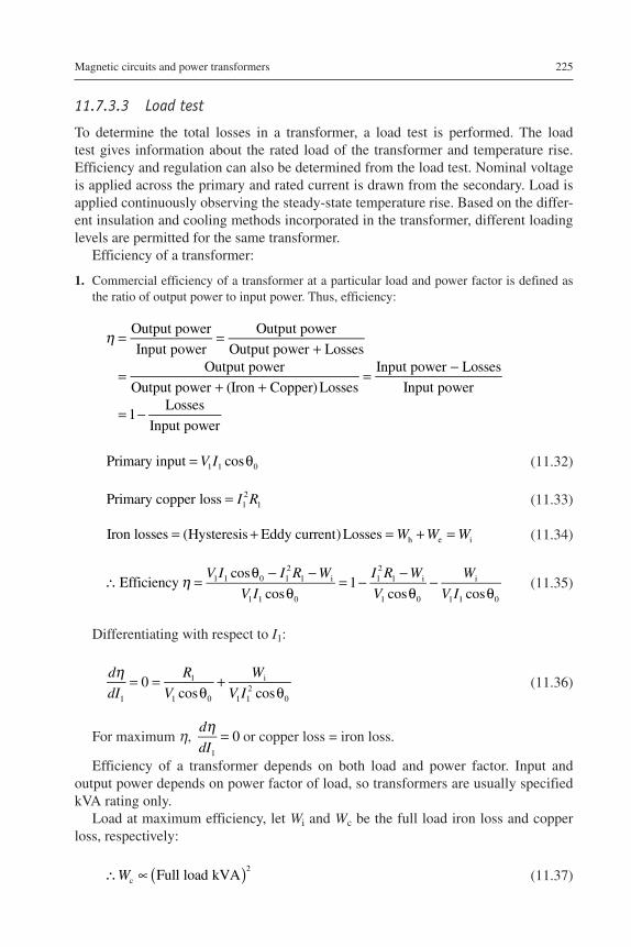
11.7.3.3 Load test
To determine the total losses in a transformer, a load test is performed. The load test gives information about the rated load of the transformer and temperature rise. Efficiency and regulation can also be determined from the load test. Nominal voltage is applied across the primary and rated current is drawn from the secondary. Load is applied continuously observing the steady-state temperature rise. Based on the differ-ent insulation and cooling methods incorporated in the transformer, different loading levels are permitted for the same transformer.
Efficiency of a transformer:
1. Commercial efficiency of a transformer at a particular load and power factor is defined as the ratio of output power to input power. Thus, efficiency:
η = =+
=+ +
= −
= −
Output power
Input power
Output power
Output power LossesOutput power
Output power (Iron Copper) Losses
Input power Losses
Input power
1Losses
Input power
= θV IPrimary input cos1 1 0 (11.32)
= I RPrimary copper loss 12
1 (11.33)
= + = + =W W WIron losses (Hysteresis Eddy current) Losses h e i (11.34)
η∴ =θ − −
θ= −
−θ
−θ
V I I R W
V I
I R W
V
W
V IEfficiency
cos
cos1
cos cos1 1 0 1
21 i
1 1 0
12
1 i
1 0
i
1 1 0 (11.35)
Differentiating with respect to I1:
η= =
θ+
θd
dI
R
V
W
V I0
cos cos1
1
1 0
i
1 12
0 (11.36)
For maximum η, η =d
dI0
1
or copper loss = iron loss.
Efficiency of a transformer depends on both load and power factor. Input and output power depends on power factor of load, so transformers are usually specified kVA rating only.
Load at maximum efficiency, let Wi and Wc be the full load iron loss and copper loss, respectively:
( )∴ ∝W Full load kVAc
2
(11.37)
η=Output powerInput power=Output powerOutput power+Losses=Out-put powerOutput power+Iron+CopperLosses=Input power−LossesInput -power=1−LossesInput power
Primary input=V1I1cos1
Primary copper loss=I12R1
Iron losses=(Hysteresis+Eddy current) Losses=Wh+We=Wi
∴ Efficiency η=V1I1cos1−I12R1−WiV1I1cos1=1−-I12R1−WiV1cos1−WiV1I1cos1
dηdI1=0=R1V1cos1+WiV1I12cos1
dηdI1=0
∴Wc∝Full load kVA2

226 Electric Renewable Energy Systems
If x is the load, when the efficiency is maximum, then:
∝W x Wi2
c (11.38)
( )∴ =W
W x
Full load kVAc
i
2
2
(11.39)
Load at maximum efficiency (x) is:
( )=
xW
WFull load kVA
Iron lossses
Full load copper lossesi
c
1/2
(11.40)
11.7.3.3.1 All day efficiencyTransformers are employed for energy distribution 24 h a day. In a day the sec-ondary is loaded throughout 24 h contributing to iron losses. But only during peak loaded conditions are copper losses significant. The performance of a transformer is judged by its operational efficiency, called all day efficiency, based on the load cycle in 24 h.
η =All day efficiencyOutput in kWh
Input in kWhall day
(11.41)
11.7.3.3.2 RegulationWhenever a transformer is loaded, terminal voltage across the secondary changes with the load variations, with the primary voltage supply held constant. The change in sec-ondary terminal voltage from no load to full load, expressed as a percentage of no-load voltage, is known as voltage regulation of a transformer:
= − ×% RegulationSecondary voltage at no load Secondary voltage at full load
Secondary voltage at no load100
(11.42)
11.8 Transformer polarity
The phase relationship of single-phase transformer voltages is described as “ polarity.” The polarity of a transformer can be either additive or subtractive. These terms de-scribe the voltage that may appear on adjacent terminals if the remaining terminals
Wi∝x2Wc
∴WcWi=Full load kVA2x2
x=Full load kVAIron losss-es WiFull load copper loss-es Wc1/2
A l l d a y e f f i c i e n -cy ηall day=Output in kWhIn-put in kWh
% Regulation=Secondary volt-age a t no l oad−Secondary voltage at full loadSecond-ary voltage at no load× 100

Magnetic circuits and power transformers 227
are jumpered together. Although the technical definition of polarity involves the rela-tive position of primary and secondary bushings, the position of primary bushings is always the same according to standards. Therefore, when facing the secondary bush-ings of an additive transformer, the X1 bushing is located to the right (of X3), while for a subtractive transformer, X1 is farthest to the left. To complicate this definition, a single-phase pad-mounted transformer built to IEEE standard Type 2 will always have the X2 mid-tap bushing on the lowest right-hand side of the low-voltage slant pattern. Polarity has nothing to do with the internal construction of the transformer windings, only with the routing of leads to the bushings. Polarity only becomes im-portant when transformers are being paralleled or banked. Single-phase polarity is illustrated in Figure 11.12.
11.9 Transformers in parallel
For supplying a load in excess of the rating of an existing transformer, two or more transformers may be connected in parallel with the existing transformer. It is usually economical to install another transformer in parallel instead of replacing the existing transformer by a single larger unit. The cost of a spare unit in the case of two parallel transformers (of equal rating) is also lower than that of a single large transformer. In addition, it is preferable to have a parallel transformer because of reliability. With this, at least half the load can be supplied with one transformer out of service. For parallel connection of transformers, primary windings of the transformers are connected to source bus-bars and secondary windings are connected to the load bus-bars. There are various conditions that must be fulfilled for the successful parallel operation of transformers. These are as follows:
1. The line voltage ratios of the transformers must be equal (on each tap): If the transform-ers connected in parallel have slightly different voltage ratios, then due to the inequality of induced EMFs in the secondary windings, a circulating current will flow in the loop formed by the secondary windings under the no-load condition, which may be much greater than the normal no-load current. The current will be quite high as the leakage impedance is low. When the secondary windings are loaded, this circulating current will
Figure 11.12 Single-phase polarity.

228 Electric Renewable Energy Systems
tend to produce unequal loading on the two transformers, and it may not be possible to take the full load from this group of two parallel transformers (one of the transformers may become overloaded).
2. The transformers should have equal per-unit leakage impedances and the same ratio of equivalent leakage reactance to the equivalent resistance (X/R): If the ratings of both the transformers are equal, their per-unit leakage impedances should be equal in order to have equal loading of both the transformers. If the ratings are unequal, their per-unit leakage im-pedances based on their own ratings should be equal so that the currents carried by them will be proportional to their ratings. In other words, for unequal ratings, the numerical (ohmic) values of their impedances should be in inverse proportion to their ratings to have current in them in line with their ratings. A difference in the ratio of the reactance value to resistance value of the per-unit impedance results in a different phase angle of the currents carried by the two paralleled transformers; one transformer will be working with a higher power factor and the other with a lower power factor than that of the combined output. Hence, the real power will not be proportionally shared by the transformers.
3. The transformers should have the same polarity: The transformers should be properly con-nected with regard to their polarity. If they are connected within correct polarities then the two EMFs, induced in the secondary windings that are in parallel, will act together in the local secondary circuit and produce a short circuit.
The previous three conditions are applicable to both single-phase as well as three-phase transformers. In addition to these three conditions, two more conditions are essential for the parallel operation of three-phase transformers:
4. The transformers should have the same phase sequence: The phase sequence of line voltages of both the transformers must be identical for parallel operation of three-phase transformers. If the phase sequence is incorrect, in every cycle each pair of phases will be short circuited.
5. The transformers should have the zero relative phase displacement between the secondary line voltages: The transformer windings can be connected in a variety of ways, which pro-duce different magnitudes and phase displacements of the secondary voltage. All the trans-former connections can be classified into distinct vector groups. Each vector group notation consists of an uppercase letter denoting HV connection, a second lowercase letter denoting LV connection, followed by a clock number representing LV winding’s phase displacement with respect to HV winding (at 12 o’clock). There are four groups into which all possible three-phase connections can be classified:a. Group 1: Zero phase displacement (Yy0, Dd0, Dz0)b. Group 2: 180° phase displacement (Yy6, Dd6, Dz6)c. Group 3: −30° phase displacement (Yd1, Dy1, Yz1)d. Group 4: +30° phase displacement (Yd11, Dy11, Yz11)
In the previously mentioned notations, letters y (or Y), d (or D), and z represent star, delta, and zigzag connections, respectively. In order to have zero relative phase displacement of secondary side line voltages, the transformers belonging to the same group can be paralleled. For example, two transformers with Yd1 and Dy1 connec-tions can be paralleled. The transformers of groups 1 and 2 can only be paralleled with transformers of their own group. However, the transformers of groups 3 and 4 can be paralleled by reversing the phase sequence of one of them. For example, a transformer with Yd11 connection (group 4) can be paralleled with that having Dy1 connection (group 3) by reversing the phase sequence of both primary and secondary terminals of the Dy1 transformer.

Magnetic circuits and power transformers 229
11.10 Three-phase transformer connections
Transformer power levels range from low-power applications, such as consumer elec-tronics power supplies, to very high power applications, such as power distribution systems. For higher power applications, three-phase transforms are commonly used. A three-phase transformer is constructed as a single unit with a bank of transformers, that is, three numbers of identical single-phase transformers connected in required form. In a single-phase transformer, only two coils, namely primary and secondary, are available whereas in a three-phase transformer there will be three numbers of pri-mary coils and three numbers of secondary coils. The coils are connected in various methods as listed in Table 11.1 to obtain different voltage levels.
• An advantage of ∆–∆ connection is that if one of the transformers fails or is removed from the circuit, the remaining two can operate in the open ∆ or V connection. This way, the bank still delivers three-phase currents and voltages in their correct phase relationship. However, the capacity of the bank is reduced to 57.7% of its original value.
• In the Y–Y connection, only 57.7% of the line voltage is applied to each winding but full line current flows in each winding. The Y–Y connection is rarely used.
• The ∆–Y connection is used for stepping up voltages since the voltage is increased by the transformer ratio multiplied by 3.
11.11 Special transformer connection
An air core transformer is a special transformer, used in radio frequency circuits. As the name implies, its windings are wrapped around a nonmagnetic material in the form of a hollow tube. Though the degree of coupling (mutual inductance) is much less,
Table 11.1 Various three-phase transformer connections
S. no.
Primary configuration
Secondary configuration
Symbolic representation
Primary or secondary
Line voltage
Line current
1. Delta (mesh) Delta (mesh) ∆–∆ =V nVl l=I
I
nll
2. Delta (mesh) Star (wye) ∆–Y =V nV3l l
=II
n3ll
3. Star (wye) Delta (mesh) Y–∆=V
nV
3ll =I
I
n3l
l
4. Star (wye) Star (wye) Y–Y =V nVl l=I
I
nll
5. Interconnected star
Delta (mesh) –∆
6. Interconnected star
Star (wye) –Y
Vl=n VlIl=Iln
Vl=3 n VlIl=Il3 n
Vl=n Vl3Il=3Iln
Vl=n VlIl=Iln

230 Electric Renewable Energy Systems
ferromagnetic cores (eddy current loss, hysteresis, saturation, etc.) are completely eliminated. In high-frequency applications, the effects of iron losses are more prob-lematic. An example of air core transformers is the tesla coil, which is a resonant, high-frequency, step-up transformer used to produce extremely high voltages.
A Scott-connected transformer is a type of circuit device used to convert a three-phase supply (3-, 120-degree phase rotation) into a two-phase (2-, 90-degree phase rotation) supply, or vice versa. The Scott connection evenly distributes a balanced load between the phases of the source.
11.12 Parallel operation of three-phase transformers
Ideal parallel operation between transformers occurs when (1) there are no circulat-ing currents on open circuit, and (2) the load division between the transformers is proportional to their kVA ratings. These requirements necessitate that any two or more three-phase transformers, which are desired to be operated in parallel, should possess:
1. The same no-load ratio of transformation2. The same percentage impedance3. The same resistance to reactance ratio4. The same polarity5. The same phase rotation6. The same inherent phase-angle displacement between primary and secondary terminals The previously mentioned conditions are characteristic of all three-phase transformers
whether two winding or three winding. With three-winding transformers, however, the following additional requirement must also be satisfied before the transformers can be designed suitable for parallel operation:
7. The same power ratio between the corresponding windings
Table 11.2 gives the possible combinations of transformers that can be operated in parallel.
The methods to check for synchronization of transformers are done using a synchroscope or synchronizing relay. The advantages of parallel operation of trans-formers are:
Table 11.2 Parallel operation of three-phase transformers
S. no.Vector group of transformers that will operate in parallel
Vector group of transformers that will NOT operate in parallel
1. Transformer 1 Transformer 2 Transformer 1 Transformer 22. ∆∆ ∆∆ or Yy ∆∆ ∆y3. Yy Yy or ∆∆ ∆y ∆∆4. ∆Y ∆y or Y∆ Y∆ Yy5. Y∆ Y∆ or ∆y Yy Y∆

Magnetic circuits and power transformers 231
1. Maximize electrical system efficiency2. Maximize electrical system availability3. Maximize power system reliability
But during the parallel operation of three-phase transformers, the magnitude of short-circuit currents, risk of circulating currents, bus rating, and reduction in trans-former impedance make the circuit complex in providing protective mechanisms.
11.13 Autotransformers
In an autotransformer, the primary and secondary windings are linked together both electrically and magnetically. Therefore it is economical for the same VA rating as windings are reduced, but the disadvantage is that it does not have isolation between primary and secondary windings. The winding can be designed with multiple tapping points, to provide different voltage points along its secondary winding. The winding diagram and the number of windings in primary and secondary (Np and Ns, respec-tively), current, and voltage across primary and secondary are shown in Figure 11.13.
11.14 Three-winding transformers
In certain high rating transformers, one winding in addition to its primary and secondary winding is used, called a tertiary winding transformer. Because of this third winding, the transformer is called a three-winding transformer. The advantage of using a tertiary winding in a transformer is to meet one or more of the following requirements:
1. It reduces the unbalancing in the primary due to unbalancing in three-phase load.2. It redistributes the flow of fault current.
Figure 11.13 Winding diagram of an autotransformer.

232 Electric Renewable Energy Systems
3. Sometimes it is required to supply an auxiliary load at different voltage levels in addition to its main secondary load. This secondary load can be taken from the tertiary winding of the three-winding transformer.
4. As the tertiary winding is connected in delta formation in a three-winding transformer, it assists in limiting fault current in the event of a short circuit from line to neutral.
5. A star–star transformer comprising three single units or a single unit with five limb core offers high impedance to the flow of unbalanced load between the line and neutral.
11.15 Instrument transformers
Instrument transformers are used for transforming the magnitude of current (typically 1 A or 5 A at secondary) and voltage (typically 120 V at secondary) from one level to another. Also instrument transformers can be used as an isolation transformer for safety purposes. Various types of instrument transformers, namely current transform-ers, inductive voltage transformers, capacitive voltage transformers, combined cur-rent/voltage transformers, and station service voltage transformers, are designed to transform high current and high voltage levels down to low current and low voltage outputs in a known and accurate proportion for a specific application.
Potential transformers consist of two separate windings on a common magnetic steel core. One winding consists of fewer turns of heavier wire on the steel core and is called the secondary winding. The other winding consists of a relatively large number of turns of fine wire, wound on top of the secondary, and is called the primary winding.
Current transformers are constructed in various ways. One method is quite simi-lar to that of the potential transformer in that there are two separate windings on a magnetic steel core. But it differs in that the primary winding consists of a few turns of heavy wire capable of carrying the full load current while the secondary winding consists of many turns of smaller wire with a current carrying capacity of between 5 A and 20 A, dependent on the design. This is called the wound type due to its wound primary coil. Another very common type of construction is the so-called “window,” “through,” or donut type current transformer in which the core has an opening through which the conductor carrying the primary load current is passed. This primary conduc-tor constitutes the primary winding of the current transformer (one pass through the “window” represents a one turn primary), and must be large enough in cross-section to carry the maximum current of the load.
The operation of instrument transformers differs from power transformers. The secondary winding of an instrument transformer has a very small impedance called burden, such that the instrument transformer operates under short-circuit conditions. The burden (expressed in ohms) across the secondary of an instrument transformer is also defined as the ratio of secondary voltage to secondary current. This helps to determine the volt-ampere loading of the instrument transformer.
The major applications of instrument transformers include:
1. Revenue metering for electric utilities, independent power producers, or industrial users2. Protective relaying for use with switchgear to monitor system current and voltage levels3. High accuracy wide current range use for independent power facilities4. Station service power needs within substations or for power needs at remote sites

Magnetic circuits and power transformers 233
11.16 Third harmonics in transformers
In addition to the operation of transformers on the sinusoidal supplies, harmonic be-havior is important as the size and rating of the transformer increases. In recent times, transformers have been designed to operate at closed levels of saturation in order to reduce the weight and cost of the core used. Because of this and hysteresis, the trans-former core behaves as a nonlinear component and generates harmonic currents. If a sinusoidal voltage is applied to the primary of a transformer, the flux wave will vary as a sinusoidal function of time, but the no-load current wave will be distorted because the hysteresis loop contains a pronounced third harmonic. Figure 11.14 represents the hysteresis loop taken to the maximum flux density and the manner in which the shape of the magnetizing current can be obtained and plotted. In Figure 11.14, at any instant of the flux density wave the ampere-turns required to establish are read out and plotted by traversing the hysteresis loop.
To produce a flux density of NP requires 0N ampere-turns per meter:
′ ′ =N P NP
The ampere-turns per meter are plotted as N'A in Figure 11.14b. To produce a flux density MR requires 0M ampere-turns per meter:
= ′= ′ ′
0 M M BMR M R
N9P9=NP
0M=M9BMR=M9R9
Figure 11.14 (a) Hysteresis loop and (b) magnetizing current.

234 Electric Renewable Energy Systems
In brief, the various abscissas of Figure 11.14a are plotted as ordinates to determine the shape of the current wave on Figure 11.14b. This is continued until a sufficient number of points are obtained. The use of a suitable constant changes the wave BAX from ampere-turns per meter to amperes. Such a wave represents the magnetizing component and the hysteresis component of the no-load current. It reaches the maximum at the same time as the flux wave, but the two waves do not go through zero simultaneously. The sinusoidal flux density represents the sinusoidal voltage, whereas the plot of magnetizing current rises sharply, saturates quickly, and is thereby distorted. This magnetizing current can be analyzed with Fourier series. The harmonic components are obtained from this Fourier analysis. The har-monic spectrum of the magnetizing current waveform reveals a very high percent-age of third harmonics. These harmonic currents produce harmonic fields in the core and harmonic voltages in the windings. A relatively small value of harmonic fields produces substantial magnitudes of harmonic voltages. For example, a 10% magnitude of third harmonic flux produces a 30% magnitude of third harmonic voltage. These effects become even more pronounced for higher order harmonics. The no-load current can be considered to be made up of approximately two sine components (loss component and magnetizing component) and the nonsinusoidal component with dominant third harmonics. The sum of sine and nonsine waves forms a distorted waveform.
In the case of single-phase transformers connected to form a three-phase star- connected bank, the fundamental voltages supplied will produce voltages in the in-dividual transformers that contain third harmonics. These third harmonics for all the three transformers will be in time phase. Each voltage between the neutral of the pri-maries and the lines will contain both a fundamental component and a third harmonic component, and as a result the secondary voltage of each transformer will contain both fundamental and third harmonic components.
The effects of the harmonic currents are:
1. Additional copper losses2. Increased core losses3. Increased neutral current and overheating of neutral conductor4. Increased EMI with communication networks
On the other hand, the harmonic voltages of the transformer cause:
1. Increased dielectric stress on insulation2. Resonance between winding reactance and feeder capacitance
11.17 Transformers in a microgrid
With technological improvements, design, materials, etc. of power transformers, autotransformers, and instrument transformers, performance has increased. In renew-able energy integrated microgrids, AC and direct current (DC) supply are available and hence solid-state transformers and smart transformers are being developed and marketed to cater for the features of microgrids and smart grids.

Magnetic circuits and power transformers 235
11.17.1 Solid-state transformers
The advantages and limitations of conventional transformers when power quality is a major concern are as follows:
Advantages:
1. Relatively economical2. Highly reliable3. Quite efficient
Limitations:
1. Sensitive to harmonics2. Voltage drop under load3. No protection from system disruptions and overloads4. Environmental concerns regarding mineral oil5. Poor performance under DC-offset load unbalances6. No power factor improvement
The solid-state transformers (SSTs) are designed with different topologies based on its application:
1. AC to AC buck converter: the salient points are that,a. Transformation of the voltage level directly without any isolation transformerb. Switches must be capable of blocking full primary voltage during OFF state and conduct-
ing full secondary current during ON statec. Difficult to control series-connected devicesd. Lack of magnetic isolatione. Inability to correct load power factor
2. SST without a DC link:a. Transformer weight and size reducedb. Provides isolationc. No power factor improvement is possible
3. SST with a DC link:a. Reduced size due to a high-frequency transformerb. Power factor improvement is possiblec. Multilevel converter topologies can be applied to achieve high voltage levels (e.g.,
11 kV, 22 kV)d. High cost and low efficiencye. It is a three-stage topology: most popular now
SSTs that can be widely used in microgrid applications are relatively advantageous with respect to power quality.
Advantages:
1. An excellent utilization of distributed renewable energy resources and distributed energy storage devices
2. Power factor control3. Fast isolation under fault conditions due to a controlled SST4. Control of both AC and DC loads can be done using the SST scheme5. Improved power quality6. DC and alternative frequency AC service options

236 Electric Renewable Energy Systems
7. Integration with system monitoring and advanced distribution8. Reduced weight and size9. Elimination of hazardous liquid dielectrics
Limitations:
1. Multiple power conversion stages can lower the overall efficiency2. DC-link capacitors are required3. The transformer lifetime can be shorter due to storage devices
11.17.2 The smart transformers
The smart transformer is a smart device for integrating with the distribution grid, solar- wind renewable energy storage, and electric vehicles. The components of a smart transformer include power conversion system and built-in STATCOM functions. The smart transformer can be fully controlled through Internet or wireless communication systems. It uses high-voltage semiconductor switches based on an AC/DC rectifier, DC/DC converter, high-voltage and high-frequency transformer, DC/AC inverter, and their switching control circuitry. This is expected to be a critical component in the development of smart grids.
11.18 Summary
In this chapter, the fundamentals of magnetic circuits and basic concepts of power transformers, types, and testing methods were discussed in detail. The development of equivalent circuit efficiency and regulation calculation of the transformer was elaborated.
References
[1] Johnson JR. Electric circuits – Part-I direct current. San Francisco, CA: Rinehart Press; 1970.
[2] Puchstein AF, Lloyd TC, Conrad AG. Alternating current machines. Mumbai, India: Asia Publishing House; 1950.
[3] Richardson DV. Rotating electric machinery and transformer technology. Richmond, VA: Reston Publishing Company, Inc; 1982.
[4] Deshpande MV. Design and testing of electrical machines. New Delhi, India: Prentice Hall of India; 2010.
Related Documents