11-1 Lifting/Blocking/Clamping Table of Contents Hoists ............................................................................................................................................................................. 11-3 Jacks............................................................................................................................................................................ 11-22 Stands .......................................................................................................................................................................... 11-30 Miscellaneous ........................................................................................................................................................... 11-39 Lifting/Blocking/Clamping

11 Lifting Blocking Clamping.pdf
Oct 29, 2015
Lifting Blocking Clamping
Welcome message from author
This document is posted to help you gain knowledge. Please leave a comment to let me know what you think about it! Share it to your friends and learn new things together.
Transcript

11-1
Lifting/Blocking/Clam
pingTable of Contents
Hoists ............................................................................................................................................................................. 11-3
Jacks............................................................................................................................................................................ 11-22
Stands .......................................................................................................................................................................... 11-30
Miscellaneous ........................................................................................................................................................... 11-39
Lifting/Blocking/Clamping

11-2
Lifti
ng/B
lock
ing/
Clam
ping
Table of Contents

2635247
11-3
Lifting/Blocking/Clam
pingHoists
Hoists
1U-7485 Heavy-Duty Mobile Lifting Crane, 1996 kg (4,400 lb)Warranty: Six Months
• Versatile features and rugged construction of OTC heavy-duty crane let you handle just about any lifting job with speed
• Folds into a compact package for storage• Leg spread adjusts to clear vehicles wheels, other obstacles for close-in work• Telescoping boom extension gives additional reach• 2-speed hydraulic hand pump provides fast boom travel (descent of boom is
under precise control of operator)• Equipped with roller-bearing mounted wheels, crane rolls smoothly into position
or storage location• Steering dolly provides easy maneuverability• Space saving Fold-Away featureOptional Hydraulics (Sold Separately)• For greater speed and ease of operation, your crane can be powered with an
air-driven, air/hydraulic pump such as the 1U-7544Capacity, boom extracted 1996 kg (4400 lb)Capacity, boom extended 1497 kg (3300 lb)Maximum boom height - Boom extracted 281.9 cm (111 in)Maximum boom height - Boom extended 309.9 cm (122 in)Overall height, boom horizontal 208.3 cm (82 in)Overall length 226.1 cm (89 in)Minimum throat width 63.5 cm (25 in)Inside leg length 146.1 cm (57 1/2 in)Effective boom reach (retracted) 90.22 cm (35 1/2 in)Effective boom reach (extended) 128.3 cm (50 1/2 in)Inside leg width (3-position) 66.0 - 101.6 cm (26 - 40 in), 133.4 cm (52
1/2 in)Leg height 24.13 cm (9 1/2 in)Dolly wheel diameter 12.7 cm (5 in)Wheel diameter 20.32 cm (8 in)Caster diameter 15.24 cm (6 in)Floor space, folded 78.7 x 106.7 cm (31 x 42 in)Height, folder 218.4 cm (86 in)Lifting chain 46.7 cm (18 3/8 in)Weight 291 kg (642 lb)Supplier part no. 1820
Part Number Description1U-7544 Hydraulic Hand Pump1U-7485 Heavy-Duty Mobile Lifting Crane, 1996 kg (4,400 lb)

2635268
11-4
Lifti
ng/B
lock
ing/
Clam
ping
Hoists
1U-7555 Mobile Lifting Crane, 2,722 kg (6,000 lb)Warranty: Manufacturer’s Two Year Limited
• Heavyweight,retractable-leg,mobilefloorcraneequippedwithelectric/hydrau-lic (115V) pump with remote motor control
• 3 boom positions give you capacities of 1,814, 2,268 and 2,722 kg (4,000, 5,000 and 6,000 lb) — enough to lift the biggest engines
• Features a boom swivel, and extendable legs• Vertical and lateral swing• Equipped with an electric/hydraulic pump with remote control for raising and
lowering• Includesasteeringdollyformaneuverability;dollyalsoactsasafloorlockby
liftingtherearwheeloffthefloor• Built to take all the hard use you can give it• Ideal for freeing up an overhead crane, letting you pull engines from any bay in
the shop• Offers greater mobility and versatility than installing and overhead crane or
gantry• Coupled with the 6V-3145 Load Leveler (sold separately) and the 1U-5750
Revolver (sold separately) engine stand this crane gives you a complete set of heavy-duty engine equipment
Repair InformationSPX Service Repair755 Eisenhower DriveOwatonna, MN 55060Attn: Repair DepartmentPhone: 800-344-4013Visit the SPX Repair Track web link to complete and submit the form for proper authorization: https://repairtrack.spx.comBoom Capacity Ext. 4,000 Center 5,000 Ret. 6,000Max. boom height 411.16 cm (161 7/8
in)382.75 cm (150 11/16 in)
354.33 cm (139 1/2 in)
Min. boom height 15.24 cm (6 in) 44.13 cm (17 3/8 in) 73.03 cm (28 3/4 in)Overall height, boom horizontal
220.98 cm (87 in) 220.98 cm (87 in) 220.98 cm (87 in)
Overall length 327.98 cm 289.24 cm 249.56 cmLegs in storage position: 807/8 in
(129 1/8 in) (113 7/8 in) (98 1/4 in)
Inside leg length 232.89 cm (91 11/16 in)
193.36 cm (76 1/8 in) 109.86 cm (43 1/4 in)
Effective boom horizontal reach
239.40 cm (94 1/4 in) 200.03 cm (78 3/4 in) 160.66 cm (63 1/4 in)
Outside leg width 151.77 cm 146.69 cm 141.61 cmLegs in storage position: 531/2 in
(59 3/4 in) (57 3/4 in) (55 3/4 in)
Boom swing 91.44 cm (36 in) 78.74 cm (31 in) 66.04 cm (26 in)Inside leg width -- 90.81 cm (35 3/4 in) --Leg height -- 23.02 cm (9 1/16 in) --Dolly wheel diam-eter
-- 12.70 cm (5 in) --
Wheel diameter -- 20.32 cm (8 in) --Supplier part no.: 1814
(Continued)

2635268
2635289
2635318
11-5
Lifting/Blocking/Clam
pingHoists
1U-7555 Mobile Lifting Crane, 2,722 kg (6,000 lb) (Continued)Warranty: Manufacturer’s Two Year Limited
Part Number Description1U-7555 Mobile Lifting Crane, 2,722 kg (6,000 lb)
Hand HoistsWarranty: Manufacturer’s Five Year Against Defects In Workmanship
European CE Compliant• Standard Load Limiter for simple, automatic overload protection• Weston-style braking system provides reliable positive load control• Powdercoatedfinishforcorrosionprotection• All internal gears and pinions are heat treated steel for high strength and long life.• Chain guide and stripper assures load chain alignment• Fullymachinedprecision4-pocketliftwheelforbetterchainfitandreducedwearallowingforaccuratemovementofthe
load chain• Hardened alloy steel load chain assures high strength and long wear life• Minimal maintenance, easily disassembled, requires no special tools• Meets ASME B30.16 and European CE StandardRepair InformationColumbus-McKinnonAudubon and Sylan ParkwayAmherst, NY 14228Phone: (800) 888-0985Fax: (716) 689-5644Website: www.cmindustrial.com
Part Number Capacity (Tons) Standard LiftApproximate Shipping Weight
Shortest Distance Between Hooks
Chain Pull to Lift Load
No. of Chain Falls
398-5484 0.5 3 m (10 ft) 10.4 kg (23 lb) 0.30 m (11.8 in) 44 lb 1398-5485 1.0 3 m (10 ft) 11.8 kg (26 lb) 0.34 m (13.2 in) 54 lb 1398-5486 2.0 3 m (10 ft) 20.4 kg (45 lb) 0.40 m (15.6 in) 74 lb 1398-5487 5.0 3 m (10 ft) 55.3 kg (122 lb) 0.65 m (25.7 in) 76 lb 2398-5488 10.0 3 m (10 ft) 95.3 kg (210 lb) 0.83 m (32.5 in) 102 lb 3
Electric Chain HoistsWarranty: Manufacturer’s One Year Against Defects In Workmanship
• Heavy-duty motors• Workings are completely enclosed and compact for low headroom• Safety features include: Lodestar Protector®, a friction clutch assembly de-
signed to stop the hoist when overloading occurs (a dual braking system — heavy-duty magnetic and regenerative — plus upper and lower limit features)
• Snap action control station carries only 115 volts and is completely sealed, weatherproofed and waterproofed
• Gears receive lifetime lubrication at factoryNOTE:Due to various applications, suspension for hoist must be ordered separately. Please see part numbers listed under accessories.Repair InformationColumbus-McKinnonAudubon and Sylan ParkwayAmherst, NY 14228Phone: (800) 888-0985Fax: (716) 689-5644Web site: www.cmindustrial.com
(Continued)

2635318
2690891
2828693
11-6
Lifti
ng/B
lock
ing/
Clam
ping
Hoists
Electric Chain Hoists (Continued)Warranty: Manufacturer’s One Year Against Defects In Workmanship
Part Number Max. Capacity Lifting Speed/Min Maximum Lift Motor HP Electrical Requirements4C-6953 1/2 ton 4.88 m/min (16 fpm) 4.5 m (15 ft) 1/2 Hp 115 V/1 Phase/60 Hz4C-6954 1 ton 4.88 m/min (16 fpm) 4.5 m (15 ft) 1 Hp 115 V/1 Phase/60 Hz4C-6956 2 ton 2.44 m/min (8 fpm) 6.1 m (20 ft) 1 Hp 115 V/1 Phase/60 Hz4C-6958 3 ton 1.68 m/min (5.5 fpm) 6.1 m (20 ft) 1 Hp 115 V/1 Phase/60 Hz4C-6959 3 ton 1.68 m/min (5.5 fpm) 6.1 m (20 ft) 1 Hp 230/460 V/3 Phase/60 Hz
Accessories
Part Number Length of Lift Use with HoistRigid Hook Suspension
1U-6362 -- 1U-9197, 4C-69541U-9812 -- 1U-9810, 4C-6958, 4C-69591U-6361 -- 1U-9195, 4C-6953
Rigid Lug Suspension1U-9216 -- 4C-6955, 4C-6956
Chain Container1U-9561 15 ft 1U-9194, 1U-9196, 1U-9197, 4C-69541U-9559 20 ft 1U-9195, 4C-69531U-9562 15 ft 4C-69551U-9560 20 ft 1U-9197, 4C-6954, 1U-9194, 1U-91961U-9813 15 ft 1U-9810, 4C-6958, 4C-6959
362-0960 Spreader Bar AssemblyWarranty: Six Months
European Union Compliant, CE marked• Requires double chain sling with 12.7 mm (1/2 in) and 6V-3145 Load Leveler (not
supplied with tool)• Adjustable length from 1067 to 1677 mm (42.0 to 66.0 in) in increment of 76 mm
(3.0 in)• Used with a double sling chain to lift cab vertically at attach points, eliminates
side loading• End pin keeps chain from becoming disengaged when device is being usedSpecificationsLifting Capacity (WLL) 454 kg (1000 lb)Adjustable Length 1067 mm (42.0 in) to 1677 mm (66.0 in)Incremental Adjustment 76 mm (3.0 in)Tube Size (External) 44.5 mm (1.75 in)Tube Size (Internal) 38.1 mm (1.50 in)
Part Number Description362-0960 Spreader Bar Assembly

2636310
2635353
11-7
Lifting/Blocking/Clam
pingHoists
6V-3145 Load Leveler6V-6146 Load LevelerWarranty: Six Months
• Provides a much improved design over the conventional spreader bar• Carriage on the main support beam is moved by turning the lead screw, which
permitsfineadjustmentofthetiltangleofthecomponentbeinglifted• Lead screw can be turned manually or with air-powered tools• Spreader bar adjustment is secured with locking bolts• Chain grade 80 (ASTM)
Item Part Number DescriptionMax. Lifting Capacity
Distance Betw. Hooks Minimum
Distance Betw. Hooks Maximum
Chain Grade (ASTM) Weight
1 6V-3144 Chain 1 -- -- -- -- ---- 6V-3145 Load Leveler (Optional) 2,721 kg
(5,998.77 lb)76.2 cm (30 in) 116.8 cm (46 in) 80 34 kg (74.98 lb)
-- 6V-6146 Load Leveler 4,535 kg (9,997.95 lb)
91.4 cm (36 in) 142.2 cm (56 in) 80 43.1 kg (95 lb)
1 Use with 6V-3145 and 6V-6146
309-2793 Load Leveling AssemblyEssential ToolModel: 994 and 994D Wheel loaders with 3512 Engines, Off-Highway Trucks with C175 Engines, Other similar engine lifting applicationsWarranty: Manufacturer’s Limited Lifetime on Lifting Device, Manufacturer’s Limited 6 Month on Chain, Wire Rope, and Hoses
European Union compliant, CE marked• Replaces canceled 137-4370 Leveling Assembly• Used to lift, level, and position heavy loads such as 3512 and C175 Engines and
can also be used on transmissions or other similar components• Used with overhead lifting device rated for lifting heavy loads• Adjust and keep load level during lifting procedures by retracting or extending
hydraulic cylinder on leveling beam• Eliminates constant readjustment (raising and lowering) of lifting device to
obtain both stable and level load• Uses heavy-duty, air-over-hydraulic system to allow for small adjustments so
load can be accurately positioned during removal and installation• Increased load rating over previous design allows tooling to be used on more
applications• Includes remote-operation, air-hydraulic switch with 7.62 m (25.0 ft) air hose• Removable caster assemblies provide mobility for load leveler• Removable tool box stores and protects remote switch, air hose, and related
components• 310-7787 Wire Rope Assembly may be purchased as replacement for 309-2794
Chain AssemblyRepair InformationSPX Service Repair755 Eisenhower DriveOwatonna, MN 55060Attn: Repair DepartmentPhone: 800-344-4013
(Continued)

2635353
2635385
11-8
Lifti
ng/B
lock
ing/
Clam
ping
Hoists
309-2793 Load Leveling Assembly (Continued)Essential ToolModel: 994 and 994D Wheel loaders with 3512 Engines, Off-Highway Trucks with C175 Engines, Other similar engine lifting applicationsWarranty: Manufacturer’s Limited Lifetime on Lifting Device, Manufacturer’s Limited 6 Month on Chain, Wire Rope, and Hoses
Visit the SPX Repair Track web link to complete and submit the form for proper authorization: https://repairtrack.spx.comReferenceNEHS1011, Tool Operating Manual, 309-2793 Load TilterCapacity 22,680 kg (50,000 lb)Length 299.7 cm (118.0 in)Width 29.2 cm (11.5 in)Height 129.5 cm (51.0 in)Weight 544 kg (1,200 lb)
Part Number Description309-2793 Load Leveling Assembly
Service/Repair Parts309-2794 Chain Assembly309-2795 Air Hose Group (Remote Switch)310-7787 Wire Rope Assembly
323-1146 Lifting GroupEssential ToolModel: C175 EnginesWarranty: Six Months
European Union compliant, CE marked• Used to remove and install C175 Engine Assembly• Used with 309-2793 Load Leveler• Sold as complete set — two lifting bars and two 323-1712 Pin Assemblies• Working Load Limit is stamped into each 323-1146 Lifting Group (Bar)• Heat-treated for added strength and durability• 323-1712 Pin Assembly is serviced separately• Lifting bars are not serviced separately• Meets the following requirements:
ANSI - ASME B30.20:2006 AS 4991:2004 CE Compliant To Machinery Safety Directive 98/37/EC EN 13155:2003
ReferenceNEHS1040, Tool Operating ManualItem Description Quantity1 Lifting Group (Bar) 2
Item Part Number Description Working Load Limit Qty.-- 323-1146 Lifting Group -- --2 323-1712 Pin Assembly 11,340 kg (25,000 lb) 2

2829531
2635409
11-9
Lifting/Blocking/Clam
pingHoists
336-7250 Adjustable Lifting BarModel: 795F AC Off-Highway Truck, C175 EngineWarranty: Six Months
European Union compliant, CE marked• Used to remove and install C175 Engine Assembly on 795F AC Off-Highway Truck• Used in pairs with 309-2793 Load Leveler (attach at outer pin locations on load
leveler)• Working load limit is stamped into each tool• Adjustable design allows use in many other lifting applications• Heat-treated for strength and durability• Meets the following requirements:
ANSI - ASME B30.20:2006 AS 4991:2004 CE Compliant To Machinery Safety Directive 98/37/EC EN 13155:2003
ReferenceNEHS1076, Tool Operating ManualWorking load limit 11340 kg (25,000 lb)Weight 73 kg (161 lb)Adjustable length 86 to 122 cm (34.0 to 48.0 in) in 5 cm (2.0
in) increments
Part Number Description336-7250 Adjustable Lifting Bar
Load PositionersWarranty: Manufacturer’s Two Year Limited
• Used with a crane or hoist• Usefulfortiltingheavyorbulkyassembliesinconfinedareas• Forusewithfloorcranesonly.Nottobeusedwithoverheadhoistsorcranes.• 138-7575 Link Bracket (2) is part of 9S-9101 and 9S-9100ReferenceNEHS0823, Tool Operating ManualRepair InformationSPX Service Repair755 Eisenhower DriveOwatonna, MN 55060Attn: Repair DepartmentPhone: 800-344-4013Visit the SPX Repair Track web link to complete and submit the form for proper authorization: https://repairtrack.spx.com
Part Number Description Load Capacity Chain Size Chain LengthChain Grade (ASTM) Gear Ratio Drive Size
9S-9101 Sling Assembly 1814 kg (4000 lb)
7.9 mm (5/16 in) 157.48 cm (62 in) 43 82-1 5/8 in Hex
9S-9100 Hoists 907 kg (2000 lb)
6.4 mm (1/4 in) 137.16 cm (54 in) 43 34-1 5/8 in Hex

2690964
2635425
11-10
Lifti
ng/B
lock
ing/
Clam
ping
Hoists
Warning Tag - Load PositionersWarranty: Six Months
205-5688 Warning Tag• Used to warn technician against using load positioner for overhead lifting• Attach tag to all 9S-9100 and 9S-9101 Sling Assemblies (load positioners) cur-
rently in use; required because the chain is grade 43• Can be ordered free-of-charge
Part Number Description205-5688 Warning Tag
Fabric Slings, Protective Sleeve, and ShacklesModel: 769, 773, 777, 785, 789, and 793 Off-Highway Trucks and General UsageWarranty: Fabric Slings: Manufacturer’s Six Months Against Defects In Materials Or Workmanship; Shackle, Spool, and Plate: Six Months
European Union compliant, CE marked (140-7738, 140-7741)• Used to lift truck bodies or other loads with a hoist or other lifting devices (provides strength of steel without drawbacks of
weight, corrosion, or electrical conductivity)• Reducesnumberofpeoplerequiredtoperformalift—fiberslingsareupto90%lighterthanotherriggingmaterials,canbe
easily handled by a single person, stored easily, do not require lubrication or reannealing like wire rope or chains, and will not scratch or mar surfaces that they contact
• Helps reduce injuries to mechanics such as hand punctures, pinching, back strain, etc., caused by heavy metal chains and hooks
• Slings provide a high-performance, low-cost method of lifting loads using vertical, basket, and choker-type hitches• Slings provide the most inspectable lifting device by using double layered, contrasting colors and two types of visible Tell
Tail cords to indicate damage• Added protection can be gained by using a 140-7742 Protective Sleeve when slings are used in severe applications (made of
the same bulked nylon material as the outer tubes)• Sleeves feature velcro closures for easy installation and removal from slingsConstruction• Made from two complete and separate slings (cords), combined into one (provides unique back-up system, in case of fail-
ure of either cord)• Innerloadcarryingcordsareconstructedofinterwovenhighperformancefiberswhichprovideexcellentchemicalresis-
tanceandhavelessthan1%elongationatworkingload• Separate inner cords are encased in a double-walled fabric tube — inner tube is made of polyester while outer tube is
made of a bulked, abrasion-resistant nylon• All slings are labeled with model number, serial number, length, load capacities, and warningsSafety• 140-7738 and 140-7741 Slings meet all applicable national, international, and industry standards, including, but not limited to:
ASME B30.9, ANSI 120.74, and Japanese standards• 141-0288 and 141-0289 Slings meet all applicable national, international, and industry standards, including, but not limited to:
CECertificationandAustralianStandardsAS4497.1andAS4497.2• Contrasting color coded slings provide extra protection and early warning (if red inner tube or cords are visible, the sling
should be immediately removed from service and repaired by manufacturer)• 2 “Tell Tail” cords are used as an indicator of shock or overloading of sling (cords should protrude 13 mm (0.5 in) beyond
label tag and if shorter, sling should be returned to manufacturer for evaluation)• “FiberOpticTellTail”cordisusedtodetermineifinnercorefibersaredamagedorbroken—iflightfromoneendofcord
will not shine through to opposite end, the sling is probably damaged and should be returned to manufacturer for evaluation• All slings are proof-tested to twice their rated capacityHardware• A shackle is used to attach hooks, links, chains, or other lifting systems to fabric slings• Shacklesextrawidecontactareagivesincreasedloaddistributiontoslingfabricandallowsslingtoachieveupto100%of
its rated load lifting capacity• A spool keeps the loaded hook centered on the shackle pin and spreads lifting load evenly across pin• A link plate allows attachment of 2 shackles to lifting hook
(Continued)

2635425
11-11
Lifting/Blocking/Clam
pingHoists
Fabric Slings, Protective Sleeve, and Shackles (Continued)Model: 769, 773, 777, 785, 789, and 793 Off-Highway Trucks and General UsageWarranty: Fabric Slings: Manufacturer’s Six Months Against Defects In Materials Or Workmanship; Shackle, Spool, and Plate: Six Months
Repair InformationAlloy Slings1406 175th StreetHazelcrest, IL 60429Phone: (708) 647-4900Dealer Service Tools 2009ReferencesREHS0033, Special Instruction, 777D Off-Highway TruckSEHS9980, Special Instruction, 793C Off-Highway TruckSEHS9992, Special Instruction 769D/771D Off-Highway TruckSEHS9993, Special Instruction 773D/775D Off-Highway Truck
Part Number Description Length Width VerticalLifting Capacity Basket Choker
140-7738 1 Fabric Sling 2.4 m (8.0 ft) 100 mm (4 in) 9,000 kg (2,000 lb) 18,000 kg (40,000 lb) 7,200 kg (16,000 lb)141-0288 2 Fabric Sling 2.4 m (8.0 ft) 100 mm (4 in) 9,000kg (20,000 lb) 18,000 kg (40,000 lb) 7,200 kg (16,000 lb)140-7741 1 Fabric Sling 2.4 m (8.0 ft) 75 mm (3 in) 4,500 kg (10,000 lb) 9,000 kg (20,000 lb) 3,600 kg (8,000 lb)141-0289 2 Fabric Sling 2.4 m (8.0 ft) 75 mm (3 in) 4,500 kg (10,000 lb) 9,000 kg (20,000 lb) 3,600 kg (8,000 lb)140-7742 3 Protective
Sleeve600 mm (24.0 in) 250 mm (10 in) -- -- --
1 For use in all markets except Europe and Australia2 Required for use in Europe and Australia3 Recommended for use with all Fiber Slings
2688751
11-12
Lifti
ng/B
lock
ing/
Clam
ping
Hoists
Fabric Slings, Protective Sleeve, and ShacklesModel: 769, 773, 777, 785, 789, and 793 Off-Highway Trucks and General UsageWarranty: Shackle, Spool, and Plate: Six Months
143-8695 Shackle (Synthetic Sling Saver)Working load limit 18,600 kg (41,000 lb)Throat width 54 mm (2.1 in)Outside length 248 mm (9.8 in)Maximum sling width 114 mm (4.5 in)Inside depth 146 mm (5.8 in)Outside width 191 mm (7.5 in)Pin diameter 38 mm (1.5 in)Weight 8.5 kg (18.7 lb)Material Alloy steel with threaded screw pin 143-8698 Shackle Spool (Synthetic Sling Saver)Outside diameter 63.5 mm (2.5 in)Width 47.8 mm (1.88 in)Inside diameter 41.4 mm (1.63 in)Weight 1.3 kg (2.8 lb)Material Alloy steel 143-8699 Shackle Link Plate (Synthetic Sling Saver)Working load limit 18,600 kg (41,000 lb)Thickness 44.5 mm (1.75 in)Width 76.2 mm (3.0 in)Length 177.8 mm (7.0 in)Hole diameter 41.2 mm (1.62 in)Distance between holes 95.2 mm (3.75 in)Weight 4.8 kg (10.6 lb)Material Alloy steel
Part Number Description143-8699 Shackle Link Plate (Synthetic Sling Saver)143-8698 Shackle Spool (Synthetic Sling Saver)143-8695 Shackle

2635473
11-13
Lifting/Blocking/Clam
pingHoists
Nylon Lifting SlingsWarranty: Six Months
Part No. 1 Length Sling Width Eye LengthRated No. Of Body Plys Capacity Choker Vertical Basket
Endless Slings (Type V)1U-8221 0.91 m (3 ft) 25.4 mm (1 in) -- 1 1125 kg (2480 lb) 1406 kg (3100 lb) 2812 kg (6200
lb)1U-8222 1.22 m (4 ft) 25.4 mm (1 in) -- 1 1125 kg (2480 lb) 1406 kg (3100 lb) 2812 kg (6200
lb)1U-8223 1.83 m (6 ft) 25.4 mm (1 in) -- 1 1125 kg (2480 lb) 1406 kg (3100 lb) 2812 kg (6200
lb)1U-8224 2.44 m (8 ft) 25.4 mm (1 in) -- 1 1125 kg (2480 lb) 1406 kg (3100 lb) 2812 kg (6200
lb)1U-8225 1.83 m (6 ft) 50.8 mm (2 in) -- 1 2250 kg (4960 lb) 2812 kg (6200 lb) 5625 kg
(12400 lb)1U-8226 2.44 m (8 ft) 50.8 mm (2 in) -- 1 2250 kg (4960 lb) 2812 kg (6200 lb) 5625 kg
(12400 lb)1U-8227 3.05 m (10 ft) 50.8 mm (2 in) -- 1 2250 kg (4960 lb) 2812 kg (6200 lb) 5625 kg
(12400 lb)1U-8228 1.83 m (6 ft) 76.2 mm (3 in) -- 1 3357 kg (7440 lb) 4218 kg (9300 lb) 8437 kg
(18600 lb)1U-8229 2.44 m (8 ft) 76.2 mm (3 in) -- 1 3357 kg (7440 lb) 4218 kg (9300 lb) 8437 kg
(18600 lb)1U-8230 3.05 m (10 ft) 76.2 mm (3 in) -- 1 3357 kg (7440 lb) 4218 kg (9300 lb) 8437 kg
(18600 lb)1U-8231 2.44 m (8 ft) 10.2 cm (4 in) -- 1 4500 kg (9920 lb) 5625 kg (12400 lb) 11249 kg
(24800 lb)1U-8232 3.05 m (10 ft) 10.2 cm (4 in) -- 1 4500 kg (9920 lb) 5625 kg (12400 lb) 11249 kg
(24800 lb)1U-8233 3.66 m (12 ft) 10.2 cm (4 in) -- 1 4500 kg (9920 lb) 5625 kg (12400 lb) 11249 kg
(24800 lb)Eye and Eye Slings (Type III)
1U-8234 0.91 m (3 ft) 25.4 mm (1 in) 20.3 cm (8 in) 1 562 kg (1240 lb) 703 kg (1550 lb) 1406 kg (3100 lb)
1U-8235 1.22 m (4 ft) 25.4 mm (1 in) 20.3 cm (8 in) 1 562 kg (1240 lb) 703 kg (1550 lb) 1406 kg (3100 lb)
1U-8236 1.83 m (6 ft) 25.4 mm (1 in) 20.3 cm (8 in) 1 562 kg (1240 lb) 703 kg (1550 lb) 1406 kg (3100 lb)
1U-8237 2.44 m (8 ft) 25.4 mm (1 in) 20.3 cm (8 in) 1 562 kg (1240 lb) 703 kg (1550 lb) 1406 kg (3100 lb)
1U-8238 3.05 m (10 ft) 25.4 mm (1 in) 20.3 cm (8 in) 1 562 kg (1240 lb) 703 kg (1550 lb) 1406 kg (3100 lb)
1U-8239 3.66 m (12 ft) 25.4 mm (1 in) 20.3 cm (8 in) 1 562 kg (1240 lb) 703 kg (1550 lb) 1406 kg (3100 lb)
1U-8240 1.22 m (4 ft) 50.8 mm (2 in) 20.3 cm (8 in) 1 1125 kg (2480 lb) 1406 kg (3100 lb) 2812 kg (6220 lb)
1U-8241 1.83 m (6 ft) 50.8 mm (2 in) 20.3 cm (8 in) 1 1125 kg (2480 lb) 1406 kg (3100 lb) 2812 kg (6220 lb)
1U-8242 2.44 m (8 ft) 50.8 mm (2 in) 20.3 cm (8 in) 1 1125 kg (2480 lb) 1406 kg (3100 lb) 2812 kg (6220 lb)
1U-8243 3.05 m (10 ft) 50.8 mm (2 in) 20.3 cm (8 in) 1 1125 kg (2480 lb) 1406 kg (3100 lb) 2812 kg (6220 lb)
(Continued)

2635473
11-14
Lifti
ng/B
lock
ing/
Clam
ping
Hoists
Nylon Lifting Slings (Continued)Warranty: Six Months
Part No. 1 Length Sling Width Eye LengthRated No. Of Body Plys Capacity Choker Vertical Basket
Eye and Eye Slings (Type III) (Continued)1U-8244 3.66 m (12 ft) 50.8 mm (2 in) 20.3 cm (8 in) 1 1125 kg (2480 lb) 1406 kg (3100 lb) 2812 kg (6220
lb)1U-8245 4.27 m (14 ft) 50.8 mm (2 in) 20.3 cm (8 in) 1 1125 kg (2480 lb) 1406 kg (3100 lb) 2812 kg (6220
lb)1U-8256 1.83 m (6 ft) 50.8 mm (2 in) 20.3 cm (8 in) 2 2250 kg (4960 lb) 2812 kg (6200 lb) 5625 kg
(12400 lb)1U-8257 2.44 m (8 ft) 50.8 mm (2 in) 20.3 cm (8 in) 2 2250 kg (4960 lb) 2812 kg (6200 lb) 5625 kg
(12400 lb)1U-8258 3.05 m (10 ft) 50.8 mm (2 in) 20.3 cm (8 in) 2 2250 kg (4960 lb) 2812 kg (6200 lb) 5625 kg
(12400 lb)1U-8259 3.66 m (12 ft) 50.8 mm (2 in) 20.3 cm (8 in) 2 2250 kg (4960 lb) 2812 kg (6200 lb) 5625 kg
(12400 lb)Eye and Eye Slings (Tapered Eyes) (Type III) 1
1U-8246 2.44 m (8 ft) 76.2 mm (3 in) 22.9 cm (9 in) 1 1687 kg (3720 lb) 2109 kg (4650 lb) 4218 kg (9300 lb)
1U-8247 3.05 m (10 ft) 76.2 mm (3 in) 22.9 cm (9 in) 1 1687 kg (3720 lb) 2109 kg (4650 lb) 4218 kg (9300 lb)
1U-8248 3.66 m (12 ft) 76.2 mm (3 in) 22.9 cm (9 in) 1 1687 kg (3720 lb) 2109 kg (4650 lb) 4218 kg (9300 lb)
1U-8249 4.27 m (14 ft) 76.2 mm (3 in) 22.9 cm (9 in) 1 1687 kg (3720 lb) 2109 kg (4650 lb) 4218 kg (9300 lb)
1U-8250 4.88 m (16 ft) 76.2 mm (3 in) 22.9 cm (9 in) 1 1687 kg (3720 lb) 2109 kg (4650 lb) 4218 kg (9300 lb)
1U-8251 3.05 m (10 ft) 10.2 cm (4 in) 25.4 cm (10 in) 1 2250 kg (4960 lb) 2812 kg (6200 lb) 5625 kg (12400 lb)
1U-8252 3.66 m (12 ft) 10.2 cm (4 in) 25.4 cm (10 in) 1 2250 kg (4960 lb) 2812 kg (6200 lb) 5625 kg (12400 lb)
1U-8253 4.27 m (14 ft) 10.2 cm (4 in) 25.4 cm (10 in) 1 2250 kg (4960 lb) 2812 kg (6200 lb) 5625 kg (12400 lb)
1U-8254 4.88 m (16 ft) 10.2 cm (4 in) 25.4 cm (10 in) 1 2250 kg (4960 lb) 2812 kg (6200 lb) 5625 kg (12400 lb)
1U-8255 5.49 m (18 ft) 10.2 cm (4 in) 25.4 cm (10 in) 1 2250 kg (4960 lb) 2812 kg (6200 lb) 5625 kg (12400 lb)
1U-8260 3.05 m (10 ft) 76.2 mm (3 in) 22.9 cm (9 in) 2 3357 kg (7440 lb) 4218 kg (9300 lb) 8437 kg (18600 lb)
1U-8261 3.66 m (12 ft) 76.2 mm (3 in) 22.9 cm (9 in) 2 3357 kg (7440 lb) 4218 kg (9300 lb) 8437 kg (18600 lb)
1U-8262 4.27 m (14 ft) 76.2 mm (3 in) 22.9 cm (9 in) 2 3357 kg (7440 lb) 4218 kg (9300 lb) 8437 kg (18600 lb)
1U-8263 4.88 m (16 ft) 76.2 mm (3 in) 22.9 cm (9 in) 2 3357 kg (7440 lb) 4218 kg (9300 lb) 8437 kg (18600 lb)
! WARNING
Inspect sling for damage before each use and remove from service if damaged. Do not overload, cut, or expose to temperatures above 82° C (180° F). Use of damaged sling may result in personal injury.1 Onwiderslings,taperedeyesprovideaconfigurationdesignedforeasierusewithchainhooks.

2979573
2635538
11-15
Lifting/Blocking/Clam
pingHoists
372-5265 Undecking SlingModel Usage: CT660 TruckWarranty: Manufacturer’s
• Combination nylon and chain sling designed to allow lifting and lowering ve-hicles, without damaging the front bumper, grille and/or hood
SpecificationsDimensions 19.8 x 17.1 x 9.8 inWeight 13.90 kg (30.65 lb)
Part Number Description372-5265 Undecking Sling
Columbus McKinnon “Herc-Alloy 800” ChainWarranty: Six Months
• Manufactured from special alloy steels and engineered for superior combinations of strength, lightness, and durability — qualities that give the “Herc-Alloy 800” system higher working load limits and longer life than conventional alloy chain products, and make it easier to handle
• Embossed approximately every 10 inches with the make (CM) and grade (HA-800) appearing alternately
Part Number Description Chain Size Max. Working Load4C-6938 Pail, 43.0 m / 18.9 L (141 ft / 5 gal) 7.14 mm (9/32 in) 1,588 kg (3,501 lb)4C-6939 Pail, 19.2 m / 18.9 L (63 ft / 5 gal) 9.52 mm (3/8 in) 3,221 kg (7,101 lb)4C-6940 Pail, 12.2 m / 18.9 L (40 ft / 5 gal) 12.7 mm (1/2 in) 5,443 kg (12,000 lb)
Serious damage to a chain may occur when a force exceeding the maximum working load limit is applied to a chain or chain as-sembly. These maximum working load limits are not to be exceeded.
Coupling Links• Dependable and easy to use for fast assembly on the job, for attaching chain to
master links and eye type hooks and for installing new body chain in old slings• CVSA approved
Chain SizeWorking Load Limit Part Number A B C E 1 Max. Width
Diameter hole to ac-cept male leg
(9/32 in) 1,588 kg (3,500 lb)
270-0312 7.94 mm (5/16 in)
30.16 mm (1 13/16 in)
15.88 mm (5/8 in)
12.70 mm (1/2 in)
42.86 mm (1 11/16 in)
13.89 mm (3 5/64 in)
(1/2 in) 5,442 kg (11,999 lb)
270-0315 17.46 mm (1 1/16 in)
85.73 mm (3 3/8 in)
30.96 mm (1 7/32 in)
25.40 mm (1 in)
79.38 mm (3 1/8 in)
23.42 mm (59/64 in)
(3/4 in) 12,836 kg (28,300 lb)
270-0316 23.81 mm (15/16 in)
121.46 mm (4 25/32 in)
45.64 mm (1 51/64 in)
38.10 mm (1 1/2 in)
109.54 mm (4 5/16 in)
31.75 mm (1 1/4 in)
(Continued)
! WARNING

2693351
2694071
2693559
11-16
Lifti
ng/B
lock
ing/
Clam
ping
Hoists
Coupling Links (Continued)
Chain SizeWorking Load Limit Part Number A B C E 1 Max. Width
Diameter hole to ac-cept male leg
(1 in) 21,636 kg (47,699 lb)
270-0320 31.75 mm (1 1/4 in)
146.05 mm (5 3/4 in)
55.56 mm (2 3/16 in)
50.80 mm (2 in)
157.16 mm (6 3/16 in)
39.69 mm (1 9/16 in)
(3/8 in) 3,221 kg (7,101 lb)
363-0795 12.70 mm (1/2 in)
61.12 mm (2 13/32 in)
21.03 mm (53/64 in)
19.05 mm (3/4 in)
56.36 mm (2 7/32 in)
18.65 mm (47/64 in)
1 Diameter of stock of largest master link intended to be used with Hammerlok
Master Link Sub-Assemblies
Working Load limit Dimensions
Chain Size 60 degrees 45 degrees 30 degrees
Master Link Sub-Assem-bly Number
Diameter Material A
Inside Width B
Inside Length C
7.14 mm (9/32 in) 4,128 kg (9,100 lb)
3,357 kg (7,400 lb)
2,359 kg (5,200 lb)
4C-3576 19.05 mm (3/4 in)
69.85 mm (2 3/4 in)
139.70 mm (5 1/2 in)
9.52 mm (3/8 in) 8,346 kg (18,400 lb)
6,849 kg (15,100 lb)
4,808 kg (10,600 lb)
4C-3577 25.40 mm (1 in)
88.90 mm (3 1/2 in)
177.80 mm (7 in)
12.70 mm (1/2 in) 14,152 kg (31,200 lb)
11,567 kg (25,500 lb)
8,165 kg (18,000 lb)
4C-3578 31.75 mm (1 1/4 in)
111.13 mm (4 3/8 in)
222.25 mm (8 3/4 in)
Information to Make Triple and Quad Chain Sling TypeSAFETY NOTE:A quad branch chain sling usually does not sustain loads with even distribution to its four branches, especially when loads are of rigid structure. Therefore, maximum working load limits are set at the same values as for triple branch chain slings of equal quality and size and used with branches at the same angle of inclination.
(Continued)

2693559
2693751
11-17
Lifting/Blocking/Clam
pingHoists
Information to Make Triple and Quad Chain Sling Type (Continued)
Oblong Master Link
Link Size Type and size of chain sling on which used
Part NumberWorking Load Limit
Diameter Material A
Inside Width B
Inside Length C
Single Type S and C
Double Type D Triple Type T Quad Type Q
4C-3573 2,767 kg (6,100 lb)
12.70 mm (1/2 in)
63.50 mm (2 1/2 in)
127.00 mm (5 in)
7.14 mm (9/32 in)
7.14 mm (9/32 in)
5.56 mm (7/32 in)
5.56 mm (7/32 in)
4C-3574 5,579 kg (12,300 lb)
19.05 mm (3/4 in)
69.85 mm (2 3/4 in)
139.70 mm (5 1/2 in)
9.53 mm (3/8 in)
9.53 mm (3/8 in)
7.14 mm (9/32 in)
7.14 mm (9/32 in)
4C-3575 9,435 kg (20,800 lb)
25.40 mm (1 in)
88.90 mm (3 1/2 in)
177.80 mm (7 in)
12.70 or 15.88 1/2 or 5/8 in
12.70 mm (1/2 in)
9.53 mm (3/8 in)
9.53 mm (3/8 in)

2693709
2693680
2635568
11-18
Lifti
ng/B
lock
ing/
Clam
ping
Hoists
Clevlok Sling Hook with Latch
DimensionsChain Size
Working Load Limit
Part No. D G H I L M O P R
Replacement Latch Kit
7.14 mm (9/32 in)
1,588 kg (3,500 lb)
1U-9795 88.90 mm (3.500 in)
130.96 mm (5.156 in)
8.33 mm (0.328 in)
18.64 mm (0.734 in.)
9.07 mm (0.357 in)
87.30 mm (3.437 in)
30.56 mm (1.203 in.)
26.70 mm (1.051 in)
26.97 mm (1.062 in.)
1U-9798
9.53 mm (3/8 in)
3,220 kg (7,100 lb)
1U-9794 110.31 mm (4.343 in)
169.47 mm (6.672 in)
11.51 mm (0.453 in)
24.21 mm (0.953 in.)
12.88 mm (0.507 in)
113.49 mm (4.468 in)
36.91 mm (1.453 in.)
32.54 mm (1.281 in)
33.32 mm (1.312 in.)
1U-9797
12.70 mm (1/2 in)
5,443 kg (12,000 lb)
1U-9793 139.70 mm (5.500 in)
203.20 mm (8 in)
15.06 mm (0.593 in)
29.77 mm (1.172 in.)
15 88 mm (0.625 in)
133.73 mm (5.265 in)
49.23 mm (1.938 in.)
42.06 mm (1.656 in)
39.67 mm (1.562 in.)
1U-9796
Alloy Eye Hooks - Grab
Part Number Chain SizeMax. Working Load Limit (lb)
1U-9799 12.70 mm (1/2 in) 5,443 kg (12,000 lb)1U-9883 7.94 mm (5/16 in) 2,041 kg (4,500 lb)1U-9884 9.53 mm (3/8 in) 3,221 kg (7,101 lb)4C-3581 6.35 mm (1/4 in) 1,588 kg (3,500 lb)
253-9937 Chain Sling Identification TagWarranty: Six Months
• Used to identify size, grade, rated capacity (WLL), and reach of device• Usea6.35or9.53mm(1/4or3/8in)stamptoimprintspecificationsontag• Measures 105 x 38 x 4 mm (4.13 x 1.50 x 0.16 in)• Opening for chain link: 27 mm (1.06 in) diameter• Slit opening makes tag easy to attach to a link• Made from carbon steel• MeetsOSHASpecification1910.184
Part Number Description253-9937 ChainSlingIdentificationTag

2635586
2635610
11-19
Lifting/Blocking/Clam
pingHoists
159-3337 Chain Adjuster, 292-9206 Chain Adjuster (272C)Essential ToolModel: 216, 226, 228, 236, 246, 248, 252, 252B, 262C, 246C, 256C and 262 Skid Steer LoadersWarranty: Six Months
• Used to adjust drive chain tension
Part Number Description292-9206 Chain Adjuster (272C)159-3337 Chain Adjuster
Link BracketsModel: 5000 Series Mining Excavators and General UsageWarranty: Six Months
• Used to remove or install large components such as excavator swing gears (provides acceptable method of attaching hoist to component)
• 138-7575LinkBracketisusedspecificallytoremoveandinstallswinggearandbearing assembly on 5130 and 5230 Mining Excavators
• All link brackets meet ANSI Standards for lifting devices• Bolts directly onto swing bearing/gear or other component (always use Grade 8
bolts to attach link bracket to component)• Requires less clearance than standard eyebolt and makes placement/alignment
of swing gear/bearing much faster and simpler• Used for any general purpose lifting where bracket can be attached to compo-
nent• 100%prooftestedat2timestheworkingloadlimitandcomplieswiththe
requirementsofANSI/ASMEB30.9-1984asnotedontheCertificateofProofTestcontained with each piece
ReferenceSEHS9721, Special Instruction, Assembly Procedure for Hydraulic Excavator (5130 only)NEHS1064 Tool Operating Manual
Item Part Number Bolt Size Working Load Limit Minimum Bolt Torque1 138-7573 9.52 mm (3/8 in) 1,000 kg (2,205 lb) 43 N·m (32 ft-lb)2 138-7574 19.05 mm (3/4 in) 4,000 kg (8,818 lb) 360 N·m (266 ft-lb)3 138-7575 12.7 mm (1/2 in) 1,800 kg (3,968 lb) 95 N·m (70 ft-lb)4 138-7576 30 mm (1 1/4 in) 4,000 kg (8,818 lb) 1,300 N·m (959 ft-lb)5 241-3790 22.225 mm (7/8 in) 4,536 kg (10,000 lb) 620 N·m (457 ft-lb)6 241-3792 36 mm (1.41 in) 5,448 kg (12,011 lb) 2,700 N·m (1,991 ft-lb)

2980461
2635633
2635654
11-20
Lifti
ng/B
lock
ing/
Clam
ping
Hoists
374-6396 Cylinder Head Lifting BracketModel Usage: CT660 Truck, CT11, CT13Warranty: Manufacturer’s
• Used to remove and install the cylinder head on engineSpecificationsDimensions 279.4 x 233.7 x 14.0 mm (11.0 x 9.2 x 0.5 in)Weight 2.42 kg (5.33 lb)
Part Number Description374-6396 Cylinder Head Lifting Bracket
Hoist Rings and Anchor ShackleEssential ToolModel: 797 Off-Highway TrucksWarranty: Six Months
European Union compliant, CE marked• Used to handle large or heavy components on machines• Anchor shackle is capable of handling components up to 77 t (85 tons)• Hoist rings used for lifting differential housing, transmission, spindle group, or
axles
Part Number Description Load Limit Bolt SizeThread Length Thickness Width
Inside Diameter Weight Material
164-4035 Anchor Shackle
77 t (85 tons) -- -- 92 mm (3.62 in)
127 mm (5 in)
330 mm (13 in)
70 kg (154 lb)
galvanized alloy steel
164-4033 Hoist Ring 7,000 kg (15,432 lb)
M30 x 3.50 x 100 mm (3.9 in) long
45 mm (1.77 in)
-- -- -- -- --
164-4034 Hoist Ring 11, 000 kg (24, 251 lb)
M36 x 4.00 x 150 mm (5.9 in) long
61 mm (2.40 in)
-- -- -- -- --
Lifting ShacklesModel: All ModelsWarranty: Manufacturer’s One Year Against Defects In Workmanship
NOTE: Be sure to read and understand the limited warranty that covers this product duringthefirst12monthsfollowingtransferoftitletothepurchaser.Themanufactur-er reserves the choice to repair, replace, or refund the purchase price of any product they determine to be defective.European Union compliant, CE marked• Used for a variety of lifting applications• Assortedsizesandcapacitiesformultipleshoporfielduses• Forged, quenched, and tempered• Each shackle includes an alloy steel screw-pin to secure loads• Working load limit is permanently imprinted on every shackle
(Continued)

2635654
2635670
11-21
Lifting/Blocking/Clam
pingHoists
Lifting Shackles (Continued)Model: All ModelsWarranty: Manufacturer’s One Year Against Defects In Workmanship
Repair Information Crosby Group P.O. Box 3128 Tulsa, OK 74101Phone: (918) 834-4611Fax: (918) 832-0940Email: [email protected] site: www.thecrosbygroup.com
Part Number Description Working Load Limit189-0408 Shackle (2 ton) 1,814 kg (4,000 lb)189-0409 Shackle (3.25 ton) 2,948 kg (6,500 lb)189-0410 Shackle (4.75 ton) 4,309 kg (9,500 lb)189-0411 Shackle (8.5 ton) 7,711 kg (17,000 lb)189-0412 Shackle (9.5 ton) 8,618 kg (19,000 lb)189-0863 Shackle (12 ton) 10,886 kg (24,000 lb)193-5474 Shackle (55 ton) 49,895 kg (110,000 lb)5P-8622 Shackle (6.5 ton) 5,900 kg (13,007 lb)
Tow StrapsWarranty: Six Months
• Ability to take shock — the stretching of the tow strap allows a cushion against suddenshock(nylonstrapwillstretch6-8%whenloadedatratedcapacityandwill return to normal length when not loaded)
• Lightweight — tow straps are lightweight, tough, woven nylon that withstand grease, water and multiple folding
• Flexible—towstrapflexibilitymakeshandlingincoldweatherasnap• Storage — coiling and storing in vehicle or tool box is simple and easy• Alloy hooks — tow straps alloy hooks are an integral part of the strap
Part Number Strap Width Length Ply Breaking Strength Hook Size4C-3049 50.8 mm (2 in) 6.10 m (20 ft) Single 8,890 kg (19,600 lb) 9.53 mm (3/8 in)4C-3050 50.8 mm (2 in) 7.62 m (25 ft) 2 17,781 kg (39,200 lb) 12.7 mm (1/2 in)

2635689
2635715
11-22
Lifti
ng/B
lock
ing/
Clam
ping
Jacks
Jacks
Mechanical Screw Jacks, 20 and 24 TonWarranty: Manufacturer’s Unlimited Against Defects In Materials And Workmanship
• Tomakelevelingworkeasier,aswellasexact,thefloatingcaponthescrewjacksreduceoperatingfrictionby88%overjacksnotusingthisprinciple
• Non-flattening,singlechrome-molyballgivesthecap9°floattoautomaticallylevel and center load forces
• Floating cap construction also increases safety, by reducing the possibility of load twist-out (to prevent load slippage, the load cap is serrated)
• No maintenance is required. Housings are of malleable iron to prevent breakage andareflaredatthebasetohelpassurestability
• Safety peep hole lets you visually inspect the screw position, reducing the pos-sibility of over extension
• These screw jacks have long been accepted as reliable tools (their sturdy, simple design provides safe support for machinery, general rigging, and con-struction applications)
Repair InformationTempleton-Kenly 2525 Gardner Road Broadview, IL 60153Phone: (800) 323-9114 Fax: (708) 865-0894 Web site: www.tksimplex.com
Part NumberSustaining Capacity
Closed Height
Operable Rise
Effort per Ton
Handle Base Diameter Weight
Optional Lever Bar 1
Lever Bar Length
20 Ton Series1U-9324 18,144 kg (20
ton)30 cm (11 3/4 in)
13 cm (5 in) 6.8 kg (15 lb) 15 cm (6 in) 7.7 kg (17 lb) 4C-4037 91 cm (36 in)
1U-9325 18,144 kg (20 ton)
35 cm (13 3/4 in)
18 cm (7 in) 6.8 kg (15 lb) 15 cm (6 1/2 in)
9 kg (20 lb) 4C-4037 91 cm (36 in)
24 Ton Series1U-9327 21,722 kg (24
ton)43 cm (17 in) 21 cm (8 1/4
in)6.8 kg (15 lb) 18 cm (7 1/4
in)16.8 kg (37 lb)
-- 1 m (42 in)
1U-9328 21,722 kg (24 ton)
58 cm (23 in) 36 cm (14 1/4 in)
6.8 kg (15 lb) 22 cm (8 1/2 in)
23.6 kg (52 lb)
-- 1 m (42 in)
1 Lever Bar not included as part of screw jack; see Steel Lever Bar chart.
Mechanical Ratchet Lever Jacks, 5 and 10 TonWarranty: Manufacturer’s Unlimited Against Defects In Materials And Workmanship
5 Ton Series for lowest minimum heights• Especially suited for moving machinery and for lifting or skidding mine and
construction equipment• Minimum toe height is 44.45 mm (1 3/4 in) on all types of loads; safety speed trig-
ger lets you trip jack instantly when not under load10 Ton Series for fast, height lifting• Designed for use with oil and drilling equipment, mining machinery, road build-
ing equipment, railroad bolster, and coupler repairs• Minimum toe heights range from 44.45 mm (1 3/4 in) to 50.8 mm (2 in), with
strokes from 24.13 cm (9 1/2 in) to 30.48 cm (12 in); minimum cap heights from 43.18 cm (17 in) to 52.07 cm (20 1/2 in)
• 1U-9322 has a lightweight aluminum alloy housing [weighing just 19.05 kg (42 lb) total] for maximum mobility; malleable-iron cap and large grooved lifting toe [57.15 x 82.55 mm (2 1/4 x 3 1/4 in)] give added safety on all types of loads
(Continued)

2635715
2635741
11-23
Lifting/Blocking/Clam
pingJacks
Mechanical Ratchet Lever Jacks, 5 and 10 Ton (Continued)Warranty: Manufacturer’s Unlimited Against Defects In Materials And Workmanship
• Housings for other models are of malleable iron and include safety speed trigger for tripping jack when not under load
Repair InformationTempleton-Kenly 2525 Gardner Road Broadview, IL 60153Phone: (800) 323-9114 Fax: (708) 865-0894 Web site: www.tksimplex.com
Part Number Capacity StrokeEffort per Ton
Handle Capacity Height
Min. Toe Min. Base Size Weight
Optional Lever Bar 1
Lever Bar Length
5 Ton Series1U-9320 4536 kg
(5 ton)33 cm (13 in)
33.1 kg (72.97 lb)
51 cm (20.08 in)
44.45 mm (1 3/4 in)
12.7 x 18.7 cm (5 x 7 3/8 in)
15.8 kg (35 lb)
4C-4034 91 cm (36 in)
10 Ton Series1U-9321 9071 kg
(10 ton)24 cm (9 1/2 in)
13.6 kg (29.98 lb)
43 cm (17 in)
44.45 mm (1 3/4 in)
15.2 x 22.2 cm (6 x 8 3/4 in)
18.1 kg (40 lb)
4C-4035 1.5 m (60 in)
1U-9322 9071 kg (10 ton)
30 cm (12 in)
13.6 kg (29.98 lb)
52 cm (20.50 in)
50.8 mm (2 in)
16.5 x 26 cm (6 1/2 x 10 1/4 in)
19 kg (42 lb)
4C-4035 1.5 m (60 in)
1 Lever Bar not included as part of Mechanical Ratchet Lever Jacks; see Steel Lever Bar chart.
1U-9323 Ratchet Lever Jack, 20 Ton Support, 15 Ton LiftWarranty: Manufacturer’s Unlimited Against Defects In Materials And Workmanship
• For easier lifting of heavy loads• Provides needed lifting capacity for repairing equipment used in heavy con-
struction applications• Can also be used in pairs in place of an overhead crane to load heavy machin-
ery and equipment• Easy lifting (just 34 lb handle effort per ton) makes this jack exceptionally suited
to both light and heavy applications• Minimum toe height is 57 mm (2 1/4 in), with 457 mm (18 in) stroke• Minimum cap height is 718 mm (28 1/4 in)• Supports 20 tons, lifts 15 tonsRepair InformationTempleton-Kenly 2525 Gardner Road Broadview, IL 60153Phone: (800) 323-9114 Fax: (708) 865-0894 Web site: www.tksimplex.com
Part Number Capacity StrokeHandle Effort per Ton
Capacity Min. Height Toe Min. Base Size Weight
Optional Lever Bar 1
Lever Bar Length
1U-9323 18,144 kg (20 ton)
46 cm (18 in)
15.4 kg (34 lb) 72 cm (28 1/4 in)
57.15 mm (2 1/4 in)
20.32 x 27.94 mm (8 x 11 in)
47.17 kg (104 lb)
4C-4036 1.8 m (72 in)
1 Lever Bar not included as part of Ratchet Lever Jack; see Steel Lever Bar chart.

2635761
2635782
11-24
Lifti
ng/B
lock
ing/
Clam
ping
Jacks
1U-9330 and 1U-9331 Mechanical Ratcheting Screw JacksWarranty: Manufacturer’s Unlimited Against Defects In Materials And Workmanship
• 35 and 50 ton capacity• Lowprofileforfastlifting,supportandexactlevelingofheavyloads• Original journal jacks by Templeton, Kenly and Co., are used widely in all indus-
tries where powerful; all-position jacks are required• Beveled-gear construction combines the best principles of ratchet and screw
jacks to give fast lifting and exact leveling of heavy loads, with minimal amount of handle effort per ton
• Low minimum height of these Superjacks makes them ideal for low clearance loads
• Equipped with a fully-enclosed ratchet mechanism, aluminum housings• Can be lubricated through grease plug, without removing the baseRepair InformationTempleton-Kenly 2525 Gardner Road Broadview, IL 60153 Phone: (800) 323-9114 Fax: (708) 865-0894 Web site: www.tksimplex.com
Part Number Capacity StrokeHandle Effort per Ton Min. Height Base Diameter Weight
Optional Lever Bar 1
Lever Bar Length
1U-9330 31,752 kg (35 ton) 13 cm (5 in)
3 kg (7 lb) 26 cm (10 1/4 in) 147 mm (5 1/2 in) 14.5 kg (32 lb)
4C-4034 91.44 cm (36 in)
1U-9331 45,360 kg (50 ton) 10 cm (4 in)
1.8 kg (4 lb) 26 cm (10 5/16 in) 184 mm (7 1/4 in) 27 kg (60 lb)
4C-4039 142.2 cm (56 in)
1 Lever Bar not included as part of Mechanical Ratcheting Screw Jacks; see Steel Lever Bar chart.
Steel Lever Bars (Sold Separately)Warranty: Manufacturer’s Unlimited Against Defects In Materials And Workmanship
Repair InformationTempleton-Kenly 2525 Gardner Road Broadview, IL 60153 Phone: (800) 323-9114 Fax: (708) 865-0894 Web site: www.tksimplex.com
Part Number Length Weight For Use With:4C-4034 91.5 cm (36 in) 3.6 kg (8 lb) 1U-9320 — 5 ton Jack 1U-9330 — 35 ton Jack4C-4036 182.9 cm (72 in) 9 kg (20 lb) 1U-9323 — 20 ton Jack4C-4035 15.2 cm (6 in) 7.7 kg (17 lb) 1U-9321 — 10 ton Jack 1U-9322 — 10 ton Jack4C-4037 91.5 cm (36 in) 3 kg (7 lb) 1U-9324 — 20 ton Jack 1U-9325 — 20 ton Jack4C-4039 142.2 cm (56 in) 4.5 kg (10 lb) 1U-9331 — 50 ton Jack

2635798
2691291
2635824
11-25
Lifting/Blocking/Clam
pingJacks
1U-7505 Mobile Low Lift Transmission Jack, 2,000 lbWarranty: Manufacturer’s Two Year Limited (Warranty: Six Months — Transmissions Adapters and Mountings)
• Transmission jack and equipment will be direct shipped from Owatana Tool Company
• Permits easy one-man transmission removal and replacement• Ideal for handling other assemblies, too• Wide-spaced ball-bearing swivel casters provide exceptional stability and
mobility• Versatile AdjustaGrip mounting arms feature 5-point adjustment, permitting at-
tachment to any unit• Attachment chains furnished• Flow control valve slows descent of load• 3-point screw adjustment allows precise tilting of saddle — essential for proper
aligning of transmission with engine• Saddle rotates 360° for easily servicing transmission after removal from vehicle• Worldwide reputation for dependability/reliability• Includes four 1U-7558 mounting armsRepair InformationSPX Service Repair 755 Eisenhower Drive Owatonna, MN 55060 Attn: Repair Department Phone: 800-344-4013 Visit the SPX Repair Track web link to complete and submit the form for proper authorization: https://repairtrack.spx.comWeight 134 kg (297 lb)Lifting Range 25.4 - 91.44 cm (10 - 36 in)
Part Number Description Weight1U-7505 Jack --
Transmissions Adapters and Mountings
Part Number Description WeightTransmissions Adapters and Mountings
1U-7506 Transmission Adapter Kit 4.64 kg (10 15/64 lb)1U-7558 Transmission Mounting Arm 1.81 kg (4 lb)
4C-4089 Transmission Jack, 1.5 Ton (3,000 lb)Warranty: Manufacturer’s One Year
• Superlowclearance—platformcanbeloweredallthewaytothefloor• Smooth rolling — loads move easily on 10.16 cm (4 in) heavy-duty caster wheels• Convenient hydraulic control — handle can be operated from rear or either side• Stable lifting platform — 53.34 cm (21 in) wide pivots provide extra stability• Precise tilt control — adjusts platform in 4 different directions• Wide base — 78.74 cm (31 in) wide base provides stable support for heavy, bulky loads• Detachable handle — allows easy movement without limiting access in tight spots• Adjustable cradles — adapt to different shapes and sizes providing improved stability
(Continued)

2635824
2635843
11-26
Lifti
ng/B
lock
ing/
Clam
ping
Jacks
4C-4089 Transmission Jack, 1.5 Ton (3,000 lb) (Continued)Warranty: Manufacturer’s One Year
Repair Information Meyer Hydraulics Corporation 512-22 W. Burr Oak Street Centerville, MI 49032 Phone: (800) 253-2076, (269) 467-6302 Fax: (269) 467-6897 Web site: www.meyerhydraulics.comCapacity 1.5 ton (3,000 lb)Lift minimum 8.89 cm (3 1/2 in)LIft maximum 101.6 cm (40 in)Pad clearance (width) 59.05 cm (23 1/4 in)Side tilt 9°Front and rear tilt 25°Four steel wheel casters 10.16 cm (4 in)Frame length 114.3 cm (45 in)Frame width 78.74 cm (31 in)Frame height 36.83 cm (14 1/2 in)Weight 133 kg (295 lb)
Part Number Description4C-4089 Transmission Jack, 1.5 Ton (3,000 lb)
4C-4090 Drive Train Handler AccessoryWarranty: Manufacturer’s One Year
• Accessory from Meyer Hydraulics that adds even more versatility to the trans-mission jack
• Attachestothetopofthetransmissionjackplatformtosteadythedifficult-to-handle components
• The wide lifting platform on the transmission jack is ideal for handling: - Drive shafts - Transfer cases - Rear differentials - Entire axle assemblies
Repair InformationMeyer Hydraulics Corporation 512-22 W. Burr Oak Street Centerville, MI 49032 Phone: (800) 253-2076, (269) 467-6302 Fax: (269) 467-6897 Web site: www.meyerhydraulics.com
Part Number Description4C-4090 Drive Train Handler Accessory
2635857
2635874
11-27
Lifting/Blocking/Clam
pingJacks
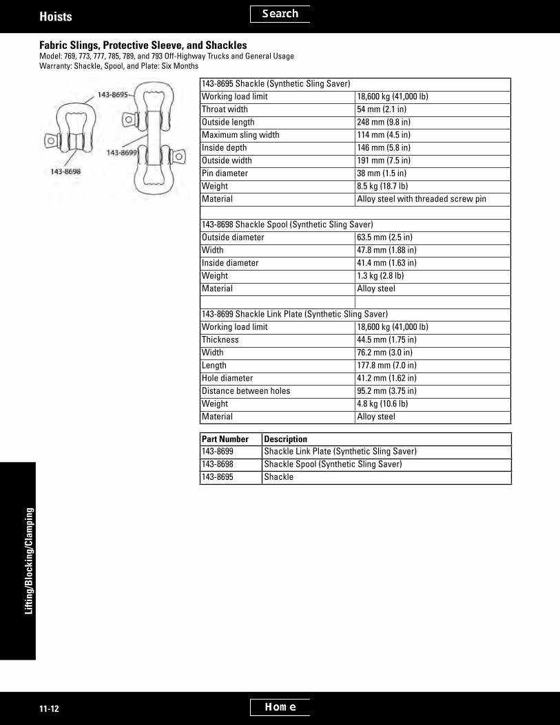
5P-3050 Crankcase and Transmission Guard JackWarranty: Six Months
• 5P-3050 Jack Group can be used for easy removal and installation of crankcase and transmission guards on any Cat® vehicle
• Attaches directly to the guard at 3 support points; when expandable arm and hook assemblies are detached, the table can be used to support smaller guards
• Also designed to allow relocation of the arm and hook assemblies or attachment of fabricated adapters for other applications
Maximum capacity:0 - 10.21 cm (0 - 4 in) lift 2,600 lb (1.3 ton)10.21 cm (4 in) to maximum lift 4,000 lb (2 ton) Overall dimensions 129.5 x 60.9 cm (51 x 24 in) Dimensions, maximum - minimum:Table height 69.8 - 22.3 cm (27.5 - 8.8 in)Hook height 142.2 - 52.0 cm (56.0 - 20.5 in)Width between hooks 132.0 - 76.2 cm (52.0 - 30.0 in)Length between supports 91.4 - 68.5 cm (36.0 - 27.0 in)
Item 1 Part Number Description-- 5P-3050 Crankcase and Transmission Guard Jack1 5P-3047 15.2 cm (6 in) Swivel Caster (2), 50.8 mm (2 in) wide2 5P-3048 15.2 cm (6 in) Rigid Caster (2), 50.8 mm (2 in) wide2 5P-3049 Jack Repair Kit (available separately)
1 Includes Item 3: Capacity Decal SEHS7448
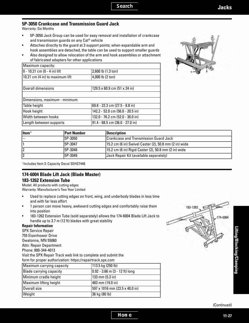
174-6004 Blade Lift Jack (Blade Master)183-1262 Extension TubeModel: All products with cutting edgesWarranty: Manufacturer’s Two Year Limited
• Used to replace cutting edges on front, wing, and underbody blades in less time and with far less effort
• 1 person can move heavy, awkward cutting edges and comfortably raise them into position
• 183-1262 Extension Tube (sold separately) allows the 174-6004 Blade Lift Jack to handle up to 3.7 m (12 ft) blades with great stability
Repair InformationSPX Service Repair 755 Eisenhower Drive Owatonna, MN 55060 Attn: Repair Department Phone: 800-344-4013 Visit the SPX Repair Track web link to complete and submit the form for proper authorization: https://repairtrack.spx.comMaximum carrying capacity 113.5 kg (250 lb)Blade carrying capacity 0.92 - 3.66 m (3 - 12 ft) longMinimum cradle height 133 mm (5.3 in)Maximum lifting height 483 mm (19.0 in)Overall size 597 x 1016 mm (23.5 x 40.0 in)Weight 36 kg (80 lb)
(Continued)

2635874
2635889
11-28
Lifti
ng/B
lock
ing/
Clam
ping
Jacks
174-6004 Blade Lift Jack (Blade Master) (Continued)183-1262 Extension TubeModel: All products with cutting edgesWarranty: Manufacturer’s Two Year Limited
Part Number Description183-1262 Extension Tube174-6004 Blade Lift Jack (Blade Master)
4C-3051 Dual Wheel DollyWarranty: Manufacturer’s Two Year Limited
• Allows one man to remove, transport and replace heavy truck dual wheel and tire assemblies without strain or struggle
• Ruggedly built unit• Handles wheels weighing up to 680 kg (1,500 lb), any tire diameter• Hydraulic jacking mechanism provides full 12.7 cm (5 in) lift; gives serviceman
fingertipcontrolwhenpositioningorloweringliftingarms• 1.83 m (6 ft) chain provided to hold wheel assembly in place during removal and
transport• Free-rolling swivel casters provide effortless maneuverabilityRepair InformationSPX Service Repair 755 Eisenhower Drive Owatonna, MN 55060 Attn: Repair Department Phone: 800-344-4013 Visit the SPX Repair Track web link to complete and submit the form for proper authorization: https://repairtrack.spx.comCapacity 680 kg (1,500 lb)Floor space 114.3 x 104.1 cm (45 x 41 in)Lift travel 12.7 cm (5 in)Tilt adjustment 2°Front caster diameter 88.9 mm (3 1/2 in)Rear caster diameter 10.1 cm (4 in)Weight 79 kg (175 lb)
Part Number Description4C-3051 Dual Wheel Dolly

2969209
2635906
2635929
11-29
Lifting/Blocking/Clam
pingJacks
380-5719 Hydraulic Service Jack, 3.5 TonWarranty: Manufacturer one year
• Replaces 1U-9744 Hydraulic Service Jack• Fast acting pump reaches lifting height in less than a pump to allow user to
reach a variety of service height situations quickly• Universal joint release mechanism• Rolledsideframesresistflexing• Lowprofiledesignallowsforeasyaccessundervehicles• Meets ANSI-PALD standards380-5719SpecificationsCapacity, tons (metric ton) 3.5 (3.2)Low Height 3.75 in (95.2 mm)Maximum Lift Height 22.0 in (558.8 mm)Net Weight 103.0 lbs (46.72 kg)Saddle Diameter 4.25 in (107.9 mm)
159-3175 Hydraulic JackWarranty: Six Months
• Replaces discontinued 5P-2385• Used for quick, easy lift truck service work• Low initial height, high lifting capacity, small size and weight• Canbeusedinshoporfieldtoliftmostlifttrucks• Folding handle (when in closed position allows jack to be carried)• HandlecanbelockedinverticalpositionformovingunitacrossfloorCapacity 3,630 kg (8,000 lb)Minimum height 57 mm (2.25 in)Maximum lift height 40.6 cm (16 in)Weight 29 kg (63 lb)Length (folded) 79 cm (31 in)Width 20 cm (8 in)Height 15.2 cm (6 in)
Part Number Description Includes159-3175 Hydraulic Jack --
Service/Repair Parts4C-9482 Seal Kit O-ring (7), Seals (2)4C-9483 Pump Kit Pump housing, O-ring, seal, plunger
Tune-up and Repair Kits for Discontinued Jacks• Tune-up kits include blades, gaskets, rings, seals, etc.• Repair kits include clutch parts plus tune-up kit parts20-Ton Jacks, 1U-6301 and 1U-5981, both discontinued 1U-5980 Pneumatic Oil Pump Tune-up Kit 50-Ton Jacks, 1U-6303 and 1U-6302, both discontinued 1U-5980 Pneumatic Oil Pump Tune-up Kit
Part Number Description1U-5980 Pneumatic Oil Pump Tune-up Kit

2635942
2635949
3052271
3052230
11-30
Lifti
ng/B
lock
ing/
Clam
ping
Stands
Stands
The following vehicle stands are designed for use in pairs and are sold separately.
5P-6215 StandWarranty: Six Months
• Designed for use in pairs — sold separately• For blocking under D3 Tractors and 931 Track-type Loaders• Can support up to 5 ton (10,000 lb) each• Adjustable from 368 mm (14.50 in) to 533 mm (21.00 in) in increments of 12.7 mm
(0.50 in)• A positive pin lock furnishes support for the load
Item Part Number Description1 1U-9583 Pin2 5P-6216 Tube Assembly3 5P-0149 Chain4 4B-4161 Screw-- 5P-6215 Stand
417-1324 Support StandWarranty: Manufacturer’s One Year
• Vehicle support stand• Sold in pairs• Tabbed bottom to provide superior stability• Pin hole design provides multiple height positionsSpecificationsCapacity 7 Tons (each)Start Height 241.3 mm (9 1/2 in)Maximum Lift Height 406.4 mm (16 in)Adjustment Increments 25.4 mm (1 in)Shipping Weight per pair 14.5 kg (32 lb)
Part Number Description417-1324 Support Stand
422-8733 Support StandWarranty: Manufacturer’s
• Vehicle support stand• Sold in pairs• Tabbed bottom to provide superior stability• Pin hole design provides multiple height positionsSpecificationsCapacity 7 Tons (each)Start Height 304.8 mm (12 in)Maximum Lift Height 508 mm (20 in)Adjustment Increments 25.4 mm (1 in)Shipping Weight per pair 17.2 kg (38 lb)
Part Number Description422-8733 Support Stand

2635968
2635990
11-31
Lifting/Blocking/Clam
pingStands
1U-7498 and 1U-7499 Heavy-Duty Support Stands, 12 TonWarranty: Six Months
• Designed for use in pairs — sold separately• Features a spun steel base which won’t dig or sink into asphalt or sand• Extension tubes included, but also available as service repair parts or to convert
a Low Boy to a High Boy or visa versa; bases are identical for both modelsNOTE:Order numbers are for individual stands. Customers desiring a pair of stands must order two.
Part Number Description Capacity Weight Reach1U-7498 “Low Boy” Stand 12 ton 15 kg (33 1/16 lb) 483 - 750 mm (19 - 29 1/2 in)1U-7499 “High Boy” Stand 12 ton 18 kg (39 11/16 lb) 857 - 1124 mm (33 3/4 - 44 1/4 in)
Extension Tubes1U-7500 For 1U-7499 “High Boy” -- 7.3 kg (16 lb) --1U-7501 For 1U-7498 “Low Boy” -- 3.9 kg (8.6 lb) --
Cat® Lift Stands, 25, 55 and 100 TonWarranty: Six Months
European Union compliant, CE marked (277-7200)Lift and support your largest equipment with these reliable lift stands designed by Caterpillar® and tested to 3 times rated capacity.• Sold individually but it is recommend they be purchased in pairs• Infinitelyvariableblockingrange• Rolls easily on smooth, hard surface — simple to move with a fork lift truck or
on attached 12.7 cm (5 in) wheels• Rugged construction of steel plate and tubing; critical parts are heat treated for
durability• Hydraulic system has 115/230 VAC single-phase 50/60 Hz motor• Hydraulic system, 277-7200, powers 2 stands at the same time for uniform lifting
and lowering• Tested to 3 times rated capacity
- exceeds requirements of ASME/ANSI PALD-4C-1991 - exceeds requirements of Australia Standard AS 2538-1985
• Combines lifting and supporting functions• Shipped assembled with 6.10 m (20 ft) hose — ready to use• Completely self storing• “Flip Over” saddle to match saddle to load point• Velocity fuse valve prevents sudden dropping of load if pressure loss occursReferencesNEHS0603, Lift Stand Tool Operating Manual for Service/Repair Parts NEHS0943, Hydraulic Pump Group
(Continued)

2635990
2979558
2636019
11-32
Lifti
ng/B
lock
ing/
Clam
ping
Stands
Cat® Lift Stands, 25, 55 and 100 Ton (Continued)Warranty: Six Months
Item Part Number DescriptionRated Capacity
Min. Height
Max. Height
Usable Stroke kPa psi
Cylinder effective area
Approx. Weight
Base Contact Area
Cat Lift Stands (pictured in pairs, back to front)1 9U-7489 Lift Stand, 100
Ton90,800 kg (100 ton)
634 mm (25.87 in)
1600 mm (62.97 in)
241 mm (9.5 in)
66,798 9695 133 cm² (20.63 in²)
390 kg (860 lb)
898 cm² (139.2 in²)
2 9U-7536 Lift Stand, 55 Ton
49,940 kg (55 ton)
660 mm (26.0 in)
1613 mm (63.5 in)
318 mm (12.5 in)
68,590 9955 71 cm² (11.05 in²)
277 kg (610 lb)
898 cm² (139.2 in²)
3 9U-7540 Lift Stand, 25 Ton
22,700 kg (25 ton)
597 mm (23.5 in)
1626 mm (64.0 in)
286 mm (11.25 in)
66,830 9700 33 cm² (5.15 in²)
151 kg (333 lb)
898 cm² (139.2 in²)
4 277-7200 Hydraulic Pump with 4C-5749 Dolly (optional)
-- -- -- -- -- -- -- -- --
372-5264 Undecking ToolModel Usage: CT660 TruckWarranty: Manufacturer’s
• Used to assure safe and non-destructive undecking of vehicles.SpecificationsDimensions 1048 x 630 x 269 mmWeight 41.3 kg
Part Number Description372-5264 Undecking Tool
Cat® Tube Stand Groups, 12, 20, and 25 Ton CapacityEssential ToolModel: AllWarranty: Six Months
TUV marked• Used to support (block) track-type or rubber tired vehicles• Tube stand capacity is rated in US tons, not metric tons• Used with separate lifting device or hydraulic jacks• Designed to be used in pairs• Rugged heavy-duty design with welded, all steel construction• Meets stability standards and load capacity for AS/NZS 2538:2004, ANSI, PALD,
and TUV• Dual lock-pin design provides 2 load-bearing surfaces• Adjustable height in 19 mm (0.75 in) increments• 20 and 25 ton tube stand bases feature retractable spring-loaded castersReferencesNEHS0967, 286-7889 Jack Stand Group, 12 Ton Capacity NEHS0938, 283-1495 and 284-5122 Tube Stand Groups, 20 and 25 Ton Capacity
(Continued)

2636019
2694412
2694448
11-33
Lifting/Blocking/Clam
pingStands
Cat® Tube Stand Groups, 12, 20, and 25 Ton Capacity (Continued)Essential ToolModel: AllWarranty: Six Months
Part Number Rated Capacity Minimum Height Maximum Height Base Contact Diameter286-7889 10,886 kg (23,999 lb) 43.2 cm (17.0 in) 72.0 cm (28.3 in) 111.3 cm (43.8
in) medium tube46.2 cm (18.2 in)
283-1495 18,144 kg (40,001 lb) 59.9 cm (23.6 in) short tube; 86.6 cm (34.1 in) medium tube 1
84.7 cm (33.3 in) short tube; 111.3 cm (43.8 in) medium tube 1
65 cm (25.6 in)
284-5122 22,680 kg (50,001 lb) 81.0 cm (31.8 in) short tube; 107.7 cm (42.4 in) medium tube; 125.9 cm (49.5 in) long tube 1
105.7 cm (41.6 in) short tube; 132.5 cm (52.1 in) medium tube; 171.6 cm (67.5 in) long tube 1
91.5 cm (36 in)
1 Optional 283-1498 Saddle adds 44 mm (1.7 in) to height when installed
Service/Repair Parts for 286-7889 Jack Stand Group - 12 Ton (US) Capacity
Item Part Number DescriptionService/Repair Parts for 286-7889 Jack Stand Group - 12 Ton (US) Capacity
1 286-7892 Base2 286-7895 Tube3 286-7896 Lock-Pin4 4C-6709 Lanyard-- 286-8090 Film Group
Service/Repair Parts for 283-1495 Tube Stand Group - 20 Ton (US) Capacity
Item Part Number Description DetailService/Repair Parts for 283-1495 Tube Stand Group - 20 Ton (US) Capacity
1 283-1470 Base --2 283-1478 Tube, 594 mm (23.4 in) --3 283-1500 Lock-Pin --4 4C-6709 Lanyard ---- 287-2094 Film Group --
Optional Items5 283-1482 Tube, 84.1 cm (33.1 in) Increases height capability of tube stand6 283-1498 Saddle Fits over tube and locates load on center of tube stand (adds 44 mm
[1.7 in] to height)7 277-7195 Handle Attaches for quick and easy positioning of tube stands

2695851
11-34
Lifti
ng/B
lock
ing/
Clam
ping
Stands
Service/Repair Parts for 284-5122 Tube Stand Group - 25 Ton (US) Capacity
Item Part Number Description DetailService/Repair Parts for 284-5122 Tube Stand Group - 25 Ton (US) Capacity
1 283-1480 Base --2 283-1478 Tube, 594 mm (23.4 in) --3 283-1500 Lock-Pin --4 4C-6709 Lanyard --
Optional Items5 283-1482 Tube, 84.1 cm (33.1 in) Increases height capability of tube stand6 283-1493 Tube, 128.0 cm (50.4 in) Increases height capability of tube stand6 283-1498 Saddle Fits over tube and locates load on center of tube stand (adds 44 mm
[1.7 in] to height)7 277-7195 Handle Attaches for quick and easy positioning of tube stands
! WARNING
Do not use 283-1493 Long Tube with 283-1470 Base. This combination of parts can result in an unstable load, which could cause serious injury or death.
Tube StandsWarranty: Six Months
• Usedtoliftandblocktrack-typeorrubbertiredvehicleswithintheirspecifiedcapacities
• Can also be used with the 9S-0019 Tractor Lifts for blocking after the lifts have raised the tractor
• Chart lists the proper selection of tools that will provide a lifting range from 32.39 to 212.73 cm(12.75 to 83.75 in); lifting capacity is 20 tons for each stand and 25 tons for each cylinder and base combination — using a suitable hydraulic pumpwiththesetools,itispossibletoliftandblockmostvehiclesinaboutfiveminutes)
• Hydraulicpumpsthatwillefficientlyoperatethesetoolsmusthaveamaximumoutput pressure of 69,000 kPa (10,000 psi)
Lifting Only Tool HeightBlocking Only Tool
HeightLifting and Blocking
Tool Height
Item Part No. Description
32.4 - 69.9 cm (12.75 -27.5 in)
51.4 - 88.9 cm (20.25 - 35.0 in)
49.5 - 77.5 cm (19.50 - 30.5 in)
74.9 - 101.6 cm (29.48 - 40.0 in)
85.1 - 137.8 cm (33.50 - 54.25 in)
121.9 - 174.6 cm (48.00 - 68.75 in)
160.0 - 212.7 cm (63.00 - 83.75 in)
1 8S-7641 Tube -- -- -- -- -- -- 12 4C-6486 Stand 1 -- -- -- 1 1 1 13 8S-7631 Tube -- -- -- -- -- 1 --4 8S-7640 Stand 2 -- -- 1 -- -- -- --5 8S-7621 Tube -- -- -- -- 1 -- --6 8S-7620 Base As-
sembly-- 1 -- -- -- -- --
(Continued)

2636054
2694591
11-35
Lifting/Blocking/Clam
pingStands
Tube Stands (Continued)Warranty: Six Months
Lifting Only Tool HeightBlocking Only Tool
HeightLifting and Blocking
Tool Height
Item Part No. Description
32.4 - 69.9 cm (12.75 -27.5 in)
51.4 - 88.9 cm (20.25 - 35.0 in)
49.5 - 77.5 cm (19.50 - 30.5 in)
74.9 - 101.6 cm (29.48 - 40.0 in)
85.1 - 137.8 cm (33.50 - 54.25 in)
121.9 - 174.6 cm (48.00 - 68.75 in)
160.0 - 212.7 cm (63.00 - 83.75 in)
7 8S-7610 Base As-sembly
1 -- -- -- -- -- --
8 8S-7611 Tube -- -- 1 1 -- -- --9 396-9840 Cylinder 1 3 1 3 -- -- 1 4 1 4 1 4
10 8S-7625 Collar -- -- -- -- 1 1 111 8S-8048 Saddle -- -- 1 5 1 5 1 5 1 5 1 5
12 8S-7615 Pin -- -- 1 1 2 2 213 8S-7645 Hose Group 1 6 1 6 -- -- -- -- --
Not Shown6 1S-8937 Valve -
Needle1 -- -- 1 1 1 --
-- 4C-6562 Double Pin Assem-bly with Lanyard (used with 4C-6486 Stand)
-- -- -- -- -- -- --
-- 9S-1557 Saddle 1 3 1 3 -- -- 1 4 1 4 1 4
1 Includes: NEEG2453 Warning Decal and NEEG2001 Cat® Logo Decal2 Includes: NEEG2025 Warning Decal3 Lifting capacity of 396-9840 Cylinder used with the 8S-7620 or 8S-7610 Base Assembly is 25 ton (50,000 lb at 10,000 psi).4 Lifting capacity of 396-9840 Cylinder with offset 8S-7640 Stand is 20 ton (40,000 lb at 10,000 psi).5 Saddle (8S-8048) is used for lifting against convex surfaces.6 Hose (8S-7645) required if two cylinders are used with one pump.
Specifications for all Pumps for Use on Double and Single Acting Hydraulic Cylinders (396-9840)Electric Operated Pumps
Oil Delivery (cu in/min)Part Number Voltage
Line Fre-quency
Reservoir Capacity Motor HP
Maximum Pressure 100 psi 1,000 psi 5,000 psi
10,000 Valve Control
2P-5500 230 50-60 1.70 L (0.45 gal)
1/2 69,000 kPa (10,000 psi)
170 32 25 18 3-Position
2P-5550 115 50-60 1.70 L (0.45 gal)
1/2 69,000 kPa (10,000 psi)
-- -- -- -- --
1U-7520 115 50-60 7.57 L (2.0 gal)
1/2 69,000 kPa (10,000 psi)
-- -- -- -- 4-Way
3S-6224 115 50-60 7.57 L (2.0 gal)
1 1/8 69,000 kPa (10,000 psi)
-- -- -- -- Manual
8S-8033 230 50-60 7.57 L (2.0 gal)
1 1/8 69,000 kPa (10,000 psi)
650 80 70 55 --
1U-5555 115 60 7.57 L (2.0 gal)
1 1/2 69,000 kPa (10,000 psi)
-- -- -- -- --
1U-5565 230 50 7.57 L (2.0 gal)
1 1/2 69,000 kPa (10,000 psi)
425 45 45 45 4-Way
(Continued)

2694591
2694608
2695481
2694571
11-36
Lifti
ng/B
lock
ing/
Clam
ping
Stands
Specifications for all Pumps for Use on Double and Single Acting Hydraulic Cylinders (396-9840) (Contin-ued)Electric Operated Pumps
Oil Delivery (cu in/min)Part Number Voltage
Line Fre-quency
Reservoir Capacity Motor HP
Maximum Pressure 100 psi 1,000 psi 5,000 psi
10,000 Valve Control
4C-5080 230 60 7.57 L (2.0 gal)
1 1/2 69,000 kPa (10,000 psi)
425 45 45 45 Solenoid
Specifications for all Pumps for Use on Double and Single Acting Hydraulic Cylinders (396-9840)Air Operated Pumps
Oil Delivery (cu in/min)
Part Number Air Requirement Reservoir CapacityMotor HP
Maximum Pressure PSI 0 psi 5,000 PSI 10,000 PSI
Control Value
1U-7522 50 cfm at (80 psi) 7.57 L (2.0 gal) 3 69,000 kPa (10,008 psi)
465 50 25 3-Position 4-Way
Specifications for all Pumps for Use on Double and Single Acting Hydraulic Cylinders (396-9840)Hand Pumps
Pump Part NumberReservoir Capacity
Maximum Pressure at 1st Stage and 2nd Stage Volume Per Stroke Control Value For Use With:
1U-7544 140 cu in 1st Stage, 2069 kPa (300 psi) - 2nd Stage, 69,000 kPa (10,000 psi)
38.51 cc (2.35 cu in) - 2.41 cc (0.147 cu in)
Built in - 2-Way Single Acting Rams
1U-5230 55 cu in 69,000 kPa (10,000 psi) 2.62 cc (0.160 cu in) -- Single Acting Rams
FT0890 Tube Holder• Used to safely store and move the tubes for the 4C-6489 and the 8S-7640 Jack-
stands• Fabricate an FT0890 Tube Holder and attach it to the 8S-9901 Tool Cart

2636069
2636089
2636107
11-37
Lifting/Blocking/Clam
pingStands
1U-7502 Heavy Duty Repair Stand, 907 kg (2,000 lb)Warranty: Six Months
• Adjustable universal mounting arms (4) enable you to mount an endless variety of engines, transmissions, torque converters, rear axles and other components, without special adapters being necessary.
• Component solidly cradled in stand, supported from both sides, just as it is in vehicle
• Twin-post design, featuring laterally-adjustable outboard support, provides extremely stable workholding unit
• Gearbox allows full rotation of mounted unit for service, with just a turn of the crank — locks in position
• Mounted on wheels and casters, can be easily maneuvered from storage to work area
• Locking rear wheels anchor the stand at the desired work locations
Part No. Description Capacity Weight1U-7502 Heavy Duty Repair Stand, 907 kg (2,000 lb) 907 kg
(2,000 lb)127 kg (280 lb)
178-8906 Transmission BracketModel: 950 Wheel LoaderWarranty: Six Months
• Used to mount constant mesh countershaft transmissions• Used with 1U-7502 Heavy Duty Repair Stand, 907 kg (2,000 lb)• Transmission can be rotated 180 degrees for complete disassembly and repair
Part Number Description1U-7502 Heavy Duty Repair Stand, 907 kg (2,000 lb)178-8906 Transmission Bracket
1U-7506 Transmission Adapter KitWarranty: Six Months
• Complete with mounting hardware for use on 1U-9352 and 1U-7502 Engine Stands• Converts your engine stand into a transmission service stand in a matter of minutes• Replaces the adjustable arms of the stand to hold and position the transmission for repair or overhaul• Transmission is held at workbench height with 3 sides fully exposed for working convenience; and it can be rotated a full
360° for complete access to all parts• Weight: 4.65 kg (10 lb, 4 oz)
Part Number Description1U-7506 Transmission Adapter Kit

2636123
11-38
Lifti
ng/B
lock
ing/
Clam
ping
Stands
319-1845 Phase Module Lifting DeviceEssential ToolModel: 795F AC Off-Highway TruckWarranty: Six Months
European Union compliant, CE marked• Used to remove and install various invertor cabinet component
– DC Power Bus Capacitor – Retarding Contactor Tray Assembly – Phase Module
• Used with a suitable overhead lifting device• Lifting point turnbuckle allows small height adjustments to align tooling with
invertor cabinet compartment• Alignment plate secures lower tray to invertor cabinet• Sliding brackets and threaded holes provide a method of securing components
to the lower tray during removal and installation (includes required hardware, stored on the tooling)
• Lower tray has UHMW pads to allow components to easily slide in and out of invertor cabinet
• Lower tray is designed to separate from tooling to allow phase module to be lifted out of or lowered into shipping container
ReferenceKENR8715, 795F AC Off-Highway Truck, Power Train, Disassembly and AssemblyNEHS1078, Tool Operating Manual, 319-1845 Phase Module Removal Tool
Part Number Description319-1845 Phase Module Lifting Device

2636221
2636238
11-39
Lifting/Blocking/Clam
pingMiscellaneous
Miscellaneous
Tractor LiftWarranty: Six Months
• Using the tractor lifts illustrated, any track-type vehicle can be raised and blocked by 2 men in 3 to 5 minutes
• Each tractor lift has a curved base 30.48 cm (12 in) wide and has 45.72 cm (18 in) radiuswhichrollseasilyonanyconcretefloor
• Tractor lift consists of four 9S-0027 Lift AssembliesAlso Includes:Item Description Quantity2 Wheel 2
Item Part Number Description Capacity Quantity1 9S-0027 Lift Assembly 30 ton 4
1U-9724 Columbus-McKinnon Drop Forged Load Binder (Overcenter)Warranty: Manufacturer’s One Year Against Defects In Materials And Workmanship
• All steel• Drop forged• 360° swivel• Each binder individually proof tested• Short reach for maximum take-up• Tie-down hole in handle• Special manufacturing permits use with transport grade 70 chainRepair InformationColumbus-McKinnon Audubon and Sylan Parkway Amherst, NY 14228Phone: (800) 888-0985 Fax: (716) 689-5644 Web site: www.cmindustrial.com
Cat Part Number
Supplier Part Number Description Working Load Limit Chain Size Take-up Net Weight
1U-9724 320105 Overcenter Load Binder 2,449 kg (5,400 lb) 7.93 mm (5/16 in) Grade 70, 9.52 mm (3/8 in) Grade 43
10.8 cm (4.25 in) 3.62 kg (8 lb)
! WARNING
Serious damage to a chain may occur when a force exceeding the maximum working load limit is applied to a chain assembly. The maximum working load limits are not to be exceeded.

2990964
11-40
Lifti
ng/B
lock
ing/
Clam
ping
Miscellaneous
Lever HoistsModel Usage: All modelsWarranty: Manufacturer’s Five Year
European Union compliant, CE marked• Capacities from 3/4 to 6 tons• Impact resistant, stamped steel frame, gear case and cover for durability and
light weight• Powdercoatedfinishforaddedcorrosionprotection• Hardened steel load sharing gears• Double pawl arrangement for assured load control• Two chain guide rollers for positive chain• Weston type braking system for positive load control and positioning• Simple one-handed, free chaining for fast load attachment• Hardened steel chain for strength and long wear life• Forged upper and lower hooks with heavy cast steel latches• Rubber handle grip for added operator comfort• Minimal maintenance with the special tools required• Metric rated• Meets ASME B30.21 – Manually Lever Operated Hoist StandardRepair InformationColumbus-McKinnon Audubon and Sylan Parkway Amherst, NY 14228 Phone: (800) 888-0985 Fax: (716) 689-5644 Web Site: www.cmindustrial.com
Lever Hoists
Part NumberMax. Rated Capacity Standard Lift
Pull to Lift Load Shipping Weight
Min. Distance Between Breaks Handle Length
Hook Throat Opening
386-6030 3/4 Ton 1 1.5 m (4.99 ft) 15 kg (33.07 lb)
9.1 kg (20 lb) 32.0 cm (12 19/32 in)
28.0 cm (11 in) 28.6 mm (1 1/8 in)
386-6031 3/4 Ton 1 3 m (9.97 ft) 15 kg (33.07 lb)
9.1 kg (20 lb) 32.0 cm (12 19/32 in)
28.0 cm (11 in) 28.6 mm (1 1/8 in)
386-6032 1 1/2 Ton 1 1.5 m (4.99 ft) 23.1 kg (50.93 lb)
13.6 kg (29.98 lb) 37.8 cm (14 7/8 in) 41.3 cm (16.25 in) 31.8 mm (1 1/4 in)
386-6033 1 1/2 Ton 1 3 m (9.97 ft) 23.1 kg (50.93 lb)
15.4 kg (33.95 lb) 37.8 cm (14 7/8 in) 41.3 cm (16.25 in) 31.8 mm (1 1/4 in)
386-6034 3 Ton 1 1.5 m (4.99 ft) 35 kg (77.16 lb)
29.5 kg (65.04 lb) 47.7 cm (18 25/32 in)
41.3 cm (16.25 in) 39.7 mm (1 9/16 in)
386-6035 3 Ton 1 3 m (9.97 ft) 35 kg (77.16 lb)
29.5 kg (65.04 lb) 47.7 cm (18 25/32 in)
41.3 cm (16.25 in) 39.7 mm (1 9/16 in)
386-6036 6 Ton 2 1.5 m (4.99 ft) 35 kg (77.16 lb)
35 kg (77.16 lb) 59.0 cm (23 15/64 in)
41.3 cm (16.25 in) 55.6 mm (2 3/16 in)
1 1 chain strand2 2 chain strands
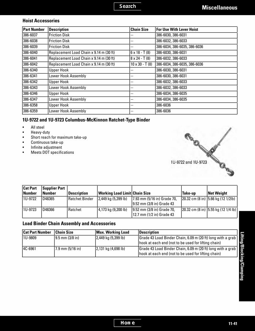
2991011
2694176
2696700
11-41
Lifting/Blocking/Clam
pingMiscellaneous
Hoist Accessories
Part Number Description Chain Size For Use With Lever Hoist386-6037 Friction Disk -- 386-6030, 386-6031386-6038 Friction Disk -- 386-6032, 386-6033386-6039 Friction Disk -- 386-6034, 386-6035, 386-6036386-6040 Replacement Load Chain x 9.14 m (30 ft) 6 x 18 - T (8) 386-6030, 386-6031386-6041 Replacement Load Chain x 9.14 m (30 ft) 8 x 24 - T (8) 386-6032, 386-6033386-6042 Replacement Load Chain x 9.14 m (30 ft) 10 x 30 - T (8) 386-6034, 386-6035, 386-6036386-6340 Upper Hook -- 386-6030, 386-6031386-6341 Lower Hook Assembly -- 386-6030, 386-6031386-6342 Upper Hook -- 386-6032, 386-6033386-6343 Lower Hook Assembly -- 386-6032, 386-6033386-6346 Upper Hook -- 386-6034, 386-6035386-6347 Lower Hook Assembly -- 386-6034, 386-6035386-6358 Upper Hook -- 386-6036386-6359 Lower Hook Assembly -- 386-6036
1U-9722 and 1U-9723 Columbus-McKinnon Ratchet-Type Binder• All steel• Heavy-duty• Short reach for maximum take-up• Continuous take-up• Infiniteadjustment• MeetsDOTspecifications
Cat Part Number
Supplier Part Number Description Working Load Limit Chain Size Take-up Net Weight
1U-9722 D48365 Ratchet Binder 2,449 kg (5,399 lb) 7.93 mm (5/16 in) Grade 70, 9.52 mm (3/8 in) Grade 43
20.32 cm (8 in) 5.66 kg (12 1/2lb)
1U-9723 D48366 Ratchet 4,173 kg (9,200 lb) 9.52 mm (3/8 in) Grade 70, 12.7 mm (1/2 in) Grade 43
20.32 cm (8 in) 5.55 kg (12 1/4 lb)
Load Binder Chain Assembly and Accessories
Cat Part Number Chain Size Max. Working Load Description1U-9809 9.5 mm (3/8 in) 2,449 kg (5,399 lb) Grade 43 Load Binder Chain, 6.09 m (20 ft) long with a grab
hook at each end (not to be used for lifting chain)4C-6961 7.9 mm (5/16 in) 2,131 kg (4,698 lb) Grade 43 Load Binder Chain, 6.09 m (20 ft) long with a grab
hook at each end (not to be used for lifting chain)

2636297
2979546
2636343
11-42
Lifti
ng/B
lock
ing/
Clam
ping
Miscellaneous
8S-9906 Ratchet Puller5P-9694 Ratchet PullerWarranty: Six Months
• Used for many pulling operations within their capability• Capacities are given below
Part No. Description Lifting CapacitySingle line capacity
Double line capacity
8S-9906 Ratchet Puller (used with track tool cart)8S-9906 Ratchet As - Puller 510 - 453 kg (1125 - 1000 lb) -- --
5P-9694 Ratchet Puller5P-9694 Hoist - Rachet -- 771 kg
(1,700 lb)1,542 kg (3,400 lb)
372-5261 Steering Wheel PullerModel Usage: CT660 TruckWarranty: Manufacturer’s
• Used to properly remove steering wheel during serviceSpecificationsDimensions 5.4 x 4.3 x 3.2 inWeight 1 kg
Part Number Description372-5261 Steering Wheel Puller
FT2977 Skid Plate AssemblyEssential ToolModel: RM350B and other Road ReclaimersWarranty: None
• Provides an alternative method of removing rotor chamber• Skid plate prevents damage as component is removed from machineReferenceKENR3127, RM350B Disassembly and Assembly Manual

2636354
2848782
11-43
Lifting/Blocking/Clam
pingMiscellaneous
FT0600 Cable Saver BlocksWarranty: None
• Used for cable-lifting any square section item• Will accommodate any size cable and protect it from damage on sharp corners
376-4554 Truck Body Lifting Pin376-4556 Truck Body Lifting PinModel: All Off-Highway TrucksWarranty: Six Months
CE Compliant• Used to remove and install truck bodies on Off-Highway Trucks• Available as individual groups• 376-4554 used on 785, 789, 793, 795, 797• 376-4556 used on 770 (formerly the 769), 772 (formerly the 771), 773, 775, 777• Groups consist of 4 pins and 4 shackles• Pins available separately
376-4553 long replacement pin 376-4555 short replacement pin
ReferenceNEHS1120, Tool Operating Manual376-4554 Truck Body Lifting PinWorking Load Limit 18000 kg (39683.16 lb)Weight (individual) 48.65 kg (107.25 lb)Weight (group) 194.6 kg (429 lb)Dimensions 510.9 x 127 mm (20.11 x 5 in) 376-4556 Truck Body Lifting PinWorking load Limit 7000 kg (15432.34 lb)Weight (individual) 21.61 kg (47.64 lb)Weight (group) 86.44 kg (190.5 lb)Dimensions 314.9 x 127 mm (12.39 x 5 in)
Part Number Description376-4554 Truck Body Lifting Pin376-4556 Truck Body Lifting Pin

2636364
3038033
11-44
Lifti
ng/B
lock
ing/
Clam
ping
Miscellaneous
260-9412 Lift Chain AssemblyModel: Track-Type MachinesWarranty: Six Months
European Union compliant, CE marked• Used to remove, install, and position track segments on track-type machines• Used with suitable overhead lifting device• Clamping shoes provide a quick, secure method of attaching to track segments• Large master link joins two lengths of Grade 80 chain and provides attachment
point for lifting device• VersatiledesignfitsawiderangeoftracksegmentswithvariouswidthsReferenceNEHS1077, Tool Operating Manual, 260-9412 Lift ChainWorking load limit 454 kg (1,000 lb)Approximate length 922.5 mm (36.0 in)¹Weight 5.9 kg (13 lb)Master link 65.3 mm (2.57 in) wide opening with 12.7
mm (.50 in) diameter steelClamping shoe maximum jaw opening - 25.4 mm (1.0 in)
jaw depth - 90 mm (3.6 in)¹ Varies with chain angle (spread).
Part Number Description260-9412 Lift Chain Assembly
207-0755 Lifting Plate, 207-0756 Lift Chain AssemblyModel Usage: D6R, D6TWarranty: Six Months
European Union Compliant, CE marked• Used to safely remove and install C9 engines from machine• Connects correctly and easily to engine and lifting device• Use 207-0756 with 142-6893 adjustable C-hook and 207-0755 Lifter PlateReferenceNEHS1094, Tool Operating ManualRENR8175, D6R Series III and D6T Track-Type Tractors Engine SupplementRENR4253, D6R Series II Track-Type Tractor C9 Engine SupplementKENR8563, D6R Track-Type Track Engine SupplementSpecifications 207-0755 207-0756Working Load Limit 1588 kg (3500 lb) 5443 kg (12,000 lb)Material Durable Steel Grade 800 Steel Chain
Part Number Description207-0755 Lifting Plate207-0756 Lift Chain Assembly
Serviceable Part(s)1U-9793 Hook

2636383
2636405
3044592
11-45
Lifting/Blocking/Clam
pingMiscellaneous
328-1720 Tube Assembly, 329-1968 AdapterEssential ToolModel: SR4, SR5, and C175-16 GeneratorsWarranty: Six Months
• Used to remove and install rotor assembly with generator in horizontal position• Lengthof328-1720TubeAssembly(2083mm[82in])providesleveragetofloat
rotor assembly in or out of generator• 328-1720TubeAssemblyhasbrassadapterthatdirectlyfitsSR4andSR5gen-
erator rotor shaft• 4 set screws on 328-1720 Tube Assembly lock tool onto SR4 and SR5 rotor shaft
or 329-1968 Adapter• Brass adapter must be removed from 328-1720 Tube Assembly for use with 329-
1968 Adapter and C175-16 generator rotor shaft
Part Number Description328-1720 Tube Assembly329-1968 Adapter
Service/Repair Parts9F-6641 Bolt
330-9910 AdapterEssential ToolModel: C175 1800 Frame GeneratorsWarranty: Six Months
• Used to remove and install rotor assembly with generator in horizontal position• Used with 328-1720 Tube Assembly (sold separately)• Four bolts and brass adapter must be removed from 328-1720 Tube Assembly
before attaching 330-9910 Adapter• 330-9910 Adapter is inserted into 328-1720 Tube Assembly• Four set screws on 328-1720 engage grooves in 330-9910 Adapter to lock it in
position
Part Number Description330-9910 Adapter
420-5317 Crib Tool421-6081 WedgeModel Usage: AllWarranty: Six Months
• 420-5317 used to build super solid stable box crib• 421-6081usedtofillgapsbetweentheloadandcribbing• Includes stepped top surfaces, sloped downward for extra gripping power• Dual surface for cribbing (Pyramid surface and Lincoln log surfaces)• Stronger, cleaner and safer than wood• No-splitting, recycled materials• Equipped with handling ropes• Colored black
(Continued)

3044592
3038258
11-46
Lifti
ng/B
lock
ing/
Clam
ping
Miscellaneous
420-5317 Crib Tool (Continued)421-6081 WedgeModel Usage: AllWarranty: Six Months
SpecificationsPart Number Dimensions Weight420-5317 152.4 x 152.4 x 914.4 mm (6
x 6x 36 in*)17.24 kg (38 lb)
421-6081 152.4 x 203.2 x 609.6 mm (6 x 8 x 24 in*)
12.25 kg (27 lb)
* Lumber sizes
Lifting Eyebolt AssemblyModel Usage: AllWarranty: Six Months
European Union Compliant, CE marked• Used to lift basic components using threaded holes• Star Shaped• WLLclearlyidentifiedinMetricTonnesandpounds• WLL is de-rated at a 90 degree pull• Eyebolt is adjustable 360 degrees• Locking device allows for tightening by hand• Powder Coating permanently changes color to beige to brown to black, if exces-
sive heat is applied - Do not use, if powder coating is beige, brown, or black.• Surface Pink Powder Coating
Working LoadPart Number Thread Size Vertical At 90 Degree Weight395-1099 3/8 - 16 UNC 1000 kg (2205 lbs) 400 kg (882 lbs) .12 kg (0.26 lb)395-1094 1/2 - 13 UNC 2000 kg (4409 lbs) 750 kg (1653 lbs) .22 kg (0.48 lb)395-1100 5/8 - 11 UNC 4000 kg (8818 lbs) 1500 kg (3307 lbs) .33 kg (0.73 lb)395-1098 3/4 - 10 UNC 6000 kg (13228 lbs) 2300 kg (5071 lbs) .54 kg (1.19 lb)395-1101 7/8 - 9 UNC 6000 kg (13228 lbs) 2300 kg (5071 lbs) .64 kg (1.41 lb)395-1096 1 - 8 UNC 8000 kg (17637 lbs) 3200 kg (7055 lbs) .98 kg (2.16 lb)421-5660 M8 -- -- 0.12 kg (0.26 lbs)395-1093 1 1/4 - 7 UNC 12000 kg (26455 lbs) 4500 kg (9921 lbs) 1.82 kg (4.01 lb)395-1092 1 1/2 - 6 UNC 16000 kg (35274 lbs) 7000 kg (15432 lbs) 3.60 kg (7.94 lb)395-1095 1 3/4 - 5 UNC 24000 kg (52911 lbs) 9000 kg (19842 lbs) 4.95 kg (10.91 lb)395-1097 2 - 4.5 UNC 32000 kg (70548 lbs) 12000 kg (26455 lbs) 7.60 kg (16.75 lb)

3045891
3038271
11-47
Lifting/Blocking/Clam
pingMiscellaneous
Lifting Eyebolt Assembly
Working LoadPart Number Size Vertical at 90 Degree Weight421-5660 M8 1000 kg (2205 lbs) 400 kg (882 lbs) 0.12 kg (0.26 lbs)421-5661 M10 1000 kg (2205 lbs) 400 kg (882 lbs) 0.12 kg (0.26 lbs)421-5662 M12 2000 kg (4409 lbs) 750 kg (1653 lbs) 0.20 kg (0.44 lbs)421-5663 M16 4000 kg (8818 lbs) 1500 kg (3307 lbs) 0.30 kg (0.66 lbs)421-5664 M18 4000 kg (8818 lbs) 1500 kg (3307 lbs) 0.30 kg (0.66 lbs)369-5916 M20 6000 kg (13228 lbs) 2300 kg (5071 lbs) 0.50 kg (1.10 lbs)421-5665 M24 8000 kg (17637 lbs) 3200 kg (7055 lbs) 0.80 kg (1.76 lbs)421-5666 M30 12000 kg (26455 lbs) 4500 kg (9921 lbs) 1.60 kg (3.53 lbs)421-5667 M36 16000 kg (35274 lbs) 7000 kg (15432 lbs) 3.50 kg (7.72 lbs)421-5668 M42 24000 kg (52911 lbs) 9000 kg (19842 lbs) 4.90 kg (10.80 lbs)421-5669 M48 32000 kg (70548 lbs) 12000 kg (26455 lbs) 7.00 kg (15.43 lbs)
Load Ring AssembliesModel Usage: AllWarranty: Six Months
European Union Compliant, CE marked• Used to lift basic components using threaded holes• Load Ring will rotate 360°• WLLclearlyidentifiedinMetricTonnes• Adjustable in pull direction• Load ring foldable• Powder Coating permanently changes color to beige to brown to black, if exces-
sive heat is applied - Do not use, if powder coating is beige, brown, or black.• Surface Pink Powder Coated
Part Number Thread Size Working Load Weight395-1590 1/2 - 13 UNC 1000 kg (2204.6 lb) .33 kg (0.73 lb)395-1591 5/8 - 11 UNC 1500 kg (3306.9 lb) .55 kg (1.21 lb)395-1592 3/4 - 10 UNC 2500 kg (5511.6 lb) 1.3 kg (2.87 lb)395-1593 7/8 - 9 UNC 2500 kg (5511.6 lb) 1.3 kg (2.87 lb)395-1594 1 - 8 UNC 4000 kg (8818.5 lb) 1.5 kg (3.31 lb)395-1595 1 1/4 - 8 UNC 5000 kg (11023.0 lb) 3.33 kg (7.34 lb)

3046051
3054931
11-48
Lifti
ng/B
lock
ing/
Clam
ping
Miscellaneous
Load Ring Assemblies
Working LoadPart Num-ber Size Vertical at 90 Degree Weight422-5471 M8 300 kg (661 lbs) 300 kg (661 lbs) 0.30 kg (0.66 lbs)422-1780 M8 1 300 kg (661 lbs) 300 kg (661 lbs) 0.10 kg (0.22 lbs)422-5472 M10 630 kg (1389 lbs) 630 kg (1389 lbs) 0.32 kg (0.71 lbs)422-1781 M10 1 630 kg (1389 lbs) 630 kg (1389 lbs) 0.10 kg (0.22 lbs)422-5473 M12 1000 kg (2205 lbs) 1000 kg (2205 lbs) 0.33 kg (0.73 lbs)422-1782 M12 1 1000 kg (2205 lbs) 1000 kg (2205 lbs) 0.10 kg (0.22 lbs)422-5474 M16 1500 kg (3307 lbs) 1500 kg (3307 lbs) 0.55 kg (1.21 lbs)422-1783 M16 1 1500 kg (3307 lbs) 1500 kg (3307 lbs) 0.10 kg (0.22 lbs)422-5475 M20 2500 kg (5291 lbs) 2500 kg (5291 lbs) 1.30 kg (2.87 lbs)422-1784 M20 1 2500 kg (5291 lbs) 2500 kg (5291 lbs) 0.10 kg (0.22 lbs)422-5476 M24 4000 kg (8818 lbs) 4000 kg (8818 lbs) 1.50 kg (3.31 lbs)422-1785 M24 1 4000 kg (8818 lbs) 4000 kg (8818 lbs) 0.10 kg (0.22 lbs)422-5477 M30 5000 kg (11023 lbs) 5000 kg (11023 lbs) 3.30 kg (1.76 lbs)
1 Max Bolt Length plus washer and nut. Clearance hole applications.
385-1152 Rear Suspension Lifting DeviceModel Usage: 793 OHT’sWarranty: Six Months
European Union Compliant, CE marked• Used to safely remove and install the rear suspension cylinders on the OHT’s• Includes ratchet strap that securely fasten rear suspension cylinder to toolReferenceNEHS1147 Tool Operating ManualSpecificationsDimensions 1875.47 x 768.9 x 460 mm (73.8 x 30.3 x
18.1 in)Weight 88.9 kg (196 lb)Working Load Limit 907.2 kg (2000 lb)
Related Documents