11. CHEMICAL RECOVERY CYCLE Table of content CHEMICAL RECOVERY CYCLE .................................................................................................................................. 1 EVAPORATION OF BLACK LIQUOR ............................................................................................................................ 1 Black liquor properties ....................................................................................................................................... 2 Terminology used in the evaporation of black liquors ....................................................................................... 4 Evaporation process ........................................................................................................................................... 8 RECOVERY BOILER................................................................................................................................................. 11 Combustion of black liquor .............................................................................................................................. 13 Recovery of heat in the recovery boiler ............................................................................................................ 16 Recovery boiler operation ................................................................................................................................ 19 WHITE LIQUOR PREPARATION ................................................................................................................................ 22 Dregs removal from green liquor ..................................................................................................................... 23 Lime slaking and causticizing........................................................................................................................... 25 Lime handling and washing.............................................................................................................................. 26 Lime drying and reburning ............................................................................................................................... 29 QUESTIONS ............................................................................................................................................................ 33 Kaj Henricson Professor Pulping Technology Lappeenranta University of Technology August 2005 Educational course material and only for internal and personal use during the course: ’’An introduction to chemical pulping technology’’.

Welcome message from author
This document is posted to help you gain knowledge. Please leave a comment to let me know what you think about it! Share it to your friends and learn new things together.
Transcript
11. CHEMICAL RECOVERY CYCLE
Table of content
CHEMICAL RECOVERY CYCLE .................................................................................................................................. 1 EVAPORATION OF BLACK LIQUOR ............................................................................................................................ 1
Black liquor properties....................................................................................................................................... 2 Terminology used in the evaporation of black liquors ....................................................................................... 4 Evaporation process........................................................................................................................................... 8
RECOVERY BOILER................................................................................................................................................. 11 Combustion of black liquor .............................................................................................................................. 13 Recovery of heat in the recovery boiler ............................................................................................................ 16 Recovery boiler operation ................................................................................................................................ 19
WHITE LIQUOR PREPARATION ................................................................................................................................ 22 Dregs removal from green liquor ..................................................................................................................... 23 Lime slaking and causticizing........................................................................................................................... 25 Lime handling and washing.............................................................................................................................. 26 Lime drying and reburning............................................................................................................................... 29
QUESTIONS ............................................................................................................................................................ 33 Kaj Henricson Professor Pulping Technology
Lappeenranta University of Technology
August 2005
Educational course material and only for internal and personal use during the course: ’’An introduction to chemical pulping technology’’.
1
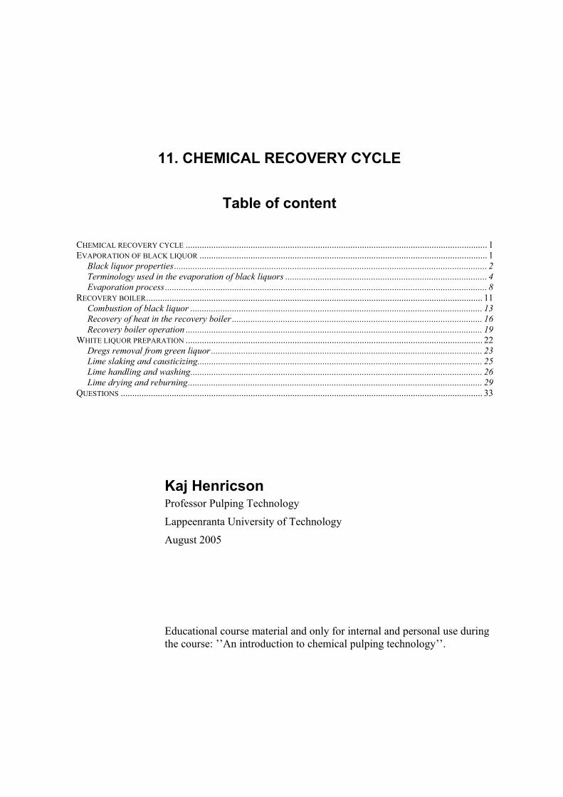
Chemical recovery cycle One of the main advantages of the kraft process is the efficient recovery of chemicals as compared to, for instance, sulfite pulp production. Picture 1 shows the principal unit operations of the kraft recovery process: evaporation of weak black liquor; combustion of thick black liquor in a recovery furnace to form a smelt, which is dissolved in water forming green liquor; causticizing sodium carbonate (Na2CO3) in green liquor to form white liquor containing sodium hydroxide (NaOH) and sodium sulfide (Na2S); and regeneration of lime mud in a limekiln.
Black liquor is recovered with a high recovery rate after cooking and the black liquor is combusted in the recovery boiler to produce heat and power in amounts that exceed their consumption at the kraft pulp mill. There is no need for external heat or power in the production of kraft pulp. The only exception is the limekiln, where usually oil or natural gas is used. In the lime kiln, the use of fossil fuels can be replaced with for instance combustion gases produced by gasifying bark. The water evaporated in the evaporation plan can be reused in white liquor preparation and in the fiber line as purified condensates.
Picture 1. Recovery cycles of chemicals for a kraft mill
Evaporation of black liquor The amount of water that has to be evaporated during black liquor evaporation depends on the amount of water introduced into the chemical recovery system, especially into the cooking and brown stock handling systems. The water to be evaporated originates from:
water content of wood water formed during cooking steam condensed during direct steam heating for instance in cooking and oxygen bleaching water in white liquor water used in brown stock washing. The excess water is determined by the dilution factor. various other water sources such as sealing water to leaking seals etc.
BAT

2
The amount of water that normally has to be evaporated from the weak black liquor after cooking and brown stock washing in order to produce thick black liquor for combustion in the recovery boiler is in the range of 7-9 m3/ton of pulp.
Black liquor properties Black liquor is composed of the organic material dissolved from the wood in the digester and at the oxygen delignification plant and of the chemicals used in cooking and oxygen bleaching. In the case of re-circulation of bleach plant effluents from final bleaching, also the dissolved material from bleaching and used chemicals in bleaching will be found in black liquor. In addition, non-process elements circulating with the active cooking chemical have accumulated in the chemical recovery cycle.
Black liquor contains extractives originating from the wood raw material. Extractives are removed from black liquor in the form of soap. The volatile components are removed from the condensates by stripping. Soap separation is important in order to avoid scaling of heat transfer surfaces during evaporation and to avoid foaming. Black liquor has a strong tendency to foam at low dry solids concentrations and the soap content contributes to the foaming tendency. The dry solids content of black liquor from the cooking and washing plant can be increased by adding to it some intermediate liquor from the evaporation plant before entering the evaporation plant in order to avoid foaming.
The scaling of heat transfer surfaces occurs in particular at high dry solids concentrations. The scaling tendency of black liquor depends for instance on the content of calcium soap in the black liquor. The contents of inert components like sodium sulfate and sodium carbonate also affect the scaling behavior of black liquors.
Table 1 shows the composition of a hardwood kraft black liquor. Table 2 shows the elementary composition of a softwood kraft black liquor. The composition of black liquor always depends on the used raw material and process conditions at the mill.
Table 1. Composition of black liquor dry solids from the kraft pulping of birch
Organics, % by weight 78 Degraded lignin, including Na and S, % 37.5 Isosaccharinic acids, including Na, % 22.6 Aliphatic acids, including Na, % 14.4 Resins and fatty acids, including Na, % 0.5 Polysaccharides, % 3.0 Inorganics, % by weight 22 NaOH, % 2.4 NaHS, % 3.6 Na2CO3 and K2CO3, % 9.2 Na2SO4, % 4.8 Na2S2O3, Na2SO3 and Na2Sx, % 0.5 NaCl, % 0.5 Non-process elements (Si, Ca, Fe, Mn, Mg, etc), % 0.2
Fapet 6B: p.B13

3
Table 2. Typical composition of black liquor from Scandinavian wood
Softwood (pine) Hardwood (birch) Typical Range Typical Range
Carbon, % 35.0 32-37 32.5 31-35 Hydrogen, % 3.6 3.2-3.7 3.3 3.2-3.5 Nitrogen, % 0.1 0.06-0.12 0.2 0.14-0.2 Oxygen, % 33.9 33-36 35.5 33-37 Sodium, % 19.0 18-22 19.8 18-22 Potassium, % 2.2 1.5-2.5 2.0 1.5-2.5 Sulfur, % 5.5 4-7 6.0 4-7 Chlorine, % 0.5 0.1-0.8 0.5 0.1-0.8 Inert, % 0.2 0.1-0.3 0.2 0.1-0.3 Total, % 100.0 - 100.0 -
Heating value The heating value of black liquor expresses the amount of heat that is released when combusting a specified amount of black liquor dry solids. The types of organic compounds present in black liquor and inorganic material in black liquor influence the heating value of black liquor. For instance, the type of lignin and the ratio between lignin and carbohydrates affect the heating value of black liquor as shown in Table 3. The reactions of inorganic material during combustion influence the heating value, and for instance the reduction of sulfate to sulfide in the recovery boiler consumes energy. All black liquors have to be tested separately to know the heating value and combustion properties in a recovery boiler.
Table 3. Heating values of black liquor components
Component MJ/kg Btu/lb m Softwood lignin 26.9 11.57 Hardwood lignin 25.11 10.8 Carbohydrates 13.555 5.83 Resins, fatty acids 37.71 16.22 Sodium sulfide 12.9 5.55 Sodium thiosulfate 5.79 2.49
Boiling point rise and viscosity When dimensioning an evaporation plant, one needs to know the boiling point rise and the viscosity of the liquor to be evaporated at the dry solids contents and the process conditions, such as temperature, prevailing during evaporation.
The temperature where black liquor boils is higher than the boiling temperature of water at the same pressure. The temperature difference is called the boiling point rise. As the dry solids content of black liquor increases, the boiling point increases as shown in Picture 2 for some black liquors.
Fapet 6B: p.B15
Fapet 6B: p.B18

4
Picture 2. Black liquor boiling point rise vs. dry solids concentration
The viscosity of black liquor depends on the temperature and dry solids content. The viscosity increases at higher dry solids contents, and a temperature increase decreases the viscosity as shown in Picture 3 for one black liquor after evaporation to a high dry solids content. The viscosity behavior varies from one black liquor to another. The evaporation of black liquors to high dry solids concentrations above 75% to 80% usually requires that these black liquors are heat treated at higher temperatures to reduce the viscosity of these liquors.
Picture 3. Effects of temperature and dry solids on the viscosity of one high dry solids black liquor
Terminology used in the evaporation of black liquors The evaporation stage or effect is one evaporator, or possibly several parallel evaporators operating at the same steam pressure level. The effects are numbered in the direction of the steam flow with the first effect operating at the highest steam pressure. Multiple-stage evaporation means evaporation in a plant consisting of a number of evaporator effects connected
Fapet 6B: p.B21
Modified by KH; Fapet 6B: p.B23

5
in series. An evaporation plant normally consists of 5-7 stages in series. Picture 4 shows a typical configuration. The condensate streams are segregated into fractions A, B and C according to their content of methanol and COD.
BLACK LIQUORFROM COOK
CONCENTRATEDBLACK LIQUOR
FRESHSTEAM
CONDENSERS
BLACK LIQUORFROM COOK
CONCENTRATEDBLACK LIQUOR
FRESHSTEAM
CONDENSERS
Picture 4. Typical configuration of a black liquor evaporation plant
The evaporator body or the evaporator itself is a heat exchanger unit used in the evaporation stages. One stage or effect might have several bodies in parallel. Picture 5 shows some commonly used evaporator designs in the evaporation of black liquors.
A
B
CA
B
C
Picture 5. Evaporators; A: rising film, B: falling film, C: forced circulation (or crystallizer)
The rising film evaporators [also called long-tube-vertical (LTV) or Kestner evaporator] were widely used for the evaporation of black liquor in the pulp industry until the mid-1980s. In a rising film evaporator, the forming steam causes the liquor to rise in the evaporation tubes. In later installations, the falling film evaporator and forced circulation evaporator are more common. In the falling film evaporator, the liquor is fed to the bottom of the evaporator from where it is pumped to the top of the heating element by a circulating pump and flows downwards on the heating surface by gravity. In the forced circulation evaporator, the black liquor is pumped through the tube heat exchanger to a separate chamber where the vapor is
KAM: p.28
Modified by KH; Fapet 6B: p.B46, 47, 51

6
released. The power needed in black liquor evaporation and the dimensioning of the heat transfer surfaces is dependent on the viscosity of the black liquor.
The term concentrator refers to the first effect where the liquor is evaporated to its final concentration. Earlier, the final concentrators were clearly separated from the multiple effect evaporation train and had a different design. In a modern evaporation plant, this difference does not exist but the terminology is still in use. The concentrators have to be cleaned regularly to remove scaling on the heat transfer surfaces, and evaporation plants usually have at least two concentrators in parallel so that one concentrator can be cleaned without influencing the operation of the whole evaporation plant.
Live steam, primary steam, or fresh steam is the clean steam from the boilers at the mill. Live steam is mainly only used in the first effect in the evaporation plant. The steam must be at saturation temperature or only slightly superheated. Primary condensate is the clean condensate from the live steam. Secondary steam or vapor is the steam evaporated from the black liquor. Vapor from the first effect is used as a heating medium in the second effect. Vapor from the second effect is then used in the third effect etc. The surface condenser is a water-cooled heat exchanger that condenses the vapor from the last evaporation effect.
The vapor always contains some organic materials evaporated from the liquor or even liquor droplets entrained in the steam flow. Secondary condensate is condensate derived from the vapor. It contains various levels of organic contaminants. It is therefore not as clean as primary condensate. Foul condensate is the most contaminated secondary condensate and has to be purified by stripping. The amount of organic material carried over into the condensates in the form of droplets is reduced by installing droplet separators in the steam phase of the evaporators. The condensates can on the side of the condensing steam of the heat transfer surface be segregated into a foul and clean condensate fraction.
Picture 6. Falling film evaporator A with condensate segregation and droplet separator B at the top of
the evaporator
Vapor condensate, which has some degree of contamination mainly consisting of methanol, is one of four fractions determined by the degree of contamination indicated in Table 4. Often, fractions 2 and 3 are combined. Vapor condensate fraction 1 and some fraction 2 can be used in bleaching and brown stock washing. Fraction 3 is used in the causticizing plant. Fraction 4 is treated in the stripper and is comparable to fraction 2 after stripping.
Vapor out
Vapor in
Liquor in
VentFlow 1%MeO H 10%FoulcondensateFlow 10%MeO H 80%
CleancondensateFlow 89%MeO H 10%
Liquor out
MPS, Andritz
B
A
7
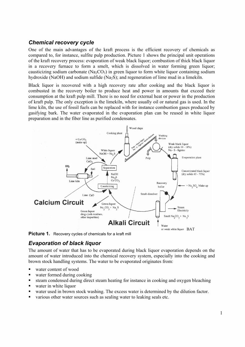
Table 4. Vapor condensate fractions from a modern 7-stage multiple falling film evaporation
Vapor condensate
fraction
Vapor condensate drawn
Flow, m3/adt
MeOH content,
mg/l
MeOH amount,
g/adt
Remarks
Fraction 1 From effects 2, 3 and 4
3.4 30 100 -
Fraction 2 From effects 5 and 6 2.5 300 700 - Fraction 3 From effect 7 and
surface condensate 2.0 600 1,200 Slightly odorous
Fraction 4 Foul condensate from evaporator
1.0 6,000 6,000 Malodorous
Total - 8.9 - 8,000 - Stripped condensate
From evaporation and cooking foul condensate stripping
1.6 300 500 Stripper MeOH purification efficiency=95%
The stripping column purifies the foul or contaminated condensate from the evaporation and cooking plants. Stripping is a mass transfer process where volatile gas components such as methanol and reduced organic sulfur compounds transfer from the liquid phase into the gas phase. Picture 7 shows a typical stripping column.
Picture 7. Stripping or distillation column
Non-condensable gases (NCG) are gaseous compounds that are liberated from the black liquor during evaporation and from condensates during stripping or come from the cooking plant. They are odorous, poisonous and inflammable. They require extraction from the evaporation plant and incineration in suitable process equipment such as a special burner or the limekiln.
Fapet 6B: p.B71
Fapet 6B: p.B54

8
Evaporation process The evaporation of black liquor has three principal unit operations: Separation of water from black liquor to generate concentrated black liquor and condensate, processing of condensate to segregate clean and fouled condensate fractions, and separation of soap from black liquor. The by far most common principle in the evaporation of kraft black liquor is the multistage evaporation concept illustrated in Picture 8.
The sum of the boiling point rise of black liquor in an evaporator plus the temperature gradient over the heat transfer surface in the evaporator is the temperature difference between the incoming steam and the vapor leaving the evaporator. The total temperature difference over all the effects in an evaporation plant is the sum of the temperature differences of the individual evaporators in the plant. There is a total temperature difference available for the evaporation plant and this difference influences the number of evaporator stages that can be used in series in a multistage evaporation plant.
Picture 8. Principle of multiple evaporation
Picture 9 shows a perspective of a multistage falling film evaporation plant. The steam or heat balance of the evaporation plant is dependent on the number of effects as shown in Table 5. The number of effects chosen is a balance between the investment costs of additional effects, the investment cost and amount of heat transfer surfaces in the individual effects and the savings in steam due to additional effects.
Picture 9. Multistage falling film evaporation plant
Fapet 6B: p.B9
Modified by KH; Fapet 6B: p.B41

9
Table 5. Steam economy and specific heat consumption in multiple evaporation including an integrated stripper column
Number of stages
Steam economy, ton H2O/ton steam
Specific heat consumption, MJ/ton H2O
4 3.7-3.6 630-650 5 4.3-4.1 550-570 6 5.1-4.9 460-480 7 6.2-5.9 390-400
The mixed liquor sequence in the five-stage evaporation plant shown in Picture 10 is a favorable sequence commonly used in the evaporation of black liquors. The mixed liquor flow pattern gives the following advantages:
Soap separation from the intermediate liquor is optimum due to the concentration of 27%-30% dry solids and the low temperature of approximately 60°C.
Liquor feed to effects 3 and 4 in parallel allows balancing the feed according to the feed liquor temperature and operating temperature in the effects.
Release of non-condensable gases that enter with the feed liquor is evened between the effects. The gases vent from effects 4 and 5.
Picture 10. Mixed flow sequence
The main factors affecting soap separation from black liquor are soap solubility and the soap skimming tank configuration. The solubility of soap depends on the concentration of dry solids in black liquor and black liquor temperature as shown in Picture 11.
Picture 11. Effect of temperature and solids content on soap solubility
Soap separation is often done in two stages; from the weak liquor tank from where the black liquor is fed to the evaporation plant and from the intermediate tank after initial evaporation in two or three evaporation effects. In a skimmer tank, a retention time of 6h-7h is used. A double
Fapet 6B: p.B44
Fapet 6B: p.B84
Fapet 6B: p.B42

10
liquor tank arrangement is commonly used where weak liquor enters tank I and flows by gravity to tank II. Soap skimming is carried out batch-wise as indicated in Picture 12.
Picture 12. Soap skimming
Black liquor is also evaporated by flashing, especially in connection with continuous digesters, where the hot extraction black liquor at the digester is allowed to flash and the flash steam is used to steam and preheat the chips. The flashing of black liquor and condensates takes place to some extent inside the evaporation plant as the black liquor or condensates flow to an effect at a lower pressure level. During flashing, the dry solids content of the black liquor increases with an amount depending on the amount of steam separated from the black liquor during flashing. Special multi-flash evaporator systems have been developed for the evaporation of black liquor but the number of industrial installations is small.
Vapor compression evaporation VCE is sometimes used for the pre-evaporation of black liquors that have a dry solids concentration of less than 25% and that have a moderate boiling point rise. Picture 13 shows the principle of vapor compression evaporation. In the system, the compressor increases the pressure and the temperature of the released vapor so that it can be reused inside the same unit. The normal power consumption of a vapor compression pre-evaporator is 11-14 kWh/ton of H2O. The feasibility of vapor compression evaporation depends on the price of available power.
Fapet 6B: p.B86

11
Picture 13. Principle of vapor compression evaporator (VCE)
Recovery boiler The recovery boiler is a chemical reactor for the recovery of the cooking chemicals used and for the generation of heat from dissolved inorganic and organic material in the black liquor. The recovery of cooking chemicals in a recovery boiler includes several steps:
combustion of the organic material in black liquor to generate heat production of sodium fume to capture sulfur-containing combustion residues reduction of the inorganic sulfur compounds to Na2S production of a smelt of molten Na2CO3 and Na2S recovery of inorganic dust from the flue gas recovery of the heat formed during combustion
Picture 14 is a schematic diagram of a two-drum recovery boiler and Picture 15 shows some of the chemical reactions taking place inside the recovery boiler. The components of the recovery boilers in Picture 14 are: furnace, where the combustion of black liquor takes place, superheaters for heating the steam with hot combustion gases, boiler generating bank where water boils, and economizers that recover residual heat in the flue gases and cool the flue gases. In the steam drum, water and steam are segregated. The air enters through primary and secondary air ports and tertiary air ports. The black liquor enters through liquor guns in the lower part of the furnace. The smelt exits through smelt spouts to the dissolving tank. The heat transfer surfaces are cleaned by soot blowing steam. The flue gas is cleaned in an electrostatic precipitator.
Fapet 6B: p.B42

12
Picture 14. Schematic diagram of a two-drum recovery boiler
The recovery boiler consists of heat transfer surfaces made of steel tubing. The tubes contain steam or water, and the heat generated inside the recovery boiler is recovered into the water and steam inside the tubes as in normal power boilers. Recovery boilers have a lower power-to-heat ratio compared to normal power boilers mainly due to limitations coming from the sodium and sulfur content in the black liquor.
Recovery boilers produce steam with lower heat and pressure than normal power boilers. Some of the limiting issues concerning recovery boilers are: corrosion and cracking risks, fouling of heat transfer surfaces, air emission requirements, today almost zero SO2 is possible, very low NOx emissions, no or low odor from the boiler, safety, and smelt-water explosion risk.
KRB: p.5

13
Picture 15. Some conceptual chemical reactions in a recovery boiler
In spite of all limitations, the recovery boiler is an efficient and working solution for the combustion of black liquors and for the recovery of heat. The sizes of recovery boilers have increased as pulp mills have become bigger, and the capacity of recovery boilers matches the capacity on the fiber line. The steam values are developing towards higher steam pressures and higher steam temperatures, which will give a higher power-to-steam ratio.
Combustion of black liquor Black liquor is sprayed at high dry solids content into the recovery boiler as small droplets. During the first stage, the water in the droplets evaporates and the droplet dries. Black liquor drying occurs near the liquor gun at the wall. The droplet velocity is high, about 10 m/s, when the droplet enters the furnace.
The second stage is the devolatilization of pyrolysis gases and the release of volatiles. At the same time, the droplets swell and a flame appears. As black liquor volatiles start to release, the speed of the droplet decreases due to the swelling of the black liquor droplet. Small droplets are carried upwards by the hot gas.
During the third stage, char burning starts and the droplet size decreases. Char and smelted sodium fall into the bed where the reduction of sulfur continues under reducing conditions. Picture 16 shows the different stages of black liquor combustion in the black liquor droplets and the char bed in the lower part of the furnace.
BAT

14
CHAR BEDPrimary Air
1st Secondary Air
2nd Secondary Air
3rd Secondary Air
Liquor Guns
smelt
char intochar bed
smalldroplets
drying
devolatilization
char combustion in flight
pyrolysis gases
Picture 16. Stages in the combustion of black liquor
Table 6 presents some typical times for the different stages of the combustion of black liquor droplets. Picture 17 shows the swelling behavior of the droplets during combustion.
Table 6. Stages in black liquor combustion
Stage Characterized by Time scale in furnace for a 2mm droplet
Drying Water evaporation Constant diameter after initial swelling
0.1-0.2s
Devolatilization Appearance of flame, ignition Swelling of the droplet Release of volatiles
0.2-0.3s
Char burning Disappearance of flame Decreasing diameter Reduction reactions
0.5-1s
Smelt Constant or increasing diameter Reoxidation
long
Picture 17. Characteristic swelling behavior of black liquor during combustion
Fapet 6B: p.B109
Fapet 6B: p.B109
KRB, MPS

15
During char combustion, reduction reactions occur. Carbon has a major role in the reduction reactions. Na2SO4 reacts with carbon to form Na2S. When the carbon in the char bed burns, it causes the reduction of sodium.
Na2S+2O2 -> Na2SO4
Na2SO4+2C -> Na2S+2CO2
Na2SO4+4C -> Na2S+2CO
Degree of reduction (%) = ( ) 100422
2 ×+ SONaSNa
SNa
The degree of reduction of sulfur in the white liquor is determined by the operation of the recovery boiler. The Na2SO4 is an inert circulating compound in the liquor system, and this reduces process efficiency. A normal degree of reduction in recovery boilers is slightly above 90%.
Picture 18 shows the bottom of a recovery boiler with black liquor entering the boiler through the liquor guns shown in Picture 19. Air is added above the bottom and the char bed in such a way that reducing conditions are maintained near the char bed. The smelt flows from the recovery boiler into the smelt dissolver.
Picture 18. Recovery boiler lower furnace with
hot char bed
Picture 19. Arrangement of a black liquor gun,
port opening and liquor spray
The recovery boiler has a risk of smelt and water explosion due to the presence of the porous hot char bed containing molten sodium salts. The water and smelt can come into direct contact due to a recovery boiler tube failure causing a smelt and water explosion in a recovery boiler. An emergency rapid drain system minimizes potential damage. Water remains at the lowest part of the furnace to provide cooling for the floor tubes. If all water drains from the floor tubes, the heat from the hot char bed will damage the boiler tubes.
Fapet 6B: p.B113
KRB: p.8

16
The risk of a recovery boiler tube failure is decreased and the use of corrosion resistant materials in the recovery boiler has increased the lifetime of a boiler. The materials vary in different parts of the boiler according to the conditions prevailing in the different parts of the boiler. For instance, the lower portion of the recovery boiler is often made of composite tube material as shown in Picture 20. The outer surface of the boiler tube is covered by corrosion-resistant stainless steel. Also, keeping the amounts of certain corrosive chemicals, like chlorine and potassium, below critical levels in the chemical recovery cycle reduces corrosion.
Picture 20. Lower furnace arrangement with composite tube wall construction
Recovery of heat in the recovery boiler Picture 21 shows the material flows in a steam boiler such as a recovery boiler. A recovery boiler is a steam boiler that has the following components or systems:
Black liquor handling and feeding equipment for feeding the thick black liquor into the boiler. The black liquor is fed at a dry solids concentration above 65%, in some boilers built after 1990 the dry solids content is even over 80%. At high dry solids concentrations, the black liquor becomes highly viscous and is difficult to handle unless kept at an elevated temperature.
Air fans, air ducts and air pre-heater. The combustion air is pre-heated in the recovery boiler house and with air pre-heaters before being fed into the recovery boiler furnace.
Flue gas cleaning. The heat is recovered from the flue gas in the economizer and the flue gases are cleaned with an electric precipitator to recover dust-containing sodium and sulfur.
Smelt outlet ducts. Combustion chamber or furnace where the combustion of black liquor occurs. Tubing for steam and water that forms the heat exchangers that cool the hot combustion gases. Feed water system. Control systems.
The recovery boiler produces superheated steam through the combustion of black liquor with air, and the steam is taken to a turbine to produce power as shown in Picture 21. A higher temperature and pressure of the superheated steam going to the turbine generates more power from the heat generated in the boiler.
From the turbine, the steam for the pulp production process is taken out at two pressure levels: extraction or high pressure steam with a pressure of about 12 bars that is used for instance to heat the digester and back pressure or low pressure steam that is used for instance at the evaporation plant and the pulp dryer. Primary condensate from the condensing of fresh live steam can be returned to the feed water tank feeding the boiler with clean water as shown in Picture 22. Feed water is usually preheated with steam. Exhaust steam from the turbine is taken to a surface condenser.
KRB: p.12

17
Picture 21. Material flows in a steam boiler
Picture 22. Flow diagram of a cogeneration
steam cycle The black liquor is combusted in the furnace of the recovery boiler. About 70%-75% of the heat value of the black liquor will convert into superheated steam when the dry solids content of the black liquor is 72%-85%. The smelt consumes heat due to the heat of the smelt and the chemical reactions to form the reduced sulfur in the smelt. About 15% of the heat will go to the smelt. The rest of the heat is lost with the flue gases. Picture 23 shows how the combustion heat is divided between recovered heat, heat to smelt and heat losses in the flue gases as the flue gas temperature and the dry solids content of the black liquor vary.
Picture 23. Black liquor dry solids heat to smelt, as loss in flue gases, and recovered into steam
Picture 24 shows the principle of the water system in a recovery boiler and Picture 25 a perspective of the recovery boiler construction. Feed water is pumped into the boiler and enters the first heat transfer surface or economizer (11). The water flows from the economizer to the steam drum (6). In the steam drum, steam separates from water. Separation occurs by gravity,
Fapet 6B: p.B206 Fapet 6B: p.B207
Fapet 6B: p.B316

18
screens and cyclone separators in order to minimize the amount of water droplets in the steam. Downcomers (7) feed saturated water to the evaporative surfaces that are the walls of the combustion chamber in the boiler and tubes in the boiler bank. Saturated steam (12) exits from the drum and flows through the superheaters (13) and is heated to superheated steam. The role of superheaters is to heat the steam well above saturation before feeding the steam to the turbine.
11
12
1310
6
7
11
12
1310
6
7
1111
1212
13131010
66
77
Picture 24. Principle of a water tube boiler
The hot flue gases carrying the heat from combustion meet the heat surfaces in the following order: superheater – boiler bank – economizer. The hottest gas heats the steam in the superheater and the coldest gas heats the feed water interring the boiler. The boiling water cools the walls of the boiler.
The feed water system of the recovery boiler consists of the feed water tank (1), deaerator, boiler feed water pump (2), control valve, and feed water piping (3). The water from the economizer generates clean attemperating water (5) from steam in a sweet water condenser (4). The attemperating water is used to control the temperature of the steam in the superheaters and thus to control the surface temperature of the tubes in the superheaters. Picture 26 shows some typical superheater platens. The main steam valves control steam flow (9). The steam from superheaters flows through the main steam line (10) to the turbine.
Picture 25. Water circulation system
Modified by KH; Fapet 6B: p.B205
Fapet 6B: p.B122
19
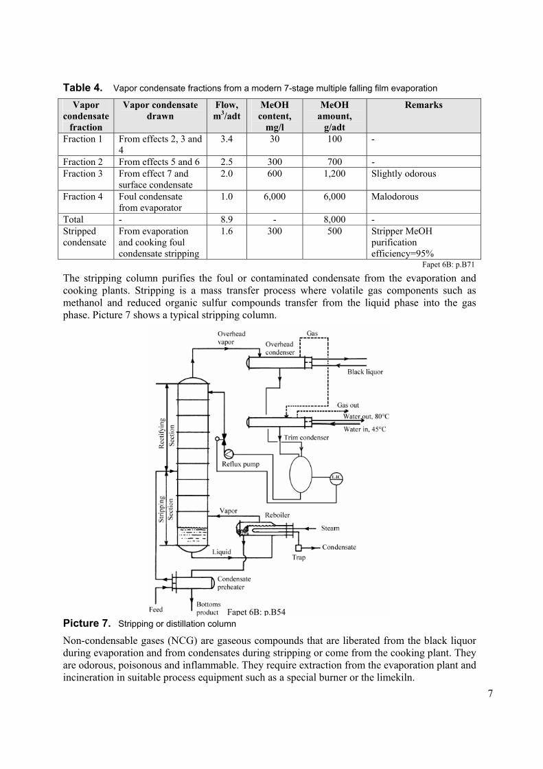
Picture 26. Arrangement of two superheater
platens
Picture 27. Air system for a recovery boiler
The air is typically delivered at several horizontal elevations to ensure complete combustion and to minimize emissions. In boilers built after the year 2000, air is often introduced over almost the whole height of the furnace section of the recovery boiler. Picture 27 shows a boiler air system. It has an inlet duct with silencer (1), venturi for airflow measurement (2), air blower (3), air heater (4), distribution ducts (5), and air ducts (6 and 7). Pressure and temperature measuring devices are also necessary at proper locations. Air intake is typically high inside the boiler house to ensure an even vertical temperature profile and to recover heat losses through boiler walls and openings.
Recovery boiler operation Spent kraft pulping liquors contain inorganic salts. During the combustion reactions, the temperatures increase to levels where significant amounts of inorganic chemicals vaporize. Small char fragments and black liquor particles also entrain into the flue gas flow. Combustion and chemical reactions take place in the hot gas phase and cause deposits that collect on heat transfer surfaces and foul them.
The deposits formed on the heat transfer surfaces consist mainly of Na2CO3, Na2SO4, Na2S and small amounts of NaCl and potassium salts. The composition of the deposits varies according to the mechanics of deposit formation, type of black liquor and combustion conditions. Deposits in the lower part of the furnace generally contain more Na2CO3 and Na2S and less Na2SO4, NaCl and potassium salts that deposits in the upper furnace. Picture 28 shows typical compositions of deposits in a recovery boiler.
KRB: p.13 Fapet 6B: p.B121

20
Picture 28. Composition of fireside deposits
The fouling of individual heat transfer surfaces is removed and controlled by soot blowing. Soot blowing is done with steam and is directed to the critical heat transfer surfaces. Soot blowers are usually in pairs on the left and right side of the boiler as shown in Picture 29. Picture 30 shows a soot blower cleaning a tube bank.
Picture 29. Recovery boiler
Picture 30. Sketch of a soot blower cleaning a
tube bank
Potassium and chloride in the black liquor influence the fouling of heat transfer surfaces and the corrosion of recovery boilers. Even small amounts of potassium and chloride influence the sticky temperature of dust. The sticky temperature is the temperature above which dust contains sufficient amounts of sodium in molten state to stick to the heat transfer surfaces and form deposits as shown in Picture 31. The deposits of chemicals on the heat transfer surfaces become an effective barrier to heat transfer from the flue gas to the tube wall. From the wall, the heat is transferred to the steam or water inside the tube.
KRB: p.15
KRB: p.296
Fapet 6B: p.B9

21
Tgas
Tsteam
Tube wall
Deposit
Steam(water)
Flue gas
T0 T70
Q.
Picture 31. Deposit on superheater
0
20
40
60
80
100
500 600 700 800 900 1000
Temperature [°C]Pe
rcen
t mel
t [w
t-%]
Tflow
Tsticky
Picture 32. Different compositions give different
melting behavior
The chloride and potassium levels influence the melting behavior of dust in recovery boilers and decrease the melting point of dust as shown in Picture 32. The graphs in the picture show the melting behavior of some typical recovery boiler dusts with varying potassium and chlorine content. Chloride levels at Scandinavian and North American mills are typically 0.2%-0.8% of mass. Potassium levels at Scandinavian and North American mills can vary widely: 1%-4% of mass. Chloride and potassium enter the chemical recovery cycle mainly with the wood and enrich into the recovery cycle. The level of chloride and potassium must be kept sufficiently low. The levels are controlled by purging dust from the recovery boiler as dust tends to enrich more in chlorine and potassium compared to the rest of the recovery cycle.
Increasing chloride and potassium contents reduces the melting point of sodium-containing dust. Only a few percentages on molten metals make the metals sticky. Tsticky is the temperature when enough sodium is in molten state and makes a dust particle stick to surfaces of the recovery boiler. Tsticky is usually in recovery boiler defined to the temperature when 15% of the metals are in molten state. Tflow is the temperature when enough sodium is in molten state to make the metal a flowing smelt. Metals start to flow when over 70% is in molten form but usually in connection with recovery boilers Tflow is defined as the temperature when 85% of the metals are in molten state.
Picture 33 shows the material balance of a recovery boiler and how the generated steam is used inside the boiler and as steam being fed to the turbine at the mill. Dust from the heating surfaces is mixed with the black liquor and fed back into the boiler. Some of the dust may be purged from the recovery cycle to control the content of non-process elements, in particular chloride and potassium.
KRB, MPS
KRB, MPS

22
Picture 33. Material balance based on 100kg of black liquor solids
White liquor preparation Several separate processes are needed when converting the green liquor into white liquor: dregs removal from green liquor, slaking of lime, causticizing reaction, white liquor separation from lime mud with lime mud washing, and drying and reburning or calcining of lime. Picture 34 shows the white liquor preparation system and the separate processes in the system.
Picture 34. A diagram of white liquor preparation and lime reburning
KRB: p.19
Fapet 6B: p.B162
23
Dregs removal from green liquor Green liquor results when the smelt from the recovery boiler is dissolved in weak white liquor or water in the dissolving tank. Green liquor is an aqueous solution mainly consisting of sodium sulfides, sulfates and carbonates. It contains some unburned char and some non-process elements that have a low solubility in the green liquor and that can be removed by sedimentation or filtration.
Most impurities in the lime cycle come from green liquor. Solid particles in green liquor mix with the lime and accumulate in the lime cycle. Many of these impurities can be removed as dregs from the green liquor. Without dregs separation, the need for lime makeup may be 30% of the lime circulation. With good purification of green liquor, the lime makeup required can decrease to 3%-5%. The separation of the solids, called dregs, from green liquor normally uses sedimentation or filtration methods. Green liquor purification concepts in industrial use include:
Clarification Sedimentation Sludge blanket clarification
Filtration Cake filtration with or without precoat Cross flow filtration
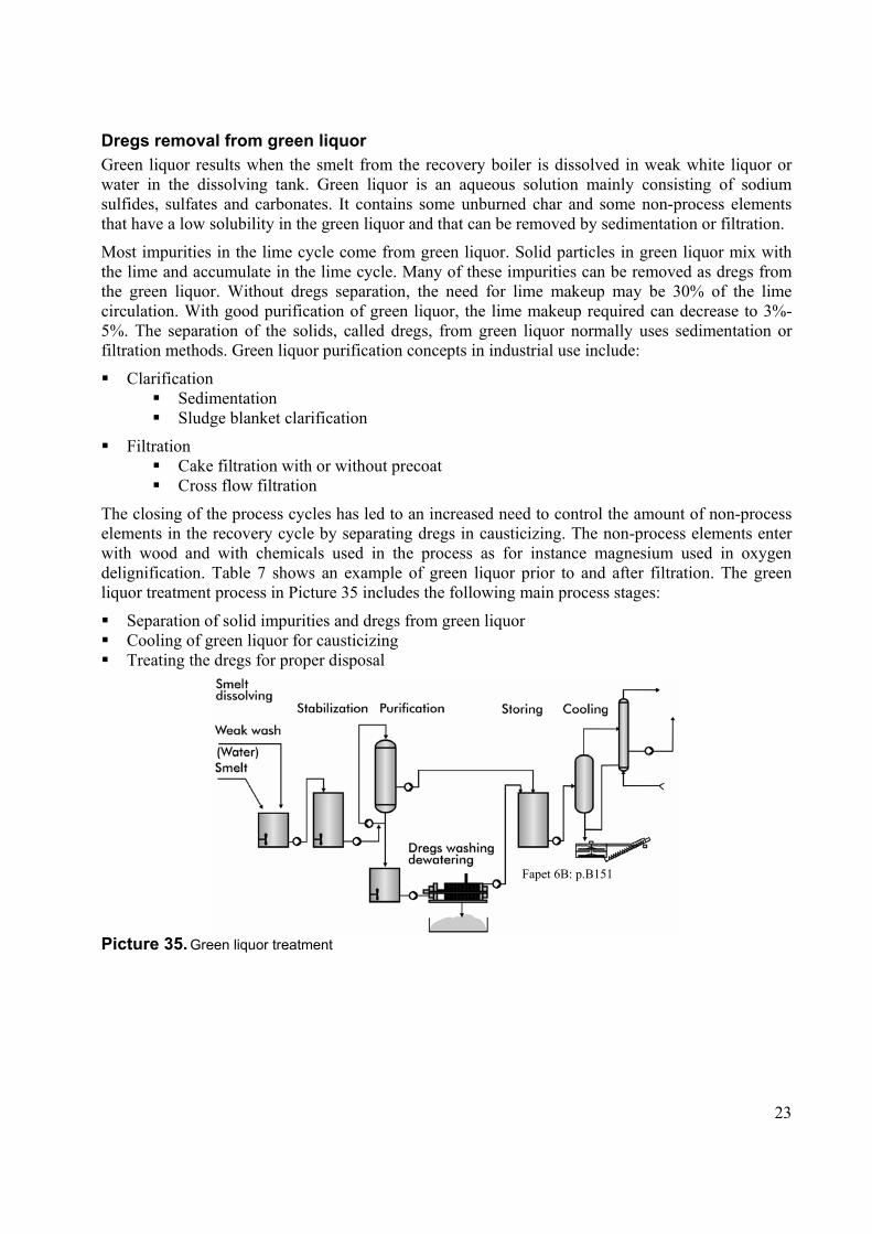
The closing of the process cycles has led to an increased need to control the amount of non-process elements in the recovery cycle by separating dregs in causticizing. The non-process elements enter with wood and with chemicals used in the process as for instance magnesium used in oxygen delignification. Table 7 shows an example of green liquor prior to and after filtration. The green liquor treatment process in Picture 35 includes the following main process stages:
Separation of solid impurities and dregs from green liquor Cooling of green liquor for causticizing Treating the dregs for proper disposal
Picture 35. Green liquor treatment
Fapet 6B: p.B151

24
Table 7. Removal of various elements from green liquor
Raw green liquor Filtered liquor Dregs, mg/l 310 7 Potassium (K), mg/l 5.3 5.3 Magnesium (Mg), mg/l 53 1.1 Aluminum (Al), mg/l 60 40 Iron (Fe), mg/l 17 8.2 Manganese (Mn), mg/l 16 2.2 Copper (Cu), mg/l 1.3 0.88 Phosphorus (P), mg/l 43.8 41.2
Green liquor can be clarified by sedimentation. In sedimentation, the density difference between the solid material and the liquid in green liquor separates the solid material by allowing it to settle. A clarifier is normally an open cylindrical tank as Picture 36 shows. The solid material that is heavier than the liquid settles to the bottom of the clarifier to form sludge. The clear liquor in the upper part of the clarifier is removed as an overflow.
Picture 36. A clarifier
In green liquor cross flow filters a thin film of green liquor fall onto a vertical filter cloth. Some falling liquor is forced through the vertical filter cloth while most of the liquor including the dregs continues to fall to the bottom in the film. The liquor is recirculated to the top of the filter to maintain the film by pumping. Filtration continues and the sludge thickens in the circulation until reaching the desired sludge density. Thickened sludge is discarded from the filter by the pressure inside the filter.
Fapet 6B: p.B146
MPS

25
Picture 37. Cross-flow filter for green liquor
filtration
Picture 38. Green liquor cooler
It is necessary to cool the green liquor and to control the temperature of the green liquor that enters the slaker in recausticizing to prevent the liquor from boiling in the slaker. Boiling may occur due to the heat generated as a result of the exothermic slaking reaction. Cooling of green liquor, and even of weak liquor, is difficult with indirect heat exchangers because of the rapid scaling and plugging due to reduced solubility at lower temperatures.
Lime slaking and causticizing Green liquor is mixed with calcium oxide, CaO, and the calcium oxide slakes with water and forms calcium hydroxide, Ca(OH)2. The calcium hydroxide reacts with the Na2CO3 in the green liquor to produce NaOH and CaCO3. Picture 39 shows a slaker in which lime is slaked into green liquor.
Picture 39. Slaker
The slaking of lime is a strongly exothermic reaction:
CaO + H2O - Ca(OH)2 + 65 kJ/mol
The slaking reaction takes about 10-30 minutes to complete depending on the quality of lime. The heat released due to the slaking reaction must be distributed evenly to the liquor by agitation to avoid local overheating. The temperature of the solution has a major influence on the reaction rate. Below 70°C, the reaction rate is significantly slower than at the normal operating temperatures close to 100°C.
MPS
MPS
MPS
26
The causticizing reaction is an equilibrium reaction:
Ca(OH)2 (s) + Na2CO3 (aq) - 2 NaOH (aq) + CaCO3 (s) The reaction does not have any significant heat effect. Calcium hydroxide and CaCO3 are insoluble and participate in the reaction as solids. The causticizing reaction begins and continues to about 70% completion during the slaking which takes 10-20 minutes.
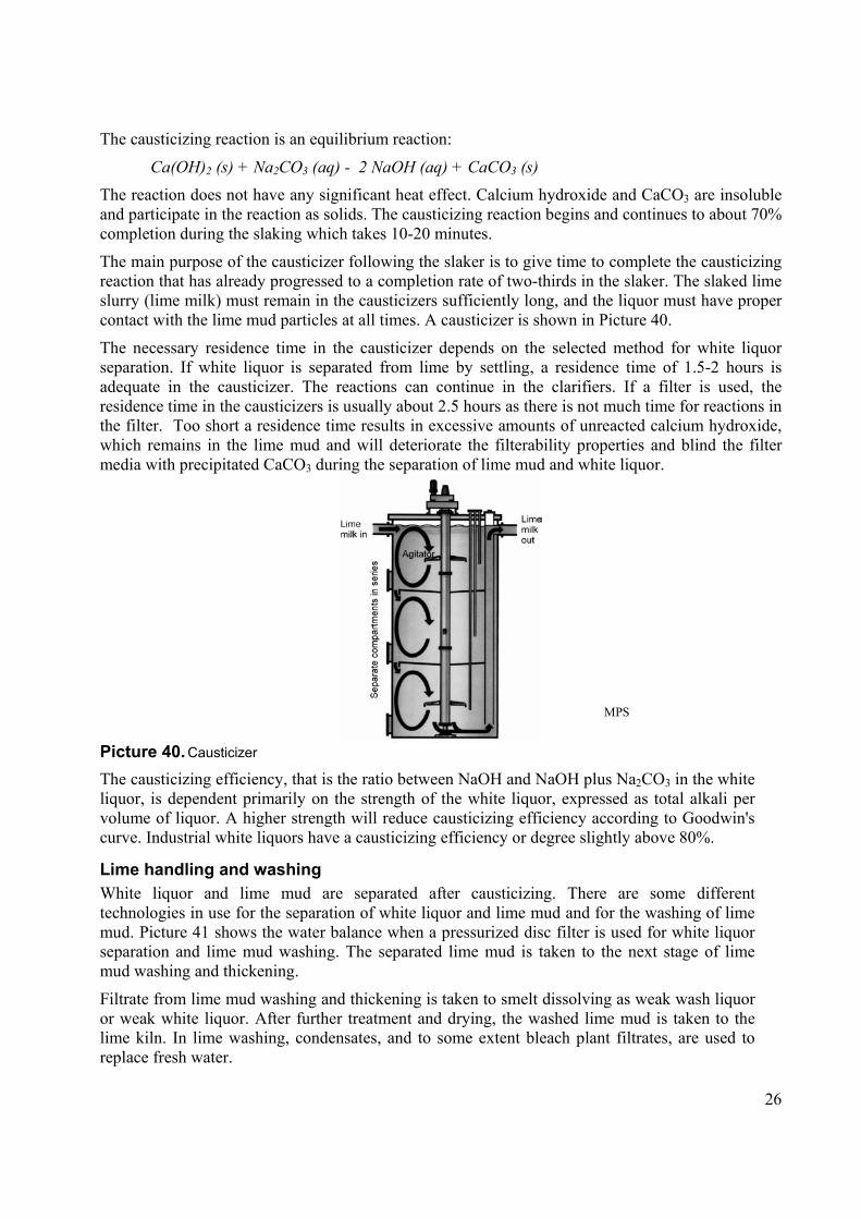
The main purpose of the causticizer following the slaker is to give time to complete the causticizing reaction that has already progressed to a completion rate of two-thirds in the slaker. The slaked lime slurry (lime milk) must remain in the causticizers sufficiently long, and the liquor must have proper contact with the lime mud particles at all times. A causticizer is shown in Picture 40.
The necessary residence time in the causticizer depends on the selected method for white liquor separation. If white liquor is separated from lime by settling, a residence time of 1.5-2 hours is adequate in the causticizer. The reactions can continue in the clarifiers. If a filter is used, the residence time in the causticizers is usually about 2.5 hours as there is not much time for reactions in the filter. Too short a residence time results in excessive amounts of unreacted calcium hydroxide, which remains in the lime mud and will deteriorate the filterability properties and blind the filter media with precipitated CaCO3 during the separation of lime mud and white liquor.
Picture 40. Causticizer
The causticizing efficiency, that is the ratio between NaOH and NaOH plus Na2CO3 in the white liquor, is dependent primarily on the strength of the white liquor, expressed as total alkali per volume of liquor. A higher strength will reduce causticizing efficiency according to Goodwin's curve. Industrial white liquors have a causticizing efficiency or degree slightly above 80%.
Lime handling and washing White liquor and lime mud are separated after causticizing. There are some different technologies in use for the separation of white liquor and lime mud and for the washing of lime mud. Picture 41 shows the water balance when a pressurized disc filter is used for white liquor separation and lime mud washing. The separated lime mud is taken to the next stage of lime mud washing and thickening.
Filtrate from lime mud washing and thickening is taken to smelt dissolving as weak wash liquor or weak white liquor. After further treatment and drying, the washed lime mud is taken to the lime kiln. In lime washing, condensates, and to some extent bleach plant filtrates, are used to replace fresh water.
MPS

27
Picture 41. Water balance for causticizing with a pressurized disc filter for white liquor separation
Other commonly used machines for white liquor and lime mud separation and mud washing are the candle filter shown in Picture 42 and the disc filter shown in Picture 43. The heat and water balances when using these machines are somewhat different than the ones when using pressurized disk filters.
Picture 42. A candle filter
Picture 43. Pressurized disc filtration for white
liquor separation and lime mud washing
Fapet 6B: p.B169
MPS
MPS, Andritz

28
The white liquor produced and separated from the lime mud is taken to the digester for cooking. Table 8 shows typical properties of white liquor.
Table 8. An example of white liquor composition
Compound Concentration, g NaOH/l
Concentration, g Na2O/l
As compound, g/l
NaOH 95 73.6 95 Na2S 40 31.8 39 Na2CO3 23 17.8 30.5 Na2SO4 4 3.1 7.1 Na2S2O3 2 1.6 4.0 Na2SO3 0.5 0.4 0.8 Other compounds - - 3.0 Effective alkali 135 105.4 - Active alkali 115 89.5 - Total alkali 164.5 128.3 179.4 Sulfidity, % 29.6 S/Na equivalent ratio 0.58 Causticizing degree, % 80.5 Reduction degree, % based on total S
82.2
Reduction degree, % based on total SO4
90.9
The target in lime mud dewatering is to complete lime mud washing and increase the dry solids so that the lime mud can be dried thermally and fed to the lime kiln. The moisture in the lime mud has a considerable effect on the energy consumption of the lime kiln. Dry solids contents of 80%-90% are possible after mechanical dewatering. The water soluble alkali content in the lime mud after mechanical filter dewatering is under 0.1% as Na2O on dry mud. A low content of sodium is necessary for the trouble-free operation of the lime kiln.
Picture 44. Lime mud washing and dewatering
Fapet 6B: p.B171
MPS

29
Lime drying and reburning The lime reburning process is shown in Picture 45 and consists of the following unit operations:
Pumping of lime mud, that is CaCO3, from lime mud storage Mechanical dewatering of lime mud to a high dry solids content Thermal dewatering in the kiln or in a separate cyclone Heating and calcining Cooling of the lime, that is calcium oxide, product Screening and crushing of lime Conveying of lime to storage
Picture 45. Lime reburning process
The physical size of a rotary lime kiln, with a capacity of 500 to 550 tons of reburned lime/day, is 4m-4.5m in diameter and 100m-140m in length. The production of a kiln of this size matches a white liquor production of about 7,000 m3/day, corresponding to a pulp production of slightly above 2,000 t/day. The kiln is supported by three or four piers.
Picture 46. Limekiln
A pneumatic dryer for lime mud is an emerging drying method where the lime is dried with the exhaust gases from the limekiln in a separate cyclone. Lime mud is fed to a flue gas stream, where the heat of the flue gases dries the mud. A cyclone separates dry mud and feeds it to the kiln as shown in Picture 47.
Fapet 6B: p.B10
Fapet 6B: p.B179

30
Picture 47. A pneumatic dryer for lime mud
The traditional method for the drying of mud is the chain section of the rotary kiln. Picture 48 shows a chain system. The length of the chain section of the limekiln is chosen so that the mud is completely dry when leaving the chain section. The length of the chain section is usually about 20% of the total kiln length.
Picture 48. Chain system
Lime reburning Heating or reburning of lime mud converts lime mud to lime according to the following reaction:
CaCO3 - CaO + CO2
Dissociation of CaCO3 to CaO and CO2 starts when the temperature is above 820°C. Increasing the temperature accelerates the reaction. Reburning is done at a temperature of about 1,100°C in order to obtain sufficiently fast reaction rates.
Lime mud entering the limekiln also contains some unreacted lime CaO, water, a small amount of alkali, other impurities and non-process elements. The amount of impurities in the lime mud is typically about 7%-10% and depends on the amount of impurities introduced into the lime cycle with the green liquor and the makeup lime. Non-process elements normally present in the lime cycle are magnesium (Mg), aluminum (Al), silica (Si), phosphorus (P), iron (Fe), manganese (Mn) and sulfur (S). Silica is a major problem when pulping annual plants or tropical wood. Sulfur comes for instance from the burning of non-condensable gases in the lime kiln. Table 9 provides an example of different lime compositions in the case of a Scandinavian mill and a mill for mixed tropical hardwood. The major difference between the mill limes is in the content of silica.
Fapet 6B: p.B181
MPS, Andritz

31
Table 9. An example of different lime compositions
Component (expressed as
oxides)
Makeup lime
Scandinavian mill with softwood or hardwood
as raw material
Mill with mixed tropical hardwood
as raw material CaO, wt. % 93 N/A N/A Na2O, wt. % 0.06 N/A N/A SiO2, wt. % 2.5 0.4 7.9 MgO, wt. % 1.3 1.3 1.2 Fe2O3, wt. % 0.5 0.06 0.4 MnO, wt. % 0.04 0.1 0.01
Silica is a serious impurity in the lime cycle and causes problems especially when pulping annual plants and tropical wood. The lime mud becomes difficult to handle and dewater with an increasing silica content as shown in Picture 49.
Picture 49. Lime mud dry substance and silica in lime mud
The cell structure of annual plants contains solid silica particles that dissolve in the cooking liquor, proceed with the black liquor into the smelt, and end up in the green liquor in dissolved form. Silica precipitates with lime mud during recausticizing because of the low solubility of calcium silicate in white liquor. Lime mud from the pulping of annual plants cannot often be reburned at all. A large portion of the lime mud from the pulping of tropical hardwood must be dumped to keep the recausticizing plant in operation.
Depending on the design of the burner in the lime kilns, also fuels other than fuel oil and natural gas can be used. A combination burner can have ports for non-condensable gases and arrangements for feeding methanol. Primary air passes through the burner, cools it, and stabilizes the flame.
Fapet 6B: p.B148
Fapet 6B: p.B147

32
Picture 50. Burner
Picture 51. Temperature profile in the limekiln
Lime kilns have a refractory lining that protects the kiln shell from overheating and reduces the heat loss to an acceptable level. The temperature distribution of lime kilns is wide from the cold feed-end housing to the hot firing hood. In conventional kilns, where the mud is dried inside the kiln, the lowest temperature is about 100°C. In the flame zone, the temperature is about 1,250°C. In large kilns with a shell diameter of over 4.5m, the flame zone lining has to tolerate even higher temperatures like 1,300°C-1,350°C. In modern kilns with a separate mud dryer, the cold-end temperature is 400°C-600°C. Picture 52 shows the lime kiln brick lining zones. Each zone has a lining of a certain material and thickness.
Picture 52. Lime kiln brick lining zones
Fapet 6B: p.B180
Fapet 6B: p.B163
Fapet 6B: p.B184

33
Questions 1. The source of water, organic material and inorganic material in black liquor. / Mustalipeän
sisältämän veden, orgaanisen aineen ja epäorgaanisen aineen alkuperä. 2. Properties of black liquor influencing the evaporation plant. / Mustalipeän ominaisuudet
haihduttamon kannalta. 3. Multistage evaporation plant, number of stages and steam consumption, soap separation. /
Monivaihehaihduttamo, vaiheiden lukumäärä ja höyrynkulutus, suovan erotus. 4. The most common evaporator designs used in black liquor evaporation. / Yleisimmät
haihdutinkonstruktiot mustalipeän haihdutuksessa. 5. Condensate handling and reuse at kraft pulp mills. / Lauhteiden käsittely ja uudelleenkäyttö
sulfaattisellutehtailla. 6. List the main steps of the kraft recovery process. / Luettele sulfaattiprosessin
talteenottopuolen tärkeimmät vaiheet. 7. The smelt reactions in a recovery boiler. / Sulareaktiot soodakattilassa. 8. The combustion of black liquor in a recovery boiler; the black liquor droplet during
combustion, and the different stages of combustion. / Mustalipeän poltto soodakattilassa; mustalipeäpisaran käyttäytyminen polton aikana ja palamisen eri vaiheet.
9. Recovery of heat in a recovery boiler. / Soodakattilan energian talteenottojärjestelmä. 10. Scaling of heat transfer surfaces in the recovery boiler. / Soodakattilan lämmönsiirtopintojen
likaantuminen. 11. The main factors influencing the heating value of black liquors. / Polttoarvoon vaikuttavat
tärkeimmät tekijät. 12. Influence of chlorine and potassium on recovery boiler operation; what can be done to
control chlorine and potassium levels? / Kloorin ja kaliumin vaikutus soodakattilan toimintaan; mitä voidaan tehdä kloori- ja kaliumtasojen hallitsemiseksi.
13. Green liquor treatment, measures to reduce the need for makeup lime. / Viherlipeän käsittely, miten vähennetään korvauskalkin tarvetta.
14. Slaking of lime and causticizing reactions. / Kalkin sammutus ja kaustisointireaktiot. 15. The operation principle and construction of the lime kiln. / Meesauunin toimintaperiaate ja
rakenne.
Related Documents