11-11 00 01 10-1 DEPARTMENT OF VETERANS AFFAIRS VHA MASTER SPECIFICATIONS WM. S MIDDLETON MEMORIAL VA HOSPITAL UPGRADE BUILDING AUTOMATION SYSTEM : Project No. 607-12-119 TABLE OF CONTENTS Section 00 01 10 DIVISION 00 - SPECIAL SECTIONS DATE 00 01 15 List of Drawing Sheets 09-11 DIVISION 01 - GENERAL REQUIREMENTS 01 00 00 General Requirements 06-11 01 32 16.15 Project Schedules (Small Projects – Design/Bid/Build 04-10 01 33 23 Shop Drawings, Product Data, and Samples 11-08 01 42 19 Reference Standards 09-11 01 74 19 Construction Waste Management 09-10 DIVISION 02 – EXISTING CONDITIONS 02 41 00 Demolition 06-10 DIVISION 03 – CONCRETE NOT USED DIVISION 04 – MASONRY NOT USED DIVISION 05 – METALS NOT USED DIVISION 06 – WOOD,PLASTICS AND COMPOSITES NOT USED DIVISION 07 - THERMAL AND MOISTURE PROTECTION 07 84 00 Firestopping 10-11 07 92 00 Joint Sealants 02-11 DIVISION 08 - OPENINGS NOT USED DIVISION 09 – FINISHES 09 91 00 Painting 04-09 DIVISION 10 – SPECIALTIES NOT USED DIVISION 11 – EQUIPMENT NOT USED

Welcome message from author
This document is posted to help you gain knowledge. Please leave a comment to let me know what you think about it! Share it to your friends and learn new things together.
Transcript
11-11
00 01 10-1
DEPARTMENT OF VETERANS AFFAIRS
VHA MASTER SPECIFICATIONS
WM. S MIDDLETON MEMORIAL VA HOSPITAL UPGRADE BUILDING AUTOMATION SYSTEM : Project No. 607-12-119
TABLE OF CONTENTS Section 00 01 10
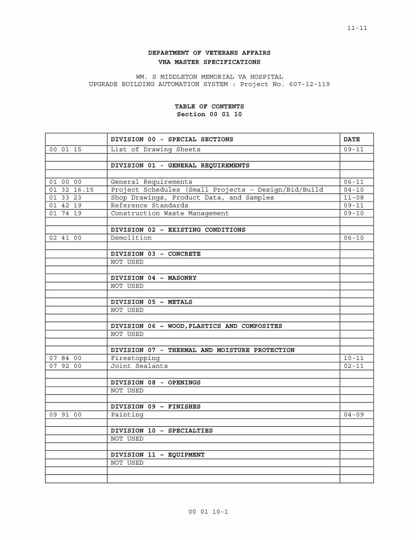
DIVISION 00 - SPECIAL SECTIONS DATE
00 01 15 List of Drawing Sheets 09-11 DIVISION 01 - GENERAL REQUIREMENTS 01 00 00 General Requirements 06-11 01 32 16.15 Project Schedules (Small Projects – Design/Bid/Build 04-10 01 33 23 Shop Drawings, Product Data, and Samples 11-08 01 42 19 Reference Standards 09-11 01 74 19 Construction Waste Management 09-10 DIVISION 02 – EXISTING CONDITIONS 02 41 00 Demolition 06-10 DIVISION 03 – CONCRETE NOT USED DIVISION 04 – MASONRY NOT USED DIVISION 05 – METALS NOT USED DIVISION 06 – WOOD,PLASTICS AND COMPOSITES NOT USED DIVISION 07 - THERMAL AND MOISTURE PROTECTION 07 84 00 Firestopping 10-11 07 92 00 Joint Sealants 02-11 DIVISION 08 - OPENINGS NOT USED DIVISION 09 – FINISHES 09 91 00 Painting 04-09 DIVISION 10 – SPECIALTIES NOT USED DIVISION 11 – EQUIPMENT NOT USED
11-11
00 01 10-2
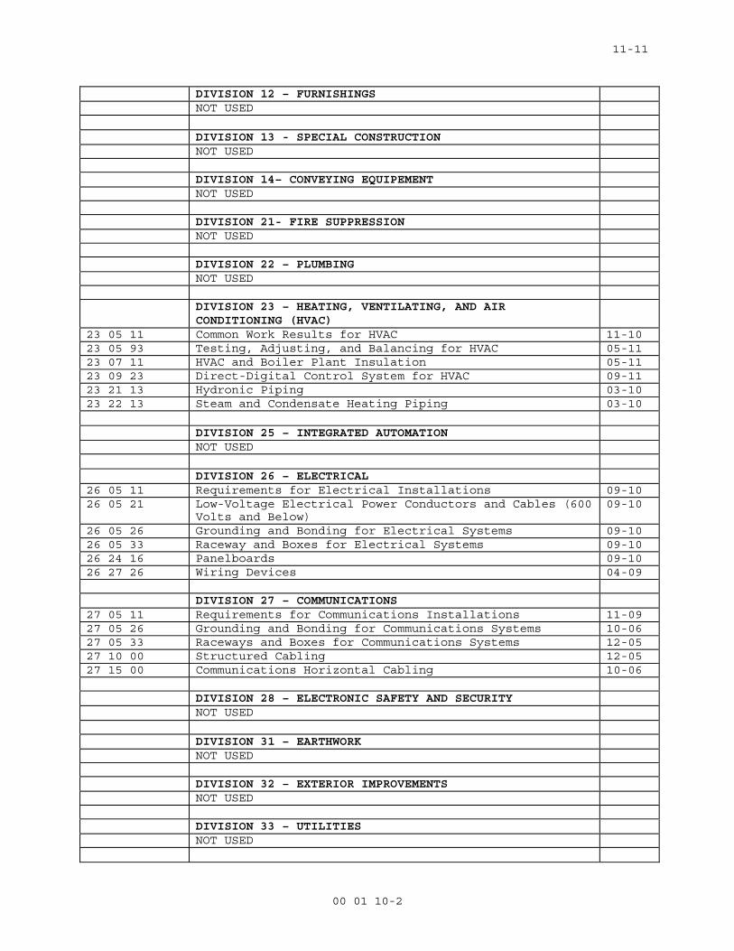
DIVISION 12 – FURNISHINGS NOT USED DIVISION 13 - SPECIAL CONSTRUCTION NOT USED DIVISION 14– CONVEYING EQUIPEMENT NOT USED DIVISION 21- FIRE SUPPRESSION NOT USED DIVISION 22 – PLUMBING NOT USED DIVISION 23 – HEATING, VENTILATING, AND AIR
CONDITIONING (HVAC)
23 05 11 Common Work Results for HVAC 11-10 23 05 93 Testing, Adjusting, and Balancing for HVAC 05-11 23 07 11 HVAC and Boiler Plant Insulation 05-11 23 09 23 Direct-Digital Control System for HVAC 09-11 23 21 13 Hydronic Piping 03-10 23 22 13 Steam and Condensate Heating Piping 03-10 DIVISION 25 – INTEGRATED AUTOMATION NOT USED DIVISION 26 – ELECTRICAL 26 05 11 Requirements for Electrical Installations 09-10 26 05 21 Low-Voltage Electrical Power Conductors and Cables (600
Volts and Below) 09-10
26 05 26 Grounding and Bonding for Electrical Systems 09-10 26 05 33 Raceway and Boxes for Electrical Systems 09-10 26 24 16 Panelboards 09-10 26 27 26 Wiring Devices 04-09 DIVISION 27 – COMMUNICATIONS 27 05 11 Requirements for Communications Installations 11-09 27 05 26 Grounding and Bonding for Communications Systems 10-06 27 05 33 Raceways and Boxes for Communications Systems 12-05 27 10 00 Structured Cabling 12-05 27 15 00 Communications Horizontal Cabling 10-06 DIVISION 28 – ELECTRONIC SAFETY AND SECURITY NOT USED DIVISION 31 – EARTHWORK NOT USED DIVISION 32 – EXTERIOR IMPROVEMENTS NOT USED DIVISION 33 – UTILITIES NOT USED
11-11
00 01 10-3
DIVISION 34 – TRANSPORTATION NOT USED
09-11
00 01 15 - 1
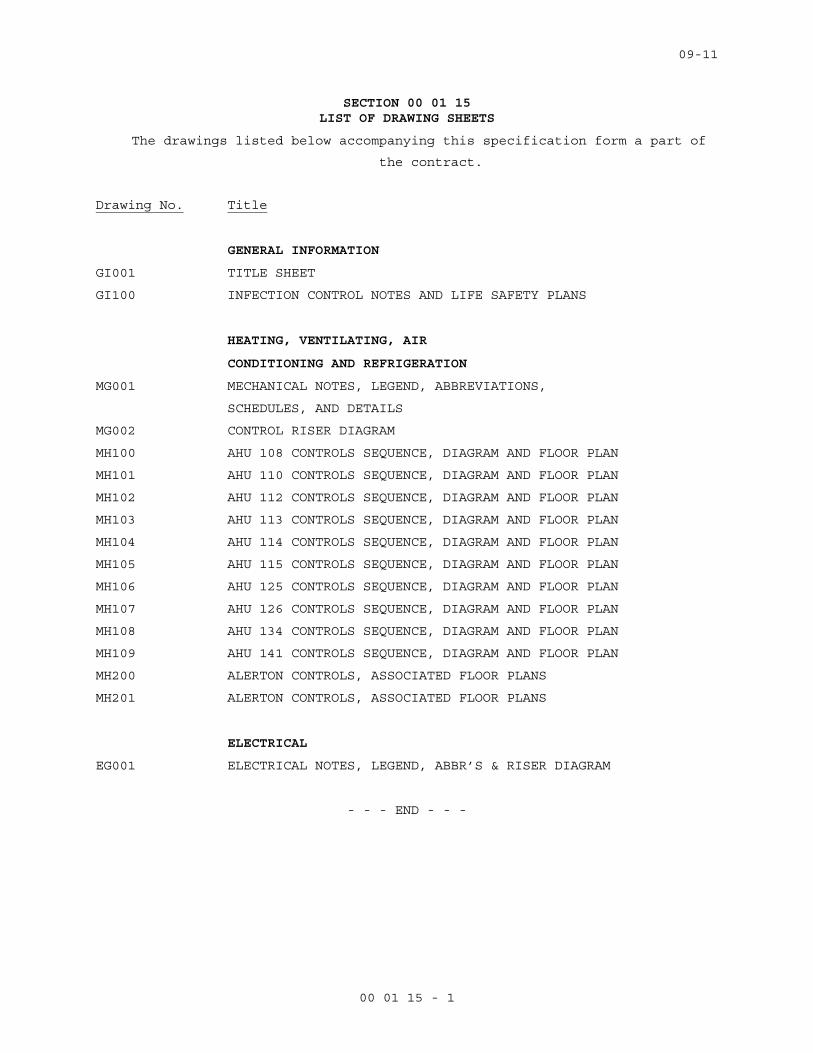
SECTION 00 01 15 LIST OF DRAWING SHEETS
The drawings listed below accompanying this specification form a part of
the contract.
Drawing No. Title
GENERAL INFORMATION
GI001 TITLE SHEET
GI100 INFECTION CONTROL NOTES AND LIFE SAFETY PLANS
HEATING, VENTILATING, AIR
CONDITIONING AND REFRIGERATION
MG001 MECHANICAL NOTES, LEGEND, ABBREVIATIONS,
SCHEDULES, AND DETAILS
MG002 CONTROL RISER DIAGRAM
MH100 AHU 108 CONTROLS SEQUENCE, DIAGRAM AND FLOOR PLAN
MH101 AHU 110 CONTROLS SEQUENCE, DIAGRAM AND FLOOR PLAN
MH102 AHU 112 CONTROLS SEQUENCE, DIAGRAM AND FLOOR PLAN
MH103 AHU 113 CONTROLS SEQUENCE, DIAGRAM AND FLOOR PLAN
MH104 AHU 114 CONTROLS SEQUENCE, DIAGRAM AND FLOOR PLAN
MH105 AHU 115 CONTROLS SEQUENCE, DIAGRAM AND FLOOR PLAN
MH106 AHU 125 CONTROLS SEQUENCE, DIAGRAM AND FLOOR PLAN
MH107 AHU 126 CONTROLS SEQUENCE, DIAGRAM AND FLOOR PLAN
MH108 AHU 134 CONTROLS SEQUENCE, DIAGRAM AND FLOOR PLAN
MH109 AHU 141 CONTROLS SEQUENCE, DIAGRAM AND FLOOR PLAN
MH200 ALERTON CONTROLS, ASSOCIATED FLOOR PLANS
MH201 ALERTON CONTROLS, ASSOCIATED FLOOR PLANS
ELECTRICAL
EG001 ELECTRICAL NOTES, LEGEND, ABBR’S & RISER DIAGRAM
- - - END - - -
06-11
01 00 00 -1
SECTION 01 00 00 GENERAL REQUIREMENTS
1.1 GENERAL INTENTION
A. Contractor shall completely prepare site for building operations,
including demolition and removal of existing structures, and furnish
labor and materials and perform work for upgrading the HVAC Building
Automation System (BAS) as required by drawings and specifications.
B. Visits to the site by Bidders may be made only by appointment with the
Medical Center Engineering Officer.
C. Offices of Integrated Design Group, as Architect-Engineers, will render
certain technical services during construction. Such services shall be
considered as advisory to the Government and shall not be construed as
expressing or implying a contractual act of the Government without
affirmations by Contracting Officer or his duly authorized
representative.
D. All employees of general contractor and subcontractors shall comply with
VA security management program and obtain permission of the VA police,
be identified by project and employer, and restricted from unauthorized
access.
E. Prior to commencing work, general contractor shall provide proof that a
OSHA certified “competent person” (CP) (29 CFR 1926.20(b)(2) will
maintain a presence at the work site whenever the general or
subcontractors are present.
F. Training:
1. All employees of general contractor or subcontractors shall have the
10-hour OSHA certified Construction Safety course and /or other
relevant competency training, as determined by VA CP with input from
the ICRA team. The General Contractor’s “Competent Person” shall have
the 30-hour OSHA certified Construction Safety course and /or other
relevant competency training, as determined by VA CP with input from
the ICRA team.
2. Submit training records of all such employees for approval before the
start of work.
06-11
01 00 00 -2
1.2 STATEMENT OF BID ITEM(S)
A. ITEM I, GENERAL CONSTRUCTION: Work includes general construction,
alterations, mechanical and electrical work, necessary removal of
existing construction and certain other items.
1.3 SPECIFICATIONS AND DRAWINGS FOR CONTRACTOR
A. AFTER AWARD OF CONTRACT, 0 sets of specifications and drawings will be
furnished.
B. Additional sets of drawings may be made by the Contractor, at
Contractor's expense, from reproducible sepia prints furnished by
Issuing Office. Such sepia prints shall be returned to the Issuing
Office immediately after printing is completed.
1.4 CONSTRUCTION SECURITY REQUIREMENTS
A. Security Plan:
1. The security plan defines both physical and administrative security
procedures that will remain effective for the entire duration of the
project.
2. The General Contractor is responsible for assuring that all sub-
contractors working on the project and their employees also comply
with these regulations.
B. Security Procedures:
1. General Contractor’s employees shall not enter the project site
without appropriate badge. They may also be subject to inspection of
their personal effects when entering or leaving the project site.
2. For working outside the “regular hours” as defined in the contract,
The General Contractor shall give 3 days notice to the Contracting
Officer so that security arrangements can be provided for the
employees. This notice is separate from any notices required for
utility shutdown described later in this section.
3. No photography of VA premises is allowed without written permission
of the Contracting Officer.

06-11
01 00 00 -3
4. VA reserves the right to close down or shut down the project site and
order General Contractor’s employees off the premises in the event of
a national emergency. The General Contractor may return to the site
only with the written approval of the Contracting Officer.
C. Guards: (RESERVED)
D. Key Control:
1. The General Contractor shall provide a Trilogy mechanical punch lock
on all temporary construction barriers with an override key core
compatible to the Medical Center’s locking system (Sargent 6-Pin
removable core). The VA will provide the contractor with the
removable override core for this lockset. Provide the lock
combination(s) to the VA Project Manager for the purpose of security
inspections of every area of the project including tool boxes and
parked machines and take any emergency action.
E. Document Control:
1. Before starting any work, the General Contractor/Sub Contractors
shall submit an electronic security memorandum describing the
approach to following goals and maintaining confidentiality of
“sensitive information”.
2. The General Contractor is responsible for safekeeping of all
drawings, project manual and other project information. This
information shall be shared only with those with a specific need to
accomplish the project.
4. Certain documents, sketches, videos or photographs and drawings may
be marked “Law Enforcement Sensitive” or “Sensitive Unclassified”.
Secure such information in separate containers and limit the access
to only those who will need it for the project. Return the
information to the Contracting Officer upon request.
5. These security documents shall not be removed or transmitted from the
project site without the written approval of Contracting Officer.
6. All paper waste or electronic media such as CD’s and diskettes shall
be shredded and destroyed in a manner acceptable to the VA.
7. Notify Contracting Officer and Site Security Officer immediately when
there is a loss or compromise of “sensitive information”.
06-11
01 00 00 -4
8. All electronic information shall be stored in specified location
following VA standards and procedures using an Engineering Document
Management Software (EDMS).
a. Security, access and maintenance of all project drawings, both
scanned and electronic shall be performed and tracked through the
EDMS system.
b. “Sensitive information” including drawings and other documents may
be attached to e-mail provided all VA encryption procedures are
followed.
F. Motor Vehicle Restrictions
1. Vehicle authorization request shall be required for any vehicle
entering the site and such request shall be submitted 24 hours before
the date and time of access. Access shall be restricted to picking up
and dropping off materials and supplies.
2. Separate permits shall be issued for General Contractor and its
employees for parking in designated areas only.
1.5 FIRE SAFETY
A. Applicable Publications: Publications listed below form part of this
Article to extent referenced. Publications are referenced in text by
basic designations only.
1. American Society for Testing and Materials (ASTM):
E84-2009.............Surface Burning Characteristics of Building
Materials
2. National Fire Protection Association (NFPA):
10-2010..............Standard for Portable Fire Extinguishers
30-2008..............Flammable and Combustible Liquids Code
51B-2009.............Standard for Fire Prevention During Welding,
Cutting and Other Hot Work
70-2011..............National Electrical Code
241-2009.............Standard for Safeguarding Construction,
Alteration, and Demolition Operations

06-11
01 00 00 -5
3. Occupational Safety and Health Administration (OSHA):
29 CFR 1926..........Safety and Health Regulations for Construction
B. Fire Safety Plan: Establish and maintain a fire protection program in accordance with 29 CFR 1926. Prior to start of work, prepare a plan
detailing project-specific fire safety measures, including periodic
status reports, and submit to COTR and Facility Safety Officer for
review for compliance with contract requirements in accordance with
Section 01 33 23, SHOP DRAWINGS, PRODUCT DATA AND SAMPLES Prior to any
worker for the contractor or subcontractors beginning work, they shall
undergo a safety briefing provided by the general contractor’s competent
person per OSHA requirements. This briefing shall include information on
the construction limits, VAMC safety guidelines, means of egress, break
areas, work hours, locations of restrooms, use of VAMC equipment, etc.
Documentation shall be provided to the COTR that individuals have
undergone contractor’s safety briefing.
C. Site and Building Access: Maintain free and unobstructed access to
facility emergency services and for fire, police and other emergency
response forces in accordance with NFPA 241.
D. Separate temporary facilities, such as trailers, storage sheds, and
dumpsters, from existing buildings and new construction by distances in
accordance with NFPA 241. For small facilities with less than 6 m (20
feet) exposing overall length, separate by 3m (10 feet).
E. Temporary Construction Partitions:
1. Install and maintain temporary construction partitions to provide
smoke-tight separations between construction areas and adjoining
areas. Construct partitions of gypsum board or treated plywood (flame
spread rating of 25 or less in accordance with ASTM E84) on both
sides of fire retardant treated wood or metal steel studs. Extend the
partitions through suspended ceilings to floor slab deck or roof.
Seal joints and penetrations. At door openings, install Class C, ¾
hour fire/smoke rated doors with self-closing devices.
2. Install fire-rated temporary construction partitions as shown on
drawings to maintain integrity of existing exit stair enclosures,
exit passageways, fire-rated enclosures of hazardous areas,
horizontal exits, smoke barriers, vertical shafts and openings
enclosures.

06-11
01 00 00 -6
3. Close openings in smoke barriers and fire-rated construction to
maintain fire ratings. Seal penetrations with listed through-
penetration firestop materials in accordance with Section 07 84 00,
FIRESTOPPING.
F. Temporary Heating and Electrical: Install, use and maintain
installations in accordance with 29 CFR 1926, NFPA 241 and NFPA 70.
G. Means of Egress: Do not block exiting for occupied buildings, including
paths from exits to roads. Minimize disruptions and coordinate with COTR
and facility Safety Officer.
H. Egress Routes for Construction Workers: Maintain free and unobstructed
egress. Inspect daily. Report findings and corrective actions weekly to
COTR and facility Safety Officer.
I. Fire Extinguishers: Provide and maintain extinguishers in construction
areas and temporary storage areas in accordance with 29 CFR 1926, NFPA
241 and NFPA 10.
J. Flammable and Combustible Liquids: Store, dispense and use liquids in
accordance with 29 CFR 1926, NFPA 241 and NFPA 30.
K. Standpipes: (RESERVED)
L. Sprinklers: (RESERVED)
M. Existing Fire Protection: Do not impair automatic sprinklers, smoke and
heat detection, and fire alarm systems, except for portions immediately
under construction, and temporarily for connections. Provide fire watch
for impairments more than 4 hours in a 24-hour period. Request
interruptions in accordance with Article, OPERATIONS AND STORAGE AREAS,
and coordinate with COTR and facility Safety Officer. All existing or
temporary fire protection systems (fire alarms, sprinklers) located in
construction areas shall be tested as coordinated with the medical
center. Parameters for the testing and results of any tests performed
shall be recorded by the medical center and copies provided to the COTR.
N. Smoke Detectors: Prevent accidental operation. Remove temporary covers
at end of work operations each day. Coordinate with COTR and facility
Safety Officer.
06-11
01 00 00 -7
O. Hot Work: Perform and safeguard hot work operations in accordance with
NFPA 241 and NFPA 51B. Obtain permits from VA Project Manager. Designate
contractor's responsible project-site fire prevention program manager to
permit hot work.
P. Fire Hazard Prevention and Safety Inspections: Inspect entire
construction areas weekly. Coordinate with, and report findings and
corrective actions weekly to COTR and facility Safety Officer.
Q. Smoking: The William S. Middleton VA Hospital and campus is a smoke-free
environment. Smoking is prohibited in all spaces, except two designated
smoking shelters. Smoking is prohibited in and adjacent to construction
areas inside existing buildings and additions under construction.
Violators will be issued a citation. R. Dispose of waste and debris in
accordance with NFPA 241. Remove from buildings daily.
S. Perform other construction, alteration and demolition operations in
accordance with 29 CFR 1926.
1.6 OPERATIONS AND STORAGE AREAS
A. The Contractor shall confine all operations (including storage of
materials) on Government premises to areas authorized or approved by the
Contracting Officer. The Contractor shall hold and save the Government,
its officers and agents, free and harmless from liability of any nature
occasioned by the Contractor's performance.
B. Temporary buildings (e.g., storage sheds, shops, offices) and utilities
may be erected by the Contractor only with the approval of the
Contracting Officer and shall be built with labor and materials
furnished by the Contractor without expense to the Government. The
temporary buildings and utilities shall remain the property of the
Contractor and shall be removed by the Contractor at its expense upon
completion of the work. With the written consent of the Contracting
Officer, the buildings and utilities may be abandoned and need not be
removed.
C. The Contractor shall, under regulations prescribed by the Contracting
Officer, use only established roadways, or use temporary roadways
constructed by the Contractor when and as authorized by the Contracting
Officer. When materials are transported in prosecuting the work,
vehicles shall not be loaded beyond the loading capacity recommended by
06-11
01 00 00 -8
the manufacturer of the vehicle or prescribed by any Federal, State, or
local law or regulation. When it is necessary to cross curbs or
sidewalks, the Contractor shall protect them from damage. The Contractor
shall repair or pay for the repair of any damaged curbs, sidewalks, or
roads.
D. Working space and space available for storing materials shall be limited
to space within the contractor’s job trailer and within the jobsite’s
space being renovated.
E. Workmen are subject to rules of Medical Center applicable to their
conduct.
F. Execute work so as to interfere as little as possible with normal
functioning of Medical Center as a whole, including operations of
utility services, fire protection systems and any existing equipment,
and with work being done by others. Use of equipment and tools that
transmit vibrations and noises through the building structure, are not
permitted in buildings that are occupied, during construction, jointly
by patients or medical personnel, and Contractor's personnel, except as
permitted by COTR where required by limited working space.
1. Do not store materials and equipment in other than assigned areas.
2. Schedule delivery of materials and equipment to immediate
construction working areas within buildings in use by Department of
Veterans Affairs in quantities sufficient for not more than two work
days. Provide unobstructed access to Medical Center areas required to
remain in operation.
3. Where access by Medical Center personnel to vacated portions of
buildings is not required, storage of Contractor's materials and
equipment will be permitted subject to fire and safety requirements.
F. Utilities Services: Where necessary to cut existing pipes, electrical
wires, conduits, cables, etc., of utility services, or of fire
protection systems or communications systems (except telephone), they
shall be cut and capped at suitable places where shown; or, in absence
of such indication, where directed by COTR. All such actions shall be
coordinated with the Utility Company involved:
G. Phasing: To insure such executions, Contractor shall furnish the COTR
with a schedule of approximate phasing dates on which the Contractor
06-11
01 00 00 -9
intends to accomplish work in each specific area of site, building or
portion thereof. In addition, Contractor shall notify the COTR two weeks
in advance of the proposed date of starting work in each specific area
of site, building or portion thereof. Arrange such phasing dates to
insure accomplishment of this work in successive phases mutually
agreeable to Medical Center Director, COTR and Contractor.
H. Buildings will be occupied during performance of work; but immediate
areas of alterations will be vacated.
1. Contractor shall take all measures and provide all material necessary
for protecting existing equipment and property in affected areas of
construction against dust and debris, so that equipment and affected
areas to be used in the Medical Centers operations will not be
hindered. Contractor shall permit access to Department of Veterans
Affairs personnel and patients through other construction areas which
serve as routes of access to such affected areas and equipment.
Coordinate alteration work in areas occupied by Department of
Veterans Affairs so that Medical Center operations will continue
during the construction period.
I. Construction Fence: (RESERVED)
J. When a building is turned over to Contractor, Contractor shall accept
entire responsibility therefore.
1. Contractor shall maintain a minimum temperature of 4 degrees C (40
degrees F) at all times, except as otherwise specified.
2. Contractor shall maintain in operating condition existing fire
protection and alarm equipment. In connection with fire alarm
equipment, Contractor shall make arrangements for pre-inspection of
site with Fire Department or Company (Department of Veterans Affairs
or municipal) whichever will be required to respond to an alarm from
Contractor's employee or watchman.
K. Utilities Services: Maintain existing utility services for Medical
Center at all times. Provide temporary facilities, labor, materials,
equipment, connections, and utilities to assure uninterrupted services.
Where necessary to cut existing water, steam, gases, sewer or air pipes,
or conduits, wires, cables, etc. of utility services or of fire
protection systems and communications systems (including telephone),
06-11
01 00 00 -10
they shall be cut and capped at suitable places where shown; or, in
absence of such indication, where directed by COTR.
1. No utility service such as water, gas, steam, sewers or electricity,
or fire protection systems and communications systems may be
interrupted without prior approval of COTR. Electrical work shall be
accomplished with all affected circuits or equipment de-energized.
When an electrical outage cannot be accomplished, work on any
energized circuits or equipment shall not commence without the
Medical Center Director’s prior knowledge and written approval. Refer
to specification Sections 26 05 11, REQUIREMENTS FOR ELECTRICAL
INSTALLATIONS, 27 05 11 REQUIREMENTS FOR COMMUNICATIONS INSTALLATIONS
for additional requirements.
2. Contractor shall submit a request to interrupt any such services to
COTR, in writing, 48 hours in advance of proposed interruption.
Request shall state reason, date, exact time of, and approximate
duration of such interruption.
3. Contractor will be advised (in writing) of approval of request, or of
which other date and/or time such interruption will cause least
inconvenience to operations of Medical Center. Interruption time
approved by Medical Center may occur at other than Contractor's
normal working hours.
4. Major interruptions of any system must be requested, in writing, at
least 15 calendar days prior to the desired time and shall be
performed as directed by the COTR.
5. In case of a contract construction emergency, service will be
interrupted on approval of COTR. Such approval will be confirmed in
writing as soon as practical.
6. Whenever it is required that a connection fee be paid to a public
utility provider for new permanent service to the construction
project, for such items as water, sewer, electricity, gas or steam,
payment of such fee shall be the responsibility of the Government and
not the Contractor.
L. Abandoned Lines: All service lines such as wires, cables, conduits,
ducts, pipes and the like, and their hangers or supports, which are to
be abandoned but are not required to be entirely removed, shall be
sealed, capped or plugged. The lines shall not be capped in finished

06-11
01 00 00 -11
areas, but shall be removed and sealed, capped or plugged in ceilings,
within furred spaces, in unfinished areas, or within walls or
partitions; so that they are completely behind the finished surfaces.
M. To minimize interference of construction activities with flow of Medical
Center traffic, comply with the following:
1. Keep roads, walks and entrances to grounds, to parking and to
occupied areas of buildings clear of construction materials, debris
and standing construction equipment and vehicles.
N. Coordinate the work for this contract with other construction operations
as directed by COTR. This includes the scheduling of traffic and the use
of roadways, as specified in Article, USE OF ROADWAYS.
1.7 ALTERATIONS
A. Survey: Before any work is started, the Contractor shall make a thorough
survey with the COTR areas of buildings in which alterations occur and
areas which are anticipated routes of access, and furnish a report,
signed by both, to the Contracting Officer. This report shall list by
rooms and spaces:
1. Existing condition and types of resilient flooring, doors, windows,
walls and other surfaces not required to be altered throughout
affected areas of building.
2. Existence and conditions of items such as plumbing fixtures and
accessories, electrical fixtures, equipment, venetian blinds, shades,
etc., required by drawings to be either reused or relocated, or both.
3. Shall note any discrepancies between drawings and existing conditions
at site.
4. Shall designate areas for working space, materials storage and routes
of access to areas within buildings where alterations occur and which
have been agreed upon by Contractor and COTR.
B. Any items required by drawings to be either reused or relocated or both,
found during this survey to be nonexistent, or in opinion of COTR to be
in such condition that their use is impossible or impractical, shall be
furnished and/or replaced by Contractor with new items in accordance
with specifications which will be furnished by Government. Provided the
contract work is changed by reason of this subparagraph B, the contract
06-11
01 00 00 -12
will be modified accordingly, under provisions of clause entitled
"DIFFERING SITE CONDITIONS" (FAR 52.236-2) and "CHANGES" (FAR 52.243-4
and VAAR 852.236-88).
C. Re-Survey: Thirty days before expected partial or final inspection date,
the Contractor and COTR together shall make a thorough re-survey of the
areas of buildings involved. They shall furnish a report on conditions
then existing, of resilient flooring, doors, windows, walls and other
surfaces as compared with conditions of same as noted in first condition
survey report:
1. Re-survey report shall also list any damage caused by Contractor to
such flooring and other surfaces, despite protection measures; and,
will form basis for determining extent of repair work required of
Contractor to restore damage caused by Contractor's workmen in
executing work of this contract.
D. Protection: Provide the following protective measures:
1. Wherever existing roof surfaces are disturbed they shall be protected
against water infiltration. In case of leaks, they shall be repaired
immediately upon discovery.
2. Temporary protection against damage for portions of existing
structures and grounds where work is to be done, materials handled
and equipment moved and/or relocated.
3. Protection of interior of existing structures at all times, from
damage, dust and weather inclemency. Wherever work is performed,
floor surfaces that are to remain in place shall be adequately
protected prior to starting work, and this protection shall be
maintained intact until all work in the area is completed.
1.8 INFECTION PREVENTION MEASURES
A. Implement the requirements of VAMC’s Infection Control Risk Assessment
(ICRA) team. ICRA Group may monitor dust in the vicinity of the
construction work and require the Contractor to take corrective action
immediately if the safe levels are exceeded.
B. Establish and maintain a dust control program as part of the
contractor’s infection preventive measures in accordance with the
guidelines provided by ICRA Group. Prior to start of work, prepare a
plan detailing project-specific dust protection measures, including

06-11
01 00 00 -13
periodic status reports, and submit to Project Engineer and Facility
ICRA team for review for compliance with contract requirements in
accordance with Section 01 33 23, SHOP DRAWINGS, PRODUCT DATA AND
SAMPLES.
1. All personnel involved in the construction or renovation activity
shall be educated and trained in infection prevention measures
established by the medical center. Education will be offered by
Medical Center Infection Control staff at least once a month.
Training will last approximately 30 minutes. Upon satisfactory
completion of training, contractor personnel will be issued an
Infection Control sticker to be affixed to their VA ID badge.
C. Medical center Infection Control personnel shall monitor for airborne
disease (e.g. aspergillosis) as appropriate during construction. A
baseline of conditions may be established by the medical center prior to
the start of work and periodically during the construction stage to
determine impact of construction activities on indoor air quality. In
addition:
1. The RE and VAMC Infection Control personnel shall review pressure
differential monitoring documentation to verify that pressure
differentials in the construction zone and in the patient-care rooms
are appropriate for their settings. The requirement for negative air
pressure in the construction zone shall depend on the location and
type of activity. Upon notification, the contractor shall implement
corrective measures to restore proper pressure differentials as
needed.
2. In case of any problem, the medical center, along with assistance
from the contractor, shall conduct an environmental assessment to
find and eliminate the source.
D. In general, following preventive measures shall be adopted during
construction to keep down dust and prevent mold.
1. Dampen debris to keep down dust and provide temporary construction
partitions in existing structures where directed by COTR. Blank off
ducts and diffusers to prevent circulation of dust into occupied
areas during construction.
06-11
01 00 00 -14
2. Do not perform dust producing tasks within occupied areas without the
approval of the COTR. For construction in any areas that will remain
jointly occupied by the medical Center and Contractor’s workers, the
Contractor shall:
a. Provide dust proof fire-rated temporary drywall construction
barriers to completely separate construction from the operational
areas of the hospital in order to contain dirt debris and dust.
Barriers shall be sealed and made presentable on hospital occupied
side. Install a self-closing rated door in a metal frame,
commensurate with the partition, to allow worker access. Maintain
negative air at all times. A fire retardant polystyrene, 6-mil
thick or greater plastic barrier meeting local fire codes may be
used where dust control is the only hazard, and an agreement is
reached with the COTR and Medical Center.
b. HEPA filtration is required where the exhaust dust may reenter the
breathing zone. Contractor shall verify that construction exhaust
to exterior is not reintroduced to the medical center through
intake vents, or building openings. Install HEPA (High Efficiency
Particulate Accumulator) filter vacuum system rated at 95% capture
of 0.3 microns including pollen, mold spores and dust particles.
Insure continuous negative air pressures occurring within the work
area. HEPA filters should have ASHRAE 85 or other prefilter to
extend the useful life of the HEPA. Provide both primary and
secondary filtrations units. Exhaust hoses shall be heavy duty,
flexible steel reinforced and exhausted so that dust is not
reintroduced to the medical center.
c. Adhesive Walk-off/Carpet Walk-off Mats, minimum 600mm x 900mm (24”
x 36”), shall be used at all interior transitions from the
construction area to occupied medical center area. These mats
shall be changed as often as required to maintain clean work areas
directly outside construction area at all times.
d. Vacuum and wet mop all transition areas from construction to the
occupied medical center at the end of each workday. Vacuum shall
utilize HEPA filtration. Maintain surrounding area frequently.
Remove debris as they are created. Transport these outside the
construction area in containers with tightly fitting lids.
06-11
01 00 00 -15
e. The contractor shall not haul debris through patient-care areas
without prior approval of the COTR and the Medical Center. When,
approved, debris shall be hauled in enclosed dust proof containers
or wrapped in plastic and sealed with duct tape. No sharp objects
should be allowed to cut through the plastic. Wipe down the
exterior of the containers with a damp rag to remove dust. All
equipment, tools, material, etc. transported through occupied
areas shall be made free from dust and moisture by vacuuming and
wipe down.
f. Using a HEPA vacuum, clean inside the barrier and vacuum ceiling
tile prior to replacement. Any ceiling access panels opened for
investigation beyond sealed areas shall be sealed immediately when
unattended.
g. There shall be no standing water during construction. This
includes water in equipment drip pans and open containers within
the construction areas. All accidental spills must be cleaned up
and dried within 12 hours. Remove and dispose of porous materials
that remain damp for more than 72 hours.
h. At completion, remove construction barriers and ceiling protection carefully, outside of normal work hours. Vacuum and clean all
surfaces free of dust after the removal.
E. Final Cleanup:
1. Upon completion of project, or as work progresses, remove all
construction debris from above ceiling, vertical shafts and utility
chases that have been part of the construction.
2. Perform HEPA vacuum cleaning of all surfaces in the construction
area. This includes walls, ceilings, cabinets, furniture (built-in or
free standing), partitions, flooring, etc.
3. All new air ducts shall be cleaned prior to final inspection.
1.9 DISPOSAL AND RETENTION
A. Materials and equipment accruing from work removed and from demolition
of buildings or structures, or parts thereof, shall be disposed of as
follows:
06-11
01 00 00 -16
1. Reserved items which are to remain property of the Government are
identified by attached tags or noted on drawings or in specifications
as items to be stored. Items that remain property of the Government
shall be removed or dislodged from present locations in such a manner
as to prevent damage which would be detrimental to re-installation
and reuse. Store such items where directed by COTR.
2. Items not reserved shall become property of the Contractor and be
removed by Contractor from Medical Center.
3. Items of portable equipment and furnishings located in rooms and
spaces in which work is to be done under this contract shall remain
the property of the Government. When rooms and spaces are vacated by
the Department of Veterans Affairs during the alteration period, such
items which are NOT required by drawings and specifications to be
either relocated or reused will be removed by the Government in
advance of work to avoid interfering with Contractor's operation.
a. Copies of the following listed CFR titles may be obtained from the
Government Printing Office:
40 CFR 261........Identification and Listing of Hazardous Waste
40 CFR 262........Standards Applicable to Generators of Hazardous
Waste
40 CFR 263........Standards Applicable to Transporters of
Hazardous Waste
40 CFR 761........PCB Manufacturing, Processing, Distribution in
Commerce, and use Prohibitions
49 CFR 172........Hazardous Material tables and Hazardous Material
Communications Regulations
49 CFR 173........Shippers - General Requirements for Shipments
and Packaging
49 CRR 173........Subpart A General
49 CFR 173........Subpart B Preparation of Hazardous Material for
Transportation
49 CFR 173........Subpart J Other Regulated Material; Definitions
and Preparation
06-11
01 00 00 -17
TSCA..............Compliance Program Policy Nos. 6-PCB-6 and
6-PCB-7
1.10 PROTECTION OF EXISTING STRUCTURES, EQUIPMENT, UTILITIES, AND IMPROVEMENTS
A. The Contractor shall preserve and protect all structures, equipment on
or adjacent to the work site, which are not to be removed and which do
not unreasonably interfere with the work required under this contract.
B. The Contractor shall protect from damage all existing improvements and
utilities at or near the work site and on adjacent property of a third
party, the locations of which are made known to or should be known by
the Contractor. The Contractor shall repair any damage to those
facilities, including those that are the property of a third party,
resulting from failure to comply with the requirements of this contract
or failure to exercise reasonable care in performing the work. If the
Contractor fails or refuses to repair the damage promptly, the
Contracting Officer may have the necessary work performed and charge the
cost to the Contractor.
C. Refer to FAR clause 52.236-7, "Permits and Responsibilities," which is
included in General Conditions. A National Pollutant Discharge
Elimination System (NPDES) permit is required for this project. The
Contractor is considered an "operator" under the permit and has
extensive responsibility for compliance with permit requirements. VA
will make the permit application available at the (appropriate medical
center) office. The apparent low bidder, contractor and affected
subcontractors shall furnish all information and certifications that are
required to comply with the permit process and permit requirements. Many
of the permit requirements will be satisfied by completing construction
as shown and specified. Some requirements involve the Contractor's
method of operations and operations planning and the Contractor is
responsible for employing best management practices. The affected
activities often include, but are not limited to the following:
- Designating areas for equipment maintenance and repair;
- Providing waste receptacles at convenient locations and provide
regular collection of wastes;
- Locating equipment wash down areas on site, and provide appropriate
control of wash-waters;

06-11
01 00 00 -18
- Providing protected storage areas for chemicals, paints, solvents,
fertilizers, and other potentially toxic materials; and
- Providing adequately maintained sanitary facilities.
1.11 RESTORATION
A. Remove, cut, alter, replace, patch and repair existing work as necessary
to install new work. Except as otherwise shown or specified, do not cut,
alter or remove any structural work, and do not disturb any ducts,
plumbing, steam, gas, or electric work without approval of the COTR.
Existing work to be altered or extended and that is found to be
defective in any way, shall be reported to the COTR before it is
disturbed. Materials and workmanship used in restoring work, shall
conform in type and quality to that of original existing construction,
except as otherwise shown or specified.
B. Upon completion of contract, deliver work complete and undamaged.
Existing work (walls, ceilings, partitions, floors, mechanical and
electrical work, lawns, paving, roads, walks, etc.) disturbed or removed
as a result of performing required new work, shall be patched, repaired,
reinstalled, or replaced with new work, and refinished and left in as
good condition as existed before commencing work.
C. At Contractor's own expense, Contractor shall immediately restore to
service and repair any damage caused by Contractor's workmen to existing
piping and conduits, wires, cables, etc., of utility services or of fire
protection systems and communications systems (including telephone)
which are indicated on drawings and which are not scheduled for
discontinuance or abandonment.
D. Expense of repairs to such utilities and systems not shown on drawings
or locations of which are unknown will be covered by adjustment to
contract time and price in accordance with clause entitled "CHANGES"
(FAR 52.243-4 and VAAR 852.236-88) and "DIFFERING SITE CONDITIONS" (FAR
52.236-2).
1.12 PHYSICAL DATA (RESERVED)
1.13 PROFESSIONAL SURVEYING SERVICES (RESERVED)
06-11
01 00 00 -19
1.14 LAYOUT OF WORK (RESERVED)
1.15 AS-BUILT DRAWINGS
A. The contractor shall maintain two full size sets of as-built drawings
which will be kept current during construction of the project, to
include all contract changes, modifications and clarifications.
B. All variations shall be shown in the same general detail as used in the
contract drawings. To insure compliance, as-built drawings shall be made
available for the COTR's review, as often as requested.
C. Contractor shall deliver two approved completed sets of as-built
drawings to the COTR within 15 calendar days after each completed phase
and after the acceptance of the project by the COTR.
D. Paragraphs A, B, & C shall also apply to all shop drawings.
1.16 USE OF ROADWAYS
A. For hauling, use only established public roads and roads on Medical
Center property and, when authorized by the COTR, such temporary roads
which are necessary in the performance of contract work. Temporary roads
shall be constructed by the Contractor at Contractor's expense. When
necessary to cross curbing, sidewalks, or similar construction, they
must be protected by well-constructed bridges.
1.17 COTR'S FIELD OFFICE (RESERVED)
1.18 TEMPORARY USE OF MECHANICAL AND ELECTRICAL EQUIPMENT
A. Use of new installed mechanical and electrical equipment to provide
heat, ventilation, plumbing, light and power will be permitted subject
to compliance with the following provisions:
1. Permission to use each unit or system must be given by COTR. If the
equipment is not installed and maintained in accordance with the
following provisions, the COTR will withdraw permission for use of
the equipment.
2. Electrical installations used by the equipment shall be completed in
accordance with the drawings and specifications to prevent damage to
the equipment and the electrical systems, i.e. transformers, relays,
circuit breakers, fuses, conductors, motor controllers and their
overload elements shall be properly sized, coordinated and adjusted.
Voltage supplied to each item of equipment shall be verified to be
correct and it shall be determined that motors are not overloaded.
06-11
01 00 00 -20
The electrical equipment shall be thoroughly cleaned before using it
and again immediately before final inspection including vacuum
cleaning and wiping clean interior and exterior surfaces.
3. Units shall be properly lubricated, balanced, and aligned. Vibrations
must be eliminated.
4. Automatic temperature control systems for preheat coils shall
function properly and all safety controls shall function to prevent
coil freeze-up damage.
5. The air filtering system utilized shall be that which is designed for
the system when complete, and all filter elements shall be replaced
at completion of construction and prior to testing and balancing of
system.
6. All components of heat production and distribution system, metering
equipment, condensate returns, and other auxiliary facilities used in
temporary service shall be cleaned prior to use; maintained to
prevent corrosion internally and externally during use; and cleaned,
maintained and inspected prior to acceptance by the Government.
B. Prior to final inspection, the equipment or parts used which show wear
and tear beyond normal, shall be replaced with identical replacements,
at no additional cost to the Government.
C. This paragraph shall not reduce the requirements of the mechanical and
electrical specifications sections.
1.19 TEMPORARY USE OF EXISTING ELEVATORS
A. Use of existing elevator for handling building materials and
Contractor’s personnel will be permitted subject to following
provisions:
1. Contractor makes all arrangements with the VA Project Manager for use
of elevators. The VA Project Manager will ascertain that elevator is
in proper condition. Contractor may use elevator as designated
(Freight Elev. #5) by the VA Project Manager for daily use between
the hours of operation (6 A.M. – 7 A.M., 9 A.M. – 11:30 A.M., 1 P.M.
– 4:30P.M.) to be determined by the VA Project Manager.
2. Contractor covers and provides maximum protection of following
elevator components:
06-11
01 00 00 -21
a. Entrance jambs, heads soffits and threshold plates.
b. Entrance columns, canopy, return panels and inside surfaces of car
enclosure walls.
c. Finish flooring.
3. Government will accept hoisting ropes of elevator and rope of each
speed governor if they are worn under normal operation. However, if
these ropes are damaged by action of foreign matter such as sand,
lime, grit, stones, etc., during temporary use, they shall be removed
and replaced by new hoisting ropes.
4. If brake lining of elevators are excessively worn or damaged during
temporary use, they shall be removed and replaced by new brake
lining.
5. All parts of main controller, starter, relay panel, selector, etc.,
worn or damaged during temporary use shall be removed and replaced
with new parts, if recommended by elevator inspector after elevator
is released by Contractor.
6. Place elevator in condition equal, less normal wear, to that existing
at time it was placed in service of Contractor as approved by
Contracting Officer.
1.20 TEMPORARY USE OF NEW ELEVATORS (RESERVED)
1.21 TEMPORARY TOILETS
A. Contractor may have for use of Contractor's workmen, such toilet
accommodations as may be assigned to Contractor by Medical Center.
Contractor shall keep such places clean and be responsible for any
damage done thereto by Contractor's workmen. Failure to maintain
satisfactory condition in toilets will deprive Contractor of the
privilege to use such toilets.
1.22 AVAILABILITY AND USE OF UTILITY SERVICES
A. The Government shall make all reasonably required amounts of utilities
available to the Contractor from existing outlets and supplies, as
specified in the contract. The amount to be paid by the Contractor for
chargeable electrical services shall be the prevailing rates charged to
the Government. The Contractor shall carefully conserve any utilities
furnished without charge.
06-11
01 00 00 -22
B. The Contractor, at Contractor's expense and in a workmanlike manner
satisfactory to the Contracting Officer, shall install and maintain all
necessary temporary connections and distribution lines, and all meters
required to measure the amount of electricity used for the purpose of
determining charges. Before final acceptance of the work by the
Government, the Contractor shall remove all the temporary connections,
distribution lines, meters, and associated paraphernalia.
C. Contractor shall install meters at Contractor's expense and furnish the
Medical Center a monthly record of the Contractor's usage of electricity
as hereinafter specified.
D. Heat: Furnish temporary heat necessary to prevent injury to work and
materials through dampness and cold. Use of open salamanders or any
temporary heating devices which may be fire hazards or may smoke and
damage finished work, will not be permitted. Maintain minimum
temperatures as specified for various materials:
1. Obtain heat by connecting to Medical Center heating distribution
system.
a. Steam is available at no cost to Contractor.
E. Electricity (for Construction and Testing): Furnish all temporary
electric services.
1. Obtain electricity by connecting to the Medical Center electrical
distribution system. The Contractor shall meter and pay for
electricity required for electric cranes and hoisting devices,
electrical welding devices and any electrical heating devices
providing temporary heat. Electricity for all other uses is available
at no cost to the Contractor.
F. Water (for Construction and Testing): Furnish temporary water service.
1. Obtain water by connecting to the Medical Center water distribution
system. Provide reduced pressure backflow preventer at each
connection. Water is available at no cost to the Contractor.
2. Maintain connections, pipe, fittings and fixtures and conserve
water-use so none is wasted. Failure to stop leakage or other wastes
will be cause for revocation (at COTR's discretion) of use of water
from Medical Center's system.
06-11
01 00 00 -23
G. Steam: Furnish steam system for testing required in various sections of
specifications.
1. Obtain steam for testing by connecting to the Medical Center steam
distribution system. Steam is available at no cost to the Contractor.
2. Maintain connections, pipe, fittings and fixtures and conserve
steam-use so none is wasted. Failure to stop leakage or other waste
will be cause for revocation (at COTR's discretion), of use of steam
from the Medical Center's system.
1.23 NEW TELEPHONE EQUIPMENT (RESERVED)
1.24 TESTS
A. Pre-test mechanical and electrical equipment and systems and make
corrections required for proper operation of such systems before
requesting final tests. Final test will not be conducted unless
pre-tested.
B. Conduct final tests required in various sections of specifications in
presence of an authorized representative of the Contracting Officer.
Contractor shall furnish all labor, materials, equipment, instruments,
and forms, to conduct and record such tests.
C. Mechanical and electrical systems shall be balanced, controlled and
coordinated. A system is defined as the entire complex which must be
coordinated to work together during normal operation to produce results
for which the system is designed. For example, air conditioning supply
air is only one part of entire system which provides comfort conditions
for a building. Other related components are return air, exhaust air,
steam, chilled water, refrigerant, hot water, controls and electricity,
etc. Another example of a complex which involves several components of
different disciplines is a boiler installation. Efficient and acceptable
boiler operation depends upon the coordination and proper operation of
fuel, combustion air, controls, steam, feedwater, condensate and other
related components.
D. All related components as defined above shall be functioning when any
system component is tested. Tests shall be completed within a reasonably
short period of time during which operating and environmental conditions
remain reasonably constant.
06-11
01 00 00 -24
E. Individual test result of any component, where required, will only be
accepted when submitted with the test results of related components and
of the entire system.
1.25 INSTRUCTIONS
A. Contractor shall furnish Maintenance and Operating manuals and verbal
instructions when required by the various sections of the specifications
and as hereinafter specified.
B. Manuals: Maintenance and operating manuals (four copies each) for each
separate piece of equipment shall be delivered to the COTR coincidental
with the delivery of the equipment to the job site. Manuals shall be
complete, detailed guides for the maintenance and operation of
equipment. They shall include complete information necessary for
starting, adjusting, maintaining in continuous operation for long
periods of time and dismantling and reassembling of the complete units
and sub-assembly components. Manuals shall include an index covering all
component parts clearly cross-referenced to diagrams and illustrations.
Illustrations shall include "exploded" views showing and identifying
each separate item. Emphasis shall be placed on the use of special tools
and instruments. The function of each piece of equipment, component,
accessory and control shall be clearly and thoroughly explained. All
necessary precautions for the operation of the equipment and the reason
for each precaution shall be clearly set forth. Manuals must reference
the exact model, style and size of the piece of equipment and system
being furnished. Manuals referencing equipment similar to but of a
different model, style, and size than that furnished will not be
accepted.
C. Instructions: Contractor shall provide qualified, factory-trained
manufacturers' representatives to give detailed instructions to assigned
Department of Veterans Affairs personnel in the operation and complete
maintenance for each piece of equipment. All such training will be at
the job site. These requirements are more specifically detailed in the
various technical sections. Instructions for different items of
equipment that are component parts of a complete system, shall be given
in an integrated, progressive manner. All instructors for every piece of
component equipment in a system shall be available until instructions
for all items included in the system have been completed. This is to
assure proper instruction in the operation of inter-related systems. All
instruction periods shall be at such times as scheduled by the COTR and
06-11
01 00 00 -25
shall be considered concluded only when the COTR is satisfied in regard
to complete and thorough coverage. The Department of Veterans Affairs
reserves the right to request the removal of, and substitution for, any
instructor who, in the opinion of the COTR, does not demonstrate
sufficient qualifications in accordance with requirements for
instructors above.
1.26 PROGRESS MEETINGS
A. Schedule and administer meeting throughout progress of the work at bi-
weekly intervals.
B. Arrange for meetings, prepare agenda with copies for participants, and
preside at meetings.
C. Attendance required: Job superintendent, major subcontractors and
supplier, VA Project Manager, Architect as appropriate to agenda topics
for each meeting.
D. Agenda:
1. Review minutes of previous meetings.
2. Review of work progress.
3. Field Observations
4. Identification of problems, which impede planned progress.
5. Review of submittals schedule and status of submittals
6. Review of off-site fabrication and delivery schedules.
7. Maintenance of progress schedule.
8. Corrective measures to regain projected schedules.
9. Planned progress during succeeding work period.
10. Coordination of projected progress.
11. Maintenance of quality and work standards
12. Effect of proposed changes on progress schedule and coordination.
13. Review old action items. Date when action item is resolved.
06-11
01 00 00 -26
14. Establish new action items as required. Date each action item.
Assign responsibility.
15. Other business related work.
1.27 PROGRESS SCHEDULES AND CHARTS
A. GC/Contractor shall present an updated schedule at each progress
meeting. Progress schedules shall be either CPM or Gantt chart. Tasks
shall be broken down to provide all parties concerned parties of
upcoming tasks that will impact their work. At a minimum, the schedule
shall show the past two weeks progress and the upcoming four to six
weeks of anticipated work.
1.28 PREINSTALLATION MEETING
A. When required in individual specification sections, convene a pre-
installation meeting at the site prior to commencing work of the
section.
B. Require attendance of parties directly affecting, or affected by, work
of the specific section.
C. Notify prime consultant and VA Project Manager four days in advance of
meeting date.
D. Prepare agenda and preside at meeting:
1. Review conditions of installation, preparation and installation
procedures.
2. Review coordination with related work.
E. GC shall record minutes and distribute copies within two day after
meeting to participants, with copies to Architect, VA Project Manager,
participants, and those affected by decisions made.
1.29 WORKING AT THE HOSPITAL
Safety, Rules & Procedures for Contractors
Hospital Policy: All construction personnel shall be orientated and trained on hospital safety, rules and procedures before starting work and periodically throughout the project duration. The general contractor and subcontractors’ field supervisors/foremen shall be thoroughly familiar with Specification Section 01 00 00 “General Requirements” and those items covered in the “Field Supervisors/Foremen Agreement” below.
06-11
01 00 00 -27
Purpose: To ensure that each individual contractor employee is responsible for complying with established hospital standards, applicable OSHA Safety Requirements, federal, state and local environmental regulations, wearing prescribed safety equipment, and preventing avoidable accidents.
Procedure: Each individual Field Supervisor/Foreman (G.C & Sub-contractor) is to review, understand and acknowledge (sign) the following information prior to the commencement of work scheduled at this facility.
1.30 FIELD SUPERVISORS/FOREMEN AGREEMENT
i. Access to Construction Areas
All contractors shall check-in with the COTR before beginning a project or work. The contractor shall be prepared to provide the following information; scope of work, authorization, duration, as well as other pertinent information.
Access is limited to areas such as critical care, patient care and surgical units, as well as mechanical/electrical rooms. Access can be obtained through the COTR.
Access to any floors of the facility after normally scheduled work hours (Monday-Friday, 7:00am – 4:30pm) must be scheduled in advance with the COTR. The VA Police reserve the right to refuse access to anyone without prior authorization and identification.
Ready access for Engineering, Safety, Police and Fire Department shall be maintained to all areas under construction at all times.
Areas under construction shall be locked during non-business hours. Keys and cylinders for this purpose are obtained through the COTR. Contractors will not put their locks on any doors without COTR approval.
ii. Accident and Injuries
The contractor must post emergency phone numbers and treatment facilities for use by contractor employees if injured on the job or in need of medical treatment.
Work site injuries must be reported to the COTR. The VA accident reporting form is Number 2162. The COTR/Safety/or Security and Police Service will initiate the 2162. The injured individual will need to complete the narrative portion of the report.
iii. Asbestos
There are both friable and non-friable asbestos-containing materials located within the hospital complex. Inspection reports are available from the COTR. Contractors are required to be aware of the asbestos material located near their work. Further, all contractors are expressly forbidden to disturb any asbestos-
06-11
01 00 00 -28
containing materials unless specifically authorized in writing by the COTR. Under no circumstances are any materials supplied or installed by the contractor to contain asbestos in any form or quantity.
Asbestos removal contractors will be trained and licensed, and will follow OSHA, VA Specifications, state and local regulations from notification to disposal.
A VA Representative will verify the adequacy of the barriers and ventilation before any asbestos removal work is conducted.
The contractor(s) is responsible for monitoring their employees’ exposure to asbestos.
Additional asbestos removal specifications will apply.
iv. Clean-up
All work activities within occupied portions of the facility shall be immediately cleaned and restored to its original finished condition upon completion of the activity. If the activity continues into the next workday, the area shall be left safe, clean, and presentable.
Public restrooms are not to be used for cleaning tools or equipment. Janitor’s slop sinks are available for this purpose. If (housekeeping closets are used they must be cleaned. (Permission to use the Housekeeping closets must be obtained from the COTR)
Trash, combustible waste, and excess construction materials must be removed daily to prevent accumulation. Contractors must arrange for the removal of their debris and waste.
All work for an area must be confined within that space. Public corridors, stairwells, equipment rooms, and vacant floors are not to be used for the storage of materials or as a workshop. Tracking of construction dirt into the public corridors or stairwells must be prevented. The contractor will provide tack pads at all entrances and exits from the construction space.
If smoke detectors are covered during dust-producing activities, they must be uncovered at the end of each day.
All contractors working above the ceiling are required to reset all disturbed ceiling tiles by the end of the day.
v. Compressed Gas Cylinders
Compressed gas cylinders are very dangerous if not treated properly.
Employees who work with compressed gas cylinders must have specific training in that area.
06-11
01 00 00 -29
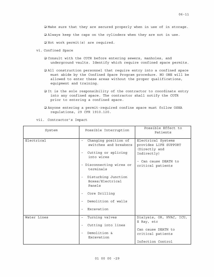
Make sure that they are secured properly when in use of in storage.
Always keep the caps on the cylinders when they are not in use.
Hot work permit(s) are required.
vi. Confined Space
Consult with the COTR before entering sewers, manholes, and underground vaults. Identify which require confined space permits.
All construction personnel that require entry into a confined space must abide by the Confined Space Program procedure. NO ONE will be allowed to enter these areas without the proper qualifications, equipment and training.
It is the sole responsibility of the contractor to coordinate entry into any confined space. The contractor shall notify the COTR prior to entering a confined space.
Anyone entering a permit-required confine space must follow OSHA regulations, 29 CFR 1910.120.
vii. Contractor’s Impact
System Possible Interruption Possible Effect to Patients
Electrical - Changing position of switches and breakers
- Cutting or splicing into wires
- Disconnecting wires or terminals
- Disturbing Junction Boxes/Electrical Panels
- Core Drilling
- Demolition of walls
- Excavation
Electrical Systems provides LIFE SUPPORT (Directly and Indirectly)
- Can cause DEATH to critical patients
Water Lines - Turning valves
- Cutting into lines
- Demolition & Excavation
Dialysis, OR, HVAC, ICU, X Ray, etc
Can cause DEATH to critical patients
Infection Control
06-11
01 00 00 -30
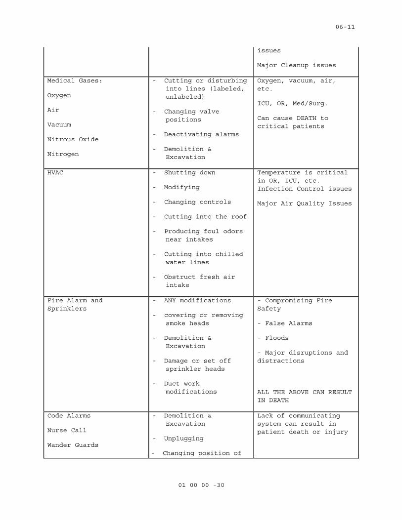
issues
Major Cleanup issues
Medical Gases:
Oxygen
Air
Vacuum
Nitrous Oxide
Nitrogen
- Cutting or disturbing into lines (labeled, unlabeled)
- Changing valve positions
- Deactivating alarms
- Demolition & Excavation
Oxygen, vacuum, air, etc.
ICU, OR, Med/Surg.
Can cause DEATH to critical patients
HVAC - Shutting down
- Modifying
- Changing controls
- Cutting into the roof
- Producing foul odors near intakes
- Cutting into chilled water lines
- Obstruct fresh air intake
Temperature is critical in OR, ICU, etc. Infection Control issues
Major Air Quality Issues
Fire Alarm and Sprinklers
- ANY modifications
- covering or removing smoke heads
- Demolition & Excavation
- Damage or set off sprinkler heads
- Duct work modifications
- Compromising Fire Safety
- False Alarms
- Floods
- Major disruptions and distractions
ALL THE ABOVE CAN RESULT IN DEATH
Code Alarms
Nurse Call
Wander Guards
- Demolition & Excavation
- Unplugging
- Changing position of
Lack of communicating system can result in patient death or injury

06-11
01 00 00 -31
switches/breakers
viii. Contractor Room/Space
Materials will be kept on the job site in the contractors’ room or in storage space provided for the contractor by the COTR.
Any shared space within the storage room(s) must be accessible to the COTR, Police, and Fire Department.
Corridors are not to be used for storage.
Contractors will manage the signed space and assure the site is kept clean and safe. Refer to OSHA standards.
Any disputes or concerns will be directed to the COTR.
ix. Damage by Contractors
Any damage caused by the contractor’s employees is to be reported to the COTR immediately.
x. Deliveries
All material deliveries at the loading dock must be coordinated with the COTR. Deliveries of material and equipment are to be made at times when the contractor or subcontractor is available to accept them. The VA will not be responsible for receiving or storing items, and warehouse personnel will not allow deliveries to be unloaded.
In order to minimize delays and interferences, large deliveries must occur Monday through Friday after 7:30 a.m. and before 2:30 p.m. No weekend and after hours deliveries to the VA loading dock.
xi. Dress Code
All personnel must be appropriately dressed for their work. T-shirts or garments with obscene or suggestive messages are not permitted. Personnel found improperly dressed will be asked to leave the facility.
xii. Dust Barriers and Ventilation Requirements
All dust barriers will be coordinated with the COTR before installation.
Dust barriers are needed to protect occupied areas on any portion of the construction project that has the potential to generate dust.
The barriers must be smoke resistive and non-combustible. When barriers are part of a smoke or fire barrier, the construction barriers must be equivalent.
06-11
01 00 00 -32
xiii. Emergency Preparedness Notification
Contractors are to post the “VA Emergency Guidebook” in a conspicuous spot for all construction personnel to review. Contraction personnel are to be trained on the postings prior to beginning work and as the project progresses.
The guidebook lists all emergency phone number and explains what to do in the case of an emergency. Such as; bomb threat, workplace injuries, emergency preparedness, hazardous materials & spills, tornado procedures, fire plan, and utility & equipment failures. A copy of the guidebook is available from the COTR.
xiv. Elevator Usage
Contractors shall not hold or block from use any public elevators in any building unless authorized by the COTR.
The COTR will define which elevators shall be used and the times for moving materials and waste to and from the site(s).
xv. Equipment Safety
Ladders are not to be left unattended in public areas during breaks and lunch hours. Ladders shall be laid down and placed out of the traffic areas during these periods.
No tools, carts, ladders or other equipment are to be left unattended outside a secured area.
Yellow safety barricades must be used when working in public areas.
Use of hospital equipment is not permitted.
xvi. Equipment and Supplies
Caution must be used with all flammable materials, i.e., adhesives, thinners, varnishes, etc.
All paint shall be low odor latex paint. The contractor will use odor reducing agents in all paints and solvents. Ventilation will be required if toxic or foul smelling materials have to be applied.
Only a one-day supply of paints, materials and gas cylinders is permitted outside an approved storage area.
xvii. Fire Alarm System
Care must be exercised to prevent the accidental tripping of smoke detectors and fire alarms.
Notify the COTR of your activities and location while performing work in the hospital.
06-11
01 00 00 -33
Cover and protect the smoke alarms when raising dust or creating smoke. Remove plastic bags around smoke detectors upon completion of the work and at the end of each workday.
Notify the COTR immediately if the alarm is tripped.
xviii. Hazardous Materials and Waste
A listing of all hazardous materials that will be used on the job and their material safety data sheets (MSDS) will be available on site for COTR review.
Ant excess or used chemicals will be removed from the hospital promptly and properly disposed of by the contractor in accordance with federal, state and local regulations.
Do not store excessive amounts of flammable or combustible materials on the job site. A safe location to store these materials will be provided by the COTR.
xix. Heavy Lifting
Hoisting heavy materials/items require prior review by the COTR.
xx. Hospital Fire Plan R-A-C-E
Fire Plan - There is no difference between a fire drill and an actual fire.
Make sure you know where the pull stations are in the areas you are working.
If you are in the area of the fire:
R Rescue anyone from the area if necessary
A Pull the nearest Pull Station
C Contain the fire by closing all doors in the area
E Extinguish if possible or Evacuate the area immediately
If you are NOT in the area of the fire:
Construction Workers are to cease activities, stay in place, and wait for further instructions or cancellation of the fire drill.
DO NOT move through the hospital. DO NOT use the elevators or stairwells.
xxi. Housekeeping
Housekeeping in public areas of the hospital will be maintained at the highest level, even while work is ongoing.
06-11
01 00 00 -34
In secured areas, housekeeping will be performed as needed, but at a minimum at the end of each day.
xxii. Hot Work and Above Ceiling Permits
Before any cutting, soldering, grinding, welding, etc., is conducted, the contractor or sub-contractor shall obtain permission through a hot work permit. The contractor shall be responsible for obtaining the hot work permits from the COTR.
Gas and oxygen canisters shall be properly chained and protected and two 10 – pound fire extinguishers shall be present.
The contractor shall maintain a fire watch during the hot work operations, and 30 minutes after the hot work is completed.
Prior to performing any work within 10 feet of a fire wall or smoke partition/wall, the contractor shall obtain permission through a above ceiling work permit issued by the COTR.
xxiii. Identification Badges
The construction personnel will be required to wear VA Contractor Identification Badges.
xxiv. Infection Control
Prior to all construction activities, infection control procedures must be review and approved by the COTR.
The construction personnel are to read and follow the directions listed on any Infection Control Precaution sheet posted outside a patient’s room. Generally, this means permission must be obtained from the nursing staff before entry.
Temporary walls or dust barriers are required to enclose areas under construction.
Under some conditions, it may be necessary to block return and supply ducts. There shall be no re-circulation of air from a construction area that will generate dust, smoke or odors to other parts of the hospital.
Tack pads must be located entrances and exits to the construction area.
Contractor shall promptly remove any dust tracked outside of construction barriers.
As a standard precaution assume that any person may carry contagious disease. In order to protect you from these diseases always assume blood; non-intact skin, mucous membranes and other body fluids and excretions are infectious. Do not touch any such materials but contact the COTR immediately. Needle container boxes are provided for the disposal of syringes and other sharps used in
06-11
01 00 00 -35
the medical center. These must be properly removed and disposed of by hospital personnel.
xxv. Interim Life Safety
The hospital will document whether and to what extent Interim Life Safety Measures (ILSM) will be implemented for each project.
Any life safety code violations incurred during construction or renovation will result in close coordination with COTR to implement the hospital’s Interim Life Safety Measures. JCAHO and NFPA require these measures.
The Contractor in cooperation with the COTR will ensure ILSMs are employed to temporarily compensate for hazards posed by existing Life Safety Code (LSC) deficiencies or construction activities.
ILSMs apply to both construction and hospital employees.
ILSMs will require increased walkthrough and inspections by the superintendent/foreman, COTR and Safety Officer. A daily interim life safety measure inspection report will be provided to the contractor at the preconstruction meeting.
Training of construction workers and hospital staff will always be a significant part of nay ILSM procedure. The contractor, COTR and Safety Official all share responsibility to make sure everyone under increased risk is made aware of the risk and compensating ILSMs.
xxvi. Life Safety
Temporary construction partitions of non-combustible materials shall be installed as required to provide a smoke tight separation between the areas undergoing renovation and/or construction and adjoining areas that are occupied by the facility.
Exits for occupied areas of the building including rooms, suites, corridors and floors shall not be blocked by the construction or by construction materials. Exit may be blocked temporarily if it is unavoidable and adequate alternative measures are provided, such as signage, instructions to occupants and approved by the COTR.
Existing fire protection systems including fire alarm systems, smoke detection systems, and sprinkler systems shall not be altered except as required for the alteration and/or renovation project. Any alteration to the system shall be coordinated with COTR
It is the responsibility of each contractor to know exactly where the fire extinguishers and pull stations are in the work area.
06-11
01 00 00 -36
Fire hazard inspections shall be conducted daily by the contractor once construction starts and until the work is turned back over to the facility.
All temporary electrical wiring and equipment used for construction shall be installed and used in accordance with pertinent provisions of NFPA 70 and National Electrical Code.
Maintain construction site to permit access to fire department as necessary. Clear building construction areas of obstructions so that all portions are accessible for fire department apparatus and permit emergency egress of patients and other personnel.
xxvii. Lockout/Tag out
Lock Out/Tag Out - No contract workers is allowed to change the status/position of ANY switch, valve or any other energy source without prior approval from the COTR. All Lock out/Tag out activities need prior approval before implementation. Any activity requiring a Lockout/Tag out process must comply with the hospital policy.
All contractors shall comply with OSHA Regulation 29 CFR 1910.147 on Lockout/Tag out procedures.
Only VA personnel are authorized to shutdown hospital equipment or utilities unless permission is specifically granted.
xxviii. Material Safety Data Sheets (MSDS)
MSDS must be provided for any hazardous materials that will be used on VA property.
MSDS are available for all materials used in the hospital. Contact the COTR for all hospital MSDSs.
xxix. Noise
All core drilling, chipping and hole drilling shall be done at a time and day determined by the COTR in consultation with occupants of the space and adjacent areas.
Patients, visitors and staff deserve consideration and the quiet enjoyment of their premises. Anyone found being loud, rude or otherwise annoying to the patients, their guests or hospital staff would be asked to leave the hospital.
All work activity within occupied portions of the hospital shall be accomplished with minimal disruption to the patients, physicians, visitors and staff.
Playing of radios, tapes and CD players is not permitted in any occupied area. “Walkman” radios/tapes and CD players are not permitted anywhere in the hospital.
06-11
01 00 00 -37
The playing of radios, tapes and CD players are permitted in vacant areas but shall not be heard outside the vacant area.
xxx. OSHA Compliance
All contractors are subject to Occupational Safety and Health Administration (OSHA) regulations. The contractor is expected to enforce and comply with these standards in the performance of their work. OSHA regulations can be found in Chapter 29 of the Code of Federal Regulations (CFR). Failure on the part of any contractor or their employee to comply with these standards and/or conduct their work in a safe fashion will result in an interruption in the work schedule for which the contractor will be solely responsible.
xxxi. Parking
COTR will designate contractor employee parking areas. Contractors may not block fire lanes or other roadways.
Contractor to coordinate parking and obtain parking permits from the COTR.
xxxii. Patient/Visitor Privacy
No construction personnel are allowed to review, acknowledge or move any patient information or records.
xxxiii. Personal Protective Equipment
Many situations require specific personal protective equipment for worker safety according to OSHA. It is the responsibility of the individual contractor to know when it is to be used and is responsible to wear them.
xxxiv. Posting and Training
The field superintendents/foremen are to post the following hospital specific documents for all construction employees to read; Construction Commandments, VA Emergency Guidebook and Hospital Smoking Policy.
Each field superintendent/foreman is responsible for construction personnel working under his/her supervision. This person shall make sure each employee working on the site has been trained on the Construction Commandments; as well as, other posted information.
xxxv. Restroom Usage
Construction personnel shall use the public restrooms and shall not use restrooms in occupied areas.
xxxvi. Request for Information
06-11
01 00 00 -38
All requests for assistance, coordination and information shall be done through the COTR.
Address: COTR (Engineering Service)
Wm. S. Middleton Memorial VA Hospital
2500 Overlook Terrace
Madison, WI 53705
Phone No. (608)280-7040
Fax No. (608)280-7186
xxxvii. Safety Regulations
Contractors are expected to comply with all Occupational Safety and Health Administration (OSHA) regulation, 29 CFR 1926 and 1910.
Appropriate job signs and barriers are in place to prevent occupants from straying into the construction area.
Stairwell doors cannot be propped open or blocked at any time. Equipment cannot be stored in the stairwells.
All contractors shall close doors to construction area. All doors shall be locked when not under contractor direct supervision.
All contractors are encouraged to frequently review these guidelines with their employees and subcontractors on site (e.g., during weekly Tool Box Safety Meetings).
All contractors and their subcontractors are responsible for complying with these guidelines, specification section 01 00 00 , and OSHA rules and regulations.
xxxviii. Security of Construction Areas
Before beginning work or a project, all contractors shall check in with the COTR. The contractor will supply the following information: scope of work, authorization, duration, and any pertinent information that is required.
Contractor to use VA supplied locks; cylinders and keys allowing access to the construction area.
The COTR, Facilities Engineering, Safety Office and Police must have be able to access the construction area as needed to perform their assigned responsibilities.
Two evacuation routes from the worksite must be maintained at all times.
Contractors may lock up their personnel tools, etc., with personal locks.
06-11
01 00 00 -39
xxxix. Shutdowns/Connections to Utilities and Building Systems
All connections, tie-ins, or alterations to the building life safety components and utility systems must be performed with COTR coordination and approval at least one week prior to the date requested.
xl. Smoking
The hospital and campus are smoke free environments. Smoking is permitted only in two designated smoking shelters. All construction employees must comply with this policy. Any construction employee not complying with this policy will be asked to leave the facility grounds for the duration of the project.
Construction superintendents/foremen are expected to enforce this smoking policy.
xli. Stop Work
The hospital safety officer and the COTR have the Director’s authorization to stop work whenever conditions pose an imminent threat to life and health or threaten damage to equipment or buildings.
xlii. Subcontractors
The general contractor is responsible for obtaining and submitting signed “Field Supervisors/Foremen Agreement” from each of subcontractors working in the hospital. A subcontractor will not be paid until the COTR has received the signed agreements.
The COTR reserves the right to reject any subcontractor proposed or working on a project for just cause.
An on-site construction employee must be designated “In Charge” at all times the contractor is on site.
xliii. Traffic Control
Contractor shall provide trained personnel and equipment, signage, barricades, etc., to regulate traffic whenever construction operations affect traffic patterns.
xliv. Trenching and Digging
OSHA regulations must be followed during trenching operations.
xlv. Waste
Trash, combustible waste and excess construction materials must be removed daily to prevent accumulation. Contractors must arrange for the removal of their debris and waste with the COTR.
06-11
01 00 00 -40
Contractor shall use their Dumpster. Coordinate dumpster location with the COTR.
The contractor is encouraged to recycle construction materials. Refer to specification Section 01 74 19, CONSTRUCTION WASTE MANAGEMENT for specific requirements.
The contractor is expected to comply with all environmental regulations.
xlvi. Wall and Floor Penetrations
Prior to making any penetrations in walls, floors or ceilings, it is the contractor’s responsibility to identify fire and smoke rated systems.
The contractor shall have the COTR inspect and approve all floor and wall penetration.
All wall and floor penetrations must be located, marked and sealed by the contractor responsible for the penetration.
All repaired penetrations on rated systems must be completed using a fire rated material matching the rating of the system and must inspected by the COTR before ceiling tiles are replaced or area is concealed.
IF THERE IS ANY QUESTION REGARDING ANY OF THE INFORMATION ON THIS DOCUMENT,
IMMEDIATELY CONTACT THE COTR TO RESOLVE ISSUES PRIOR TO WORK COMMENCEMENT.
Company:
Receipt Acknowledged:
Signature:
Date:
Return signed copy to VA Project Manager.
- - - E N D - - -
04-10M
01 32 16.15 - 1
SECTION 01 32 16.15PROJECT SCHEDULES
PART 1- GENERAL
1.1 DESCRIPTION:
A. The Contractor shall develop a Critical Path Method (CPM) plan and
schedule demonstrating fulfillment of the contract requirements (Project
Schedule), and shall keep the Project Schedule up-to-date in accordance
with the requirements of this section and shall utilize the plan for
scheduling, coordinating and monitoring work under this contract
(including all activities of subcontractors, equipment vendors and
suppliers). Conventional Critical Path Method (CPM) technique shall be
utilized to satisfy both time and cost applications.
1.2 CONTRACTOR'S REPRESENTATIVE:
A. The Contractor shall designate an authorized representative responsible
for the Project Schedule including preparation, review and progress
reporting with and to the Contracting Officer's Representative (COR).
B. The Contractor's representative shall have direct project control and
complete authority to act on behalf of the Contractor in fulfilling the
requirements of this specification section.
C. The Contractor’s representative shall have the option of developing the
project schedule within their organization or to engage the services of
an outside consultant. If an outside scheduling consultant is utilized,
Section 1.3 of this specification will apply.
1.3 CONTRACTOR'S CONSULTANT:
A. The Contractor shall submit a qualification proposal to the COR, within
10 days of bid acceptance. The qualification proposal shall include:
1. The name and address of the proposed consultant.
2. Information to show that the proposed consultant has the
qualifications to meet the requirements specified in the preceding
paragraph.
3. A representative sample of prior construction projects, which the
proposed consultant has performed complete project scheduling
services. These representative samples shall be of similar size and
scope.
B. The Contracting Officer has the right to approve or disapprove the
proposed consultant, and will notify the Contractor of the VA decision
within seven calendar days from receipt of the qualification proposal.
In case of disapproval, the Contractor shall resubmit another consultant
04-10M
01 32 16.15 - 2
within 10 calendar days for renewed consideration. The Contractor shall
have their scheduling consultant approved prior to submitting any
schedule for approval.
1.4 COMPUTER PRODUCED SCHEDULES
A. The contractor shall provide monthly, to the Department of Veterans
Affairs (VA), all computer-produced time/cost schedules and reports
generated from monthly project updates. This monthly computer service
will include: three copies of up to five different reports (inclusive of
all pages) available within the user defined reports of the scheduling
software approved by the Contracting Officer; a hard copy listing of all
project schedule changes, and associated data, made at the update and an
electronic file of this data; and the resulting monthly updated schedule
in PDM format. These must be submitted with and substantively support
the contractor’s monthly payment request and the signed look ahead
report. The COR shall identify the five different report formats that
the contractor shall provide.
B. The contractor shall be responsible for the correctness and timeliness
of the computer-produced reports. The Contractor shall also responsible
for the accurate and timely submittal of the updated project schedule
and all CPM data necessary to produce the computer reports and payment
request that is specified.
C. The VA will report errors in computer-produced reports to the
Contractor’s representative within ten calendar days from receipt of
reports. The Contractor shall reprocess the computer-produced reports
and associated diskette(s), when requested by the Contracting Officer’s
representative, to correct errors which affect the payment and schedule
for the project.
1.5 THE COMPLETE PROJECT SCHEDULE SUBMITTAL
A. Within 45 calendar days after receipt of Notice to Proceed, the
Contractor shall submit for the Contracting Officer's review; three blue
line copies of the interim schedule on sheets of paper 765 x 1070 mm (30
x 42 inches) and an electronic file in the previously approved CPM
schedule program. The submittal shall also include three copies of a
computer-produced activity/event ID schedule showing project duration;
phase completion dates; and other data, including event cost. Each
activity/event on the computer-produced schedule shall contain as a
minimum, but not limited to, activity/event ID, activity/event
description, duration, budget amount, early start date, early finish
date, late start date, late finish date and total float. Work
activity/event relationships shall be restricted to finish-to-start or
04-10M
01 32 16.15 - 3
start-to-start without lead or lag constraints. Activity/event date
constraints, not required by the contract, will not be accepted unless
submitted to and approved by the Contracting Officer. The contractor
shall make a separate written detailed request to the Contracting
Officer identifying these date constraints and secure the Contracting
Officer’s written approval before incorporating them into the network
diagram. The Contracting Officer’s separate approval of the Project
Schedule shall not excuse the contractor of this requirement. Logic
events (non-work) will be permitted where necessary to reflect proper
logic among work events, but must have zero duration. The complete
working schedule shall reflect the Contractor's approach to scheduling
the complete project. The final Project Schedule in its original form
shall contain no contract changes or delays which may have been incurred
during the final network diagram development period and shall reflect
the entire contract duration as defined in the bid documents. These
changes/delays shall be entered at the first update after the final
Project Schedule has been approved. The Contractor should provide their
requests for time and supporting time extension analysis for contract
time as a result of contract changes/delays, after this update, and in
accordance with Article, ADJUSTMENT OF CONTRACT COMPLETION.
D. Within 30 calendar days after receipt of the complete project interim
Project Schedule and the complete final Project Schedule, the
Contracting Officer or his representative, will do one or both of the
following:
1. Notify the Contractor concerning his actions, opinions, and
objections.
2. A meeting with the Contractor at or near the job site for joint
review, correction or adjustment of the proposed plan will be
scheduled if required. Within 14 calendar days after the joint
review, the Contractor shall revise and shall submit three blue line
copies of the revised Project Schedule, three copies of the revised
computer-produced activity/event ID schedule and a revised electronic
file as specified by the Contracting Officer. The revised submission
will be reviewed by the Contracting Officer and, if found to be as
previously agreed upon, will be approved.
E. The approved baseline schedule and the computer-produced schedule(s)
generated there from shall constitute the approved baseline schedule
until subsequently revised in accordance with the requirements of this
section.
04-10M
01 32 16.15 - 4
F. The Complete Project Schedule shall contain approximately 100 work
activities/events.
1.6 WORK ACTIVITY/EVENT COST DATA
A. The Contractor shall cost load all work activities/events except
procurement activities. The cumulative amount of all cost loaded work
activities/events (including alternates) shall equal the total contract
price. Prorate overhead, profit and general conditions on all work
activities/events for the entire project length. The contractor shall
generate from this information cash flow curves indicating graphically
the total percentage of work activity/event dollar value scheduled to be
in place on early finish, late finish. These cash flow curves will be
used by the Contracting Officer to assist him in determining approval or
disapproval of the cost loading. Negative work activity/event cost data
will not be acceptable, except on VA issued contract changes.
C. In accordance with FAR 52.236 – 1 (PERFORMANCE OF WORK BY THE
CONTRACTOR) and VAAR 852.236 – 72 (PERFORMANCE OF WORK BY THE
CONTRACTOR), the Contractor shall submit, simultaneously with the cost
per work activity/event of the construction schedule required by this
Section, a responsibility code for all activities/events of the project
for which the Contractor's forces will perform the work.
1.7 PROJECT SCHEDULE REQUIREMENTS
A. Show on the project schedule the sequence of work activities/events
required for complete performance of all items of work. The Contractor
Shall:
1. Show activities/events as:
a. Contractor's time required for submittal of shop drawings,
templates, fabrication, delivery and similar pre-construction
work.
b. Contracting Officer's and Architect-Engineer's review and approval
of shop drawings, equipment schedules, samples, template, or
similar items.
04-10M
01 32 16.15 - 5
c. Interruption of VA Facilities utilities, delivery of Government
furnished equipment, and rough-in drawings, project phasing and
any other specification requirements.
d. Test, balance and adjust various systems and pieces of equipment,
maintenance and operation manuals, instructions and preventive
maintenance tasks.
e. VA inspection and acceptance activity/event with a minimum
duration of five work days at the end of each phase and
immediately preceding any VA move activity/event required by the
contract phasing for that phase.
2. Show not only the activities/events for actual construction work for
each trade category of the project, but also trade relationships to
indicate the movement of trades from one area, floor, or building, to
another area, floor, or building, for at least five trades who are
performing major work under this contract.
3. Break up the work into activities/events of a duration no longer than
20 work days each or one reporting period, except as to non-
construction activities/events (i.e., procurement of materials,
delivery of equipment, concrete and asphalt curing) and any other
activities/events for which the COR may approve the showing of a
longer duration. The duration for VA approval of any required
submittal, shop drawing, or other submittals will not be less than 20
work days.
4. Describe work activities/events clearly, so the work is readily
identifiable for assessment of completion. Activities/events labeled
"start," "continue," or "completion," are not specific and will not
be allowed. Lead and lag time activities will not be acceptable.
5. The schedule shall be generally numbered in such a way to reflect
either discipline, phase or location of the work.
B. The Contractor shall submit the following supporting data in addition to
the project schedule:
1. The appropriate project calendar including working days and holidays.
2. The planned number of shifts per day.
3. The number of hours per shift.
Failure of the Contractor to include this data shall delay the review of
the submittal until the Contracting Officer is in receipt of the missing
data.
C. To the extent that the Project Schedule or any revised Project Schedule
shows anything not jointly agreed upon, it shall not be deemed to have
been approved by the COR. Failure to include any element of work
04-10M
01 32 16.15 - 6
required for the performance of this contract shall not excuse the
Contractor from completing all work required within any applicable
completion date of each phase regardless of the COR’s approval of the
Project Schedule.
D. Compact Disk Requirements and CPM Activity/Event Record Specifications:
Submit to the VA an electronic file(s) containing one file of the data
required to produce a schedule, reflecting all the activities/events of
the complete project schedule being submitted.
1.8 PAYMENT TO THE CONTRACTOR:
A. Monthly, the contractor shall submit the AIA application and certificate
for payment documents G702 & G703 reflecting updated schedule activities
and cost data in accordance with the provisions of the following
Article, PAYMENT AND PROGRESS REPORTING, as the basis upon which
progress payments will be made pursuant to Article, FAR 52.232 – 5
(PAYMENT UNDER FIXED-PRICE CONSTRUCTION CONTRACTS) and VAAR 852.236 – 83
(PAYMENT UNDER FIXED-PRICE CONSTRUCTION CONTRACTS). The Contractor shall
be entitled to a monthly progress payment upon approval of estimates as
determined from the currently approved updated project schedule. Monthly
payment requests shall include: a listing of all agreed upon project
schedule changes and associated data; and an electronic file (s) of the
resulting monthly updated schedule.
B. Approval of the Contractor’s monthly Application for Payment shall be
contingent, among other factors, on the submittal of a satisfactory
monthly update of the project schedule.
1.9 PAYMENT AND PROGRESS REPORTING
A. Monthly schedule update meetings will be held on dates mutually agreed
to by the COR and the Contractor. Contractor and their CPM consultant
(if applicable) shall attend all monthly schedule update meetings. The
Contractor shall accurately update the Project Schedule and all other
data required and provide this information to the COR three work days in
advance of the schedule update meeting. Job progress will be reviewed to
verify:
1. Actual start and/or finish dates for updated/completed
activities/events.
2. Remaining duration for each activity/event started, or scheduled to
start, but not completed.
3. Logic, time and cost data for change orders, and supplemental
agreements that are to be incorporated into the Project Schedule.

04-10M
01 32 16.15 - 7
4. Changes in activity/event sequence and/or duration which have been
made, pursuant to the provisions of following Article, ADJUSTMENT OF
CONTRACT COMPLETION.
5. Completion percentage for all completed and partially completed
activities/events.
6. Logic and duration revisions required by this section of the
specifications.
7. Activity/event duration and percent complete shall be updated
independently.
B. After completion of the joint review, the contractor shall generate an
updated computer-produced calendar-dated schedule and supply the
Contracting Officer’s representative with reports in accordance with the
Article, COMPUTER PRODUCED SCHEDULES, specified.
C. After completing the monthly schedule update, the contractor’s
representative or scheduling consultant shall rerun all current period
contract change(s) against the prior approved monthly project schedule.
The analysis shall only include original workday durations and schedule
logic agreed upon by the contractor and COR for the contract change(s).
When there is a disagreement on logic and/or durations, the Contractor
shall use the schedule logic and/or durations provided and approved by
the COR. After each rerun update, the resulting electronic project
schedule data file shall be appropriately identified and submitted to
the VA in accordance to the requirements listed in articles 1.4 and 1.7.
This electronic submission is separate from the regular monthly project
schedule update requirements and shall be submitted to the COR within
fourteen (14) calendar days of completing the regular schedule update.
Before inserting the contract changes durations, care must be taken to
ensure that only the original durations will be used for the analysis,
not the reported durations after progress. In addition, once the final
network diagram is approved, the contractor must recreate all manual
progress payment updates on this approved network diagram and associated
reruns for contract changes in each of these update periods as outlined
above for regular update periods. This will require detailed record
keeping for each of the manual progress payment updates.
D. Following approval of the CPM schedule, the VA, the General Contractor,
its approved CPM Consultant, PE office representatives, and all
subcontractors needed, as determined by the SRE, shall meet to discuss
the monthly updated schedule. The main emphasis shall be to address work
activities to avoid slippage of project schedule and to identify any
04-10M
01 32 16.15 - 8
necessary actions required to maintain project schedule during the
reporting period. The Government representatives and the Contractor
should conclude the meeting with a clear understanding of those work and
administrative actions necessary to maintain project schedule status
during the reporting period. This schedule coordination meeting will
occur after each monthly project schedule update meeting utilizing the
resulting schedule reports from that schedule update. If the project is
behind schedule, discussions should include ways to prevent further
slippage as well as ways to improve the project schedule status, when
appropriate.
1.10 RESPONSIBILITY FOR COMPLETION
A. If it becomes apparent from the current revised monthly progress
schedule that phasing or contract completion dates will not be met, the
Contractor shall execute some or all of the following remedial actions:
1. Increase construction manpower in such quantities and crafts as
necessary to eliminate the backlog of work.
2. Increase the number of working hours per shift, shifts per working
day, working days per week, the amount of construction equipment, or
any combination of the foregoing to eliminate the backlog of work.
3. Reschedule the work in conformance with the specification
requirements.
B. Prior to proceeding with any of the above actions, the Contractor shall
notify and obtain approval from the COR for the proposed schedule
changes. If such actions are approved, the representative schedule
revisions shall be incorporated by the Contractor into the Project
Schedule before the next update, at no additional cost to the
Government.
1.11 CHANGES TO THE SCHEDULE
A. Within 30 calendar days after VA acceptance and approval of any updated
project schedule, the Contractor shall submit a revised electronic file
(s) and a list of any activity/event changes including predecessors and
successors for any of the following reasons:
1. Delay in completion of any activity/event or group of
activities/events, which may be involved with contract changes,
strikes, unusual weather, and other delays will not relieve the
Contractor from the requirements specified unless the conditions are
shown on the CPM as the direct cause for delaying the project beyond
the acceptable limits.
2. Delays in submittals, or deliveries, or work stoppage are encountered
which make rescheduling of the work necessary.
3. The schedule does not represent the actual prosecution and progress
04-10M
01 32 16.15 - 9
of the project.
4. When there is, or has been, a substantial revision to the
activity/event costs regardless of the cause for these revisions.
B. CPM revisions made under this paragraph which affect the previously
approved computer-produced schedules for Government furnished equipment,
vacating of areas by the VA Facility, contract phase(s) and sub
phase(s), utilities furnished by the Government to the Contractor, or
any other previously contracted item, shall be furnished in writing to
the Contracting Officer for approval.
C. Contracting Officer's approval for the revised project schedule and all
relevant data is contingent upon compliance with all other paragraphs of
this section and any other previous agreements by the Contracting
Officer or the VA representative.
D. The cost of revisions to the project schedule resulting from contract
changes will be included in the proposal for changes in work as
specified in FAR 52.243 – 4 (Changes) and VAAR 852.236 – 88 (Changes –
Supplemental), and will be based on the complexity of the revision or
contract change, man hours expended in analyzing the change, and the
total cost of the change.
E. The cost of revisions to the Project Schedule not resulting from
contract changes is the responsibility of the Contractor.
1.12 ADJUSTMENT OF CONTRACT COMPLETION
A. The contract completion time will be adjusted only for causes specified
in this contract. Request for an extension of the contract completion
date by the Contractor shall be supported with a justification, CPM data
and supporting evidence as the COR may deem necessary for determination
as to whether or not the Contractor is entitled to an extension of time
under the provisions of the contract. Submission of proof based on
revised activity/event logic, durations (in work days) and costs is
obligatory to any approvals. The schedule must clearly display that the
Contractor has used, in full, all the float time available for the work
involved in this request. The Contracting Officer's determination as to
the total number of days of contract extension will be based upon the
current computer-produced calendar-dated schedule for the time period in
question and all other relevant information.
B. Actual delays in activities/events which, according to the computer-
produced calendar-dated schedule, do not affect the extended and
predicted contract completion dates shown by the critical path in the
network, will not be the basis for a change to the contract completion
04-10M
01 32 16.15 - 10
date. The Contracting Officer will within a reasonable time after
receipt of such justification and supporting evidence, review the facts
and advise the Contractor in writing of the Contracting Officer's
decision.
C. The Contractor shall submit each request for a change in the contract
completion date to the Contracting Officer in accordance with the
provisions specified under FAR 52.243 – 4 (Changes) and VAAR 852.236 –
88 (Changes – Supplemental). The Contractor shall include, as a part of
each change order proposal, a sketch showing all CPM logic revisions,
duration (in work days) changes, and cost changes, for work in question
and its relationship to other activities on the approved network
diagram.
D. All delays due to non-work activities/events such as RFI’s, WEATHER,
STRIKES, and similar non-work activities/events shall be analyzed on a
month by month basis.
- - - E N D - - -
11-08M
01 33 23 - 1
SECTION 01 33 23 SHOP DRAWINGS, PRODUCT DATA, AND SAMPLES
1.1 Refer to Articles titled SPECIFICATIONS AND DRAWINGS FOR CONSTRUCTION
(FAR 52.236-21) and, SPECIAL NOTES (VAAR 852.236-91), in GENERAL
CONDITIONS.
1.2 For the purposes of this contract, samples , test reports, certificates,
and manufacturers' literature and data shall also be subject to the
previously referenced requirements. The following text refers to all
items collectively as SUBMITTALS.
1.3 Submit for approval, all of the items specifically mentioned under the
separate sections of the specification, with information sufficient to
evidence full compliance with contract requirements. Materials,
fabricated articles and the like to be installed in permanent work shall
equal those of approved submittals. After an item has been approved, no
change in brand or make will be permitted unless:
A. A. Satisfactory written evidence is presented to, and approved by
Contracting Officer, that manufacturer cannot make scheduled delivery of
approved item or;
B. B. Item delivered has been rejected and substitution of a suitable
item is an urgent necessity or;
C. C. Other conditions become apparent which indicates approval of such
substitute item to be in best interest of the Government.
1.4 Forward submittals in sufficient time to permit proper consideration and
approval action by Government. Time submission to assure adequate lead
time for procurement of contract - required items. Delays attributable
to untimely and rejected submittals will not serve as a basis for
extending contract time for completion.
1.5 Submittals will be reviewed for compliance with contract requirements by
Architect-Engineer, and action thereon will be taken by COR on behalf of
the Contracting Officer.
1.6 Upon receipt of submittals, Architect-Engineer will assign a file number
thereto. Contractor, in any subsequent correspondence, shall refer to
this file and identification number to expedite replies relative to
previously approved or disapproved submittals.
1.7 The Government reserves the right to require additional submittals,
whether or not particularly mentioned in this contract. If additional
11-08M
01 33 23 - 2
submittals beyond those required by the contract are furnished pursuant
to request therefor by Contracting Officer, adjustment in contract price
and time will be made in accordance with Articles titled CHANGES (FAR
52.243-4) and CHANGES - SUPPLEMENT (VAAR 852.236-88) of the GENERAL
CONDITIONS.
1.8 Schedules called for in specifications and shown on shop drawings shall
be submitted for use and information of Department of Veterans Affairs
and Architect-Engineer. However, the Contractor shall assume
responsibility for coordinating and verifying schedules. The Contracting
Officer and Architect- Engineer assumes no responsibility for checking
schedules or layout drawings for exact sizes, exact numbers and detailed
positioning of items.
1.9 Submittals must be submitted by Contractor only and shipped prepaid.
Contracting Officer assumes no responsibility for checking quantities or
exact numbers included in such submittals.
D. A. Submit shop drawings, schedules, manufacturers' literature and
data, and certificates in quadruplicate, except where a greater number
is specified.
E. B. Submittals will receive consideration only when covered by a
transmittal letter signed by Contractor. Letter shall be sent via first
class mail FAX or e-mail and shall contain the list of items, name of
Medical Center, name of Contractor, contract number, applicable
specification paragraph numbers, applicable drawing numbers (and other
information required for exact identification of location for each
item), manufacturer and brand, ASTM or Federal Specification Number (if
any) and such additional information as may be required by
specifications for particular item being furnished. In addition,
catalogs shall be marked to indicate specific items submitted for
approval.
1. 1. A copy of letter must be enclosed with items, and any items received without identification letter will be considered "unclaimed
goods" and held for a limited time only.
2. 2. Each sample, certificate, manufacturers' literature and data shall be labeled to indicate the name and location of the Medical Center,
name of Contractor, manufacturer, brand, contract number and ASTM or
Federal Specification Number as applicable and location(s) on
project.
11-08M
01 33 23 - 3
3. 3. Required certificates shall be signed by an authorized representative of manufacturer or supplier of material, and by
Contractor.
F. C. If submittal samples have been disapproved, resubmit new samples
as soon as possible after notification of disapproval. Such new samples
shall be marked "Resubmitted Sample" in addition to containing other
previously specified information required on label and in transmittal
letter.
G. D. Approved samples will be kept on file by the COR at the site until
completion of contract, at which time such samples will be delivered to
Contractor as Contractor's property. Where noted in technical sections
of specifications, approved samples in good condition may be used in
their proper locations in contract work. At completion of contract,
samples that are not approved will be returned to Contractor only upon
request and at Contractor's expense. Such request should be made prior
to completion of the contract. Disapproved samples that are not
requested for return by Contractor will be discarded after completion of
contract.
H. E. Submittal drawings (shop, erection or setting drawings) and
schedules, required for work of various trades, shall be checked before
submission by technically qualified employees of Contractor for
accuracy, completeness and compliance with contract requirements. These
drawings and schedules shall be stamped and signed by Contractor
certifying to such check.
1. 1. For each drawing required, submit one legible photographic paper or vellum reproducible.
2. 2. Reproducible shall be full size. 3. 3. Each drawing shall have marked thereon, proper descriptive title,
including Medical Center location, project number, manufacturer's
number, reference to contract drawing number, detail Section Number,
and Specification Section Number.
4. 4. A space 120 mm by 125 mm (4-3/4 by 5 inches) shall be reserved on each drawing to accommodate approval or disapproval stamp.
5. 5. Submit drawings, ROLLED WITHIN A MAILING TUBE, fully protected for shipment.
6. 6. One reproducible print of approved or disapproved shop drawings will be forwarded to Contractor.
7. 7. When work is directly related and involves more than one trade, shop drawings shall be submitted to Architect-Engineer under one
cover.
11-08M
01 33 23 - 4
1.10 Samples shop drawings, test reports, certificates and manufacturers'
literature and data, shall be submitted for approval to
IBC Engineering Services
(Architect-Engineer)
N8 W22195 Johnson Dr. Suite 180Waukesha, WI 53186
1.11 At the time of transmittal to the Architect-Engineer, the Contractor
shall also send a copy of the complete submittal directly to the COR.
- - - E N D - - -
09-11
01 42 19 - 1
SECTION 01 42 19 REFERENCE STANDARDS
PART 1 - GENERAL
1.1 DESCRIPTION
This section specifies the availability and source of references and
standards specified in the project manual under paragraphs APPLICABLE
PUBLICATIONS and/or shown on the drawings.
1.2 AVAILABILITY OF SPECIFICATIONS LISTED IN THE GSA INDEX OF FEDERAL
SPECIFICATIONS, STANDARDS AND COMMERCIAL ITEM DESCRIPTIONS FPMR PART 101-
29 (FAR 52.211-1) (AUG 1998)
A. The GSA Index of Federal Specifications, Standards and Commercial Item
Descriptions, FPMR Part 101-29 and copies of specifications, standards,
and commercial item descriptions cited in the solicitation may be
obtained for a fee by submitting a request to – GSA Federal Supply
Service, Specifications Section, Suite 8100, 470 East L’Enfant Plaza,
SW, Washington, DC 20407, Telephone (202) 619-8925, Facsimile (202) 619-
8978.
B. If the General Services Administration, Department of Agriculture, or
Department of Veterans Affairs issued this solicitation, a single copy
of specifications, standards, and commercial item descriptions cited in
this solicitation may be obtained free of charge by submitting a request
to the addressee in paragraph (a) of this provision. Additional copies
will be issued for a fee.
1.3 AVAILABILITY FOR EXAMINATION OF SPECIFICATIONS NOT LISTED IN THE GSA INDEX
OF FEDERAL SPECIFICATIONS, STANDARDS AND COMMERCIAL ITEM DESCRIPTIONS
(FAR 52.211-4) (JUN 1988)
The specifications and standards cited in this solicitation can be
examined at the following location:
DEPARMENT OF VETERANS AFFAIRS
Office of Construction & Facilities Management
Facilities Quality Service (00CFM1A)
425 Eye Street N.W, (sixth floor)
Washington, DC 20001
Telephone Numbers: (202) 632-5249 or (202) 632-5178
Between 9:00 AM - 3:00 PM
09-11
01 42 19 - 2
1.4 AVAILABILITY OF SPECIFICATIONS NOT LISTED IN THE GSA INDEX OF FEDERAL
SPECIFICATIONS, STANDARDS AND COMMERCIAL ITEM DESCRIPTIONS (FAR 52.211-3)
(JUN 1988)
The specifications cited in this solicitation may be obtained from the
associations or organizations listed below.
AA Aluminum Association Inc.
http://www.aluminum.org
AABC Associated Air Balance Council
http://www.aabchq.com
ACGIH American Conference of Governmental Industrial Hygienists
http://www.acgih.org
AGC Associated General Contractors of America
http://www.agc.org
AISC American Institute of Steel Construction
http://www.aisc.org
AISI American Iron and Steel Institute
http://www.steel.org
AMCA Air Movement and Control Association, Inc.
http://www.amca.org
ANSI American National Standards Institute, Inc.
http://www.ansi.org
ARI Air-Conditioning and Refrigeration Institute
http://www.ari.org
ASHRAE American Society of Heating, Refrigerating, and
Air-Conditioning Engineers
http://www.ashrae.org
ASME American Society of Mechanical Engineers
http://www.asme.org
ASSE American Society of Sanitary Engineering
http://www.asse-plumbing.org
ASTM American Society for Testing and Materials
http://www.astm.org
09-11
01 42 19 - 3
AWS American Welding Society
http://www.aws.org
EGSA Electrical Generating Systems Association
http://www.egsa.org
EEI Edison Electric Institute
http://www.eei.org
EPA Environmental Protection Agency
http://www.epa.gov
ETL ETL Testing Laboratories, Inc.
http://www.et1.com
FCC Federal Communications Commission
http://www.fcc.gov
FM Factory Mutual Insurance
http://www.fmglobal.com
GSA General Services Administration
http://www.gsa.gov
ICBO International Conference of Building Officials
http://www.icbo.org
ICEA Insulated Cable Engineers Association Inc.
http://www.icea.net
\ICAC Institute of Clean Air Companies
http://www.icac.com
IEEE Institute of Electrical and Electronics Engineers
http://www.ieee.org\
IPCEA Insulated Power Cable Engineers Association
MSS Manufacturers Standardization Society of the Valve and Fittings
Industry Inc.
http://www.mss-hq.com
NAPHCC Plumbing-Heating-Cooling Contractors Association
http://www.phccweb.org.org
09-11
01 42 19 - 4
NBS National Bureau of Standards
See - NIST
NEC National Electric Code
See - NFPA National Fire Protection Association
NEMA National Electrical Manufacturers Association
http://www.nema.org
NFPA National Fire Protection Association
http://www.nfpa.org
NIH National Institute of Health
http://www.nih.gov
NIST National Institute of Standards and Technology
http://www.nist.gov
OSHA Occupational Safety and Health Administration
Department of Labor
http://www.osha.gov
RMA Rubber Manufacturers Association, Inc.
http://www.rma.org
SMACNA Sheet Metal and Air-Conditioning Contractors
National Association, Inc.
http://www.smacna.org
SSPC The Society for Protective Coatings
http://www.sspc.org
TEMA Tubular Exchange Manufacturers Association
http://www.tema.org
UBC The Uniform Building Code
See ICBO
UL Underwriters' Laboratories Incorporated
http://www.ul.com
- - - E N D - - -
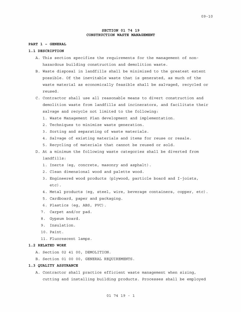
09-10
01 74 19 - 1
SECTION 01 74 19 CONSTRUCTION WASTE MANAGEMENT
PART 1 – GENERAL
1.1 DESCRIPTION
A. This section specifies the requirements for the management of non-
hazardous building construction and demolition waste.
B. Waste disposal in landfills shall be minimized to the greatest extent
possible. Of the inevitable waste that is generated, as much of the
waste material as economically feasible shall be salvaged, recycled or
reused.
C. Contractor shall use all reasonable means to divert construction and
demolition waste from landfills and incinerators, and facilitate their
salvage and recycle not limited to the following:
1. Waste Management Plan development and implementation.
2. Techniques to minimize waste generation.
3. Sorting and separating of waste materials.
4. Salvage of existing materials and items for reuse or resale.
5. Recycling of materials that cannot be reused or sold.
D. At a minimum the following waste categories shall be diverted from
landfills:
1. Inerts (eg, concrete, masonry and asphalt).
2. Clean dimensional wood and palette wood.
3. Engineered wood products (plywood, particle board and I-joists,
etc).
4. Metal products (eg, steel, wire, beverage containers, copper, etc).
5. Cardboard, paper and packaging.
6. Plastics (eg, ABS, PVC).
7. Carpet and/or pad.
8. Gypsum board.
9. Insulation.
10. Paint.
11. Fluorescent lamps.
1.2 RELATED WORK
A. Section 02 41 00, DEMOLITION.
B. Section 01 00 00, GENERAL REQUIREMENTS.
1.3 QUALITY ASSURANCE
A. Contractor shall practice efficient waste management when sizing,
cutting and installing building products. Processes shall be employed
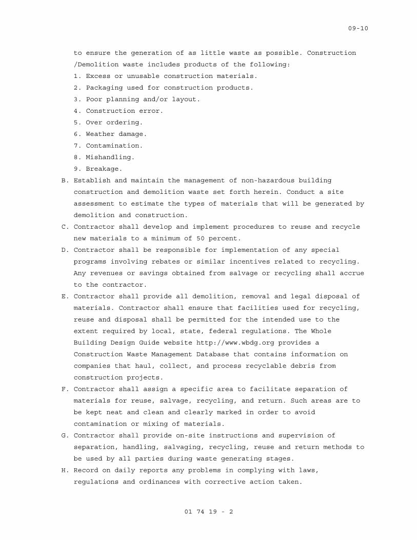
09-10
01 74 19 - 2
to ensure the generation of as little waste as possible. Construction
/Demolition waste includes products of the following:
1. Excess or unusable construction materials.
2. Packaging used for construction products.
3. Poor planning and/or layout.
4. Construction error.
5. Over ordering.
6. Weather damage.
7. Contamination.
8. Mishandling.
9. Breakage.
B. Establish and maintain the management of non-hazardous building
construction and demolition waste set forth herein. Conduct a site
assessment to estimate the types of materials that will be generated by
demolition and construction.
C. Contractor shall develop and implement procedures to reuse and recycle
new materials to a minimum of 50 percent.
D. Contractor shall be responsible for implementation of any special
programs involving rebates or similar incentives related to recycling.
Any revenues or savings obtained from salvage or recycling shall accrue
to the contractor.
E. Contractor shall provide all demolition, removal and legal disposal of
materials. Contractor shall ensure that facilities used for recycling,
reuse and disposal shall be permitted for the intended use to the
extent required by local, state, federal regulations. The Whole
Building Design Guide website http://www.wbdg.org provides a
Construction Waste Management Database that contains information on
companies that haul, collect, and process recyclable debris from
construction projects.
F. Contractor shall assign a specific area to facilitate separation of
materials for reuse, salvage, recycling, and return. Such areas are to
be kept neat and clean and clearly marked in order to avoid
contamination or mixing of materials.
G. Contractor shall provide on-site instructions and supervision of
separation, handling, salvaging, recycling, reuse and return methods to
be used by all parties during waste generating stages.
H. Record on daily reports any problems in complying with laws,
regulations and ordinances with corrective action taken.

09-10
01 74 19 - 3
1.4 TERMINOLOGY
A. Class III Landfill: A landfill that accepts non-hazardous resources
such as household, commercial and industrial waste resulting from
construction, remodeling, repair and demolition operations.
B. Clean: Untreated and unpainted; uncontaminated with adhesives, oils,
solvents, mastics and like products.
C. Construction and Demolition Waste: Includes all non-hazardous resources
resulting from construction, remodeling, alterations, repair and
demolition operations.
D. Dismantle: The process of parting out a building in such a way as to
preserve the usefulness of its materials and components.
E. Disposal: Acceptance of solid wastes at a legally operating facility
for the purpose of land filling (includes Class III landfills and inert
fills).
F. Inert Backfill Site: A location, other than inert fill or other
disposal facility, to which inert materials are taken for the purpose
of filling an excavation, shoring or other soil engineering operation.
G. Inert Fill: A facility that can legally accept inert waste, such as
asphalt and concrete exclusively for the purpose of disposal.
H. Inert Solids/Inert Waste: Non-liquid solid resources including, but not
limited to, soil and concrete that does not contain hazardous waste or
soluble pollutants at concentrations in excess of water-quality
objectives established by a regional water board, and does not contain
significant quantities of decomposable solid resources.
I. Mixed Debris: Loads that include commingled recyclable and non-
recyclable materials generated at the construction site.
J. Mixed Debris Recycling Facility: A solid resource processing facility
that accepts loads of mixed construction and demolition debris for the
purpose of recovering re-usable and recyclable materials and disposing
non-recyclable materials.
K. Permitted Waste Hauler: A company that holds a valid permit to collect
and transport solid wastes from individuals or businesses for the
purpose of recycling or disposal.
L. Recycling: The process of sorting, cleansing, treating, and
reconstituting materials for the purpose of using the altered form in
the manufacture of a new product. Recycling does not include burning,
incinerating or thermally destroying solid waste.
09-10
01 74 19 - 4
1. On-site Recycling – Materials that are sorted and processed on site
for use in an altered state in the work, i.e. concrete crushed for
use as a sub-base in paving.
2. Off-site Recycling – Materials hauled to a location and used in an
altered form in the manufacture of new products.
M. Recycling Facility: An operation that can legally accept materials for
the purpose of processing the materials into an altered form for the
manufacture of new products. Depending on the types of materials
accepted and operating procedures, a recycling facility may or may not
be required to have a solid waste facilities permit or be regulated by
the local enforcement agency.
N. Reuse: Materials that are recovered for use in the same form, on-site
or off-site.
O. Return: To give back reusable items or unused products to vendors for
credit.
P. Salvage: To remove waste materials from the site for resale or re-use
by a third party.
Q. Source-Separated Materials: Materials that are sorted by type at the
site for the purpose of reuse and recycling.
R. Solid Waste: Materials that have been designated as non-recyclable and
are discarded for the purposes of disposal.
S. Transfer Station: A facility that can legally accept solid waste for
the purpose of temporarily storing the materials for re-loading onto
other trucks and transporting them to a landfill for disposal, or
recovering some materials for re-use or recycling.
1.5 SUBMITTALS
A. In accordance with Section 01 33 23, SHOP DRAWINGS, PRODUCT DATA, and
SAMPLES, furnish the following:
B. Prepare and submit to the COR a written demolition debris management
plan. The plan shall include, but not be limited to, the following
information:
1. Procedures to be used for debris management.
2. Techniques to be used to minimize waste generation.
3. Analysis of the estimated job site waste to be generated:
a. List of each material and quantity to be salvaged, reused,
recycled.
b. List of each material and quantity proposed to be taken to a
landfill.

09-10
01 74 19 - 5
4. Detailed description of the Means/Methods to be used for material
handling.
a. On site: Material separation, storage, protection where
applicable.
b. Off site: Transportation means and destination. Include list of
materials.
1) Description of materials to be site-separated and self-hauled
to designated facilities.
2) Description of mixed materials to be collected by designated
waste haulers and removed from the site.
c. The names and locations of mixed debris reuse and recycling
facilities or sites.
d. The names and locations of trash disposal landfill facilities or
sites.
e. Documentation that the facilities or sites are approved to
receive the materials.
C. Designated Manager responsible for instructing personnel, supervising,
documenting and administer over meetings relevant to the Waste
Management Plan.
D. Monthly summary of construction and demolition debris diversion and
disposal, quantifying all materials generated at the work site and
disposed of or diverted from disposal through recycling.
1.6 APPLICABLE PUBLICATIONS
A. Publications listed below form a part of this specification to the
extent referenced. Publications are referenced by the basic designation
only. In the event that criteria requirements conflict, the most
stringent requirements shall be met.
B. U.S. Green Building Council (USGBC):
LEED Green Building Rating System for New Construction
1.7 RECORDS
A. Maintain records to document the quantity of waste generated; the
quantity of waste diverted through sale, reuse, or recycling; and the
quantity of waste disposed by landfill or incineration. Records shall
be kept in accordance with the LEED Reference Guide and LEED Template.
PART 2 - PRODUCTS
2.1 MATERIALS
A. List of each material and quantity to be salvaged, recycled, reused.
B. List of each material and quantity proposed to be taken to a landfill.
09-10
01 74 19 - 6
C. Material tracking data: Receiving parties, dates removed,
transportation costs, weight tickets, tipping fees, manifests,
invoices, net total costs or savings.
PART 3 - EXECUTION
3.1 COLLECTION
A. Provide all necessary containers, bins and storage areas to facilitate
effective waste management.
B. Clearly identify containers, bins and storage areas so that recyclable
materials are separated from trash and can be transported to respective
recycling facility for processing.
C. Hazardous wastes shall be separated, stored, disposed of according to
local, state, federal regulations.
3.2 DISPOSAL
A. Contractor shall be responsible for transporting and disposing of
materials that cannot be delivered to a source-separated or mixed
materials recycling facility to a transfer station or disposal facility
that can accept the materials in accordance with state and federal
regulations.
B. Construction or demolition materials with no practical reuse or that
cannot be salvaged or recycled shall be disposed of at a landfill or
incinerator.
3.3 REPORT
A. With each application for progress payment, submit a summary of
construction and demolition debris diversion and disposal including
beginning and ending dates of period covered.
B. Quantify all materials diverted from landfill disposal through salvage
or recycling during the period with the receiving parties, dates
removed, transportation costs, weight tickets, manifests, invoices.
Include the net total costs or savings for each salvaged or recycled
material.
C. Quantify all materials disposed of during the period with the receiving
parties, dates removed, transportation costs, weight tickets, tipping
fees, manifests, invoices. Include the net total costs for each
disposal.
- - - E N D - - -
06-10
02 41 00 - 1
SECTION 02 41 00 DEMOLITION
PART 1 - GENERAL
1.1 DESCRIPTION:
This section specifies demolition and removal of buildings, portions of
buildings, utilities, other structures and debris from trash dumps
shown.
1.2 RELATED WORK:
A. Safety Requirements: GENERAL CONDITIONS Article, ACCIDENT PREVENTION.
B. Disconnecting utility services prior to demolition: Section 01 00 00,
GENERAL REQUIREMENTS.
C. Reserved items that are to remain the property of the Government:
Section 01 00 00, GENERAL REQUIREMENTS.
D. Construction Waste Management: Section 017419 CONSTRUCTION WASTE
MANAGEMENT.
E. Infectious Control: Section 01 00 00, GENERAL REQUIREMENTS, Article 1.7,
INFECTION PREVENTION MEASURES.
1.3 PROTECTION:
A. Perform demolition in such manner as to eliminate hazards to persons and
property; to minimize interference with use of adjacent areas, utilities
and structures or interruption of use of such utilities; and to provide
free passage to and from such adjacent areas of structures. Comply with
requirements of GENERAL CONDITIONS Article, ACCIDENT PREVENTION.
B. Provide safeguards, including warning signs, barricades, temporary
fences, warning lights, and other similar items that are required for
protection of all personnel during demolition and removal operations.
Comply with requirements of Section 01 00 00, GENERAL REQUIREMENTS,
Article PROTECTION OF EXISTING VEGETATION, STRUCTURES, EQUIPMENT,
UTILITIES AND IMPROVEMENTS.
C. Prevent spread of flying particles and dust. Sprinkle rubbish and debris
with water to keep dust to a minimum. Do not use water if it results in
hazardous or objectionable condition such as, but not limited to; ice,
flooding, or pollution. Vacuum and dust the work area daily.
D. In addition to previously listed fire and safety rules to be observed in
performance of work, include following:
1. Wherever a cutting torch or other equipment that might cause a fire
is used, provide and maintain fire extinguishers nearby ready for
immediate use. Instruct all possible users in use of fire
extinguishers.
06-10
02 41 00 - 2
E. Before beginning any demolition work, the Contractor shall survey the
site and examine the drawings and specifications to determine the extent
of the work. The contractor shall take necessary precautions to avoid
damages to existing items to remain in place, to be reused, or to remain
the property of the Medical Center; any damaged items shall be repaired
or replaced as approved by the COR. The Contractor shall coordinate the
work of this section with all other work and shall construct and
maintain shoring, bracing, and supports as required. The Contractor
shall ensure that structural elements are not overloaded and shall be
responsible for increasing structural supports or adding new supports as
may be required as a result of any cutting, removal, or demolition work
performed under this contract. Do not overload structural elements.
Provide new supports and reinforcement for existing construction
weakened by demolition or removal works. Repairs, reinforcement, or
structural replacement must have COR’s approval.
PART 2 - PRODUCTS (NOT USED)
PART 3 – EXECUTION
3.1 DEMOLITION:
A. Completely demolish and remove construction as indicted or otherwise
required by renovation work.
B. Debris, including brick, concrete, stone, metals and similar materials
shall become property of Contractor and shall be disposed of by him
daily, off the Medical Center Property to avoid accumulation at the
demolition site. Materials that cannot be removed daily shall be stored
in areas specified by the COR. Contractor shall dispose debris in
compliance with applicable federal, state or local permits, rules and/or
regulations.
C. Remove existing utilities as indicated or uncovered by work and
terminate in a manner conforming to the nationally recognized code
covering the specific utility and approved by the COR. When Utility
lines are encountered that are not indicated on the drawings, the COR
shall be notified prior to further work in that area.
3.2 CLEAN-UP:
On completion of work of this section and after removal of all debris,
leave site in clean condition satisfactory to COR. Clean-up shall
include off the Medical Center disposal of all items and materials not
required to remain property of the Government as well as all debris and
rubbish resulting from demolition operations.
- - - E N D - - -
10-11
07 84 00 - 1
SECTION 07 84 00 FIRESTOPPING
PART 1 GENERAL
1.1 DESCRIPTION
A. Closures of openings in walls, floors, and roof decks against
penetration of flame, heat, and smoke or gases in fire resistant rated
construction.
B. Closure of openings in walls against penetration of gases or smoke in
smoke partitions.
1.2 RELATED WORK
A. Sealants and application: Section 07 92 00, JOINT SEALANTS.
1.3 SUBMITTALS
A. Submit in accordance with Section 01 33 23, SHOP DRAWINGS, PRODUCT
DATA, AND SAMPLES.
B. Manufacturers literature, data, and installation instructions for types
of firestopping and smoke stopping used.
C. List of FM, UL, or WH classification number of systems installed.
D. Certified laboratory test reports for ASTM E814 tests for systems not
listed by FM, UL, or WH proposed for use.
1.4 DELIVERY AND STORAGE
A. Deliver materials in their original unopened containers with
manufacturer’s name and product identification.
B. Store in a location providing protection from damage and exposure to
the elements.
1.5 WARRANTY
Firestopping work subject to the terms of the Article “Warranty of
Construction”, FAR clause 52.246-21, except extend the warranty period
to five years.
1.6 QUALITY ASSURANCE
FM, UL, or WH or other approved laboratory tested products will be
acceptable.
1.7 APPLICABLE PUBLICATIONS
A. Publications listed below form a part of this specification to the
extent referenced. Publications are referenced in the text by the basic
designation only.
B. American Society for Testing and Materials (ASTM):
10-11
07 84 00 - 2
E84-10..................Surface Burning Characteristics of Building
Materials
E814-11.................Fire Tests of Through-Penetration Fire Stops
C. Factory Mutual Engineering and Research Corporation (FM):
Annual Issue Approval Guide Building Materials
D. Underwriters Laboratories, Inc. (UL):
Annual Issue Building Materials Directory
Annual Issue Fire Resistance Directory
1479-10.................Fire Tests of Through-Penetration Firestops
E. Warnock Hersey (WH):
Annual Issue Certification Listings
PART 2 - PRODUCTS
2.1 FIRESTOP SYSTEMS
A. Use either factory built (Firestop Devices) or field erected (through-
Penetration Firestop Systems) to form a specific building system
maintaining required integrity of the fire barrier and stop the passage
of gases or smoke.
B. Through-penetration firestop systems and firestop devices tested in
accordance with ASTM E814 or UL 1479 using the "F" or "T" rating to
maintain the same rating and integrity as the fire barrier being
sealed. "T" ratings are not required for penetrations smaller than or
equal to 100 mm (4 in) nominal pipe or 0.01 m2 (16 sq. in.) in overall
cross sectional area.
C. Products requiring heat activation to seal an opening by its
intumescence shall exhibit a demonstrated ability to function as
designed to maintain the fire barrier.
D. Firestop sealants used for firestopping or smoke sealing shall have
following properties:
1. Contain no flammable or toxic solvents.
2. Have no dangerous or flammable out gassing during the drying or
curing of products.
3. Water-resistant after drying or curing and unaffected by high
humidity, condensation or transient water exposure.
4. When used in exposed areas, shall be capable of being sanded and
finished with similar surface treatments as used on the surrounding
wall or floor surface.
10-11
07 84 00 - 3
E. Firestopping system or devices used for penetrations by plastic pipe or
conduits, unenclosed cables, or other non-metallic materials shall have
following properties:
1. Classified for use with the particular type of penetrating material
used.
2. Penetrations containing loose electrical cables, computer data
cables, and communications cables protected using firestopping
systems that allow unrestricted cable changes without damage to the
seal.
3. Intumescent products which would expand to seal the opening and act
as fire, smoke, toxic fumes, and, water sealant.
F. Maximum flame spread of 25 and smoke development of 50 when tested in
accordance with ASTM E84.
G. FM, UL, or WH rated or tested by an approved laboratory in accordance
with ASTM E814.
H. Materials to be asbestos free.
2.2 SMOKE STOPPING IN SMOKE PARTITIONS
A. Use silicone sealant in smoke partitions as specified in Section 07 92
00, JOINT SEALANTS.
B. Use mineral fiber filler and bond breaker behind sealant.
C. Sealants shall have a maximum flame spread of 25 and smoke developed of
50 when tested in accordance with E84.
D. When used in exposed areas capable of being sanded and finished with
similar surface treatments as used on the surrounding wall or floor
surface.
PART 3 - EXECUTION
3.1 EXAMINATION
A. Submit product data and installation instructions, as required by
article, submittals, after an on site examination of areas to receive
firestopping.
3.2 PREPARATION
A. Remove dirt, grease, oil, loose materials, or other substances that
prevent adherence and bonding or application of the firestopping or
smoke stopping materials.
B. Remove insulation on insulated pipe for a distance of 150 mm (six
inches) on either side of the fire rated assembly prior to applying the
firestopping materials unless the firestopping materials are tested and
approved for use on insulated pipes.

10-11
07 84 00 - 4
3.3 INSTALLATION
A. Do not begin work until the specified material data and installation
instructions of the proposed firestopping systems have been submitted
and approved.
B. Install firestopping systems with smoke stopping in accordance with FM,
UL, WH, or other approved system details and installation instructions.
C. Install smoke stopping seals in smoke partitions.
3.4 CLEAN-UP AND ACCEPTANCE OF WORK
A. As work on each floor is completed, remove materials, litter, and
debris.
B. Do not move materials and equipment to the next-scheduled work area
until completed work is inspected and accepted by the COR.
C. Clean up spills of liquid type materials.
- - - E N D - - -
02-11
07 92 00 - 1
SECTION 07 92 00 JOINT SEALANTS
PART 1 - GENERAL
1.1 DESCRIPTION:
Section covers all sealant and caulking materials and their
application, wherever required for complete installation of building
materials or systems.
1.2 RELATED WORK:
A. Firestopping penetrations: Section 07 84 00, FIRESTOPPING.
B. Mechanical Work: Section 23 05 11, COMMON WORK RESULTS FOR HVAC AND
STEAM GENERATION.
1.3 QUALITY CONTROL:
A. Installer Qualifications: An experienced installer who has specialized
in installing joint sealants similar in material, design, and extent to
those indicated for this Project and whose work has resulted in joint-
sealant installations with a record of successful in-service
performance.
B. Source Limitations: Obtain each type of joint sealant through one
source from a single manufacturer.
C. VOC: Acrylic latex and Silicon sealants shall have less than 50g/l VOC
content.
1.4 SUBMITTALS:
A. Submit in accordance with Section 01 33 23, SHOP DRAWINGS, PRODUCT
DATA, AND SAMPLES.
B. Manufacturer's installation instructions for each product used.
C. Cured samples of exposed sealants for each color where required to
match adjacent material.
D. Manufacturer's Literature and Data:
1. Caulking compound
2. Primers
3. Sealing compound, each type, including compatibility when different
sealants are in contact with each other.
1.5 PROJECT CONDITIONS:
A. Environmental Limitations:
1. Do not proceed with installation of joint sealants under following
conditions:
02-11
07 92 00 - 2
a. When ambient and substrate temperature conditions are outside
limits permitted by joint sealant manufacturer or are below 4.4 °C
(40 °F).
b. When joint substrates are wet.
B. Joint-Width Conditions:
1. Do not proceed with installation of joint sealants where joint
widths are less than those allowed by joint sealant manufacturer for
applications indicated.
C. Joint-Substrate Conditions:
1. Do not proceed with installation of joint sealants until
contaminants capable of interfering with adhesion are removed from
joint substrates.
1.6 DELIVERY, HANDLING, AND STORAGE:
A. Deliver materials in manufacturers' original unopened containers, with
brand names, date of manufacture, shelf life, and material designation
clearly marked thereon.
B. Carefully handle and store to prevent inclusion of foreign materials.
C. Do not subject to sustained temperatures exceeding 32° C (90° F) or less
than 5° C (40° F).
1.7 DEFINITIONS:
A. Definitions of terms in accordance with ASTM C717 and as specified.
B. Back-up Rod: A type of sealant backing.
C. Bond Breakers: A type of sealant backing.
D. Filler: A sealant backing used behind a back-up rod.
1.8 WARRANTY:
A. Warranty exterior sealing against leaks, adhesion, and cohesive
failure, and subject to terms of "Warranty of Construction", FAR clause
52.246-21, except that warranty period shall be extended to two years.
B. General Warranty: Special warranty specified in this Article shall not
deprive Government of other rights Government may have under other
provisions of Contract Documents and shall be in addition to, and run
concurrent with, other warranties made by Contractor under requirements
of Contract Documents.
1.9 APPLICABLE PUBLICATIONS:
A. Publications listed below form a part of this specification to extent
referenced. Publications are referenced in text by basic designation
only.
02-11
07 92 00 - 3
B. American Society for Testing and Materials (ASTM):
C509-06.................Elastomeric Cellular Preformed Gasket and
Sealing Material.
C612-10.................Mineral Fiber Block and Board Thermal
Insulation.
C717-10.................Standard Terminology of Building Seals and
Sealants.
C834-10.................Latex Sealants.
C919-08.................Use of Sealants in Acoustical Applications.
C920-10.................Elastomeric Joint Sealants.
C1021-08................Laboratories Engaged in Testing of Building
Sealants.
C1193-09................Standard Guide for Use of Joint Sealants.
C1330-02 (R2007)........Cylindrical Sealant Backing for Use with Cold
Liquid Applied Sealants.
D1056-07................Specification for Flexible Cellular Materials—
Sponge or Expanded Rubber.
E84-09..................Surface Burning Characteristics of Building
Materials.
C. Sealant, Waterproofing and Restoration Institute (SWRI).
The Professionals’ Guide
PART 2 - PRODUCTS
2.1 SEALANTS:
A. S-4:
1. ASTM C920 polyurethane or polysulfide.
2. Type S.
3. Class 25.
4. Grade NS.
5. Shore A hardness of 25-40.
2.2 CAULKING COMPOUND:
A. C-1: ASTM C834, acrylic latex.
B. C-2: One component acoustical caulking, non drying, non hardening,
synthetic rubber.
2.3 COLOR:
A. Sealants used with exposed masonry shall match color of mortar joints.
B. Sealants used with unpainted concrete shall match color of adjacent
concrete.
02-11
07 92 00 - 4
C. Color of sealants for other locations shall be light gray or aluminum,
unless specified otherwise.
D. Caulking shall be light gray or white, unless specified otherwise.
2.4 JOINT SEALANT BACKING:
A. General: Provide sealant backings of material and type that are
nonstaining; are compatible with joint substrates, sealants, primers,
and other joint fillers; and are approved for applications indicated by
sealant manufacturer based on field experience and laboratory testing.
B. Cylindrical Sealant Backings: ASTM C1330, of type indicated below and
of size and density to control sealant depth and otherwise contribute
to producing optimum sealant performance:
1. Type C: Closed-cell material with a surface skin.
C. Elastomeric Tubing Sealant Backings: Neoprene, butyl, EPDM, or silicone
tubing complying with ASTM D1056, nonabsorbent to water and gas, and
capable of remaining resilient at temperatures down to minus 32° C
(minus 26° F). Provide products with low compression set and of size and
shape to provide a secondary seal, to control sealant depth, and
otherwise contribute to optimum sealant performance.
D. Bond-Breaker Tape: Polyethylene tape or other plastic tape recommended
by sealant manufacturer for preventing sealant from adhering to rigid,
inflexible joint-filler materials or joint surfaces at back of joint
where such adhesion would result in sealant failure. Provide self-
adhesive tape where applicable.
2.5 FILLER:
A. Mineral fiber board: ASTM C612, Class 1.
B. Thickness same as joint width.
C. Depth to fill void completely behind back-up rod.
2.6 PRIMER:
A. As recommended by manufacturer of caulking or sealant material.
B. Stain free type.
2.7 CLEANERS-NON POUROUS SURFACES:
A. Chemical cleaners acceptable to manufacturer of sealants and sealant
backing material, free of oily residues and other substances capable of
staining or harming joint substrates and adjacent non-porous surfaces
and formulated to promote adhesion of sealant and substrates.
02-11
07 92 00 - 5
PART 3 - EXECUTION
3.1 INSPECTION:
A. Inspect substrate surface for bond breaker contamination and unsound
materials at adherent faces of sealant.
B. Coordinate for repair and resolution of unsound substrate materials.
C. Inspect for uniform joint widths and that dimensions are within
tolerance established by sealant manufacturer.
3.2 PREPARATIONS:
A. Prepare joints in accordance with manufacturer's instructions and SWRI.
B. Clean surfaces of joint to receive caulking or sealants leaving joint
dry to the touch, free from frost, moisture, grease, oil, wax, lacquer
paint, or other foreign matter that would tend to destroy or impair
adhesion.
1. Clean porous joint substrate surfaces by brushing, grinding, blast
cleaning, mechanical abrading, or a combination of these methods to
produce a clean, sound substrate capable of developing optimum bond
with joint sealants.
2. Remove loose particles remaining from above cleaning operations by
vacuuming or blowing out joints with oil-free compressed air. Porous
joint surfaces include the following:
a. Concrete.
b. Masonry.
c. Unglazed surfaces of ceramic tile.
3. Remove laitance and form-release agents from concrete.
4. Clean nonporous surfaces with chemical cleaners or other means that
do not stain, harm substrates, or leave residues capable of
interfering with adhesion of joint sealants.
a. Metal.
b. Glass.
c. Porcelain enamel.
d. Glazed surfaces of ceramic tile.
C. Do not cut or damage joint edges.
D. Apply masking tape to face of surfaces adjacent to joints before
applying primers, caulking, or sealing compounds.
1. Do not leave gaps between ends of sealant backings.
2. Do not stretch, twist, puncture, or tear sealant backings.
3. Remove absorbent sealant backings that have become wet before
sealant application and replace them with dry materials.

02-11
07 92 00 - 6
E. Apply primer to sides of joints wherever required by compound
manufacturer's printed instructions.
1. Apply primer prior to installation of back-up rod or bond breaker
tape.
2. Use brush or other approved means that will reach all parts of
joints.
F. Take all necessary steps to prevent three sided adhesion of sealants.
3.3 BACKING INSTALLATION:
A. Install back-up material, to form joints enclosed on three sides as
required for specified depth of sealant.
B. Where deep joints occur, install filler to fill space behind the back-
up rod and position the rod at proper depth.
C. Cut fillers installed by others to proper depth for installation of
back-up rod and sealants.
D. Install back-up rod, without puncturing the material, to a uniform
depth, within plus or minus 3 mm (1/8 inch) for sealant depths
specified.
E. Where space for back-up rod does not exist, install bond breaker tape
strip at bottom (or back) of joint so sealant bonds only to two
opposing surfaces.
F. Take all necessary steps to prevent three sided adhesion of sealants.
3.4 SEALANT DEPTHS AND GEOMETRY:
A. At widths up to 6 mm (1/4 inch), sealant depth equal to width.
B. At widths over 6 mm (1/4 inch), sealant depth 1/2 of width up to 13 mm
(1/2 inch) maximum depth at center of joint with sealant thickness at
center of joint approximately 1/2 of depth at adhesion surface.
3.5 INSTALLATION:
A. General:
1. Apply sealants and caulking only when ambient temperature is between
5° C and 38° C (40° and 100° F).
2. Do not use polysulfide base sealants where sealant may be exposed to
fumes from bituminous materials, or where water vapor in continuous
contact with cementitious materials may be present.
3. Do not use sealant type listed by manufacture as not suitable for
use in locations specified.
4. Apply caulking and sealing compound in accordance with
manufacturer's printed instructions.
5. Avoid dropping or smearing compound on adjacent surfaces.
02-11
07 92 00 - 7
6. Fill joints solidly with compound and finish compound smooth.
7. Tool joints to concave surface unless shown or specified otherwise.
8. Finish paving or floor joints flush unless joint is otherwise
detailed.
9. Apply compounds with nozzle size to fit joint width.
10. Test sealants for compatibility with each other and substrate. Use
only compatible sealant.
B. For application of sealants, follow requirements of ASTM C1193 unless
specified otherwise.
C. Where gypsum board partitions are of sound rated, fire rated, or smoke
barrier construction, follow requirements of ASTM C919 only to seal all
cut-outs and intersections with the adjoining construction unless
specified otherwise.
1. Apply a 6 mm (1/4 inch) minimum bead of sealant each side of runners
(tracks), including those used at partition intersections with
dissimilar wall construction.
2. Coordinate with application of gypsum board to install sealant
immediately prior to application of gypsum board.
3. Partition intersections: Seal edges of face layer of gypsum board
abutting intersecting partitions, before taping and finishing or
application of veneer plaster-joint reinforcing.
4. Openings: Apply a 6 mm (1/4 inch) bead of sealant around all cut-
outs to seal openings of electrical boxes, ducts, pipes and similar
penetrations. To seal electrical boxes, seal sides and backs.
5. Control Joints: Before control joints are installed, apply sealant
in back of control joint to reduce flanking path for sound through
control joint.
3.6 FIELD QUALITY CONTROL:
A. Field-Adhesion Testing: Field-test joint-sealant adhesion to joint
substrates as recommended by sealant manufacturer:
1. Extent of Testing: Test completed elastomeric sealant joints as
follows:
a. Perform 10 tests for first 300 m (1000 feet) of joint length for
each type of elastomeric sealant and joint substrate.
b. Perform one test for each 300 m (1000 feet) of joint length
thereafter or one test per each floor per elevation.
02-11
07 92 00 - 8
B. Inspect joints for complete fill, for absence of voids, and for joint
configuration complying with specified requirements. Record results in
a field adhesion test log.
C. Inspect tested joints and report on following:
1. Whether sealants in joints connected to pulled-out portion failed to
adhere to joint substrates or tore cohesively. Include data on pull
distance used to test each type of product and joint substrate.
2. Compare these results to determine if adhesion passes sealant
manufacturer’s field-adhesion hand-pull test criteria.
3. Whether sealants filled joint cavities and are free from voids.
4. Whether sealant dimensions and configurations comply with specified
requirements.
D. Record test results in a field adhesion test log. Include dates when
sealants were installed, names of persons who installed sealants, test
dates, test locations, whether joints were primed, adhesion results and
percent elongations, sealant fill, sealant configuration, and sealant
dimensions.
E. Repair sealants pulled from test area by applying new sealants
following same procedures used to originally seal joints. Ensure that
original sealant surfaces are clean and new sealant contacts original
sealant.
F. Evaluation of Field-Test Results: Sealants not evidencing adhesive
failure from testing or noncompliance with other indicated
requirements, will be considered satisfactory. Remove sealants that
fail to adhere to joint substrates during testing or to comply with
other requirements. Retest failed applications until test results prove
sealants comply with indicated requirements.
3.7 CLEANING:
A. Fresh compound accidentally smeared on adjoining surfaces: Scrape off
immediately and rub clean with a solvent as recommended by the caulking
or sealant manufacturer.
B. After filling and finishing joints, remove masking tape.
C. Leave adjacent surfaces in a clean and unstained condition.
3.8 LOCATIONS:
A. Interior Caulking:
1. Typical Narrow Joint 6 mm, (1/4 inch) or less at Walls and Adjacent
Components: Types C-1, C-2.

02-11
07 92 00 - 9
2. Perimeter of Doors, Windows, Access Panels which Adjoin Concrete or
Masonry Surfaces: Types C-1, C-2.
3. Joints at Masonry Walls and Columns, Piers, Concrete Walls or
Exterior Walls: Types C-1, C-2.
4. Perimeter of Lead Faced Control Windows and Plaster or Gypsum
Wallboard Walls: Types C-1, C-2.
5. Exposed Isolation Joints at Top of Full Height Walls: Types C-1, C-2.
6. Exposed Acoustical Joint at Sound Rated Partitions Type C-2.
7. Concealed Acoustic Sealant Type S-4, C-1, C-2.
- - - E N D - - -
04-09M
09 91 00 - 1
SECTION 09 91 00 PAINTING
PART 1-GENERAL
1.1 DESCRIPTION
A. Section specifies field painting.
B. Section specifies prime coats which may be applied in shop under other
sections.
C. Painting includes shellacs, stains, varnishes, coatings specified, and
striping or markers and identity markings.
1.2 RELATED WORK
A. Shop prime painting of steel and ferrous metals: Division 05 - METALS,
Division 23 – HEATING, VENTILATION AND AIR-CONDITIONING, Division 26 –
ELECTRICAL, and Division 27 – COMMUNICATIONS sections.
1.3 SUBMITTALS
A. Submit in accordance with Section 01 33 23, SHOP DRAWINGS, PRODUCT DATA,
AND SAMPLES.
B. Manufacturer's Literature and Data:
Before work is started, or sample panels are prepared, submit
manufacturer's literature, the current Master Painters Institute (MPI)
"Approved Product List" indicating brand label, product name and product
code as of the date of contract award, will be used to determine
compliance with the submittal requirements of this specification. The
Contractor may choose to use subsequent MPI "Approved Product List",
however, only one list may be used for the entire contract and each
coating system is to be from a single manufacturer. All coats on a
particular substrate must be from a single manufacturer. No variation from
the MPI "Approved Product List" where applicable is acceptable.
C. Sample of identity markers if used.
D. Manufacturers' Certificates indicating compliance with specified
requirements:
1. Manufacturer's paint substituted for Federal Specification paints meets
or exceeds performance of paint specified.
2. High temperature aluminum paint.
3. Epoxy coating.
4. Intumescent clear coating or fire retardant paint.
1.4 DELIVERY AND STORAGE
A. Deliver materials to site in manufacturer's sealed container marked to
show following:
1. Name of manufacturer.
04-09M
09 91 00 - 2
2. Product type.
3. Batch number.
4. Instructions for use.
5. Safety precautions.
B. In addition to manufacturer's label, provide a label legibly printed as
following:
1. Federal Specification Number, where applicable, and name of material.
2. Surface upon which material is to be applied.
3. If paint or other coating, state coat types; prime, body or finish.
C. Maintain space for storage, and handling of painting materials and
equipment in a neat and orderly condition to prevent spontaneous
combustion from occurring or igniting adjacent items.
D. Store materials at site at least 24 hours before using, at a temperature
between 18 and 30 degrees C (65 and 85 degrees F).
1.5 APPLICABLE PUBLICATIONS
A. Publications listed below form a part of this specification to the extent
referenced. Publications are referenced in the text by basic designation
only.
B. American Conference of Governmental Industrial Hygienists (ACGIH):
ACGIH TLV-BKLT-2008.....Threshold Limit Values (TLV) for Chemical
Substances and Physical Agents and Biological
Exposure Indices (BEIs)
ACGIH TLV-DOC-2008......Documentation of Threshold Limit Values and
Biological Exposure Indices, (Seventh Edition)
C. American National Standards Institute (ANSI):
A13.1-07................Scheme for the Identification of Piping Systems
D. American Society for Testing and Materials (ASTM):
D260-86..........Boiled Linseed Oil
E. Commercial Item Description (CID):
A-A-1555................Water Paint, Powder (Cementitious, White and
Colors) (WPC) (cancelled)
A-A-3120................Paint, For Swimming Pools (RF) (cancelled)
F. Federal Specifications (Fed Spec):
TT-P-1411A..............Paint, Copolymer-Resin, Cementitious (For
Waterproofing Concrete and Masonry Walls) (CEP)
G. Master Painters Institute (MPI):
No. 1-07................Aluminum Paint (AP)No. 4-07 Interior/ Exterior
Latex Block Filler
No. 5-07................Exterior Alkyd Wood Primer
No. 7-07................Exterior Oil Wood Primer
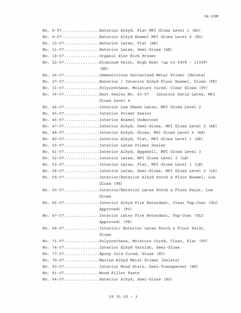
04-09M
09 91 00 - 3
No. 8-07................Exterior Alkyd, Flat MPI Gloss Level 1 (EO)
No. 9-07................Exterior Alkyd Enamel MPI Gloss Level 6 (EO)
No. 10-07...............Exterior Latex, Flat (AE)
No. 11-07...............Exterior Latex, Semi-Gloss (AE)
No. 18-07...............Organic Zinc Rich Primer
No. 22-07...............Aluminum Paint, High Heat (up to 590% - 1100F)
(HR)
No. 26-07...............Cementitious Galvanized Metal Primer [delete]
No. 27-07...............Exterior / Interior Alkyd Floor Enamel, Gloss (FE)
No. 31-07...............Polyurethane, Moisture Cured, Clear Gloss (PV)
No. 36-07...............Knot Sealer No. 43-07 Interior Satin Latex, MPI
Gloss Level 4
No. 44-07...............Interior Low Sheen Latex, MPI Gloss Level 2
No. 45-07...............Interior Primer Sealer
No. 46-07...............Interior Enamel Undercoat
No. 47-07...............Interior Alkyd, Semi-Gloss, MPI Gloss Level 5 (AK)
No. 48-07...............Interior Alkyd, Gloss, MPI Gloss Level 6 (AK)
No. 49-07...............Interior Alkyd, Flat, MPI Gloss Level 1 (AK)
No. 50-07...............Interior Latex Primer Sealer
No. 51-07...............Interior Alkyd, Eggshell, MPI Gloss Level 3
No. 52-07...............Interior Latex, MPI Gloss Level 3 (LE)
No. 53-07...............Interior Latex, Flat, MPI Gloss Level 1 (LE)
No. 54-07...............Interior Latex, Semi-Gloss, MPI Gloss Level 5 (LE)
No. 59-07...............Interior/Exterior Alkyd Porch & Floor Enamel, Low
Gloss (FE)
No. 60-07...............Interior/Exterior Latex Porch & Floor Paint, Low
Gloss
No. 66-07...............Interior Alkyd Fire Retardant, Clear Top-Coat (ULC
Approved) (FC)
No. 67-07...............Interior Latex Fire Retardant, Top-Coat (ULC
Approved) (FR)
No. 68-07...............Interior/ Exterior Latex Porch & Floor Paint,
Gloss
No. 71-07...............Polyurethane, Moisture Cured, Clear, Flat (PV)
No. 74-07...............Interior Alkyd Varnish, Semi-Gloss
No. 77-07...............Epoxy Cold Cured, Gloss (EC)
No. 79-07...............Marine Alkyd Metal Primer [Delete]
No. 90-07...............Interior Wood Stain, Semi-Transparent (WS)
No. 91-07...............Wood Filler Paste
No. 94-07...............Exterior Alkyd, Semi-Gloss (EO)
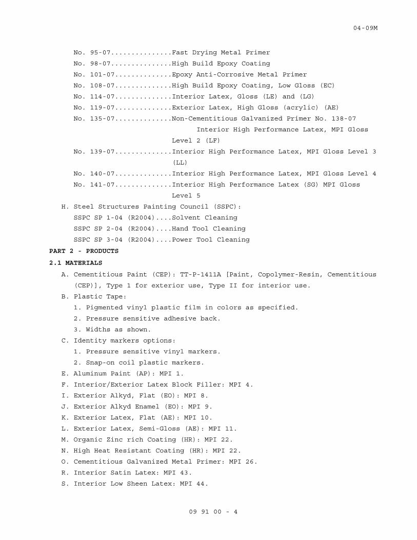
04-09M
09 91 00 - 4
No. 95-07...............Fast Drying Metal Primer
No. 98-07...............High Build Epoxy Coating
No. 101-07..............Epoxy Anti-Corrosive Metal Primer
No. 108-07..............High Build Epoxy Coating, Low Gloss (EC)
No. 114-07..............Interior Latex, Gloss (LE) and (LG)
No. 119-07..............Exterior Latex, High Gloss (acrylic) (AE)
No. 135-07..............Non-Cementitious Galvanized Primer No. 138-07
Interior High Performance Latex, MPI Gloss
Level 2 (LF)
No. 139-07..............Interior High Performance Latex, MPI Gloss Level 3
(LL)
No. 140-07..............Interior High Performance Latex, MPI Gloss Level 4
No. 141-07..............Interior High Performance Latex (SG) MPI Gloss
Level 5
H. Steel Structures Painting Council (SSPC):
SSPC SP 1-04 (R2004)....Solvent Cleaning
SSPC SP 2-04 (R2004)....Hand Tool Cleaning
SSPC SP 3-04 (R2004)....Power Tool Cleaning
PART 2 - PRODUCTS
2.1 MATERIALS
A. Cementitious Paint (CEP): TT-P-1411A [Paint, Copolymer-Resin, Cementitious
(CEP)], Type 1 for exterior use, Type II for interior use.
B. Plastic Tape:
1. Pigmented vinyl plastic film in colors as specified.
2. Pressure sensitive adhesive back.
3. Widths as shown.
C. Identity markers options:
1. Pressure sensitive vinyl markers.
2. Snap-on coil plastic markers.
E. Aluminum Paint (AP): MPI 1.
F. Interior/Exterior Latex Block Filler: MPI 4.
I. Exterior Alkyd, Flat (EO): MPI 8.
J. Exterior Alkyd Enamel (EO): MPI 9.
K. Exterior Latex, Flat (AE): MPI 10.
L. Exterior Latex, Semi-Gloss (AE): MPI 11.
M. Organic Zinc rich Coating (HR): MPI 22.
N. High Heat Resistant Coating (HR): MPI 22.
O. Cementitious Galvanized Metal Primer: MPI 26.
R. Interior Satin Latex: MPI 43.
S. Interior Low Sheen Latex: MPI 44.
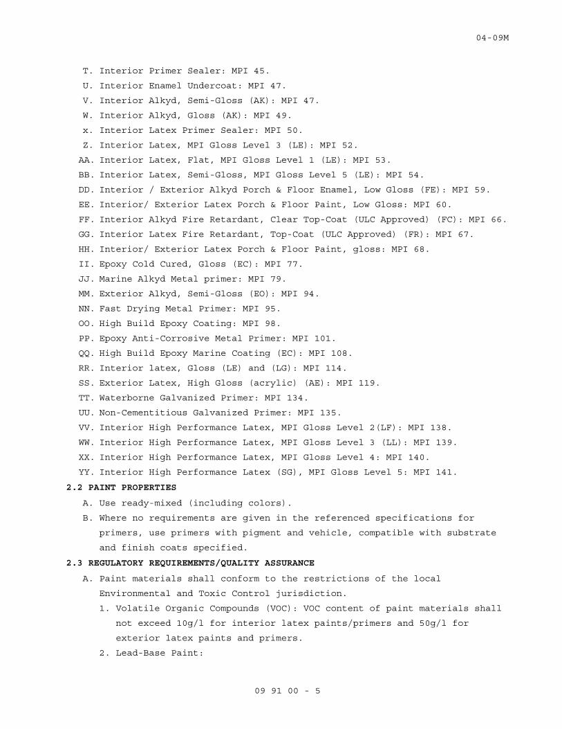
04-09M
09 91 00 - 5
T. Interior Primer Sealer: MPI 45.
U. Interior Enamel Undercoat: MPI 47.
V. Interior Alkyd, Semi-Gloss (AK): MPI 47.
W. Interior Alkyd, Gloss (AK): MPI 49.
x. Interior Latex Primer Sealer: MPI 50.
Z. Interior Latex, MPI Gloss Level 3 (LE): MPI 52.
AA. Interior Latex, Flat, MPI Gloss Level 1 (LE): MPI 53.
BB. Interior Latex, Semi-Gloss, MPI Gloss Level 5 (LE): MPI 54.
DD. Interior / Exterior Alkyd Porch & Floor Enamel, Low Gloss (FE): MPI 59.
EE. Interior/ Exterior Latex Porch & Floor Paint, Low Gloss: MPI 60.
FF. Interior Alkyd Fire Retardant, Clear Top-Coat (ULC Approved) (FC): MPI 66.
GG. Interior Latex Fire Retardant, Top-Coat (ULC Approved) (FR): MPI 67.
HH. Interior/ Exterior Latex Porch & Floor Paint, gloss: MPI 68.
II. Epoxy Cold Cured, Gloss (EC): MPI 77.
JJ. Marine Alkyd Metal primer: MPI 79.
MM. Exterior Alkyd, Semi-Gloss (EO): MPI 94.
NN. Fast Drying Metal Primer: MPI 95.
OO. High Build Epoxy Coating: MPI 98.
PP. Epoxy Anti-Corrosive Metal Primer: MPI 101.
QQ. High Build Epoxy Marine Coating (EC): MPI 108.
RR. Interior latex, Gloss (LE) and (LG): MPI 114.
SS. Exterior Latex, High Gloss (acrylic) (AE): MPI 119.
TT. Waterborne Galvanized Primer: MPI 134.
UU. Non-Cementitious Galvanized Primer: MPI 135.
VV. Interior High Performance Latex, MPI Gloss Level 2(LF): MPI 138.
WW. Interior High Performance Latex, MPI Gloss Level 3 (LL): MPI 139.
XX. Interior High Performance Latex, MPI Gloss Level 4: MPI 140.
YY. Interior High Performance Latex (SG), MPI Gloss Level 5: MPI 141.
2.2 PAINT PROPERTIES
A. Use ready-mixed (including colors).
B. Where no requirements are given in the referenced specifications for
primers, use primers with pigment and vehicle, compatible with substrate
and finish coats specified.
2.3 REGULATORY REQUIREMENTS/QUALITY ASSURANCE
A. Paint materials shall conform to the restrictions of the local
Environmental and Toxic Control jurisdiction.
1. Volatile Organic Compounds (VOC): VOC content of paint materials shall
not exceed 10g/l for interior latex paints/primers and 50g/l for
exterior latex paints and primers.
2. Lead-Base Paint:
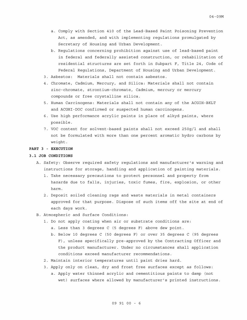
04-09M
09 91 00 - 6
a. Comply with Section 410 of the Lead-Based Paint Poisoning Prevention
Act, as amended, and with implementing regulations promulgated by
Secretary of Housing and Urban Development.
b. Regulations concerning prohibition against use of lead-based paint
in federal and federally assisted construction, or rehabilitation of
residential structures are set forth in Subpart F, Title 24, Code of
Federal Regulations, Department of Housing and Urban Development.
3. Asbestos: Materials shall not contain asbestos.
4. Chromate, Cadmium, Mercury, and Silica: Materials shall not contain
zinc-chromate, strontium-chromate, Cadmium, mercury or mercury
compounds or free crystalline silica.
5. Human Carcinogens: Materials shall not contain any of the ACGIH-BKLT
and ACGHI-DOC confirmed or suspected human carcinogens.
6. Use high performance acrylic paints in place of alkyd paints, where
possible.
7. VOC content for solvent-based paints shall not exceed 250g/l and shall
not be formulated with more than one percent aromatic hydro carbons by
weight.
PART 3 - EXECUTION
3.1 JOB CONDITIONS
A. Safety: Observe required safety regulations and manufacturer's warning and
instructions for storage, handling and application of painting materials.
1. Take necessary precautions to protect personnel and property from
hazards due to falls, injuries, toxic fumes, fire, explosion, or other
harm.
2. Deposit soiled cleaning rags and waste materials in metal containers
approved for that purpose. Dispose of such items off the site at end of
each days work.
B. Atmospheric and Surface Conditions:
1. Do not apply coating when air or substrate conditions are:
a. Less than 3 degrees C (5 degrees F) above dew point.
b. Below 10 degrees C (50 degrees F) or over 35 degrees C (95 degrees
F), unless specifically pre-approved by the Contracting Officer and
the product manufacturer. Under no circumstances shall application
conditions exceed manufacturer recommendations.
2. Maintain interior temperatures until paint dries hard.
3. Apply only on clean, dry and frost free surfaces except as follows:
a. Apply water thinned acrylic and cementitious paints to damp (not
wet) surfaces where allowed by manufacturer's printed instructions.

04-09M
09 91 00 - 7
b. Dampened with a fine mist of water on hot dry days concrete and
masonry surfaces to which water thinned acrylic and cementitious
paints are applied to prevent excessive suction and to cool surface.
3.2 SURFACE PREPARATION
A. Method of surface preparation is optional, provided results of finish
painting produce solid even color and texture specified with no overlays.
B. General:
1. Remove prefinished items not to be painted such as lighting fixtures,
escutcheon plates, hardware, trim, and similar items for reinstallation
after paint is dried.
2. Remove items for reinstallation and complete painting of such items and
adjacent areas when item or adjacent surface is not accessible or
finish is different.
3. See other sections of specifications for specified surface conditions
and prime coat.
4. Clean surfaces for painting with materials and methods compatible with
substrate and specified finish. Remove any residue remaining from
cleaning agents used. Do not use solvents, acid, or steam on concrete
and masonry.
C. Ferrous Metals:
1. Remove oil, grease, soil, drawing and cutting compounds, flux and other
detrimental foreign matter in accordance with SSPC-SP 1 (Solvent
Cleaning).
2. Remove loose mill scale, rust, and paint, by hand or power tool
cleaning, as defined in SSPC-SP 2 (Hand Tool Cleaning) and SSPC-SP 3
(Power Tool Cleaning). Exception: where high temperature aluminum paint
is used, prepare surface in accordance with paint manufacturer's
instructions.
3. Fill dents, holes and similar voids and depressions in flat exposed
surfaces of hollow steel doors and frames, access panels, roll-up steel
doors and similar items specified to have semi-gloss or gloss finish
with TT-F-322D (Filler, Two-Component Type, For Dents, Small Holes and
Blow-Holes). Finish flush with adjacent surfaces.
a. This includes flat head countersunk screws used for permanent
anchors.
b. Do not fill screws of item intended for removal such as glazing
beads.

04-09M
09 91 00 - 8
4. Spot prime abraded and damaged areas in shop prime coat which expose
bare metal with same type of paint used for prime coat. Feather edge of
spot prime to produce smooth finish coat.
5. Spot prime abraded and damaged areas which expose bare metal of factory
finished items with paint as recommended by manufacturer of item.
D. Zinc-Coated (Galvanized) Metal, Aluminum, Copper and Copper Alloys
Surfaces Specified Painted:
1. Clean surfaces to remove grease, oil and other deterrents to paint
adhesion in accordance with SSPC-SP 1 (Solvent Cleaning).
2. Spot coat abraded and damaged areas of zinc-coating which expose base
metal on hot-dip zinc-coated items with MPI 18 (Organic Zinc Rich
Coating). Prime or spot prime with MPI 134 (Waterborne Galvanized
Primer) or MPI 135 (Non- Cementitious Galvanized Primer) depending on
finish coat compatibility.
E. Masonry, Concrete, Cement Board and Cement Plaster
1. Clean and remove dust, dirt, oil, grease efflorescence, form release
agents, laitance, and other deterrents to paint adhesion.
2. Use emulsion type cleaning agents to remove oil, grease, paint and
similar products. Use of solvents, acid, or steam is not permitted.
3. Remove loose mortar in masonry work.
4. Replace mortar and fill open joints, holes, cracks and depressions with
new mortar. Do not fill weep holes. Finish to match adjacent surfaces.
5. Repair broken and spalled concrete edges with concrete patching
compound to match adjacent surfaces as specified in CONCRETE Sections.
Remove projections to level of adjacent surface by grinding or similar
methods.
F. Gypsum Plaster and Gypsum Board:
1. Remove efflorescence, loose and chalking plaster or finishing
materials.
2. Remove dust, dirt, and other deterrents to paint adhesion.
3. Fill holes, cracks, and other depressions with CID-A-A-1272A [Plaster,
Gypsum (Spackling Compound) finished flush with adjacent surface, with
texture to match texture of adjacent surface. Patch holes over 25 mm
(1-inch) in diameter as specified in Section for plaster or gypsum
board.
3.3 PAINT PREPARATION
A. Thoroughly mix painting materials to ensure uniformity of color, complete
dispersion of pigment and uniform composition.
04-09M
09 91 00 - 9
B. Do not thin unless necessary for application and when finish paint is used
for body and prime coats. Use materials and quantities for thinning as
specified in manufacturer's printed instructions.
C. Remove paint skins, then strain paint through commercial paint strainer to
remove lumps and other particles.
D. Mix two component and two part paint and those requiring additives in such
a manner as to uniformly blend as specified in manufacturer's printed
instructions unless specified otherwise.
E. For tinting required to produce exact shades specified, use color pigment
recommended by the paint manufacturer.
3.4 APPLICATION
A. Start of surface preparation or painting will be construed as acceptance
of the surface as satisfactory for the application of materials.
B. Unless otherwise specified, apply paint in three coats; prime, body, and
finish. When two coats applied to prime coat are the same, first coat
applied over primer is body coat and second coat is finish coat.
C. Apply each coat evenly and cover substrate completely.
D. Allow not less than 48 hours between application of succeeding coats,
except as allowed by manufacturer's printed instructions, and approved by
COR.
E. Finish surfaces to show solid even color, free from runs, lumps,
brushmarks, laps, holidays, or other defects.
F. Apply by brush, roller or spray, except as otherwise specified.
G. Do not spray paint in existing occupied spaces unless approved by COR,
except in spaces sealed from existing occupied spaces.
1. Apply painting materials specifically required by manufacturer to be
applied by spraying.
2. In areas, where paint is applied by spray, mask or enclose with
polyethylene, or similar air tight material with edges and seams
continuously sealed including items specified in WORK NOT PAINTED,
motors, controls, telephone, and electrical equipment, fronts of
sterilizes and other recessed equipment and similar prefinished items.
3.5 PRIME PAINTING
A. After surface preparation prime surfaces before application of body and
finish coats, except as otherwise specified.
B. Spot prime and apply body coat to damaged and abraded painted surfaces
before applying succeeding coats.
C. Additional field applied prime coats over shop or factory applied prime
coats are not required except for exterior exposed steel apply an
additional prime coat.
04-09M
09 91 00 - 10
D. Prime rebates for stop and face glazing of wood, and for face glazing of
steel.
E. Metals except boilers, incinerator stacks, and engine exhaust pipes:
1. Steel and iron: MPI 79 (Marine Alkyd Metal Primer). Use MPI 101 (Cold
Curing Epoxy Primer) where MPI 77 (Epoxy Cold Cured, Gloss (EC)) finish
is specified.
2. Zinc-coated steel and iron: MPI 134 (Waterborne Galvanized Primer) .
3. Aluminum scheduled to be painted: MPI 95 (Fast Drying Metal Primer).
4. Copper and copper alloys scheduled to be painted: MPI 95 (Fast Drying
Metal Primer).
5. Machinery not factory finished: MPI 9 (Exterior Alkyd Enamel (EO)).
3.7 INTERIOR FINISHES
A. Metal Work:
1. Apply to exposed surfaces.
2. Omit body and finish coats on surfaces concealed after installation
except electrical conduit containing conductors over 600 volts.
3. Ferrous Metal, Galvanized Metal, and Other Metals Scheduled:
a. Apply two coats of MPI 47 (Interior Alkyd, Semi-Gloss (AK)) unless
specified otherwise.
b. Two coats of MPI 48 (Interior Alkyd Gloss (AK)) .
c. One coat of MPI 46 (Interior Enamel Undercoat) plus one coat of MPI
47 (Interior Alkyd, Semi-Gloss (AK)) on exposed interior surfaces of
alkyd-amine enamel prime finished windows.
d. Machinery: One coat MPI 9 (Exterior Alkyd Enamel (EO)).
3.8 REFINISHING EXISTING PAINTED SURFACES
A. Clean, patch and repair existing surfaces as specified under surface
preparation.
B. Remove and reinstall items as specified under surface preparation.
C. Remove existing finishes or apply separation coats to prevent non
compatible coatings from having contact.
D. Patched or Replaced Areas in Surfaces and Components: Apply spot prime and
body coats as specified for new work to repaired areas or replaced
components.
E. Except where scheduled for complete painting apply finish coat over plane
surface to nearest break in plane, such as corner, reveal, or frame.
F. Refinish areas as specified for new work to match adjoining work unless
specified or scheduled otherwise.
G. Sand or dull glossy surfaces prior to painting.
04-09M
09 91 00 - 11
H. Sand existing coatings to a feather edge so that transition between new
and existing finish will not show in finished work.
3.9 PAINT COLOR
A. For additional requirements regarding color see Articles, REFINISHING
EXISTING PAINTED SURFACE and MECHANICAL AND ELECTRICAL FIELD PAINTING
SCHEDULE.
B. Coat Colors:
1. Color of priming coat: Lighter than body coat.
2. Color of body coat: Lighter than finish coat.
3. Color prime and body coats to not show through the finish coat and to
mask surface imperfections or contrasts.
3.10 MECHANICAL AND ELECTRICAL WORK FIELD PAINTING SCHEDULE
A. Field painting of mechanical and electrical consists of cleaning,
touching-up abraded shop prime coats, and applying prime, body and finish
coats to materials and equipment if not factory finished in space
scheduled to be finished.
B. Paint various systems specified in Division 23 – HEATING, VENTILATION AND
AIR-CONDITIONING, Division 26 - ELECTRICAL, Division 27 - COMMUNICATIONS.
C. Paint after tests have been completed.
D. Omit prime coat from factory prime-coated items.
E. Finish painting of mechanical and electrical equipment is not required
when located in interstitial spaces, above suspended ceilings, in
concealed areas such as pipe and electric closets, pipe basements, pipe
tunnels, trenches, attics, roof spaces, shafts and furred spaces except on
electrical conduit containing feeders 600 volts or more.
F. Omit field painting of items specified in paragraph, Building and
Structural WORK NOT PAINTED.
G. Color:
1. Paint items having no color specified in to match surrounding surfaces.
2. Paint colors as specified for following:
a. Federal Safety Red: Exposed fire protection piping hydrants, post
indicators, electrical conducts containing fire alarm control
wiring, and fire alarm equipment.
H. Apply paint systems on properly prepared and primed surface as follows:
1. Interior Locations:
a. Apply two coats of MPI 47 (Interior Alkyd, Semi-Gloss (AK)) to
following items:
1) Metal under 94 degrees C (200 degrees F) of items such as bare
piping, fittings, hangers and supports.
04-09M
09 91 00 - 12
2) Equipment and systems such as hinged covers and frames for
control cabinets and boxes, cast-iron radiators, electric
conduits and panel boards.
3) Heating, ventilating, air conditioning, plumbing equipment, and
machinery having shop prime coat and not factory finished.
3.11 IDENTITY PAINTING SCHEDULE
A. Identify designated service in accordance with ANSI A13.1, unless
specified otherwise, on exposed piping, piping above removable ceilings,
piping in accessible pipe spaces, interstitial spaces, and piping behind
access panels.
1. Legend may be identified using 2.1 G options or by stencil
applications.
2. Apply legends adjacent to changes in direction, on branches, where
pipes pass through walls or floors, adjacent to operating accessories
such as valves, regulators, strainers and cleanouts a minimum of 12 000
mm (40 feet) apart on straight runs of piping. Identification next to
plumbing fixtures is not required.
3. Locate Legends clearly visible from operating position.
4. Use arrow to indicate direction of flow.
5. Identify pipe contents with sufficient additional details such as
temperature, pressure, and contents to identify possible hazard. Insert
working pressure shown on drawings where asterisk appears for High,
Medium, and Low Pressure designations as follows:
a. High Pressure - 414 kPa (60 psig) and above.
b. Medium Pressure - 104 to 413 kPa (15 to 59 psig).
c. Low Pressure - 103 kPa (14 psig) and below.
6. Legend name in full or in abbreviated form as follows:
COLOR OF COLOR OF LEGEND
PIPING BACKGROUND LETTERS BBREVIATIONS
Chilled Water Supply Green White Ch. Wtr Sup
Chilled Water Return Green White Ch. Wtr Ret
High Pressure Steam Yellow Black H.P. ______*
High Pressure Condensate Return Yellow Black H.P. Ret ____*
Medium Pressure Steam Yellow Black M. P. Stm ____*
Medium Pressure Condensate Return Yellow Black M.P. Ret _____*
Low Pressure Steam Yellow Black L.P. Stm _____*
Low Pressure Condensate Return Yellow Black L.P. Ret _____*
Hot Water Heating Supply Yellow Black H. W. Htg Sup
Hot Water Heating Return Yellow Black H. W. Htg Ret
04-09M
09 91 00 - 13
B. Fire and Smoke Partitions:
1. Identify partitions above ceilings on both sides of partitions except
within shafts in letters not less than 64 mm (2 1/2 inches) high.
2. Stenciled message: "SMOKE BARRIER" or, "FIRE BARRIER" as applicable.
3. Locate not more than 6100 mm (20 feet) on center on corridor sides of
partitions, and with a least one message per room on room side of
partition.
4. Use semigloss paint of color that contrasts with color of substrate.
C. Identify columns in pipe basements and interstitial space:
1. Apply stenciled number and letters to correspond with grid numbering
and lettering shown.
2. Paint numbers and letters 100 mm (4 inches) high, locate 450 mm (18
inches) below overhead structural slab.
3. Apply on four sides of interior columns and on inside face only of
exterior wall columns.
4. Color:
a. Use black on concrete columns.
b. Use white or contrasting color on steel columns.
3.12 PROTECTION CLEAN UP, AND TOUCH-UP
A. Protect work from paint droppings and spattering by use of masking, drop
cloths, removal of items or by other approved methods.
B. Upon completion, clean paint from hardware, glass and other surfaces and
items not required to be painted of paint drops or smears.
C. Before final inspection, touch-up or refinished in a manner to produce
solid even color and finish texture, free from defects in work which was
damaged or discolored.
- - - E N D - - -
11-10
23 05 11 - 1
SECTION 23 05 11 COMMON WORK RESULTS FOR HVAC
PART 1 - GENERAL
1.1 DESCRIPTION
A. The requirements of this Section apply to all sections of Division 23.
B. Definitions:
1. Exposed: Piping, ductwork, and equipment exposed to view in finished
rooms.
2. Option or optional: Contractor's choice of an alternate material or
method.
3. COR: Contracting Officer’s Technical Representative.
1.2 RELATED WORK
A. Section GENERAL CONDITIONS B. Section 01 00 00, GENERAL REQUIREMENTS C. Section 01 33 23, SHOP DRAWINGS, PRODUCT DATA, and SAMPLES D. Section 07 84 00, FIRESTOPPING
E. Section 07 92 00, JOINT SEALANTS
F. Section 09 91 00, PAINTING
G. Section 23 05 93, TESTING, ADJUSTING, and BALANCING FOR HVAC
H. Section 23 07 11, HVAC, PLUMBING, and Boiler Plant Insulation
I. Section 23 09 23, DIRECT-DIGITAL CONTROL SYSTEM FOR HVAC
J. Section 23 21 13, HYDRONIC PIPING
K. Section 23 22 13, STEAM and CONDENSATE HEATING PIPINGL.
L. Section 26 05 11, REQUIREMENTS FOR ELECTRICAL INSTALLATIONS
1.3 QUALITY ASSURANCE
A. Mechanical, electrical and associated systems shall be safe, reliable,
efficient, durable, easily and safely operable and maintainable, easily
and safely accessible, and in compliance with applicable codes as
specified. The systems shall be comprised of high quality institutional-
class and industrial-class products of manufacturers that are
experienced specialists in the required product lines. All construction
firms and personnel shall be experienced and qualified specialists in
industrial and institutional HVAC
B. Flow Rate Tolerance for HVAC Equipment: Section 23 05 93, TESTING,
ADJUSTING, AND BALANCING FOR HVAC.
C. Products Criteria:
1. Standard Products: Material and equipment shall be the standard
products of a manufacturer regularly engaged in the manufacture of
11-10
23 05 11 - 2
the products for at least 3 years (or longer as specified elsewhere).
The design, model and size of each item shall have been in
satisfactory and efficient operation on at least three installations
for approximately three years. However, digital electronics devices,
software and systems such as controls, instruments, computer work
station, shall be the current generation of technology and basic
design that has a proven satisfactory service record of at least
three years. See other specification sections for any exceptions
and/or additional requirements.
2. All items furnished shall be free from defects that would adversely
affect the performance, maintainability and appearance of individual
components and overall assembly.
3. Conform to codes and standards as required by the specifications.
Conform to local codes, if required by local authorities such as the
natural gas supplier, if the local codes are more stringent then
those specified. Refer any conflicts to the COR.
4. Multiple Units: When two or more units of materials or equipment of
the same type or class are required, these units shall be products of
one manufacturer.
5. Assembled Units: Manufacturers of equipment assemblies, which use
components made by others, assume complete responsibility for the
final assembled product.
6. Nameplates: Nameplate bearing manufacturer's name or identifiable
trademark shall be securely affixed in a conspicuous place on
equipment, or name or trademark cast integrally with equipment,
stamped or otherwise permanently marked on each item of equipment.
7. Asbestos products or equipment or materials containing asbestos shall
not be used.
D. Equipment Service Organizations:
1. HVAC: Products and systems shall be supported by service
organizations that maintain a complete inventory of repair parts and
are located within 50 miles to the site.
E. HVAC Mechanical Systems Welding: Before any welding is performed,
contractor shall submit a certificate certifying that welders comply
with the following requirements:
1. Qualify welding processes and operators for piping according to ASME
"Boiler and Pressure Vessel Code", Section IX, "Welding and Brazing
Qualifications".
2. Comply with provisions of ASME B31 series "Code for Pressure Piping".
11-10
23 05 11 - 3
3. Certify that each welder has passed American Welding Society (AWS)
qualification tests for the welding processes involved, and that
certification is current.
F. Execution (Installation, Construction) Quality:
1. Apply and install all items in accordance with manufacturer's written
instructions. Refer conflicts between the manufacturer's instructions
and the contract drawings and specifications to the COR for
resolution. Provide written hard copies or computer files of
manufacturer’s installation instructions to the COR at least two
weeks prior to commencing installation of any item. Installation of
the item will not be allowed to proceed until the recommendations are
received. Failure to furnish these recommendations is a cause for
rejection of the material.
2. Provide complete layout drawings required by Paragraph, SUBMITTALS.
Do not commence construction work on any system until the layout
drawings have been approved.
G. Upon request by Government, provide lists of previous installations for
selected items of equipment. Include contact persons who will serve as
references, with telephone numbers and e-mail addresses.
1.4 SUBMITTALS
A. Submit in accordance with Section 01 33 23, SHOP DRAWINGS, PRODUCT DATA,
AND SAMPLES, and with requirements in the individual specification
sections.
B. Contractor shall make all necessary field measurements and
investigations to assure that the equipment and assemblies will meet
contract requirements.
C. If equipment is submitted which differs in arrangement from that shown,
provide drawings that show the rearrangement of all associated systems.
Approval will be given only if all features of the equipment and
associated systems, including accessibility, are equivalent to that
required by the contract.
D. Prior to submitting shop drawings for approval, contractor shall certify
in writing that manufacturers of all major items of equipment have each
reviewed drawings and specifications, and have jointly coordinated and
properly integrated their equipment and controls to provide a complete
and efficient installation.
E. Submittals and shop drawings for interdependent items, containing
applicable descriptive information, shall be furnished together and
complete in a group. Coordinate and properly integrate materials and
11-10
23 05 11 - 4
equipment in each group to provide a completely compatible and
efficient.
F. Layout Drawings:
1. Submit complete consolidated and coordinated layout drawings for all
new systems, and for existing systems that are in the same areas.
Refer to Section GENERAL CONDITIONS, Article, SUBCONTRACTS AND WORK
COORDINATION.
2. The drawings shall include plan views, elevations and sections of all
systems and shall be on a scale of not less than 1:32 (3/8-inch equal
to one foot). Clearly identify and dimension the proposed locations
of the principal items of equipment. The drawings shall clearly show
locations and adequate clearance for all equipment, piping, valves,
control panels and other items. Show the access means for all items
requiring access for operations and maintenance. Provide detailed
layout drawings of all piping and duct systems.
3. Do not install equipment foundations, equipment or piping until
layout drawings have been approved.
4. In addition, for HVAC systems provide details of the following:
a. Hangers, inserts, supports, and bracing.
b. Pipe sleeves.
c. Duct or equipment penetrations of floors, walls, ceilings, or
roofs.
G. Manufacturer's Literature and Data: Submit under the pertinent section
rather than under this section.
1. Equipment and materials identification.
2. Fire-stopping materials.
3. Hangers, inserts, supports and bracing. Provide load calculations for
variable spring and constant support hangers.
4. Wall, floor, and ceiling plates.
H. HVAC Maintenance Data and Operating Instructions:
1. Maintenance and operating manuals in accordance with Section 01 00
00, GENERAL REQUIREMENTS, Article, INSTRUCTIONS, for systems and
equipment.
2. Provide a listing of recommended replacement parts for keeping in
stock supply, including sources of supply, for equipment. Include in
the listing belts for equipment: Belt manufacturer, model number,
size and style, and distinguished whether of multiple belt sets.
I. Provide copies of approved HVAC equipment submittals to the Testing,
Adjusting and Balancing Subcontractor.
11-10
23 05 11 - 5
1.5 APPLICABLE PUBLICATIONS
A. The publications listed below form a part of this specification to the
extent referenced. The publications are referenced in the text by the
basic designation only.
B. Air Conditioning, Heating and Refrigeration Institute (AHRI):
430-2009................Central Station Air-Handling Units
C. American National Standard Institute (ANSI):
B31.1-2007..............Power Piping
D. Rubber Manufacturers Association (ANSI/RMA):
IP-20-2007..............Specifications for Drives Using Classical
V-Belts and Sheaves
IP-21-2009..............Specifications for Drives Using Double-V
(Hexagonal) Belts
IP-22-2007..............Specifications for Drives Using Narrow V-Belts
and Sheaves
E. Air Movement and Control Association (AMCA):
410-96..................Recommended Safety Practices for Air Moving
Devices
F. American Society of Mechanical Engineers (ASME):
Boiler and Pressure Vessel Code (BPVC):
Section I-2007..........Power Boilers
Section IX-2007.........Welding and Brazing Qualifications
Code for Pressure Piping:
B31.1-2007..............Power Piping
G. American Society for Testing and Materials (ASTM):
A36/A36M-08.............Standard Specification for Carbon Structural
Steel
A575-96(2007)...........Standard Specification for Steel Bars, Carbon,
Merchant Quality, M-Grades
E84-10..................Standard Test Method for Surface Burning
Characteristics of Building Materials
E119-09c................Standard Test Methods for Fire Tests of Building
Construction and Materials
H. Manufacturers Standardization Society (MSS) of the Valve and Fittings
Industry, Inc:
SP-58-2009..............Pipe Hangers and Supports-Materials, Design and
Manufacture, Selection, Application, and
Installation
SP 69-2003..............Pipe Hangers and Supports-Selection and
Application

11-10
23 05 11 - 6
SP 127-2001.............Bracing for Piping Systems, Seismic – Wind –
Dynamic, Design, Selection, Application
I. National Electrical Manufacturers Association (NEMA): MG-1-2009...............Motors and Generators
J. National Fire Protection Association (NFPA):
31-06...................Standard for Installation of Oil-Burning
Equipment
54-09...................National Fuel Gas Code
70-08...................National Electrical Code
85-07...................Boiler and Combustion Systems Hazards Code
90A-09..................Standard for the Installation of Air
Conditioning and Ventilating Systems
101-09..................Life Safety Code
1.6 DELIVERY, STORAGE AND HANDLING
A. Protection of Equipment:
1. Equipment and material placed on the job site shall remain in the
custody of the Contractor until phased acceptance, whether or not the
Government has reimbursed the Contractor for the equipment and
material. The Contractor is solely responsible for the protection of
such equipment and material against any damage.
2. Place damaged equipment in first class, new operating condition; or,
replace same as determined and directed by the COR. Such repair or
replacement shall be at no additional cost to the Government.
3. Protect interiors of new equipment and piping systems against entry
of foreign matter. Clean both inside and outside before painting or
placing equipment in operation.
4. Existing equipment and piping being worked on by the Contractor shall
be under the custody and responsibility of the Contractor and shall
be protected as required for new work.
B. Cleanliness of Piping and Equipment Systems:
1. Exercise care in storage and handling of equipment and piping
material to be incorporated in the work. Remove debris arising from
cutting, threading and welding of piping.
2. Piping systems shall be flushed, blown or pigged as necessary to
deliver clean systems.
3. Contractor shall be fully responsible for all costs, damage, and
delay arising from failure to provide clean systems.
11-10
23 05 11 - 7
1.7 JOB CONDITIONS – WORK IN EXISTING BUILDING
A. Building Operation: Government employees will be continuously operating
and managing all facilities, including temporary facilities, that serve
the medical center.
B. Maintenance of Service: Schedule all work to permit continuous service
as required by the medical center.
C. Steam and Condensate Service Interruptions: Limited steam and condensate
service interruptions, as required for interconnections of new and
existing systems, will be permitted by the COR during periods when the
demands are not critical to the operation of the medical center. These
non-critical periods are limited to between 8 pm and 5 am in the
appropriate off-season (if applicable). Provide at least one week
advance notice to the COR.
D. Phasing of Work: Comply with all requirements shown on drawings or
specified.
E. Building Working Environment: Maintain the architectural and structural
integrity of the building and the working environment at all times.
Maintain the interior of building at 18 degrees C (65 degrees F)
minimum. Limit the opening of doors, windows or other access openings to
brief periods as necessary for rigging purposes. No storm water or
ground water leakage permitted. Provide daily clean-up of construction
and demolition debris on all floor surfaces and on all equipment being
operated by VA.
F. Acceptance of Work for Government Operation: As new facilities are made
available for operation and these facilities are of beneficial use to
the Government, inspections will be made and tests will be performed.
Based on the inspections, a list of contract deficiencies will be issued
to the Contractor. After correction of deficiencies as necessary for
beneficial use, the Contracting Officer will process necessary
acceptance and the equipment will then be under the control and
operation of Government personnel.
PART 2 - PRODUCTS
2.1 FACTORY-ASSEMBLED PRODUCTS
A. Provide maximum standardization of components to reduce spare part
requirements.
B. Manufacturers of equipment assemblies that include components made by
others shall assume complete responsibility for final assembled unit.
1. All components of an assembled unit need not be products of same
manufacturer.
11-10
23 05 11 - 8
2. Constituent parts that are alike shall be products of a single
manufacturer.
3. Components shall be compatible with each other and with the total
assembly for intended service.
4. Contractor shall guarantee performance of assemblies of components,
and shall repair or replace elements of the assemblies as required to
deliver specified performance of the complete assembly.
C. Components of equipment shall bear manufacturer's name and trademark,
model number, serial number and performance data on a name plate
securely affixed in a conspicuous place, or cast integral with, stamped
or otherwise permanently marked upon the components of the equipment.
D. Major items of equipment, which serve the same function, must be the
same make and model. Exceptions will be permitted if performance
requirements cannot be met.
2.2 COMPATIBILITY OF RELATED EQUIPMENT
A. Equipment and materials installed shall be compatible in all respects
with other items being furnished and with existing items so that the
result will be a complete and fully operational plant that conforms to
contract requirements.
2.3 EQUIPMENT AND MATERIALS IDENTIFICATION
A. Use symbols, nomenclature and equipment numbers specified, shown on the
drawings and shown in the maintenance manuals. Identification for piping
is specified in Section 09 91 00, PAINTING. B. Interior (Indoor)
Equipment: Engraved nameplates, with letters not less than 48 mm
(3/16-inch) high of brass with black-filled letters, or rigid black
plastic with white letters specified in Section 09 91 00, PAINTING
permanently fastened to the equipment. Identify unit components such as
coils, filters, fans, etc.
B. Exterior (Outdoor) Equipment: Brass nameplates, with engraved black
filled letters, not less than 48 mm (3/16-inch) high riveted or bolted
to the equipment. D. Control Items: Label all temperature and
humidity sensors, controllers and control dampers. Identify and label
each item as they appear on the control diagrams.
C. Valve Tags and Lists:
1. HVAC and Boiler Plant: Provide for all valves other than for
equipment in Section 23 82 00, CONVECTION HEATING AND COOLING UNITS.
2. Valve tags: Engraved black filled numbers and letters not less than
13 mm (1/2-inch) high for number designation, and not less than 6.4
mm(1/4-inch) for service designation on 19 gage 38 mm (1-1/2 inches)
round brass disc, attached with brass "S" hook or brass chain.
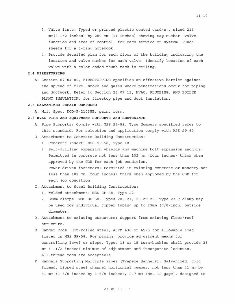
11-10
23 05 11 - 9
3. Valve lists: Typed or printed plastic coated card(s), sized 216
mm(8-1/2 inches) by 280 mm (11 inches) showing tag number, valve
function and area of control, for each service or system. Punch
sheets for a 3-ring notebook.
4. Provide detailed plan for each floor of the building indicating the
location and valve number for each valve. Identify location of each
valve with a color coded thumb tack in ceiling.
2.4 FIRESTOPPING
A. Section 07 84 00, FIRESTOPPING specifies an effective barrier against
the spread of fire, smoke and gases where penetrations occur for piping
and ductwork. Refer to Section 23 07 11, HVAC, PLUMBING, AND BOILER
PLANT INSULATION, for firestop pipe and duct insulation.
2.5 GALVANIZED REPAIR COMPOUND
A. Mil. Spec. DOD-P-21035B, paint form.
2.6 HVAC PIPE AND EQUIPMENT SUPPORTS AND RESTRAINTS
A. Pipe Supports: Comply with MSS SP-58. Type Numbers specified refer to
this standard. For selection and application comply with MSS SP-69.
B. Attachment to Concrete Building Construction:
1. Concrete insert: MSS SP-58, Type 18.
2. Self-drilling expansion shields and machine bolt expansion anchors:
Permitted in concrete not less than 102 mm (four inches) thick when
approved by the COR for each job condition.
3. Power-driven fasteners: Permitted in existing concrete or masonry not
less than 102 mm (four inches) thick when approved by the COR for
each job condition.
C. Attachment to Steel Building Construction:
1. Welded attachment: MSS SP-58, Type 22.
2. Beam clamps: MSS SP-58, Types 20, 21, 28 or 29. Type 23 C-clamp may
be used for individual copper tubing up to 23mm (7/8-inch) outside
diameter.
D. Attachment to existing structure: Support from existing floor/roof
structure.
E. Hanger Rods: Hot-rolled steel, ASTM A36 or A575 for allowable load
listed in MSS SP-58. For piping, provide adjustment means for
controlling level or slope. Types 13 or 15 turn-buckles shall provide 38
mm (1-1/2 inches) minimum of adjustment and incorporate locknuts.
All-thread rods are acceptable.
F. Hangers Supporting Multiple Pipes (Trapeze Hangers): Galvanized, cold
formed, lipped steel channel horizontal member, not less than 41 mm by
41 mm (1-5/8 inches by 1-5/8 inches), 2.7 mm (No. 12 gage), designed to
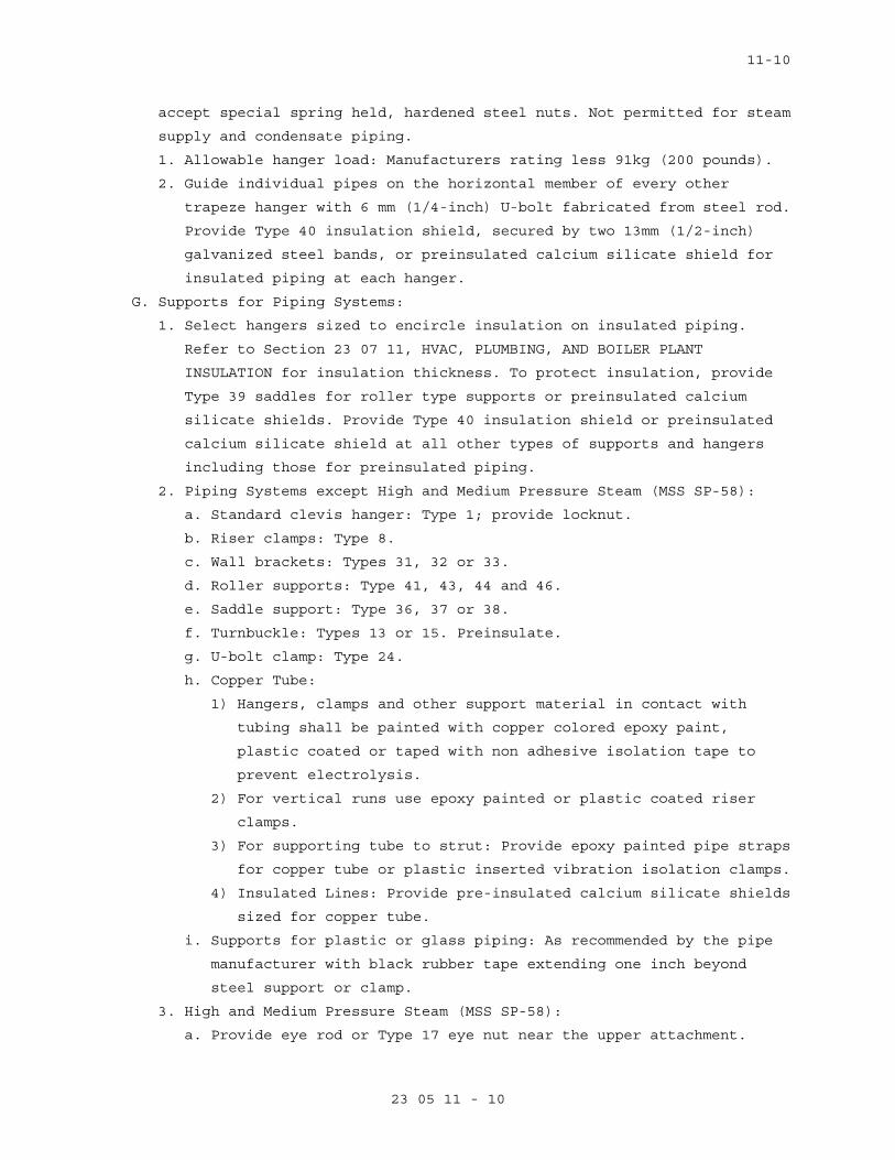
11-10
23 05 11 - 10
accept special spring held, hardened steel nuts. Not permitted for steam
supply and condensate piping.
1. Allowable hanger load: Manufacturers rating less 91kg (200 pounds).
2. Guide individual pipes on the horizontal member of every other
trapeze hanger with 6 mm (1/4-inch) U-bolt fabricated from steel rod.
Provide Type 40 insulation shield, secured by two 13mm (1/2-inch)
galvanized steel bands, or preinsulated calcium silicate shield for
insulated piping at each hanger.
G. Supports for Piping Systems:
1. Select hangers sized to encircle insulation on insulated piping.
Refer to Section 23 07 11, HVAC, PLUMBING, AND BOILER PLANT
INSULATION for insulation thickness. To protect insulation, provide
Type 39 saddles for roller type supports or preinsulated calcium
silicate shields. Provide Type 40 insulation shield or preinsulated
calcium silicate shield at all other types of supports and hangers
including those for preinsulated piping.
2. Piping Systems except High and Medium Pressure Steam (MSS SP-58):
a. Standard clevis hanger: Type 1; provide locknut.
b. Riser clamps: Type 8.
c. Wall brackets: Types 31, 32 or 33.
d. Roller supports: Type 41, 43, 44 and 46.
e. Saddle support: Type 36, 37 or 38.
f. Turnbuckle: Types 13 or 15. Preinsulate.
g. U-bolt clamp: Type 24.
h. Copper Tube:
1) Hangers, clamps and other support material in contact with
tubing shall be painted with copper colored epoxy paint,
plastic coated or taped with non adhesive isolation tape to
prevent electrolysis.
2) For vertical runs use epoxy painted or plastic coated riser
clamps.
3) For supporting tube to strut: Provide epoxy painted pipe straps
for copper tube or plastic inserted vibration isolation clamps.
4) Insulated Lines: Provide pre-insulated calcium silicate shields
sized for copper tube.
i. Supports for plastic or glass piping: As recommended by the pipe
manufacturer with black rubber tape extending one inch beyond
steel support or clamp.
3. High and Medium Pressure Steam (MSS SP-58):
a. Provide eye rod or Type 17 eye nut near the upper attachment.
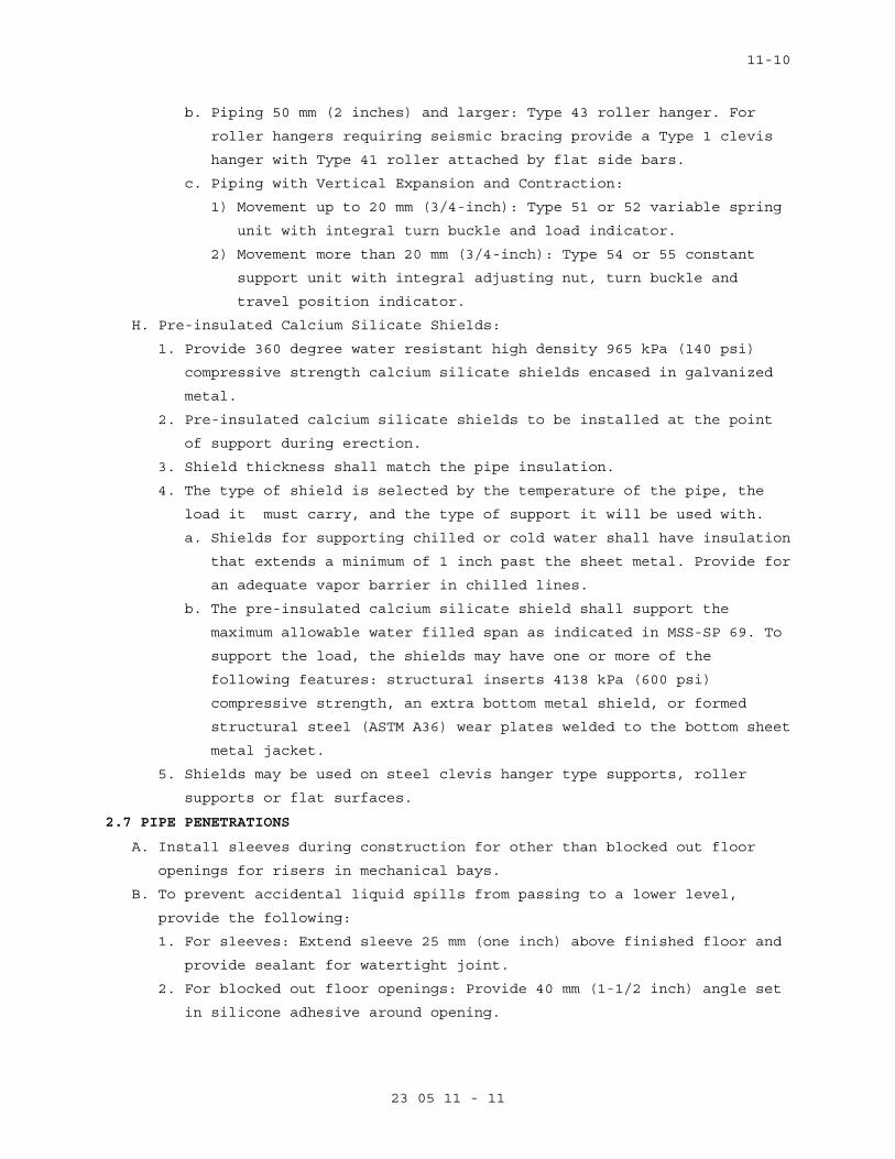
11-10
23 05 11 - 11
b. Piping 50 mm (2 inches) and larger: Type 43 roller hanger. For
roller hangers requiring seismic bracing provide a Type 1 clevis
hanger with Type 41 roller attached by flat side bars.
c. Piping with Vertical Expansion and Contraction:
1) Movement up to 20 mm (3/4-inch): Type 51 or 52 variable spring
unit with integral turn buckle and load indicator.
2) Movement more than 20 mm (3/4-inch): Type 54 or 55 constant
support unit with integral adjusting nut, turn buckle and
travel position indicator.
H. Pre-insulated Calcium Silicate Shields:
1. Provide 360 degree water resistant high density 965 kPa (140 psi)
compressive strength calcium silicate shields encased in galvanized
metal.
2. Pre-insulated calcium silicate shields to be installed at the point
of support during erection.
3. Shield thickness shall match the pipe insulation.
4. The type of shield is selected by the temperature of the pipe, the
load it must carry, and the type of support it will be used with.
a. Shields for supporting chilled or cold water shall have insulation
that extends a minimum of 1 inch past the sheet metal. Provide for
an adequate vapor barrier in chilled lines.
b. The pre-insulated calcium silicate shield shall support the
maximum allowable water filled span as indicated in MSS-SP 69. To
support the load, the shields may have one or more of the
following features: structural inserts 4138 kPa (600 psi)
compressive strength, an extra bottom metal shield, or formed
structural steel (ASTM A36) wear plates welded to the bottom sheet
metal jacket.
5. Shields may be used on steel clevis hanger type supports, roller supports or flat surfaces.
2.7 PIPE PENETRATIONS
A. Install sleeves during construction for other than blocked out floor
openings for risers in mechanical bays.
B. To prevent accidental liquid spills from passing to a lower level,
provide the following:
1. For sleeves: Extend sleeve 25 mm (one inch) above finished floor and
provide sealant for watertight joint.
2. For blocked out floor openings: Provide 40 mm (1-1/2 inch) angle set
in silicone adhesive around opening.
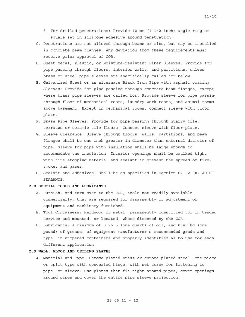
11-10
23 05 11 - 12
3. For drilled penetrations: Provide 40 mm (1-1/2 inch) angle ring or
square set in silicone adhesive around penetration.
C. Penetrations are not allowed through beams or ribs, but may be installed
in concrete beam flanges. Any deviation from these requirements must
receive prior approval of COR.
D. Sheet Metal, Plastic, or Moisture-resistant Fiber Sleeves: Provide for
pipe passing through floors, interior walls, and partitions, unless
brass or steel pipe sleeves are specifically called for below.
E. Galvanized Steel or an alternate Black Iron Pipe with asphalt coating
Sleeves: Provide for pipe passing through concrete beam flanges, except
where brass pipe sleeves are called for. Provide sleeve for pipe passing
through floor of mechanical rooms, laundry work rooms, and animal rooms
above basement. Except in mechanical rooms, connect sleeve with floor
plate.
F. Brass Pipe Sleeves: Provide for pipe passing through quarry tile,
terrazzo or ceramic tile floors. Connect sleeve with floor plate.
G. Sleeve Clearance: Sleeve through floors, walls, partitions, and beam
flanges shall be one inch greater in diameter than external diameter of
pipe. Sleeve for pipe with insulation shall be large enough to
accommodate the insulation. Interior openings shall be caulked tight
with fire stopping material and sealant to prevent the spread of fire,
smoke, and gases.
H. Sealant and Adhesives: Shall be as specified in Section 07 92 00, JOINT
SEALANTS.
2.8 SPECIAL TOOLS AND LUBRICANTS
A. Furnish, and turn over to the COR, tools not readily available
commercially, that are required for disassembly or adjustment of
equipment and machinery furnished.
B. Tool Containers: Hardwood or metal, permanently identified for in tended
service and mounted, or located, where directed by the COR.
C. Lubricants: A minimum of 0.95 L (one quart) of oil, and 0.45 kg (one
pound) of grease, of equipment manufacturer's recommended grade and
type, in unopened containers and properly identified as to use for each
different application.
2.9 WALL, FLOOR AND CEILING PLATES
A. Material and Type: Chrome plated brass or chrome plated steel, one piece
or split type with concealed hinge, with set screw for fastening to
pipe, or sleeve. Use plates that fit tight around pipes, cover openings
around pipes and cover the entire pipe sleeve projection.
11-10
23 05 11 - 13
B. Thickness: Not less than 2.4 mm (3/32-inch) for floor plates. For wall
and ceiling plates, not less than 0.64 mm (0.025-inch) for up to 80 mm
(3-inch pipe), 0.89 mm (0.035-inch) for larger pipe.
C. Locations: Use where pipe penetrates floors, walls and ceilings in
exposed locations, in finished areas only. Provide a watertight joint in
spaces where brass or steel pipe sleeves are specified.
2.10 ASBESTOS
Materials containing asbestos are not permitted.
PART 3 - EXECUTION
3.1 ARRANGEMENT AND INSTALLATION OF EQUIPMENT AND PIPING
A. Coordinate location of piping, sleeves, inserts, hangers, ductwork and
equipment. Locate piping, sleeves, inserts, hangers, ductwork and
equipment clear of windows, doors, openings, light outlets, and other
services and utilities. Prepare equipment layout drawings to coordinate
proper location and personnel access of all facilities. Submit the
drawings for review as required by Part 1. Follow manufacturer's
published recommendations for installation methods not otherwise
specified.
B. Operating Personnel Access and Observation Provisions: Select and
arrange all equipment and systems to provide clear view and easy access,
without use of portable ladders, for maintenance and operation of all
devices including, but not limited to: all equipment items, valves,
filters, strainers, transmitters, sensors, control devices. All gages
and indicators shall be clearly visible by personnel standing on the
floor or on permanent platforms. Do not reduce or change maintenance and
operating space and access provisions that are shown on the drawings.
C. Equipment and Piping Support: Coordinate structural systems necessary
for pipe and equipment support with pipe and equipment locations to
permit proper installation.
D. Location of pipe sleeves, trenches and chases shall be accurately
coordinated with equipment and piping locations.
E. Cutting Holes:
1. Cut holes through concrete and masonry by rotary core drill.
Pneumatic hammer, impact electric, and hand or manual hammer type
drill will not be allowed, except as permitted by COR where working
area space is limited.
2. Locate holes to avoid interference with structural members such as
beams or grade beams. Holes shall be laid out in advance and drilling
done only after approval by COR. If the Contractor considers it
11-10
23 05 11 - 14
necessary to drill through structural members, this matter shall be
referred to COR for approval.
3. Do not penetrate membrane waterproofing.
F. Interconnection of Instrumentation or Control Devices: Generally,
electrical and pneumatic interconnections are not shown but must be
provided.
G. Minor Piping: Generally, small diameter pipe runs from drips and drains,
water cooling, and other service are not shown but must be provided.
H. Electrical and Pneumatic Interconnection of Controls and Instruments:
This generally not shown but must be provided. This includes
interconnections of sensors, transmitters, transducers, control devices,
control and instrumentation panels, instruments and computer
workstations. Comply with NFPA-70.
I. Protection and Cleaning:
1. Equipment and materials shall be carefully handled, properly stored,
and adequately protected to prevent damage before and during
installation, in accordance with the manufacturer's recommendations
and as approved by the COR. Damaged or defective items in the opinion
of the COR, shall be replaced.
2. Protect all finished parts of equipment, such as shafts and bearings
where accessible, from rust prior to operation by means of protective
grease coating and wrapping. Close pipe openings with caps or plugs
during installation. Tightly cover and protect fixtures and equipment
against dirt, water chemical, or mechanical injury. At completion of
all work thoroughly clean fixtures, exposed materials and equipment.
J. Concrete and Grout: Use concrete and shrink compensating grout 25 MPa
(3000 psi) minimum.
K. Install gages, thermometers, valves and other devices with due regard
for ease in reading or operating and maintaining said devices. Locate
and position thermometers and gages to be easily read by operator or
staff standing on floor or walkway provided. Servicing shall not require
dismantling adjacent equipment or pipe work.
L. Work in Existing Building:
1. Perform as specified in Article, OPERATIONS AND STORAGE AREAS,
Article, ALTERATIONS, and Article, RESTORATION of the Section 01 00
00, GENERAL REQUIREMENTS for relocation of existing equipment,
alterations and restoration of existing building(s).
2. As specified in Section 01 00 00, GENERAL REQUIREMENTS, Article,
OPERATIONS AND STORAGE AREAS, make alterations to existing service
11-10
23 05 11 - 15
piping at times that will least interfere with normal operation of
the facility.
3. Cut required openings through existing masonry and reinforced
concrete using diamond core drills. Use of pneumatic hammer type
drills, impact type electric drills, and hand or manual hammer type
drills, will be permitted only with approval of the COR. Locate
openings that will least effect structural slabs, columns, ribs or
beams. Refer to the COR for determination of proper design for
openings through structural sections and opening layouts approval,
prior to cutting or drilling into structure. After COR's approval,
carefully cut opening through construction no larger than absolutely
necessary for the required installation.
M. Switchgear/Electrical Equipment Drip Protection: Every effort shall be
made to eliminate the installation of pipe above electrical and
telephone switchgear. If this is not possible, encase pipe in a second
pipe with a minimum of joints. Installation of piping, ductwork, leak
protection apparatus or other installations foreign to the electrical
installation shall be located in the space equal to the width and depth
of the equipment and extending from to a height of 1.8 m (6 ft.) above
the equipment of to ceiling structure, whichever is lower (NFPA 70).
N. Inaccessible Equipment:
1. Where the Government determines that the Contractor has installed
equipment not conveniently accessible for operation and maintenance,
equipment shall be removed and reinstalled or remedial action
performed as directed at no additional cost to the Government.
2. The term "conveniently accessible" is defined as capable of being
reached without the use of ladders, or without climbing or crawling
under or over obstacles such as motors, fans, pumps, belt guards,
transformers, high voltage lines, piping, and ductwork.
3.2 TEMPORARY PIPING AND EQUIPMENT
A. Continuity of operation of existing facilities will generally require
temporary installation or relocation of equipment and piping.
B. The Contractor shall provide all required facilities in accordance with
the requirements of phased construction and maintenance of service. All
piping and equipment shall be properly supported, sloped to drain,
operate without excessive stress, and shall be insulated where injury
can occur to personnel by contact with operating facilities. The
requirements of Paragraph 3.1 apply.
11-10
23 05 11 - 16
C. Temporary facilities and piping shall be completely removed and any
openings in structures sealed. Provide necessary blind flanges and caps
to seal open piping remaining in service.
3.3 PIPE AND EQUIPMENT SUPPORTS
A. Where hanger spacing does not correspond with joist or rib spacing, use
structural steel channels secured directly to joist and rib structure
that will correspond to the required hanger spacing, and then suspend
the equipment and piping from the channels. Drill or burn holes in
structural steel only with the prior approval of the COR.
B. Use of chain, wire or strap hangers; wood for blocking, stays and
bracing; or, hangers suspended from piping above will not be permitted.
Replace or thoroughly clean rusty products and paint with zinc primer.
C. Use hanger rods that are straight and vertical. Turnbuckles for vertical
adjustments may be omitted where limited space prevents use. Provide a
minimum of 15 mm (1/2-inch) clearance between pipe or piping covering
and adjacent work.
D. HVAC Horizontal Pipe Support Spacing: Refer to MSS SP-69. Provide
additional supports at valves, strainers, in-line pumps and other heavy
components. Provide a support within one foot of each elbow.
E. HVAC Vertical Pipe Supports:
1. Up to 150 mm (6-inch pipe), 9 m (30 feet) long, bolt riser clamps to
the pipe below couplings, or welded to the pipe and rests supports
securely on the building structure.
2. Vertical pipe larger than the foregoing, support on base elbows or
tees, or substantial pipe legs extending to the building structure.
F. Overhead Supports:
1. The basic structural system of the building is designed to sustain
the loads imposed by equipment and piping to be supported overhead.
2. Provide steel structural members, in addition to those shown, of
adequate capability to support the imposed loads, located in
accordance with the final approved layout of equipment and piping.
3. Tubing and capillary systems shall be supported in channel troughs.
3.4 MECHANICAL DEMOLITION
A. Rigging access, other than indicated on the drawings, shall be provided
by the Contractor after approval for structural integrity by the COR.
Such access shall be provided without additional cost or time to the
Government. Where work is in an operating plant, provide approved
protection from dust and debris at all times for the safety of plant
personnel and maintenance of plant operation and environment of the
plant.
11-10
23 05 11 - 17
B. In an operating facility, maintain the operation, cleanliness and
safety. Government personnel will be carrying on their normal duties of
operating, cleaning and maintaining equipment and plant operation.
Confine the work to the immediate area concerned; maintain cleanliness
and wet down demolished materials to eliminate dust. Do not permit
debris to accumulate in the area to the detriment of plant operation.
Perform all flame cutting to maintain the fire safety integrity of this
plant. Adequate fire extinguishing facilities shall be available at all
times. Perform all work in accordance with recognized fire protection
standards. Inspection will be made by personnel of the VA Medical
Center, and Contractor shall follow all directives of the PE or COR with
regard to rigging, safety, fire safety, and maintenance of operations.
C. Completely remove all piping, wiring, conduit, and other devices
associated with the equipment not to be re-used in the new work. This
includes all pipe, valves, fittings, insulation, and all hangers
including the top connection and any fastenings to building structural
systems. Seal all openings, after removal of equipment, pipes, ducts,
and other penetrations in roof, walls, floors, in an approved manner and
in accordance with plans and specifications where specifically covered.
Structural integrity of the building system shall be maintained.
Reference shall also be made to the drawings and specifications of the
other disciplines in the project for additional facilities to be
demolished or handled.
D. All valves including gate, globe, ball, butterfly and check, all
pressure gages and thermometers with wells shall remain Government
property and shall be removed and delivered to COR and stored as
directed. The Contractor shall remove all other material and equipment,
devices and demolition debris under these plans and specifications. Such
material shall be removed from Government property expeditiously and
shall not be allowed to accumulate.
3.5 CLEANING AND PAINTING
A. Prior to final inspection and acceptance of the plant and facilities for
beneficial use by the Government, the plant facilities, equipment and
systems shall be thoroughly cleaned and painted. Refer to Section 09 91
00, PAINTING.
B. In addition, the following special conditions apply:
1. Cleaning shall be thorough. Use solvents, cleaning materials and methods recommended by the manufacturers for the specific tasks.
Remove all rust prior to painting and from surfaces to remain
11-10
23 05 11 - 18
unpainted. Repair scratches, scuffs, and abrasions prior to applying
prime and finish coats.
2. Material And Equipment Not To Be Painted Includes: a. Motors, controllers, control switches, and safety switches.
b. Control and interlock devices.
c. Regulators.
d. Pressure reducing valves.
e. Control valves and thermostatic elements.
f. Lubrication devices and grease fittings.
g. Copper, brass, aluminum, stainless steel and bronze surfaces.
h. Valve stems and rotating shafts.
i. Pressure gauges and thermometers.
j. Glass.
k. Name plates.
3. Control and instrument panels shall be cleaned, damaged surfaces
repaired, and shall be touched-up with matching paint obtained from
panel manufacturer.
4. Pumps, motors, steel and cast iron bases, and coupling guards shall
be cleaned, and shall be touched-up with the same color as utilized
by the pump manufacturer
5. Paint shall withstand temperatures without peeling or discoloration.
a. Steam -- 52 degrees C (125 degrees F) on insulation jacket surface
and 190 degrees C (375 degrees F) on metal pipe surface.
6. Final result shall be smooth, even-colored, even-textured factory
finish on all items. Completely repaint the entire piece of
equipment if necessary to achieve this.
3.6 IDENTIFICATION SIGNS
A. Provide laminated plastic signs, with engraved lettering not less than
5 mm (3/16-inch) high, designating functions, for all equipment,
switches, motor controllers, relays, meters, control devices, including
automatic control valves. Nomenclature and identification symbols shall
correspond to that used in maintenance manual, and in diagrams specified
elsewhere. Attach by chain, adhesive, or screws.
B. Factory Built Equipment: Metal plate, securely attached, with name and
address of manufacturer, serial number, model number, size, performance.
C. Pipe Identification: Refer to Section 09 91 00, PAINTING.
3.7 LUBRICATION
A. Lubricate all devices requiring lubrication prior to initial operation.
Field-check all devices for proper lubrication.
11-10
23 05 11 - 19
B. Equip all devices with required lubrication fittings or devices. Provide
a minimum of one liter (one quart) of oil and 0.5 kg (one pound) of
grease of manufacturer's recommended grade and type for each different
application; also provide 12 grease sticks for lubricated plug valves.
Deliver all materials to COR in unopened containers that are properly
identified as to application.
C. Provide a separate grease gun with attachments for applicable fittings
for each type of grease applied.
D. All lubrication points shall be accessible without disassembling
equipment, except to remove access plates.
3.8 STARTUP AND TEMPORARY OPERATION
Start up equipment as described in equipment specifications. Verify that
vibration is within specified tolerance prior to extended operation.
Temporary use of equipment is specified in Section 01 00 00, GENERAL
REQUIREMENTS, Article, TEMPORARY USE OF MECHANICAL AND ELECTRICAL
EQUIPMENT.
3.9 OPERATING AND PERFORMANCE TESTS
A. Prior to the final inspection, perform required tests as specified in
Section 01 00 00, GENERAL REQUIREMENTS and submit the test reports and
records to the COR.
B. Should evidence of malfunction in any tested system, or piece of
equipment or component part thereof, occur during or as a result of
tests, make proper corrections, repairs or replacements, and repeat
tests at no additional cost to the Government.
C. When completion of certain work or system occurs at a time when final
control settings and adjustments cannot be properly made to make
performance tests, then make performance tests for heating systems and
for cooling systems respectively during first actual seasonal use of
respective systems following completion of work.
3.10 INSTRUCTIONS TO VA PERSONNEL
Provide in accordance with Article, INSTRUCTIONS, of Section 01 00 00,
GENERAL REQUIREMENTS.
- - - E N D - - -
05-11
23 05 93 - 1
SECTION 23 05 93 TESTING, ADJUSTING, AND BALANCING FOR HVAC
PART 1 - GENERAL
1.1 DESCRIPTION
A. Testing, adjusting, and balancing (TAB) of heating, ventilating and air
conditioning (HVAC) systems. TAB includes the following:
1. Planning systematic TAB procedures.
2. Pre-construction Readings Report.
3. Final balancing air and water systems; adjustment of total system to
provide pre-construction performance; and testing performance of
equipment and automatic controls.
4. Recording and reporting results.
B. Definitions:
1. Basic TAB used in this Section: Chapter 37, "Testing, Adjusting and
Balancing" of 2007 ASHRAE Handbook, "HVAC Applications".
2. TAB: Testing, Adjusting and Balancing; the process of checking and
adjusting HVAC systems to meet design objectives.
3. AABC: Associated Air Balance Council.
4. NEBB: National Environmental Balancing Bureau.
5. Hydronic Systems: Includes chilled water, heating hot water.
6. Air Systems: Includes all outside air, supply air, return air,
exhaust air and relief air systems.
7. Flow rate tolerance: The allowable percentage variation, minus to
plus, of actual flow rate from values (design) in the contract
documents.
1.2 RELATED WORK
A. Section 23 05 11, COMMON WORK RESULTS FOR HVAC: General Mechanical
Requirements.
B. Section 23 07 11, HVAC INSULATION: Piping and Equipment Insulation.
C. Section 23 09 23, DIRECT-DIGITAL CONTROL SYSTEM FOR HVAC: Controls and
Instrumentation Settings.
D. Section 23 21 13, HYDRONIC PIPING
1.3 QUALITY ASSURANCE
A. Refer to Articles, Quality Assurance and Submittals, in Section
23 05 11, COMMON WORK RESULTS FOR HVAC.
B. Qualifications:
05-11
23 05 93 - 2
1. TAB Agency: The TAB agency shall be a subcontractor of the General
Contractor and shall report to and be paid by the General
Contractor.
2. The TAB agency shall be either a certified member of AABC or
certified by the NEBB to perform TAB service for HVAC, water
balancing and vibrations and sound testing of equipment. The
certification shall be maintained for the entire duration of duties
specified herein. If, for any reason, the agency loses subject
certification during this period, the General Contractor shall
immediately notify the COR and submit another TAB firm for approval.
Any agency that has been the subject of disciplinary action by
either the AABC or the NEBB within the five years preceding Contract
Award shall not be eligible to perform any work related to the TAB.
All work performed in this Section and in other related Sections by
the TAB agency shall be considered invalid if the TAB agency loses
its certification prior to Contract completion, and the successor
agency’s review shows unsatisfactory work performed by the
predecessor agency.
3. TAB Specialist: The TAB specialist shall be either a member of AABC
or an experienced technician of the Agency certified by NEBB. The
certification shall be maintained for the entire duration of duties
specified herein. If, for any reason, the Specialist loses subject
certification during this period, the General Contractor shall
immediately notify the COR and submit another TAB Specialist for
approval. Any individual that has been the subject of disciplinary
action by either the AABC or the NEBB within the five years
preceding Contract Award shall not be eligible to perform any duties
related to the HVAC systems, including TAB. All work specified in
this Section and in other related Sections performed by the TAB
specialist shall be considered invalid if the TAB Specialist loses
its certification prior to Contract completion and must be performed
by an approved successor.
4. TAB Specialist shall be identified by the General Contractor within
60 days after the notice to proceed. The TAB specialist will be
coordinating, scheduling and reporting all TAB work and related
activities and will provide necessary information as required by the
COR. The responsibilities would specifically include:
a. Shall directly supervise all TAB work.
05-11
23 05 93 - 3
b. Shall sign the TAB reports that bear the seal of the TAB
standard. The reports shall be accompanied by report forms and
schematic drawings required by the TAB standard, AABC or NEBB.
c. Would follow all TAB work through its satisfactory completion.
d. Shall provide final markings of settings of all HVAC adjustment
devices.
e. Permanently mark location of duct test ports.
5. All TAB technicians performing actual TAB work shall be experienced
and must have done satisfactory work on a minimum of 3 projects
comparable in size and complexity to this project. Qualifications
must be certified by the TAB agency in writing. The lead technician
shall be certified by AABC or NEBB
C. Test Equipment Criteria: The instrumentation shall meet the
accuracy/calibration requirements established by AABC National
Standards or by NEBB Procedural Standards for Testing, Adjusting and
Balancing of Environmental Systems and instrument manufacturer. Provide
calibration history of the instruments to be used for test and balance
purpose.
D. Tab Criteria:
1. One or more of the applicable AABC, NEBB or SMACNA publications,
supplemented by ASHRAE Handbook "HVAC Applications" Chapter 36, and
requirements stated herein shall be the basis for planning,
procedures, and reports.
2. Flow rate tolerance: Following tolerances are allowed. For
tolerances not mentioned herein follow ASHRAE Handbook "HVAC
Applications", Chapter 36, as a guideline. Air Filter resistance
during tests, artificially imposed if necessary, shall be at least
100 percent of manufacturer recommended change over pressure drop
values for pre-filters and after-filters.
a. Air handling unit and all other fans, cubic meters/min (cubic
feet per minute): Minus 0 percent to plus l0 percent.
b. Minimum outside air: 0 percent to plus 10 percent.
c. Heating hot water coils: Minus 5 percent to plus 5 percent.
d. Chilled water pumps: Minus 0 percent to plus 5 percent.
e. Chilled water coils: Minus 0 percent to plus 5 percent.
3. Systems shall be adjusted for energy efficient operation as
described in PART 3.
05-11
23 05 93 - 4
4. Typical TAB procedures and results shall be demonstrated to the COR
for one air distribution system (including all fans, three terminal
units, three rooms randomly selected by the COR) and one hydronic
system (pumps and three coils) as follows:
a. When field TAB work begins.
b. During each partial final inspection and the final inspection for
the project if requested by VA.
1.4 SUBMITTALS
A. Submit in accordance with Section 01 33 23, SHOP DRAWINGS, PRODUCT
DATA, and SAMPLES.
B. Submit names and qualifications of TAB agency and TAB specialists
within 60 days after the notice to proceed. Submit information on three
recently completed projects and a list of proposed test equipment.
C. For use by the COR staff, submit one complete set of applicable AABC or
NEBB publications that will be the basis of TAB work.
D. Submit Following for Review and Approval:
1. Pre-construction Readings Report within 30 days for conventional
design projects. .
2. Intermediate and Final TAB reports covering flow balance and
adjustments, performance tests.
3. Include in final reports uncorrected installation deficiencies noted
during TAB and applicable explanatory comments on test results that
differ from design requirements.
E. Prior to request for Final or Partial Final inspection, submit
completed Test and Balance report for the area.
1.5 APPLICABLE PUBLICATIONS
A. The following publications form a part of this specification to the
extent indicated by the reference thereto. In text the publications are
referenced to by the acronym of the organization.
B. American Society of Heating, Refrigerating and Air Conditioning
Engineers, Inc. (ASHRAE):
2007 ...................HVAC Applications ASHRAE Handbook, Chapter 37,
Testing, Adjusting, and Balancing and Chapter
47, Sound and Vibration Control
C. Associated Air Balance Council (AABC):
2002....................AABC National Standards for Total System
Balance

05-11
23 05 93 - 5
D. National Environmental Balancing Bureau (NEBB):
7th Edition 2005 ........Procedural Standards for Testing, Adjusting,
Balancing of Environmental Systems
2nd Edition 2006 .......Procedural Standards for the Measurement of
Sound and Vibration
3rd Edition 2009 ........Procedural Standards for Whole Building Systems
Commissioning of New Construction
E. Sheet Metal and Air Conditioning Contractors National Association
(SMACNA):
3rd Edition 2002 ........HVAC SYSTEMS Testing, Adjusting and Balancing
PART 2 - PRODUCTS
2.1 PLUGS
A. Provide plastic plugs to seal holes drilled in ductwork for test
purposes.
2.2 INSULATION REPAIR MATERIAL
A. See Section 23 07 11, HVAC INSULATION Provide for repair of insulation
removed or damaged for TAB work.
PART 3 - EXECUTION
3.1 GENERAL
A. Refer to TAB Criteria in Article, Quality Assurance.
B. Obtain applicable contract documents and copies of approved submittals
for HVAC equipment and automatic control systems.
3.2 PRECONSTRUCTION READINGS REPORT
A. The TAB Specialist shall take pre-construction water and air flows at
all affected equipment and review the Contract Plans and specifications
and advise the COR of any design deficiencies that would prevent the
HVAC systems from effectively operating in accordance with the sequence
of operation specified or prevent the effective and accurate TAB of the
system. The TAB Specialist shall provide a report individually listing
each deficiency and the corresponding proposed corrective action
necessary for proper system operation.
B. The TAB Specialist shall be responsible to document all existing
conditions associated with the equipment and components to be addressed
as a part of this project, with the intent of reinstating operation
equal to that at the start of the project. Form example is provided as
attachment 230593.1.
05-11
23 05 93 - 6
3.3 SYSTEM READINESS REPORT
A. The TAB Contractor shall measure existing air and water flow rates
associated with existing systems utilized to serve renovated areas as
indicated on drawings. Submit report of findings to COR.
B. Inspect each System to ensure that it is complete including
installation and operation of controls. Submit report to RE in
standard format and forms prepared and or approved by the A/E.
C. Verify that all items such as ductwork piping, ports, terminals,
connectors, etc., that is required for TAB are installed. Provide a
report to the COR.
3.4 TAB REPORTS
A. Submit an intermediate report for 50 percent of systems and equipment
tested and balanced to establish satisfactory test results.
B. The TAB contractor shall provide raw data immediately in writing to the
COR if there is a problem in achieving intended results before
submitting a formal report.
C. If over 20 percent of readings in the intermediate report fall outside
the acceptable range, the TAB report shall be considered invalid and
all contract TAB work shall be repeated and re-submitted for approval
at no additional cost to the owner.
D. Do not proceed with the remaining systems until intermediate report is
approved by the COR.
E. TAB contractor shall provide means of confirming that original
conditions at the start of the project have been restored.
3.5 TAB PROCEDURES
A. Tab shall be performed in accordance with the requirement of the
Standard under which TAB agency is certified by either AABC or NEBB.
B. General: During TAB all related system components shall be in full
operation. Fan and pump rotation, motor loads and equipment vibration
shall be checked and corrected as necessary before proceeding with TAB.
Set controls and/or block off parts of distribution systems to simulate
design operation of variable volume air or water systems for test and
balance work.
C. Coordinate TAB procedures with existing systems and any phased
construction completion requirements for the project. Provide TAB
reports for pre construction air and water flow rate and for each phase
of the project prior to partial final inspections of each phase of the

05-11
23 05 93 - 7
project. Return existing areas outside the work area to pre
constructed conditions.
D. Allow 15 days time in construction schedule for TAB and submission of
all reports for an organized and timely correction of deficiencies.
E. Air Balance and Equipment Test: Include air handling units, fans.
1. Artificially load air filters by partial blanking to produce air
pressure drop of manufacturer’s recommended pressure drop.
2. Adjust fan speeds to provide design air flow.
3. Test and balance systems in all specified modes of operation,
including variable volume, economizer, and fire emergency modes.
Verify that dampers and other controls function properly.
4. Variable air volume (VAV) systems:
a. Coordinate TAB, including system volumetric controls, with
Section 23 09 23, DIRECT-DIGITAL CONTROL SYSTEM FOR HVAC.
5. Record final measurements for existing air handling equipment
performance data sheets.
F. Water Balance and Equipment Test: Include existing circulating pumps,
coils:
1. Adjust flow rates for equipment. Set coils to preconstruction
values, if different from values on contract drawings.
2. Primary-secondary (variable volume) systems: Coordinate TAB with
Section 23 09 23, DIRECT-DIGITAL CONTROL SYSTEM FOR HVAC. Balance
systems at design water flow and then verify that variable flow
controls function as designed.3. Record final measurements for
hydronic equipment on performance data sheets. Include entering and
leaving water temperatures for heating and cooling coils. Include
entering and leaving air temperatures (DB/WB for cooling coils) for
air handling units and reheat coils. Make air and water temperature
measurements at the same time.
3.6 MARKING OF SETTINGS
A. Following approval of Tab final Report, the setting of all HVAC
adjustment devices including valves, splitters and dampers shall be
permanently marked by the TAB Specialist so that adjustment can be
restored if disturbed at any time. Style and colors used for markings
shall be coordinated with the COR.
3.7 IDENTIFICATION OF TEST PORTS
A. The TAB Specialist shall permanently and legibly identify the location
points of duct test ports. If the ductwork has exterior insulation, the
05-11
23 05 93 - 8
identification shall be made on the exterior side of the insulation.
All penetrations through ductwork and ductwork insulation shall be
sealed to prevent air leaks and maintain integrity of vapor barrier.
3.8 PHASING
A. Phased Projects: Testing and Balancing Work to follow project with
areas shall be completed per the project phasing. Upon completion of
the project all areas shall have been tested and balanced per the
contract documents.
B. Existing Areas: Systems that serve areas outside of the project scope
shall not be adversely affected. Measure existing parameters where
shown to document system capacity.
- - E N D - - -
05-11
23 07 11 - 1
SECTION 23 07 11 HVAC AND BOILER PLANT INSULATION
PART 1 - GENERAL
1.1 DESCRIPTION
A. Field applied insulation for thermal efficiency and condensation
control for HVAC piping, ductwork, and equipment.
B. Definitions
1. ASJ: All service jacket, white finish facing or jacket.
2. Air conditioned space: Space having air temperature and/or humidity
controlled by mechanical equipment.
3. Cold: Equipment, ductwork or piping handling media at design
temperature of 16 degrees C (60 degrees F) or below.
4. Concealed: Ductwork and piping above ceilings and in chases, and
pipe spaces.
5. Exposed: Piping, ductwork, and equipment exposed to view in finished
areas including mechanical and electrical equipment rooms. Shafts,
chases, and pipe basements are not considered finished areas.
6. FSK: Foil-scrim-kraft facing.
7. Hot: HVAC Ductwork handling air at design temperature above 16
degrees C (60 degrees F);HVAC equipment or piping handling media
above 41 degrees C (105 degrees F).
8. Density: kg/m3 - kilograms per cubic meter (Pcf - pounds per cubic
foot).
9. Runouts: Branch pipe connections up to 25-mm (one-inch) nominal size
to fan coil units or reheat coils for terminal units.
10. Thermal conductance: Heat flow rate through materials.
a. Flat surface: Watt per square meter (BTU per hour per square
foot).
b. Pipe or Cylinder: Watt per square meter (BTU per hour per linear
foot).
11. Thermal Conductivity (k): Watt per meter, per degree C (BTU per inch
thickness, per hour, per square foot, per degree F temperature
difference).
12. Vapor Retarder (Vapor Barrier): A material which retards the
transmission (migration) of water vapor. Performance of the vapor
retarder is rated in terms of permeance (perms). For the purpose of
this specification, vapor retarders shall have a maximum published
05-11
23 07 11 - 2
permeance of 0.1 perms and vapor barriers shall have a maximum
published permeance of 0.001 perms.
13. MPS: Medium pressure steam (110 kPa [16 psig] thru 414 kPa [59
psig].
14. MPR: Medium pressure steam condensate return.
15. LPS: Low pressure steam (103 kPa [15 psig] and below).
16. LPR: Low pressure steam condensate gravity return.17. HWH: Hot
water heating supply.
17. HWHR: Hot water heating return.
18. CH: Chilled water supply.
19. CHR: Chilled water return.
20. PVDC: Polyvinylidene chloride vapor retarder jacketing, white.
1.2 RELATED WORK
A. Section 07 84 00, FIRESTOPPING: Mineral fiber and bond breaker behind
sealant.
B. Section 23 05 11, COMMON WORK RESULTS FOR HVAC: General mechanical
requirements and items, which are common to more than one section of
Division 23.
C. Section 23 22 13, STEAM and CONDENSATE HEATING PIPING
D. Section 23 21 13, HYDRONIC PIPING: Piping and equipment.
E. Section 23 21 13, HYDRONIC PIPING: Hot water, chilled water piping.
1.3 QUALITY ASSURANCE
A. Refer to article QUALITY ASSURANCE, in Section 23 05 11, COMMON WORK
RESULTS FOR HVAC.
B. Criteria:
1. Comply with NFPA 90A, particularly paragraphs 4.3.3.1 through
4.3.3.6, 4.3.10.2.6, and 5.4.6.4, parts of which are quoted as
follows:
4.3.3.1 Pipe insulation and coverings, duct coverings, duct linings, vapor retarder facings, adhesives, fasteners, tapes, and supplementary materials added to air ducts, plenums, panels, and duct silencers used in duct systems, unless otherwise provided for in 4.3.3.1.1 or 4.3.3.1.2., shall have, in the form in which they are used, a maximum flame spread index of 25 without evidence of continued progressive combustion and a maximum smoke developed index of 50 when tested in accordance with NFPA 255, Standard Method of Test of Surface Burning Characteristics of Building Materials.
4.3.3.1.1 Where these products are to be applied with adhesives, they shall be tested with such adhesives applied, or the adhesives used shall have a maximum flame spread index of 25 and
05-11
23 07 11 - 3
a maximum smoke developed index of 50 when in the final dry state. (See 4.2.4.2.)
4.3.3.1.2 The flame spread and smoke developed index requirements of 4.3.3.1.1 shall not apply to air duct weatherproof coverings where they are located entirely outside of a building, do not penetrate a wall or roof, and do not create an exposure hazard.
4.3.3.2 Closure systems for use with rigid and flexible air ducts tested in accordance with UL 181, Standard for Safety Factory-Made Air Ducts and Air Connectors, shall have been tested, listed, and used in accordance with the conditions of their listings, in accordance with one of the following:
(1) UL 181A, Standard for Safety Closure Systems for Use with Rigid Air Ducts and Air Connectors
(2) UL 181B, Standard for Safety Closure Systems for Use with Flexible Air Ducts and Air Connectors
4.3.3.3 Air duct, panel, and plenum coverings and linings, and pipe insulation and coverings shall not flame, glow, smolder, or smoke when tested in accordance with a similar test for pipe covering, ASTM C 411, Standard Test Method for Hot-Surface Performance of High-Temperature Thermal Insulation, at the temperature to which they are exposed in service.
4.3.3.3.1 In no case shall the test temperature be below 121°C (250°F).
4.3.3.4 Air duct coverings shall not extend through walls or floors that are required to be fire stopped or required to have a fire resistance rating, unless such coverings meet the requirements of 5.4.6.4.
4.3.3.5* Air duct linings shall be interrupted at fire dampers to prevent interference with the operation of devices.
4.3.3.6 Air duct coverings shall not be installed so as to conceal or prevent the use of any service opening.
4.3.10.2.6 Materials exposed to the airflow shall be noncombustible or limited combustible and have a maximum smoke developed index of 50 or comply with the following.
4.3.10.2.6.1 Electrical wires and cables and optical fiber cables shall be listed as noncombustible or limited combustible and have a maximum smoke developed index of 50 or shall be listed as having a maximum peak optical density of 0.5 or less, an average optical density of 0.15 or less, and a maximum flame spread distance of 1.5 m (5 ft) or less when tested in accordance with NFPA 262, Standard Method of Test for Flame Travel and Smoke of Wires and Cables for Use in Air-Handling Spaces.
4.3.10.2.6.4 Optical-fiber and communication raceways shall be listed as having a maximum peak optical density of 0.5 or less, an average optical density of 0.15 or less, and a maximum flame spread distance of 1.5 m (5 ft) or less when tested in accordance with UL 2024, Standard for Safety Optical-Fiber Cable Raceway.
4.3.10.2.6.6 Supplementary materials for air distribution systems shall be permitted when complying with the provisions of 4.3.3.
05-11
23 07 11 - 4
5.4.6.4 Where air ducts pass through walls, floors, or partitions that are required to have a fire resistance rating and where fire dampers are not required, the opening in the construction around the air duct shall be as follows:
(1) Not exceeding a 25.4 mm (1 in.) average clearance on all sides
(2) Filled solid with an approved material capable of preventing the passage of flame and hot gases sufficient to ignite cotton waste when subjected to the time-temperature fire conditions required for fire barrier penetration as specified in NFPA 251, Standard Methods of Tests of Fire Endurance of Building Construction and Materials
2. Test methods: ASTM E84, UL 723, or NFPA 255.
3. Specified k factors are at 24 degrees C (75 degrees F) mean
temperature unless stated otherwise. Where optional thermal
insulation material is used, select thickness to provide thermal
conductance no greater than that for the specified material. For
pipe, use insulation manufacturer's published heat flow tables. For
domestic hot water supply and return, run out insulation and
condensation control insulation, no thickness adjustment need be
made.
4. All materials shall be compatible and suitable for service
temperature, and shall not contribute to corrosion or otherwise
attack surface to which applied in either the wet or dry state.
C. Every package or standard container of insulation or accessories
delivered to the job site for use must have a manufacturer's stamp or
label giving the name of the manufacturer and description of the
material.
1.4 SUBMITTALS
A. Submit in accordance with Section 01 33 23, SHOP DRAWINGS, PRODUCT
DATA, and SAMPLES.
B. Shop Drawings:
1. All information, clearly presented, shall be included to determine
compliance with drawings and specifications and ASTM, federal and
military specifications.
a. Insulation materials: Specify each type used and state surface
burning characteristics.
b. Insulation facings and jackets: Each type used. Make it clear
that white finish will be furnished for exposed ductwork, casings
and equipment.
05-11
23 07 11 - 5
c. Insulation accessory materials: Each type used.
d. Manufacturer's installation and fitting fabrication instructions
for flexible unicellular insulation.
e. Make reference to applicable specification paragraph numbers for
coordination.
1.5 STORAGE AND HANDLING OF MATERIAL
A. Store materials in clean and dry environment, pipe covering jackets
shall be clean and unmarred. Place adhesives in original containers.
Maintain ambient temperatures and conditions as required by printed
instructions of manufacturers of adhesives, mastics and finishing
cements.
1.6 APPLICABLE PUBLICATIONS
A. The publications listed below form a part of this specification to the
extent referenced. The publications are referenced in the text by basic
designation only.
B. Federal Specifications (Fed. Spec.):
L-P-535E (2)- 99........Plastic Sheet (Sheeting): Plastic Strip; Poly
(Vinyl Chloride) and Poly (Vinyl Chloride -
Vinyl Acetate), Rigid.
C. Military Specifications (Mil. Spec.):
MIL-A-3316C (2)-90......Adhesives, Fire-Resistant, Thermal Insulation
MIL-A-24179A (1)-87.....Adhesive, Flexible Unicellular-Plastic
Thermal Insulation
MIL-C-19565C (1)-88.....Coating Compounds, Thermal Insulation, Fire-and
Water-Resistant, Vapor-Barrier
MIL-C-20079H-87.........Cloth, Glass; Tape, Textile Glass; and Thread,
Glass and Wire-Reinforced Glass
D. American Society for Testing and Materials (ASTM):
A167-99(2004)...........Standard Specification for Stainless and
Heat-Resisting Chromium-Nickel Steel Plate,
Sheet, and Strip
B209-07.................Standard Specification for Aluminum and
Aluminum-Alloy Sheet and Plate
C411-05.................Standard test method for Hot-Surface
Performance of High-Temperature Thermal
Insulation
05-11
23 07 11 - 6
C449-07.................Standard Specification for Mineral Fiber
Hydraulic-Setting Thermal Insulating and
Finishing Cement
C533-09.................Standard Specification for Calcium Silicate
Block and Pipe Thermal Insulation
C534-08.................Standard Specification for Preformed Flexible
Elastomeric Cellular Thermal Insulation in
Sheet and Tubular Form
C547-07.................Standard Specification for Mineral Fiber pipe
Insulation
C552-07.................Standard Specification for Cellular Glass
Thermal Insulation
C553-08.................Standard Specification for Mineral Fiber
Blanket Thermal Insulation for Commercial and
Industrial Applications
C585-09.................Standard Practice for Inner and Outer Diameters
of Rigid Thermal Insulation for Nominal Sizes
of Pipe and Tubing (NPS System) R (1998)
C612-10.................Standard Specification for Mineral Fiber Block
and Board Thermal Insulation
C1126-04................Standard Specification for Faced or Unfaced
Rigid Cellular Phenolic Thermal Insulation
C1136-10................Standard Specification for Flexible, Low
Permeance Vapor Retarders for Thermal
Insulation
D1668-97a (2006)........Standard Specification for Glass Fabrics (Woven
and Treated) for Roofing and Waterproofing
E84-10..................Standard Test Method for Surface Burning
Characteristics of Building
Materials
E119-09c................Standard Test Method for Fire Tests of Building
Construction and Materials
E136-09b................Standard Test Methods for Behavior of Materials
in a Vertical Tube Furnace at 750 degrees C
(1380 F)
E. National Fire Protection Association (NFPA):
90A-09..................Standard for the Installation of Air
Conditioning and Ventilating Systems
05-11
23 07 11 - 7
96-08...................Standards for Ventilation Control and Fire
Protection of Commercial Cooking Operations
101-09..................Life Safety Code
251-06..................Standard methods of Tests of Fire Endurance of
Building Construction Materials
255-06..................Standard Method of tests of Surface Burning
Characteristics of Building Materials
F. Underwriters Laboratories, Inc (UL):
723.....................UL Standard for Safety Test for Surface Burning
Characteristics of Building Materials with
Revision of 09/08
G. Manufacturer’s Standardization Society of the Valve and Fitting
Industry (MSS):
SP58-2009...............Pipe Hangers and Supports Materials, Design,
and Manufacture
PART 2 - PRODUCTS
2.1 MINERAL FIBER OR FIBER GLASS
A. ASTM C547 (Pipe Fitting Insulation and Preformed Pipe Insulation),
Class 1, k = 0.037 (0.26) at 24 degrees C (75 degrees F), for use at
temperatures up to 230 degrees C (450 degrees F) with an all service
vapor retarder jacket with polyvinyl chloride premolded fitting
covering.
2.2 INSULATION FACINGS AND JACKETS
A. Vapor Retarder, higher strength with low water permeance = 0.02 or less
perm rating, Beach puncture 50 units for insulation facing on exposed
ductwork, casings and equipment, and for pipe insulation jackets.
Facings and jackets shall be all service type (ASJ) or PVDC Vapor
Retarder jacketing.
B. ASJ jacket shall be white kraft bonded to 0.025 mm (1 mil) thick
aluminum foil, fiberglass reinforced, with pressure sensitive adhesive
closure. Comply with ASTM C1136. Beach puncture 50 units, Suitable for
painting without sizing. Jackets shall have minimum 40 mm (1-1/2 inch)
lap on longitudinal joints and minimum 75 mm (3 inch) butt strip on end
joints. Butt strip material shall be same as the jacket. Lap and butt
strips shall be self-sealing type with factory-applied pressure
sensitive adhesive.
C. Vapor Retarder medium strength with low water vapor permeance of 0.02
or less perm rating), Beach puncture 25 units: Foil-Scrim-Kraft (FSK)
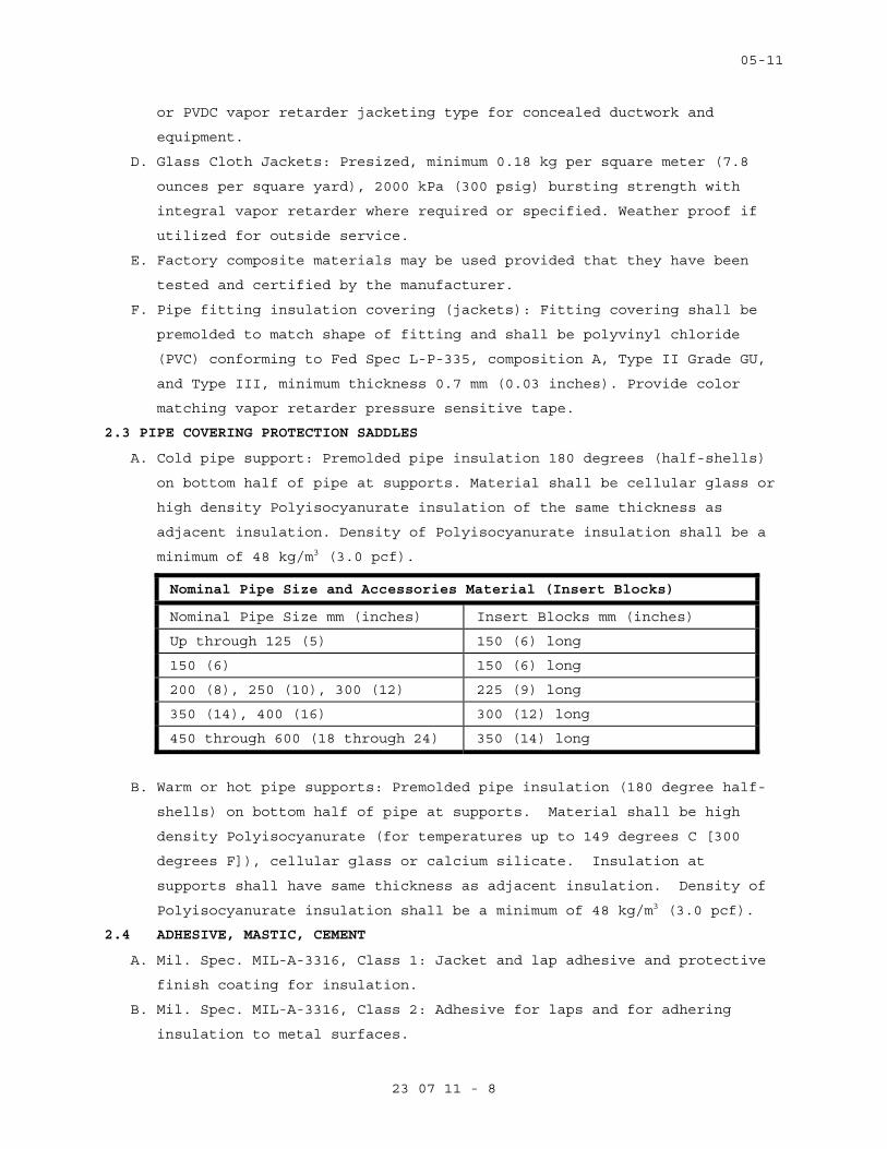
05-11
23 07 11 - 8
or PVDC vapor retarder jacketing type for concealed ductwork and
equipment.
D. Glass Cloth Jackets: Presized, minimum 0.18 kg per square meter (7.8
ounces per square yard), 2000 kPa (300 psig) bursting strength with
integral vapor retarder where required or specified. Weather proof if
utilized for outside service.
E. Factory composite materials may be used provided that they have been
tested and certified by the manufacturer.
F. Pipe fitting insulation covering (jackets): Fitting covering shall be
premolded to match shape of fitting and shall be polyvinyl chloride
(PVC) conforming to Fed Spec L-P-335, composition A, Type II Grade GU,
and Type III, minimum thickness 0.7 mm (0.03 inches). Provide color
matching vapor retarder pressure sensitive tape.
2.3 PIPE COVERING PROTECTION SADDLES
A. Cold pipe support: Premolded pipe insulation 180 degrees (half-shells)
on bottom half of pipe at supports. Material shall be cellular glass or
high density Polyisocyanurate insulation of the same thickness as
adjacent insulation. Density of Polyisocyanurate insulation shall be a
minimum of 48 kg/m3 (3.0 pcf).
Nominal Pipe Size and Accessories Material (Insert Blocks)
Nominal Pipe Size mm (inches) Insert Blocks mm (inches)
Up through 125 (5) 150 (6) long
150 (6) 150 (6) long
200 (8), 250 (10), 300 (12) 225 (9) long
350 (14), 400 (16) 300 (12) long
450 through 600 (18 through 24) 350 (14) long
B. Warm or hot pipe supports: Premolded pipe insulation (180 degree half-
shells) on bottom half of pipe at supports. Material shall be high
density Polyisocyanurate (for temperatures up to 149 degrees C [300
degrees F]), cellular glass or calcium silicate. Insulation at
supports shall have same thickness as adjacent insulation. Density of
Polyisocyanurate insulation shall be a minimum of 48 kg/m3 (3.0 pcf).
2.4 ADHESIVE, MASTIC, CEMENT
A. Mil. Spec. MIL-A-3316, Class 1: Jacket and lap adhesive and protective
finish coating for insulation.
B. Mil. Spec. MIL-A-3316, Class 2: Adhesive for laps and for adhering
insulation to metal surfaces.
05-11
23 07 11 - 9
C. Mil. Spec. MIL-A-24179, Type II Class 1: Adhesive for installing
flexible unicellular insulation and for laps and general use.
D. Mil. Spec. MIL-C-19565, Type I: Protective finish for outdoor use.
E. Mil. Spec. MIL-C-19565, Type I or Type II: Vapor barrier compound for
indoor use.
F. ASTM C449: Mineral fiber hydraulic-setting thermal insulating and
finishing cement.
G. Other: Insulation manufacturers' published recommendations.
2.5 MECHANICAL FASTENERS
A. Pins, anchors: Welded pins, or metal or nylon anchors with galvanized
steel-coated or fiber washer, or clips. Pin diameter shall be as
recommended by the insulation manufacturer.
B. Staples: Outward clinching galvanized steel.
C. Wire: 1.3 mm thick (18 gage) soft annealed galvanized or 1.9 mm (14
gage) copper clad steel or nickel copper alloy.
D. Bands: 13 mm (0.5 inch) nominal width, brass, galvanized steel,
aluminum or stainless steel.
2.6 REINFORCEMENT AND FINISHES
A. Glass fabric, open weave: ASTM D1668, Type III (resin treated) and Type
I (asphalt treated).
B. Glass fiber fitting tape: Mil. Spec MIL-C-20079, Type II, Class 1.
C. Tape for Flexible Elastomeric Cellular Insulation: As recommended by
the insulation manufacturer.
D. Hexagonal wire netting: 25 mm (one inch) mesh, 0.85 mm thick (22 gage)
galvanized steel.
E. Corner beads: 50 mm (2 inch) by 50 mm (2 inch), 0.55 mm thick (26 gage)
galvanized steel; or, 25 mm (1 inch) by 25 mm (1 inch), 0.47 mm thick
(28 gage) aluminum angle adhered to 50 mm (2 inch) by 50 mm (2 inch)
Kraft paper.
F. PVC fitting cover: Fed. Spec L-P-535, Composition A, 11-86 Type II,
Grade GU, with Form B Mineral Fiber insert, for media temperature 4
degrees C (40 degrees F) to 121 degrees C (250 degrees F). Below 4
degrees C (40 degrees F) and above 121 degrees C (250 degrees F).
Provide double layer insert. Provide color matching vapor barrier
pressure sensitive tape.
2.7 FIRESTOPPING MATERIAL
A. Other than pipe and duct insulation, refer to Section 07 84 00
FIRESTOPPING.
05-11
23 07 11 - 10
2.8 FLAME AND SMOKE
A. Unless shown otherwise all assembled systems shall meet flame spread 25
and smoke developed 50 rating as developed under ASTM, NFPA and UL
standards and specifications. See paragraph 1.3 "Quality Assurance".
PART 3 - EXECUTION
3.1 GENERAL REQUIREMENTS
A. Required pressure tests of piping joints and connections shall be
completed and the work approved by the COR for application of
insulation. Surface shall be clean and dry with all foreign materials,
such as dirt, oil, loose scale and rust removed.
B. Except for specific exceptions, insulate entire specified equipment,
piping (pipe, fittings, valves, accessories), and duct systems.
Insulate each pipe and duct individually. Do not use scrap pieces of
insulation where a full length section will fit.
C. Insulation materials shall be installed in a first class manner with
smooth and even surfaces, with jackets and facings drawn tight and
smoothly cemented down at all laps. Insulation shall be continuous
through all sleeves and openings, except at fire dampers and duct
heaters (NFPA 90A). Vapor retarders shall be continuous and
uninterrupted throughout systems with operating temperature 16 degrees
C (60 degrees F) and below. Lap and seal vapor retarder over ends and
exposed edges of insulation. Anchors, supports and other metal
projections through insulation on cold surfaces shall be insulated and
vapor sealed for a minimum length of 150 mm (6 inches).
D. Install vapor stops at all insulation terminations on either side of
valves, pumps and equipment and particularly in straight lengths of
pipe insulation.
E. Insulation on hot piping and equipment shall be terminated square at
items not to be insulated, access openings and nameplates. Cover all
exposed raw insulation with white sealer or jacket material.
F. HVAC work not to be insulated:
1. Internally insulated ductwork and air handling units.
2. Relief air ducts (Economizer cycle exhaust air).
3. Exhaust air ducts and plenums, and ventilation exhaust air shafts.
4. In hot piping: Unions, flexible connectors, control valves, exposed
piping through floor for convectors and radiators. Insulate piping
to within approximately 75 mm (3 inches) of uninsulated items.
05-11
23 07 11 - 11
G. Apply insulation materials subject to the manufacturer's recommended
temperature limits. Apply adhesives, mastic and coatings at the
manufacturer's recommended minimum coverage.
H. Elbows, flanges and other fittings shall be insulated with the same
material as is used on the pipe straights. The elbow/ fitting
insulation shall be field-fabricated, mitered or factory prefabricated
to the necessary size and shape to fit on the elbow/ fitting. Use of
polyurethane spray-foam to fill a PVC elbow jacket is prohibited on
cold applications.
I. Firestop Pipe and Duct insulation:
1. Provide firestopping insulation at fire and smoke barriers through
penetrations. Fire stopping insulation shall be UL listed as defines
in Section 07 84 00, FIRESTOPPING.
2. Pipe and duct penetrations requiring fire stop insulation including,
but not limited to the following:
a. Pipe risers through floors
b. Pipe or duct chase walls and floors
c. Smoke partitions
d. Fire partitions
J. Provide vapor barrier jackets over insulation as follows:
1. All interior piping conveying fluids below ambient air temperature.
3.2 INSULATION INSTALLATION
A. Molded Mineral Fiber Pipe and Tubing Covering:
1. Fit insulation to pipe or duct, aligning longitudinal joints. Seal
longitudinal joint laps and circumferential butt strips by rubbing
hard with a nylon sealing tool to assure a positive seal. Staples
may be used to assist in securing insulation. Seal all vapor
retarder penetrations on cold piping with a generous application of
vapor barrier mastic. Provide inserts and install with metal
insulation shields at outside pipe supports. Install freeze
protection insulation over heating cable.
2. Contractor's options for fitting, flange and valve insulation:
a. Insulating and finishing cement for sizes less than 100 mm (4
inches) operating at surface temperature of 16 degrees C (61
degrees F) or more.
b. Factory premolded, one piece PVC covers with mineral fiber, (Form
B), inserts. Provide two insert layers for pipe temperatures
below 4 degrees C (40 degrees F), or above 121 degrees C (250
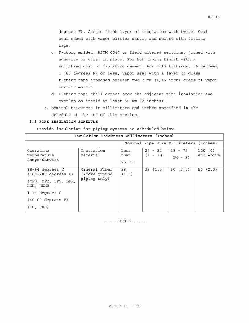
05-11
23 07 11 - 12
degrees F). Secure first layer of insulation with twine. Seal
seam edges with vapor barrier mastic and secure with fitting
tape.
c. Factory molded, ASTM C547 or field mitered sections, joined with
adhesive or wired in place. For hot piping finish with a
smoothing coat of finishing cement. For cold fittings, 16 degrees
C (60 degrees F) or less, vapor seal with a layer of glass
fitting tape imbedded between two 2 mm (1/16 inch) coats of vapor
barrier mastic.
d. Fitting tape shall extend over the adjacent pipe insulation and
overlap on itself at least 50 mm (2 inches).
3. Nominal thickness in millimeters and inches specified in the
schedule at the end of this section.
3.3 PIPE INSULATION SCHEDULE
Provide insulation for piping systems as scheduled below:
Insulation Thickness Millimeters (Inches)
Nominal Pipe Size Millimeters (Inches)
Operating Temperature Range/Service
Insulation Material
Less than
25 (1)
25 – 32 (1 – 1¼)
38 – 75
(1½ - 3)
100 (4) and Above
38-94 degrees C (100-200 degrees F)
(MPS, MPR, LPS, LPR, HWH, HWHR )
4-16 degrees C
(40-60 degrees F)
(CH, CHR)
Mineral Fiber (Above ground piping only)
38 (1.5)
38 (1.5) 50 (2.0) 50 (2.0)
- - - E N D - - -
09-11
23 09 23 - 1
SECTION 23 09 23 DIRECT-DIGITAL CONTROL SYSTEM FOR HVAC
PART 1 - GENERAL
1.1 DESCRIPTION
A. Provide direct-digital control system(s) as indicated on the project
documents, point list, interoperability tables, drawings, and as
described in these specifications. Include a complete and working
direct-digital control system. Include all engineering, programming,
controls and installation materials, installation labor, commissioning
and start-up, training, final project documentation and warranty.
1. The direct-digital control system(s) shall consist of high-speed,
peer-to-peer network of DDC controllers, a control system server, and
an Engineering Control Center. Provide a remote user using a standard
web browser to access the control system graphics and change
adjustable setpoints with the proper password.
2. The direct-digital control system(s) shall be native BACnet. All
new workstations, controllers, devices and components shall be listed
by BACnet Testing Laboratories. All new workstations, controller,
devices and components shall be accessible using a Web browser
interface and shall communicate exclusively using the ASHRAE Standard
135 BACnet communications protocol without the use of gateways,
unless otherwise allowed by this Section of the technical
specifications, specifically shown on the design drawings and
specifically requested otherwise by the VA.
a. If used, gateways shall support the ASHRAE Standard 135 BACnet
communications protocol.
b. If used, gateways shall provide all object properties and
read/write services shown on VA-approved interoperability
schedules.
3. The work administered by this Section of the technical
specifications shall include all labor, materials, special tools,
equipment, enclosures, power supplies, software, software licenses,
Project specific software configurations and database entries,
interfaces, wiring, tubing, installation, labeling, engineering,
calibration, documentation, submittals, testing, verification,
training services, permits and licenses, transportation, shipping,
handling, administration, supervision, management, insurance,
09-11
23 09 23 - 2
Warranty, specified services and items required for complete and
fully functional Controls Systems.
4. The control systems shall be designed such that each mechanical
system shall operate under stand-alone mode. The Contractor
administered by this Section of the technical specifications shall
provide controllers for each mechanical system. In the event of a
network communication failure, or the loss of any other controller,
the control system shall continue to operate independently. Failure
of the ECC shall have no effect on the field controllers, including
those involved with global strategies.
5. The control system shall accommodate multiple web-based users
simultaneously, and the access to the system should be congruent with
existing access control strategies.
B. Some products are furnished but not installed by the Contractor
administered by this Section of the technical specifications. The
Contractor administered by this Section of the technical specifications
shall formally coordinate in writing and receive from other Contractors
formal acknowledgements in writing prior to submission the installation
of the products. These products include the following:
1. Control valves.
2. Flow switches.
3. Flow meters.
4. Sensor wells and sockets in piping.
C. Some products are installed but not furnished by the Contractor
administered by this Section of the technical specifications. The
Contractor administered by this Section of the technical specifications
shall formally coordinate in writing and receive from other Contractors
formal acknowledgements in writing prior to submission the procurement
of the products. These products include the following:
1. Factory-furnished accessory thermostats and sensors furnished with
unitary equipment.
D. Some products are not provided by, but are nevertheless integrated with
the work executed by, the Contractor administered by this Section of
the technical specifications. The Contractor administered by this
Section of the technical specifications shall formally coordinate in
writing and receive from other Contractors formal acknowledgements in
writing prior to submission the particulars of the products. These
products include the following:
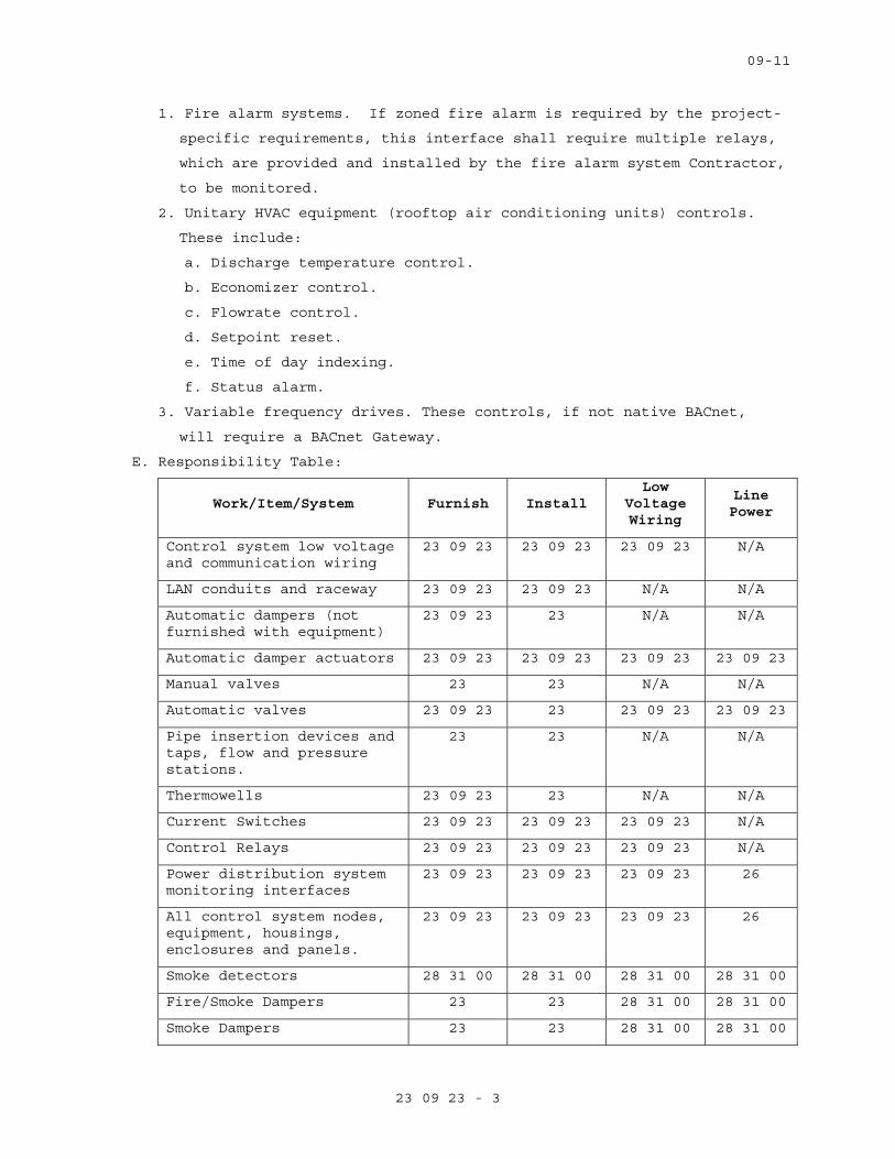
09-11
23 09 23 - 3
1. Fire alarm systems. If zoned fire alarm is required by the project-
specific requirements, this interface shall require multiple relays,
which are provided and installed by the fire alarm system Contractor,
to be monitored.
2. Unitary HVAC equipment (rooftop air conditioning units) controls.
These include:
a. Discharge temperature control.
b. Economizer control.
c. Flowrate control.
d. Setpoint reset.
e. Time of day indexing.
f. Status alarm.
3. Variable frequency drives. These controls, if not native BACnet,
will require a BACnet Gateway.
E. Responsibility Table:
Work/Item/System Furnish Install Low
Voltage Wiring
Line Power
Control system low voltage and communication wiring
23 09 23 23 09 23 23 09 23 N/A
LAN conduits and raceway 23 09 23 23 09 23 N/A N/A
Automatic dampers (not furnished with equipment)
23 09 23 23 N/A N/A
Automatic damper actuators 23 09 23 23 09 23 23 09 23 23 09 23
Manual valves 23 23 N/A N/A
Automatic valves 23 09 23 23 23 09 23 23 09 23
Pipe insertion devices and taps, flow and pressure stations.
23 23 N/A N/A
Thermowells 23 09 23 23 N/A N/A
Current Switches 23 09 23 23 09 23 23 09 23 N/A
Control Relays 23 09 23 23 09 23 23 09 23 N/A
Power distribution system monitoring interfaces
23 09 23 23 09 23 23 09 23 26
All control system nodes, equipment, housings, enclosures and panels.
23 09 23 23 09 23 23 09 23 26
Smoke detectors 28 31 00 28 31 00 28 31 00 28 31 00
Fire/Smoke Dampers 23 23 28 31 00 28 31 00
Smoke Dampers 23 23 28 31 00 28 31 00

09-11
23 09 23 - 4
Work/Item/System Furnish Install Low
Voltage Wiring
Line Power
Fire Dampers 23 23 N/A N/A
VFDs 23 09 23 26 23 09 23 26
Fire Alarm shutdown relay interlock wiring
28 28 28 26
Control system monitoring of fire alarm smoke control relay
28 28 23 09 23 28
Fire-fighter’s smoke control station (FSCS
28 28 28 28
Starters, HOA switches 23 23 N/A 26
F. This facility has three existing direct-digital control systems, the
first is manufactured by Johnson Controls, the second is manufactured
by Alerton, and the third is Tridium Niagra. The Johnson Controls
Metasys ECC is located at HVAC Shop GB1-08 and at Chiller Plant Office
E1101.
1. The existing Johnson Controls system top-end communications shall
remain in place with only the local associated A/C controls removed.
The existing system’s ECC and top-end controllers were installed in
1990-1995.
2. The Contractor administered by this Section of the technical
specifications shall observe the capabilities, communication network,
services, spare capacity of the existing control systems and its ECC
prior to beginning work.
3. Leave existing direct-digital control system intact and in place.
Provide a new ASHRAE Standard 135 BACnet-compliant ECC in the same
room as the existing system’s ECC, and provide a new standalone
BACnet-compliant control system serving the work in this project. No
interoperability is required with existing Johnson Control system.
4. Modify existing Tridium system as required to accommodate all new
components as specified. Modifications include, but are not limited
to, graphics modifications to accommodate new spaces and equipment,
operating sequences, scheduling, and setpoints.
5. Alerton system shall be integrated into existing Tridium system.
Replace BCM with JACE interface modules as identified in project
drawings. Upon integration of Alerton local controls into Tridium
system, Alerton head end shall be decommissioned. The BCM’s and
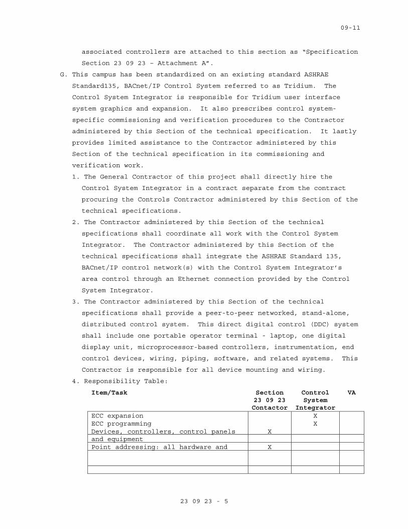
09-11
23 09 23 - 5
associated controllers are attached to this section as “Specification
Section 23 09 23 – Attachment A”.
G. This campus has been standardized on an existing standard ASHRAE
Standard135, BACnet/IP Control System referred to as Tridium. The
Control System Integrator is responsible for Tridium user interface
system graphics and expansion. It also prescribes control system-
specific commissioning and verification procedures to the Contractor
administered by this Section of the technical specification. It lastly
provides limited assistance to the Contractor administered by this
Section of the technical specification in its commissioning and
verification work.
1. The General Contractor of this project shall directly hire the
Control System Integrator in a contract separate from the contract
procuring the Controls Contractor administered by this Section of the
technical specifications.
2. The Contractor administered by this Section of the technical
specifications shall coordinate all work with the Control System
Integrator. The Contractor administered by this Section of the
technical specifications shall integrate the ASHRAE Standard 135,
BACnet/IP control network(s) with the Control System Integrator’s
area control through an Ethernet connection provided by the Control
System Integrator.
3. The Contractor administered by this Section of the technical
specifications shall provide a peer-to-peer networked, stand-alone,
distributed control system. This direct digital control (DDC) system
shall include one portable operator terminal - laptop, one digital
display unit, microprocessor-based controllers, instrumentation, end
control devices, wiring, piping, software, and related systems. This
Contractor is responsible for all device mounting and wiring.
4. Responsibility Table:
Item/Task Section 23 09 23 Contactor
Control System
Integrator
VA
ECC expansion X ECC programming X Devices, controllers, control panels and equipment
X
Point addressing: all hardware and X
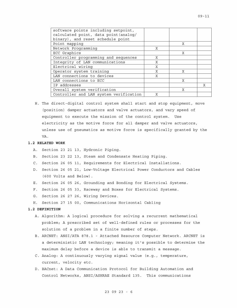
09-11
23 09 23 - 6
software points including setpoint, calculated point, data point(analog/ binary), and reset schedule point Point mapping X Network Programming X ECC Graphics X Controller programming and sequences X Integrity of LAN communications X Electrical wiring X Operator system training X X LAN connections to devices X LAN connections to ECC X IP addresses X Overall system verification X Controller and LAN system verification X
H. The direct-digital control system shall start and stop equipment, move
(position) damper actuators and valve actuators, and vary speed of
equipment to execute the mission of the control system. Use
electricity as the motive force for all damper and valve actuators,
unless use of pneumatics as motive force is specifically granted by the
VA.
1.2 RELATED WORK
A. Section 23 21 13, Hydronic Piping.
B. Section 23 22 13, Steam and Condensate Heating Piping.
C. Section 26 05 11, Requirements for Electrical Installations.
D. Section 26 05 21, Low-Voltage Electrical Power Conductors and Cables
(600 Volts and Below).
E. Section 26 05 26, Grounding and Bonding for Electrical Systems.
F. Section 26 05 33, Raceway and Boxes for Electrical Systems.
G. Section 26 27 26, Wiring Devices.
H. Section 27 15 00, Communications Horizontal Cabling
1.2 DEFINITION
A. Algorithm: A logical procedure for solving a recurrent mathematical
problem; A prescribed set of well-defined rules or processes for the
solution of a problem in a finite number of steps.
B. ARCNET: ANSI/ATA 878.1 - Attached Resource Computer Network. ARCNET is
a deterministic LAN technology; meaning it's possible to determine the
maximum delay before a device is able to transmit a message.
C. Analog: A continuously varying signal value (e.g., temperature,
current, velocity etc.
D. BACnet: A Data Communication Protocol for Building Automation and
Control Networks, ANSI/ASHRAE Standard 135. This communications
09-11
23 09 23 - 7
protocol allows diverse building automation devices to communicate data
over and services over a network.
E. BACnet/IP: Annex J of Standard 135. It defines and allows for using a
reserved UDP socket to transmit BACnet messages over IP networks. A
BACnet/IP network is a collection of one or more IP sub-networks that
share the same BACnet network number.
F. BACnet Internetwork: Two or more BACnet networks connected with
routers. The two networks may sue different LAN technologies.
G. BACnet Network: One or more BACnet segments that have the same network
address and are interconnected by bridges at the physical and data link
layers.
H. BACnet Segment: One or more physical segments of BACnet devices on a
BACnet network, connected at the physical layer by repeaters.
I. BACnet Broadcast Management Device (BBMD): A communications device
which broadcasts BACnet messages to all BACnet/IP devices and other
BBMDs connected to the same BACnet/IP network.
J. BACnet Interoperability Building Blocks (BIBBs): BACnet
Interoperability Building Blocks (BIBBs) are collections of one or more
BACnet services. These are prescribed in terms of an "A" and a "B"
device. Both of these devices are nodes on a BACnet internetwork.
K. BACnet Testing Laboratories (BTL). The organization responsible for
testing products for compliance with the BACnet standard, operated
under the direction of BACnet International.
L. Baud: It is a signal change in a communication link. One signal change
can represent one or more bits of information depending on type of
transmission scheme. Simple peripheral communication is normally one
bit per Baud. (e.g., Baud rate = 78,000 Baud/sec is 78,000 bits/sec, if
one signal change = 1 bit).
M. Binary: A two-state system where a high signal level represents an "ON"
condition and an "OFF" condition is represented by a low signal level.
N. BMP or bmp: Suffix, computerized image file, used after the period in a
DOS-based computer file to show that the file is an image stored as a
series of pixels.
O. Bus Topology: A network topology that physically interconnects
workstations and network devices in parallel on a network segment.
P. Control Unit (CU): Generic term for any controlling unit, stand-alone,
microprocessor based, digital controller residing on secondary LAN or
Primary LAN, used for local controls or global controls
09-11
23 09 23 - 8
Q. Deadband: A temperature range over which no heating or cooling is
supplied, i.e., 22-25 degrees C (72-78 degrees F), as opposed to a
single point change over or overlap).
R. Device: a control system component that contains a BACnet Device Object
and uses BACnet to communicate with other devices.
S. Device Object: Every BACnet device requires one Device Object, whose
properties represent the network visible properties of that device.
Every Device Object requires a unique Object Identifier number on the
BACnet internetwork. This number is often referred to as the device
instance.
T. Device Profile: A specific group of services describing BACnet
capabilities of a device, as defined in ASHRAE Standard 135-2008, Annex
L. Standard device profiles include BACnet Operator Workstations (B-
OWS), BACnet Building Controllers (B-BC), BACnet Advanced Application
Controllers (B-AAC), BACnet Application Specific Controllers (B-ASC),
BACnet Smart Actuator (B-SA), and BACnet Smart Sensor (B-SS). Each
device used in new construction is required to have a PICS statement
listing which service and BIBBs are supported by the device.
U. Diagnostic Program: A software test program, which is used to detect
and report system or peripheral malfunctions and failures. Generally,
this system is performed at the initial startup of the system.
V. Direct Digital Control (DDC): Microprocessor based control including
Analog/Digital conversion and program logic. A control loop or
subsystem in which digital and analog information is received and
processed by a microprocessor, and digital control signals are
generated based on control algorithms and transmitted to field devices
in order to achieve a set of predefined conditions.
W. Distributed Control System: A system in which the processing of system
data is decentralized and control decisions can and are made at the
subsystem level. System operational programs and information are
provided to the remote subsystems and status is reported back to the
Engineering Control Center. Upon the loss of communication with the
Engineering Control center, the subsystems shall be capable of
operating in a stand-alone mode using the last best available data.
X. Download: The electronic transfer of programs and data files from a
central computer or operation workstation with secondary memory devices
to remote computers in a network (distributed) system.
09-11
23 09 23 - 9
Y. DXF: An AutoCAD 2-D graphics file format. Many CAD systems import and
export the DXF format for graphics interchange.
Z. Electrical Control: A control circuit that operates on line or low
voltage and uses a mechanical means, such as a temperature sensitive
bimetal or bellows, to perform control functions, such as actuating a
switch or positioning a potentiometer.
AA. Electronic Control: A control circuit that operates on low voltage and
uses a solid-state components to amplify input signals and perform
control functions, such as operating a relay or providing an output
signal to position an actuator.
BB. Engineering Control Center (ECC): The centralized control point for the
intelligent control network. The ECC comprises of personal computer and
connected devices to form a single workstation.
CC. Ethernet: A trademark for a system for exchanging messages between
computers on a local area network using coaxial, fiber optic, or
twisted-pair cables.
DD. Firmware: Firmware is software programmed into read only memory (ROM)
chips. Software may not be changed without physically altering the
chip.
EE. Gateway: Communication hardware connecting two or more different
protocols. It translates one protocol into equivalent concepts for the
other protocol. In BACnet applications, a gateway has BACnet on one
side and non-BACnet (usually proprietary) protocols on the other side.
FF. GIF: Abbreviation of Graphic interchange format.
GG. Graphic Program (GP): Program used to produce images of air handler
systems, fans, chillers, pumps, and building spaces. These images can
be animated and/or color-coded to indicate operation of the equipment.
HH. Graphic Sequence of Operation: It is a graphical representation of the
sequence of operation, showing all inputs and output logical blocks.
II. I/O Unit: The section of a digital control system through which
information is received and transmitted. I/O refers to analog input
(AI, digital input (DI), analog output (AO) and digital output (DO).
Analog signals are continuous and represent temperature, pressure, flow
rate etc, whereas digital signals convert electronic signals to digital
pulses (values), represent motor status, filter status, on-off
equipment etc.
JJ. I/P: a method for conveying and routing packets of information over LAN
paths. User Datagram Protocol (UDP) conveys information to “sockets”
09-11
23 09 23 - 10
without confirmation of receipt. Transmission Control Protocol (TCP)
establishes "sessions", which have end-to-end confirmation and
guaranteed sequence of delivery.
KK. JPEG: A standardized image compression mechanism stands for Joint
Photographic Experts Group, the original name of the committee that
wrote the standard.
LL. Local Area Network (LAN): A communication bus that interconnects
operator workstation and digital controllers for peer-to-peer
communications, sharing resources and exchanging information.
MM. Network Repeater: A device that receives data packet from one network
and rebroadcasts to another network. No routing information is added to
the protocol.
NN. MS/TP: Master-slave/token-passing (ISO/IEC 8802, Part 3). It is not an
acceptable LAN option for VA health-care facilities. It uses twisted-
pair wiring for relatively low speed and low cost communication.
OO. Native BACnet Device: A device that uses BACnet as its primary method
of communication with other BACnet devices without intermediary
gateways. A system that uses native BACnet devices at all levels is a
native BACnet system.
PP. Network Number: A site-specific number assigned to each network segment
to identify for routing. This network number must be unique throughout
the BACnet internetwork.
QQ. Object: The concept of organizing BACnet information into standard
components with various associated properties. Examples include analog
input objects and binary output objects.
RR. Object Identifier: An object property used to identify the object,
including object type and instance. Object Identifiers must be unique
within a device.
SS. Object Properties: Attributes of an object. Examples include present
value and high limit properties of an analog input object. Properties
are defined in ASHRAE 135; some are optional and some are required.
Objects are controlled by reading from and writing to object
properties.
TT. Operating system (OS): Software, which controls the execution of
computer application programs.
UU. PCX: File type for an image file. When photographs are scanned onto a
personal computer they can be saved as PCX files and viewed or changed
by a special application program as Photo Shop.
09-11
23 09 23 - 11
VV. Peripheral: Different components that make the control system function
as one unit. Peripherals include monitor, printer, and I/O unit.
WW. Peer-to-Peer: A networking architecture that treats all network
stations as equal partners- any device can initiate and respond to
communication with other devices.
XX. PICS: Protocol Implementation Conformance Statement, describing the
BACnet capabilities of a device. All BACnet devices have published
PICS.
YY. PID: Proportional, integral, and derivative control, used to control
modulating equipment to maintain a setpoint.
ZZ. Repeater: A network component that connects two or more physical
segments at the physical layer.
AAA. Router: a component that joins together two or more networks using
different LAN technologies. Examples include joining a BACnet Ethernet
LAN to a BACnet MS/TP LAN.
BBB. Sensors: devices measuring state points or flows, which are then
transmitted back to the DDC system.
CCC. Thermostats : devices measuring temperatures, which are used in control
of standalone or unitary systems and equipment not attached to the DDC
system.
1.4 QUALITY ASSURANCE
A. Criteria:
1. Single Source Responsibility of Sub-Contractor: The Contractor shall
obtain hardware and software supplied under this Section and
delegate the responsibility to a single source controls installation
Sub-Contractor. The controls Sub-Contractor shall be responsible for
the complete design, installation, and commissioning of the system.
The controls Sub-Contractor shall be in the business of design,
installation and service of such building automation control systems
similar in size and complexity.
2. Equipment and Materials: Equipment and materials shall be cataloged
products of manufacturers regularly engaged in production and
installation of HVAC control systems. Products shall be
manufacturer’s latest standard design and have been tested and
proven in actual use.
09-11
23 09 23 - 12
3. The controls Sub-Contractor shall have minimum of three years experience in design and installation of building automation systems
similar in performance to those specified in this Section. Provide
evidence of experience by submitting resumes of the project manager,
the local branch manager, project engineer, the application
engineering staff, and the electronic technicians who would be
involved with the supervision, the engineering, and the installation
of the control systems. Training and experience of these personnel
shall not be less than three years. Failure to disclose this
information will be a ground for disqualification of the supplier.
4. Provide a competent and experienced Project Manager employed by the Controls Contractor. The Project Manager shall be supported as
necessary by other Contractor employees in order to provide
professional engineering, technical and management service for the
work. The Project Manager shall attend scheduled Project Meetings as
required and shall be empowered to make technical, scheduling and
related decisions on behalf of the Controls Contractor.
B. Codes and Standards:
1. All work shall conform to the applicable Codes and Standards.
2. Electronic equipment shall conform to the requirements of FCC
Regulation, Part 15, Governing Radio Frequency Electromagnetic
Interference, and be so labeled. C.Providers Qualification's1. Controls Integrator shall be VYKON System Integrator, certified Triduium trainer and VYKON Energy Reseller. Provider listing is available at:http://www.tridium.com/cs/purchase_products/north_america2. Controls Provider shall be a major controls manufacturer.
1.5 PERFORMANCE
A. The system shall conform to the following:
1. Graphic Display: The system shall display up to four (4) graphics on
a single screen with a minimum of twenty (20) dynamic points per
graphic. All current data shall be displayed within ten (10) seconds
of the request.
2. Graphic Refresh: The system shall update all dynamic points with
current data within eight (8) seconds. Data refresh shall be
automatic, without operator intervention.
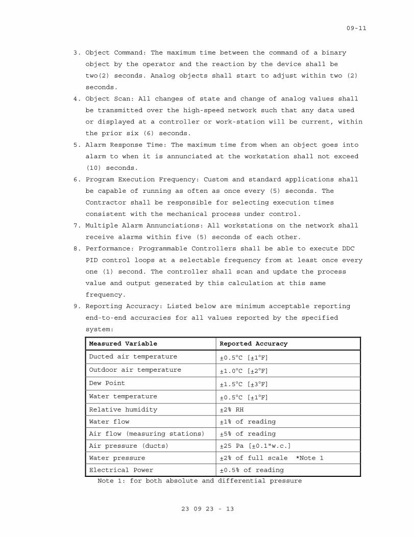
09-11
23 09 23 - 13
3. Object Command: The maximum time between the command of a binary
object by the operator and the reaction by the device shall be
two(2) seconds. Analog objects shall start to adjust within two (2)
seconds.
4. Object Scan: All changes of state and change of analog values shall
be transmitted over the high-speed network such that any data used
or displayed at a controller or work-station will be current, within
the prior six (6) seconds.
5. Alarm Response Time: The maximum time from when an object goes into
alarm to when it is annunciated at the workstation shall not exceed
(10) seconds.
6. Program Execution Frequency: Custom and standard applications shall
be capable of running as often as once every (5) seconds. The
Contractor shall be responsible for selecting execution times
consistent with the mechanical process under control.
7. Multiple Alarm Annunciations: All workstations on the network shall
receive alarms within five (5) seconds of each other.
8. Performance: Programmable Controllers shall be able to execute DDC
PID control loops at a selectable frequency from at least once every
one (1) second. The controller shall scan and update the process
value and output generated by this calculation at this same
frequency.
9. Reporting Accuracy: Listed below are minimum acceptable reporting
end-to-end accuracies for all values reported by the specified
system:
Measured Variable Reported Accuracy
Ducted air temperature ±0.5°C [±1°F]
Outdoor air temperature ±1.0°C [±2°F]
Dew Point ±1.5°C [±3°F]
Water temperature ±0.5°C [±1°F]
Relative humidity ±2% RH
Water flow ±1% of reading
Air flow (measuring stations) ±5% of reading
Air pressure (ducts) ±25 Pa [±0.1"w.c.]
Water pressure ±2% of full scale *Note 1
Electrical Power ±0.5% of reading
Note 1: for both absolute and differential pressure
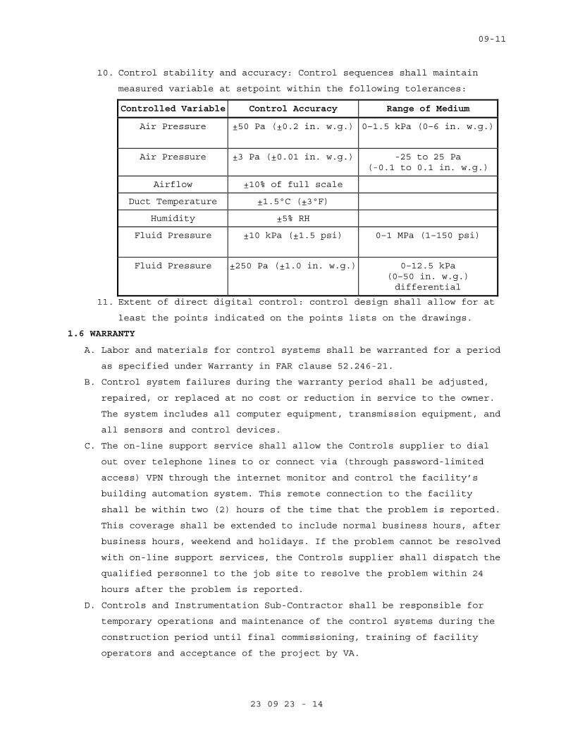
09-11
23 09 23 - 14
10. Control stability and accuracy: Control sequences shall maintain
measured variable at setpoint within the following tolerances:
Controlled Variable Control Accuracy Range of Medium
Air Pressure ±50 Pa (±0.2 in. w.g.)
0–1.5 kPa (0–6 in. w.g.)
Air Pressure ±3 Pa (±0.01 in. w.g.) -25 to 25 Pa (-0.1 to 0.1 in. w.g.)
Airflow ±10% of full scale
Duct Temperature ±1.5ºC (±3ºF)
Humidity ±5% RH
Fluid Pressure ±10 kPa (±1.5 psi)
0–1 MPa (1–150 psi)
Fluid Pressure ±250 Pa (±1.0 in. w.g.) 0–12.5 kPa (0–50 in. w.g.) differential
11. Extent of direct digital control: control design shall allow for at
least the points indicated on the points lists on the drawings.
1.6 WARRANTY
A. Labor and materials for control systems shall be warranted for a period
as specified under Warranty in FAR clause 52.246-21.
B. Control system failures during the warranty period shall be adjusted,
repaired, or replaced at no cost or reduction in service to the owner.
The system includes all computer equipment, transmission equipment, and
all sensors and control devices.
C. The on-line support service shall allow the Controls supplier to dial
out over telephone lines to or connect via (through password-limited
access) VPN through the internet monitor and control the facility’s
building automation system. This remote connection to the facility
shall be within two (2) hours of the time that the problem is reported.
This coverage shall be extended to include normal business hours, after
business hours, weekend and holidays. If the problem cannot be resolved
with on-line support services, the Controls supplier shall dispatch the
qualified personnel to the job site to resolve the problem within 24
hours after the problem is reported.
D. Controls and Instrumentation Sub-Contractor shall be responsible for
temporary operations and maintenance of the control systems during the
construction period until final commissioning, training of facility
operators and acceptance of the project by VA.
09-11
23 09 23 - 15
1.7 SUBMITTALS
A. Submit shop drawings in accordance with Section 01 33 23, SHOP
DRAWINGS, PRODUCT DATA, AND SAMPLES.
B. Manufacturer’s literature and data for all components including the
following:
1. A wiring diagram for each type of input device and output device
including DDC controllers, modems, repeaters, etc. Diagram shall
show how the device is wired and powered, showing typical
connections at the digital controllers and each power supply, as
well as the device itself. Show for all field connected devices,
including but not limited to, control relays, motor starters,
electric or electronic actuators, and temperature pressure, flow and
humidity sensors and transmitters.
2. A diagram of each terminal strip, including digital controller
terminal strips, terminal strip location, termination numbers and
the associated point names.
3. Control dampers and control valves schedule, including the size and
pressure drop.
4. Control air-supply components, and computations for sizing
compressors, receivers and main air-piping, if pneumatic controls
are furnished.
5. Catalog cut sheets of all equipment used. This includes, but is not
limited to software (by manufacturer and by third parties), DDC
controllers, panels, peripherals, airflow measuring stations and
associated components, and auxiliary control devices such as
sensors, actuators, and control dampers. When manufacturer’s cut
sheets apply to a product series rather than a specific product, the
data specifically applicable to the project shall be highlighted.
Each submitted piece of literature and drawings should clearly
reference the specification and/or drawings that it supposed to
represent.
6. Sequence of operations for each HVAC system and the associated
control diagrams. Equipment and control labels shall correspond to
those shown on the drawings.
7. Color prints of proposed graphics with a list of points for display.
8. Furnish a BACnet Protocol Implementation Conformance Statement
(PICS) for each BACnet-compliant device.
09-11
23 09 23 - 16
9. Schematic wiring diagrams for all control, communication and power
wiring. Provide a schematic drawing of the central system
installation. Label all cables and ports with computer
manufacturers’ model numbers and functions. Show all interface
wiring to the control system.
10. An instrumentation list for each controlled system. Each element of
the controlled system shall be listed in table format. The table
shall show element name, type of device, manufacturer, model number,
and product data sheet number.
11. Riser diagrams of wiring between central control unit and all
control panels.
12. Scaled plan drawings showing routing of LAN and locations of control
panels, controllers, routers, gateways, ECC, and larger controlled
devices.
13. Construction details for all installed conduit, cabling, raceway,
cabinets, and similar. Construction details of all penetrations and
their protection.
14. Quantities of submitted items may be reviewed but are the
responsibility of the Contractor administered by this Section of the
technical specifications.
15. Computer graphics associated with system(s) shall be in place and
approved prior to disconnection of system being replaced.
C. Product Certificates: Compliance with Article, QUALITY ASSURANCE.
D. Licenses: Provide licenses for all software residing on and used by the
Controls Systems and transfer these licenses to the Owner prior to
completion.
E. As Built Control Drawings:
1. Furnish three (3) copies of as-built drawings for each control
system. The documents shall be submitted for approval prior to final
completion.
2. Furnish one (1) CD-ROM in CAD DWG and/or .DXF format for the
drawings noted in subparagraphs above.
F. Submittal for laptop shall be provided demonstrating the capacity to
operate the software required to interface with local controls and to
document the software that shall be installed. Laptop shall be utilized
for O/M training of operating staff and shall be left with COR.
G. Operation and Maintenance (O/M) Manuals):
09-11
23 09 23 - 17
1. Submit in accordance with Article, INSTRUCTIONS, in Specification
Section 01 00 00, GENERAL REQUIREMENTS.
2. Include the following documentation:
a. General description and specifications for all components,
including procedures for logging on/off, alarm handling,
producing trend reports, overriding computer control, and
changing set points and other variables.
b. Detailed illustrations of all the control systems specified for
ease of maintenance and repair/replacement procedures, and
complete calibration procedures.
c. One copy of the final version of all software provided including
operating systems, programming language, operator workstation
software, and graphics software.
d. Complete troubleshooting procedures and guidelines for all
systems.
e. Complete operating instructions for all systems.
f. Recommended preventive maintenance procedures for all system
components including a schedule of tasks for inspection, cleaning
and calibration. Provide a list of recommended spare parts needed
to minimize downtime.
g. Training Manuals: Submit the course outline and training material
to the Owner for approval three (3) weeks prior to the training
to VA facility personnel. These persons will be responsible for
maintaining and the operation of the control systems, including
programming. The Owner reserves the right to modify any or all of
the course outline and training material.
h. Licenses, guaranty, and other pertaining documents for all
equipment and systems.
H. Submit Performance Report to COR prior to final inspection.
1.8 INSTRUCTIONS
A. Instructions to VA operations personnel: Perform in accordance with
Article, INSTRUCTIONS, in Specification Section 01 00 00, GENERAL
REQUIREMENTS, and as noted below. Contractor shall also video tape
instruction sessions noted below.
1. First Phase: Formal instructions to the VA facilities personnel for
a total of no less than 48 hours, given in multiple training
sessions (each no longer than four hours in length each), conducted
between the completed installation and prior to the performance test
09-11
23 09 23 - 18
period of the control system, at a time mutually agreeable to the
Contractor and the VA.
a. (2) Four hour training sessions by System Head-End Manufacturer
shall be provided, which are identical, with the intent of
allowing for flexibility of operating staff scheduling. Session
shall be professionally video recorded for future use. Head end
training shall be facilitated and attended by System Integrator.
System Integrator shall coordinate scheduling with COR.
2. Second Phase: This phase of training shall comprise of on the job
training during start-up, checkout period, and performance test
period. VA facilities personnel will work with the Contractor’s
installation and test personnel on a daily basis during start-up and
checkout period. During the performance test period, controls Sub-
Contractor will provide 48 hours of instructions, given in multiple
training sessions (each no longer than four hours in length), to the
VA facilities personnel.
a. Control contractor shall provide five eight-hour training
sessions during a period of one week for three designated
representatives of the operating staff. Contractor shall
coordinate with COR for representatives of the operating staff
and scheduling.
3. The O/M Manuals shall contain approved submittals as outlined in
Article 1.7, SUBMITTALS. The Controls Sub-Contractor will review the
manual contents with VA facilities personnel during second phase of
training.
a. Controls Sub-Contractor shall provide one laptop with the
operating capacity and software required to be utilized in the
second phase training and review of O/M Manuals. Laptop shall be
used to demonstrate direct connection to local control panel and
local control access.
4. Training shall be given by direct employees of the controls system
Sub-Contractor.
1.9 PROJECT CONDITIONS (ENVIRONMENTAL CONDITIONS OF OPERATION)
A. The ECC and peripheral devices and system support equipment shall be
designed to operate in ambient condition of 20 to 35°C (65 to 90°F) at a
relative humidity of 20 to 80% non-condensing.
B. The CUs used outdoors shall be mounted in NEMA 4 waterproof enclosures,
and shall be rated for operation at –40 to 65°C (-40 to 150°F).
09-11
23 09 23 - 19
C. All electronic equipment shall operate properly with power fluctuations
of plus 10 percent to minus 15 percent of nominal supply voltage.
D. Sensors and controlling devices shall be designed to operate in the
environment, which they are sensing or controlling.
1.10 APPLICABLE PUBLICATIONS
A. The publications listed below form a part of this specification to the
extent referenced. The publications are referenced in the text by the
basic designation only.
B. American Society of Heating, Refrigerating, and Air-Conditioning
Engineers (ASHRAE):
Standard 135-10.........BACNET Building Automation and Control Networks
C. American Society of Mechanical Engineers (ASME):
B16.18-01...............Cast Copper Alloy Solder Joint Pressure Fittings.
B16.22-01...............Wrought Copper and Copper Alloy Solder Joint Pressure Fittings.
D. American Society of Testing Materials (ASTM):
B32-08..................Standard Specification for Solder Metal B88-09..................Standard Specifications for Seamless Copper
Water Tube B88M-09.................Standard Specification for Seamless Copper
Water Tube (Metric) B280-08.................Standard Specification for Seamless Copper Tube
for Air-Conditioning and Refrigeration Field Service
D2737-03................Standard Specification for Polyethylene (PE) Plastic Tubing
E. Federal Communication Commission (FCC):
Rules and Regulations Title 47 Chapter 1-2001 Part 15: Radio Frequency Devices.
F. Institute of Electrical and Electronic Engineers (IEEE):
802.3-11................Information Technology-Telecommunications and Information Exchange between Systems-Local and Metropolitan Area Networks- Specific Requirements-Part 3: Carrier Sense Multiple Access with Collision Detection (CSMA/CD) Access method and Physical Layer Specifications
G. National Fire Protection Association (NFPA):
70-11...................National Electric Code 90A-09..................Standard for Installation of Air-Conditioning
and Ventilation Systems
H. Underwriter Laboratories Inc (UL):
09-11
23 09 23 - 20
94-10...................Tests for Flammability of Plastic Materials for Parts and Devices and Appliances
294-10..................Access Control System Units 486A/486B-10............Wire Connectors 555S-11.................Standard for Smoke Dampers 916-10..................Energy Management Equipment 1076-10.................Proprietary Burglar Alarm Units and Systems
PART 2 - PRODUCTS
2.1 MATERIALS
A. Use new products that the manufacturer is currently manufacturing and
that have been installed in a minimum of 25 installations. Spare parts
shall be available for at least five years after completion of this
contract.
2.2 CONTROLS SYSTEM ARCHITECTURE
A. General
1. The Controls Systems shall consist of multiple Nodes and associated
equipment connected by industry standard digital and communication
network arrangements.
2. The ECC, building controllers and principal communications network
equipment shall be standard products of recognized major
manufacturers available through normal PC and computer vendor
channels – not "Clones" assembled by a third-party Sub-Contractor.
3. The networks shall, at minimum, comprise, as necessary, the
following:
a. A fixed ECC and a portable operator’s terminal.
b. Network computer processing, data storage and BACnet-compliant
communication equipment including Servers and digital data
processors.
c. BACnet-compliant routers, bridges, switches, hubs, modems,
gateways, interfaces and similar communication equipment.
d. Active processing BACnet-compliant building controllers connected
to other BACNet-compliant controllers together with their power
supplies and associated equipment.
e. Addressable elements, sensors, transducers and end devices.
f. Third-party equipment interfaces and gateways as described and
required by the Contract Documents.
g. Other components required for a complete and working Control
Systems as specified.
B. The Specifications for the individual elements and component subsystems
shall be minimum requirements and shall be augmented as necessary by
09-11
23 09 23 - 21
the Contractor to achieve both compliance with all applicable codes,
standards and to meet all requirements of the Contract Documents.
C. Network Architecture
1. The Controls communication network shall utilize BACnet
communications protocol operating over a standard Ethernet LAN and
operate at a minimum speed of 100 Mb/sec.
2. The networks shall utilize only copper and optical fiber
communication media as appropriate and shall comply with applicable
codes, ordinances and regulations. They may also utilize digital
wireless technologies as appropriate to the application and if
approved by the VA.
3. All necessary telephone lines, ISDN lines and internet Service
Provider services and connections will be provided by the VA.
D. Third Party Interfaces:
1. The Contractor administered by this Section of the technical
specifications shall include necessary hardware, equipment, software
and programming to allow data communications between the controls
systems and building systems supplied by other trades.
2. Other manufacturers and Contractors supplying other associated
systems and equipment shall provide their necessary hardware,
software and start-up at their cost and shall cooperate fully with
the Contractor administered by this Section of the technical
specifications in a timely manner and at their cost to ensure
complete functional integration.
2.3 COMMUNICATION
A. Control products, communication media, connectors, repeaters, hubs, and
routers shall comprise a BACnet internetwork. Controller and operator
interface communication shall conform to ANSI/ASHRAE Standard 135-2008,
BACnet.
1. The Data link / physical layer protocol (for communication)
acceptable to the VA throughout its facilities is Ethernet (ISO
8802-3) and BACnet/IP.
2. The MS/TP data link / physical layer protocol is not acceptable to
the VA in any new BACnet network or sub-network in its healthcare or
lab facilities.
B. Each controller shall have a communication port for connection to an
operator interface.
09-11
23 09 23 - 22
C. Project drawings indicate future remote buildings or sites to be
connected by a nominal 56,000 baud modem over voice-grade telephone
lines. In each remote location a modem and field device connection
shall allow communication with each controller on the internetwork as
specified in Paragraph D.
D. Internetwork operator interface and value passing shall be transparent
to internetwork architecture.
1. An operator interface connected to a controller shall allow the
operator to interface with each internetwork controller as if
directly connected. Controller information such as data, status,
reports, system software, and custom programs shall be viewable and
editable from each internetwork controller.
2. Inputs, outputs, and control variables used to integrate control
strategies across multiple controllers shall be readable by each
controller on the internetwork. Program and test all cross-
controller links required to execute specified control system
operation. An authorized operator shall be able to edit cross-
controller links by typing a standard object address.
E. System shall be expandable to at least twice the required input and
output objects with additional controllers, associated devices, and
wiring. Expansion shall not require operator interface hardware
additions or software revisions.
F. ECCs and Controllers with real-time clocks shall use the BACnet Time
Synchronization service. The system shall automatically synchronize
system clocks daily from an operator-designated device via the
internetwork. The system shall automatically adjust for daylight
savings and standard time as applicable.
2.4 ENGINEERING CONTROL CENTER (ECC)
A. ECC Software:
1. Provide for automatic system database save and restore on the ECC’s
hard disk a copy of the current database of each Controller. This
database shall be updated whenever a change is made in any system
panel. In the event of a database loss in a building management
panel, the ECC shall automatically restore the database for that
panel. This capability may be disabled by the operator.
2. Provide for manual database save and restore. An operator with
proper clearance shall be able to save the database from any system
panel. The operator also shall be able to clear a panel database and
09-11
23 09 23 - 23
manually initiate a download of a specified database to any panel in
the system.
3. Provide a method of configuring the system. This shall allow for
future system changes or additions by users with proper clearance.
4. Operating System. Furnish a concurrent multi-tasking operating
system. The operating system also shall support the use of other
common software applications. Acceptable operating systems are
Windows XP, Windows System 7, Linux, and UNIX.
5. System Graphics. The operator workstation software shall be
graphically oriented. The system shall allow display of up to 10
graphic screens at once for comparison and monitoring of system
status. Provide a method for the operator to easily move between
graphic displays and change the size and location of graphic
displays on the screen. The system graphics shall be able to be
modified while on-line. An operator with the proper password level
shall be able to add, delete, or change dynamic objects on a
graphic. Dynamic objects shall include analog and binary values,
dynamic text, static text, and animation files. Graphics shall have
the ability to show animation by shifting image files based on the
status of the object.
6. Custom Graphics. Custom graphic files shall be created with the use
of a graphics generation package furnished with the system. The
graphics generation package shall be a graphically based system that
uses the mouse to create and modify graphics that are saved in
industry standard formats such as PCX, TIFF, and GEM. The graphics
generation package also shall provide the capability of capturing or
converting graphics from other programs such as Designer or AutoCAD.
7. Graphics Library. Furnish a complete library of standard HVAC
equipment graphics such as chillers, boilers, air handlers,
terminals, fan coils, and unit ventilators. This library also shall
include standard symbols for other equipment including fans, pumps,
coils, valves, piping, dampers, and ductwork. The library shall be
furnished in a file format compatible with the graphics generation
package program.
8. The Controls Systems Operator Interfaces shall be user friendly,
readily understood and shall make maximum use of colors, graphics,
icons, embedded images, animation, text based information and data
visualization techniques to enhance and simplify the use and

09-11
23 09 23 - 24
understanding of the displays by authorized users at the ECC. The
operating system shall be Windows XP or better, and shall support
the third party software.
9. Provide graphical user software, which shall minimize the use of
keyboard through the use of the mouse and "point and click" approach
to menu selection.
10. The software shall provide a multi-tasking type environment that
will allow the user to run several applications simultaneously. The
mouse or Alt-Tab keys shall be used to quickly select and switch
between multiple applications. The operator shall be able
automatically export data to and work in Microsoft Word, Excel, and
other Windows based software programs, while concurrently on-line
system alarms and monitoring information.
11. On-Line Help. Provide a context-sensitive, on-line help system to
assist the operator in operating and editing the system. On-line
help shall be available for all applications and shall provide the
relevant data for that particular screen. Additional help
information shall be available through the use of hypertext.
12. User access shall be protected by a flexible and Owner re-definable
software-based password access protection. Password protection shall
be multi-level and partition able to accommodate the varied access
requirements of the different user groups to which individual users
may be assigned. Provide the means to define unique access
privileges for each individual authorized user. Provide the means to
on-line manage password access control under the control of a
project specific Master Password. Provide an audit trail of all user
activity on the Controls Systems including all actions and changes.
13. The system shall be completely field-programmable from the common
operator’s keyboard thus allowing hard disk storage of all data
automatically. All programs for the CUs shall be able to be
downloaded from the hard disk. The software shall provide the
following functionality as a minimum:
a. Point database editing, storage and downloading of controller
databases.
b. Scheduling and override of building environmental control
systems.
c. Collection and analysis of historical data.
d. Alarm reporting, routing, messaging, and acknowledgement.
09-11
23 09 23 - 25
e. Definition and construction of dynamic color graphic displays.
f. Real-time graphical viewing and control of environment.
g. Scheduling trend reports.
h. Program editing.
i. Operating activity log and system security.
j. Transfer data to third party software.
14. Provide functionality such that using the least amount of steps to
initiate the desired event may perform any of the following
simultaneously:
a. Dynamic color graphics and graphic control.
b. Alarm management.
c. Event scheduling.
d. Dynamic trend definition and presentation.
e. Program and database editing.
f. Each operator shall be required to log on to the system with a
user name and password to view, edit or delete the data. System
security shall be selectable for each operator, and the password
shall be able to restrict the operator’s access for viewing and
changing the system programs. Each operator shall automatically
be logged off the system if no keyboard or mouse activity is
detected for a selected time.
15. Graphic Displays:
a. The workstation shall allow the operator to access various system
schematics and floor plans via a graphical penetration scheme,
menu selection, or text based commands. Graphic software shall
permit the importing of AutoCAD or scanned pictures in the
industry standard format (such as PCX, BMP, GIF, and JPEG) for
use in the system.
b. System Graphics shall be project specific and schematically
correct for each system. (ie: coils, fans, dampers located per
equipment supplied with project.) Standard system graphics that
do not match equipment or system configurations are not
acceptable. Operator shall have capability to manually operate
the entire system from each graphic screen at the ECC. Each
system graphic shall include a button/tab to a display of the
applicable sequence of operation.
c. Dynamic temperature values, humidity values, flow rates, and
status indication shall be shown in their locations and shall
09-11
23 09 23 - 26
automatically update to represent current conditions without
operator intervention and without pre-defined screen refresh
values.
d. Color shall be used to indicate status and change in status of
the equipment. The state colors shall be user definable.
e. A clipart library of HVAC equipment, such as chillers, boilers,
air handling units, fans, terminal units, pumps, coils, standard
ductwork, piping, valves and laboratory symbols shall be provided
in the system. The operator shall have the ability to add custom
symbols to the clipart library.
f. A dynamic display of the site-specific architecture showing
status of the controllers, the ECC and network shall be provided.
g. The windowing environment of the workstation shall allow the user
to simultaneously view several applications at a time to analyze
total building operation or to allow the display of graphic
associated with an alarm to be viewed without interrupting work
in progress. The graphic system software shall also have the
capability to split screen, half portion of the screen with
graphical representation and the other half with sequence of
operation of the same HVAC system.
16. Trend reports shall be generated on demand or pre-defined schedule
and directed to monitor display, printers or disk. As a minimum, the
system shall allow the operator to easily obtain the following types
of reports:
a. A general list of all selected points in the network.
b. List of all points in the alarm.
c. List of all points in the override status.
d. List of all disabled points.
e. List of all points currently locked out.
f. List of user accounts and password access levels.
g. List of weekly schedules.
h. List of holiday programming.
i. List of limits and dead bands.
j. Custom reports.
k. System diagnostic reports, including, list of digital controllers
on the network.
l. List of programs.
17. Scheduling and Override:
09-11
23 09 23 - 27
a. Provide override access through menu selection from the graphical
interface and through a function key.
b. Provide a calendar type format for time-of-day scheduling and
overrides of building control systems. Schedules reside in the
ECC. The digital controllers shall ensure equipment time
scheduling when the ECC is off-line. The ECC shall not be
required to execute time scheduling. Provide the following
spreadsheet graphics as a minimum:
1) Weekly schedules.
2) Zone schedules, minimum of 100 zones.
3) Scheduling up to 365 days in advance.
4) Scheduled reports to print at workstation.
18. Collection and Analysis of Historical Data:
a. Provide trending capabilities that will allow the operator to
monitor and store records of system activity over an extended
period of time. Points may be trended automatically on time based
intervals or change of value, both of which shall be user
definable. The trend interval could be five (5) minutes to 120
hours. Trend data may be stored on hard disk for future
diagnostic and reporting. Additionally trend data may be archived
to network drives or removable disk media for off-site retrieval.
b. Reports may be customized to include individual points or
predefined groups of at least six points. Provide additional
functionality to allow pre-defined groups of up to 250 trended
points to be easily accessible by other industry standard word
processing and spreadsheet packages. The reports shall be time
and date stamped and shall contain a report title and the name of
the facility.
c. System shall have the set up to generate spreadsheet reports to
track energy usage and cost based on weekly or monthly interval,
equipment run times, equipment efficiency, and/or building
environmental conditions.
d. Provide additional functionality that will allow the operator to
view real time trend data on trend graph displays. A minimum of
20 points may be graphed regardless of whether they have been
predefined for trending. In addition, the user may pause the
graph and take snapshots of the screens to be stored on the
workstation disk for future reference and trend analysis. Exact
09-11
23 09 23 - 28
point values may be viewed and the graph may be printed. Operator
shall be able to command points directly on the trend plot by
double clicking on the point.
19. Alarm Management:
a. Alarm routing shall allow the operator to send alarm notification
to selected printers or operator workstation based on time of
day, alarm severity, or point type.
b. Alarm notification shall be provided via two alarm icons, to
distinguish between routine, maintenance type alarms and critical
alarms. The critical alarms shall display on the screen at the
time of its occurrence, while others shall display by clicking on
their icon.
c. Alarm display shall list the alarms with highest priority at the
top of the display. The alarm display shall provide selector
buttons for display of the associated point graphic and message
in English language. The operator shall be able to sort out the
alarms.
d. Alarm messages shall be customized for each point to display
detailed instructions to the operator regarding actions to take
in the event of an alarm.
e. An operator with proper security level access may acknowledge and
clear the alarm. All that have not been cleared shall be archived
at workstation disk.
20. Remote Communications: The system shall have the ability to dial
out in the event of an alarm. Receivers shall include operator
workstations, e-mail addresses, and alpha-numeric pagers. The alarm
message shall include the name of the calling location, the device
that generated the alarm, and the alarm message itself.
21. System Configuration:
a. Network control strategies shall not be restricted to a single
digital controller, but shall be able to include data from all
other network devices to allow the development of global control
strategies.
b. Provide automatic backup and restore of all digital controller
databases on the workstation hard disk. In addition to all backup
data, all databases shall be performed while the workstation is
on-line without disturbing other system operations.
09-11
23 09 23 - 29
2.5 BACNET PROTOCOL ANALYZER
A. For ease of troubleshooting and maintenance, provide a BACnet protocol
analyzer. Provide its associated fittings, cables and appurtenances,
for connection to the communications network. The BACnet protocol
analyzer shall be able to, at a minimum: capture and store to a file
all data traffic on all network levels; measure bandwidth usage; filter
out (ignore) selected traffic.
2.6 NETWORK AND DEVICE NAMING CONVENTION
A. Network Numbers
1. BACnet network numbers shall be based on a "facility code, network"
concept. The "facility code" is the VAMC’s or VA campus’ assigned
numeric value assigned to a specific facility or building. The
"network" typically corresponds to a "floor" or other logical
configuration within the building. BACnet allows 65535 network
numbers per BACnet internet work.
2. The network numbers are thus formed as follows: "Net #" = "FFFNN"
where:
a. FFF = Facility code (see below)
b. NN = 00-99 This allows up to 100 networks per facility or
building
B. Device Instances
1. BACnet allows 4194305 unique device instances per BACnet internet
work. Using Agency's unique device instances are formed as follows:
"Dev #" = "FFFNNDD" where
a. FFF and N are as above and
b. DD = 00-99, this allows up to 100 devices per network.
2. Note Special cases, where the network architecture of limiting
device numbering to DD causes excessive subnet works. The device
number can be expanded to DDD and the network number N can become a
single digit. In NO case shall the network number N and the device
number D exceed 4 digits.
3. Facility code assignments:
4. 000-400 Building/facility number
5. Note that some facilities have a facility code with an alphabetic
suffix to denote wings, related structures, etc. The suffix will be
ignored. Network numbers for facility codes above 400 will be
assigned in the range 000-399.
C. Device Names
09-11
23 09 23 - 30
1. Name the control devices based on facility name, location within a
facility, the system or systems that the device monitors and/or
controls, or the area served. The intent of the device naming is to
be easily recognized. Names can be up to 254 characters in length,
without embedded spaces. Provide the shortest descriptive, but
unambiguous, name. For example, in building #123 prefix the number
with a “B” followed by the building number, if there is only one
chilled water pump "CHWP-1", a valid name would be "B123.CHWP.
1.STARTSTOP". If there are two pumps designated "CHWP-1", one in a
basement mechanical room (Room 0001) and one in a penthouse
mechanical room (Room PH01), the names could be "B123.R0001.CHWP.1.
STARTSTOP" or "B123.RPH01.CHWP.1.STARTSTOP". In the case of unitary
controllers, for example a VAV box controller, a name might be
"B123.R101.VAV". These names should be used for the value of the
"Object_Name" property of the BACnet Device objects of the
controllers involved so that the BACnet name and the EMCS name are
the same.
2.7 BACNET DEVICES
A. All BACnet Devices – controllers, gateways, routers, actuators and
sensors shall conform to BACnet Device Profiles and shall be BACnet
Testing Laboratories (BTL) -Listed as conforming to those Device
Profiles. Protocol Implementation Conformance Statements (PICSs),
describing the BACnet capabilities of the Devices shall be published
and available of the Devices through links in the BTL website.
1. BACnet Building Controllers, historically referred to as NACs, shall
conform to the BACnet B-BC Device Profile, and shall be BTL-Listed
as conforming to the B-BC Device Profile. The Device’s PICS shall
be submitted.
2. BACnet Advanced Application Controllers shall conform to the BACnet
B-AAC Device Profile, and shall be BTL-Listed as conforming to the
B-AAC Device Profile. The Device’s PICS shall be submitted.
3. BACnet Application Specific Controllers shall conform to the BACnet
B-ASC Device Profile, and shall be BTL-Listed as conforming to the
B-ASC Device Profile. The Device’s PICS shall be submitted.
4. BACnet Smart Actuators shall conform to the BACnet B-SA Device
Profile, and shall be BTL-Listed as conforming to the B-SA Device
Profile. The Device’s PICS shall be submitted.
09-11
23 09 23 - 31
5. BACnet Smart Sensors shall conform to the BACnet B-SS Device
Profile, and shall be BTL-Listed as conforming to the B-SS Device
Profile. The Device’s PICS shall be submitted.
6. BACnet routers and gateways shall conform to the BACnet B-OTH Device
Profile, and shall be BTL-Listed as conforming to the B-OTH Device
Profile. The Device’s PICS shall be submitted.
2.8 CONTROLLERS
A. General. Provide an adequate number of BTL-Listed B-BC building
controllers and an adequate number of BTL-Listed B-AAC advanced
application controllers to achieve the performance specified in the
Part 1 Article on “System Performance.” Each of these controllers shall
meet the following requirements.
1. The controller shall have sufficient memory to support its operating
system, database, and programming requirements.
2. The building controller shall share data with the ECC and the other
networked building controllers. The advanced application controller
shall share data with its building controller and the other
networked advanced application controllers.
3. The operating system of the controller shall manage the input and
output communication signals to allow distributed controllers to
share real and virtual object information and allow for central
monitoring and alarms.
4. Controllers that perform scheduling shall have a real-time clock.
5. The controller shall continually check the status of its processor
and memory circuits. If an abnormal operation is detected, the
controller shall:
a. assume a predetermined failure mode, and
b. generate an alarm notification.
6. The controller shall communicate with other BACnet devices on the
internetwork using the BACnet Read (Execute and Initiate) and Write
(Execute and Initiate) Property services.
7. Communication.
a. Each controller shall reside on a BACnet network using the ISO
8802-3 (Ethernet) Data Link/Physical layer protocol for its
communications. Each building controller also shall perform
BACnet routing if connected to a network of custom application
and application specific controllers.

09-11
23 09 23 - 32
b. The controller shall provide a service communication port using
BACnet Data Link/Physical layer protocol for connection to a
portable operator’s terminal.
8. Keypad. A local keypad and display shall be provided for each
controller. The keypad shall be provided for interrogating and
editing data. Provide a system security password shall be available
to prevent unauthorized use of the keypad and display.
9. Serviceability. Provide diagnostic LEDs for power, communication,
and processor. All wiring connections shall be made to field-
removable, modular terminal strips or to a termination card
connected by a ribbon cable.
10. Memory. The controller shall maintain all BIOS and programming
information in the event of a power loss for at least 72 hours.
11. The controller shall be able to operate at 90% to 110% of nominal
voltage rating and shall perform an orderly shutdown below 80%
nominal voltage. Controller operation shall be protected against
electrical noise of 5 to 120 Hz and from keyed radios up to 5 W at 1
m (3 ft).
B. Provide BTL-Listed B-ASC application specific controllers for each
piece of equipment for which they are constructed. Application
specific controllers shall communicate with other BACnet devices on the
internetwork using the BACnet Read (Execute) Property service.
1. Each B-ASC shall be capable of stand-alone operation and shall
continue to provide control functions without being connected to the
network.
2. Each B-ASC will contain sufficient I/O capacity to control the
target system.
3. Communication.
a. Each controller shall reside on a BACnet network using the ISO
8802-3 (Ethernet) Data Link/Physical layer protocol for its
communications. Each building controller also shall perform
BACnet routing if connected to a network of custom application
and application specific controllers.
b. Each controller shall have a BACnet Data Link/Physical layer
compatible connection for a laptop computer or a portable
operator’s tool. This connection shall be extended to a space
temperature sensor port where shown.
09-11
23 09 23 - 33
4. Serviceability. Provide diagnostic LEDs for power, communication,
and processor. All wiring connections shall be made to field-
removable, modular terminal strips or to a termination card
connected by a ribbon cable.
5. Memory. The application specific controller shall use nonvolatile
memory and maintain all BIOS and programming information in the
event of a power loss.
6. Immunity to power and noise. Controllers shall be able to operate at
90% to 110% of nominal voltage rating and shall perform an orderly
shutdown below 80%. Operation shall be protected against electrical
noise of 5-120 Hz and from keyed radios up to 5 W at 1 m (3 ft).
7. Transformer. Power supply for the ASC must be rated at a minimum of
125% of ASC power consumption and shall be of the fused or current
limiting type.
C. Direct Digital Controller Software
1. The software programs specified in this section shall be
commercially available, concurrent, multi-tasking operating system
and support the use of software application that operates under
Microsoft Windows.
2. All points shall be identified by up to 30-character point name and
16-character point descriptor. The same names shall be used at the
ECC.
3. All control functions shall execute within the stand-alone control
units via DDC algorithms. The VA shall be able to customize control
strategies and sequences of operations defining the appropriate
control loop algorithms and choosing the optimum loop parameters.
4. All controllers shall be capable of being programmed to utilize
stored default values for assured fail-safe operation of critical
processes. Default values shall be invoked upon sensor failure or,
if the primary value is normally provided by the central or another
CU, or by loss of bus communication. Individual application software
packages shall be structured to assume a fail-safe condition upon
loss of input sensors. Loss of an input sensor shall result in
output of a sensor-failed message at the ECC. Each ACU and RCU shall
have capability for local readouts of all functions. The UCUs shall
be read remotely.
5. All DDC control loops shall be able to utilize any of the following
control modes:
09-11
23 09 23 - 34
a. Two position (on-off, slow-fast) control.
b. Proportional control.
c. Proportional plus integral (PI) control.
d. Proportional plus integral plus derivative (PID) control. All PID
programs shall automatically invoke integral wind up prevention
routines whenever the controlled unit is off, under manual
control of an automation system or time initiated program.
e. Automatic tuning of control loops.
6. System Security: Operator access shall be secured using individual
password and operator’s name. Passwords shall restrict the operator
to the level of object, applications, and system functions assigned
to him. A minimum of six (6) levels of security for operator access
shall be provided.
7. Application Software: The controllers shall provide the following
programs as a minimum for the purpose of optimizing energy
consumption while maintaining comfortable environment for occupants.
All application software shall reside and run in the system digital
controllers. Editing of the application shall occur at the ECC or
via a portable operator’s terminal, when it is necessary, to access
directly the programmable unit.
a. Power Demand Limiting (PDL): Power demand limiting program shall
monitor the building power consumption and limit the consumption
of electricity to prevent peak demand charges. PDL shall
continuously track the electricity consumption from a pulse input
generated at the kilowatt-hour/demand electric meter. PDL shall
sample the meter data to continuously forecast the electric
demand likely to be used during successive time intervals. If the
forecast demand indicates that electricity usage will likely to
exceed a user preset maximum allowable level, then PDL shall
automatically shed electrical loads. Once the demand load has
met, loads that have been shed shall be restored and returned to
normal mode. Control system shall be capable of demand limiting
by resetting the HVAC system set points to reduce load while
maintaining indoor air quality.
b. Economizer: An economizer program shall be provided for VAV
systems. This program shall control the position of air handler
relief, return, and outdoors dampers. If the outdoor air dry
bulb temperature and humidity fall below changeover set point the
09-11
23 09 23 - 35
energy control center will modulate the dampers to provide 100
percent outdoor air. The operator shall be able to override the
economizer cycle and return to minimum outdoor air operation at
any time.
c. Night Setback/Morning Warm up Control: The system shall provide
the ability to automatically adjust set points for this mode of
operation.
d. Optimum Start/Stop (OSS): Optimum start/stop program shall
automatically be coordinated with event scheduling. The OSS
program shall start HVAC equipment at the latest possible time
that will allow the equipment to achieve the desired zone
condition by the time of occupancy, and it shall also shut down
HVAC equipment at the earliest possible time before the end of
the occupancy period and still maintain desired comfort
conditions. The OSS program shall consider both outside weather
conditions and inside zone conditions. The program shall
automatically assign longer lead times for weekend and holiday
shutdowns. The program shall poll all zones served by the
associated AHU and shall select the warmest and coolest zones.
These shall be used in the start time calculation. It shall be
possible to assign occupancy start times on a per air handler
unit basis. The program shall meet the local code requirements
for minimum outdoor air while the building is occupied.
Modification of assigned occupancy start/stop times shall be
possible via the ECC.
e. Event Scheduling: Provide a comprehensive menu driven program to
automatically start and stop designated points or a group of
points according to a stored time. This program shall provide the
capability to individually command a point or group of points.
When points are assigned to one common load group it shall be
possible to assign variable time advances/delays between each
successive start or stop within that group. Scheduling shall be
calendar based and advance schedules may be defined up to one
year in advance. Advance schedule shall override the day-to-day
schedule. The operator shall be able to define the following
information:
1) Time, day.
2) Commands such as on, off, auto.
09-11
23 09 23 - 36
3) Time delays between successive commands.
4) Manual overriding of each schedule.
5) Allow operator intervention.
f. Alarm Reporting: The operator shall be able to determine the
action to be taken in the event of an alarm. Alarms shall be
routed to the ECC based on time and events. An alarm shall be
able to start programs, login the event, print and display the
messages. The system shall allow the operator to prioritize the
alarms to minimize nuisance reporting and to speed operator’s
response to critical alarms. A minimum of six (6) priority levels
of alarms shall be provided for each point.
g. Remote Communications: The system shall have the ability to dial
out in the event of an alarm to the ECC and alpha-numeric pagers.
The alarm message shall include the name of the calling location,
the device that generated the alarm, and the alarm message
itself. The operator shall be able to remotely access and operate
the system using dial up communications. Remote access shall
allow the operator to function the same as local access.
h. Maintenance Management (PM): The program shall monitor equipment
status and generate maintenance messages based upon the operators
defined equipment run time, starts, and/or calendar date limits.
A preventative maintenance alarm shall be printed indicating
maintenance requirements based on pre-defined run time. Each
preventive message shall include point description, limit
criteria and preventative maintenance instruction assigned to
that limit. A minimum of 480-character PM shall be provided for
each component of units such as air handling units.
b. Chilled water Plant Operation: This program shall have the
ability to sequence the multiple chillers to minimize energy
consumption. The program shall provide sequence of operation as
described on the drawings and include the following as a minimum:
1) Automatic start/stop of chillers and auxiliaries in accordance
with the sequence of operation shown on the drawings, while
incorporating requirements and restraints, such as starting
frequency of the equipment imposed by equipment manufacturers.
2) Secondary chilled water pumps and controls.
3) Generate chilled water plant load profiles for different
seasons for use in forecasting efficient operating schedule.
09-11
23 09 23 - 37
4) Cooling Tower Operation Program: The objective of cooling
tower control is to optimize chiller/tower energy use within
the equipment restraints and minimum condenser water
temperature limit recommended by the equipment manufacturer.
Maintain chilled water plant performance records and print
reports at intervals selected by the operator. It shall be
possible for the operator to change the set points and the
operating schedule.
5) The chilled water plant program shall display the following as
a minimum:
a) Secondary chilled flow rate.
b) Secondary chilled water supply and return temperature.
c) Condenser water supply and return temperature.
d) Outdoor air dry bulb temperature.
e) Outdoor air wet bulb temperature.
f) Ton-hours of chilled water per day/month/year.
g) On-off status for each chiller.
h) Chilled water flow rate.
i) Chilled water supply and return temperature.
j) Operating set points-temperature and pressure.
k) Kilowatts and power factor.
l) Current limit set point.
m) Date and time.
n) Operating or alarm status.
o) Operating hours.
2.10 SENSORS (AIR, WATER AND STEAM)
A. Sensors’ measurements shall be read back to the DDC system, and shall
be visible by the ECC.
B. Temperature and Humidity Sensors shall be electronic, vibration and
corrosion resistant for wall, immersion, and/or duct mounting. Provide
all remote sensors as required for the systems.
1. Temperature Sensors: thermistor type for terminal units and
Resistance Temperature Device (RTD) with an integral transmitter
type for all other sensors.
a. Duct sensors shall be rigid or averaging type as shown on
drawings. Averaging sensor shall be a minimum of 1 linear ft of
sensing element for each sq ft of cooling coil face area.

09-11
23 09 23 - 38
d. Outdoor air temperature sensors shall have watertight inlet
fittings and be shielded from direct sunlight.
f. Wire: Twisted, shielded-pair cable.
g. Output Signal: 4-20 ma.
2. Humidity Sensors: Bulk polymer sensing element type.
a. Duct sensors shall have a sensing range of 20 to 80 percent with
accuracy of ± 2 to ± 5 percent RH, including hysteresis,
linearity, and repeatability.
b. Outdoor humidity sensors shall be furnished with element guard
and mounting plate and have a sensing range of 0 to 100 percent
RH.
c. 4-20 ma continuous output signal.
C. Static Pressure Sensors: Non-directional, temperature compensated.
1. 4-20 ma output signal.
2. 0 to 5 inches wg for duct static pressure range.
3. 0 to 0.25 inch wg for Building static pressure range.
D. Water flow sensors:
1. Type: Insertion vortex type with retractable probe assembly and 2
inch full port gate valve.
a. Pipe size: 3 to 24 inches.
b. Retractor: ASME threaded, non-rising stem type with hand wheel.
c. Mounting connection: 2 inch 150 PSI flange.
d. Sensor assembly: Design for expected water flow and pipe size.
e. Seal: Teflon (PTFE).
2. Controller:
a. Integral to unit.
b. Locally display flow rate and total.
c. Output flow signal to BMCS: Digital pulse type.
3. Performance:
a. Turndown: 20:1
b. Response time: Adjustable from 1 to 100 seconds.
c. Power: 24 volt DC
4. Install flow meters according to manufacturer’s recommendations.
Where recommended by manufacturer because of mounting conditions,
provide flow rectifier.
F. Steam Flow Sensor/Transmitter:
1. Sensor: Vortex shedder incorporating wing type sensor and
amplification technology for high signal-to-noise ratio, carbon
09-11
23 09 23 - 39
steel body with 316 stainless steel working parts, 24 VDC power,
NEMA 4 enclosure.
a. Ambient conditions, -40°C to 80°C (-40°F to 175°F).
b. Process conditions, 900 kPa (125 psig) saturated steam.
c. Turn down ratio, 20 to 1.
d. Output signal, 4-20 ma DC.
e. Processor/Transmitter, NEMA 4 enclosure with keypad program
selector and six digit LCD output display of instantaneous flow
rate or totalized flow, solid state switch closure signal shall
be provided to the nearest DDC panel for totalization.
1) Ambient conditions, -20°C to 50°C (0°F-120°F), 0 95 percent non-
condensing RH.
2) Power supply, 120 VAC, 60 hertz or 24 VDC.
3) Internal battery, provided for 24-month retention of RAM
contents when all other power sources are removed.
f. Sensor on all steam lines shall be protected by pigtail siphons
installed between the sensor and the line, and shall have an
isolation valve installed between the sensor and pressure source.
G. Flow switches:
1. Shall be either paddle or differential pressure type.
a. Paddle-type switches (liquid service only) shall be UL Listed,
SPDT snap-acting, adjustable sensitivity with NEMA 4 enclosure.
b. Differential pressure type switches (air or water service) shall
be UL listed, SPDT snap acting, NEMA 4 enclosure, with scale
range and differential suitable for specified application.
H. Current Switches: Current operated switches shall be self powered,
solid state with adjustable trip current as well as status, power, and
relay command status LED indication. The switches shall be selected to
match the current of the application and output requirements of the DDC
systems.
2.11 CONTROL CABLES
A. General:
1. Ground cable shields, drain conductors, and equipment to eliminate
shock hazard and to minimize ground loops, common-mode returns,
noise pickup, cross talk, and other impairments. Comply with
Sections 27 05 26 and 26 05 26.

09-11
23 09 23 - 40
2. Cable conductors to provide protection against induction in
circuits. Crosstalk attenuation within the System shall be in excess
of -80 dB throughout the frequency ranges specified.
3. Minimize the radiation of RF noise generated by the System equipment
so as not to interfere with any audio, video, data, computer main
distribution frame (MDF), telephone customer service unit (CSU), and
electronic private branch exchange (EPBX) equipment the System may
service.
4. The as-installed drawings shall identify each cable as labeled, used
cable, and bad cable pairs.
5. Label system’s cables on each end. Test and certify cables in
writing to the VA before conducting proof-of-performance testing.
Minimum cable test requirements are for impedance compliance,
inductance, capacitance, signal level compliance, opens, shorts,
cross talk, noise, and distortion, and split pairs on all cables in
the frequency ranges used. Make available all cable installation and
test records at demonstration to the VA. All changes (used pair,
failed pair, etc.) shall be posted in these records as the change
occurs.
6. Power wiring shall not be run in conduit with communications trunk
wiring or signal or control wiring operating at 100 volts or less.
B. Analogue control cabling shall be not less than No. 18 AWG solid, with
thermoplastic insulated conductors as specified in Section 26 05 21.
C. Copper digital communication cable between the ECC and the B-BC and B-
AAC controllers shall be 100BASE-TX Ethernet, Category 5e or 6, not
less than minimum 24 American Wire Gauge (AWG) solid, Shielded Twisted
Pair (STP) or Unshielded Twisted Pair (UTP), with thermoplastic
insulated conductors, enclosed in a thermoplastic outer jacket, as
specified in Section 27 15 00.
1. Other types of media commonly used within IEEE Std 802.3 LANs (e.g.,
10Base-T and 10Base-2) shall be used only in cases to interconnect
with existing media.
D. Optical digital communication fiber, if used, shall be Multimode or
Singlemode fiber, 62.5/125 micron for multimode or 10/125 micron for
singlemode micron with SC or ST connectors as specified in TIA-568-C.1.
Terminations, patch panels, and other hardware shall be compatible with
the specified fiber and shall be as specified in Section 27 15 00.
09-11
23 09 23 - 41
Fiber-optic cable shall be suitable for use with the 100Base-FX or the
100Base-SX standard (as applicable) as defined in IEEE Std 802.3.
2.12 FINAL CONTROL ELEMENTS AND OPERATORS
A. Fail Safe Operation: Control valves and dampers shall provide "fail
safe" operation in either the normally open or normally closed position
as required for freeze, moisture, and smoke or fire protection.
B. Spring Ranges: Range as required for system sequencing and to provide
tight shut-off.
C. Power Operated Control Dampers (other than VAV Boxes): Factory
fabricated, balanced type dampers. All modulating dampers shall be
opposed blade type and gasketed. Blades for two-position, duct-mounted
dampers shall be parallel, airfoil (streamlined) type for minimum noise
generation and pressure drop.
1. Leakage: Except as specified in subparagraph 2 below, maximum
leakage in closed position shall not exceed 7 L/S (15 CFMs)
differential pressure for outside air and exhaust dampers and 200
L/S/ square meter (40 CFM/sq. ft.) at 50 mm (2 inches) differential
pressure for other dampers.
2. Frame shall be galvanized steel channel with seals as required to
meet leakage criteria.
3. Blades shall be galvanized steel or aluminum, 200 mm (8 inch)
maximum width, with edges sealed as required.
4. Bearing shall be nylon, bronze sleeve or ball type.
5. Hardware shall be zinc-plated steel. Connected rods and linkage
shall be non-slip. Working parts of joints shall be brass, bronze,
nylon or stainless steel.
6. Maximum air velocity and pressure drop through free area the
dampers:
a. Smoke damper in air handling unit: 305 meter per minute (1000
fpm).
b. Duct mounted damper: 600 meter per minute (2000 fpm).
c. Maximum static pressure loss: 50 Pascal (0.20 inches water gage).
E. Control Valves:
1. Valves shall be rated for a minimum of 150 percent of system
operating pressure at the valve location but not less than 900 kPa
(125 psig).
2. Valves 50 mm (2 inches) and smaller shall be bronze body with
threaded or flare connections.
09-11
23 09 23 - 42
3. Valves 60 mm (2 1/2 inches) and larger shall be bronze or iron body
with flanged connections.
4. Brass or bronze seats except for valves controlling media above 100
degrees C (210 degrees F), which shall have stainless steel seats.
5. Flow characteristics:
a. Three way modulating valves shall be globe pattern. Position
versus flow relation shall be linear relation for steam or equal
percentage for water flow control.
b. Two-way modulating valves shall be globe pattern. Position
versus flow relation shall be linear for steam and equal
percentage for water flow control.
c. Two-way 2-position valves shall be ball, gate or butterfly type.
6. Maximum pressure drop:
a. Two position steam control: 20 percent of inlet gauge pressure.
b. Modulating Steam Control: 80 percent of inlet gauge pressure
(acoustic velocity limitation).
c. Modulating water flow control, greater of 3 meters (10 feet) of
water or the pressure drop through the apparatus.
7. Two position water valves shall be line size.
F. Damper and Valve Operators and Relays:
1. Pneumatic operators, spring return type with non-ferrous metal
bellows or diaphragm of neoprene or other elastomer. Bellows or
diaphragm shall be of sufficient size so that a change in operating
pressure of not more than two (2) percent of the total motor
operating pressure range will be required to start the valve or
damper moving. Provide positive positioning or sequencing relays
with adjustable operating range and starting point for operators
sequenced with other operators to permit adjustment of control
sequences, except for control valves in confined spaces in terminal
units, which may use springs with range selected to provide
necessary sequencing. Metal parts shall be aluminum, mill finish
galvanized steel, or zinc plated steel or stainless steel.
2. Electric operator shall provide full modulating control of dampers
and valves. A linkage and pushrod shall be furnished for mounting
the actuator on the damper frame internally in the duct or
externally in the duct or externally on the duct wall, or shall be
furnished with a direct-coupled design. Metal parts shall be
aluminum, mill finish galvanized steel, or zinc plated steel or
09-11
23 09 23 - 43
stainless steel. Provide actuator heads which allow for electrical
conduit attachment. The motors shall have sufficient closure torque
to allow for complete closure of valve or damper under pressure.
Provide multiple motors as required to achieve sufficient close-off
torque.
a. Minimum valve close-off pressure shall be equal to the system
pump’s dead-head pressure, minimum 50 psig for valves smaller
than 4 inches.
3. Electronic damper operators: Metal parts shall be aluminum, mill
finish galvanized steel, or zinc plated steel or stainless steel.
Provide actuator heads which allow for electrical conduit
attachment. The motors shall have sufficient closure torque to allow
for complete closure of valve or damper under pressure. Provide
multiple motors as required to achieve sufficient close-off torque.
a. VAV Box actuator shall be mounted on the damper axle or shall be
of the air valve design, and shall provide complete modulating
control of the damper. The motor shall have a closure torque of
35-inch pounds minimum with full torque applied at close off to
attain minimum leakage.
4. See drawings for required control operation.
2.14 AIR FLOW CONTROL
A. Airflow and static pressure shall be controlled via digital controllers
with inputs from airflow control measuring stations and static pressure
inputs as specified. Controller outputs shall be analog or pulse width
modulating output signals. The controllers shall include the
capability to control via simple proportional (P) control, proportional
plus integral (PI), proportional plus integral plus derivative (PID),
and on-off. The airflow control programs shall be factory-tested
programs that are documented in the literature of the control
manufacturer.
A. Air Flow Measuring Station -- Electronic Thermal Type:
1. Air Flow Sensor Probe:
a. Each air flow sensor shall contain two individual thermal sensing
elements. One element shall determine the velocity of the air
stream while the other element shall compensate for changes in
temperature. Each thermal flow sensor and its associated control
circuit and signal conditioning circuit shall be factory
calibrated and be interchangeable to allow replacement of a
09-11
23 09 23 - 44
sensor without recalibration of the entire flow station. The
sensor in the array shall be located at the center of equal area
segment of the duct and the number of sensors shall be adequate
to accommodate the expected velocity profile and variation in
flow and temperature. The airflow station shall be of the
insertion type in which sensor support structures are inserted
from the outside of the ducts to make up the complete electronic
velocity array.
b. Thermal flow sensor shall be constructed of hermetically sealed
thermistors or nickel chromium or reference grade platinum wire,
wound over an epoxy, stainless steel or ceramic mandrel and
coated with a material suitable for the conditions to be
encountered. Each dual sensor shall be mounted in an extruded
aluminum alloy strut.
2. Air Flow Sensor Grid Array:
a. Each sensor grid shall consist of a lattice network of
temperature sensors and linear integral controllers (ICs)
situated inside an aluminum casing suitable for mounting in a
duct. Each sensor shall be mounted within a strut facing
downstream of the airflow and located so that it is protected on
the upstream side. All wiring shall be encased (out of the air
stream) to protect against mechanical damage.
b. The casing shall be made of welded aluminum of sufficient
strength to prevent structural bending and bowing. Steel or iron
composite shall not be acceptable in the casing material.
c. Pressure drop through the flow station shall not exceed 4 Pascal
(0.015" W.G.) at 1,000 meter per minute (3,000 FPM).
3. Electronics Panel:
a. Electronics Panel shall consist of a surface mounted enclosure
complete with solid-state microprocessor and software.
b. Electronics Panel shall be A/C powered 120 VAC and shall have the
capability to transmit signals of 0-5 VDC, 0-10 VCD or 4-20 ma
for use in control of the HVAC Systems. The electronic panel
shall have the capability to accept user defined scaling
parameters for all output signals.
c. Electronics Panel shall have the capability to digitally display
airflow in CFM and temperature in degrees F. The displays shall
be provided as an integral part of the electronics panel. The
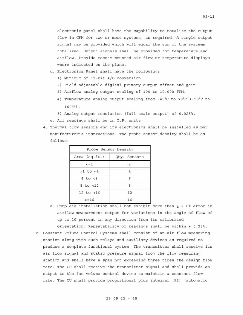
09-11
23 09 23 - 45
electronic panel shall have the capability to totalize the output
flow in CFM for two or more systems, as required. A single output
signal may be provided which will equal the sum of the systems
totalized. Output signals shall be provided for temperature and
airflow. Provide remote mounted air flow or temperature displays
where indicated on the plans.
d. Electronics Panel shall have the following:
1) Minimum of 12-bit A/D conversion.
2) Field adjustable digital primary output offset and gain.
3) Airflow analog output scaling of 100 to 10,000 FPM.
4) Temperature analog output scaling from -45°C to 70°C (-50°F to
160°F).
5) Analog output resolution (full scale output) of 0.025%.
e. All readings shall be in I.P. units.
4. Thermal flow sensors and its electronics shall be installed as per
manufacturer’s instructions. The probe sensor density shall be as
follows:
Probe Sensor Density
Area (sq.ft.) Qty. Sensors
<=1 2
>1 to <4 4
4 to <8 6
8 to <12 8
12 to <16 12
>=16 16
a. Complete installation shall not exhibit more than ± 2.0% error in
airflow measurement output for variations in the angle of flow of
up to 10 percent in any direction from its calibrated
orientation. Repeatability of readings shall be within ± 0.25%.
B. Constant Volume Control Systems shall consist of an air flow measuring
station along with such relays and auxiliary devices as required to
produce a complete functional system. The transmitter shall receive its
air flow signal and static pressure signal from the flow measuring
station and shall have a span not exceeding three times the design flow
rate. The CU shall receive the transmitter signal and shall provide an
output to the fan volume control device to maintain a constant flow
rate. The CU shall provide proportional plus integral (PI) (automatic
09-11
23 09 23 - 46
reset) control mode and where required also inverse derivative mode.
Overall system accuracy shall be plus or minus the equivalent of 2
Pascal (0.008 inch) velocity pressure as measured by the flow station.
PART 3 - EXECUTION
3.1 INSTALLATION
A. General:
1. Examine project plans for control devices and equipment locations;
and report any discrepancies, conflicts, or omissions to COR for
resolution before proceeding for installation.
2. Install equipment, piping, wiring /conduit parallel to or at right
angles to building lines.
3. Install all equipment and piping in readily accessible locations. Do
not run tubing and conduit concealed under insulation or inside
ducts.
4. Mount control devices, tubing and conduit located on ducts and
apparatus with external insulation on standoff support to avoid
interference with insulation.
5. Provide sufficient slack and flexible connections to allow for
vibration of piping and equipment.
6. Run tubing and wire connecting devices on or in control cabinets
parallel with the sides of the cabinet neatly racked to permit
tracing.
7. Install equipment level and plum.
A. Electrical Wiring Installation:
1. All wiring cabling shall be installed in conduits. Install conduits
and wiring in accordance with Specification Section 26 05 33,
RACEWAY AND BOXES FOR ELECTRICAL SYSTEMS. Conduits carrying control
wiring and cabling shall be dedicated to the control wiring and
cabling: these conduits shall not carry power wiring. Provide
plastic end sleeves at all conduit terminations to protect wiring
from burrs.
2. Install analog signal and communication cables in conduit and in
accordance with Specification Section 26 05 21. Install digital
communication cables in conduit and in accordance with Specification
Section 27 15 00, Communications Horizontal Cabling.
3. Install conduit and wiring between operator workstation(s), digital
controllers, electrical panels, indicating devices, instrumentation,
09-11
23 09 23 - 47
miscellaneous alarm points, thermostats, and relays as shown on the
drawings or as required under this section.
4. Install all electrical work required for a fully functional system
and not shown on electrical plans or required by electrical
specifications. Where low voltage (less than 50 volt) power is
required, provide suitable Class B transformers.
5. Install all system components in accordance with local Building Code
and National Electric Code.
a. Splices: Splices in shielded and coaxial cables shall consist of
terminations and the use of shielded cable couplers. Terminations
shall be in accessible locations. Cables shall be harnessed with
cable ties.
b. Equipment: Fit all equipment contained in cabinets or panels with
service loops, each loop being at least 300 mm (12 inches) long.
Equipment for fiber optics system shall be rack mounted, as
applicable, in ventilated, self-supporting, code gauge steel
enclosure. Cables shall be supported for minimum sag.
c. Cable Runs: Keep cable runs as short as possible. Allow extra
length for connecting to the terminal board. Do not bend flexible
coaxial cables in a radius less than ten times the cable outside
diameter.
d. Use vinyl tape, sleeves, or grommets to protect cables from
vibration at points where they pass around sharp corners, through
walls, panel cabinets, etc.
6. Conceal cables, except in mechanical rooms and areas where other
conduits and piping are exposed.
7. Permanently label or code each point of all field terminal strips to
show the instrument or item served. Color-coded cable with cable
diagrams may be used to accomplish cable identification.
8. Grounding: ground electrical systems per manufacturer’s written
requirements for proper and safe operation.
C. Install Sensors and Controls:
1. Temperature Sensors:
a. Install all sensors and instrumentation according to
manufacturer’s written instructions. Temperature sensor locations
shall be readily accessible, permitting quick replacement and
servicing of them without special skills and tools.
09-11
23 09 23 - 48
b. Calibrate sensors to accuracy specified, if not factory
calibrated.
c. Use of sensors shall be limited to its duty, e.g., duct sensor
shall not be used in lieu of room sensor.
d. Install room sensors permanently supported on wall frame. They
shall be mounted at 1.5 meter (5.0 feet) above the finished
floor.
e. Mount sensors rigidly and adequately for the environment within
which the sensor operates. Separate extended-bulb sensors form
contact with metal casings and coils using insulated standoffs.
f. Sensors used in mixing plenum, and hot and cold decks shall be of
the averaging of type. Averaging sensors shall be installed in a
serpentine manner horizontally across duct. Each bend shall be
supported with a capillary clip.
g. All pipe mounted temperature sensors shall be installed in wells.
h. All wires attached to sensors shall be air sealed in their
conduits or in the wall to stop air transmitted from other areas
affecting sensor reading.
i. Permanently mark terminal blocks for identification. Protect all
circuits to avoid interruption of service due to short-circuiting
or other conditions. Line-protect all wiring that comes from
external sources to the site from lightning and static
electricity.
2. Pressure Sensors:
a. Install duct static pressure sensor tips facing directly
downstream of airflow.
b. Install high-pressure side of the differential switch between the
pump discharge and the check valve.
c. Install snubbers and isolation valves on steam pressure sensing
devices.
3. Actuators:
a. Mount and link damper and valve actuators according to
manufacturer’s written instructions.
b. Check operation of damper/actuator combination to confirm that
actuator modulates damper smoothly throughout stroke to both open
and closed position.
09-11
23 09 23 - 49
c. Check operation of valve/actuator combination to confirm that
actuator modulates valve smoothly in both open and closed
position.
4. Flow Switches:
a. Install flow switch according to manufacturer’s written
instructions.
b. Mount flow switch a minimum of 5 pipe diameters up stream and 5
pipe diameters downstream or 600 mm (2 feet) whichever is
greater, from fittings and other obstructions.
c. Assure correct flow direction and alignment.
d. Mount in horizontal piping-flow switch on top of the pipe.
D. Installation of network:
1. Ethernet:
a. The network shall employ Ethernet LAN architecture, as defined by
IEEE 802.3. The Network Interface shall be fully Internet
Protocol (IP) compliant allowing connection to currently
installed IEEE 802.3, Compliant Ethernet Networks.
b. The network shall directly support connectivity to a variety of
cabling types. As a minimum provide the following connectivity:
100 Base TX (Category 5e cabling) for the communications between
the ECC and the B-BC and the B-AAC controllers.
2. Third party interfaces: Contractor shall integrate real-time data
from building systems by other trades and databases originating from
other manufacturers as specified and required to make the system
work as one system.
E. Installation of digital controllers and programming:
1. Provide a separate digital control panel for each major piece of
equipment, such as air handling unit, chiller, pumping unit etc.
Points used for control loop reset such as outdoor air, outdoor
humidity, or space temperature could be located on any of the remote
control units.
2. Provide sufficient internal memory for the specified control
sequences and trend logging. There shall be a minimum of 25 percent
of available memory free for future use.
3. System point names shall be modular in design, permitting easy
operator interface without the use of a written point index.
4. Provide software programming for the applications intended for the
systems specified, and adhere to the strategy algorithms provided.
09-11
23 09 23 - 50
5. Provide graphics for each piece of equipment and floor plan in the
building. This includes each chiller, cooling tower, air handling
unit, fan, terminal unit, boiler, pumping unit etc. These graphics
shall show all points dynamically as specified in the point list.
3.2 SYSTEM VALIDATION AND DEMONSTRATION
A. As part of final system acceptance, a system demonstration is required
(see below). Prior to start of this demonstration, the Contractor is
to perform a complete validation of all aspects of the controls and
instrumentation system.
B. Validation
1. Prepare and submit for approval a validation test plan including
test procedures for the performance verification tests. Test Plan
shall address all specified functions of the ECC and all specified
sequences of operation. Explain in detail actions and expected
results used to demonstrate compliance with the requirements of this
specification. Explain the method for simulating the necessary
conditions of operation used to demonstrate performance of the
system. Test plan shall include a test check list to be used by the
Installer’s agent to check and initial that each test has been
successfully completed. Deliver test plan documentation for the
performance verification tests to the owner’s representative 30 days
prior to start of performance verification tests. Provide draft
copy of operation and maintenance manual with performance
verification test.
2. After approval of the validation test plan, installer shall carry
out all tests and procedures therein. Installer shall completely
check out, calibrate, and test all connected hardware and software
to insure that system performs in accordance with approved
specifications and sequences of operation submitted. Installer
shall complete and submit Test Check List.
C. Demonstration
1. System operation and calibration to be demonstrated by the installer
in the presence of the Architect or VA's representative on random
samples of equipment as dictated by the Architect or VA’s
representative. Should random sampling indicate improper
commissioning, the owner reserves the right to subsequently witness
complete calibration of the system at no addition cost to the VA.
09-11
23 09 23 - 51
2. Demonstrate to authorities that all required safeties and life
safety functions are fully functional and complete.
3. Make accessible, personnel to provide necessary adjustments and
corrections to systems as directed by balancing agency.
4. The following witnessed demonstrations of field control equipment
shall be included:
a. Observe HVAC systems in shut down condition. Check dampers and
valves for normal position.
b. Test application software for its ability to communicate with
digital controllers, operator workstation, and uploading and
downloading of control programs.
c. Demonstrate the software ability to edit the control program off-
line.
d. Demonstrate reporting of alarm conditions for each alarm and
ensure that these alarms are received at the assigned location,
including operator workstations.
e. Demonstrate ability of software program to function for the
intended applications-trend reports, change in status etc.
f. Demonstrate via graphed trends to show the sequence of operation
is executed in correct manner, and that the HVAC systems operate
properly through the complete sequence of operation, e.g.,
seasonal change, occupied/unoccupied mode, and warm-up condition.
g. Demonstrate hardware interlocks and safeties functions, and that
the control systems perform the correct sequence of operation
after power loss and resumption of power loss.
h. Prepare and deliver to the VA graphed trends of all control loops
to demonstrate that each control loop is stable and the set
points are maintained.
i. Demonstrate that each control loop responds to set point
adjustment and stabilizes within one (1) minute. Control loop
trend data shall be instantaneous and the time between data
points shall not be greater than one (1) minute.
5. Witnessed demonstration of ECC functions shall consist of:
a. Running each specified report.
b. Display and demonstrate each data entry to show site specific
customizing capability. Demonstrate parameter changes.
c. Step through penetration tree, display all graphics, demonstrate
dynamic update, and direct access to graphics.

09-11
23 09 23 - 52
d. Execute digital and analog commands in graphic mode.
e. Demonstrate DDC loop precision and stability via trend logs of
inputs and outputs (6 loops minimum).
f. Demonstrate EMS performance via trend logs and command trace.
g. Demonstrate scan, update, and alarm responsiveness.
h. Demonstrate spreadsheet/curve plot software, and its integration
with database.
i. Demonstrate on-line user guide, and help function and mail
facility.
j. Demonstrate digital system configuration graphics with
interactive upline and downline load, and demonstrate specified
diagnostics.
k. Demonstrate multitasking by showing dynamic curve plot, and
graphic construction operating simultaneously via split screen.
l. Demonstrate class programming with point options of beep
duration, beep rate, alarm archiving, and color banding.
3.3 Decommissioning of Existing Alerton ECC.
A. Upon full integration of existing Alerton ECC with the existing
Tridium system, and verification of operation of local control
components are equal to that prior to start of work, the existing
Alerton ECC shall decommissioned and removed.
----- END -----

Thursday, January 03, 2013
Name: Alerton BACtalk Server Instance: 10000 Description: Alerton BACtalk ServerModel: Envision for BACtalk Network: 1 MAC Addr:
Device Summary
Location: Bldg-1 Grnd Flr B Wing Rep Dir: Job Dir:
Name: Alerton WEBtalk Server Instance: 10001 Description: Alerton WEBtalk ServerModel: WEBtalk Network: 1 MAC Addr: 0xc0a80501bac0
Location: Bldg-1 Grnd Flr B Wing Rep Dir: Job Dir:
Name: 1B-G-BCM-ETH Instance: 10100 Description: 1B-G-BCM-ETHModel: BCM Eth Controller Network: 0 MAC Addr: 0xc0a80509bac0Model: BCM-Eth Controller Network: 0 MAC Addr: 0xc0a80509bac0
Location: Bldg-1 Grnd Flr RM-B111a Rep Dir: MBS Job Dir: VA
Name: 1B-1-RHT/FNC VLC-1 Instance: 10101 Description: 1B-1-RHT/FNC VLC-1Model: VLC-1188 Network: 101 MAC Addr: 1
Location: Rep Dir: MBS Job Dir: VA
Name: 1B-1-RHT/FNC VLC-2 Instance: 10102 Description: 1B-1-RHT/FNC VLC-2Model: VAV-SD2A Network: 101 MAC Addr: 2
Location: Rep Dir: MBS Job Dir: VA
Name: 1B-1-RHT/FNC VLC-3 Instance: 10103 Description: 1B-1-RHT/FNC VLC-3Model: VAV-SD2A Network: 101 MAC Addr: 3
Location: Rep Dir: MBS Job Dir: VA
1B 1 RHT/FNC VLC 15 10104 i i 1B 1 RHT/FNC VLC 15Name: 1B-1-RHT/FNC VLC-15 Instance: 10104 Description: 1B-1-RHT/FNC VLC-15Model: VLC-1188 Network: 101 MAC Addr: 4
Location: Storage Room Rep Dir: Job Dir:
Name: 1B-G-AC-106 VLC-1 Instance: 10160 Description: 1B-G-AC-106 VLC-1Model: VLC-1188 Network: 101 MAC Addr: 60
Location: Rep Dir: MBS Job Dir: VA
Name: 1B-G-AC-106 VLC-2 Instance: 10161 Description: 1B-G-AC-106 VLC-2Model: VLC-1188 Network: 101 MAC Addr: 61
Location: Rep Dir: MBS Job Dir: VA
Name: 1B-G-AC-106 Mech Rm HV Control Instance: 10162 Description: 1B-G-AC-106 Mech Rm HV ControlModel: VAV-SD2A Network: 101 MAC Addr: 62
Location: 1B-G-AC-106 Panel Rep Dir: MBS Job Dir: VA
Name: 1B-G-AC-148 VLC-1 Instance: 10163 Description: 1B-G-AC-148 VLC-1Model: VLC-1188 Network: 101 MAC Addr: 63
Location: Mechanical Room B-302 Rep Dir: MBS Job Dir: VA
Name: 1B-G-AC-148 VLC-2 Instance: 10164 Description: 1B-G-AC-148 VLC-2Model: VLC-1188 Network: 101 MAC Addr: 64
Location: Mechanical Room B-302 Rep Dir: MBS Job Dir: VALocation: Mechanical Room B-302 Rep Dir: MBS Job Dir: VA
Page 1 of 18
Specification Section 23 09 23 - Attachment A
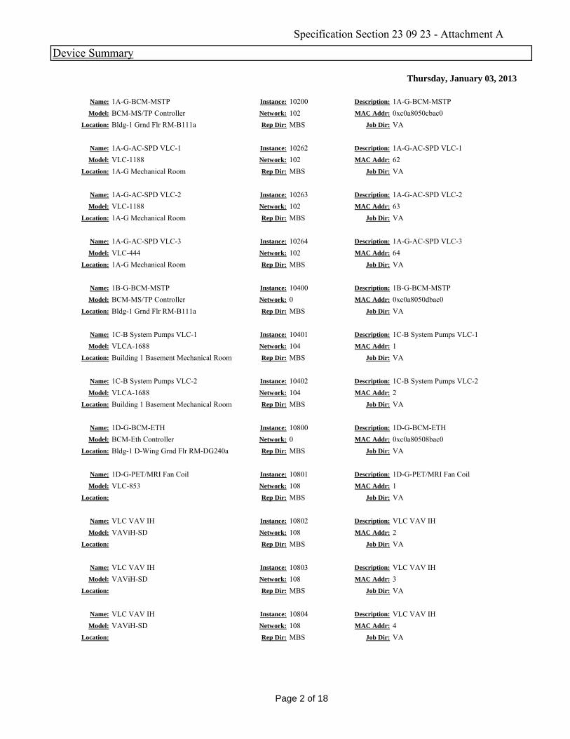
Thursday, January 03, 2013
Device Summary
Name: 1A-G-BCM-MSTP Instance: 10200 Description: 1A-G-BCM-MSTPModel: BCM-MS/TP Controller Network: 102 MAC Addr: 0xc0a8050cbac0
Location: Bldg-1 Grnd Flr RM-B111a Rep Dir: MBS Job Dir: VA
Name: 1A-G-AC-SPD VLC-1 Instance: 10262 Description: 1A-G-AC-SPD VLC-1Model: VLC-1188 Network: 102 MAC Addr: 62
Location: 1A-G Mechanical Room Rep Dir: MBS Job Dir: VA
Name: 1A-G-AC-SPD VLC-2 Instance: 10263 Description: 1A-G-AC-SPD VLC-2Model: VLC 1188 Network: 102 MAC Addr: 63Model: VLC-1188 Network: 102 MAC Addr: 63
Location: 1A-G Mechanical Room Rep Dir: MBS Job Dir: VA
Name: 1A-G-AC-SPD VLC-3 Instance: 10264 Description: 1A-G-AC-SPD VLC-3Model: VLC-444 Network: 102 MAC Addr: 64
Location: 1A-G Mechanical Room Rep Dir: MBS Job Dir: VA
Name: 1B-G-BCM-MSTP Instance: 10400 Description: 1B-G-BCM-MSTPModel: BCM-MS/TP Controller Network: 0 MAC Addr: 0xc0a8050dbac0
Location: Bldg-1 Grnd Flr RM-B111a Rep Dir: MBS Job Dir: VA
Name: 1C-B System Pumps VLC-1 Instance: 10401 Description: 1C-B System Pumps VLC-1Model: VLCA-1688 Network: 104 MAC Addr: 1
Location: Building 1 Basement Mechanical Room Rep Dir: MBS Job Dir: VA
1C B S P VLC 2 10402 i i 1C B S P VLC 2Name: 1C-B System Pumps VLC-2 Instance: 10402 Description: 1C-B System Pumps VLC-2Model: VLCA-1688 Network: 104 MAC Addr: 2
Location: Building 1 Basement Mechanical Room Rep Dir: MBS Job Dir: VA
Name: 1D-G-BCM-ETH Instance: 10800 Description: 1D-G-BCM-ETHModel: BCM-Eth Controller Network: 0 MAC Addr: 0xc0a80508bac0
Location: Bldg-1 D-Wing Grnd Flr RM-DG240a Rep Dir: MBS Job Dir: VA
Name: 1D-G-PET/MRI Fan Coil Instance: 10801 Description: 1D-G-PET/MRI Fan CoilModel: VLC-853 Network: 108 MAC Addr: 1
Location: Rep Dir: MBS Job Dir: VA
Name: VLC VAV IH Instance: 10802 Description: VLC VAV IHModel: VAViH-SD Network: 108 MAC Addr: 2
Location: Rep Dir: MBS Job Dir: VA
Name: VLC VAV IH Instance: 10803 Description: VLC VAV IHModel: VAViH-SD Network: 108 MAC Addr: 3
Location: Rep Dir: MBS Job Dir: VA
Name: VLC VAV IH Instance: 10804 Description: VLC VAV IHModel: VAViH-SD Network: 108 MAC Addr: 4
Location: Rep Dir: MBS Job Dir: VALocation: Rep Dir: MBS Job Dir: VA
Page 2 of 18
Specification Section 23 09 23 - Attachment A

Thursday, January 03, 2013
Device Summary
Name: VLC VAV IH Instance: 10805 Description: VLC VAV IHModel: VAViH-SD Network: 108 MAC Addr: 5
Location: Rep Dir: MBS Job Dir: VA
Name: Instance: 10806 Description:
Model: VAV-SD2A Network: 108 MAC Addr: 6Location: Rep Dir: MBS Job Dir: VA
Name: 1D-B2-BCM-ETH Instance: 10900 Description: 1D-B2-BCM-ETHModel: BCM Eth Controller Network: 0 MAC Addr: 0xc0a8050fbac0Model: BCM-Eth Controller Network: 0 MAC Addr: 0xc0a8050fbac0
Location: Rep Dir: MBS Job Dir: VA
Name: Dev-10907 Instance: 10907 Description: Rm DB2-2240Model: VAViH-SD Network: 109 MAC Addr: 7
Location: Ceiling DB2-2240 Rep Dir: MBS Job Dir: VA
Name: Dev-10908 Instance: 10908 Description: Rm DB2-222Model: VAViH-SD Network: 109 MAC Addr: 8
Location: Ceiling DB2-222 Rep Dir: MBS Job Dir: VA
Name: Dev-10910 Instance: 10909 Description: Rm DB2-223Model: VAViH-SD Network: 109 MAC Addr: 9
Location: Rm DB2-223 Rep Dir: MBS Job Dir: VA
D 10910 10910 i i R DB2 224 225Name: Dev-10910 Instance: 10910 Description: Rm DB2-224,225Model: VAViH-SD Network: 109 MAC Addr: 10
Location: Ceiling DB2-224,225 Rep Dir: MBS Job Dir: VA
Name: Dev-10911 Instance: 10911 Description: Rm DB2-2228Model: VAViH-SD Network: 109 MAC Addr: 11
Location: Ceiling DB2-2228 Rep Dir: MBS Job Dir: VA
Name: Dev-10912 Instance: 10912 Description: Rm DB2-237Model: VAViH-SD Network: 109 MAC Addr: 12
Location: Ceiling DB2-237 Rep Dir: MBS Job Dir: VA
Name: Dev-10913 Instance: 10913 Description: Rm DB2-236Model: VAViH-SD Network: 109 MAC Addr: 13
Location: Ceiling DB2-236 Rep Dir: MBS Job Dir: VA
Name: Dev-10914 Instance: 10914 Description: Rm DB2-234Model: VAViH-SD Network: 109 MAC Addr: 14
Location: Ceiling DB2-234 Rep Dir: MBS Job Dir: VA
Name: Dev-10915 Instance: 10915 Description: Rm DB2-233Model: VAViH-SD Network: 109 MAC Addr: 15
Location: Ceiling DB2-233 Rep Dir: MBS Job Dir: VALocation: Ceiling DB2-233 Rep Dir: MBS Job Dir: VA
Page 3 of 18
Specification Section 23 09 23 - Attachment A

Thursday, January 03, 2013
Device Summary
Name: Dev-10916 Instance: 10916 Description: Rm DB2-227Model: VAViH-SD Network: 109 MAC Addr: 16
Location: Ceiling DB2-227 Rep Dir: MBS Job Dir: VA
Name: Dev-10917 Instance: 10917 Description: Rm DB2-226Model: VAViH-SD Network: 109 MAC Addr: 17
Location: Ceiling DB2-226 Rep Dir: MBS Job Dir: VA
Name: VLC VAV IH Instance: 10918 Description: VLC VAV IHModel: VAViH SD Network: 109 MAC Addr: 18Model: VAViH-SD Network: 109 MAC Addr: 18
Location: Rep Dir: Job Dir:
Name: VLC VAV IH Instance: 10919 Description: VLC VAV IHModel: VAViH-SD Network: 109 MAC Addr: 19
Location: Rep Dir: Job Dir:
Name: VLC VAV IH Instance: 10920 Description: VLC VAV IHModel: VAViH-SD Network: 109 MAC Addr: 20
Location: Rep Dir: Job Dir:
Name: VLC VAV IH Instance: 10921 Description: VLC VAV IHModel: VAViH-SD Network: 109 MAC Addr: 21
Location: Rep Dir: Job Dir:
VLC VAV IH 10922 i i VLC VAV IHName: VLC VAV IH Instance: 10922 Description: VLC VAV IHModel: VAViH-SD Network: 109 MAC Addr: 22
Location: Rep Dir: Job Dir:
Name: VLC VAV IH Instance: 10923 Description: VLC VAV IHModel: VAViH-SD Network: 109 MAC Addr: 23
Location: Rep Dir: Job Dir:
Name: Dev-10927 Instance: 10927 Description: Rm DB2-232Model: VAViH-SD Network: 109 MAC Addr: 27
Location: Ceiling DB2-232 Rep Dir: MBS Job Dir: VA
Name: Dev-10928 Instance: 10928 Description: Rm DB2-2236,256,257Model: VAViH-SD Network: 109 MAC Addr: 28
Location: Ceiling DB2-2236 Rep Dir: MBS Job Dir: VA
Name: Dev-10929 Instance: 10929 Description: Rm DB2-258,259,260Model: VAViH-SD Network: 109 MAC Addr: 29
Location: Ceiling DB2-258 Rep Dir: MBS Job Dir: VA
Name: Dev-10930 Instance: 10930 Description: Rm DB2-258Model: VAViH-SD Network: 109 MAC Addr: 30
Location: Ceiling DB2-258 Rep Dir: MBS Job Dir: VALocation: Ceiling DB2-258 Rep Dir: MBS Job Dir: VA
Page 4 of 18
Specification Section 23 09 23 - Attachment A
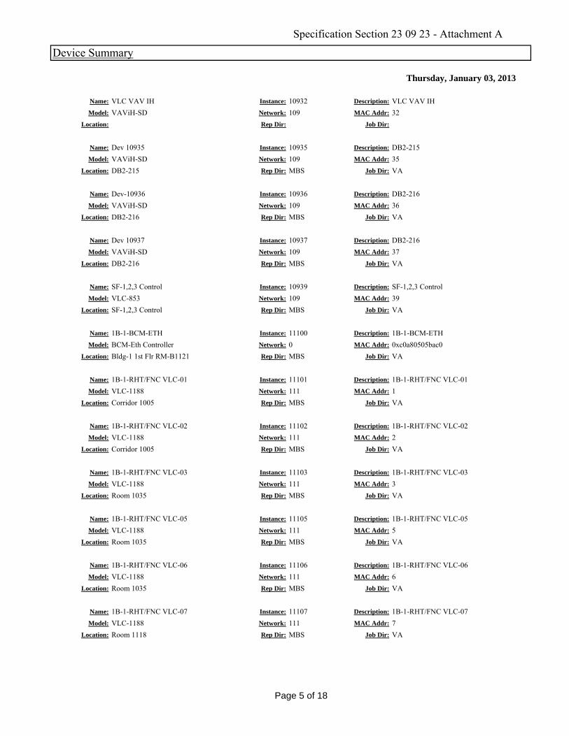
Thursday, January 03, 2013
Device Summary
Name: VLC VAV IH Instance: 10932 Description: VLC VAV IHModel: VAViH-SD Network: 109 MAC Addr: 32
Location: Rep Dir: Job Dir:
Name: Dev 10935 Instance: 10935 Description: DB2-215Model: VAViH-SD Network: 109 MAC Addr: 35
Location: DB2-215 Rep Dir: MBS Job Dir: VA
Name: Dev-10936 Instance: 10936 Description: DB2-216Model: VAViH SD Network: 109 MAC Addr: 36Model: VAViH-SD Network: 109 MAC Addr: 36
Location: DB2-216 Rep Dir: MBS Job Dir: VA
Name: Dev 10937 Instance: 10937 Description: DB2-216Model: VAViH-SD Network: 109 MAC Addr: 37
Location: DB2-216 Rep Dir: MBS Job Dir: VA
Name: SF-1,2,3 Control Instance: 10939 Description: SF-1,2,3 ControlModel: VLC-853 Network: 109 MAC Addr: 39
Location: SF-1,2,3 Control Rep Dir: MBS Job Dir: VA
Name: 1B-1-BCM-ETH Instance: 11100 Description: 1B-1-BCM-ETHModel: BCM-Eth Controller Network: 0 MAC Addr: 0xc0a80505bac0
Location: Bldg-1 1st Flr RM-B1121 Rep Dir: MBS Job Dir: VA
1B 1 RHT/FNC VLC 01 11101 i i 1B 1 RHT/FNC VLC 01Name: 1B-1-RHT/FNC VLC-01 Instance: 11101 Description: 1B-1-RHT/FNC VLC-01Model: VLC-1188 Network: 111 MAC Addr: 1
Location: Corridor 1005 Rep Dir: MBS Job Dir: VA
Name: 1B-1-RHT/FNC VLC-02 Instance: 11102 Description: 1B-1-RHT/FNC VLC-02Model: VLC-1188 Network: 111 MAC Addr: 2
Location: Corridor 1005 Rep Dir: MBS Job Dir: VA
Name: 1B-1-RHT/FNC VLC-03 Instance: 11103 Description: 1B-1-RHT/FNC VLC-03Model: VLC-1188 Network: 111 MAC Addr: 3
Location: Room 1035 Rep Dir: MBS Job Dir: VA
Name: 1B-1-RHT/FNC VLC-05 Instance: 11105 Description: 1B-1-RHT/FNC VLC-05Model: VLC-1188 Network: 111 MAC Addr: 5
Location: Room 1035 Rep Dir: MBS Job Dir: VA
Name: 1B-1-RHT/FNC VLC-06 Instance: 11106 Description: 1B-1-RHT/FNC VLC-06Model: VLC-1188 Network: 111 MAC Addr: 6
Location: Room 1035 Rep Dir: MBS Job Dir: VA
Name: 1B-1-RHT/FNC VLC-07 Instance: 11107 Description: 1B-1-RHT/FNC VLC-07Model: VLC-1188 Network: 111 MAC Addr: 7
Location: Room 1118 Rep Dir: MBS Job Dir: VALocation: Room 1118 Rep Dir: MBS Job Dir: VA
Page 5 of 18
Specification Section 23 09 23 - Attachment A

Thursday, January 03, 2013
Device Summary
Name: 1B-1-RHT/FNC VLC-08 Instance: 11108 Description: 1B-1-RHT/FNC VLC-08Model: VLC-1188 Network: 111 MAC Addr: 8
Location: Room 1118 Rep Dir: MBS Job Dir: VA
Name: 1B-1-RHT/FNC VLC-09 Instance: 11109 Description: 1B-1-RHT/FNC VLC-09Model: VLC-1188 Network: 111 MAC Addr: 9
Location: Room 1017 Rep Dir: MBS Job Dir: VA
Name: 1B-1-RHT/FNC VLC-10 Instance: 11110 Description: 1B-1-RHT/FNC VLC-10Model: VLC 1188 Network: 111 MAC Addr: 10Model: VLC-1188 Network: 111 MAC Addr: 10
Location: Room 1017 Rep Dir: MBS Job Dir: VA
Name: 1B-1-RHT/FNC VLC-11 Instance: 11111 Description: 1B-1-RHT/FNC VLC-11Model: VLC-1188 Network: 111 MAC Addr: 11
Location: Room 1070 Rep Dir: MBS Job Dir: VA
Name: 1B-1-RHT/FNC VLC-12 Instance: 11112 Description: 1B-1-RHT/FNC VLC-12Model: VLC-1188 Network: 111 MAC Addr: 12
Location: Room 1070 Rep Dir: MBS Job Dir: VA
Name: 1B-1-RHT/FNC VLC-13 Instance: 11113 Description: 1B-1-RHT/FNC VLC-13Model: VLC-1188 Network: 111 MAC Addr: 13
Location: Room 1017 Rep Dir: MBS Job Dir: VA
1B 1 RHT/FNC VLC 14 11114 i i 1B 1 RHT/FNC VLC 14Name: 1B-1-RHT/FNC VLC-14 Instance: 11114 Description: 1B-1-RHT/FNC VLC-14Model: VLC-1188 Network: 111 MAC Addr: 14
Location: Room 1070 Rep Dir: MBS Job Dir: VA
Name: 1D-2-BCM-ETH Instance: 12100 Description: 1D-2-BCM-ETHModel: BCM-Eth Controller Network: 121 MAC Addr: 0xc0a8050ebac0
Location: Building 1 2nd Floor Data Closet Rep Dir: MBS Job Dir: VA
Name: 1D-2 System Pumps VLCA-1 Instance: 12101 Description: 1D-2 System Pumps VLCA-1Model: VLCA-1688 Network: 121 MAC Addr: 1
Location: Building 1D 2nd floor Mechanical Room Rep Dir: MBS Job Dir: VA
Name: 1C-4-BCM-ETH Instance: 14100 Description: 1C-4-BCM-ETHModel: BCM-Eth Controller Network: 0 MAC Addr: 0xc0a8050bbac0
Location: Bldg-1 4th Flr RM-4110a Rep Dir: MBS Job Dir: VA
Name: 1C-5-BCM-ETH Instance: 15100 Description: 1C-5-BCM-ETHModel: BCM-Eth Controller Network: 1 MAC Addr:
Location: 5th flr Penthouse Rep Dir: MBS Job Dir: VA
Name: 1C-4-BC01 VLC-1 Instance: 15101 Description: 1C-4-BC01 VLC-1Model: VAV-SD Network: 151 MAC Addr: 1
Location: 5C Mechanical Room Rep Dir: MBS Job Dir: VALocation: 5C Mechanical Room Rep Dir: MBS Job Dir: VA
Page 6 of 18
Specification Section 23 09 23 - Attachment A
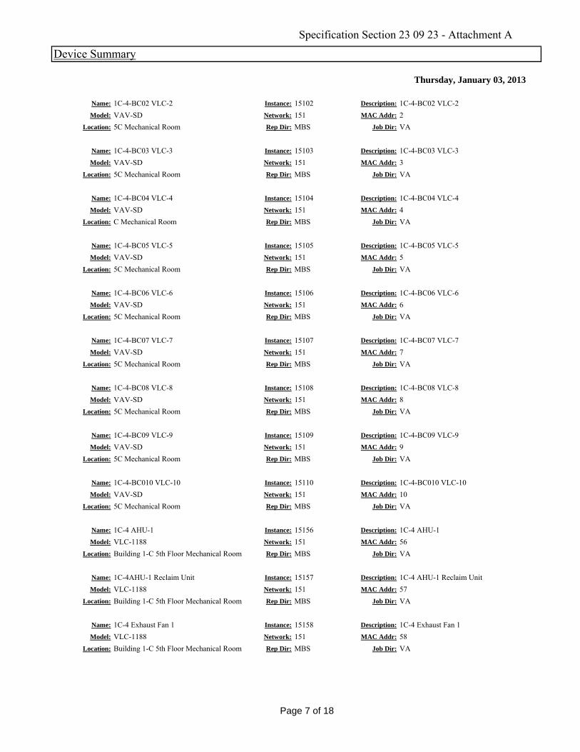
Thursday, January 03, 2013
Device Summary
Name: 1C-4-BC02 VLC-2 Instance: 15102 Description: 1C-4-BC02 VLC-2Model: VAV-SD Network: 151 MAC Addr: 2
Location: 5C Mechanical Room Rep Dir: MBS Job Dir: VA
Name: 1C-4-BC03 VLC-3 Instance: 15103 Description: 1C-4-BC03 VLC-3Model: VAV-SD Network: 151 MAC Addr: 3
Location: 5C Mechanical Room Rep Dir: MBS Job Dir: VA
Name: 1C-4-BC04 VLC-4 Instance: 15104 Description: 1C-4-BC04 VLC-4Model: VAV SD Network: 151 MAC Addr: 4Model: VAV-SD Network: 151 MAC Addr: 4
Location: C Mechanical Room Rep Dir: MBS Job Dir: VA
Name: 1C-4-BC05 VLC-5 Instance: 15105 Description: 1C-4-BC05 VLC-5Model: VAV-SD Network: 151 MAC Addr: 5
Location: 5C Mechanical Room Rep Dir: MBS Job Dir: VA
Name: 1C-4-BC06 VLC-6 Instance: 15106 Description: 1C-4-BC06 VLC-6Model: VAV-SD Network: 151 MAC Addr: 6
Location: 5C Mechanical Room Rep Dir: MBS Job Dir: VA
Name: 1C-4-BC07 VLC-7 Instance: 15107 Description: 1C-4-BC07 VLC-7Model: VAV-SD Network: 151 MAC Addr: 7
Location: 5C Mechanical Room Rep Dir: MBS Job Dir: VA
1C 4 BC08 VLC 8 15108 i i 1C 4 BC08 VLC 8Name: 1C-4-BC08 VLC-8 Instance: 15108 Description: 1C-4-BC08 VLC-8Model: VAV-SD Network: 151 MAC Addr: 8
Location: 5C Mechanical Room Rep Dir: MBS Job Dir: VA
Name: 1C-4-BC09 VLC-9 Instance: 15109 Description: 1C-4-BC09 VLC-9Model: VAV-SD Network: 151 MAC Addr: 9
Location: 5C Mechanical Room Rep Dir: MBS Job Dir: VA
Name: 1C-4-BC010 VLC-10 Instance: 15110 Description: 1C-4-BC010 VLC-10Model: VAV-SD Network: 151 MAC Addr: 10
Location: 5C Mechanical Room Rep Dir: MBS Job Dir: VA
Name: 1C-4 AHU-1 Instance: 15156 Description: 1C-4 AHU-1Model: VLC-1188 Network: 151 MAC Addr: 56
Location: Building 1-C 5th Floor Mechanical Room Rep Dir: MBS Job Dir: VA
Name: 1C-4AHU-1 Reclaim Unit Instance: 15157 Description: 1C-4 AHU-1 Reclaim UnitModel: VLC-1188 Network: 151 MAC Addr: 57
Location: Building 1-C 5th Floor Mechanical Room Rep Dir: MBS Job Dir: VA
Name: 1C-4 Exhaust Fan 1 Instance: 15158 Description: 1C-4 Exhaust Fan 1Model: VLC-1188 Network: 151 MAC Addr: 58
Location: Building 1-C 5th Floor Mechanical Room Rep Dir: MBS Job Dir: VALocation: Building 1-C 5th Floor Mechanical Room Rep Dir: MBS Job Dir: VA
Page 7 of 18
Specification Section 23 09 23 - Attachment A
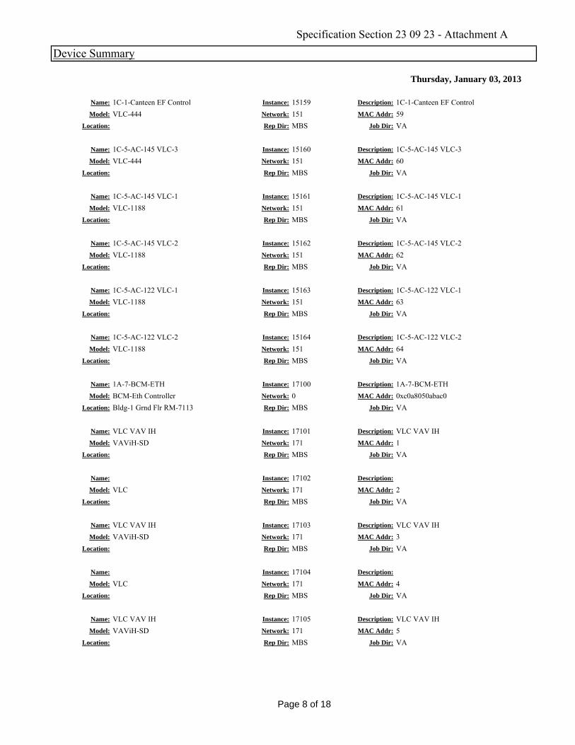
Thursday, January 03, 2013
Device Summary
Name: 1C-1-Canteen EF Control Instance: 15159 Description: 1C-1-Canteen EF ControlModel: VLC-444 Network: 151 MAC Addr: 59
Location: Rep Dir: MBS Job Dir: VA
Name: 1C-5-AC-145 VLC-3 Instance: 15160 Description: 1C-5-AC-145 VLC-3Model: VLC-444 Network: 151 MAC Addr: 60
Location: Rep Dir: MBS Job Dir: VA
Name: 1C-5-AC-145 VLC-1 Instance: 15161 Description: 1C-5-AC-145 VLC-1Model: VLC 1188 Network: 151 MAC Addr: 61Model: VLC-1188 Network: 151 MAC Addr: 61
Location: Rep Dir: MBS Job Dir: VA
Name: 1C-5-AC-145 VLC-2 Instance: 15162 Description: 1C-5-AC-145 VLC-2Model: VLC-1188 Network: 151 MAC Addr: 62
Location: Rep Dir: MBS Job Dir: VA
Name: 1C-5-AC-122 VLC-1 Instance: 15163 Description: 1C-5-AC-122 VLC-1Model: VLC-1188 Network: 151 MAC Addr: 63
Location: Rep Dir: MBS Job Dir: VA
Name: 1C-5-AC-122 VLC-2 Instance: 15164 Description: 1C-5-AC-122 VLC-2Model: VLC-1188 Network: 151 MAC Addr: 64
Location: Rep Dir: MBS Job Dir: VA
1A 7 BCM ETH 17100 i i 1A 7 BCM ETHName: 1A-7-BCM-ETH Instance: 17100 Description: 1A-7-BCM-ETHModel: BCM-Eth Controller Network: 0 MAC Addr: 0xc0a8050abac0
Location: Bldg-1 Grnd Flr RM-7113 Rep Dir: MBS Job Dir: VA
Name: VLC VAV IH Instance: 17101 Description: VLC VAV IHModel: VAViH-SD Network: 171 MAC Addr: 1
Location: Rep Dir: MBS Job Dir: VA
Name: Instance: 17102 Description:
Model: VLC Network: 171 MAC Addr: 2Location: Rep Dir: MBS Job Dir: VA
Name: VLC VAV IH Instance: 17103 Description: VLC VAV IHModel: VAViH-SD Network: 171 MAC Addr: 3
Location: Rep Dir: MBS Job Dir: VA
Name: Instance: 17104 Description:
Model: VLC Network: 171 MAC Addr: 4Location: Rep Dir: MBS Job Dir: VA
Name: VLC VAV IH Instance: 17105 Description: VLC VAV IHModel: VAViH-SD Network: 171 MAC Addr: 5
Location: Rep Dir: MBS Job Dir: VALocation: Rep Dir: MBS Job Dir: VA
Page 8 of 18
Specification Section 23 09 23 - Attachment A
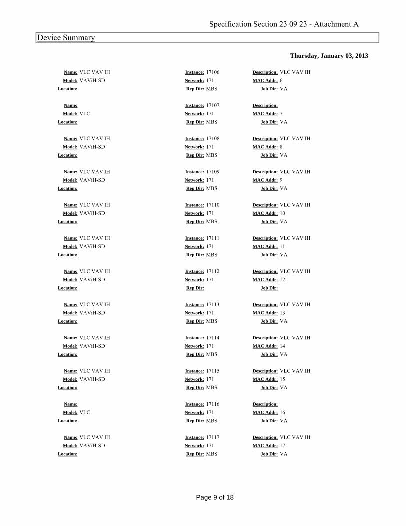
Thursday, January 03, 2013
Device Summary
Name: VLC VAV IH Instance: 17106 Description: VLC VAV IHModel: VAViH-SD Network: 171 MAC Addr: 6
Location: Rep Dir: MBS Job Dir: VA
Name: Instance: 17107 Description:
Model: VLC Network: 171 MAC Addr: 7Location: Rep Dir: MBS Job Dir: VA
Name: VLC VAV IH Instance: 17108 Description: VLC VAV IHModel: VAViH SD Network: 171 MAC Addr: 8Model: VAViH-SD Network: 171 MAC Addr: 8
Location: Rep Dir: MBS Job Dir: VA
Name: VLC VAV IH Instance: 17109 Description: VLC VAV IHModel: VAViH-SD Network: 171 MAC Addr: 9
Location: Rep Dir: MBS Job Dir: VA
Name: VLC VAV IH Instance: 17110 Description: VLC VAV IHModel: VAViH-SD Network: 171 MAC Addr: 10
Location: Rep Dir: MBS Job Dir: VA
Name: VLC VAV IH Instance: 17111 Description: VLC VAV IHModel: VAViH-SD Network: 171 MAC Addr: 11
Location: Rep Dir: MBS Job Dir: VA
VLC VAV IH 17112 i i VLC VAV IHName: VLC VAV IH Instance: 17112 Description: VLC VAV IHModel: VAViH-SD Network: 171 MAC Addr: 12
Location: Rep Dir: Job Dir:
Name: VLC VAV IH Instance: 17113 Description: VLC VAV IHModel: VAViH-SD Network: 171 MAC Addr: 13
Location: Rep Dir: MBS Job Dir: VA
Name: VLC VAV IH Instance: 17114 Description: VLC VAV IHModel: VAViH-SD Network: 171 MAC Addr: 14
Location: Rep Dir: MBS Job Dir: VA
Name: VLC VAV IH Instance: 17115 Description: VLC VAV IHModel: VAViH-SD Network: 171 MAC Addr: 15
Location: Rep Dir: MBS Job Dir: VA
Name: Instance: 17116 Description:
Model: VLC Network: 171 MAC Addr: 16Location: Rep Dir: MBS Job Dir: VA
Name: VLC VAV IH Instance: 17117 Description: VLC VAV IHModel: VAViH-SD Network: 171 MAC Addr: 17
Location: Rep Dir: MBS Job Dir: VALocation: Rep Dir: MBS Job Dir: VA
Page 9 of 18
Specification Section 23 09 23 - Attachment A

Thursday, January 03, 2013
Device Summary
Name: VLC VAV IH Instance: 17118 Description: VLC VAV IHModel: VAViH-SD Network: 171 MAC Addr: 18
Location: Rep Dir: Job Dir:
Name: VLC VAV IH Instance: 17119 Description: VLC VAV IHModel: VAViH-SD Network: 171 MAC Addr: 19
Location: Rep Dir: MBS Job Dir: VA
Name: VLC VAV IH Instance: 17120 Description: VLC VAV IHModel: VAViH SD Network: 171 MAC Addr: 20Model: VAViH-SD Network: 171 MAC Addr: 20
Location: Rep Dir: MBS Job Dir: VA
Name: Instance: 17121 Description:
Model: VLC Network: 171 MAC Addr: 21Location: Rep Dir: MBS Job Dir: VA
Name: VLC VAV IH Instance: 17122 Description: VLC VAV IHModel: VAViH-SD Network: 171 MAC Addr: 22
Location: Rep Dir: MBS Job Dir: VA
Name: VLC VAV IH Instance: 17123 Description: VLC VAV IHModel: VAViH-SD Network: 171 MAC Addr: 23
Location: Rep Dir: MBS Job Dir: VA
VLC VAV IH 17124 i i VLC VAV IHName: VLC VAV IH Instance: 17124 Description: VLC VAV IHModel: VAViH-SD Network: 171 MAC Addr: 24
Location: Rep Dir: MBS Job Dir: VA
Name: VLC VAV IH Instance: 17125 Description: VLC VAV IHModel: VAViH-SD Network: 171 MAC Addr: 25
Location: Rep Dir: MBS Job Dir: VA
Name: 1-8-D Morgue Exhaust Fan Control Instance: 18863 Description: 1-8-D Morgue Exhaust Fan ControlModel: VLC-853 Network: 171 MAC Addr: 63
Location: Rep Dir: MBS Job Dir: VA
Name: 2-B-BCM-ETH Instance: 20100 Description: 2-B-BCM-ETHModel: BCM-Eth Controller Network: 1 MAC Addr: 0xc0a80510bac0
Location: Building 2 Basement Rep Dir: MBS Job Dir: VA
Name: 2-R-AC-133 VLC-1 Instance: 20160 Description: 2-R-AC-133 VLC-1Model: VLC-1188 Network: 201 MAC Addr: 60
Location: Building 2 Roof Rep Dir: MBS Job Dir: VA
Name: 2-R-AC-133 VLC-2 Instance: 20161 Description: 2-R-AC-133 VLC-2Model: VLC-1188 Network: 201 MAC Addr: 61
Location: Building 2 Roof Rep Dir: MBS Job Dir: VALocation: Building 2 Roof Rep Dir: MBS Job Dir: VA
Page 10 of 18
Specification Section 23 09 23 - Attachment A
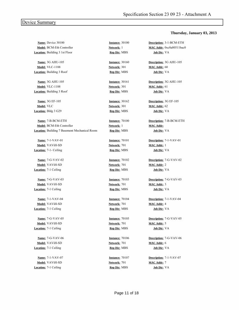
Thursday, January 03, 2013
Device Summary
Name: Device 30100 Instance: 30100 Description: 3-1-BCM-ETHModel: BCM-Eth Controller Network: 1 MAC Addr: 0xc0a80511bac0
Location: Building 3 1st Floor Rep Dir: MBS Job Dir: VA
Name: 3G AHU-105 Instance: 30160 Description: 3G AHU-105Model: VLC-1188 Network: 301 MAC Addr: 60
Location: Building 3 Roof Rep Dir: MBS Job Dir: VA
Name: 3G AHU-105 Instance: 30161 Description: 3G AHU-105Model: VLC 1188 Network: 301 MAC Addr: 61Model: VLC-1188 Network: 301 MAC Addr: 61
Location: Building 3 Roof Rep Dir: MBS Job Dir: VA
Name: 3G EF-105 Instance: 30162 Description: 3G EF-105Model: VLC Network: 301 MAC Addr: 62
Location: Bldg 3 G29 Rep Dir: MBS Job Dir: VA
Name: 7-B-BCM-ETH Instance: 70100 Description: 7-B-BCM-ETHModel: BCM-Eth Controller Network: 1 MAC Addr:
Location: Building 7 Basement Mechanical Room Rep Dir: MBS Job Dir: VA
Name: 7-1-VAV-01 Instance: 70101 Description: 7-1-VAV-01Model: VAViH-SD Network: 701 MAC Addr: 1
Location: 7-1- Ceiling Rep Dir: MBS Job Dir: VA
7 G VAV 02 70102 i i 7 G VAV 02Name: 7-G-VAV-02 Instance: 70102 Description: 7-G-VAV-02Model: VAViH-SD Network: 701 MAC Addr: 2
Location: 7-1 Ceiling Rep Dir: MBS Job Dir: VA
Name: 7-G-VAV-03 Instance: 70103 Description: 7-G-VAV-03Model: VAViH-SD Network: 701 MAC Addr: 3
Location: 7-1 Ceiling Rep Dir: MBS Job Dir: VA
Name: 7-1-VAV-04 Instance: 70104 Description: 7-1-VAV-04Model: VAViH-SD Network: 701 MAC Addr: 4
Location: 7-1 Ceiling Rep Dir: MBS Job Dir: VA
Name: 7-G-VAV-05 Instance: 70105 Description: 7-G-VAV-05Model: VAViH-SD Network: 701 MAC Addr: 5
Location: 7-1 Ceiling Rep Dir: MBS Job Dir: VA
Name: 7-G-VAV-06 Instance: 70106 Description: 7-G-VAV-06Model: VAViH-SD Network: 701 MAC Addr: 6
Location: 7-1 Ceiling Rep Dir: MBS Job Dir: VA
Name: 7-1-VAV-07 Instance: 70107 Description: 7-1-VAV-07Model: VAViH-SD Network: 701 MAC Addr: 7
Location: 7-1 Ceiling Rep Dir: MBS Job Dir: VALocation: 7-1 Ceiling Rep Dir: MBS Job Dir: VA
Page 11 of 18
Specification Section 23 09 23 - Attachment A
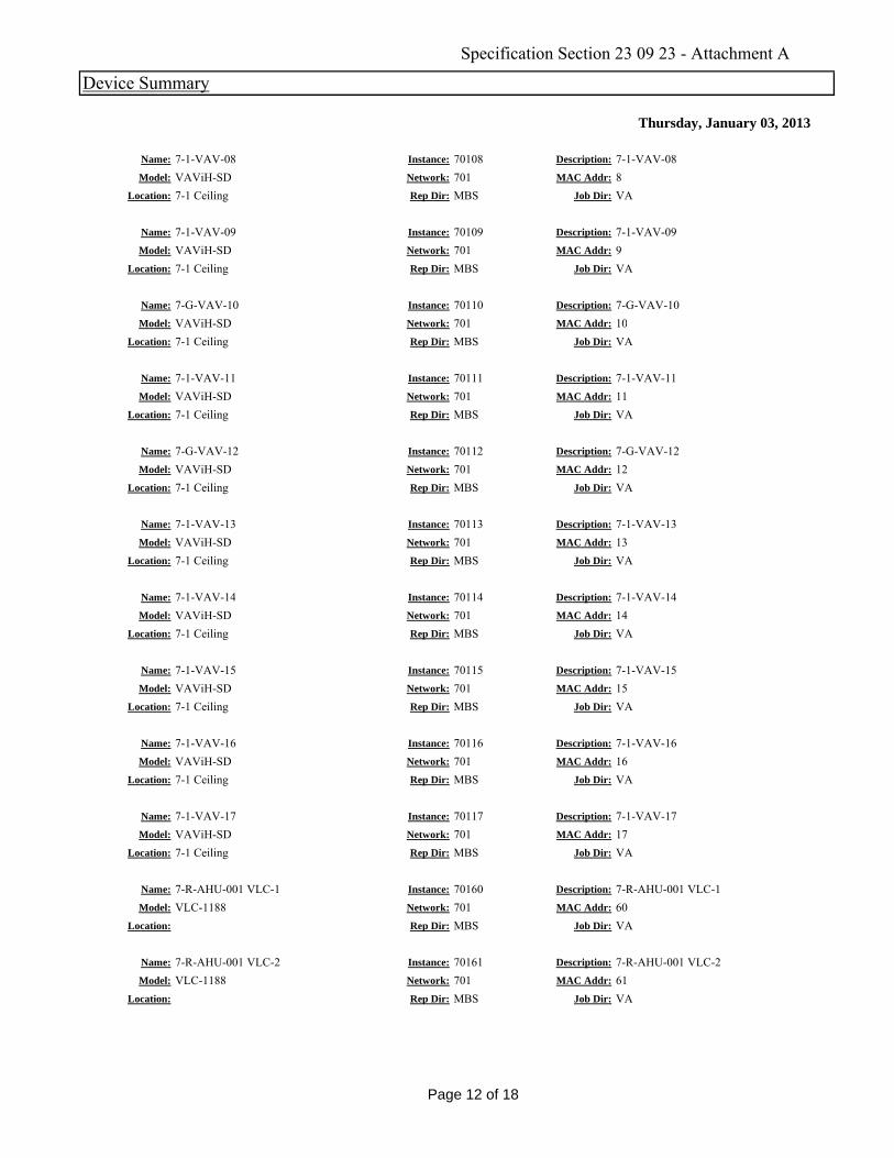
Thursday, January 03, 2013
Device Summary
Name: 7-1-VAV-08 Instance: 70108 Description: 7-1-VAV-08Model: VAViH-SD Network: 701 MAC Addr: 8
Location: 7-1 Ceiling Rep Dir: MBS Job Dir: VA
Name: 7-1-VAV-09 Instance: 70109 Description: 7-1-VAV-09Model: VAViH-SD Network: 701 MAC Addr: 9
Location: 7-1 Ceiling Rep Dir: MBS Job Dir: VA
Name: 7-G-VAV-10 Instance: 70110 Description: 7-G-VAV-10Model: VAViH SD Network: 701 MAC Addr: 10Model: VAViH-SD Network: 701 MAC Addr: 10
Location: 7-1 Ceiling Rep Dir: MBS Job Dir: VA
Name: 7-1-VAV-11 Instance: 70111 Description: 7-1-VAV-11Model: VAViH-SD Network: 701 MAC Addr: 11
Location: 7-1 Ceiling Rep Dir: MBS Job Dir: VA
Name: 7-G-VAV-12 Instance: 70112 Description: 7-G-VAV-12Model: VAViH-SD Network: 701 MAC Addr: 12
Location: 7-1 Ceiling Rep Dir: MBS Job Dir: VA
Name: 7-1-VAV-13 Instance: 70113 Description: 7-1-VAV-13Model: VAViH-SD Network: 701 MAC Addr: 13
Location: 7-1 Ceiling Rep Dir: MBS Job Dir: VA
7 1 VAV 14 70114 i i 7 1 VAV 14Name: 7-1-VAV-14 Instance: 70114 Description: 7-1-VAV-14Model: VAViH-SD Network: 701 MAC Addr: 14
Location: 7-1 Ceiling Rep Dir: MBS Job Dir: VA
Name: 7-1-VAV-15 Instance: 70115 Description: 7-1-VAV-15Model: VAViH-SD Network: 701 MAC Addr: 15
Location: 7-1 Ceiling Rep Dir: MBS Job Dir: VA
Name: 7-1-VAV-16 Instance: 70116 Description: 7-1-VAV-16Model: VAViH-SD Network: 701 MAC Addr: 16
Location: 7-1 Ceiling Rep Dir: MBS Job Dir: VA
Name: 7-1-VAV-17 Instance: 70117 Description: 7-1-VAV-17Model: VAViH-SD Network: 701 MAC Addr: 17
Location: 7-1 Ceiling Rep Dir: MBS Job Dir: VA
Name: 7-R-AHU-001 VLC-1 Instance: 70160 Description: 7-R-AHU-001 VLC-1Model: VLC-1188 Network: 701 MAC Addr: 60
Location: Rep Dir: MBS Job Dir: VA
Name: 7-R-AHU-001 VLC-2 Instance: 70161 Description: 7-R-AHU-001 VLC-2Model: VLC-1188 Network: 701 MAC Addr: 61
Location: Rep Dir: MBS Job Dir: VALocation: Rep Dir: MBS Job Dir: VA
Page 12 of 18
Specification Section 23 09 23 - Attachment A
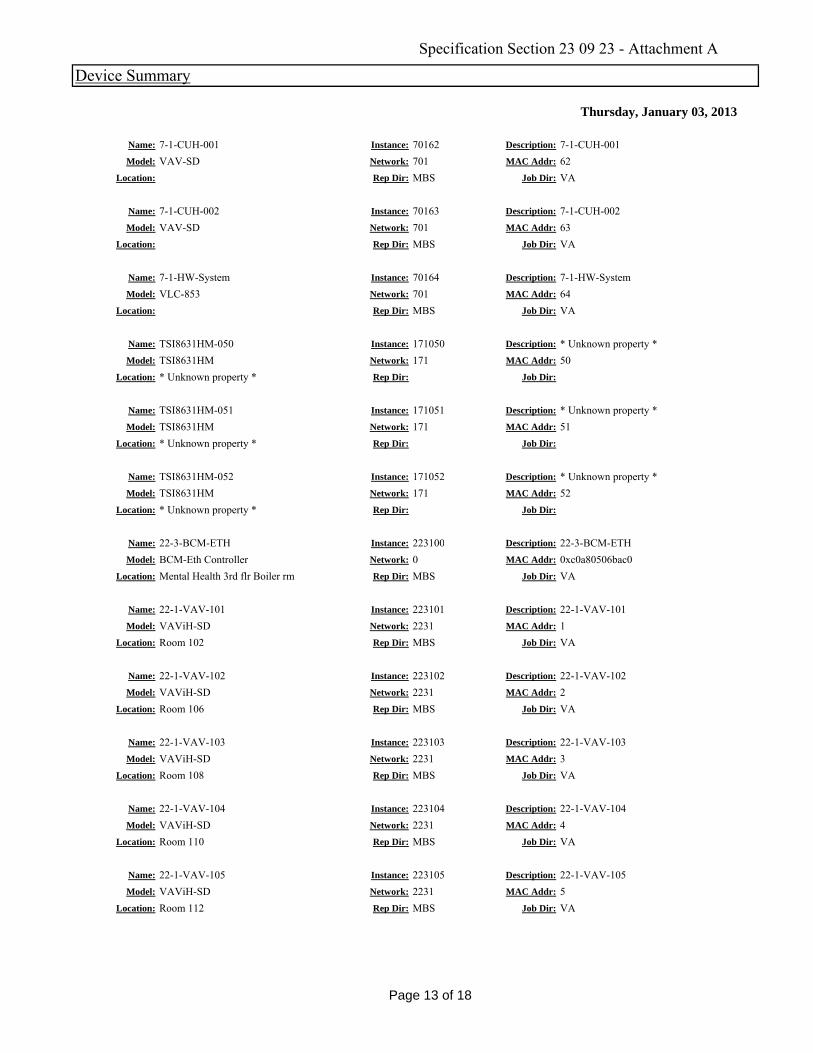
Thursday, January 03, 2013
Device Summary
Name: 7-1-CUH-001 Instance: 70162 Description: 7-1-CUH-001Model: VAV-SD Network: 701 MAC Addr: 62
Location: Rep Dir: MBS Job Dir: VA
Name: 7-1-CUH-002 Instance: 70163 Description: 7-1-CUH-002Model: VAV-SD Network: 701 MAC Addr: 63
Location: Rep Dir: MBS Job Dir: VA
Name: 7-1-HW-System Instance: 70164 Description: 7-1-HW-SystemModel: VLC 853 Network: 701 MAC Addr: 64Model: VLC-853 Network: 701 MAC Addr: 64
Location: Rep Dir: MBS Job Dir: VA
Name: TSI8631HM-050 Instance: 171050 Description: * Unknown property *Model: TSI8631HM Network: 171 MAC Addr: 50
Location: * Unknown property * Rep Dir: Job Dir:
Name: TSI8631HM-051 Instance: 171051 Description: * Unknown property *Model: TSI8631HM Network: 171 MAC Addr: 51
Location: * Unknown property * Rep Dir: Job Dir:
Name: TSI8631HM-052 Instance: 171052 Description: * Unknown property *Model: TSI8631HM Network: 171 MAC Addr: 52
Location: * Unknown property * Rep Dir: Job Dir:
22 3 BCM ETH 223100 i i 22 3 BCM ETHName: 22-3-BCM-ETH Instance: 223100 Description: 22-3-BCM-ETHModel: BCM-Eth Controller Network: 0 MAC Addr: 0xc0a80506bac0
Location: Mental Health 3rd flr Boiler rm Rep Dir: MBS Job Dir: VA
Name: 22-1-VAV-101 Instance: 223101 Description: 22-1-VAV-101Model: VAViH-SD Network: 2231 MAC Addr: 1
Location: Room 102 Rep Dir: MBS Job Dir: VA
Name: 22-1-VAV-102 Instance: 223102 Description: 22-1-VAV-102Model: VAViH-SD Network: 2231 MAC Addr: 2
Location: Room 106 Rep Dir: MBS Job Dir: VA
Name: 22-1-VAV-103 Instance: 223103 Description: 22-1-VAV-103Model: VAViH-SD Network: 2231 MAC Addr: 3
Location: Room 108 Rep Dir: MBS Job Dir: VA
Name: 22-1-VAV-104 Instance: 223104 Description: 22-1-VAV-104Model: VAViH-SD Network: 2231 MAC Addr: 4
Location: Room 110 Rep Dir: MBS Job Dir: VA
Name: 22-1-VAV-105 Instance: 223105 Description: 22-1-VAV-105Model: VAViH-SD Network: 2231 MAC Addr: 5
Location: Room 112 Rep Dir: MBS Job Dir: VALocation: Room 112 Rep Dir: MBS Job Dir: VA
Page 13 of 18
Specification Section 23 09 23 - Attachment A
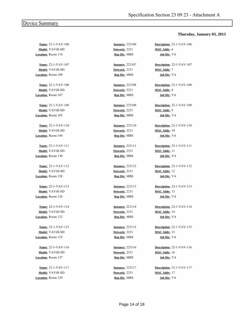
Thursday, January 03, 2013
Device Summary
Name: 22-1-VAV-106 Instance: 223106 Description: 22-1-VAV-106Model: VAViH-SD Network: 2231 MAC Addr: 6
Location: Room 114 Rep Dir: MBS Job Dir: VA
Name: 22-1-VAV-107 Instance: 223107 Description: 22-1-VAV-107Model: VAViH-SD Network: 2231 MAC Addr: 7
Location: Room 109 Rep Dir: MBS Job Dir: VA
Name: 22-1-VAV-108 Instance: 223108 Description: 22-1-VAV-108Model: VAViH SD Network: 2231 MAC Addr: 8Model: VAViH-SD Network: 2231 MAC Addr: 8
Location: Room 107 Rep Dir: MBS Job Dir: VA
Name: 22-1-VAV-109 Instance: 223109 Description: 22-1-VAV-109Model: VAViH-SD Network: 2231 MAC Addr: 9
Location: Room 105 Rep Dir: MBS Job Dir: VA
Name: 22-1-VAV-110 Instance: 223110 Description: 22-1-VAV-110Model: VAViH-SD Network: 2231 MAC Addr: 10
Location: Room 144 Rep Dir: MBS Job Dir: VA
Name: 22-1-VAV-111 Instance: 223111 Description: 22-1-VAV-111Model: VAViH-SD Network: 2231 MAC Addr: 11
Location: Room 130 Rep Dir: MBS Job Dir: VA
22 1 VAV 112 223112 i i 22 1 VAV 112Name: 22-1-VAV-112 Instance: 223112 Description: 22-1-VAV-112Model: VAViH-SD Network: 2231 MAC Addr: 12
Location: Room 128 Rep Dir: MBS Job Dir: VA
Name: 22-1-VAV-113 Instance: 223113 Description: 22-1-VAV-113Model: VAViH-SD Network: 2231 MAC Addr: 13
Location: Room 126 Rep Dir: MBS Job Dir: VA
Name: 22-1-VAV-114 Instance: 223114 Description: 22-1-VAV-114Model: VAViH-SD Network: 2231 MAC Addr: 14
Location: Room 123 Rep Dir: MBS Job Dir: VA
Name: 22-1-VAV-115 Instance: 223115 Description: 22-1-VAV-115Model: VAViH-SD Network: 2231 MAC Addr: 15
Location: Room 125 Rep Dir: MBS Job Dir: VA
Name: 22-1-VAV-116 Instance: 223116 Description: 22-1-VAV-116Model: VAViH-SD Network: 2231 MAC Addr: 16
Location: Room 127 Rep Dir: MBS Job Dir: VA
Name: 22-1-VAV-117 Instance: 223117 Description: 22-1-VAV-117Model: VAViH-SD Network: 2231 MAC Addr: 17
Location: Room 129 Rep Dir: MBS Job Dir: VALocation: Room 129 Rep Dir: MBS Job Dir: VA
Page 14 of 18
Specification Section 23 09 23 - Attachment A
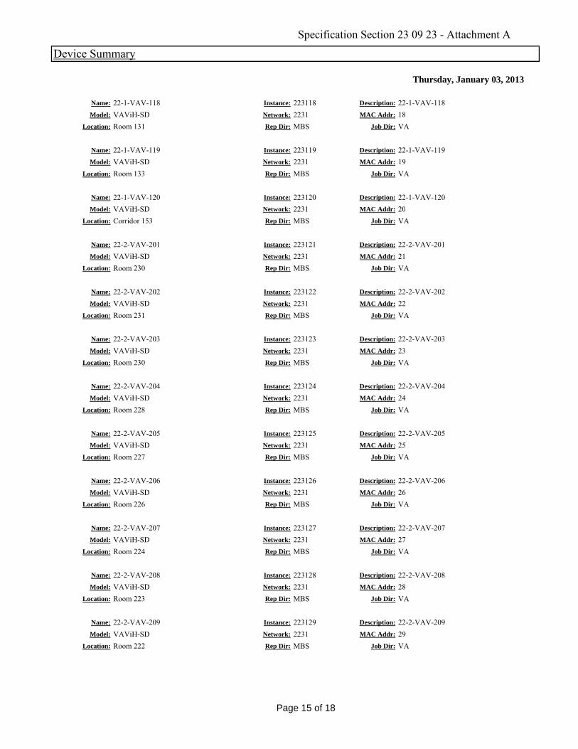
Thursday, January 03, 2013
Device Summary
Name: 22-1-VAV-118 Instance: 223118 Description: 22-1-VAV-118Model: VAViH-SD Network: 2231 MAC Addr: 18
Location: Room 131 Rep Dir: MBS Job Dir: VA
Name: 22-1-VAV-119 Instance: 223119 Description: 22-1-VAV-119Model: VAViH-SD Network: 2231 MAC Addr: 19
Location: Room 133 Rep Dir: MBS Job Dir: VA
Name: 22-1-VAV-120 Instance: 223120 Description: 22-1-VAV-120Model: VAViH SD Network: 2231 MAC Addr: 20Model: VAViH-SD Network: 2231 MAC Addr: 20
Location: Corridor 153 Rep Dir: MBS Job Dir: VA
Name: 22-2-VAV-201 Instance: 223121 Description: 22-2-VAV-201Model: VAViH-SD Network: 2231 MAC Addr: 21
Location: Room 230 Rep Dir: MBS Job Dir: VA
Name: 22-2-VAV-202 Instance: 223122 Description: 22-2-VAV-202Model: VAViH-SD Network: 2231 MAC Addr: 22
Location: Room 231 Rep Dir: MBS Job Dir: VA
Name: 22-2-VAV-203 Instance: 223123 Description: 22-2-VAV-203Model: VAViH-SD Network: 2231 MAC Addr: 23
Location: Room 230 Rep Dir: MBS Job Dir: VA
22 2 VAV 204 223124 i i 22 2 VAV 204Name: 22-2-VAV-204 Instance: 223124 Description: 22-2-VAV-204Model: VAViH-SD Network: 2231 MAC Addr: 24
Location: Room 228 Rep Dir: MBS Job Dir: VA
Name: 22-2-VAV-205 Instance: 223125 Description: 22-2-VAV-205Model: VAViH-SD Network: 2231 MAC Addr: 25
Location: Room 227 Rep Dir: MBS Job Dir: VA
Name: 22-2-VAV-206 Instance: 223126 Description: 22-2-VAV-206Model: VAViH-SD Network: 2231 MAC Addr: 26
Location: Room 226 Rep Dir: MBS Job Dir: VA
Name: 22-2-VAV-207 Instance: 223127 Description: 22-2-VAV-207Model: VAViH-SD Network: 2231 MAC Addr: 27
Location: Room 224 Rep Dir: MBS Job Dir: VA
Name: 22-2-VAV-208 Instance: 223128 Description: 22-2-VAV-208Model: VAViH-SD Network: 2231 MAC Addr: 28
Location: Room 223 Rep Dir: MBS Job Dir: VA
Name: 22-2-VAV-209 Instance: 223129 Description: 22-2-VAV-209Model: VAViH-SD Network: 2231 MAC Addr: 29
Location: Room 222 Rep Dir: MBS Job Dir: VALocation: Room 222 Rep Dir: MBS Job Dir: VA
Page 15 of 18
Specification Section 23 09 23 - Attachment A

Thursday, January 03, 2013
Device Summary
Name: 22-2-VAV-210 Instance: 223130 Description: 22-2-VAV-210Model: VAViH-SD Network: 2231 MAC Addr: 30
Location: Room 213 Rep Dir: MBS Job Dir: VA
Name: 22-2-VAV-211 Instance: 223131 Description: 22-2-VAV-211Model: VAViH-SD Network: 2231 MAC Addr: 31
Location: Room 211 Rep Dir: MBS Job Dir: VA
Name: 22-2-VAV-212 Instance: 223132 Description: 22-2-VAV-212Model: VAViH SD Network: 2231 MAC Addr: 32Model: VAViH-SD Network: 2231 MAC Addr: 32
Location: Room 209 Rep Dir: MBS Job Dir: VA
Name: 22-2-VAV-213 Instance: 223133 Description: 22-2-VAV-213Model: VAViH-SD Network: 2231 MAC Addr: 33
Location: Room 203 Rep Dir: MBS Job Dir: VA
Name: 22-2-VAV-214 Instance: 223134 Description: 22-2-VAV-214Model: VAViH-SD Network: 2231 MAC Addr: 34
Location: Room 253 Rep Dir: MBS Job Dir: VA
Name: 22-2-VAV-215 Instance: 223135 Description: 22-2-VAV-215Model: VAViH-SD Network: 2231 MAC Addr: 35
Location: Room 220 Rep Dir: MBS Job Dir: VA
22 1 CUH 1 E S i 223136 i i 22 1 CUH 1 E S iName: 22-1-CUH-1 E Stair Instance: 223136 Description: 22-1-CUH-1 E StairModel: VAV-SD2A Network: 2231 MAC Addr: 36
Location: Stair 1 Rep Dir: MBS Job Dir: VA
Name: CUH-2 Instance: 223137 Description: 22-1-CUH-2 W StairModel: VAV-SD2A Network: 2231 MAC Addr: 37
Location: Stair 1 Rep Dir: MBS Job Dir: VA
Name: 22-1-CUH-3 NE Entry Instance: 223138 Description: 22-1-CUH-3 NE EntryModel: VAV-SD2A Network: 2231 MAC Addr: 38
Location: Entry Vest Rep Dir: MBS Job Dir: VA
Name: 22-1-CUH-4 SE Entry Instance: 223139 Description: 22-1-CUH-4 SE EntryModel: VAV-SD2A Network: 2231 MAC Addr: 39
Location: Entry Vest Rep Dir: MBS Job Dir: VA
Name: 22-3--VAV-301 Instance: 223140 Description: 22-3--VAV-301Model: VAViH-SD Network: 2231 MAC Addr: 40
Location: Room 300 Rep Dir: MBS Job Dir: VA
Name: 22-3-VAV-302 Instance: 223141 Description: 22-3-VAV-302Model: VAViH-SD Network: 2231 MAC Addr: 41
Location: Room 310 Rep Dir: MBS Job Dir: VALocation: Room 310 Rep Dir: MBS Job Dir: VA
Page 16 of 18
Specification Section 23 09 23 - Attachment A

Thursday, January 03, 2013
Device Summary
Name: 22-3-VAV-303 Instance: 223142 Description: 22-3-VAV-303Model: VAViH-SD Network: 2231 MAC Addr: 42
Location: Room 324 Rep Dir: MBS Job Dir: VA
Name: 22-1-UH-2+3 Instance: 223143 Description: 22-1-UH-2+3Model: VAV-SD2A Network: 2231 MAC Addr: 43
Location: Room 100 Rep Dir: MBS Job Dir: VA
Name: 22-3-ERV-1 Instance: 223144 Description: 22-3-ERV-1Model: VLC 853 Network: 2231 MAC Addr: 44Model: VLC-853 Network: 2231 MAC Addr: 44
Location: 3rd Floor Connecting Corridor Rep Dir: MBS Job Dir: VA
Name: 22-3-FCU 1 and 2 Instance: 223145 Description: 22-3-FCU 1 and 2Model: VLC-444 Network: 2231 MAC Addr: 45
Location: 3rd Floor Connecting Corridor Rep Dir: MBS Job Dir: VA
Name: 22-3-ERV-2 Instance: 223146 Description: 22-3-ERV-2Model: VLC-853 Network: 2231 MAC Addr: 46
Location: 3rd Floor Connecting Corridor Rep Dir: MBS Job Dir: VA
Name: 22-3-FCU 3,4,5 Instance: 223147 Description: 22-3-FCU 3,4,5Model: VLC-444 Network: 2231 MAC Addr: 47
Location: 3rd Floor Connecting Corridor Rep Dir: MBS Job Dir: VA
223148 i iName: Instance: 223148 Description:
Model: VAViH-SD Network: 2231 MAC Addr: 48Location: Rep Dir: MBS Job Dir: VA
Name: Instance: 223149 Description:
Model: VAViH-SD Network: 2231 MAC Addr: 49Location: Rep Dir: MBS Job Dir: VA
Name: Instance: 223150 Description:
Model: VAViH-SD Network: 2231 MAC Addr: 50Location: Rep Dir: MBS Job Dir: VA
Name: Instance: 223151 Description:
Model: VAViH-SD Network: 2231 MAC Addr: 51Location: Rep Dir: MBS Job Dir: VA
Name: Instance: 223152 Description:
Model: VAViH-SD Network: 2231 MAC Addr: 52Location: Rep Dir: MBS Job Dir: VA
Name: Instance: 223153 Description:
Model: VAViH-SD Network: 2231 MAC Addr: 53Location: Rep Dir: MBS Job Dir: VALocation: Rep Dir: MBS Job Dir: VA
Page 17 of 18
Specification Section 23 09 23 - Attachment A
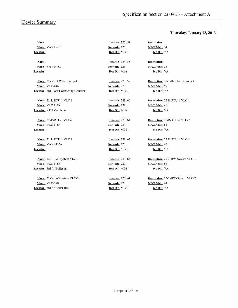
Thursday, January 03, 2013
Device Summary
Name: Instance: 223154 Description:
Model: VAViH-SD Network: 2231 MAC Addr: 54Location: Rep Dir: MBS Job Dir: VA
Name: Instance: 223155 Description:
Model: VAViH-SD Network: 2231 MAC Addr: 55Location: Rep Dir: MBS Job Dir: VA
Name: 22-3-Hot Water Pump 4 Instance: 223159 Description: 22-3-Hot Water Pump 4Model: VLC 444 Network: 2231 MAC Addr: 59Model: VLC-444 Network: 2231 MAC Addr: 59
Location: 3rd Floor Connecting Corridor Rep Dir: MBS Job Dir: VA
Name: 22-R-RTU-1 VLC-1 Instance: 223160 Description: 22-R-RTU-1 VLC-1Model: VLC-1188 Network: 2231 MAC Addr: 60
Location: RTU Vestibule Rep Dir: MBS Job Dir: VA
Name: 22-R-RTU-1 VLC-2 Instance: 223161 Description: 22-R-RTU-1 VLC-2Model: VLC-1188 Network: 2231 MAC Addr: 61
Location: Rep Dir: MBS Job Dir: VA
Name: 22-R-RTU-1 VLC-3 Instance: 223162 Description: 22-R-RTU-1 VLC-3Model: VAV-SD2A Network: 2231 MAC Addr: 62
Location: Rep Dir: MBS Job Dir: VA
22 3 HW S VLC 1 223163 i i 22 3 HW S VLC 1Name: 22-3-HW-System VLC-1 Instance: 223163 Description: 22-3-HW-System VLC-1Model: VLC-1188 Network: 2231 MAC Addr: 63
Location: 3rd flr Boiler rm Rep Dir: MBS Job Dir: VA
Name: 22-3-HW-System VLC-2 Instance: 223164 Description: 22-3-HW-System VLC-2Model: VLC-550 Network: 2231 MAC Addr: 64
Location: 3rd flr Boiler Rm Rep Dir: MBS Job Dir: VA
Page 18 of 18
Specification Section 23 09 23 - Attachment A
03-10
23 21 13-1
SECTION 23 21 13 HYDRONIC PIPING
PART 1 - GENERAL
1.1 DESCRIPTION
A. Water piping to connect HVAC equipment, including the following:
1. Chilled water, heating hot water and drain piping.
1.2 RELATED WORK
A. Section 01 00 00, GENERAL REQUIREMENTS.
B. Section 01 33 23, SHOP DRAWINGS, PRODUCT DATA, and SAMPLES.
C. Section 23 05 11, COMMON WORK RESULTS FOR HVAC and STEAM GENERATION:
General mechanical requirements and items, which are common to more
than one section of Division 23.
D. Section 23 07 11, HVAC, PLUMBING, and BOILER PLANT INSULATION: Piping
insulation.
E. Section 23 09 23, DIRECT-DIGITAL CONTROL SYSTEM FOR HVAC: Temperature
and pressure sensors and valve operators.
1.3 QUALITY ASSURANCE
A. Section 23 05 11, COMMON WORK RESULTS FOR HVAC and STEAM GENERATION,
which includes welding qualifications.
B. Submit prior to welding of steel piping a certificate of Welder’s
certification. The certificate shall be current and not more than one
year old.
C. For mechanical pressed sealed fittings, only tools of fitting
manufacturer shall be used.
D. Mechanical pressed fittings shall be installed by factory trained
workers.
E. All grooved joint couplings, fittings, valves, and specialties shall be
the products of a single manufacturer. Grooving tools shall be the
same manufacturer as the grooved components.
1. All castings used for coupling housings, fittings, valve bodies,
etc., shall be date stamped for quality assurance and traceability.
1.4 SUBMITTALS
A. Submit in accordance with Section 01 33 23, SHOP DRAWINGS, PRODUCT
DATA, and SAMPLES.
B. Manufacturer's Literature and Data:
1. Pipe and tubing, with specification, class or type, and schedule.
03-10
23 21 13-2
2. Pipe fittings, including miscellaneous adapters and special
fittings.
3. Flanges, gaskets and bolting.
4. Grooved joint couplings and fittings.
5. Valves of all types.
6. Gages.
7. Thermometers and test wells.
C. Submit the welder’s qualifications in the form of a current (less than
one year old) and formal certificate.
D. Coordination Drawings: Refer to Article, SUBMITTALS of Section 23 05
11, COMMON WORK RESULTS FOR HVAC and STEAM GENERATION.
E. As-Built Piping Diagrams: Provide drawing as follows for chilled water,
and heating hot water system and other piping systems and equipment.
1. One wall-mounted stick file with complete set of prints. Mount stick
file in the chiller plant or control room along with control diagram
stick file.
2. One complete set of reproducible drawings.
3. One complete set of drawings in electronic Autocad and pdf format.
1.5 APPLICABLE PUBLICATIONS
A. The publications listed below form a part of this specification to the
extent referenced. The publications are referenced in the text by the
basic designation only. American National Standards Institute, Inc.
B. American Society of Mechanical Engineers/American National Standards
Institute, Inc. (ASME/ANSI):
B1.20.1-83(R2006).......Pipe Threads, General Purpose (Inch)
B16.4-06................Gray Iron Threaded FittingsB16.18-01 Cast
Copper Alloy Solder joint Pressure fittings
B16.23-02...............Cast Copper Alloy Solder joint Drainage
fittings
B40.100-05..............Pressure Gauges and Gauge Attachments
C. American National Standards Institute, Inc./Fluid Controls Institute
(ANSI/FCI):
70-2-2006...............Control Valve Seat Leakage
D. American Society of Mechanical Engineers (ASME):
B16.1-98................Cast Iron Pipe Flanges and Flanged Fittings
B16.3-2006..............Malleable Iron Threaded Fittings: Class 150 and
300
03-10
23 21 13-3
B16.4-2006..............Gray Iron Threaded Fittings: (Class 125 and
250)
B16.5-2003..............Pipe Flanges and Flanged Fittings: NPS ½
through NPS 24 Metric/Inch Standard
B16.9-07................Factory Made Wrought Butt Welding Fittings
B16.11-05...............Forged Fittings, Socket Welding and Threaded
B16.18-01...............Cast Copper Alloy Solder Joint Pressure
Fittings
B16.22-01...............Wrought Copper and Bronze Solder Joint Pressure
Fittings.
B16.24-06...............Cast Copper Alloy Pipe Flanges and Flanged
Fittings
B16.39-06...............Malleable Iron Threaded Pipe Unions
B16.42-06...............Ductile Iron Pipe Flanges and Flanged Fittings
B31.1-08................Power Piping
E. American Society for Testing and Materials (ASTM):
A47/A47M-99 (2004)......Ferritic Malleable Iron Castings
A53/A53M-07.............Standard Specification for Pipe, Steel, Black
and Hot-Dipped, Zinc-Coated, Welded and
Seamless
A106/A106M-08...........Standard Specification for Seamless Carbon
Steel Pipe for High-Temperature Service
A126-04.................Standard Specification for Gray Iron Castings
for Valves, Flanges, and Pipe Fittings
A183-03 ................ Standard Specification for Carbon Steel Track
Bolts and Nuts
A216/A216M-08 .......... Standard Specification for Steel Castings,
Carbon, Suitable for Fusion Welding, for High
Temperature Service
A234/A234M-07 .......... Piping Fittings of Wrought Carbon Steel and
Alloy Steel for Moderate and High Temperature
Service
A307-07 ................ Standard Specification for Carbon Steel Bolts
and Studs, 60,000 PSI Tensile Strength
A536-84 (2004) ......... Standard Specification for Ductile Iron Castings
A615/A615M-08 .......... Deformed and Plain Carbon Steel Bars for
Concrete Reinforcement
03-10
23 21 13-4
A653/A 653M-08 ......... Steel Sheet, Zinc-Coated (Galvanized) or Zinc-
Iron Alloy Coated (Galvannealed) By the Hot-Dip
Process
B32-08 ................. Standard Specification for Solder Metal
B62-02 ................. Standard Specification for Composition Bronze or
Ounce Metal Castings
B88-03 ................. Standard Specification for Seamless Copper Water
Tube
B209-07 ................ Aluminum and Aluminum Alloy Sheet and Plate
C177-04 ............... Standard Test Method for Steady State Heat Flux
Measurements and Thermal Transmission Properties
by Means of the Guarded Hot Plate Apparatus
C478-09 ................ Precast Reinforced Concrete Manhole Sections
C533-07 ................ Calcium Silicate Block and Pipe Thermal
Insulation
C552-07 ................ Cellular Glass Thermal Insulation
D3350-08 ............... Polyethylene Plastics Pipe and Fittings
Materials
C591-08 ................ Unfaced Preformed Rigid Cellular
Polyisocyanurate Thermal Insulation
D1784-08 ............... Rigid Poly (Vinyl Chloride) (PVC) Compounds and
Chlorinated Poly (Vinyl Chloride) (CPVC)
Compound
D1785-06 ............... Poly (Vinyl Chloride0 (PVC) Plastic Pipe,
Schedules 40, 80 and 120
D2241-05 ............... Poly (Vinyl Chloride) (PVC) Pressure Rated Pipe
(SDR Series)
F439-06 ................ Standard Specification for Chlorinated Poly
(Vinyl Chloride) (CPVC) Plastic Pipe Fittings,
Schedule 80
F441/F441M-02 .......... Standard Specification for Chlorinated Poly
(Vinyl Chloride) (CPVC) Plastic Pipe, Schedules
40 and 80
F477-08 ................ Elastomeric Seals Gaskets) for Joining Plastic
Pipe
F. American Water Works Association (AWWA):
C110-08.................Ductile Iron and Grey Iron Fittings for Water

03-10
23 21 13-5
C203-02.................Coal Tar Protective Coatings and Linings for
Steel Water Pipe Lines Enamel and Tape Hot
Applied
G. American Welding Society (AWS):
B2.1-02.................Standard Welding Procedure Specification
H. Copper Development Association, Inc. (CDA):
CDA A4015-06............Copper Tube Handbook
I. Expansion Joint Manufacturer’s Association, Inc. (EJMA):
EMJA-2003...............Expansion Joint Manufacturer’s Association
Standards, Ninth Edition
J. Manufacturers Standardization Society (MSS) of the Valve and Fitting
Industry, Inc.:
SP-67-02a...............Butterfly Valves
SP-70-06................Gray Iron Gate Valves, Flanged and Threaded
Ends
SP-71-05................Gray Iron Swing Check Valves, Flanged and
Threaded Ends
SP-80-08................Bronze Gate, Globe, Angle and Check Valves
SP-85-02................Cast Iron Globe and Angle Valves, Flanged and
Threaded Ends
SP-110-96...............Ball Valves Threaded, Socket-Welding, Solder
Joint, Grooved and Flared Ends
SP-125-00...............Gray Iron and Ductile Iron In-line, Spring
Loaded, Center-Guided Check Valves
K. National Sanitation Foundation/American National Standards Institute,
Inc. (NSF/ANSI):
14-06...................Plastic Piping System Components and Related
Materials
50-2009a................Equipment for Swimming Pools, Spas, Hot Tubs
and other Recreational Water Facilities –
Evaluation criteria for materials, components,
products, equipment and systems for use at
recreational water facilities
61-2008.................Drinking Water System Components – Health
Effects
03-10
23 21 13-6
L. Tubular Exchanger Manufacturers Association: TEMA 9th Edition, 2007
PART 2 - PRODUCTS
2.1 PIPE AND EQUIPMENT SUPPORTS, PIPE SLEEVES, AND WALL AND CEILING PLATES
A. Provide in accordance with Section 23 05 11, COMMON WORK RESULTS FOR
HVAC and STEAM GENERATION.
2.2 PIPE AND TUBING
A. Chilled Water, Heating Hot Water:
1. Steel: ASTM A53 Grade B, seamless or ERW, Schedule 40.
2. Copper water tube option: ASTM B88, Type K or L, hard drawn.
B. Pipe supports, including insulation shields, for above ground piping:
Section 23 05 11, COMMON WORK RESULTS FOR HVAC.
2.3 FITTINGS FOR STEEL PIPE
A. 50 mm (2 inches) and Smaller: Screwed or welded joints.
1. Butt welding: ASME B16.9 with same wall thickness as connecting
piping.
2. Forged steel, socket welding or threaded: ASME B16.11.
3. Screwed: 150 pound malleable iron, ASME B16.3. 125 pound cast iron,
ASME B16.4, may be used in lieu of malleable iron. Bushing reduction
of a single pipe size, or use of close nipples, is not acceptable.
4. Unions: ASME B16.39.
5. Water hose connection adapter: Brass, pipe thread to 20 mm (3/4
inch) garden hose thread, with hose cap nut.
B. 65 mm (2-1/2 inches) and Larger: Welded or flanged joints. Contractor’s
option: Grooved mechanical couplings and fittings are optional.
1. Butt welding fittings: ASME B16.9 with same wall thickness as
connecting piping. Elbows shall be long radius type, unless
otherwise noted.
2. Welding flanges and bolting: ASME B16.5:
a. Water service: Weld neck or slip-on, plain face, with 6 mm (1/8
inch) thick full face neoprene gasket suitable for 104 degrees C
(220 degrees F).
1) Contractor's option: Convoluted, cold formed 150 pound steel
flanges, with teflon gaskets, may be used for water service.
b. Flange bolting: Carbon steel machine bolts or studs and nuts,
ASTM A307, Grade B.
C. Welded Branch and Tap Connections: Forged steel weldolets, or
branchlets and threadolets may be used for branch connections up to one
03-10
23 21 13-7
pipe size smaller than the main. Forged steel half-couplings, ASME
B16.11 may be used for drain, vent and gage connections.
D. Grooved Mechanical Pipe Couplings and Fittings (Contractor’s Option):
Grooved Mechanical Pipe Couplings and Fittings may be used, with cut or
roll grooved pipe, in water service up to 110 degrees C (230 degrees F)
in lieu of welded, screwed or flanged connections. All joints must be
rigid type.
1. Grooved mechanical couplings: Malleable iron, ASTM A47 or ductile
iron, ASTM A536, fabricated in two or more parts, securely held
together by two or more track-head, square, or oval-neck bolts, ASTM
A449 and A183.
2. Gaskets: Rubber product recommended by the coupling manufacturer for
the intended service.
3. Grooved end fittings: Malleable iron, ASTM A47; ductile iron, ASTM
A536; or steel, ASTM A53 or A106, designed to accept grooved
mechanical couplings. Tap-in type branch connections are acceptable.
2.4 FITTINGS FOR COPPER TUBING
A. Joints:
1. Solder Joints: Joints shall be made up in accordance with
recommended practices of the materials applied. Apply 95/5 tin and
antimony on all copper piping.
2. Mechanically formed tee connection in water and drain piping: Form
mechanically extracted collars in a continuous operation by drilling
pilot hole and drawing out tube surface to form collar, having a
height of not less than three times the thickness of tube wall.
Adjustable collaring device shall insure proper tolerance and
complete uniformity of the joint. Notch and dimple joining branch
tube in a single process to provide free flow where the branch tube
penetrates the fitting.
B. Bronze Flanges and Flanged Fittings: ASME B16.24.
C. Fittings: ANSI/ASME B16.18 cast copper or ANSI/ASME B16.22 solder
wrought copper.
2.5 DIELECTRIC FITTINGS
A. Provide where copper tubing and ferrous metal pipe are joined.
B. 50 mm (2 inches) and Smaller: Threaded dielectric union, ASME B16.39.
C. 65 mm (2 1/2 inches) and Larger: Flange union with dielectric gasket
and bolt sleeves, ASME B16.42.
D. Temperature Rating, 99 degrees C (210 degrees F).

03-10
23 21 13-8
E. Contractor’s option: On pipe sizes 2” and smaller, screwed end brass
ball valves or dielectric nipples may be used in lieu of dielectric
unions.
2.6 SCREWED JOINTS
A. Pipe Thread: ANSI B1.20.
B. Lubricant or Sealant: Oil and graphite or other compound approved for
the intended service.
2.7 VALVES
A. Asbestos packing is not acceptable.
B. All valves of the same type shall be products of a single manufacturer.
C. Shut-Off Valves
1. Ball Valves (Pipe sizes 2” and smaller): MSS-SP 110, screwed or
solder connections, brass or bronze body with chrome-plated ball
with full port and Teflon seat at 600 psig working pressure rating.
Provide stem extension to allow operation without interfering with
pipe insulation.
2. Butterfly Valves (Pipe Sizes 2-1/2” and larger): Provide stem
extension to allow 50 mm (2 inches) of pipe insulation without
interfering with valve operation. MSS-SP 67, flange lug type or
grooved end rated 1205 kPa (175 psig) working pressure at 93 degrees
C (200 degrees F). Valves shall be ANSI Leakage Class VI and rated
for bubble tight shut-off to full valve pressure rating. Valve
shall be rated for dead end service and bi-directional flow
capability to full rated pressure. Not permitted for direct buried
pipe applications.
a. Body: Cast iron, ASTM A126, Class B. Malleable iron, ASTM A47
electro-plated, or ductile iron, ASTM A536, Grade 65-45-12
electro-plated.
b. Trim: Bronze, aluminum bronze, or 300 series stainless steel
disc, bronze bearings, 316 stainless steel shaft and
manufacturer's recommended resilient seat. Resilient seat shall
be field replaceable, and fully line the body to completely
isolate the body from the product. A phosphate coated steel shaft
or stem is acceptable, if the stem is completely isolated from
the product.
c. Actuators: Field interchangeable. Valves for balancing service
shall have adjustable memory stop to limit open position.
03-10
23 21 13-9
1) Valves 150 mm (6 inches) and smaller: Lever actuator with
minimum of seven locking positions, except where chain wheel
is required.
2) Valves 200 mm (8 inches) and larger: Enclosed worm gear with
handwheel, and where required, chain-wheel operator.
3) 3. Gate Valves (Contractor’s Option in lieu of Ball or
Butterfly Valves):
a) 50 mm (2 inches) and smaller: MSS-SP 80, Bronze, 1034 kPa
(150 psig), wedge disc, rising stem, union bonnet.
b) 65 mm (2 1/2 inches) and larger: Flanged, outside screw and
yoke. MSS-SP 70, iron body, bronze mounted, 861 kPa (125
psig) wedge disc.
D. Globe and Angle Valves
1. Globe Valves
a. 50 mm (2 inches) and smaller: MSS-SP 80, bronze, 1034 kPa (150
lb.) Globe valves shall be union bonnet with metal plug type
disc.
b. 65 mm (2 1/2 inches) and larger: 861 kPa (125 psig), flanged,
iron body, bronze trim, MSS-SP-85 for globe valves.
2. Angle Valves:
a. 50 mm (2 inches) and smaller: MSS-SP 80, bronze, 1034 kPa (150
lb.) Angle valves shall be union bonnet with metal plug type
disc.
b. 65 mm (2 1/2 inches) and larger: 861 kPa (125 psig), flanged,
iron body, bronze trim, MSS-SP-85 for angle.
E. Check Valves
1. Swing Check Valves:
a. 50 mm (2 inches) and smaller: MSS-SP 80, bronze, 1034 kPa (150
lb.), 45 degree swing disc.
b. 65 mm (2 1/2 inches) and larger: 861 kPa (125 psig), flanged,
iron body, bronze trim, MSS-SP-71 for check valves.
2. Non-Slam or Silent Check Valve: Spring loaded double disc swing
check or internally guided flat disc lift type check for bubble
tight shut-off. Provide where check valves are shown in chilled
water and hot water piping. Check valves incorporating a balancing
feature may be used.
03-10
23 21 13-10
a. Body: MSS-SP 125 cast iron, ASTM A126, Class B, or steel, ASTM
A216, Class WCB, or ductile iron, ASTM 536, flanged, grooved, or
wafer type.
b. Seat, disc and spring: 18-8 stainless steel, or bronze, ASTM B62.
Seats may be elastomer material.
F. Water Flow Balancing Valves: For flow regulation and shut-off. Valves
shall be line size rather than reduced to control valve size.
1. Ball or Globe style valve.
2. A dual purpose flow balancing valve and adjustable flow meter, with
bronze or cast iron body, calibrated position pointer, valved
pressure taps or quick disconnects with integral check valves and
preformed polyurethane insulating enclosure.
3. Provide a readout kit including flow meter, readout probes, hoses,
flow charts or calculator, and carrying case.
H. Automatic Balancing Control Valves: Factory calibrated to maintain
constant flow (plus or minus five percent) over system pressure
fluctuations of at least 10 times the minimum required for control.
Provide standard pressure taps and four sets of capacity charts. Valves
shall be line size and be one of the following designs:
1. Gray iron (ASTM A126) or brass body rated 1205 kPa (175 psig) at 93
degrees C (200 degrees F), with stainless steel piston and spring.
2. Brass or ferrous body designed for 2067 kPa (300 psig) service at
121 degrees C (250 degrees F), with corrosion resistant, tamper
proof, self-cleaning piston/spring assembly that is easily removable
for inspection or replacement.
3. Combination assemblies containing ball type shut-off valves, unions,
flow regulators, strainers with blowdown valves and pressure
temperature ports shall be acceptable.
2.8 STRAINERS
A. Y Type.
1. Screens: Bronze, monel metal or 18-8 stainless steel, free area not
less than 2-1/2 times pipe area, with perforations as follows: 1.1
mm (0.045 inch) diameter perforations for 100 mm (4 inches) and
larger: 3.2 mm (0.125 inch) diameter perforations.
2.9 FLEXIBLE CONNECTORS FOR WATER SERVICE
A. Flanged Spool Connector:
1. Single arch or multiple arch type. Tube and cover shall be
constructed of chlorobutyl elastomer with full faced integral
03-10
23 21 13-11
flanges to provide a tight seal without gaskets. Connectors shall be
internally reinforced with high strength synthetic fibers
impregnated with rubber or synthetic compounds as recommended by
connector manufacturer, and steel reinforcing rings.
2. Working pressures and temperatures shall be as follows:
a. Connector sizes 50 mm to 100 mm (2 inches to 4 inches), 1137 kPa
(165psig) at 121 degrees C (250 degrees F).
b. Connector sizes 125 mm to 300 mm (5 inches to 12 inches), 965 kPa
(140 psig) at 121 degrees C (250 degrees F).
3. Provide ductile iron retaining rings and control units.
B. Mechanical Pipe Couplings:
See other fittings specified under Part 2, PRODUCTS.
2.8 HYDRONIC SYSTEM COMPONENTS
A. Automatic Air Vent Valves: Cast iron or semi-steel body, 1034 kPa (150
psig) working pressure, stainless steel float, valve, valve seat and
mechanism, minimum 15 mm (1/2 inch) water connection and 6 mm (1/4
inch) air outlet. Air outlet shall be piped to the nearest floor
drain.
2.9 GAGES, PRESSURE AND COMPOUND
A. ASME B40.100, Accuracy Grade 1A, (pressure, vacuum, or compound for
air, oil or water), initial mid-scale accuracy 1 percent of scale
(Qualify grade), metal or phenolic case, 115 mm (4-1/2 inches) in
diameter, 6 mm (1/4 inch) NPT bottom connection, white dial with black
graduations and pointer, clear glass or acrylic plastic window,
suitable for board mounting. Provide red "set hand" to indicate normal
working pressure.
B. Provide brass lever handle union cock. Provide brass/bronze pressure
snubber for gages in water service.
C. Range of Gages: Provide range equal to at least 130 percent of normal
operating range.
2.10 PRESSURE/TEMPERATURE TEST PROVISIONS
A. Pete's Plug: 6 mm (1/4 inch) MPT by 75 mm (3 inches) long, brass body
and cap, with retained safety cap, nordel self-closing valve cores,
permanently installed in piping where shown, or in lieu of pressure
gage test connections shown on the drawings.
03-10
23 21 13-12
2.11 THERMOMETERS
A. Mercury or organic liquid filled type, red or blue column, clear
plastic window, with 150 mm (6 inch) brass stem, straight, fixed or
adjustable angle as required for each in reading.
B. Case: Chrome plated brass or aluminum with enamel finish.
C. Scale: Not less than 225 mm (9 inches), range as described below, two
degree graduations.
D. Separable Socket (Well): Brass, extension neck type to clear pipe
insulation.
E. Scale ranges:
1. Hot Water and Glycol-Water: -1 – 116 degrees C (30-240 degrees F).
2.12 FIRESTOPPING MATERIAL
A. Refer to Section 23 05 11, COMMON WORK RESULTS FOR HVAC.
PART 3 - EXECUTION
3.1 GENERAL
A. The drawings show the general arrangement of pipe and equipment but do
not show all required fittings and offsets that may be necessary to
connect pipes to equipment, fan-coils, coils, radiators, etc., and to
coordinate with other trades. Provide all necessary fittings, offsets
and pipe runs based on field measurements and at no additional cost to
the government. Coordinate with other trades for space available and
relative location of HVAC equipment and accessories to be connected on
ceiling grid. Pipe location on the drawings shall be altered by
contractor where necessary to avoid interferences and clearance
difficulties.
B. Store materials to avoid excessive exposure to weather or foreign
materials. Keep inside of piping relatively clean during installation
and protect open ends when work is not in progress.
C. Support piping securely. Refer to PART 3, Section 23 05 11, COMMON WORK
RESULTS FOR HVAC and STEAM GENERATION.
D. Install piping generally parallel to walls and column center lines,
unless shown otherwise on the drawings. Space piping, including
insulation, to provide 25 mm (one inch) minimum clearance between
adjacent piping or other surface. Unless shown otherwise, slope drain
piping down in the direction of flow not less than 25 mm (one inch) in
12 m (40 feet). Provide eccentric reducers to keep bottom of sloped
piping flat.
03-10
23 21 13-13
E. Locate and orient valves to permit proper operation and access for
maintenance of packing, seat and disc. Generally locate valve stems in
overhead piping in horizontal position. Provide a union adjacent to one
end of all threaded end valves. Control valves usually require reducers
to connect to pipe sizes shown on the drawing.
F. Offset equipment connections to allow valving off for maintenance and
repair with minimal removal of piping. Provide flexibility in equipment
connections and branch line take-offs with 3-elbow swing joints where
noted on the drawings.
G. Tee water piping runouts or branches into the side of mains or other
branches. Avoid bull-head tees, which are two return lines entering
opposite ends of a tee and exiting out the common side.
H. Provide manual or automatic air vent at all piping system high points
and drain valves at all low points. Install piping to floor drains
from all automatic air vents.
I. Connect piping to equipment as shown on the drawings. Install
components furnished by others such as:
1. Flow elements (orifice unions), control valve bodies, flow switches,
pressure taps with valve, and wells for sensors.
J. Thermometer Wells: In pipes 65 mm (2-1/2 inches) and smaller increase
the pipe size to provide free area equal to the upstream pipe area.
K. Firestopping: Fill openings around uninsulated piping penetrating
floors or fire walls, with firestop material. For firestopping
insulated piping refer to Section 23 07 11, HVAC, PLUMBING, and BOILER
PLANT INSULATION.
L. Where copper piping is connected to steel piping, provide dielectric
connections.
3.2 PIPE JOINTS
A. Welded: Beveling, spacing and other details shall conform to ASME B31.1
and AWS B2.1. See Welder’s qualification requirements under "Quality
Assurance" in Section 23 05 11, COMMON WORK RESULTS FOR HVAC and STEAM
GENERATION.
B. Screwed: Threads shall conform to ASME B1.20; joint compound shall be
applied to male threads only and joints made up so no more than three
threads show. Coat exposed threads on steel pipe with joint compound,
or red lead paint for corrosion protection.
C. Mechanical Joint: Pipe grooving shall be in accordance with joint
manufacturer's specifications. Lubricate gasket exterior including
03-10
23 21 13-14
lips, pipe ends and housing interiors to prevent pinching the gasket
during installation. Lubricant shall be as recommended by coupling
manufacturer.
D. 125 Pound Cast Iron Flange (Plain Face): Mating flange shall have
raised face, if any, removed to avoid overstressing the cast iron
flange.
3.3 LEAK TESTING ABOVEGROUND PIPING
A. Inspect all joints and connections for leaks and workmanship and make
corrections as necessary, to the satisfaction of the Project Engineer.
Tests may be either of those below, or a combination, as approved by
the Project Engineer.
B. An operating test at design pressure, and for hot systems, design
maximum temperature.
C. A hydrostatic test at 1.5 times design pressure. For water systems the
design maximum pressure would usually be the static head, or expansion
tank maximum pressure, plus pump head. Factory tested equipment
(convertors, exchangers, coils, etc.) need not be field tested. Isolate
equipment where necessary to avoid excessive pressure on mechanical
seals and safety devices.
3.4 FLUSHING AND CLEANING PIPING SYSTEMS
A. Water Piping: Clean systems as recommended by the suppliers of
chemicals.
1. Initial flushing: Remove loose dirt, mill scale, metal chips, weld
beads, rust, and like deleterious substances without damage to any
system component. Provide temporary piping or hose to bypass coils,
control valves, exchangers and other factory cleaned equipment
unless acceptable means of protection are provided and subsequent
inspection of hide-out areas takes place. Isolate or protect clean
system components, including pumps and pressure vessels, and remove
any component which may be damaged. Open all valves, drains, vents
and strainers at all system levels. Remove plugs, caps, spool
pieces, and components to facilitate early debris discharge from
system. Sectionalize system to obtain debris carrying velocity of
1.8 m/S (6 feet per second), if possible. Connect dead-end supply
and return headers as necessary. Flush bottoms of risers. Install
temporary strainers where necessary to protect down-stream
equipment. Supply and remove flushing water and drainage by various
03-10
23 21 13-15
type hose, temporary and permanent piping and Contractor's booster
pumps. Flush until clean as approved by the Project Engineer.
2. Cleaning: Using acceptable products, circulate systems at normal
temperature to remove adherent organic soil, hydrocarbons, flux,
pipe mill varnish, pipe joint compounds, iron oxide, and like
deleterious substances not removed by flushing, without chemical or
mechanical damage to any system component. Removal of tightly
adherent mill scale is not required. Keep isolated equipment which
is "clean" and where dead-end debris accumulation cannot occur.
Sectionalize system if possible, to circulate at velocities not less
than 1.8 m/S (6 feet per second). Circulate each section for not
less than four hours. Blow-down all strainers, or remove and clean
as frequently as necessary. Drain and prepare for final flushing.
3. Final Flushing: Return systems to conditions required by initial
flushing after all cleaning solution has been displaced by clean
make-up. Flush all dead ends and isolated clean equipment. Gently
operate all valves to dislodge any debris in valve body by
throttling velocity. Flush for not less than one hour.
3.5 WATER TREATMENT
A. Install water treatment equipment and provide water treatment system
piping.
B. Close and fill system as soon as possible after final flushing to
minimize corrosion.
C. Charge systems with chemicals.
D. Utilize this activity, by arrangement with the Project Engineer, for
instructing VA operating personnel.
3.6 OPERATING AND PERFORMANCE TEST AND INSTRUCTION
A. Refer to PART 3, Section 23 05 11, COMMON WORK RESULTS FOR HVAC and
STEAM GENERATION.
B. Adjust red set hand on pressure gages to normal working pressure.
- - - E N D - - -

03-10
23 22 13 - 1
SECTION 23 22 13 STEAM AND CONDENSATE HEATING PIPING
PART 1 - GENERAL
1.1 DESCRIPTION
A. Steam, condensate and vent piping inside buildings.
1.2 RELATED WORK
A. General mechanical requirements and items, which are common to more than
one section of Division 23: Section 23 05 11, COMMON WORK RESULTS FOR
HVAC AND STEAM GENERATION.
B. Piping insulation: Section 23 07 11, HVAC, PLUMBING, AND BOILER PLANT
INSULATION.
C. Temperature and pressure sensors and valve operators: Section 23 09 23,
DIRECT-DIGITAL CONTROL SYSTEM FOR HVAC.
1.3 QUALITY ASSURANCE
A. Section 23 05 11, COMMON WORK RESULTS FOR HVAC AND STEAM GENERATION,
which includes welding qualifications.
1.4 SUBMITTALS
A. Submit in accordance with Section 01 33 23, SHOP DRAWINGS, PRODUCT DATA,
and SAMPLES.
B. Manufacturer's Literature and Data:
1. Pipe supports
2. Pipe and tubing, with specification, class or type, and schedule.
3. Pipe fittings, including miscellaneous adapters and special fittings.
4. Flanges, gaskets and bolting.
5. Valves of all types.
6. Strainers.
7. All specified steam system components.
8. Gages.
9. Thermometers and test wells.
C. Coordination Drawings: Refer to Article, SUBMITTALS of Section 23 05 11,
COMMON WORK RESULTS FOR HVAC AND STEAM GENERATION.
D. As-Built Piping Diagrams: Provide drawing as follows for steam and steam
condensate piping and other central plant equipment.
1. One wall-mounted stick file for prints. Mount stick file in the
chiller plant or adjacent control room along with control diagram
stick file.
2. One set of reproducible drawings.
03-10
23 22 13 - 2
1.5 APPLICABLE PUBLICATIONS
A. The publications listed below form a part of this specification to the
extent referenced. The publications are referenced in the text by the
basic designation only.
B. American Society of Mechanical Engineers/American National Standards
Institute (ASME/ANSI):
B1.20.1-83(R2006).......Pipe Threads, General Purpose (Inch)
B16.4-2006..............Gray Iron Threaded Fittings
C. American Society of Mechanical Engineers (ASME):
B16.1-2005..............Gray Iron Pipe Flanges and Flanged Fittings
B16.3-2006..............Malleable Iron Threaded Fittings
B16.9-2007..............Factory-Made Wrought Buttwelding Fittings
B16.11-2005.............Forged Fittings, Socket-Welding and Threaded
B16.14-91...............Ferrous Pipe Plugs, Bushings, and Locknuts with
Pipe Threads
B16.22-2001.............Wrought Copper and Copper Alloy Solder-Joint
Pressure Fittings
B16.23-2002.............Cast Copper Alloy Solder Joint Drainage Fittings
B16.24-2006.............Cast Copper Alloy Pipe Flanges and Flanged
Fittings, Class 150, 300, 400, 600, 900, 1500
and 2500
B16.39-98...............Malleable Iron Threaded Pipe Unions, Classes
150, 250, and 300
B31.1-2007..............Power Piping
B31.9-2008..............Building Services Piping
B40.100-2005............Pressure Gauges and Gauge Attachments
Boiler and Pressure Vessel Code: SEC VIII D1-2001, Pressure Vessels,
Division 1
D. American Society for Testing and Materials (ASTM):
A47-99..................Ferritic Malleable Iron Castings
A53-2007................Pipe, Steel, Black and Hot-Dipped, Zinc-Coated,
Welded and Seamless
A106-2008...............Seamless Carbon Steel Pipe for High-Temperature
Service
A126-2004...............Standard Specification for Gray Iron Castings
for Valves, Flanges, and Pipe Fittings
A181-2006...............Carbon Steel Forgings, for General-Purpose
Piping
A183-2003 .............. Carbon Steel Track Bolts and Nuts
03-10
23 22 13 - 3
A216-2008 .............. Standard Specification for Steel Castings,
Carbon, Suitable for Fusion Welding, for High
Temperature Service
A285-01 ................ Pressure Vessel Plates, Carbon Steel, Low-and-
Intermediate-Tensile Strength
A307-2007 .............. Carbon Steel Bolts and Studs, 60,000 PSI Tensile
Strength
A516-2006 .............. Pressure Vessel Plates, Carbon Steel, for
Moderate-and- Lower Temperature Service
A536-84(2004)e1 ........ Standard Specification for Ductile Iron Castings
B32-2008 ............... Solder Metal
B61-2008 ............... Steam or Valve Bronze Castings
B62-2009 ............... Composition Bronze or Ounce Metal Castings
B88-2003 ............... Seamless Copper Water Tube
F439-06 ................ Socket-Type Chlorinated Poly (Vinyl Chloride)
(CPVC) Plastic Pipe Fittings, Schedule 80
F441-02(2008) .......... Chlorinated Poly (Vinyl Chloride) (CPVC) Plastic
Pipe, Schedules 40 and 80
E. American Welding Society (AWS):
A5.8-2004...............Filler Metals for Brazing and Braze Welding
B2.1-00.................Welding Procedure and Performance Qualifications
F. Manufacturers Standardization Society (MSS) of the Valve and Fitting
Industry, Inc.:
SP-67-95................Butterfly Valves
SP-70-98................Cast Iron Gate Valves, Flanged and Threaded Ends
SP-71-97................Gray Iron Swing Check Valves, Flanged and
Threaded Ends
SP-72-99................Ball Valves with Flanged or Butt-Welding Ends
for General Service
SP-78-98................Cast Iron Plug Valves, Flanged and Threaded Ends
SP-80-97................Bronze Gate, Globe, Angle and Check Valves
SP-85-94................Cast Iron Globe and Angle Valves, Flanged and
Threaded Ends
G. Military Specifications (Mil. Spec.):
MIL-S-901D-1989.........Shock Tests, H.I. (High Impact) Shipboard
Machinery, Equipment, and Systems
03-10
23 22 13 - 4
H. National Board of Boiler and Pressure Vessel Inspectors (NB): Relieving
Capacities of Safety Valves and Relief Valves
I. Tubular Exchanger Manufacturers Association: TEMA 18th Edition, 2000
PART 2 - PRODUCTS
2.1 PIPE AND EQUIPMENT SUPPORTS, PIPE SLEEVES, AND WALL AND CEILING PLATES
A. Provide in accordance with Section 23 05 11, COMMON WORK RESULTS FOR
HVAC AND STEAM GENERATION.
2.2 PIPE AND TUBING
A. Steam Piping: Steel, ASTM A53, Grade B, seamless or ERW; A106 Grade B,
Seamless; Schedule 40.
B. Steam Condensate and Pumped Condensate Piping:
1. Concealed above ceiling, in wall or chase: Copper water tube ASTM
B88, Type K, hard drawn.
2. All other locations: Copper water tube ASTM B88, Type K, hard drawn;
or steel, ASTM A53, Grade B, Seamless or ERW, or A106 Grade B
Seamless, Schedule 80.
C. Vent Piping: Steel, ASTM A53, Grade B, seamless or ERW; A106 Grade B,
Seamless; Schedule 40, galvanized.
2.3 FITTINGS FOR STEEL PIPE
A. 50 mm (2 inches) and Smaller: Screwed or welded.
1. Butt welding: ASME B16.9 with same wall thickness as connecting
piping.
2. Forged steel, socket welding or threaded: ASME B16.11.
3. Screwed: 150 pound malleable iron, ASME B16.3. 125 pound cast iron,
ASME B16.4, may be used in lieu of malleable iron, except for steam
and steam condensate piping. Provide 300 pound malleable iron, ASME
B16.3 for steam and steam condensate piping. Cast iron fittings or
piping is not acceptable for steam and steam condensate piping.
Bushing reduction of a single pipe size, or use of close nipples, is
not acceptable.
4. Unions: ASME B16.39.
5. Steam line drip station and strainer quick-couple blowdown hose
connection: Straight through, plug and socket, screw or cam locking
type for 15 mm (1/2 inch) ID hose. No integral shut-off is required.
B. 65 mm (2-1/2 inches) and Larger: Welded or flanged joints.
1. Butt welding fittings: ASME B16.9 with same wall thickness as
connecting piping. Elbows shall be long radius type, unless otherwise
noted.
2. Welding flanges and bolting: ASME B16.5:
03-10
23 22 13 - 5
a. Steam service: Weld neck or slip-on, raised face, with
non-asbestos gasket. Non-asbestos gasket shall either be stainless
steel spiral wound strip with flexible graphite filler or
compressed inorganic fiber with nitrile binder rated for saturated
and superheated steam service 750 degrees F and 1500 psi.
b. Flange bolting: Carbon steel machine bolts or studs and nuts, ASTM
A307, Grade B.
C. Welded Branch and Tap Connections: Forged steel weldolets, or branchlets
and threadolets may be used for branch connections up to one pipe size
smaller than the main. Forged steel half-couplings, ASME B16.11 may be
used for drain, vent and gage connections.
2.4 FITTINGS FOR COPPER TUBING
A. Solder Joint:
1. Joints shall be made up in accordance with recommended practices of
the materials applied. Apply 95/5 tin and antimony on all copper
piping.
B. Bronze Flanges and Flanged Fittings: ASME B16.24.
C. Fittings: ANSI/ASME B16.18 cast copper or ANSI/ASME B16.22 solder
wrought copper.
2.5 DIELECTRIC FITTINGS
A. Provide where copper tubing and ferrous metal pipe are joined.
B. 50 mm (2 inches) and Smaller: Threaded dielectric union, ASME B16.39.
C. 65 mm (2 1/2 inches) and Larger: Flange union with dielectric gasket and
bolt sleeves, ASME B16.42.
D. Temperature Rating, 121 degrees C (250 degrees F) for steam condensate
and as required for steam service.
E. Contractor’s option: On pipe sizes 2” and smaller, screwed end brass
gate valves or dielectric nipples may be used in lieu of dielectric
unions.
2.6 SCREWED JOINTS
A. Pipe Thread: ANSI B1.20.
B. Lubricant or Sealant: Oil and graphite or other compound approved for
the intended service.
2.7 VALVES
A. Asbestos packing is not acceptable.
B. All valves of the same type shall be products of a single manufacturer.
C. Provide chain operators for valves 150 mm (6 inches) and larger when the
centerline is located 2100 mm (7 feet) or more above the floor or
operating platform.
D. Shut-Off Valves
03-10
23 22 13 - 6
1. Gate Valves:
a. 50 mm (2 inches) and smaller: MSS-SP80, Bronze, 1034 kPa (150
lb.), wedge disc, rising stem, union bonnet.
b. 65 mm (2 1/2 inches) and larger: Flanged, outside screw and yoke.
1) High pressure steam 413 kPa (60 psig) and above nominal MPS
system): Cast steel body, ASTM A216 grade WCB, 1034 kPa (150
psig) at 260 degrees C (500 degrees F), 11-1/2 to 13 percent
chrome stainless steel solid disc and seats. Provide 25 mm (1
inch) factory installed bypass with globe valve on valves 100
mm (4 inches) and larger.
2) All other services: MSS-SP 70, iron body, bronze mounted, 861
kPa (125 psig) wedge disc.
E. Globe and Angle Valves:
1. Globe Valves:
a. 50 mm (2 inches) and smaller: MSS-SP 80, bronze, 1034 kPa (150
lb.) Globe valves shall be union bonnet with metal plug type disc.
b. 65 mm (2 1/2 inches) and larger:
1) Globe valves for high pressure steam 413 kPa (60 psig) and
above nominal MPS system): Cast steel body, ASTM A216 grade
WCB, flanged, OS&Y, 1034 kPa (150 psig) at 260 degrees C (500
degrees F), 11-1/2 to 13 percent chrome stainless steel disc
and renewable seat rings.
2) All other services: 861 kPa (125 psig), flanged, iron body,
bronze trim, MSS-SP-85 for globe valves.
2. Angle Valves
a. 50 mm (2 inches) and smaller: MSS-SP 80, bronze, 1034 kPa (150
lb.) Angle valves shall be union bonnet with metal plug type disc.
b. 65 mm (2 1/2 inches) and larger:
1) Angle valves for high pressure steam 413 kPa (60 psig) and
above nominal MPS system): Cast steel body, ASTM A216 grade
WCB, flanged, OS&Y, 1034 kPa (150 psig) at 260 degrees C (500
degrees F), 11-1/2 to 13 percent chrome stainless steel disc
and renewable seat rings.
2) All other services: 861 kPa (125 psig), flanged, iron body,
bronze trim, MSS-SP-85 for angle valves.
F. Swing Check Valves
1. 50 mm (2 inches) and smaller: MSS-SP 80, bronze, 1034 kPa (150 psig),
45 degree swing disc.
03-10
23 22 13 - 7
2. 65 mm (2-1/2 inches) and Larger:
a Check valves for high pressure steam 413 kPa (60 psig) and above
nominal MPS system: Cast steel body, ASTM A216 grade WCB, flanged,
OS&Y, 1034 kPa (150 psig) at 260 degrees C (500 degrees F), 11-1/2
to 13 percent chrome stainless steel disc and renewable seat
rings.
b. All other services: 861 kPa (125 psig), flanged, iron body, bronze
trim, MSS-SP-71 for check valves.
2.8 STRAINERS
A. Basket or Y Type. Tee type is acceptable for gravity flow and pumped
steam condensate service.
B. High Pressure Steam: Rated 1034 kPa (150 psig) saturated steam.
1. 50 mm (2 inches) and smaller: Iron, ASTM A116 Grade B, or bronze,
ASTM B-62 body with screwed connections (250 psig).
2. 65 mm (2-1/2 inches) and larger: Flanged cast steel or 1723 kPa (250
psig) cast iron.
C. All Other Services: Rated 861 kPa (125 psig) saturated steam.
1. 50 mm (2 inches) and smaller: Cast iron or bronze.
2. 65 mm (2-1/2 inches) and larger: Flanged, iron body.
D. Screens: Bronze, monel metal or 18-8 stainless steel, free area not less
than 2-1/2 times pipe area, with perforations as follows:
1. 75 mm (3 inches) and smaller: 20 mesh for steam and 1.1 mm (0.045
inch) diameter perforations for liquids.
2. 100 mm (4 inches) and larger: 1.1 mm (0.045) inch diameter
perforations for steam and 3.2 mm (0.125 inch) diameter perforations
for liquids.
2.9 STEAM SYSTEM COMPONENTS
A. Thermostatic Air Vent (Steam): Brass or iron body, balanced pressure
bellows, stainless steel (renewable) valve and seat, rated 861 kPa (125
psig) working pressure, 20 mm (3/4 inch) screwed connections. Air vents
shall be balanced pressure type that responds to steam
pressure-temperature curve and vents air at any pressure.
2.9 GAGES, PRESSURE AND COMPOUND
A. ASME B40.1, Accuracy Grade 1A, (pressure, vacuum, or compound), initial
mid-scale accuracy 1 percent of scale (Qualify grade), metal or phenolic
case, 115 mm (4-1/2 inches) in diameter, 6 mm (1/4 inch) NPT bottom
connection, white dial with black graduations and pointer, clear glass
or acrylic plastic window, suitable for board mounting. Provide red "set
hand" to indicate normal working pressure.
03-10
23 22 13 - 8
B. Provide brass, lever handle union cock. Provide brass/bronze pressure
snubber for gages in water service. Provide brass pigtail syphon for
steam gages.
C. Range of Gages: For services not listed provide range equal to at least
130 percent of normal operating range:
Low pressure steam and steam condensate to 103 kPa(15 psig)
0 to 207 kPa (30 psig).
Medium pressure steam and steam condensate nominal 413 kPa (60 psig)
0 to 689 kPa (100 psig).
High pressure steam and steam condensate nominal 620 kPa to 861
kPa (90 to 125 psig)
0 to 1378 kPa (200 psig).
Pumped condensate, steam condensate, gravity or vacuum
(30” HG to 30 psig)
0 to 415 kPa (60 psig)
2.10 FIRESTOPPING MATERIAL
A. Refer to Section 23 05 11, COMMON WORK RESULTS FOR HVAC AND STEAM
GENERATION.
PART 3 - EXECUTION
3.1 GENERAL
A. The drawings show the general arrangement of pipe and equipment but do
not show all required fittings and offsets that may be necessary to
connect pipes to equipment, fan-coils, coils, radiators, etc., and to
coordinate with other trades. Provide all necessary fittings, offsets
and pipe runs based on field measurements and at no additional cost to
the government. Coordinate with other trades for space available and
relative location of HVAC equipment and accessories to be connected on
ceiling grid. Pipe location on the drawings shall be altered by
contractor where necessary to avoid interferences and clearance
difficulties.
B. Store materials to avoid excessive exposure to weather or foreign
materials. Keep inside of piping relatively clean during installation
and protect open ends when work is not in progress.
C. Support piping securely. Refer to PART 3, Section 23 05 11, COMMON WORK
RESULTS FOR HVAC AND STEAM GENERATION. Install convertors and other heat
exchangers at height sufficient to provide gravity flow of condensate to
the flash tank and condensate pump.
D. Install piping generally parallel to walls and column center lines,
unless shown otherwise on the drawings. Space piping, including
insulation, to provide 25 mm (one inch) minimum clearance between
03-10
23 22 13 - 9
adjacent piping or other surface. Unless shown otherwise, slope steam,
condensate and drain piping down in the direction of flow not less than
25 mm (one inch) in 12 m (40 feet). Provide eccentric reducers to keep
bottom of sloped piping flat.
E. Locate and orient valves to permit proper operation and access for
maintenance of packing, seat and disc. Generally locate valve stems in
overhead piping in horizontal position. Provide a union adjacent to one
end of all threaded end valves. Control valves usually require reducers
to connect to pipe sizes shown on the drawing. Install butterfly valves
with the valve open as recommended by the manufacturer to prevent
binding of the disc in the seat.
F. Offset equipment connections to allow valving off for maintenance and
repair with minimal removal of piping. Provide flexibility in equipment
connections and branch line take-offs with 3-elbow swing joints where
noted on the drawings.
G. Tee water piping runouts or branches into the side of mains or other
branches. Avoid bull-head tees, which are two return lines entering
opposite ends of a tee and exiting out the common side.
H. Connect piping to equipment as shown on the drawings. Install components
furnished by others such as:
1. Flow elements (orifice unions), control valve bodies, flow switches,
pressure taps with valve, and wells for sensors.
I. Firestopping: Fill openings around uninsulated piping penetrating floors
or fire walls, with firestop material. For firestopping insulated piping
refer to Section 23 07 11, HVAC, PLUMBING, and BOILER PLANT INSULATION.
J. Where copper piping is connected to steel piping, provide dielectric
connections.
3.2 PIPE JOINTS
A. Welded: Beveling, spacing and other details shall conform to ASME B31.1
and AWS B2.1. See Welder’s qualification requirements under "Quality
Assurance" in Section 23 05 11, COMMON WORK RESULTS FOR HVAC and STEAM
GENERATION.
B. Screwed: Threads shall conform to ASME B1.20; joint compound shall be
applied to male threads only and joints made up so no more than three
threads show. Coat exposed threads on steel pipe with joint compound, or
red lead paint for corrosion protection.
C. 125 Pound Cast Iron Flange (Plain Face): Mating flange shall have raised
face, if any, removed to avoid overstressing the cast iron flange.
03-10
23 22 13 - 10
3.3 LEAK TESTING
A. Inspect all joints and connections for leaks and workmanship and make
corrections as necessary, to the satisfaction of the Resident Engineer
in accordance with the specified requirements. Testing shall be
performed in accordance with the specification requirements.
B. An operating test at design pressure, and for hot systems, design
maximum temperature.
C. A hydrostatic test at 1.5 times design pressure. For water systems the
design maximum pressure would usually be the static head, or expansion
tank maximum pressure, plus pump head. Factory tested equipment
(convertors, exchangers, coils, etc.) need not be field tested. Avoid
excessive pressure on mechanical seals and safety devices.
3.4 FLUSHING AND CLEANING PIPING SYSTEMS
A. Steam, Condensate and Vent Piping: No flushing or chemical cleaning
required. Accomplish cleaning by pulling all strainer screens and
cleaning all scale/dirt legs during start-up operation.
3.5 OPERATING AND PERFORMANCE TEST AND INSTRUCTION
A. Refer to PART 3, Section 23 05 11, COMMON WORK RESULTS FOR HVAC and
STEAM GENERATION.
B. Adjust red set hand on pressure gages to normal working pressure.
- - - E N D - - -
09-10
26 05 11 - 1
SECTION 26 05 11 REQUIREMENTS FOR ELECTRICAL INSTALLATIONS
PART 1 - GENERAL
1.1 DESCRIPTION
A. This section applies to all sections of Division 26.
B. Furnish and install electrical wiring, systems, equipment and
accessories in accordance with the specifications and drawings.
D. Wiring ampacities specified or shown on the drawings are based on copper
conductors, with the conduit and raceways accordingly sized. Aluminum
conductors are prohibited.
1.2 MINIMUM REQUIREMENTS
A. References to the International Building Code (IBC), National Electrical
Code (NEC), Underwriters Laboratories, Inc. (UL) and National Fire
Protection Association (NFPA) are minimum installation requirement
standards.
B. Drawings and other specification sections shall govern in those
instances where requirements are greater than those specified in the
above standards.
1.3 TEST STANDARDS
A. All materials and equipment shall be listed, labeled or certified by a
nationally recognized testing laboratory to meet Underwriters
Laboratories, Inc., standards where test standards have been
established. Equipment and materials which are not covered by UL
Standards will be accepted provided equipment and material is listed,
labeled, certified or otherwise determined to meet safety requirements
of a nationally recognized testing laboratory. Equipment of a class
which no nationally recognized testing laboratory accepts, certifies,
lists, labels, or determines to be safe, will be considered if inspected
or tested in accordance with national industrial standards, such as
NEMA, or ANSI. Evidence of compliance shall include certified test
reports and definitive shop drawings.
B. Definitions:
1. Listed; Equipment, materials, or services included in a list
published by an organization that is acceptable to the authority
having jurisdiction and concerned with evaluation of products or
services, that maintains periodic inspection of production or listed
equipment or materials or periodic evaluation of services, and whose
listing states that the equipment, material, or services either meets
09-10
26 05 11 - 2
appropriate designated standards or has been tested and found
suitable for a specified purpose.
2. Labeled; Equipment or materials to which has been attached a label,
symbol, or other identifying mark of an organization that is
acceptable to the authority having jurisdiction and concerned with
product evaluation, that maintains periodic inspection of production
of labeled equipment or materials, and by whose labeling the
manufacturer indicates compliance with appropriate standards or
performance in a specified manner.
3. Certified; equipment or product which:
a. Has been tested and found by a nationally recognized testing
laboratory to meet nationally recognized standards or to be safe
for use in a specified manner.
b. Production of equipment or product is periodically inspected by a
nationally recognized testing laboratory.
c. Bears a label, tag, or other record of certification.
4. Nationally recognized testing laboratory; laboratory which is
approved, in accordance with OSHA regulations, by the Secretary of
Labor.
1.4 QUALIFICATIONS (PRODUCTS AND SERVICES)
A. Manufacturers Qualifications: The manufacturer shall regularly and
presently produce, as one of the manufacturer's principal products, the
equipment and material specified for this project, and shall have
manufactured the item for at least three years.
B. Product Qualification:
1. Manufacturer's product shall have been in satisfactory operation, on
three installations of similar size and type as this project, for
approximately three years.
2. The Government reserves the right to require the Contractor to submit
a list of installations where the products have been in operation
before approval.
C. Service Qualifications: There shall be a permanent service organization
maintained or trained by the manufacturer which will render satisfactory
service to this installation within four hours of receipt of
notification that service is needed. Submit name and address of service
organizations.
1.5 APPLICABLE PUBLICATIONS
Applicable publications listed in all Sections of Division are the
latest issue, unless otherwise noted.
09-10
26 05 11 - 3
1.6 MANUFACTURED PRODUCTS
A. Materials and equipment furnished shall be of current production by
manufacturers regularly engaged in the manufacture of such items, for
which replacement parts shall be available.
B. When more than one unit of the same class or type of equipment is
required, such units shall be the product of a single manufacturer.
C. Equipment Assemblies and Components:
1. Components of an assembled unit need not be products of the same
manufacturer.
2. Manufacturers of equipment assemblies, which include components made
by others, shall assume complete responsibility for the final
assembled unit.
3. Components shall be compatible with each other and with the total
assembly for the intended service.
4. Constituent parts which are similar shall be the product of a single
manufacturer.
D. Factory wiring shall be identified on the equipment being furnished and
on all wiring diagrams.
E. When Factory Testing Is Specified:
1. The Government shall have the option of witnessing factory tests. The
contractor shall notify the VA through the COR a minimum of 15
working days prior to the manufacturers making the factory tests.
2. Four copies of certified test reports containing all test data shall
be furnished to the COR prior to final inspection and not more than
90 days after completion of the tests.
3. When equipment fails to meet factory test and re-inspection is
required, the contractor shall be liable for all additional expenses,
including expenses of the Government.
1.7 EQUIPMENT REQUIREMENTS
Where variations from the contract requirements are requested in
accordance with Section 00 72 00, GENERAL CONDITIONS and Section 01 33
23, SHOP DRAWINGS, PRODUCT DATA, AND SAMPLES, the connecting work and
related components shall include, but not be limited to additions or
changes to branch circuits, circuit protective devices, conduits, wire,
feeders, controls, panels and installation methods.
1.8 EQUIPMENT PROTECTION
A. Equipment and materials shall be protected during shipment and storage
against physical damage, vermin, dirt, corrosive substances, fumes,
moisture, cold and rain.
09-10
26 05 11 - 4
1. Store equipment indoors in clean dry space with uniform temperature
to prevent condensation. Equipment shall include but not be limited
to circuit protective devices, cables, wire, electronic equipment,
and accessories.
2. During installation, equipment shall be protected against entry of
foreign matter; and be vacuum-cleaned both inside and outside before
testing and operating. Compressed air shall not be used to clean
equipment. Remove loose packing and flammable materials from inside
equipment.
3. Damaged equipment shall be, as determined by the COR, placed in first
class operating condition or be returned to the source of supply for
repair or replacement.
4. Painted surfaces shall be protected with factory installed removable
heavy kraft paper, sheet vinyl or equal.
5. Damaged paint on equipment and materials shall be refinished with the
same quality of paint and workmanship as used by the manufacturer so
repaired areas are not obvious.
1.9 WORK PERFORMANCE
A. All electrical work must comply with the requirements of NFPA 70 (NEC),
NFPA 70B, NFPA 70E, OSHA Part 1910 subpart J, OSHA Part 1910 subpart S
and OSHA Part 1910 subpart K in addition to other references required by
contract.
B. Job site safety and worker safety is the responsibility of the
contractor.
C. Electrical work shall be accomplished with all affected circuits or
equipment de-energized. When an electrical outage cannot be accomplished
in this manner for the required work, the following requirements are
mandatory:
1. Electricians must use full protective equipment (i.e., certified and
tested insulating material to cover exposed energized electrical
components, certified and tested insulated tools, etc.) while working
on energized systems in accordance with NFPA 70E.
2. Electricians must wear personal protective equipment while working on
energized systems in accordance with NFPA 70E.
3. Before initiating any work, a job specific work plan must be
developed by the contractor with a peer review conducted and
documented by the COR and Medical Center staff. The work plan must
include procedures to be used on and near the live electrical
equipment, barriers to be installed, safety equipment to be used and
exit pathways.
09-10
26 05 11 - 5
4. Work on energized circuits or equipment cannot begin until prior
written approval is obtained from the COR.
D. For work on existing stations, arrange, phase and perform work to assure
electrical service for other buildings at all times. Refer to Article
OPERATIONS AND STORAGE AREAS under Section 01 00 00, GENERAL
REQUIREMENTS.
E. New work shall be installed and connected to existing work neatly,
safely and professionally. Disturbed or damaged work shall be replaced
or repaired to its prior conditions, as required by Section 01 00 00,
GENERAL REQUIREMENTS.
F. Coordinate location of equipment and conduit with other trades to
minimize interferences.
1.10 EQUIPMENT INSTALLATION AND REQUIREMENTS
A. Equipment location shall be as close as practical to locations shown on
the drawings.
B. Working spaces shall not be less than specified in the NEC for all
voltages specified.
C. Inaccessible Equipment:
1. Where the Government determines that the Contractor has installed
equipment not conveniently accessible for operation and maintenance,
the equipment shall be removed and reinstalled as directed at no
additional cost to the Government.
2. "Conveniently accessible" is defined as being capable of being
reached quickly for operation, maintenance, or inspections without
the use of ladders, or without climbing or crawling under or over
obstacles such as, but not limited to, motors, pumps, belt guards,
transformers, piping, ductwork, conduit and raceways.
1.11 EQUIPMENT IDENTIFICATION
A. In addition to the requirements of the NEC, install an identification
sign which clearly indicates information required for use and
maintenance of items such as individual breakers and controllers in
switchboards, control devices and other significant equipment.
B. Nameplates for Normal Power System equipment shall be laminated black
phenolic resin with a white core with engraved lettering. Nameplates
for Emergency Electrical System (EES) equipment, as defined in the NEC,
shall be laminated red phenolic resin with a white core with engraved
lettering. Lettering shall be a minimum of 1/2 inch [12mm] high.
Nameplates shall indicate equipment designation, rated bus amperage,
voltage, number of phases, number of wires, and type of EES power branch
as applicable. Secure nameplates with screws.
09-10
26 05 11 - 6
C. Install adhesive arc flash warning labels on all equipment as required
by NFPA 70E. Label shall indicate the arc hazard boundary (inches),
working distance (inches), arc flash incident energy at the working
distance (calories/cm2), required PPE category and description including
the glove rating, voltage rating of the equipment, limited approach
distance (inches), restricted approach distance (inches), prohibited
approach distance (inches), equipment/bus name, date prepared, and
manufacturer name and address.
1.12 SUBMITTALS
A. Submit in accordance with Section 01 33 23, SHOP DRAWINGS, PRODUCT DATA,
AND SAMPLES.
B. The Government's approval shall be obtained for all equipment and
material before delivery to the job site. Delivery, storage or
installation of equipment or material which has not had prior approval
will not be permitted at the job site.
C. All submittals shall include adequate descriptive literature, catalog
cuts, shop drawings and other data necessary for the Government to
ascertain that the proposed equipment and materials comply with
specification requirements. Catalog cuts submitted for approval shall
be legible and clearly identify equipment being submitted.
D. Submittals for individual systems and equipment assemblies which consist
of more than one item or component shall be made for the system or
assembly as a whole. Partial submittals will not be considered for
approval.
1. Mark the submittals, "SUBMITTED UNDER SECTION__________________".
2. Submittals shall be marked to show specification reference including
the section and paragraph numbers.
3. Submit each section separately.
E. The submittals shall include the following:
1. Information that confirms compliance with contract requirements.
Include the manufacturer's name, model or catalog numbers, catalog
information, technical data sheets, shop drawings, pictures,
nameplate data and test reports as required.
3. Elementary and interconnection wiring diagrams for communication and
signal systems, control systems and equipment assemblies. All
terminal points and wiring shall be identified on wiring diagrams.
4. Parts list which shall include those replacement parts recommended by
the equipment manufacturer.
F. Manuals: Submit in accordance with Section 01 00 00, GENERAL
REQUIREMENTS.

09-10
26 05 11 - 7
1. Maintenance and Operation Manuals: Submit as required for systems and
equipment specified in the technical sections. Furnish four copies,
bound in hardback binders, (manufacturer's standard binders) or an
approved equivalent. Furnish one complete manual as specified in the
technical section but in no case later than prior to performance of
systems or equipment test, and furnish the remaining manuals prior to
contract completion.
2. Inscribe the following identification on the cover: the words
"MAINTENANCE AND OPERATION MANUAL," the name and location of the
system, equipment, building, name of Contractor, and contract number.
Include in the manual the names, addresses, and telephone numbers of
each subcontractor installing the system or equipment and the local
representatives for the system or equipment.
3. Provide a "Table of Contents" and assemble the manual to conform to
the table of contents, with tab sheets placed before instructions
covering the subject. The instructions shall be legible and easily
read, with large sheets of drawings folded in.
4. The manuals shall include:
a. Internal and interconnecting wiring and control diagrams with data
to explain detailed operation and control of the equipment.
b. A control sequence describing start-up, operation, and shutdown.
c. Description of the function of each principal item of equipment.
d. Installation instructions.
e. Safety precautions for operation and maintenance.
f. Diagrams and illustrations.
g. Periodic maintenance and testing procedures and frequencies,
including replacement parts numbers and replacement frequencies.
h. Performance data.
i. Pictorial "exploded" parts list with part numbers. Emphasis shall
be placed on the use of special tools and instruments. The list
shall indicate sources of supply, recommended spare parts, and
name of servicing organization.
j. List of factory approved or qualified permanent servicing
organizations for equipment repair and periodic testing and
maintenance, including addresses and factory certification
qualifications.
G. Approvals will be based on complete submission of manuals together with
shop drawings.
09-10
26 05 11 - 8
1.13 SINGULAR NUMBER
Where any device or part of equipment is referred to in these
specifications in the singular number (e.g., "the switch"), this
reference shall be deemed to apply to as many such devices as are
required to complete the installation as shown on the drawings.
1.15 ACCEPTANCE CHECKS AND TESTS
The contractor shall furnish the instruments, materials and labor for
field tests.
1.16 TRAINING
A. Training shall be provided in accordance with Article 1.25,
INSTRUCTIONS, of Section 01 00 00, GENERAL REQUIREMENTS.
B. Training shall be provided for the particular equipment or system as
required in each associated specification.
C. A training schedule shall be developed and submitted by the contractor
and approved by the COR at least 30 days prior to the planned training.
- - - E N D - - -
09-10
26 05 21 - 1
SECTION 26 05 21 LOW-VOLTAGE ELECTRICAL POWER CONDUCTORS AND CABLES (600 VOLTS AND BELOW)
PART 1 - GENERAL
1.1 DESCRIPTION
This section specifies the furnishing, installation, and connection of
the low voltage power and lighting wiring.
1.2 RELATED WORK
A. Section 07 84 00, FIRESTOPPING: Sealing around penetrations to maintain
the integrity of fire-rated construction.
B. Section 26 05 11, REQUIREMENTS FOR ELECTRICAL INSTALLATIONS: General
electrical requirements that are common to more than one section.
C. Section 26 05 26, GROUNDING AND BONDING FOR ELECTRICAL SYSTEMS:
Requirements for personnel safety and to provide a low impedance path
for possible ground fault currents.
D. Section 26 05 33, RACEWAY AND BOXES FOR ELECTRICAL SYSTEMS: Conduits for
cables and wiring.
1.3 QUALITY ASSURANCE
Refer to Paragraph, QUALIFICATIONS, in Section 26 05 11, REQUIREMENTS
FOR ELECTRICAL INSTALLATIONS.
1.4 FACTORY TESTS
Low voltage cables shall be thoroughly tested at the factory per NEMA
WC-70 to ensure that there are no electrical defects. Factory tests
shall be certified.
1.5 SUBMITTALS
In accordance with Section 26 05 11, REQUIREMENTS FOR ELECTRICAL
INSTALLATIONS, submit the following:
1. Manufacturer's Literature and Data: Showing each cable type and
rating.
2. Certifications: Two weeks prior to the final inspection, submit four
copies of the following certifications to the COR:
a. Certification by the manufacturer that the materials conform to
the requirements of the drawings and specifications.
b. Certification by the contractor that the materials have been
properly installed, connected, and tested.
1.6 APPLICABLE PUBLICATIONS
A. Publications listed below (including amendments, addenda, revisions,
supplements and errata) form a part of this specification to the extent
referenced. Publications are reference in the text by designation only.
09-10
26 05 21 - 2
B. American Society of Testing Material (ASTM):
D2301-04................Standard Specification for Vinyl Chloride
Plastic Pressure-Sensitive Electrical Insulating
Tape
C. National Fire Protection Association (NFPA):
70-08...................National Electrical Code (NEC)
D. National Electrical Manufacturers Association (NEMA):
WC 70-09................Power Cables Rated 2000 Volts or Less for the
Distribution of Electrical Energy
E. Underwriters Laboratories, Inc. (UL):
44-05...................Thermoset-Insulated Wires and Cables
83-08...................Thermoplastic-Insulated Wires and Cables
467-071.................Electrical Grounding and Bonding Equipment
486A-486B-03............Wire Connectors
486C-04.................Splicing Wire Connectors
486D-05.................Sealed Wire Connector Systems
486E-94.................Equipment Wiring Terminals for Use with Aluminum
and/or Copper Conductors
514B-04.................Conduit, Tubing, and Cable Fittings
1479-03.................Fire Tests of Through-Penetration Fire Stops
PART 2 - PRODUCTS
2.1 CONDUCTORS AND CABLES
A. Conductors and cables shall be in accordance with NEMA WC-70 and as
specified herein.
B. Single Conductor:
1. Shall be annealed copper.
2. Shall be stranded for sizes No. 8 AWG and larger, solid for sizes No.
10 AWG and smaller.
3. Shall be minimum size No. 12 AWG, except where smaller sizes are
allowed herein.
C. Insulation:
1. XHHW-2 or THHN-THWN shall be in accordance with NEMA WC-70, UL 44,
and UL 83.
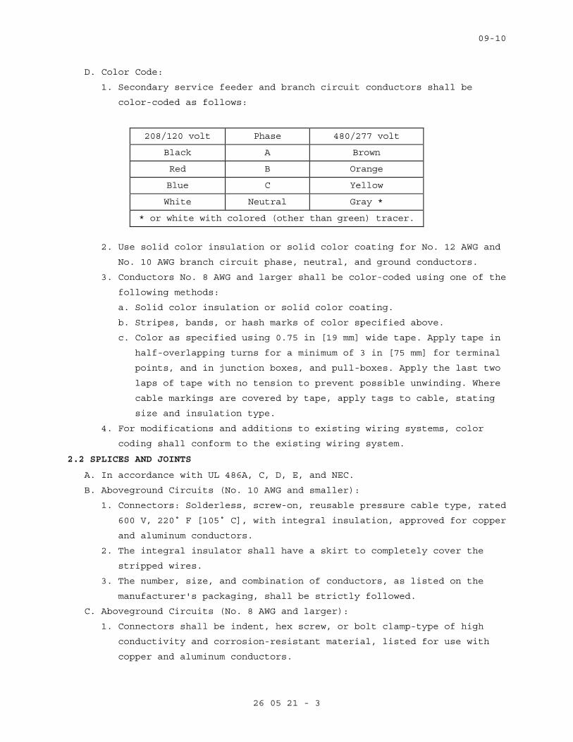
09-10
26 05 21 - 3
D. Color Code:
1. Secondary service feeder and branch circuit conductors shall be
color-coded as follows:
208/120 volt Phase 480/277 volt
Black A Brown
Red B Orange
Blue C Yellow
White Neutral Gray *
* or white with colored (other than green) tracer.
2. Use solid color insulation or solid color coating for No. 12 AWG and
No. 10 AWG branch circuit phase, neutral, and ground conductors.
3. Conductors No. 8 AWG and larger shall be color-coded using one of the
following methods:
a. Solid color insulation or solid color coating.
b. Stripes, bands, or hash marks of color specified above.
c. Color as specified using 0.75 in [19 mm] wide tape. Apply tape in
half-overlapping turns for a minimum of 3 in [75 mm] for terminal
points, and in junction boxes, and pull-boxes. Apply the last two
laps of tape with no tension to prevent possible unwinding. Where
cable markings are covered by tape, apply tags to cable, stating
size and insulation type.
4. For modifications and additions to existing wiring systems, color
coding shall conform to the existing wiring system.
2.2 SPLICES AND JOINTS
A. In accordance with UL 486A, C, D, E, and NEC.
B. Aboveground Circuits (No. 10 AWG and smaller):
1. Connectors: Solderless, screw-on, reusable pressure cable type, rated
600 V, 220˚ F [105˚ C], with integral insulation, approved for copper
and aluminum conductors.
2. The integral insulator shall have a skirt to completely cover the
stripped wires.
3. The number, size, and combination of conductors, as listed on the
manufacturer's packaging, shall be strictly followed.
C. Aboveground Circuits (No. 8 AWG and larger):
1. Connectors shall be indent, hex screw, or bolt clamp-type of high
conductivity and corrosion-resistant material, listed for use with
copper and aluminum conductors.
09-10
26 05 21 - 4
2. Field-installed compression connectors for cable sizes 250 kcmil and
larger shall have not fewer than two clamping elements or compression
indents per wire.
3. Insulate splices and joints with materials approved for the
particular use, location, voltage, and temperature. Splice and joint
insulation level shall be not less than the insulation level of the
conductors being joined.
4. Plastic electrical insulating tape: Per ASTM D2304, flame-retardant,
cold and weather resistant.
2.3 CONTROL WIRING
A. Unless otherwise specified elsewhere in these specifications, control
wiring shall be as specified for power and lighting wiring, except that
the minimum size shall be not less than No. 14 AWG.
B. Control wiring shall be large enough such that the voltage drop under
in-rush conditions does not adversely affect operation of the controls.
2.4 WIRE LUBRICATING COMPOUND
A. Lubricating compound shall be suitable for the wire insulation and
conduit, and shall not harden or become adhesive.
PART 3 - EXECUTION
3.1 GENERAL
A. Install in accordance with the NEC, and as specified.
B. Install all wiring in raceway systems.
C. Splice cables and wires only in outlet boxes, junction boxes, and pull-
boxes.
D. Wires of different systems (e.g., 120 V, 277 V) shall not be installed
in the same conduit or junction box system.
E. Install cable supports for all vertical feeders in accordance with the
NEC. Provide split wedge type which firmly clamps each individual cable
and tightens due to cable weight.
F. For panel boards, cabinets, wireways, switches, and equipment
assemblies, neatly form, train, and tie the cables in individual
circuits.
G. Seal cable and wire entering a building from underground between the
wire and conduit where the cable exits the conduit, with a non-hardening
approved compound.
H. Wire Pulling:
1. Provide installation equipment that will prevent the cutting or
abrasion of insulation during pulling of cables. Use lubricants
approved for the cable.
2. Use nonmetallic ropes for pulling feeders.
09-10
26 05 21 - 5
3. Attach pulling lines for feeders by means of either woven basket
grips or pulling eyes attached directly to the conductors, as
approved by the COR.
4. All cables in a single conduit shall be pulled simultaneously.
5. Do not exceed manufacturer’s recommended maximum pulling tensions and
sidewall pressure values.
I. No more than three single-phase branch circuits shall be installed in
any one conduit.
J. Conductor sizes indicated on the drawings are minimum sizes. Ampacities
of conductors do not take voltage drop into consideration. Contractor
shall size conductors for feeders and branch circuits to prevent a
voltage drop exceeding 3 percent at the farthest outlet of power,
heating, and lighting loads, or combination of such loads, and where the
maximum total voltage drop on both feeders and branch circuits to the
farthest outlet does not exceed 5 percent, to provide reasonable
efficiency of operation.
1. As a minimum, use 10 AWG conductor for 20 ampere, 120 volt branch
circuit home runs longer than 100 feet (30 m), and for 20 ampere, 277
volt branch circuit home runs longer than 200 feet (61 m).
3.2 SPLICE INSTALLATION
A. Splices and terminations shall be mechanically and electrically secure.
B. Tighten electrical connectors and terminals according to manufacturer's
published torque values.
C. Where the Government determines that unsatisfactory splices or
terminations have been installed, remove the devices and install
approved devices at no additional cost to the Government.
3.3 FEEDER IDENTIFICATION
A. In each interior pull-box and junction box, install metal tags on all
circuit cables and wires to clearly designate their circuit
identification and voltage. The tags shall be the embossed brass type,
1.5 in 3.4 existing wiring.
B. Unless specifically indicated on the plans, existing wiring shall not be
reused for a new installation.
3.5 CONTROL AND SIGNAL WIRING INSTALLATION
A. Unless otherwise specified in other sections, install wiring and connect
to equipment/devices to perform the required functions as shown and
specified.
B. Except where otherwise required, install a separate power supply circuit
for each system so that malfunctions in any system will not affect other
systems.
09-10
26 05 21 - 6
C. Where separate power supply circuits are not shown, connect the systems
to the nearest panel boards of suitable voltages, which are intended to
supply such systems and have suitable spare circuit breakers or space
for installation.
3.6 CONTROL AND SIGNAL SYSTEM WIRING IDENTIFICATION
A. Install a permanent wire marker on each wire at each termination.
B. Identifying numbers and letters on the wire markers shall correspond to
those on the wiring diagrams used for installing the systems.
C. Wire markers shall retain their markings after cleaning.
3.7 ACCEPTANCE CHECKS AND TESTS
A. Feeders and branch circuits shall have their insulation tested after
installation and before connection to utilization devices, such as
fixtures, motors, or appliances. Test each conductor with respect to
adjacent conductors and to ground.
B. Applied voltage shall be 500VDC for 300-volt rated cable, and 1000VDC
for 600-volt rated cable. Apply test for one minute or until reading is
constant for 15 seconds, whichever is longer. Minimum insulation
resistance values shall not be less than 25 megohms for 300-volt rated
cable and 100 megohms for 600-volt rated cable.
C. Perform phase rotation test on all three-phase circuits.
D. The contractor shall furnish the instruments, materials, and labor for
all tests.
- - - E N D - - -
09-10
26 05 26 - 1
SECTION 26 05 26 GROUNDING AND BONDING FOR ELECTRICAL SYSTEMS
PART 1 - GENERAL
1.1 DESCRIPTION
A. This section specifies the general grounding and bonding requirements
for electrical equipment and operations to provide a low impedance path
for possible ground fault currents.
B. “Grounding electrode system” refers to all electrodes required by NEC,
as well as made, supplementary, and lightning protection system
grounding electrodes.
C. The terms “connect” and “bond” are used interchangeably in this
specification and have the same meaning.
1.2 RELATED WORK
A. Section 26 05 11, REQUIREMENTS FOR ELECTRICAL INSTALLATIONS: General
electrical requirements and items that are common to more than one
section of Division 26.
B. Section 26 05 21, LOW-VOLTAGE ELECTRICAL POWER CONDUCTORS AND CABLES
(600 VOLTS AND BELOW): Low Voltage power and lighting wiring.
C. Section 26 24 16, PANELBOARDS: Low voltage panelboards.
1.3 QUALITY ASSURANCE
A. Refer to Paragraph, QUALIFICATIONS, in Section 26 05 11, REQUIREMENTS
FOR ELECTRICAL INSTALLATIONS.
1.4 SUBMITTALS
A. Submit in accordance with Section 26 05 11, REQUIREMENTS FOR ELECTRICAL
INSTALLATIONS.
B. Shop Drawings:
1. Clearly present enough information to determine compliance with
drawings and specifications.
2. Include the location of system grounding electrode connections and
the routing of aboveground and underground grounding electrode
conductors.
C. Test Reports: Provide certified test reports of ground resistance.
D. Certifications: Two weeks prior to final inspection, submit four copies
of the following to the COR:
1. Certification that the materials and installation are in accordance
with the drawings and specifications.
2. Certification by the contractor that the complete installation has
been properly installed and tested.
09-10
26 05 26 - 2
1.5 APPLICABLE PUBLICATIONS
A. Publications listed below (including amendments, addenda, revisions,
supplements, and errata) form a part of this specification to the
extent referenced. Publications are referenced in the text by
designation only.
American Society for Testing and Materials (ASTM):
B1-07...................Standard Specification for Hard-Drawn Copper
Wire
B3-07...................Standard Specification for Soft or Annealed
Copper Wire
B8-04...................Standard Specification for Concentric-Lay-
Stranded Copper Conductors, Hard, Medium-Hard,
or Soft
Institute of Electrical and Electronics Engineers, Inc. (IEEE):
81-1983.................IEEE Guide for Measuring Earth Resistivity,
Ground Impedance, and Earth Surface Potentials
of a Ground System
C2-07...................National Electrical Safety Code
National Fire Protection Association (NFPA):
70-08...................National Electrical Code (NEC)
99-2005.................Health Care Facilities
Underwriters Laboratories, Inc. (UL):
44-05 ..................Thermoset-Insulated Wires and Cables
83-08 ..................Thermoplastic-Insulated Wires and Cables
467-07 .................Grounding and Bonding Equipment
486A-486B-03 ...........Wire Connectors
PART 2 - PRODUCTS
2.1 GROUNDING AND BONDING CONDUCTORS
A. Equipment grounding conductors shall be UL 44 or UL 83 insulated
stranded copper, except that sizes No. 10 AWG [6 mm²] and smaller shall
be solid copper. Insulation color shall be continuous green for all
equipment grounding conductors, except that wire sizes No. 4 AWG [25
mm²] and larger shall be identified per NEC.
B. Bonding conductors shall be ASTM B8 bare stranded copper.
C. Conductor sizes shall not be less than shown on the drawings, or not
less than required by the NEC, whichever is greater.
09-10
26 05 26 - 3
2.2 GROUND CONNECTIONS
A. Above Grade:
1. Bonding Jumpers: Compression-type connectors, using zinc-plated
fasteners and external tooth lockwashers.
2. Connection to Building Steel: Exothermic-welded type connectors.
3. Ground Busbars: Two-hole compression type lugs, using tin-plated
copper or copper alloy bolts and nuts.
2.3 GROUND TERMINAL BLOCKS
A. At any equipment mounting location (e.g., backboards and hinged cover
enclosures) where rack-type ground bars cannot be mounted, provide
screw lug-type terminal blocks.
PART 3 - EXECUTION
3.1 GENERAL
A. Ground in accordance with the NEC, as shown on drawings, and as
specified herein.
B. System Grounding:
1. Secondary service neutrals: Ground at the supply side of the
secondary disconnecting C. Equipment Grounding: Metallic structures,
including ductwork and building steel, enclosures, raceways,
junction boxes, outlet boxes, cabinets, machine frames, and other
conductive items in close proximity with electrical circuits, shall
be bonded and grounded.
3.2 INACCESSIBLE GROUNDING CONNECTIONS
A. Make grounding connections, which are otherwise inaccessible (except
connections for which access for periodic testing is required), by
exothermic weld.
3.3 SECONDARY VOLTAGE EQUIPMENT AND CIRCUITS
A. Metallic Piping, Building Steel, and Supplemental Electrode(s):
1. Provide jumper insulating joints in the metallic piping. All
connections to electrodes shall be made with fittings that conform
to UL 467.
B. Panelboards:
1. Connect the various feeder equipment grounding conductors to the
ground bus in the enclosure with suitable pressure connectors.
3. Connect metallic conduits that terminate without mechanical
connection to the housing, by grounding bushings and grounding
conductor to the equipment ground bus.
09-10
26 05 26 - 4
3.5 RACEWAY
A. Conduit Systems:
1. Ground all metallic conduit systems. All metallic conduit systems
shall contain an equipment grounding conductor.
2. Conduit that only contains a grounding conductor, and is provided
for its mechanical protection, shall be bonded to that conductor at
the entrance and exit from the conduit.
3. Metallic conduits which terminate without mechanical connection to
an electrical equipment housing by means of locknut and bushings or
adapters, shall be provided with grounding bushings. Connect
bushings with a bare grounding conductor to the equipment ground
bus.
B. Branch Circuits: Install equipment grounding conductors with all
feeders and power and lighting branch circuits.
C. Boxes, Cabinets, Enclosures, and Panelboards:
1. Bond the equipment grounding conductor to each pullbox, junction
box, outlet box, device box, cabinets, and other enclosures through
which the conductor passes.
2. Provide lugs in each box and enclosure for equipment grounding
conductor termination.
D. Wireway Systems:
1. Bond the metallic structures of wireway to provide 100% electrical
continuity throughout the wireway system, by connecting a No. 6 AWG
[16 mm²] bonding jumper at all intermediate metallic enclosures and
across all section junctions.
2. Install insulated No. 6 AWG [16 mm²] bonding jumpers between the
wireway system, bonded as required above, and the closest building
ground at each end and approximately every 50 ft [16 M].
3. Use insulated No. 6 AWG [16 mm²] bonding jumpers to ground or bond
metallic wireway at each end for all intermediate metallic
enclosures and across all section junctions.
E. Receptacles shall not be grounded through their mounting screws. Ground
receptacles with a jumper from the receptacle green ground terminal to
the device box ground screw and a jumper to the branch circuit
equipment grounding conductor.
F. Fixed electrical appliances and equipment shall be provided with a
ground lug for termination of the equipment grounding conductor.
09-10
26 05 26 - 5
3.6 CORROSION INHIBITORS
A. When making ground and ground bonding connections, apply a corrosion
inhibitor to all contact surfaces. Use corrosion inhibitor appropriate
for protecting a connection between the metals used.
3.7 CONDUCTIVE PIPING
A. Bond all conductive piping systems, interior and exterior, to the
grounding electrode system. Bonding connections shall be made as close
as practical to the equipment ground bus.
3.8 GROUND RESISTANCE
A. Grounding system resistance to ground shall not exceed 5 ohms. Make any
modifications or additions to the grounding electrode system necessary
for compliance without additional cost to the Government. Final tests
shall ensure that this requirement is met.
B. Resistance of the grounding electrode system shall be measured using a
four-terminal fall-of-potential method as defined in IEEE 81. Ground
resistance measurements shall be made before the electrical
distribution system is energized and shall be made in normally dry
conditions not fewer than 48 hours after the last rainfall. Resistance
measurements of separate grounding electrode systems shall be made
before the systems are bonded together below grade. The combined
resistance of separate systems may be used to meet the required
resistance, but the specified number of electrodes must still be
provided.
- - - E N D - - -
09-10
26 05 33 - 1
SECTION 26 05 33 RACEWAY AND BOXES FOR ELECTRICAL SYSTEMS
PART 1 - GENERAL
1.1 DESCRIPTION
A. This section specifies the furnishing, installation, and connection of
conduit, fittings, and boxes, to form complete, coordinated, grounded
raceway systems. Raceways are required for all wiring unless shown or
specified otherwise.
B. Definitions: The term conduit, as used in this specification, shall mean
any or all of the raceway types specified.
1.2 RELATED WORK
A. Section 06 10 00, ROUGH CARPENTRY: Mounting board for telephone closets.
B. Section 07 84 00, FIRESTOPPING: Sealing around penetrations to maintain
the integrity of fire rated construction.
C. Section 09 91 00, PAINTING: Identification and painting of conduit and
other devices.
D. Section 26 05 11, REQUIREMENTS FOR ELECTRICAL INSTALLATIONS: General
electrical requirements and items that are common to more than one
section of Division 26.
E. Section 26 05 26, GROUNDING AND BONDING FOR ELECTRICAL SYSTEMS:
Requirements for personnel safety and to provide a low impedance path
for possible ground fault currents.
1.3 QUALITY ASSURANCE
A. Refer to Paragraph, QUALIFICATIONS, in Section 26 05 11, REQUIREMENTS
FOR ELECTRICAL INSTALLATIONS.
1.4 SUBMITTALS
A. In accordance with Section 26 05 11, REQUIREMENTS FOR ELECTRICAL
INSTALLATIONS, submit the following:
1. Manufacturer's Literature and Data: Showing each cable type and
rating. The specific item proposed and its area of application shall
be identified on the catalog cuts.
2. Shop Drawings:
a. Size and location of main feeders.
b. Size and location of panels and pull-boxes.
c. Layout of required conduit penetrations through structural
elements.
3. Certifications:
a. Two weeks prior to the final inspection, submit four copies of the
following certifications to the COR:
09-10
26 05 33 - 2
i. Certification by the manufacturer that the material conforms to
the requirements of the drawings and specifications.
ii. Certification by the contractor that the material has been
properly installed.
1.5 APPLICABLE PUBLICATIONS
A. Publications listed below (including amendments, addenda, revisions,
supplements, and errata) form a part of this specification to the extent
referenced. Publications are referenced in the text by designation only.
B. American National Standards Institute (ANSI):
C80.3-05................Steel Electrical Metal Tubing
C. National Fire Protection Association (NFPA):
70-08...................National Electrical Code (NEC)
D. Underwriters Laboratories, Inc. (UL):
1-05....................Flexible Metal Conduit
5-04....................Surface Metal Raceway and Fittings
50-95...................Enclosures for Electrical Equipment
467-07..................Grounding and Bonding Equipment
514A-04.................Metallic Outlet Boxes
514B-04.................Conduit, Tubing, and Cable Fittings
797-07..................Electrical Metallic Tubing
E. National Electrical Manufacturers Association (NEMA):
FB1-07..................Fittings, Cast Metal Boxes and Conduit Bodies
for Conduit, Electrical Metallic Tubing and
Cable
PART 2 - PRODUCTS
2.1 MATERIAL
A. Conduit Size: In accordance with the NEC, but not less than 0.5 in [13
mm] unless otherwise shown. Where permitted by the NEC, 0.5 in [13 mm]
flexible conduit may be used for tap connections to recessed lighting
fixtures.
B. Conduit:
1. Electrical metallic tubing (EMT): Shall conform to UL 797 and ANSI
C80.3. Maximum size not to exceed 4 in [105 mm] and shall be
permitted only with cable rated 600 V or less.
2. Flexible galvanized steel conduit: Shall conform to UL 1.
3. Surface metal raceway: Shall conform to UL 5.
C. Conduit Fittings:
1. Electrical metallic tubing fittings:
a. Fittings and conduit bodies shall meet the requirements of UL
514B, ANSI C80.3, and NEMA FB1.

09-10
26 05 33 - 3
b. Only steel or malleable iron materials are acceptable.
c. Compression couplings and connectors: Concrete-tight and rain-
tight, with connectors having insulated throats.
d. Indent-type connectors or couplings are prohibited.
e. Die-cast or pressure-cast zinc-alloy fittings or fittings made of
"pot metal" are prohibited.
2. Flexible steel conduit fittings:
a. Conform to UL 514B. Only steel or malleable iron materials are
acceptable.
b. Clamp-type, with insulated throat.
3. Liquid-tight flexible metal conduit fittings:
a. Fittings shall meet the requirements of UL 514B and NEMA FB1.
b. Only steel or malleable iron materials are acceptable.
c. Fittings must incorporate a threaded grounding cone, a steel or
plastic compression ring, and a gland for tightening. Connectors
shall have insulated throats.
4. Surface metal raceway fittings: As recommended by the raceway
manufacturer. Include couplings, offsets, elbows, expansion joints,
adapters, hold-down straps, end caps, conduit entry fittings,
accessories, and other fittings as required for complete system.
Fittings shall be stainless steel.
5. Expansion and deflection couplings:
a. Conform to UL 467 and UL 514B.
b. Accommodate a 0.75 in [19 mm] deflection, expansion, or
contraction in any direction, and allow 30 degree angular
deflections.
c. Include internal flexible metal braid, sized to guarantee conduit
ground continuity and a low-impedance path for fault currents, in
accordance with UL 467 and the NEC tables for equipment grounding
conductors.
d. Jacket: Flexible, corrosion-resistant, watertight, moisture and
heat-resistant molded rubber material with stainless steel jacket
clamps.
D. Conduit Supports:
1. Parts and hardware: Zinc-coat or provide equivalent corrosion
protection.
2. Individual Conduit Hangers: Designed for the purpose, having a
pre-assembled closure bolt and nut, and provisions for receiving a
hanger rod.
09-10
26 05 33 - 4
3. Multiple conduit (trapeze) hangers: Not less than 1.5 x 1.5 in [38 mm
x 38 mm], 12-gauge steel, cold-formed, lipped channels; with not less
than 0.375 in [9 mm] diameter steel hanger rods.
4. Solid Masonry and Concrete Anchors: Self-drilling expansion shields,
or machine bolt expansion.
E. Outlet, Junction, and Pull Boxes:
1. UL-50 and UL-514A.
2. Cast metal where required by the NEC or shown, and equipped with
rustproof boxes.
3. Sheet metal boxes: Galvanized steel, except where otherwise shown.
4. Flush-mounted wall or ceiling boxes shall be installed with raised
covers so that the front face of raised cover is flush with the wall.
Surface-mounted wall or ceiling boxes shall be installed with
surface-style flat or raised covers.
F. Wireways: Equip with hinged covers, except where removable covers are shown. Include couplings, offsets, elbows, expansion joints, adapters,
hold-down straps, end caps, and other fittings to match and mate with
wireways as required for a complete system.
PART 3 - EXECUTION
3.1 PENETRATIONS
A. Cutting or Holes:
1. Cut holes in advance where they should be placed in the structural
elements, such as ribs or beams. Obtain the approval of the COR prior
to drilling through structural elements.
2. Cut holes through concrete and masonry in new and existing structures
with a diamond core drill or concrete saw. Pneumatic hammers, impact
electric, hand, or manual hammer-type drills are not allowed, except
where permitted by the COR as required by limited working space.
B. Firestop: Where conduits, wireways, and other electrical raceways pass
through fire partitions, fire walls, smoke partitions, or floors,
install a fire stop that provides an effective barrier against the
spread of fire, smoke and gases as specified in Section 07 84 00,
FIRESTOPPING.
3.2 INSTALLATION, GENERAL
A. In accordance with UL, NEC, as shown, and as specified herein.
B. Essential (Emergency) raceway systems shall be entirely independent of
other raceway systems, except where shown on drawings.
C. Install conduit as follows:
1. In complete mechanically and electrically continuous runs before
pulling in cables or wires.
09-10
26 05 33 - 5
2. Unless otherwise indicated on the drawings or specified herein,
installation of all conduits shall be concealed within finished
walls, floors, and ceilings.
3. Flattened, dented, or deformed conduit is not permitted. Remove and
replace the damaged conduits with new undamaged material.
4. Assure conduit installation does not encroach into the ceiling height
head room, walkways, or doorways.
5. Cut square, ream, remove burrs, and draw up tight.
6. Independently support conduit at 8 ft [2.4 M] on centers. Do not use
other supports, i.e., suspended ceilings, suspended ceiling
supporting members, lighting fixtures, conduits, mechanical piping,
or mechanical ducts.
7. Support within 12 in [300 mm] of changes of direction, and within 12
in [300 mm] of each enclosure to which connected.
8. Close ends of empty conduit with plugs or caps at the rough-in stage
until wires are pulled in, to prevent entry of debris.
9. Conduit installations under fume and vent hoods are prohibited.
10. Secure conduits to cabinets, junction boxes, pull-boxes, and outlet
boxes with bonding type locknuts. For rigid and IMC conduit
installations, provide a locknut on the inside of the enclosure, made
up wrench tight. Do not make conduit connections to junction box
covers.
11. Flashing of penetrations of the roof membrane is specified in Section
07 60 00, FLASHING AND SHEET METAL.
12. Conduit bodies shall only be used for changes in direction, and shall
not contain splices.
D. Conduit Bends:
1. Make bends with standard conduit bending machines.
2. Conduit hickey may be used for slight offsets and for straightening
stubbed out conduits.
3. Bending of conduits with a pipe tee or vise is prohibited.
E. Layout and Homeruns:
1. Install conduit with wiring, including homeruns, as shown on
drawings.
2. Deviations: Make only where necessary to avoid interferences and only
after drawings showing the proposed deviations have been submitted
approved by the COR.
3.3 CONCEALED WORK INSTALLATION
A. Above Furred or Suspended Ceilings and in Walls:
1. Conduit for conductors 600 V and below: EMT.
09-10
26 05 33 - 6
2. Align and run conduit parallel or perpendicular to the building
lines.
3. Tightening setscrews with pliers is prohibited.
3.4 EXPOSED WORK INSTALLATION
A. Unless otherwise indicated on the drawings, exposed conduit is only
permitted in mechanical and electrical rooms.
B. Conduit for Conductors 600 V and Below: EMT. Mixing different types of
conduits indiscriminately in the system is prohibited.
C. Align and run conduit parallel or perpendicular to the building lines.
D. Install horizontal runs close to the ceiling or beams and secure with
conduit straps.
E. Support horizontal or vertical runs at not over 8 ft [2.4 M] intervals.
F. Surface metal raceways: Use only where shown.
G. Painting:
1. Paint exposed conduit as specified in Section 09 91 00, PAINTING.
3.5 WET OR DAMP LOCATIONS
A. Unless otherwise shown, use conduits of rigid steel or IMC.
3.6 MOTORS AND VIBRATING EQUIPMENT
A. Use flexible metal conduit for connections to motors and other
electrical equipment subject to movement, vibration, misalignment,
cramped quarters, or noise transmission.
B. Use liquid-tight flexible metal conduit for installation in exterior
locations, moisture or humidity laden atmosphere, and inside airstream
of HVAC units. Provide a green equipment grounding conductor with
flexible metal conduit.
3.7 CONDUIT SUPPORTS, INSTALLATION
A. Safe working load shall not exceed one-quarter of proof test load of
fastening devices.
B. Use pipe straps or individual conduit hangers for supporting individual
conduits.
C. Support multiple conduit runs with trapeze hangers. Use trapeze hangers
that are designed to support a load equal to or greater than the sum of
the weights of the conduits, wires, hanger itself, and 200 lbs [90 kg].
Attach each conduit with U-bolts or other approved fasteners.
D. Support conduit independently of junction boxes, pull-boxes, fixtures,
suspended ceiling T-bars, angle supports, and similar items.
E. Fasteners and Supports in Solid Masonry and Concrete:
1. Existing Construction:
a. Steel expansion anchors not less than 0.25 in [6 mm] bolt size and
not less than 1.125 in [28 mm] embedment.
09-10
26 05 33 - 7
b. Power set fasteners not less than 0.25 in [6 mm] diameter with
depth of penetration not less than 3 in [75 mm].
c. Use vibration and shock-resistant anchors and fasteners for
attaching to concrete ceilings.
F. Hollow Masonry: Toggle bolts.
G. Bolts supported only by plaster or gypsum wallboard are not acceptable.
H. Metal Structures: Use machine screw fasteners or other devices
specifically designed and approved for the application.
I. Attachment by wood plugs, rawl plug, plastic, lead or soft metal
anchors, or wood blocking and bolts supported only by plaster is
prohibited.
J. Chain, wire, or perforated strap shall not be used to support or fasten
conduit.
K. Spring steel type supports or fasteners are prohibited for all uses
except horizontal and vertical supports/fasteners within walls.
L. Vertical Supports: Vertical conduit runs shall have riser clamps and
supports in accordance with the NEC and as shown. Provide supports for
cable and wire with fittings that include internal wedges and retaining
collars.
3.8 BOX INSTALLATION
A. Boxes for Concealed Conduits:
1. Flush-mounted.
2. Provide raised covers for boxes to suit the wall or ceiling,
construction, and finish.
B. In addition to boxes shown, install additional boxes where needed to
prevent damage to cables and wires during pulling-in operations.
C. Remove only knockouts as required and plug unused openings. Use threaded
plugs for cast metal boxes and snap-in metal covers for sheet metal
boxes.
D. Outlet boxes mounted back-to-back in the same wall are prohibited. A
minimum 24 in [600 mm] center-to-center lateral spacing shall be
maintained between boxes.
E. Minimum size of outlet boxes for ground fault interrupter (GFI)
receptacles is 4 in [100 mm] square x 2.125 in [55 mm] deep, with device
covers for the wall material and thickness involved.
F. Stencil or install phenolic nameplates on covers of the boxes identified
on riser diagrams; for example "SIG-FA JB No. 1."
G. On all branch circuit junction box covers, identify the circuits with
black marker.
- - - E N D - - -

09-10
26 24 16 - 1
SECTION 26 24 16 PANELBOARDS
PART 1 - GENERAL
1.1 DESCRIPTION
A. This section specifies the furnishing, installation, and connection of
panelboards.
1.2 RELATED WORK
A. Section 09 91 00, PAINTING: Identification and painting of panelboards.
B. Section 26 05 11, REQUIREMENTS FOR ELECTRICAL INSTALLATIONS: General
electrical requirements and items that are common to more than one
Section of Division 26.
C. Section 26 05 21, LOW-VOLTAGE ELECTRICAL POWER CONDUCTORS AND CABLES
(600 VOLTS AND BELOW): Cables and wiring.
D. Section 26 05 26, GROUNDING AND BONDING FOR ELECTRICAL SYSTEMS:
Requirements for personnel safety and to provide a low impedance path
for possible ground fault currents.
E. Section 26 05 33, RACEWAY AND BOXES FOR ELECTRICAL SYSTEMS: Conduits
and outlet boxes.
1.3 QUALITY ASSURANCE
A. Refer to Paragraph, QUALIFICATIONS, in Section 26 05 11, REQUIREMENTS
FOR ELECTRICAL INSTALLATIONS.
1.4 SUBMITTALS
A. Submit in accordance with Section 26 05 11, REQUIREMENTS FOR ELECTRICAL
INSTALLATIONS.
B. Shop Drawings:
1. Sufficient information, shall be clearly presented to determine
compliance with drawings and specifications.
2. Include electrical ratings, dimensions, mounting details, materials,
wiring diagrams, accessories, and weights of equipment. Complete
nameplate data, including manufacturer’s name and catalog number.
C. Manuals:
1. When submitting the shop drawings, submit companion copies of
complete maintenance and operating manuals, including technical data
sheets and wiring diagrams.
2. If changes have been made to the maintenance and operating manuals
that were originally submitted, then submit four copies of updated
maintenance and operating manuals to the COR two weeks prior to
final inspection.
09-10
26 24 16 - 2
D. Certification: Two weeks prior to final inspection, submit four copies
of the following to the COR:
1. Certification by the manufacturer that the materials conform to the
requirements of the drawings and specifications.
2. Certification by the contractor that the materials have been
properly installed, connected, and tested.
1.5 APPLICABLE PUBLICATIONS
A. Publications listed below (including amendments, addenda, revisions,
supplements, and errata) form a part of this specification to the
extent referenced. Publications are referenced in the text by
designation only.
B. National Electrical Manufacturers Association (NEMA):
PB-1-06.................Panelboards
250-08..................Enclosures for Electrical Equipment (1000V
Maximum)
C. National Fire Protection Association (NFPA):
70-2005 ................National Electrical Code (NEC)
70E-2004................Standard for Electrical Life Safety in the
Workplace
D. Underwriters Laboratories, Inc. (UL):
50-95...................Enclosures for Electrical Equipment
67-09...................Panelboards
489-09..................Molded Case Circuit Breakers and Circuit
Breaker Enclosures
PART 2 - PRODUCTS
2.1 MOLDED CASE CIRCUIT BREAKERS FOR PANELBOARDS
A. Circuit breakers shall be per UL 489, in accordance with the NEC, as
shown on the drawings, and as specified.
B. Circuit breakers in panelboards shall be bolt-on type.
C. Molded case circuit breakers shall have minimum interrupting rating as
required to withstand the available fault current, but not less than:
1. 120/208 V Panelboard: 10,000 A symmetrical.
2. 120/240 V Panelboard: 10,000 A symmetrical.
3. 277/480 V Panelboard: 14,000 A symmetrical.
D. Molded case circuit breakers shall have automatic, trip free,
non-adjustable, inverse time, and instantaneous magnetic trips for 100
A frame or lower.
E. Breaker features shall be as follows:
09-10
26 24 16 - 3
1. A rugged, integral housing of molded insulating material.
2. Silver alloy contacts.
3. Arc quenchers and phase barriers for each pole.
4. Quick-make, quick-break, operating mechanisms.
5. A trip element for each pole, thermal magnetic type with long time
delay and instantaneous characteristics, a common trip bar for all
poles and a single operator.
6. Electrically and mechanically trip free.
7. An operating handle which indicates ON, TRIPPED, and OFF positions.
8. An overload on one pole of a multipole breaker shall automatically
cause all the poles of the breaker to open.
9. Ground fault current interrupting breakers, shunt trip breakers,
lighting control breakers (including accessories to switch line
currents), or other accessory devices or functions shall be provided
where indicated.
10. For circuit breakers being added to existing panelboards, coordinate
the breaker type with existing panelboards. Modify the panel
directory accordingly.
PART 3 - EXECUTION
3.1 INSTALLATION
A. Installation shall be in accordance with the manufacturer’s
instructions, the NEC, as shown on the drawings, and as specified.
B. Install a printed schedule of circuits in each panelboard after
approval by the COR. Schedules shall be printed on the panelboard
directory cards, installed in the appropriate panelboards, and
incorporate all applicable contract changes. Information shall indicate
outlets, lights, devices, or other equipment controlled by each
circuit, and the final room numbers served by each circuit.
3.2 ACCEPTANCE CHECKS AND TESTS
A. Perform in accordance with the manufacturer's recommendations. Include
the following visual and mechanical inspections and electrical tests:
1. Visual and Mechanical Inspection
a. Compare equipment nameplate data with specifications and approved
shop drawings.
b. Inspect physical, electrical, and mechanical condition.
c. Verify appropriate anchorage and required area clearances.
d. Verify that circuit breaker sizes and types correspond to
approved shop drawings.
09-10
26 24 16 - 4
e. To verify tightness of accessible bolted electrical connections,
use the calibrated torque-wrench method or perform thermographic
survey after energization.
f. Clean panelboard.
3.3 FOLLOW-UP VERIFICATION
A. Upon completion of acceptance checks, settings, and tests, the
contractor shall demonstrate that the panelboards are in good operating
condition and properly performing the intended function.
- - - E N D - - -
4-09
26 27 26 - 1
SECTION 26 27 26 WIRING DEVICES
PART 1 - GENERAL
1.1 DESCRIPTION
A. This section specifies the furnishing, installation and connection of
wiring devices.
1.2 RELATED WORK
A. Section 26 05 11, REQUIREMENTS FOR ELECTRICAL INSTALLATIONS: General
electrical requirements that are common to more than one section of
Division 26.
B. Section 26 05 33, RACEWAY AND BOXES FOR ELECTRICAL SYSTEMS: Conduits and
outlets boxes.
C. Section 26 05 21, LOW-VOLTAGE ELECTRICAL POWER CONDUCTORS AND CABLES
(600 VOLTS AND BELOW): Cables and wiring.
D. Section 26 05 26, GROUNDING AND BONDING FOR ELECTRICAL SYSTEMS:
Requirements for personnel safety and to provide a low impedance path to
ground for possible ground fault currents.
1.3 QUALITY ASSURANCE
A. Refer to Paragraph, QUALIFICATIONS, in Section 26 05 11, REQUIREMENTS
FOR ELECTRICAL INSTALLATIONS.
1.4 SUBMITTALS
A. In accordance with Section 26 05 11, REQUIREMENTS FOR ELECTRICAL
INSTALLATIONS, submit the following:
B. Shop Drawings:
1. Sufficient information, clearly presented, shall be included to
determine compliance with drawings and specifications.
2. Include electrical ratings, dimensions, mounting details,
construction materials, grade and termination information.
C. Manuals: Two weeks prior to final inspection, deliver four copies of the
following to the Project Engineer: Technical data sheets and information
for ordering replacement units.
D. Certifications: Two weeks prior to final inspection, submit four copies
of the following to the Project Engineer: Certification by the
Contractor that the devices comply with the drawings and specifications,
and have been properly installed, aligned, and tested.
1.5 APPLICABLE PUBLICATIONS
A. Publications listed below (including amendments, addenda, revisions,
supplements and errata) form a part of this specification to the extent
4-09
26 27 26 - 2
referenced. Publications are referenced in the text by basic designation
only.
B. National Fire Protection Association (NFPA):
70......................National Electrical Code (NEC)
C. National Electrical Manufacturers Association (NEMA):
WD 1....................General Color Requirements for Wiring Devices
WD 6 ...................Wiring Devices – Dimensional Requirements
D. Underwriter’s Laboratories, Inc. (UL):
5.......................Surface Metal Raceways and Fittings
20......................General-Use Snap Switches
231.....................Power Outlets
467.....................Grounding and Bonding Equipment
498.....................Attachment Plugs and Receptacles
943.....................Ground-Fault Circuit-Interrupters
PART 2 - PRODUCTS
2.1 RECEPTACLES
A. General: All receptacles shall be listed by Underwriters Laboratories,
Inc., and conform to NEMA WD 6.
1. Mounting straps shall be plated steel, with break-off plaster ears
and shall include a self-grounding feature. Terminal screws shall be
brass, brass plated or a copper alloy metal.
2. Receptacles shall have provisions for back wiring with separate metal
clamp type terminals (four min.) and side wiring from four captively
held binding screws.
B. Duplex Receptacles: Hospital-grade, single phase, 20 ampere, 120 volts,
2-pole, 3-wire, and conform to the NEMA 5-20R configuration in NEMA WD
6. The duplex type shall have break-off feature for two-circuit
operation. The ungrounded pole of each receptacle shall be provided with
a separate terminal.
1. Bodies shall be ivory in color.
2. Ground Fault Interrupter Duplex Receptacles: Shall be an integral
unit, hospital-grade, suitable for mounting in a standard outlet box.
a. Ground fault interrupter shall be consist of a differential
current transformer, solid state sensing circuitry and a circuit
interrupter switch. Device shall have nominal sensitivity to
ground leakage current of five milliamperes and shall function to
interrupt the current supply for any value of ground leakage
current above five milliamperes (+ or – 1 milliamp) on the load
side of the device. Device shall have a minimum nominal tripping
time of 1/30th of a second.
4-09
26 27 26 - 3
C. Receptacles; 20, 30 and 50 ampere, 250 volts: Shall be complete with
appropriate cord grip plug. Devices shall meet UL 231.
2.4 WALL PLATES
A. Wall plates for switches and receptacles shall be type smooth nylon.
Oversize plates are not acceptable.
B. Color shall be ivory unless otherwise specified.
C. Standard NEMA design, so that products of different manufacturers will
be interchangeable. Dimensions for openings in wall plates shall be
accordance with NEMA WD 6.
D. For receptacles mounted adjacent to each other, wall plates shall be
common for each group.
E. Wall plates for data, telephone or other communication outlets shall be
as specified in the associated specification.
F. Duplex Receptacles on Emergency Circuit:
1. Bodies shall be red in color. Wall plates shall be red with the word
"EMERGENCY" engraved in 6 mm, (1/4 inch) white letters.
PART 3 - EXECUTION
3.1 INSTALLATION
A. Installation shall be in accordance with the NEC and as shown as on the
drawings.
B. Ground terminal of each receptacle shall be bonded to the outlet box
with an approved green bonding jumper, and also connected to the green
equipment grounding conductor.
C. Provide barriers in multigang outlet boxes to separate systems of
different voltages, Normal Power and Emergency Power systems, and in
compliance with the NEC.
D. Coordinate with other work, including painting, electrical boxes and
wiring installations, as necessary to interface installation of wiring
devices with other work. Coordinate the electrical work with the work
of other trades to ensure that wiring device flush outlets are positioned
with box openings aligned with the face of the surrounding finish
material.
E. Exact field locations of floors, walls, partitions, doors, windows, and
equipment may vary from locations shown on the drawings. Prior to
locating sleeves, boxes and chases for roughing-in of conduit and
equipment, the Contractor shall coordinate exact field location of the
above items with other trades. In addition, check for exact direction of
door swings so that local switches are properly located on the strike
side.
4-09
26 27 26 - 4
F. Install convenience receptacles 18 inches [450mm] above floor, and 6
inches [152mm] above counter backsplash or workbenches. Install
specific-use receptacles at heights shown on the drawings.
G. Label device plates with a permanent adhesive label listing panel and
circuit feeding the wiring device.
H. Test wiring devices for damaged conductors, high circuit resistance,
poor connections, inadequate fault current path, defective devices, or
similar problems using a portable receptacle tester. Correct circuit
conditions, remove malfunctioning units and replace with new, and retest
as specified above.
- - - E N D - - -
11-09
27 05 11 - 1
SECTION 27 05 11 REQUIREMENTS FOR COMMUNICATIONS INSTALLATIONS
PART 1 - GENERAL
1.1 DESCRIPTION
A. This Section, Requirements for Communications Installations, applies to
all sections of Division 27.
B. Furnish and install communications cabling, systems, equipment, and
accessories in accordance with the specifications and drawings.
Capacities and ratings of transformers, cable, and other items and
arrangements for the specified items are shown on drawings.
1.2 MINIMUM REQUIREMENTS
A. References to industry and trade association standards and codes are
minimum installation requirement standards.
B. Drawings and other specification sections shall govern in those
instances where requirements are greater than those specified in the
above standards.
1.3 QUALIFICATIONS (PRODUCTS AND SERVICES)
A. Manufacturers Qualifications: The manufacturer shall regularly and
presently produce, as one of the manufacturer's principal products, the
equipment and material specified for this project, and shall have
manufactured the item for at least three years.
B. Product Qualification:
1. Manufacturer's product shall have been in satisfactory operation, on
three installations of similar size and type as this project, for
approximately three years.
2. The Government reserves the right to require the Contractor to submit
a list of installations where the products have been in operation
before approval.
C. Service Qualifications: There shall be a permanent service organization
maintained or trained by the manufacturer which will render satisfactory
service to this installation within four hours of receipt of
notification that service is needed. Submit name and address of service
organizations.
1.4 MANUFACTURED PRODUCTS
A. Materials and equipment furnished shall be of current production by
manufacturers regularly engaged in the manufacture of such items, for
which replacement parts shall be available.
B. When more than one unit of the same class of equipment is required, such
units shall be the product of a single manufacturer.
11-09
27 05 11 - 2
C. Equipment Assemblies and Components:
1. Components of an assembled unit need not be products of the same
manufacturer.
2. Manufacturers of equipment assemblies, which include components made
by others, shall assume complete responsibility for the final
assembled unit.
3. Components shall be compatible with each other and with the total
assembly for the intended service.
4. Constituent parts which are similar shall be the product of a single
manufacturer.
D. Factory wiring shall be identified on the equipment being furnished and
on all wiring diagrams.
E. When Factory Testing Is Specified:
1. The Government shall have the option of witnessing factory tests. The
contractor shall notify the VA through the COR a minimum of 15
working days prior to the manufacturers making the factory tests.
2. Four copies of certified test reports containing all test data shall
be furnished to the COR prior to final inspection and not more than
90 days after completion of the tests.
3. When equipment fails to meet factory test and re-inspection is
required, the contractor shall be liable for all additional expenses,
including expenses of the Government.
1.5 EQUIPMENT REQUIREMENTS
A. Where variations from the contract requirements are requested in
accordance with the GENERAL CONDITIONS and Section 01 33 23, SHOP
DRAWINGS, PRODUCT DATA, AND SAMPLES, the connecting work and related
components shall include, but not be limited to additions or changes to
branch circuits, circuit protective devices, conduits, wire, feeders,
controls, panels and installation methods.
1.6 EQUIPMENT PROTECTION
A. Equipment and materials shall be protected during shipment and storage
against physical damage, dirt, moisture, cold and rain:
1. During installation, enclosures, equipment, controls, controllers,
circuit protective devices, and other like items, shall be protected
against entry of foreign matter; and be vacuum cleaned both inside
and outside before testing and operating and repainting if required.
2. Damaged equipment shall be, as determined by the COR, placed in first
class operating condition or be returned to the source of supply for
repair or replacement.

11-09
27 05 11 - 3
3. Painted surfaces shall be protected with factory installed removable
heavy kraft paper, sheet vinyl or equal.
4. Damaged paint on equipment and materials shall be refinished with the
same quality of paint and workmanship as used by the manufacturer so
repaired areas are not obvious.
1.7 WORK PERFORMANCE
A. Job site safety and worker safety is the responsibility of the
contractor.
B. For work on existing stations, arrange, phase and perform work to assure
communications service for other buildings at all times. Refer to
Article OPERATIONS AND STORAGE AREAS under Section 01 00 00, GENERAL
REQUIREMENTS.
C. New work shall be installed and connected to existing work neatly and
carefully. Disturbed or damaged work shall be replaced or repaired to
its prior conditions, as required by Section 01 00 00, GENERAL
REQUIREMENTS.
D. Coordinate location of equipment and pathways with other trades to
minimize interferences. See the GENERAL CONDITIONS.
1.8 EQUIPMENT INSTALLATION AND REQUIREMENTS
A. Equipment location shall be as close as practical to locations shown on
the drawings.
B. Inaccessible Equipment:
1. Where the Government determines that the Contractor has installed
equipment not conveniently accessible for operation and maintenance,
the equipment shall be removed and reinstalled as directed at no
additional cost to the Government.
2. "Conveniently accessible" is defined as being capable of being
reached without the use of ladders, or without climbing or crawling
under or over obstacles such as, but not limited to, motors, pumps,
belt guards, transformers, piping, ductwork, conduit and raceways.
1.9 EQUIPMENT IDENTIFICATION
A. Install an identification sign which clearly indicates information
required for use and maintenance of equipment.
B. Nameplates shall be laminated black phenolic resin with a white core
with engraved lettering, a minimum of 6 mm (1/4 inch) high. Secure
nameplates with screws. Nameplates that are furnished by manufacturer as
a standard catalog item, or where other method of identification is
herein specified, are exceptions.
11-09
27 05 11 - 4
1.10 SUBMITTALS
A. Submit in accordance with Section 01 33 23, SHOP DRAWINGS, PRODUCT DATA,
AND SAMPLES.
B. The Government's approval shall be obtained for all equipment and
material before delivery to the job site. Delivery, storage, or
installation of equipment or material which has not had prior approval
will not be permitted at the job site.
C. All submittals shall include adequate descriptive literature, catalog
cuts, shop drawings, and other data necessary for the Government to
ascertain that the proposed equipment and materials comply with
specification requirements. Catalog cuts submitted for approval shall
be legible and clearly identify equipment being submitted.
D. Submittals for individual systems and equipment assemblies which consist
of more than one item or component shall be made for the system or
assembly as a whole. Partial submittals will not be considered for
approval.
1. Mark the submittals, "SUBMITTED UNDER SECTION__________________".
2. Submittals shall be marked to show specification reference including
the section and paragraph numbers.
3. Submit each section separately.
E. The submittals shall include the following:
1. Information that confirms compliance with contract requirements.
Include the manufacturer's name, model or catalog numbers, catalog
information, technical data sheets, shop drawings, pictures,
nameplate data and test reports as required.
2. Elementary and interconnection wiring diagrams for communication and
signal systems, control system and equipment assemblies. All terminal
points and wiring shall be identified on wiring diagrams.
3. Parts list which shall include those replacement parts recommended by
the equipment manufacturer, quantity of parts, current price and
availability of each part.
F. Manuals: Submit in accordance with Section 01 00 00, GENERAL
REQUIREMENTS.
1. Maintenance and Operation Manuals: Submit as required for systems and
equipment specified in the technical sections. Furnish four copies,
bound in hardback binders, (manufacturer's standard binders) or an
approved equivalent. Furnish one complete manual as specified in the
technical section but in no case later than prior to performance of
systems or equipment test, and furnish the remaining manuals prior to
contract completion.

11-09
27 05 11 - 5
2. Inscribe the following identification on the cover: the words
"MAINTENANCE AND OPERATION MANUAL," the name and location of the
system, equipment, building, name of Contractor, and contract number.
Include in the manual the names, addresses, and telephone numbers of
each subcontractor installing the system or equipment and the local
representatives for the system or equipment.
3. Provide a "Table of Contents" and assemble the manual to conform to
the table of contents, with tab sheets placed before instructions
covering the subject. The instructions shall be legible and easily
read, with large sheets of drawings folded in.
4. The manuals shall include:
a. Internal and interconnecting wiring and control diagrams with data
to explain detailed operation and control of the equipment.
b. A control sequence describing start-up, operation, and shutdown.
c. Description of the function of each principal item of equipment.
d. Installation and maintenance instructions.
e. Safety precautions.
f. Diagrams and illustrations.
g. Testing methods.
h. Performance data.
i. Pictorial "exploded" parts list with part numbers. Emphasis shall
be placed on the use of special tools and instruments. The list
shall indicate sources of supply, recommended spare parts, and
name of servicing organization.
j. Appendix; list qualified permanent servicing organizations for
support of the equipment, including addresses and certified
qualifications.
G. Approvals will be based on complete submission of manuals together with
shop drawings.
1.11 SINGULAR NUMBER
A. Where any device or part of equipment is referred to in these
specifications in the singular number (e.g., "the switch"), this
reference shall be deemed to apply to as many such devices as are
required to complete the installation as shown on the drawings.
1.12 TRAINING
A. Training shall be provided in accordance with Article, INSTRUCTIONS, of
Section 01 00 00, GENERAL REQUIREMENTS.
B. Training shall be provided for the particular equipment or system as
required in each associated specification.

11-09
27 05 11 - 6
C. A training schedule shall be developed and submitted by the contractor
and approved by the COR at least 30 days prior to the planned training.
- - - E N D - - -
10-06M
27 05 26 - 1
SECTION 27 05 26 GROUNDING AND BONDING FOR COMMUNICATIONS SYSTEMS
PART 1 - GENERAL
1.1 DESCRIPTION
A. This section specifies general grounding and bonding requirements of
telecommunication installations for equipment operations.
B. “Grounding electrode system” refers to all electrodes required by NEC,
as well as including made, supplementary, telecommunications system
grounding electrodes.
C. The terms “connect” and “bond” are used interchangeably in this
specification and have the same meaning.
1.2 RELATED WORK
A. Section 27 05 11, REQUIREMENTS FOR COMMUNICATIONS INSTALLATIONS:
General electrical requirements and items that is common to more than
one section of Division 27.
B. Section 27 10 00, STRUCTURED CABLING: Low Voltage power wiring.
1.3 SUBMITTALS
A. Submit in accordance with Section 27 05 11, REQUIREMENTS FOR
COMMUNICATIONS INSTALLATIONS.
B. Shop Drawings:
1. Sufficient information, clearly presented, shall be included to
determine compliance with drawings and specifications.
2. Include the location of system grounding electrode connections and
the routing of grounding electrode conductors.
C. Test Reports: Provide certified test reports of ground resistance.
D. Certifications: Two weeks prior to final inspection, submit four copies
of the following to the COR:
1. Certification that the materials and installation is in accordance
with the drawings and specifications.
2. Certification, by the Contractor, that the complete installation has
been properly installed and tested.
1.4 APPLICABLE PUBLICATIONS
A. Publications listed below (including amendments, addenda, revisions,
supplements, and errata) form a part of this specification to the
extent referenced. Publications are referenced in the text by the basic
designation only.
B. American Society for Testing and Materials (ASTM):
10-06M
27 05 26 - 2
B1-2001.................Standard Specification for Hard-Drawn Copper
Wire
B8-2004.................Standard Specification for Concentric-Lay-
Stranded Copper Conductors, Hard, Medium-Hard,
or Soft
C. Institute of Electrical and Electronics Engineers, Inc. (IEEE):
81-1983.................IEEE Guide for Measuring Earth Resistivity,
Ground Impedance, and Earth Surface Potentials
of a Ground System
D. National Fire Protection Association (NFPA):
70-2005.................National Electrical Code (NEC)
E. Telecommunications Industry Association, (TIA)
J-STO-607-A-2002........Commercial Building Grounding (Earthing) and
Bonding Requirements for Telecommunications
F. Underwriters Laboratories, Inc. (UL):
44-2005 ................Thermoset-Insulated Wires and Cables
83-2003 ................Thermoplastic-Insulated Wires and Cables
467-2004 ...............Grounding and Bonding Equipment
486A-486B-2003 .........Wire Connectors
PART 2 - PRODUCTS
2.1 GROUNDING AND BONDING CONDUCTORS
A. Equipment grounding conductors shall be UL 83 insulated stranded
copper, except that sizes 6 mm² (10 AWG) and smaller shall be solid
copper. Insulation color shall be continuous green for all equipment
grounding conductors, except that wire sizes 25 mm² (4 AWG) and larger
shall be permitted to be identified per NEC.
B. Bonding conductors shall be ASTM B8 bare stranded copper, except that
sizes 6 mm² (10 AWG) and smaller shall be ASTM B1 solid bare copper
wire.
C. Isolated Power System: Type XHHW-2 insulation with a dielectric
constant of 3.5 or less.
D. Telecom System Grounding Riser Conductor: Telecommunications Grounding
Riser shall be in accordance with J STO-607A. Use a minimum 50mm² (1/0
AWG) insulated stranded copper grounding conductor unless indicated
otherwise.

10-06M
27 05 26 - 3
2.2 SPLICES AND TERMINATION COMPONENTS
A. Components shall meet or exceed UL 467 and be clearly marked with the
manufacturer, catalog number, and permitted conductor size(s).
2.3 TELECOMMUNICATION SYSTEM GROUND BUSBARS
A. Provide solid copper busbar, pre-drilled from two-hole lug connections
with a minimum thickness of 6 mm (1/4 inch) for wall and backboard
mounting using standard insulators sized as follows:
1. Room Signal Grounding: 300 mm x 100 mm (12 inches x 4 inch).
2. Master Signal Ground: 600 mm x 100 mm (24 inches x 4 inch).
2.4 GROUND CONNECTIONS
A. Above Grade:
1. Bonding Jumpers: compression type connectors, using zinc-plated
fasteners and external tooth lockwashers.
2. Ground Busbars: Two-hole compression type lugs using tin-plated
copper or copper alloy bolts and nuts.
3. Rack and Cabinet Ground Bars: one-hole compression-type lugs using
zinc-plated or copper alloy fasteners.
B. Cable Shields: Make ground connections to multipair communications
cables with metallic shields using shield bonding connectors with screw
stud connection 4 mm thick by 19 mm wide (3/8 inch x ¾ inch).
2.5 GROUND TERMINAL BLOCKS
A. At any equipment mounting location (e.g. backboards and hinged cover
enclosures) where rack-type ground bars cannot be mounted, provide
screw lug-type terminal blocks.
2.6 SPLICE CASE GROUND ACCESSORIES
A. Splice case grounding and bonding accessories shall be supplied by the
splice case manufacturer when available. Otherwise, use 16 mm² (6 AWG)
insulated ground wire with shield bonding connectors.
PART 3 - EXECUTION
3.1 GENERAL
A. Ground in accordance with the NEC, as shown on drawings, and as
hereinafter specified.
B. Equipment Grounding: Metallic structures (including ductwork and
building steel), enclosures, raceways, junction boxes, outlet boxes,
cabinets, machine frames, and other conductive items in close proximity
with electrical circuits shall be bonded and grounded.

10-06M
27 05 26 - 4
3.2 INACCESSIBLE GROUNDING CONNECTIONS
A. Make grounding connections, which are otherwise normally inaccessible
(except connections for which periodic testing access is required) by
exothermic weld.
3.3 SECONDARY EQUIPMENT AND CIRCUITS
A. Metallic Piping, Building Steel, and Supplemental Electrode(s):
1. Provide a supplemental ground electrode and bond to the grounding
electrode system.
B. Conduit Systems:
1. Ground all metallic conduit systems. All metallic conduit systems
shall contain an equipment grounding conductor.
2. Non-metallic conduit systems shall contain an equipment grounding
conductor, except that non-metallic feeder conduits which carry a
grounded conductor from exterior transformers to interior or
building-mounted service entrance equipment need not contain an
equipment grounding conductor.
3. Conduit containing only a grounding conductor, and which is provided
for mechanical protection of the conductor, shall be bonded to that
conductor at the entrance and exit from the conduit.
C. Branch Circuits: Install equipment grounding conductors with all
feeders and power and lighting branch circuits.
D. Boxes, Cabinets, Enclosures, and Panelboards:
1. Bond the equipment grounding conductor to each pullbox, junction
box, outlet box, device box, cabinets, and other enclosures through
which the conductor passes. (except for special grounding systems
for intensive care units and other critical units shown)
2. Provide lugs in each box and enclosure for equipment grounding
conductor termination.
E. Receptacles shall not be grounded through their mounting screws. Ground
with jumper from the receptacle green ground terminal to the device box
ground screw, and the branch circuit equipment grounding conductor.
3.5 CONDUCTIVE PIPING
A. Bond all conductive piping systems, interior and exterior, to the
building to the grounding electrode system. Bonding connections shall
be made as close as practical to the equipment ground bus.
10-06M
27 05 26 - 5
3.6 TELECOMMUNICATIONS SYSTEM
A. Bond telecommunications system grounding equipment to the electrical
grounding electrode system.
B. Furnish and install all wire and hardware required to properly ground,
bond and connect communications raceway and equipment to a ground
source.
C. Ground bonding jumpers shall be continuous with no splices. Use the
shortest length of bonding jumper possible.
D. Provide ground paths that are permanent and continuous with a
resistance of 1 ohm or less from raceway and equipment connections to
the building grounding electrode. The resistance across individual
bonding connections shall be 10 milli ohms or less.
E. Above-Grade Grounding Connections: When making bolted or screwed
connections to attach bonding jumpers, remove paint to expose the
entire contact surface by grinding where necessary; thoroughly clean
all connector, plate and other contact surfaces; and apply an
appropriate corrosion inhibitor to all surfaces before joining.
F. Bonding Jumpers:
1. Use insulated ground wire of the size and type shown on the Drawings
or use a minimum of 16 mm² (6 AWG) insulated copper wire.
2. Assemble bonding jumpers using insulated ground wire terminated with
compression connectors.
3. Use compression connectors of proper size for conductors specified.
Use connector manufacturer’s compression tool.
G. Bonding Jumper Fasteners:
1. Conduit: Fasten bonding jumpers using screw lugs on grounding
bushings or conduit strut clamps, or the clamp pads on push-type
conduit fasteners. When screw lug connection to a conduit strut
clamp is not possible, fasten the plain end of a bonding jumper wire
by slipping the plain end under the conduit strut clamp pad; tighten
the clamp screw firmly. Where appropriate, use zinc-plated external
tooth lockwashers.
2. Wireway: Fasten bonding jumpers using zinc-plated bolts, external
tooth lockwashers, and nuts. Install protective cover, e.g., zinc-
plated acorn nuts on any bolts extending into wireway to prevent
cable damage.
10-06M
27 05 26 - 6
3. Ground Plates and Busbars: Fasten bonding jumpers using two-hole
compression lugs. Use tin-plated copper or copper alloy bolts,
external tooth lockwashers, and nuts.
4. Unistrut and Raised Floor Stringers: Fasten bonding jumpers using
zinc-plated, self-drill screws and external tooth lockwashers.
3.8 COMMUNICATIONS CABLE GROUNDING
A. Bond all metallic cable sheaths in multipair communications cables
together at each splicing and/or terminating location to provide 100
percent metallic sheath continuity throughout the communications
distribution system.
1. At terminal points, install a cable shield bonding connector provide
a screw stud connection for ground wire. Use a bonding jumper to
connect the cable shield connector to an appropriate ground source
like the rack or cabinet ground bar.
2. Bond all metallic cable shields together within splice closures
using cable shield bonding connectors or the splice case grounding
and bonding accessories provided by the splice case manufacturer.
When an external ground connection is provided as part of splice
closure, connect to an approved ground source and all other metallic
components and equipment at that location.
3.10 COMMUNCIATIONS RACEWAY GROUNDING
A. Conduit: Use insulated 16 mm² (6 AWG) bonding jumpers to ground
metallic conduit at each end and to bond at all intermediate metallic
enclosures.
B. Wireway: use insulated 16 mm² (6 AWG) bonding jumpers to ground or bond
metallic wireway at each end at all intermediate metallic enclosures
and across all section junctions.
3.11 GROUND RESISTANCE
A. Grounding system resistance to ground shall not exceed 5 ohms. Make
necessary modifications or additions to the grounding electrode system
for compliance without additional cost to the Government. Final tests
shall assure that this requirement is met.
B. Resistance of the grounding electrode system shall be measured using a
four-terminal fall-of-potential method as defined in IEEE 81. Ground
resistance measurements shall be made before the electrical
distribution system is energized and shall be made in normally dry
conditions not less than 48 hours after the last rainfall. Resistance
measurements of separate grounding electrode systems shall be made

10-06M
27 05 26 - 7
before the systems are bonded together below grade. The combined
resistance of separate systems may be used to meet the required
resistance, but the specified number of electrodes must still be
provided.
- - - E N D - - -
12-05M
27 05 33 - 1
SECTION 27 05 33 RACEWAYS AND BOXES FOR COMMUNICATIONS SYSTEMS
PART 1 - GENERAL
1.1 DESCRIPTION
A. This section specifies the furnishing, installation, and connection of
conduit, fittings, and boxes to form complete, coordinated, raceway
systems. Raceways are required for all communications cabling unless
shown or specified otherwise.
B. Definitions: The term conduit, as used in this specification, shall mean
any or all of the raceway types specified.
1.2 RELATED WORK
A. Sealing around penetrations to maintain the integrity of fire rated
construction: Section 07 84 00, FIRESTOPPING.
B. Identification and painting of conduit and other devices: Section 09 91
00, PAINTING.
C. General electrical requirements and items that is common to more than
one section of Division 27: Section 27 05 11, REQUIREMENTS FOR
COMMUNICATIONS INSTALLATIONS.
D. Requirements for personnel safety and to provide a low impedance path
for possible ground fault currents: Section 27 05 26, GROUNDING AND
BONDING FOR COMMUNICATIONS SYSTEMS.
1.3 SUBMITTALS
A. In accordance with Section 01 33 23, SHOP DRAWINGS, PRODUCT DATA, AND
SAMPLES, furnish the following:
1. Shop Drawings:
a. Size and location of panels and pull boxes
b. Layout of required conduit penetrations through structural
elements.
c. The specific item proposed and its area of application shall be
identified on the catalog cuts.
2. Certification: Prior to final inspection, deliver to the COR four
copies of the certification that the material is in accordance with
the drawings and specifications and has been properly installed.
1.4 APPLICABLE PUBLICATIONS
A. Publications listed below (including amendments, addenda, revisions,
supplements and errata) form a part of this specification to the extent
referenced. Publications are referenced in the text by the basic
designation only.
B. National Fire Protection Association (NFPA):

12-05M
27 05 33 - 2
70-05...................National Electrical Code (NEC)
C. Underwriters Laboratories, Inc. (UL):
1-03....................Flexible Metal Conduit
50-03...................Enclosures for Electrical Equipment
360-03..................Liquid-Tight Flexible Steel Conduit
467-01..................Grounding and Bonding Equipment
514A-01.................Metallic Outlet Boxes
514B-02.................Fittings for Cable and Conduit
514C-05.................Nonmetallic Outlet Boxes, Flush-Device Boxes and
Covers
651-02..................Schedule 40 and 80 Rigid PVC Conduit
651A-03.................Type EB and A Rigid PVC Conduit and HDPE
Conduit797-03 Electrical Metallic Tubing
1242-00.................Intermediate Metal Conduit
D. National Electrical Manufacturers Association (NEMA):
TC-3-04.................PVC Fittings for Use with Rigid PVC Conduit and
TubingFB1-03 Fittings, Cast Metal Boxes and
Conduit Bodies for Conduit, Electrical Metallic
Tubing and Cable
PART 2 - PRODUCTS
2.1 MATERIAL A. Conduit Size: In accordance with the NEC, but not less than 13 mm
(1/2 inch) unless otherwise shown. Where permitted by the NEC, 13 mm
(1/2 inch) flexible conduit may be used for tap connections to recessed
lighting fixtures.
B. Conduit:
1. Electrical metallic tubing (EMT): Shall Conform to UL 797, ANSI
C80.3. Maximum size not to exceed 105 mm (4 inch) and shall be
permitted only with cable rated 600 volts or less.
2. Flexible galvanized steel conduit: Shall Conform to UL 1.
3. Liquid-tight flexible metal conduit: Shall Conform to UL 360.
C. Conduit Fittings:
1. Electrical metallic tubing fittings:
a. Fittings shall meet the requirements of UL 514B and ANSI/ NEMA
FB1.
b. Only steel or malleable iron materials are acceptable.
c. Couplings and connectors: Concrete tight and rain tight, with
connectors having insulated throats. Use gland and ring
compression type couplings and connectors for conduit sizes 50 mm
(2 inches) and smaller. Use set screw type couplings with four set
12-05M
27 05 33 - 3
screws each for conduit sizes over 50 mm (2 inches). Use set
screws of case-hardened steel with hex head and cup point to
firmly seat in wall of conduit for positive grounding.
d. Indent type connectors or couplings are prohibited.
e. Die-cast or pressure-cast zinc-alloy fittings or fittings made of
"pot metal" are prohibited.
2. Flexible steel conduit fittings:
a. Conform to UL 514B. Only steel or malleable iron materials are
acceptable.
b. Clamp type, with insulated throat.
3. Liquid-tight flexible metal conduit fittings:
a. Fittings shall meet the requirements of UL 514B and ANSI/ NEMA
FB1.
b. Only steel or malleable iron materials are acceptable.
c. Fittings must incorporate a threaded grounding cone, a steel or
plastic compression ring, and a gland for tightening. Connectors
shall have insulated throats.
4. Surface metal raceway fittings: As recommended by the raceway
manufacturer.
5. Expansion and deflection couplings:
a. Conform to UL 467 and UL 514B.
b. Accommodate, 19 mm (0.75 inch) deflection, expansion, or
contraction in any direction, and allow 30 degree angular
deflections.
c. Include internal flexible metal braid sized to guarantee conduit
ground continuity and fault currents in accordance with UL 467,
and the NEC code tables for ground conductors.
d. Jacket: Flexible, corrosion-resistant, watertight, moisture and
heat resistant molded rubber material with stainless steel jacket
clamps.
D. Conduit Supports:
1. Parts and hardware: Zinc-coat or provide equivalent corrosion
protection.
2. Individual Conduit Hangers: Designed for the purpose, having a
pre-assembled closure bolt and nut, and provisions for receiving a
hanger rod.
3. Multiple conduit (trapeze) hangers: Not less than 38 mm by 38 mm
(1-1/2 by 1-1/2 inch), 12 gage steel, cold formed, lipped channels;
with not less than 9 mm (3/8 inch) diameter steel hanger rods.
12-05M
27 05 33 - 4
4. Solid Masonry and Concrete Anchors: Self-drilling expansion shields,
or machine bolt expansion.
E. Outlet, Junction, and Pull Boxes:
1. UL-50 and UL-514A.
2. Cast metal where required by the NEC or shown, and equipped with
rustproof boxes.
3. Sheet metal boxes: Galvanized steel, except where otherwise shown.
4. Flush mounted wall or ceiling boxes shall be installed with raised
covers so that front face of raised cover is flush with the wall.
Surface mounted wall or ceiling boxes shall be installed with surface
style flat or raised covers.
PART 3 - EXECUTION
3.1 PENETRATIONS
A. Cutting or Holes:
1. Locate holes in advance where they are proposed in the structural
sections such as ribs or beams. Obtain the approval of the COR prior
to drilling through structural sections.
2. Cut holes through concrete and masonry in new and existing structures
with a diamond core drill or concrete saw. Pneumatic hammer, impact
electric, hand or manual hammer type drills are not allowed, except
where permitted by the COR as required by limited working space.
B. Fire Stop: Where conduits, wireways, and other communications raceways
pass through fire partitions, fire walls, smoke partitions, or floors,
install a fire stop that provides an effective barrier against the
spread of fire, smoke and gases as specified in Section 07 84 00,
FIRESTOPPING, with rock wool fiber or silicone foam sealant only.
Completely fill and seal clearances between raceways and openings with
the fire stop material.
3.2 INSTALLATION, GENERAL
A. Install conduit as follows:
1. In complete runs before pulling in cables or wires.
2. Flattened, dented, or deformed conduit is not permitted. Remove and
replace the damaged conduits with new undamaged material.
3. Assure conduit installation does not encroach into the ceiling height
head room, walkways, or doorways.
4. Cut square with a hacksaw, ream, remove burrs, and draw up tight.
5. Mechanically continuous.
6. Independently support conduit at 8’0” on center. Do not use other
supports i.e., (suspended ceilings, suspended ceiling supporting
12-05M
27 05 33 - 5
members, lighting fixtures, conduits, mechanical piping, or
mechanical ducts).
7. Support within 300 mm (1 foot) of changes of direction, and within
300 mm (1 foot) of each enclosure to which connected.
8. Close ends of empty conduit with plugs or caps at the rough-in stage
to prevent entry of debris, until wires are pulled in.
9. Conduit installations under fume and vent hoods are prohibited.
10. Secure conduits to cabinets, junction boxes, pull boxes and outlet
boxes with bonding type locknuts. For rigid and IMC conduit
installations, provide a locknut on the inside of the enclosure, made
up wrench tight. Do not make conduit connections to junction box
covers.
12. Do not use aluminum conduits in wet locations.
13. Unless otherwise indicated on the drawings or specified herein, all
conduits shall be installed concealed within finished walls, floors
and ceilings.
B. Conduit Bends:
1. Make bends with standard conduit bending machines.
2. Conduit hickey may be used for slight offsets, and for straightening
stubbed out conduits.
3. Bending of conduits with a pipe tee or vise is prohibited.
C. Layout and Homeruns:
1. Deviations: Make only where necessary to avoid interferences and only
after drawings showing the proposed deviations have been submitted
approved by the COR.
3.4 EXPOSED WORK INSTALLATION
A. Unless otherwise indicated on the drawings, exposed conduit is only
permitted in mechanical and electrical rooms.
B. Align and run conduit parallel or perpendicular to the building lines.
C. Install horizontal runs close to the ceiling or beams and secure with
conduit straps.
D. Support horizontal or vertical runs at not over 2400 mm (eight foot)
intervals.
E. Surface metal raceways: Use only where shown.
F. Painting:
1. Paint exposed conduit as specified in Section09 91 00, PAINTING.
3.5 EXPANSION JOINTS
A. Provide conduits smaller than 75 mm (3 inches) with junction boxes on
both sides of the expansion joint. Connect conduits to junction boxes
with sufficient slack of flexible conduit to produce 125 mm (5 inch)
12-05M
27 05 33 - 6
vertical drop midway between the ends. Flexible conduit shall have a
copper green ground bonding jumper installed. In lieu of this flexible
conduit, expansion and deflection couplings as specified above for 375
mm (15 inches) and larger conduits are acceptable.
3.6 CONDUIT SUPPORTS, INSTALLATION
A. Safe working load shall not exceed 1/4 of proof test load of fastening
devices.
B. Use pipe straps or individual conduit hangers for supporting individual
conduits. Maximum distance between supports is 2.5 m (8 foot) on center.
C. Support multiple conduit runs with trapeze hangers. Use trapeze hangers
that are designed to support a load equal to or greater than the sum of
the weights of the conduits, wires, hanger itself, and 90 kg (200
pounds). Attach each conduit with U-bolts or other approved fasteners.
D. Support conduit independently of junction boxes, pull boxes, fixtures,
suspended ceiling T-bars, angle supports, and similar items.
E. Fasteners and Supports in Solid Masonry and Concrete:
1. New Construction: Use steel or malleable iron concrete inserts set in
place prior to placing the concrete.
2. Existing Construction:
a. Steel expansion anchors not less than 6 mm (1/4 inch) bolt size
and not less than 28 mm (1-1/8 inch) embedment.
b. Power set fasteners not less than 6 mm (1/4 inch) diameter with
depth of penetration not less than 75 mm (3 inches).
c. Use vibration and shock resistant anchors and fasteners for
attaching to concrete ceilings.
F. Hollow Masonry: Toggle bolts are permitted.
G. Bolts supported only by plaster or gypsum wallboard are not acceptable.
H. Metal Structures: Use machine screw fasteners or other devices
specifically designed and approved for the application.
I. Attachment by wood plugs, rawl plug, plastic, lead or soft metal
anchors, or wood blocking and bolts supported only by plaster is
prohibited.
J. Chain, wire, or perforated strap shall not be used to support or fasten
conduit.
K. Spring steel type supports or fasteners are prohibited for all uses
except: Horizontal and vertical supports/fasteners within walls.
L. Vertical Supports: Vertical conduit runs shall have riser clamps and
supports in accordance with the NEC and as shown. Provide supports for
cable and wire with fittings that include internal wedges and retaining
collars.

12-05M
27 05 33 - 7
3.7 BOX INSTALLATION
A. Boxes for Concealed Conduits:
1. Flush mounted.
2. Provide raised covers for boxes to suit the wall or ceiling,
construction and finish.
B. In addition to boxes shown, install additional boxes where needed to
prevent damage to cables and wires during pulling in operations.
C. Remove only knockouts as required and plug unused openings. Use
threaded plugs for cast metal boxes and snap-in metal covers for sheet
metal boxes.
D. Stencil or install phenolic nameplates on covers of the boxes identified
on riser diagrams; for example "SIG-FA JB No. 1".
3.11 COMMUNICATION SYSTEM CONDUIT
A. Install the communication raceway system as shown on drawings.
B. Minimum conduit size of 19 mm (3/4 inch), but not less than the size
shown on the drawings.
C. All conduit ends shall be equipped with insulated bushings.
D. All 100 mm (four inch) conduits within buildings shall include pull
boxes after every two 90 degree bends. Size boxes per the NEC.
E. Vertical conduits/sleeves through closets floors shall terminate not
less than 75 mm (3 inches) below the floor and not less than 75 mm (3
inches) below the ceiling of the floor below.
F. Terminate conduit runs to/from a backboard in a closet or interstitial
space at the top or bottom of the backboard. Conduits shall enter
communication closets next to the wall and be flush with the backboard.
G. Were drilling is necessary for vertical conduits, locate holes so as not
to affect structural sections such as ribs or beams.
H. All empty conduits located in communication closets or on backboards
shall be sealed with a standard non-hardening duct seal compound to
prevent the entrance of moisture and gases and to meet fire resistance
requirements.
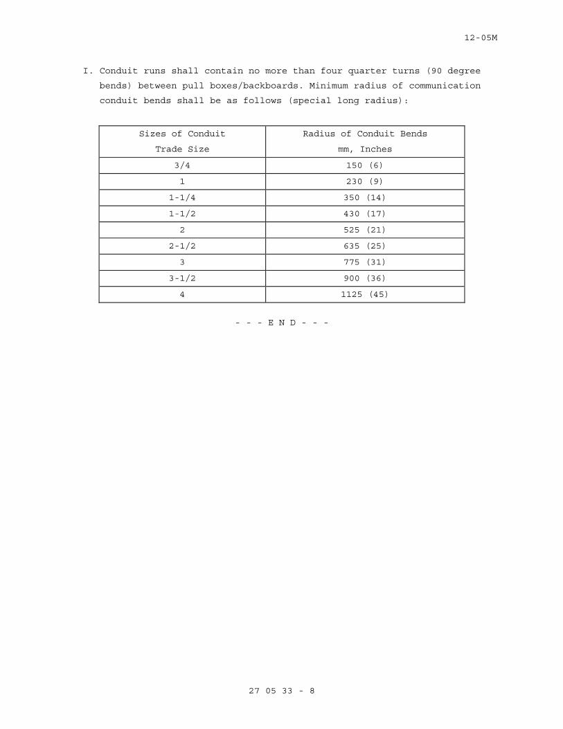
12-05M
27 05 33 - 8
I. Conduit runs shall contain no more than four quarter turns (90 degree
bends) between pull boxes/backboards. Minimum radius of communication
conduit bends shall be as follows (special long radius):
Sizes of Conduit
Trade Size
Radius of Conduit Bends
mm, Inches
3/4 150 (6)
1 230 (9)
1-1/4 350 (14)
1-1/2 430 (17)
2 525 (21)
2-1/2 635 (25)
3 775 (31)
3-1/2 900 (36)
4 1125 (45)
- - - E N D - - -
12-05M
27 10 00 - 1
SECTION 27 10 00 STRUCTURED CABLING
PART 1 - GENERAL
1.1 DESCRIPTION
A. This section specifies the furnishing, installation, and connection of
the structured cabling system to provide a comprehensive
telecommunications infrastructure.
1.2 RELATED WORK
A. Sealing around penetrations to maintain the integrity of time rated
construction: Section 07 84 00, FIRESTOPPING.
B. General electrical requirements that are common to more than one section
in Division 27: Section 27 05 11, REQUIREMENTS FOR COMMUNICATIONS
INSTALLATIONS.
C. Conduits for cables and wiring: Section 27 05 33, RACEWAYS AND BOXES FOR
COMMUNICATIONS SYSTEMS.
D. Requirements for personnel safety and to provide a low impedance path
for possible ground fault currents: Section 27 05 26, GROUNDING AND
BONDING FOR COMMUNICATIONS SYSTEMS.
1.3 SUBMITTALS
A. In accordance with Section 01 33 23, SHOP DRAWINGS, PRODUCT DATA, AND
SAMPLES, furnish the following:
1. Manufacturer's Literature and Data: Showing each cable type and
rating.
2. Certificates: Two weeks prior to final inspection, deliver to the COR
four copies of the certification that the material is in accordance
with the drawings and specifications and has been properly installed.
1.4 APPLICABLE PUBLICATIONS
A. Publications listed below (including amendments, addenda, revisions,
supplements and errata) form a part of this specification to the extent
referenced. Publications are reference in the text by the basic
designation only.
B. American Society of Testing Material (ASTM):
D2301-04................Standard Specification for Vinyl Chloride
Plastic Pressure Sensitive Electrical Insulating
Tape
C. Federal Specifications (Fed. Spec.):
A-A-59544-00............Cable and Wire, Electrical (Power, Fixed
Installation)
D. National Fire Protection Association (NFPA):
12-05M
27 10 00 - 2
70-05...................National Electrical Code (NEC)
E. Underwriters Laboratories, Inc. (UL):
44-02...................Thermoset-Insulated Wires and Cables
83-03...................Thermoplastic-Insulated Wires and Cables
467-01..................Electrical Grounding and Bonding Equipment
486A-01.................Wire Connectors and Soldering Lugs for Use with
Copper Conductors
486C-02.................Splicing Wire Connectors
514B-02.................Fittings for Cable and Conduit
1479-03.................Fire Tests of Through-Penetration Fire Stops
PART 2 - PRODUCTS
2.1 CONTROL WIRING
A. Unless otherwise specified in other sections of these specifications,
control wiring shall be as specified for power wiring, except the
minimum size shall be not less than No. 14 AWG.
B. Control wiring shall be large enough so that the voltage drop under
inrush conditions does not adversely affect operation of the controls.
2.2 COMMUNICATION AND SIGNAL WIRING
A. Shall conform to the recommendations of the manufacturers of the
communication and signal systems; however, not less than what is shown.
B. Wiring shown is for typical systems. Provide wiring as required for the
systems being furnished.
C. Multi-conductor cables shall have the conductors color coded.
2.3 WIRE LUBRICATING COMPOUND
A. Suitable for the wire insulation and conduit it is used with, and shall
not harden or become adhesive.
2.4 FIREPROOFING TAPE
A. The tape shall consist of a flexible, conformable fabric of organic
composition coated one side with flame-retardant elastomer.
B. The tape shall be self-extinguishing and shall not support combustion.
It shall be arc-proof and fireproof.
C. The tape shall not deteriorate when subjected to water, gases, salt
water, sewage, or fungus and be resistant to sunlight and ultraviolet
light.
D. The finished application shall withstand a 200-ampere arc for not less
than 30 seconds.
E. Securing tape: Glass cloth electrical tape not less than 0.18 mm
(7 mils) thick, and 19 mm (3/4 inch) wide.

12-05M
27 10 00 - 3
PART 3 - EXECUTION
3.1 INSTALLATION, GENERAL
A. Install all wiring in raceway systems.
B. Wire Pulling:
1. Provide installation equipment that will prevent the cutting or
abrasion of insulation during pulling of cables.
2. Use ropes made of nonmetallic material for pulling cables.
3. Attach pulling lines for cables by means of either woven basket grips
or pulling eyes attached directly to the conductors, as approved by
the COR.
4. Pull in multiple cables together in a single conduit.
3.2 CONTROL, COMMUNICATION AND SIGNAL WIRING INSTALLATION
A. Unless otherwise specified in other sections, install wiring and connect
to equipment/devices to perform the required functions as shown and
specified.
B. Except where otherwise required, install a separate power supply circuit
for each system so that malfunctions in any system will not affect other
systems.
C. Where separate power supply circuits are not shown, connect the systems
to the nearest panelboards of suitable voltages, which are intended to
supply such systems and have suitable spare circuit breakers or space
for installation.
D. Install a red warning indicator on the handle of the branch circuit
breaker for the power supply circuit for each system to prevent
accidental de-energizing of the systems.
E. System voltages shall be 120 volts or lower where shown on the drawings
or as required by the NEC.
3.3 CONTROL, COMMUNICATION AND SIGNAL SYSTEM IDENTIFICATION
A. Install a permanent wire marker on each wire at each termination.
B. Identifying numbers and letters on the wire markers shall correspond to
those on the wiring diagrams used for installing the systems.
C. Wire markers shall retain their markings after cleaning.
3.4 EXISITNG WIRING
A. Unless specifically indicated on the plans, existing wiring shall not be
reused for the new installation. Only wiring that conforms to the
specifications and applicable codes may be reused. If existing wiring
does not meet these requirements, existing wiring may not be reused and
new wires shall be installed.
- - - E N D - - -
10-06M
27 15 00 - 1
SECTION 27 15 00
TELECOMMUNICATIONS
PART 1 - GENERAL
1.1 DESCRIPTION
A. The project described herein covers a telecommunications cable subsystem serving Wm. S. Middleton Memorial Veterans Hospital in Madison, WI.
Services and materials covered under this specification include
provision, installation, test and documentation of cable, and
termination hardware.
B. The Horizontal Cabling System described by this document is based on the installation of Category 6, 4-Pair Unshielded Twisted Pair (UTP) for
Voice and Data. Cables are to be installed from Standard Information
Outlet to the Telecommunications Rooms.
C. The drawings show the locations and types of telecommunications outlets to be installed, each identified by a unique icon.
D. The contractor is responsible for proposing an integrated design with all cable and termination components working together as a system. Where
performance specifications are noted it is intended that these
parameters reflect Channel performance including cable, termination
hardware and Patchcords.
E. The contractor is responsible for all cabling and terminations in all locations shown on the contract drawings. As well as installation of
accessories, wire wrap, cabling, jacks and faceplates in the owner
provided systems furniture and storage shelving as indicated on the
contract drawings.
PART 2 – PRODUCTS
2.1 SUBMITTALS
A. Prior to the start of work the Contractor shall submit, to the VA, four (4) sets of Manufacturers Data covering all products proposed.
The submittals shall be original catalog sheets or photocopies.
B. Contractor shall submit all written documentation from a bonafide installer training and certification program for all persons doing the
installation. Certifications shall indicate the installers meet
category 6 and current industry standards.
C. Work shall not begin without the approval of the submitted items by the VA. The VA shall review the submittals and mark with approval and
return to the contractor.
10-06M
27 15 00 - 2
2.2 VOICE AND DATA CABLES
A. All Cables (Cat 6 or better) shall be constructed of four (4) individually twisted pairs with 24 AWG insulated copper conductors.
Pairs of all cables will be unshielded and will be identified by a
banded color code in which conductors are marked with a dominant color
and banded with a contrasting color, which will be the dominant color of
its mate. By pair number, the pair colors (Dominant / Band) are:
1. Pair 1: Tip - White/Blue; Ring - Blue (or Blue/White) 2. Pair 2: Tip - White/Orange; Ring - Orange (or Orange/White) 3. Pair 3: Tip - White/Green; Ring - Green (or Green/White) 4. Pair 4: Tip - White/Brown; Ring - Brown (or Brown/White)
B. All Cable shall meet the physical requirements of ANSI/TIA/EIA-568-A Standard for Commercial Building Wiring, Underwriters Laboratory (UL)
listed and complies with Article 800 (Communications Circuits) of the
National Electrical Code.
C. All Cables and Termination hardware shall be technically compliant with and installed in accordance with TIA/EIA-568-A.
D. All Voice and Data cables and all associated Termination Components shall be selected from distributor stock that is independently verified
for performance. The manufacturer shall be Cat 6, Panduit, to match
existing hospital systems.
E. All Cables shall meet a CMR (Riser) rating and shall be suitable for installation in "free-air" in building risers, above non-plenum drop
ceilings, in cable tray or in duct.
F. All Cable jacket colors shall be Yellow and Green; Yellow for voice &
Green for data cables. Any variance from this shall not be done without
written approval from the VA Project Manager.
2.3 TELECOMMUNICATIONS OUTLET
A. The Telecommunications Outlet shall consist of a mounting frame designed for use with a minimum of four (4) modular jacks. Voice and Data jack
assemblies shall snap in to the mounting frame. Any unused jack
positions will be fitted with a removable blank cover. Color of the
frame and snap-in assemblies or covers shall be Ivory.
B. All voice and data jacks shall be selected from distributor stock that is independently verified for performance. The manufacturer shall be The
Panduit Corporation, to match existing hospital systems.
C. Voice and Data Cables shall each be terminated at the outlet in an eight-pin modular Jack.
10-06M
27 15 00 - 3
D. The interface between the jack and the station cable shall be a 110-Style IDC connection. Contractor to provide 110-Style IDC Blocks:
Panduit M/N: GPKBW24.
E. Voice and Data jacks should have an "angled shroud" design, with a downward angle of approximately 45 degrees.
F. All Jacks are to be pinned per T568A wiring configuration with the pairing as follows:
1. Pair 1 - Pins 5&4 2. Pair 2 - Pins 3&6 3. Pair 3 - Pins 1&2 4. Pair 4 - Pins 7&8
G. Jacks are to be identified using a color coded insert which also incorporates an icon indicating the application. Jack positions are to
be identified as follows:
1. All jacks - Yellow "PC" Icon H. This project requires a total of 3 jacks at each location, three yellow
jacks and one blank unless otherwise noted on the project drawings.
Panduit M/N: CJ688TGYL.
2.4 PATCH CORDS
A. Patch cables shall be provided by the contractor. The contractor shall supply the patch cords in the length and color dictated by the VA. If no
length is dictated by the VA the patch cords shall be provided as
follows; Ten(10) feet at the work station and Five (5) at the Patch
Panel in the Telecommunications Room. Ten footers to be Red and Five
footers to be blue.
B. All patch cords shall be selected from distributor stock that has been independently verified for performance. The manufacturer shall be The
Panduit Corporation, to match existing systems.
2.5 CONDUIT SYSTEM
A. All Conduit: ¾” minimum (EMT) B. Innerduct Raceway: 1” corrugated PVC tubing, Flex-Plus Blue ENT by
Carlon or approved equal.
2.6 VOICE AND DATA TERMINATION IN TELECOMMUNICATION ROOM
A. At the Telecommunication Room, each 4-pair UTP Cable shall be terminated on a 19” rack mountable patch panel. The patch panels shall be selected
from distributor stock that is independently verified for performance.
The manufacturer shall be The Panduit Corporation.
B. The interface between the jacks at the patch panel and the data cable shall be a 110-Style IDC connections terminated to the T568A wiring
configuration. Patch Panels shall be designed to maintain the cable
10-06M
27 15 00 - 4
pair twists as closely as possible to the point of mechanical
termination. The installer shall insure that the twists are preserved
to within 1/2" of the termination. Patch Panels: Panduit M/N:
CPPLA48HDWBL.
C. The panels must provide strain relief for the incoming station cables. D. All pair combinations must be considered, with the worst-case
measurement being the basis for compliance.
E. Panels shall be designed and installed in a fashion as to allow future station cabling to be terminated on the panel without disruption to
existing connections.
F. The number of ports the patch panel shall have is to be determined and stated by the VA or its designated representative.
G. The contractor shall furnish and install vertical and horizontal cable management hardware on each rack to neatly and securely route modular
jumper cables. At a minimum, (1) one 3.5” horizontal cable management
panel shall be provided for each increment of forty-eight (48) positions
on the patch panels.
H. Face Plates to be 4 port-angled. Face Plate Color: Off-white or Ivory. Submit samples.
PART 3 - EXECUTION
3.1 INSTALLATION - GENERAL
A. The contractor will be responsible for identifying and reporting to the
VA Project Manager (VAPM) any existing damage to walls, tiles and
furnishings in the work area prior to start of work. All damage to
interior spaces caused by the installation of cable, raceway or other
hardware must be repaired. Repairs must match preexisting color and
finish of walls, floors and ceilings. Any contractor damaged ceiling
tiles are to be replaced to match color, size, style and texture.
3.2 CABLE INSTALLATION - GENERAL
A. Cables shall be routed "free-air" from the Telecommunication Room to the location of the Telecommunications Outlet. Cables shall be installed as
to not rest on the ceiling grid. Cable shall be supported via "J
Hooks" no bridle rings will be allowed. Cables shall not be attached to
existing cabling, plumbing or steam piping, ductwork, or electrical or
communications conduit. Supports shall be spaced 48” to 60” apart.
B. Cable sheaths shall be protected from damage from sharp edges. Where a cable passes over a sharp edge, a bushing or grommet shall be used to
protect the cable.

10-06M
27 15 00 - 5
C. To reduce or eliminate EMI, the following minimum distances shall be adhered to. The contractor shall notify the VAPM if installation
conditions inhibit these guidelines.
1. Five (5) inches from power lines of 2kVa. 2. Thirty (30) inches from high voltage lighting (including
fluorescent).
3. Thirty-nine (39) inches from power lines of 5kVa or greater. 4. Thirty-nine (39) inches from transformers and motors.
D. The maximum station cable drop length shall not exceed 295 feet (90 meters) in order to meet data communications performance
specifications. This length is measured from the termination in the
Telecommunications Room to the Termination at the work area outlet and
must include any slack required for the installation and termination.
The Contractor is responsible for installing station cabling in a
fashion as to avoid unnecessarily long runs. Any area that cannot be
reached within the above constraints should be identified and reported
to the VAPM prior to installation.
E. Where multiple cables join on a common route, they shall be combined into a single bundle, secured with Velcro straps and labeled (1) at the
point at which they enter a space such as the hallway where multiple
cable bundles shall be routed and (2) the point at which the bundle(s)
enter the Telecommunication Closet. Labeling shall identify VA
ownership and list all Telecommunication Spaces that are served by that
cable bundle.
F. In the Telecommunication Room, all cable shall be routed in a fashion as to provide adequate slack to allow for the cable to be rerouted to the
equipment rack location and terminated on a modular panel. The plan
for this routing must be reviewed and approved by the VAPM prior to
construction. The review does not exempt the Contractor from meeting
any of the requirements stated in this document.
G. Align and install cables parallel and/or perpendicular to the building lines.
H. Provide conduit sleeves, as required, channel in wall if necessary, for all wall & floor locations. All cabling shall be run in the walls and
be in conduit, stubbed to above the ceiling.
3.3 OUTLETS AND TERMINATION HARDWARE – GENERAL
A. Telecommunications Outlet and Telecommunication Room termination hardware shall be designed to maintain the cable's pair twists as
closely as possible to the point of mechanical termination. The
10-06M
27 15 00 - 6
installer shall insure that the twists are preserved to within 1/2" of
the termination for all Cables.
B. Termination Hardware (Patch Panels) Positioning and Layout must be reviewed and approved by the VAPM or its agent prior to construction.
The review does not exempt the Contractor from meeting any of the
requirements stated in this document.
C. All Cables, Telecommunications Outlets, Voice Blocks and Data Patch Panels shall be clearly labeled using a Code identifying the location as
unique throughout the Facility. The labeling and administration of it
shall be done as stated in the TIA/EIA-606-A. Administration Standard
for Commercial Telecommunications Infrastructure. The owner shall
determine the class of administration that the contractor will follow.
The labeling scheme shall be approved by the VA prior to implementation.
ALL labeling must mechanically printed in black ink. Hand lettered
designations are not acceptable. When labeling cables, self-laminating
labels are to be wrapped around the cable (e.g. not a "flag").
1. Telecommunications Outlets are to be labeled on the cover of the faceplate and on each cable terminated at that location within 12
(twelve) inches of the end of the jacket.
2. In the Telecommunication Room, all Voice and Data Termination Hardware and cables shall be labeled with the ID corresponding to the
faceplate number to which the component relates. Cables shall be
positioned in sequence of the faceplate I.D. starting with the lowest
number.
3.4 TESTING
A. Contractor is responsible for supplying all equipment and personnel necessary to conduct the acceptance tests. Contractor shall conduct
acceptance testing according to a schedule coordinated with the VA.
Representatives of the VA may be in attendance to witness the test
procedures. The contractor shall offer adequate advance notice to the
VA as to allow for such participation .
B. All horizontal cables must be 100% tested and fault free. If any cable is found to be outside the specification defined herein, that cable and
the associated terminations shall be replaced at the expense of the
contractor. Upon completion, the applicable tests shall be repeated.
C. Horizontal Cable testing shall be as follows: 1. Contractor shall perform all of the measurements required by
TIA/EIA-568-B and/or 586-A channel test. All pair combinations shall
be tested with compliance based upon the worst case pair
combination.
10-06M
27 15 00 - 7
2. To determine Nominal Velocity of Propagation (NVP) values shall be calculated by the contractor by terminating a known length of cable
as required by the tester manufacturer and performing the necessary
test. This NVP will be utilized during the testing of the installed
cable plant. This requirement can be waived if NVP data is
available from the cable or tester manufacturer for the exact cable
type under test.
2. Testing shall be performed using a TIA Level III tester. D. At minimum, the VA may request that a 5% random field re-test be
conducted on the cable system - at no additional cost - to verify
documented findings.
E. In the event results of the tests are not satisfactory, the Contractor shall make adjustments, replacement and changes as are necessary and
shall then repeat the test or tests which disclosed faulty or defective
material, equipment or installation method, and shall make additional
tests as the Engineer deems necessary.
3.5 DOCUMENTATION
A. All pathways and spaces not dictated by the drawings shall be drafted, defined and submitted to the VA, by the contractor, prior to the start
of the project. The Contractor shall not start until the VAPM has
approved the drawings in writing. Any work done by the contractor prior
to approval when approval is required shall be removed at the expense of
the contractor if the approval is not granted.
B. Test reports may be submitted in hardcopy or electronic format. Hand written test reports are not acceptable.
C. All test reports shall include the following: 1. Cable Manufacturer, Cable Model number/name, and NVP. 2. Tester manufacturer, model, serial number, hardware and software
version.
3. Circuit ID number and project name. 4. Autotest specification used. 5. Overall pass/fail indication. 6. Results from all of the tests conducted as required by the TIA/EIA-
568-A
7. Contractors name, name of persons performing test, and date of test. D. The contractor shall visually inspect all cabling and terminations to
insure that they are complete and conform to the wiring pattern defined
herein. The contractor shall provide to the VA a written certification
that this inspection has been made.
10-06M
27 15 00 - 8
3.6 AS-BUILTS
A. Upon completion of cable plant installation and testing, the contractor shall provide a complete set of cable records documentation including:
1. Annotated floor plans showing the location of all Telecommunications Outlets as installed. The path and routing of all cabling homeruns.
Telecommunications Outlets shall be identified by the Outlet I.D. and
a unique symbol. Provide hard copy sets and an electronic version on
AutoCAD software.
2. Termination field(s and equipment rack layouts. ---END---
Related Documents