Section 11 Trackwork 11-1 CIP 1210030 – V1.0 SECTION 11 TRACKWORK 11-1 GENERAL 11-1.01 DESCRIPTION OF WORK The work to be performed under this Section shall include, but not be limited to, the following: A. Track reconstruction, which includes: 1. Removal of existing tracks (rail, ties and ballast), existing vehicular and pedestrian crossings, and silted and contaminated ballast; 2. Removal and salvage of existing impedance bonds and other track materials as directed by the Engineer. 3. Installation of ballasted track including: furnishing and installing filter fabric; ballast, new 8’-3” concrete or 8’-0” timber crossties, new track hardware, and new insulated joints; installing owner furnished new 115 RE rail; installing owner furnished 8’-0” concrete crossties; and installing new or salvaged impedance bonds; 4. Furnishing and installing new vehicular pre-cast grade crossing concrete panels on 10’ timber crossties; 5. Furnishing and installing new pedestrian pre-cast grade crossing concrete panels on 8’- 3” concrete crossties; 6. Furnishing and installing drainage and surface improvements as indicated. B. Rail and Tie Replacement, which includes: 1. Removal of existing 75lb, 90lb and 115lb rail from timber crossties; removal of existing timber crossties, and removal of existing 90lb special trackwork; 2. Removal and salvage of existing impedance bonds and other track materials as directed by the Engineer. 3. Installation of new rail and ties including: furnishing and installing new 8’-0” timber crossties, new track hardware, and new insulated joints; installing owner furnished new 115 RE rail; and installing new or salvaged impedance bonds; C. Perform all work necessary to complete the trackwork installation in accordance with the Plans and as specified in these Special Provisions. All track work shall be accomplished without interrupting LRV and Freight Operations in accordance with the requirements in Section 5-1.07, “Maintaining Rail Traffic Operations”; and Section 5-1.06, “Order of Work,” of these Special Provisions. D. Furnish and install new special trackwork at the following locations: 1. One No. 10 Turnout at Station 163+64, S27, north of Harborside Station. 2. One No. 10 Turnout at Station 327+95, S45, south of 24 th Street Station. 3. One No. 10 Turnout at Station 494+51, S67, between L and Moss Street. 4. One No. 10 Turnout at Station 537+55, south of Palomar Street Station, with derail at Station 540+35.

Welcome message from author
This document is posted to help you gain knowledge. Please leave a comment to let me know what you think about it! Share it to your friends and learn new things together.
Transcript
Section 11 Trackwork
11-1 CIP 1210030 – V1.0
SECTION 11 TRACKWORK
11-1 GENERAL 11-1.01 DESCRIPTION OF WORK The work to be performed under this Section shall include, but not be limited to, the following:
A. Track reconstruction, which includes:
1. Removal of existing tracks (rail, ties and ballast), existing vehicular and pedestrian crossings, and silted and contaminated ballast;
2. Removal and salvage of existing impedance bonds and other track materials as directed by the Engineer.
3. Installation of ballasted track including: furnishing and installing filter fabric; ballast, new 8’-3” concrete or 8’-0” timber crossties, new track hardware, and new insulated joints; installing owner furnished new 115 RE rail; installing owner furnished 8’-0” concrete crossties; and installing new or salvaged impedance bonds;
4. Furnishing and installing new vehicular pre-cast grade crossing concrete panels on 10’ timber crossties;
5. Furnishing and installing new pedestrian pre-cast grade crossing concrete panels on 8’-3” concrete crossties;
6. Furnishing and installing drainage and surface improvements as indicated.
B. Rail and Tie Replacement, which includes:
1. Removal of existing 75lb, 90lb and 115lb rail from timber crossties; removal of existing timber crossties, and removal of existing 90lb special trackwork;
2. Removal and salvage of existing impedance bonds and other track materials as directed by the Engineer.
3. Installation of new rail and ties including: furnishing and installing new 8’-0” timber crossties, new track hardware, and new insulated joints; installing owner furnished new 115 RE rail; and installing new or salvaged impedance bonds;
C. Perform all work necessary to complete the trackwork installation in accordance with the Plans and as specified in these Special Provisions.
All track work shall be accomplished without interrupting LRV and Freight Operations in accordance with the requirements in Section 5-1.07, “Maintaining Rail Traffic Operations”; and Section 5-1.06, “Order of Work,” of these Special Provisions.
D. Furnish and install new special trackwork at the following locations:
1. One No. 10 Turnout at Station 163+64, S27, north of Harborside Station.
2. One No. 10 Turnout at Station 327+95, S45, south of 24th Street Station.
3. One No. 10 Turnout at Station 494+51, S67, between L and Moss Street.
4. One No. 10 Turnout at Station 537+55, south of Palomar Street Station, with derail at Station 540+35.
Section 11 Trackwork
11-2 CIP 1210030 – V1.0
5. One No. 10 Turnout at Station 643+81, south of Palomar Street Station.
6. One No. 10 Turnout at Station 663+99, S85, north of Iris Avenue Station.
11-1.02 CODES AND STANDARDS Applicable codes and standards include, but are not limited to:
A. AREMA Manual for Railway Engineering. (Latest Edition in effect at time of bidding)
B. AREMA Portfolio of Trackwork Plans (Latest Edition in effect at time of bidding)
C. Federal Railroad Administration (FRA):
Mainline trackwork shall meet or exceed the requirements of Federal Railroad Administration (FRA) Class 4 Track. Siding trackwork shall meet or exceed the requirements of FRA Class 3 Track.
D. California Public Utilities Commission (CPUC) General Orders:
1. 26-D Clearances on Railroads and Street Railroads with Reference to Side and Overhead Structures, Parallel Tracks, Crossings of Public Roads, Highways and Streets.
2. 143-B Safety Rules and Regulations Governing Light Rail Transit
3. 118 Construction and Maintenance of Walkways and Vegetation Control
E. ASTM International (ASTM):
1. ASTM C 29 Test Method for Unit Weight and Voids in Aggregate.
2. ASTM D 75 Methods for Securing Test Samples.
3. ASTM C88-99a Soundness of Aggregates by Use of Sodium Sulfate or Magnesium Sulfate
4. ASTM C117-95 Materials Finer than No. 200 Sieve in Mineral Aggregates by Washing
5. ASTM C127 Standard Test Method for Density, Relative Density, and Absorption of Coarse Aggregate
6. ASTM C131-96 Resistance to Degradation of Small-Size Coarse Aggregate by Abrasion and Impact in the Los Angeles Machine
7. ASTM C136 Standard Test Method for Sieve Analysis of Fine and Coarse Aggregates
8. ASTM C142-97 Clay Lumps and Friable Particles in Aggregates
9. ASTM C 535 Test Method for Resistance to Degradation of Large-Size Coarse Aggregate by Abrasion and Impact in the Los Angeles Abrasion Machine
10. ASTM D3786 Standard Test Method for Bursting Strength of Textile Fabrics
11. ASTM D4491-99a Water Permeability of Geotextiles by Permittivity
12. ASTM D4533 Standard Test Method for Trapezoid Tearing Strength of Geotextiles
13. ASTM D4632-91 Grab Breaking Load and Elongation of Geotextiles
Section 11 Trackwork
11-3 CIP 1210030 – V1.0
14. ASTM D4716 Standard Test Method for Determining the (In-plane) Flow Rate per Unit Width and Hydraulic Transmissivity of a Geosynthetic using a Constant Head
15. ASTM D4751 Standard Test Method for Determining Apparent Opening Size of a Geotextile
16. ASTM D4791 Standard Test Method for Flat Particles, Elongated Particles, or Flat and Elongated Particles in Coarse Aggregate
17. ASTM D4833-00 Index Puncture Resistance of Geotextiles, Geomembranes and Related Products
18. ASTM D4886 Standard Test Method for Abrasion Resistance of Geotextiles
19. ASTM E10-01 Standard Test Method for Brinnel Hardness of Metallic Materials
20. ASTM E164-97 Standard Practice for Ultrasonic Examination of Welds
F. Caltrans Transportation Laboratory – California Test Methods (CTM):
1. CTM 202 Sieve Analysis of Fine and Coarse Aggregates
2. SSPC SP-10 Near-White Blast Cleaning
11-1.03 SUBMITTALS A. General:
Submittals shall be made in accordance with Section 5-1.02.2, “Submittals,” of the Special Provisions. Shop drawings shall be prepared in accordance with Section 5-1.02.1, “Working Drawings,” of the Special Provisions.
1. Submit manufacturers’ catalog data and certification of compliance on filter fabric (trackbed).
2. Submit quarry source(s), gradation(s), and quality certification(s) on ballast.
3. Submit manufacturers’ catalog data, cut sheets, and certifications as required by these specifications for all contractor furnished materials for approval by the Engineer.
The contactor shall submit a complete list of required submittals for approval by the Engineer.
B. Trackwork Work Plan:
The Contractor shall submit a comprehensive work plan for all trackwork for the Engineer's approval in accordance with the provisions of Section 8-1.04 “Progress Schedule,” and these Special provisions. The plan shall define the Contractor's work sequence, schedule of working hours, methods and procedures to accomplish the required work and shall:
1. Designate the line and profile rails to be used.
2. Specify working hours taking into consideration single tracking operations and other parameters described in Section 10-1.01 “Sequencing Restrictions and Parameters,” the city of jurisdictions Traffic Engineer’s requirements, environmental considerations, and local business and residential access requirements, and scheduled freight movements.
3. Establish procedures for distributing, handling and storing owner furnished rail.
Section 11 Trackwork
11-4 CIP 1210030 – V1.0
4. Include a detailed cutting plan for owner furnished rail.
5. Include a CWR work plan.
6. Do not cut rail strings except as required to fit rail turnouts, crossings or limits of work.
7. Establish a ballast tamping procedure.
8. Establish welding procedures, qualification test result reporting, and welding crew qualification test result reporting. Welding crew shall be certified by the manufacturer.
9. Establish a method for production welding test result reporting.
10. Establish procedures for unloading, stockpiling, distributing and handling ties.
11. Include a method for reporting temperature records for CWR track anchoring.
12. Provide an installation procedure for all trackwork, and removal of existing trackwork.
13. Provide a method for handling all existing and removed ballast.
14. Provide a submittal for the manufacture and installation of end plates for use on wood ties.
Any changes in the work plan shall be submitted 10 working days prior to the institution of that change.
C. Special Trackwork:
1. Submit the manufacturers’ catalog data, brochures, and shop drawings on the following prior to the start of construction of special trackwork:
a. Turnout and switch point geometry.
b. Switch points including braces, switch point rails, elastic rail clips, bolts, insulated gauge rods, rail bonding, and insulated rail joints.
c. Heel block assemblies and associated hardware.
d. Railbound manganese frogs including special plates, elastic rail clips, bolts and fasteners.
e. Guard rails including blocks, special plates, elastic rail clips and fasteners.
f. Insulated gauge plates including elastic rail clips, bolts and fasteners.
2. Submit the following prior to manufacture of special trackwork:
a. Survey existing track centers prior to developing shop drawings for each special trackwork location and include on the prepared drawings.
b. Product data consisting of a listing of product types, names of suppliers and manufacturers, and model numbers of all proposed materials and hardware.
c. Proposed welding and test procedures for welded components.
d. Specification describing the Contractor’s method for marking and identifying sizes and types of the various components to ensure the proper location during installation.
e. Specification describing the Contractor’s method for explosive depth hardening of turnout and frog components in accordance with AREMA hardness requirements.

Section 11 Trackwork
11-5 CIP 1210030 – V1.0
f. Test results and analysis of stock rails and closure rails in accordance with AREMA specifications.
g. A description of shipping, handling, unloading and storage procedures.
h. Trackwork assembly procedures.
The contractor shall submit five (5) sets of manufacturer’s shop drawings for all of the contractor-furnished special trackwork items. Shop drawing sets shall be legible full size drawings and shall contain all information necessary for the proper installation and adjustment of the trackwork. Shop drawings shall be submitted for the Engineer’s approval at least 30 calendar days prior to the start of fabrication for the depicted special trackwork component.
D. Test Results, Reports and Records:
The Contractor shall submit to the Engineer test results, reports and records as specified in
these Special Provisions. The Contractor shall submit the data for the Engineer's approval 10 calendar days prior to the start of any rail work. The data shall include the following and all other results, reports and records specified in these Special Provisions:
1. Alignment measurements
2. Filter Fabric test results
3. Ballast qualification test results
4. Ballast quality control test results
5. Field welding qualification test results
6. Welding crew qualification test results
7. Field welding records (submitted during welding operations)
8. Quality control test results (submitted as work progresses and as required in these Special Provisions)
E. Shop Drawings:
The Contractor shall submit five (5) sets of manufacturer’s shop drawings.
a. No. 10 Turnout with 19’-6” switch points.
b. Bonded Insulated Rail Joint (Plug)
c. 11’ Switch Point Derail (115LB)
Shop drawings shall be submitted for the Engineer’s approval at least 30 calendar days prior to the start of fabrication for the depicted Special Trackwork component. The contractor must field verify existing track centers prior to submitting shop drawings.
F. Measurement and Payment: No separate measurement will be made for the requirements of this section. Full compensation for complying with the requirements of this section shall be considered as included in the contract prices paid for various items of work involved and no additional compensation will be allowed therefore.
Section 11 Trackwork
11-6 CIP 1210030 – V1.0
11-1.04 QUALITY ASSURANCE/QUALITY CONTROL
A. Manufacturers shall have a minimum of 5 years’ experience in a fixed location of the large-scale manufacture of the material it is to supply. The Contractor shall submit proof of compliance to the Engineer.
B. Manufacturers shall have in place a quality assurance program, adhering to the requirements of
ISO 9001, in accordance with Section 10-1.08, “Quality Assurance,” of these special provisions. This may include, but is not limited to first article inspections, source inspections, and on-site surveys. Such compliance shall promote thoroughly tested material that will render long service life to the user. Prime concern must be focused on the necessary formal assurance requirements to insure that material failure cannot be attributed to actions or lack of actions by the manufacturer. A copy of the manufacturer’s QA procedures shall be submitted to the Engineer for approval.
C. Manufacturers shall show to the satisfaction of the Engineer that it has, or can obtain, the
necessary and proper equipment, tool, facilities and means, and that it has the experience, ability and financial resources to perform the work within the time specified to the quality standards required.
Measurement and Payment: No separate measurement will be made for the requirements of this section. Full compensation for complying with the requirements of this section shall be considered as included in the contract prices paid for various items of work involved and no additional compensation will be allowed therefore. 11-2 MATERIALS 11-2.01 TRACKWORK MATERIALS, OWNER FURNISHED The following trackwork materials will be furnished by SANDAG free of charge and are available to the Contractor in the quantities and at the locations specified herein:
1. 8’-0” concrete crossties (not including pads, clips, and insulators) will be furnished by SANDAG and provided in sufficient quantity to complete the work shown on the plans and described in these Special Provisions. The Contractor shall inventory said crossties and notify the Engineer promptly if the quantity of crossties appears to be insufficient to complete the project. Use of SANDAG-furnished concrete ties will be limited to station area track work as indicated on the plans. 8’-0” concrete crossties furnished by the owner shall not be used in conjunction with new pedestrian pre-cast grade crossing concrete panels. SANDAG-furnished concrete crossties will be stored at the Wright Street yard (2155 Hancock Street, San Diego, CA).
2. Up to 192,000 LF of head hardened 115 RE rail in 1,600’ nominal lengths will be
furnished by the SANDAG. The rail will be located between J St and L St on the inland side of the track. If the contractor needs additional rail besides what has been provided, they are responsible for purchasing and providing the additional rail at the Contractor’s expense. SANDAG intends to have additional rail located at this site, which is not to be used by the Contractor for this project. If the additional rail stored at the site is damaged or otherwise harmed by the actions of the Contractor; the Contractor shall have the cost
Section 11 Trackwork
11-7 CIP 1210030 – V1.0
for remedying the damage deducted from any payments due them by the Engineer. SANDAG intends to have the rail delivered to this location by separate contract, with delivery scheduled to occur in three shipments, one prior to the initial working day specified in the NTP and two within the contract duration. The rail delivery is scheduled to occur on weekends beginning at 1:30 AM on Saturday to 4:30 AM on the following Monday using the westbound Blue Line track for staging the rail train and off loading the rail to the field side. The Contractor shall be responsible for coordinating with the rail procurement contractor regarding the scheduled delivery of the rail and required single track closures, and shall cooperate and allow access for the rail delivery as required.
3. Any track materials salvaged by the Contractor as a part of this contract may be used for
trackwork on the contract if the salvaged materials meet the requirements for the subject work and are approved in writing by the Engineer. All track materials salvaged by the Contractor as a part of this contract which are unused shall become the property of the Contractor and Contractor is responsible for removal and disposal in accordance with Section 7-1.13, “Disposal of Material Outside the Railway or Highway Right of Way,” of the Standard Specifications.
The Contractor will be responsible for loading materials, transporting materials and the unloading of materials from the storage locations specified to the project site. The Contractor shall make scheduling arrangements with MTS to allow timely access to the SANDAG-furnished material located at the Wright Street yard. The Contractor shall contact Fred Byle at (619) 595-4937, to coordinate access to owner furnished material. All SANDAG-furnished material shall remain the property of SANDAG. The Contractor shall not remove material in excess of the quantity needed to perform the work specified on the Plans and specifications. Any excess material not used in the work shall be returned to the stock area as directed by the Engineer. The Contractor shall submit a manifest of SANDAG-furnished materials used to the Engineer for approval. Measurement and Payment No separate measurement will be made for the requirements of this section. Full compensation for loading, transporting and unloading SANDAG-furnished material shall be considered as included in the contract prices paid for the various items of work involved, therefore no additional compensation will be allowed. 11-2.02 TRACKWORK MATERIALS, CONTRACTOR FURNISHED The Contractor shall furnish materials as required to construct trackwork at the locations and to lengths specified herein in accordance with the following:
A. Qualification Of The Manufacturer
1. Manufacturers shall have a minimum of 5 years’ experience in a fixed location of the large-scale manufacture of the material it is to supply. The Contractor shall submit proof of compliance to the Engineer.
2. Manufacturers shall have in place a quality assurance program, adhering to the requirements of ISO 9001, in accordance with Section 10-1.08, “Quality Assurance,” of these special provisions. This may include, but is not limited to first article inspections,
Section 11 Trackwork
11-8 CIP 1210030 – V1.0
source inspections, and on-site surveys. Such compliance shall promote thoroughly tested material that will render long service life to the user. Prime concern must be focused on the necessary formal assurance requirements to insure that material failure cannot be attributed to actions or lack of actions by the manufacturer. A copy of the manufacturer’s QA procedures shall be submitted to the Engineer for approval.
3. Manufacturers shall show to the satisfaction of the Engineer that it has, or can obtain, the necessary and proper equipment, tool, facilities and means, and that it has the experience, ability and financial resources to perform the work within the time specified to the quality standards required.
B. Welding kits: Field Welding Kits for 115 RE rail field welds and 115lb/90lb, 119lb/115lb, and 90lb/75lb compromise field welds shall conform to Section 11-4.09, “Rail Welding,” of these Special Provisions.
C. Filter Fabric: The filter fabric shall conform to Section 11-2.04, “Filter Fabric,” of these Special Provisions.
D. Ballast: Shall conform to Section 11-2.03, “Ballast” of these Special Provisions.
E. Timber Crossties: Standard timber crossties shall be 7”x9”x 8’-0” and shall conform to Section 11-2.05, “Timber Crossties,” of these special provisions.
F. Transition Crossties: 7”x9”x10’ Timber crossties provided for installation with the vehicular pre-cast concrete grade crossing panels and 7”x9”x9’, 7”x9”x10’, and 7”x9”x11’ Timber crossties provided for installation as transition between concrete and timber crossties shall conform to Section 11-2.05, “Timber Crossties,” of these special provisions.
G. Timber Switch Ties: Timber switch ties shall be 7" x 9" undrilled hardwood ties in the number and lengths necessary to complete the crossover installations. The number and lengths shown on the plans are advisory only, and reference should be made to the AREMA Portfolio of Trackwork Plans. The switch ties shall be predrilled in the field before spiking, or during pre-assembly. Switch ties shall conform to Volume I, Chapter 30, Part 3.2, "Timber Switch Ties," of the AREMA Manual and these Special Provisions.
H. Contractor Furnished Concrete Crossties: Concrete crossties shall be 8’3” long and shall conform to Section 11-02.06, “Concrete Crossties,” of these special provisions.
I. Vehicular Pre-cast Concrete Grade Crossing Panels: The vehicular pre-cast concrete panels shall conform to Section 11-2.08, “Vehicular Pre-cast Concrete Grade Crossing Panels,” of these Special Provisions.
J. Pedestrian Pre-cast Concrete Grade Crossing Panels: The pedestrian pre-cast concrete panels shall conform to Section 11-2.09, “Pedestrian Pre-cast Concrete Grade Crossing Panels,” of these Special Provisions.
K. Bonded Insulated Rail Joints: Insulated joints shall be glued D-Bar Type for various rail sections as manufactured by Allegheny Rail Products, Inc., VAE Nortrak, or approved equal. Contractor shall supply insulated rail joints already pre-assembled in rail plugs.
L. Compromise Rail Joints: Joints shall be 36 inches long, six bolt toeless configuration in accordance with the requirements of AREMA “Joint Bars and Assembles,” “Rail Drillings, Bar Punchings, and Track Bolts,” and “Design of Track Bolts and Nuts.” Nuts shall be wrench turn fit. Compromise joint plugs shall be installed.
M. Track Spikes (vehicular grade crossing panels and turnouts): Spikes shall be screw-type spikes in accordance with AREMA specifications, to be used in conjunction with elastic fasteners on
Section 11 Trackwork
11-9 CIP 1210030 – V1.0
timber ties within vehicular grade crossing limits. Spikes shall be 6” long with 15/16 inch diameter.
N. Tie Plates for Timber Ties (vehicular grade crossing panels and turnouts): Shall be designed per AREMA material standards and specifications. Tie plates shall be designed to be used in conjunction with elastic fasteners and screw spikes. Tie pads shall be used with all timber ties.
O. Rail Fastening Assembly for Timber Ties (vehicular grade crossing panels and turnouts): Rail fastening systems for timber ties shall consist of galvanized Pandrol Type E Clips, or approved equal, with Pandrol mating plates for 5 ½” base rail as shown on the drawings. Galvanized Pandrol Type J Clips, or approved equal, shall be installed at insulated joints. Plates shall be manufactured for 115 RE rail and four screw spikes shall be installed on each plate.
P. Tie Pads for Timber Ties (vehicular grade crossing panels and turnouts): Rubber/fiber pads shall be designed per AREMA material standards and specifications and be capable of resisting ozone chemicals and weather shall be placed between the tie and the tie plates. Pads shall be 8” x 1/4” x 1” longer than the plate they support.
Q. Track Spikes for Timber Ties (new track on timber ties, rail replacement): Track spikes shall be new 5/8” track spike with reinforced throat and shall to conform with AREMA Volume 1, Chapter 5, Part 2 for “Soft Steel Track Spikes.”
R. Tie Plates for Timber Ties (new track on timber ties, rail replacement): Tie Plates shall be 13 in., 8-hole new double shoulder tie plates with a 40:1 cant. Tie plates and spikes shall conform to AREMA Manual Volume 1, Chapter 5, Plan No. 7, Punch Pattern A.
S. Tie Plugs: Tie Plugs shall be hardwood tie plugs and conform to AREMA’s “Specifications for Tie Plugs.”
T. Rail Anchors shall be new and be one-piece Channeloc type or approved equivalent, of standard weight. They may be normally applied with a sledge hammer or manufacturer’s application tool, and of a design, size and construction to properly fit the base of rail on which being applied and shall conform to AREMA Volume 1, Chapter 5, Part 7.
U. Rail Fastening Assembly for Concrete Ties: Clips, pads, and insulators for concrete crossties shall conform to Section 11-4.06, “Crosstie Placement,” of these Special Provisions.
V. Turnouts: The turnout unit, including switch points, timber switch ties, stock rails, lead rails, closure rails, complete rail bound manganese steel frogs, guard rails, adjustable filler blocks, tie plates, rail clips, switch plates, frog plates, braced tie plates, insulated gauge rods, insulated joints, switch stand, and other components as needed for a complete installation and fully functional turnout.
W. 11’ Switch Point Derail: Derail shall accommodate US&S M23B switch machine, or approved equal, as detailed in the plans.
All materials shall be stored and handled to minimize rust, corrosion and bending. All rail ends shall be protected from physical damage after fabrication. 11-2.03 BALLAST The Contractor shall furnish and place new ballast in accordance with these Special Provisions and as shown on the Plans. The work shall include the furnishing of ballast material, transporting, and placing new ballast. Tamping shall be as specified herein.
Section 11 Trackwork
11-10 CIP 1210030 – V1.0
A. Materials:
Ballast shall conform to Chapter 1, Part 2, “Ballast,” of the AREMA Manual of Railway Engineering. Ballast shall be crushed quarry rock, composed of hard, dense particles of an angular structure providing sharp corners and cubical fragments. Crushed river rock (gravel), slag ballast or limestone will not be acceptable.
1. Deleterious material in the ballast shall not exceed the following amounts, as determined by the appropriate testing method listed:
Minus 200 Sieve 1.0 percent max. (ASTM C 117)
Clay lumps and Friable Particles 0.5 percent max. (ASTM C 142)
2. Wear of the material shall not exceed the recommended values by AREMA, when tested in accordance with ASTM C 535 and C 131.
3. Loss shall not exceed 5 percent after five cycles when tested in accordance with ASTM C88 for Soundness (Sodium Sulfate).
B. Gradation Requirements:
1. Gradation of ballast shall be determined by testing in accordance with ASTM C 136.
2. Ballast installed and completed in track shall conform to AREMA Size No. 4, with the following gradation requirements:
Percent by Weight Sieve Size, Inches Passing Percentage
2 100 1-1/2 90-100
1 20-55 3/4 0-15 3/8 0-5
Ballast meeting these requirements for grading shall have not less than 95 percent crushed particles with three (3) or more faces and not more than one-half percent of uncrushed particles.
This gradation is referred to as AREMA No. 4, nominal 1-1/2” – 3/4,” for identification only. AREMA No. 5 Ballast gradation shall be used on ballast shoulder intended for the maintenance walkway area as shown on the Drawing.
C. Handling:
Ballast shall be kept clean and free of segregation during handling and placing operations.
D. Inspection:
Ballast is subject to inspection by the Engineer at any time between quarry production and compaction in track. Ballast that does not conform to this Specification shall not be used and Engineer will notify the Contractor to stop further ballast operations until the fault has been corrected and defective material has been disposed of without cost to SANDAG.
E. Testing:
Qualification Testing. Ballast at the Quarry shall be qualified prior to production by certified test results submitted for the Engineer's approval not less than five working days prior to beginning of production of ballast. Additional sampling and testing shall be performed if, in Engineer's
Section 11 Trackwork
11-11 CIP 1210030 – V1.0
opinion, there are significant changes in the quarry operation. The Engineer's written approval is required prior to ballast production.
The quality of the source material to be used for ballast shall be determined prior to its acceptance by the Engineer. A test sample of not less than 150 pounds shall be subjected to the following tests by the Contractor’s certified testing laboratory or by an on-site certified technician approved by the Engineer:
a. Deleterious substances (ASTM C 142). b. Los Angeles abrasion (ASTM C 535). c. The percentage of flat and elongated particles (ASTM D 4791). d. Sodium sulfate soundness (ASTM C 88). e. Weight per cubic yard (ASTM C 29). f. Sieve analysis (ASTM C 136). g. Bulk specific gravity and percentage of absorption (ASTM C 127).
F. Quality Control Testing:
1. The Engineer will sample ballast at the time of deposit on the trackbed to ensure uniformity and conformance with the gradation requirements. Test results will be furnished to the Contractor.
2. The Engineer may take additional samples at the quarry and from the in-place ballast. The Contractor shall assist the Engineer in taking the samples. The ballast source shall not change without written authorization from the Engineer.
G. Placement of Ballast:
Subsequent to the excavation of the existing trackway and evidence that the subgrade is satisfactory as prescribed within these Special Provisions, the Contractor shall place filter fabric as described herein. Subsequently, ballast shall be placed as prescribed in Section 11-4.05, “Ballast Placement and Compaction,” of these Special Provisions.
Measurement and Payment:
Ballast shall be measured for payment by the cubic yard.
The quantity of ballast indicated on the bid schedule is determined from the typical section limits shown on the Plans. No allowances will be made for ballast placed outside authorized limits, nor for losses of ballast material due to loading, transporting, unloading, stockpiling, handling, compaction or tamping operations. The Contractor’s attention is directed to Section 10-5.02, “Earthwork” and Section 10-1.13, “Surveying” of these Special Provisions. No compensation will be made for ballast placed in areas outside the limits shown on the Plans unless written approval or direction is given by the Engineer prior to the work being performed. The contract price paid per cubic yard for “Ballast” shall include full compensation for furnishing all labor, materials, tools, equipment and incidentals, and for doing all the work involved in selecting or developing a quarry source; transporting, handling, stockpiling, and distributing; and for all incidentals necessary to complete the work as shown on the plans and as specified in these special provisions.
11-2.04 FILTER FABRIC
This work shall consist of furnishing and installing filter fabric (geotextile) on the subgrade, beneath the ballast, for the purpose of stabilizing the Roadbed as defined by AREMA. The filter fabric shall be
Section 11 Trackwork
11-12 CIP 1210030 – V1.0
installed as shown on the Plans and in accordance with the manufacturer’s recommendations and these Special Provisions.
A. Materials:
The filter fabric shall conform to the provisions in Chapter 1, Part 10, “Geosynthetics,” of the AREMA Manual and these Special Provisions. Filter fabric weighing 16 ounces per square yard (Extra Heavy) shall be used and shall be non-woven, manufactured from polyester, polypropylene, or polypropylene-nylon material, with the following properties. The following tests shall be qualification tests made on two samples of filter fabric. The Engineer will choose the samples and the proposed test shall be conducted by an independent laboratory approved by the Engineer. Results of the test shall be submitted to the Engineer for approval. All testing shall be at no additional cost to SANDAG. Ballast shall not be placed on filter fabric until the Engineer has given written approval to the test results.
Grab Tensile Strength, ASTM D 4632-91 350 lbs. minimum
Elongation, ASTM D 4632-91 20% minimum
Permittivity, ASTM D 4491-99a 0.20 1/sec.
Puncture Strength, ASTM 4833-00 185 lbs. minimum
B. Handling:
Handling, storage and installation, including overlapping, shall conform to the recommendations of the manufacturer. All sheeting damaged during installation or weakened by exposure to sunlight shall be replaced prior to placement of ballast.
C. Placement:
Filter Fabric shall be placed in accordance with AREMA Chapter 1, Section 10, Part 1.5, “Construction Details and Methods.” Specifically, Filter Fabric shall be placed with an overlap of 2 feet in both the longitudinal and transverse directions.
Measurement and Payment
No separate measurement will be made for Filter Fabric.
Full compensation for furnishing and installing Filter Fabric shall be considered included in the contract prices paid for various related items of work, therefore no separate payment will be allowed.
11-2.05 TIMBER CROSSTIES A. General:
Timber Crossties shall be white or red oak hardwood crossties. Crossties shall be drilled for spiking pattern as applicable and as shown in the plans. All hardwood crossties shall be in compliance with Chapter 30, Part 3, “Solid-Sawn Timber Ties,” of the AREMA manual and No. 16 Standard Grading Rules for West Coast Lumber of the West Coast Lumber Inspection Bureau (WCLB). Acceptability of crossties will be based on overall evaluation of quality of the ties, consistent with guidelines of Chapter 30, “Solid-Sawn Timber Ties,” of the AREMA manual.
Tie machining shall conform to the AREMA manual, Volume 1 Track, Chapter 30 Ties Article 3.1.4 Specifications for Machining Cross Ties, 3.1.4.1 General, 3.1.4.2 Adzing, 3.1.4.4 Trimming, and 3.1.4.5 Branding.
All crossties shall be branded or stamped on one end with the manufacturer's symbol to show its identity. Additionally, the year of the tie treatment shall be permanently marked on the same
Section 11 Trackwork
11-13 CIP 1210030 – V1.0
tie end after the top surface of the ties is established. Crossties shall be sawn top, bottom, and sides, cut square at ends with top and bottom parallel and incised on all four faces. Bark shall be entirely removed.
All timber crossties shall be fitted with End Plates to act as anti-splitting devices. Nail plates shall be manufactured and installed per AREMA Chapter 30. All anti-split end plates shall have rounded corners and solid smooth perimeter. Emboss "MTS" followed by the year on all end plates. Material shall be structural type; Grade "C,” 18 gauge galvanized steel, ASTM A446 standard or better, and 4 to 5 teeth per square inch. Teeth shall be 1/2 inch to 9/16 inch long. Poorly sawn timber ties shall be rejected and will not be subject to adzing.
Incise all four tie faces in the patterns given in the AREMA Manual. Incising is recommended prior to seasoning to hasten seasoning, retard splitting & serious checking and permit deeper preservative penetration of recalcitrant woods. Condition and preservative treat all crossties in conformance with AREMA specifications for preservative treatment by pressure methods. All crossties shall be handled carefully so that the protective sheath of preservative remains intact and to prevent exposing untreated heartwood to insect attack.
All materials shall be inspected for quality, size, fabrication, and preservative treatment at the supplier's plant prior to shipment to the job site by an independent inspection agency selected by and paid for by the Contractor and approved by the Engineer.
Inspection reports for the above, including AREMA Record Treatment and Report of Inspection, shall be submitted to the Engineer. Within 10 calendar days of inspection
Measurement and Payment
No separate measurement will be made for timber crossties or associated track hardware. Full compensation for furnishing and installing Timber Crossties and Timber Switch Ties (as required), and the associated crosstie plates, spikes, clips, and insulators, shall be considered included in the contract unit price paid for “Construct New Track on Timber Ties,” “Construct New Track Vehicular Crossing,” “No. 10 Turnout,” “11’-0” Switch Point Derail,” “Crosstie Replacement (Timber Ties),” and “Crosstie Replacement (Transition Timber Ties),” and no additional payment will be made therefore. 11-2.06 CONTRACTOR FURNISHED CONCRETE CROSSTIES Contractor Furnished Concrete Crossties shall be within the following dimensional limits and be designed to withstand 40 ton axle loads and design speeds of 55 MPH for trolley and 40 MPH for freight rail. The finished tie shall not deviate in any dimension from that shown the in the Contract Drawings for the approved tie design by more than the tolerance associated with that dimension.
1. Length: 8’-3” plus or minus 1/4.”
2. Width of Bottom: 8” minimum, 11” maximum ± 1/8.”
3. Width of Top: 7-1/2“ minimum, 10” maximum ±1/8.”
4. Depth: 6-1/4” minimum at any location and 9 1/2” maximum at rail seat, ± 1/8.”
5. Track Gauge: 4-8-1/2,” ± 1/16.”
Section 11 Trackwork
11-14 CIP 1210030 – V1.0
6. Rail Cant: 1 in 40, ± 5, towards the centerline of the tie.
7. Differential Tilt of Rail Seats: Differential tilt in the direction of the rail of one rail seat to the other shall not exceed 1/16” in a width of 6.”
8. The center line of the tie shall be within 1/2” of the center line of track gauge.
9. Chamfer: 1” nominal plus or minus 1/2.”
10. Embedded items to accommodate galvanized Pandrol e-2055 or approved equal rail clips.
11. Tie Spacing: 24.”
The design, fabrication, testing, and delivery of the Contractor Furnished Concrete Crossties shall comply with the requirements of AREMA Chapter 30, Part 4, Monoblock Ties. The Contractor shall not remove concrete ties from the stock area in excess of the quantity needed to perform the work specified on the Plans and specifications. Any excess concrete ties not used in the work shall be returned to the stock area as directed by the Engineer.
Measurement and Payment
Contractor Furnished Concrete Crossties shall be measured by each.
The contract unit price for each “Contractor Furnished Concrete Crossties” shall include full compensation for furnishing all labor, materials, tools, equipment, and incidentals, and for doing all the work involved in furnishing concrete ties to the job site as shown on the plans, as specified in these special provisions, and as directed by the Engineer. 11-2.07 RUBBER RAIL BOOT
A. The Rail Boot should be the Elastomeric Enclosure-Dual Durometer for 115RE Rail section, manufactured by Iron Horse Engineering Company, L.B. Foster Company, or approved equal.
B. The Rail Boot shall be extended to fit the 115RE rail section, while providing for a grinding relief area on the outside of the rail and a flangeway on the inside of the rail. The Rail Boot shall also be lower than the rail by at least 7 mm, but not more than 10 mm, to allow for rail grinding and to avoid wheel threads rolling over the surface of the concrete encapsulating the rails and boot.
C. The Rail Boot shall be extended from Thermoplastic Elastomer with a Shore D durometer hardness of 50+/-5 and co-extended reinforced areas to resist abrading wear at the two top ends of the boot (the top surfaces exposed to traffic and the surfaces in contact with the concrete) and the top of the boot in contact with permanent or temporary rail/boot holding clips.
Measurement and Payment The installation of the rubber rail boot in the San Ysidro Station shall be measured by the track foot. The contract unit price for track foot of “Rubber Boot – San Ysidro” shall include full compensation for furnishing all labor, materials, tools, equipment, and incidentals, and for doing all the work involved in installing the rail boot at this location, as specified in the Standard Specifications and these special provisions and as directed by the Engineer.
Section 11 Trackwork
11-15 CIP 1210030 – V1.0
11-2.08 VEHICULAR PRE-CAST CONCRETE GRADE CROSSING PANELS Grade crossing panels with attached rubber flangeways shall be Precast Concrete Panels w/ Rubber Flangeways by Omega Industries, Inc. (360.694.3221), or approved equal and shall be installed within the locations defined on the plans, as described within these Special Provisions and per manufacturer’s instructions. A. Materials
1. Each panel shall be manufactured using 6000psi. Minimum compressive strength concrete. Cement shall have no more than 0.6% total alkali content. Maximum water/cement ratio = 0.44 (by weight). Air entrainment = 6% +/-1%.
2. Reinforcing steel shall conform to ASTM A706 specification, grade 60. Panels shall be
manufactured for use with wood crossties.
3. Panel frames to be fabricated with minimum 3 x 3 x 3/8 inch angle conforming to ASTM A36 specification. All exposed surfaces of the angle frames shall be painted with a rust inhibitive coating.
4. Each panel shall meet AASHTO HS20-44 Highway/Bridge loading specification with a
30% impact increment. 5. Concrete surface exposed to traffic to have a light broom finish longitudinally and be
sealed. 6. Each gauge panel shall be 49 ½ to 50 ½-inch width x 96 to 97 ½-inch length and
manufactured to the correct height for 115 RE rail. Ties to be spaced 19-1/2-inches on center, or as recommended by the manufacturer.
7. Each field panel shall be 27-inch width x 96 to 97 ½-inch length and manufactured to the
correct height for size rail specified. Ties to be 10 feet length spaced no more than 19-1/2-inches on center.
8. Crossing panels shall be manufactured to be compatible with all common rail fastening
systems and common rail anchors. 9. Each panel to have two (2) galvanized lifting hooks with a minimum 2-ton capacity
and a safety factor 4. Each lifting hook shall be recessed below top surface of panel adequately to prevent vehicular wheel impact. Locations of lifting hooks shall be shown on shop drawings.
10. Tolerances:
a. Width and height = +/- 1/8-inch b. Length = +/- 1/4-inch c. Square = 3/16-inch (measured along diagonal) d. Bottom flatness = +/- 3/32-inch e. Lag holes = +/- ½-inch in any direction f. Lifting hooks = +/- 1-inch in any direction
Section 11 Trackwork
11-16 CIP 1210030 – V1.0
11. Panels shall have pre-attached rubber flangeway fillers that remain stationary and secure throughout their service life. The rubber flangeway fillers shall have the following dimensional and physical properties:
a. Field side shall be 2 ½” width +/-1/4-inch from ball of rail to concrete panel. b. Gauge flangeway width shall be 2 1/2-inch, conforming to current ADA
requirements. c. Gauge flangeway depth shall be 1 ¾-inch to 2 ¼-inches from top of concrete
panel. d. Flangeway fillers shall have an electrical resistivity of 3.11 x 10⁶ Ω/cm or greater.
12. The field and gauge flangeway fillers shall fit in a manner to insure proper fit between the
rail and the concrete panels. The attached flangeway fillers shall accommodate rail anchors and clips.
13. Track curvature greater than 3° requires custom panels to fit radius. Panels will be
tapered equally at each end. Use of filler plates is not allowed. Manufacturer shall provide shop drawings detailing tie spacing, panel arrangement, and special instructions.
14. Manufacturer shall provide owner and engineer with a six (6) year manufacturer’s limited
warranty. Measurement and Payment No separate measurement will be made for Vehicular Pre-cast Concrete Grade Crossing Panels.
Full compensation for furnishing and installing Vehicular Pre-cast Concrete Grade Crossing Panels shall be considered included in the contract unit price paid for “Construct New Track, Vehicular Crossing,” and no additional payment will be made therefore.
11-2.09 PEDESTRIAN PRE-CAST CONCRETE GRADE CROSSING Grade crossing panels with attached rubber flangeways shall be Precast Concrete Panels w/ Rubber Flangeways by Omega Industries, Inc. (360.694.3221), or approved equal and shall be installed within the locations defined on the plans, as described within these Special Provisions and per manufacturer’s instructions. A. Materials
1. Each panel shall be manufactured using 6000psi. Minimum compressive strength concrete. Cement shall have no more than 0.6% total alkali content. Maximum water/cement ratio = 0.44 (by weight). Air entrainment = 6% +/-1%.
2. Reinforcing steel shall conform to ASTM A706 specification, grade 60. Panels shall be
manufactured for use with 8’-3” concrete crossties.
Section 11 Trackwork
11-17 CIP 1210030 – V1.0
3. Panel frames to be fabricated with minimum 3 x 3 x 3/8 inch angle conforming to ASTM A36 specification. All exposed surfaces of the angle frames shall be painted with a rust inhibitive coating.
4. Each panel shall meet AASHTO HS20-44 Highway/Bridge loading specification with a
30% impact increment. 5. Concrete surface exposed to traffic to have a light broom finish longitudinally and be
sealed. 6. Each gauge panel shall be according to the details in the plans and manufactured to the
correct height for 115 RE rail. Ties to be spaced 24inches on center, or as recommended by the manufacturer.
7. Each field panel shall be according to the details in the plans and manufactured to the
correct height for 115 RE rail. Concrete ties to be 8’-3” feet length spaced no more than 24-inches on center.
8. Crossing panels shall be manufactured to be compatible with all common rail fastening
systems and common rail anchors. 9. Each panel to have two (2) galvanized lifting hooks with a minimum 2-ton capacity
and a safety factor 4. Each lifting hook shall be recessed below top surface of panel adequately to prevent vehicular wheel impact. Locations of lifting hooks shall be shown on shop drawings.
10. Tolerances:
a. Width and height = +/- 1/8-inch b. Length = +/- 1/4-inch c. Square = 3/16-inch (measured along diagonal) d. Bottom flatness = +/- 3/32-inch e. Lag holes = +/- ½-inch in any direction f. Lifting hooks = +/- 1-inch in any direction
11. Panels shall have pre-attached rubber flangeway fillers that remain stationary and
secure throughout their service life. The rubber flangeway fillers shall have the following dimensional and physical properties:
a. Field side shall be 2 ½” width +/-1/4-inch from ball of rail to concrete panel. b. Gauge flangeway width shall be 2 1/2-inch, conforming to current ADA
requirements. c. Gauge flangeway depth shall be 1 ¾-inch to 2 ¼-inches from top of concrete
panel. d. Flangeway fillers shall have an electrical resistivity of 3.11 x 10⁶ Ω/cm or greater.
12. The field and gauge flangeway fillers shall fit in a manner to insure proper fit between the
rail and the concrete panels. The attached flangeway fillers shall accommodate rail anchors and clips.
Section 11 Trackwork
11-18 CIP 1210030 – V1.0
13. Track curvature greater than 3° requires custom panels to fit radius. Panels will be
tapered equally at each end. Use of filler plates is not allowed. Manufacturer shall provide shop drawings detailing tie spacing, panel arrangement, and special instructions.
14. Manufacturer shall provide owner and engineer with a six (6) year manufacturer’s limited
warranty. Measurement and Payment Pedestrian Pre-cast Concrete Grade Crossing shall be measured by each crossing installed, as shown in the plans. The contract unit price for each “10’ Pedestrian Pre-cast Concrete Grade Crossing” and “20’ Pedestrian Pre-cast Concrete Grade Crossing” shall include full compensation for furnishing all labor, materials, tools, equipment, and incidentals, and for doing all the work involved in installing pre-cast concrete grade crossing panels (including all required components), cast in place concrete slabs (between tracks), asphalt ramps, at crossing locations as shown on the Plans, as specified in the Standard Specifications and these Special Provisions, and as directed by the Engineer.
11-2.10 RAIL ANCHORS Rail anchors shall be according to Section 11-2.02, “Trackwork Materials, Contractor Furnished” and shall be installed in accordance with Section 11-7.01-1, “Rail Replacement (115lb to 115lb).” Measurement and Payment
Rail Anchors shall be measured for payment by the each.
The contract price paid per each for “Rail Anchors” shall include full compensation for furnishing all labor, materials, tools, equipment, and incidentals, and for doing all the work involved in furnishing Rail Anchors to the job site as specified in these Special Provisions, and as directed by the Engineer.
11-2.11 TIE PLATES Tie Plates shall be according to Section 11-2.02, “Trackwork Materials, Contractor Furnished” and shall be installed in accordance with Section 11-7.01-1, “Rail Replacement (115lb to 115lb).” Measurement and Payment
Tie Plates shall be measured for payment by the each.
The contract price paid per each for “Tie Plates” shall include full compensation for furnishing all labor, materials, tools, equipment, and incidentals, and for doing all the work involved in furnishing Tie Plates to the job site as specified in these Special Provisions, and as directed by the Engineer.
Section 11 Trackwork
11-19 CIP 1210030 – V1.0
11-3 TRACK AND BALLAST REMOVAL 11-3.01 REMOVE EXISTING TRACK The work in this section shall consist of, in general, the removal and disposal, re-installation, or salvage of the existing trackwork materials including rail, turnouts, crossovers, timber crossties, clean ballast, and contaminated ballast. The work in this section applies to “Construct New Track on Timber Ties,” “Construct New Track on Concrete Ties,” “Construct New Track Vehicular Crossing,” “No. 10 Turnout,” and “11’-0” Switch Point Derail” as shown in the plans and specified in these Special Provisions. The Contractor is directed to Section 10-1.03, “Obstruction and Underground Facilities,” where it is stated that all existing underground facilities within the limits of the Project site are to be protected in-place, unless stated otherwise. The Contractor shall use caution when working near existing switches and be careful not to damage existing switch components. The Contractor shall be replace any damaged facilities. A. General
Existing facilities to be salvaged shall be immediately loaded onto trucks, transported, and removed to their predetermined salvage location. No stockpiling of said materials shall occur on MTS property without the approval of the Engineer. Items to be salvaged to MTS that are damaged during removal shall be repaired or replaced as directed by the Engineer at no additional cost to the owner. Salvaged materials shall be protected from theft and damage until such time the materials are delivered and unloaded to the MTS storage facility designated by the Engineer. The Contractor shall provide 5 days minimum notice prior to delivering and unloading materials to the MTS storage facility. The Contractor shall also provide a complete log of materials delivered. The Contractor is responsible to provide the necessary equipment to safely deliver and unload salvaged materials to the MTS storage facility. All trackwork material removed and not shown on the plans or in the special provisions to be salvaged shall become the property of the Contractor and shall be disposed of in accordance with Section 7-5.01, “Disposal of Material Outside the Railway or Highway Right of Way,” of these Special Provisions. Existing preservative-treated timber crossties that are removed during trackwork demolition and are not to be salvaged shall be disposed of in a safe manner in accordance with the relevant Health and Safety Codes of Practice. Prior to cutting any existing continuous welded rail (CWR) at any point, install rail anchors beyond the ends of rails to be cut for 200 feet to anchor CWR when the rails are cut. Maintain rail bonding at all times or use jumpers to maintain track circuits. Rail bonding and track circuits are to be located in accordance with Section 10-1.03 “Obstructions and Underground Facilities” of these Special Provisions. Track circuits shall be arranged such that signals show red when rails are removed. Switch points on crossovers shall be clamped and protected so that out-of-service track cannot be used.
Section 11 Trackwork
11-20 CIP 1210030 – V1.0
B. Remove Existing Trackwork Material
Existing 90LB, 115LB, and 119LB rail material, timber crossties, tie plates and spikes, joint bars, anchors, and other improvements shown on the plans to be removed shall be removed and disposed of by the Contractor.
All materials removed and approved to be disposed of by the Engineer shall become the property of the Contractor and shall be disposed of in accordance with Section 7-5.01, “Disposal of Material Outside the Railway or Highway Right of Way,” of these Special Provisions, and with all applicable laws and regulations.
C. Remove Existing Crossover or Turnout
All rails, switch ties, tie plates, anchors, joint bars, and turnout components removed from the location shown (Crossover and Turnout locations) and not used by the Contractor shall be documented by log, loaded, transported, unloaded and stockpiled in neat stacks and piles at a site designated by the Engineer. All insulated and standard joints from this material shall be removed from existing rails. All other track bolts, nuts, washers, spikes and other railroad appurtenances, not specifically mentioned herein, shall become the property of the Contractor and will be disposed of in accordance with Section 7-5.01, “Disposal of Material Outside the Railway or Highway Right of Way,” of these Special Provisions, and with all applicable laws and regulations. In some areas of the project, it may be necessary to restore rail traffic over the crossover or turnout location after the crossover or turnout is removed. In these areas, new rail shall be welded in place of the turnout components that are being removed, unless indicated otherwise. If new rail is installed on existing switch ties, the cost of installing the rail shall be included in the cost of removing the crossover or turnout. If new rail is installed on new ties, the cost of installing the new rail will be measured and paid for as “Construct New Track on Timber Ties.”
D. Remove Existing Ballast Existing ballast shall be removed within the track limits shown on the track removal sheets. The method of removal shall not disturb the compaction of the underlying materials except where the profile of the track is to be lowered. Existing ballast to be removed shall be tested in situ for contamination and properly disposed of by the Contractor of in accordance with Section 7-5.01, “Disposal of Material Outside the Railway or Highway Right of Way,” of these Special Provisions, and with all applicable laws and regulations. For ballast identified as contaminated by initial, in situ, testing, additional testing of the contaminated ballast shall be performed prior to disposal as required by the disposal facility, with the following minimum testing anticipated:
1. One test per each identified location of contaminated ballast,
2. Four tests per one hundred cubic yards up to 500 cubic yards,
3. One test per 500 yards up to 5,000 cubic yards
4. Additional tests at the frequency required by the disposal facility. Removal of existing subgrade material below the ballast section shall conform to the requirements of Section 10-5.02B, “Roadway Excavation” of these Special Provisions.
Section 11 Trackwork
11-21 CIP 1210030 – V1.0
Measurement and Payment “Remove Existing Ballasted Track” and “Remove Existing Track, Vehicular Crossing” shall be measured for payment for by the track foot. “Remove Existing Turnout” and “Remove Existing Crossover” shall be measured for payment by each unit satisfactorily removed. “Remove Existing Ballast (Clean)” and “Remove Existing Ballast (Contaminated)” shall be measured for payment by the cubic yard. Refer to Section 10-5.02B, “Roadway Excavation” for excavation beyond the limits of existing ballast which is required to achieve the new track section shown in the plans. The contract price paid per track foot for “Remove Existing Ballasted Track” shall include full compensation for furnishing all labor, materials, tools, equipment, and incidentals, and for doing all the work involved in demolition and removal of existing rail; existing concrete and asphalt pavement shown in track removal sheets, insulated joints, crossties, fastening systems, and other track hardware; maintaining rail bonding and track circuits; and loading, transporting and disposing of all removed materials. The contract price paid per track foot for “Remove Existing Track, Vehicular Crossing” shall include full compensation for furnishing all labor, materials, tools, equipment, and incidentals, and for doing all the work involved in demolition and removal of the concrete and rubber panels, existing rail, existing concrete and asphalt pavement shown in track removal sheets, insulated joints, crossties, fastening systems, and other track hardware; maintaining rail bonding and track circuits; and loading, transporting and disposing of all removed materials. The contract unit price paid for “Remove Existing Turnout” and “Remove Existing Crossover” shall include full compensation for furnishing all labor, materials, tools, equipment, and incidentals, and for doing all the work involved in removing existing turnouts and crossovers as part of the work, complete in place, including removing and salvaging existing rail (including all components of existing crossovers and turnouts); installing new rail on existing ties (if necessary to maintain rail traffic); loading, transporting, unloading, and stockpiling materials; removing insulated joints; removing spikes, crosstie plates, and plugging spike holes in all salvaged crossties; as shown on the Plans, as specified in the Standard Specifications and these Special Provisions, and as directed by the Engineer. Full compensation for installing rail anchors, maintaining rail bonding and track circuits, and clamping and protecting turnouts and crossovers shall be considered as included in the contract prices paid for various items of work involved and no additional compensation will be allowed therefore. The contract price paid per cubic yard for “Remove Existing Ballast (Clean)” and “Remove Existing Ballast (Contaminated)” shall include full compensation for furnishing all labor, materials, tools, equipment, and incidentals, and for doing all the work involved in excavation, removal and disposal of existing ballast, including all required testing and reporting. The contract unit price for “Remove Existing Ballast (Clean)” and “Remove Existing Ballast (Contaminated)” will not be subject to adjustment under the provisions of Section 4-1.03 “Changes.” 11-4 TRACK CONSTRUCTION
The work in this section shall consist, in general, of preparing subgrade, installing filter fabric, installing timber or concrete crossties, placing ballast, installing 115 RE rails, installing salvaged 90lb rail on sidings, installing bonded insulated rail plugs conforming to the 115 RE rail section, making rail welds
Section 11 Trackwork
11-22 CIP 1210030 – V1.0
and bolted connections, realigning existing track, lining and surfacing track, and compacting and regulating ballast, all as specified hereafter. The work in this section shall apply to “Construct New Track on Timber Ties,” “Construct New Track on Concrete Ties,” “Construct New Track on Timber Ties (Siding),” and “Construct New Track Vehicular Crossing” as shown in the plans and specified in these Special Provisions. The work in this section shall apply to other work in Section 11 as indicated by reference.
11-4.01 GENERAL REQUIREMENTS The Contractor shall maintain rail bonding at all times to preserve negative return track circuits. The bonds shall conform to the detail for Typical Joint Bond – 250 MCM, SANDAG Standard Plan DWG S-14, “Signaling, Typical Impedance Bond Layout, and Bonding Details.”
The Contractor shall be responsible for disconnecting and reconnecting all track joint bonds and cables within the proposed area of work as needed to install the new improvements. If existing track joint bonds and cables are disturbed, damaged, or destroyed as a result of the Contractor’s operations, they shall be repaired or replaced by the Contractor.
After repair or replacement of track joint bonds and cables is complete, the Contractor shall demonstrate to the Engineer that the repaired or replaced facilities operate properly. 11-4.02 TRACK ALIGNMENT AND GEOMETRY A. General: Track shall be lined to the alignment and top of rail profile indicated on the Plans or
such revised profile grade established by the Engineer, within the tolerances specified.
B. Profile Rail: Top of low (inside) rail on all curves shall be used as grade control. Superelevation shall be obtained only by raising the outer rail in relation to the inner rail. Full superelevation shall be attained within the length of the spiral. Superelevation tags shall be placed on the ties on the gauge side of the high rail. Tags shall be placed with the numbers parallel to the track centerline to read from the track centerline in ¼ inch increments. The tag that indicates full elevation shall be placed perpendicular to the track centerline to read from the low superelevation direction.
C. Line Rail: High (outside) rail on all curves shall be used as line rail.
11-4.03 TOLERANCES Deviations from indicated gauge, cross level, horizontal line, profile grade, and tie spacing shall conform to the following requirements and A, B, and C shall not vary more than 1/8 inch in 31 feet:
A. Gauge: Track gauge shall be 4' 8-1/2,” ± 1/8 inch.
B. Cross Level: Cross level, taken at top of rail, shall be ± 1/8 inch from level on tangent or design superelevation on curve.
C. Deviation from Horizontal Alignment:
1. ± 1/8 inch in 31 feet
2. ± 1/2 inch from the planned alignment
3. + 1/4 inch and minus 0 inches from the planned alignment adjacent to LRT platforms
D. Deviation from Horizontal Circular Curves:
Section 11 Trackwork
11-23 CIP 1210030 – V1.0
1. Adjacent midordinates of 62-foot chords, with half-chord overlaps, shall not vary more than ± 1/8 inch.
2. Average midordinate shall not vary by more than ± 1/4 inch from theoretical midordinate.
E. Deviation from Horizontal Spiral Curves: Midordinate of 62-foot chords, with half-chord overlaps, shall not vary by more than ± 1/8 inch from straight line rate of change.
F. Deviation from Top of Rail Profile Grade: Deviation from top of rail profile grade shall not exceed ± 1/8 inch in 31 feet, and ± 1/2 inch from the vertical alignment shown on the Plans.
G. Crosstie Spacing: Distance between centerline of adjacent crossties shall not vary more than ± one inch from the indicated spacing. Timber ties shall include 22 ties per 39 feet. Concrete ties shall include 20 ties per 40 feet.
11-4.04 TOOLS AND EQUIPMENT
A. On-track equipment shall conform to Chapter 27, Part 2, "Specifications for On-Track Roadway Machines" of the AREMA Manual.
B. Wheel profile shall conform to AAR G-4, 1963, as shown in Chapter 27, Part 2, "Axle Wheel and Hub Specifications for Work Equipment" of the AREMA Manual.
C. Tools used in track construction shall conform to AREMA "Specifications and Plans for Track Tools,” or approved equal. All tools shall be calibrated as appropriate for the use.
D. Equipment shall be maintained to the manufacturer's standards and shall be subject to inspection by the Engineer or MTS.
11-4.05 BALLAST PLACEMENT AND COMPACTION
A. Placement of Ballast:
1. After removal of the existing ballast and grading as required, the Contractor shall ensure that the existing subgrade is compacted to 95% relative compaction. The Contractor shall submit a detailed plan for the compaction process to the Engineer for approval. Ballast shall be placed on filter fabric as specified in Section 11-2.03 of these Special Provisions.
2. Ballast spreading and compacting shall conform to Section 25-1.04, "Spreading,” and Section 25-1.05, "Compacting,” of the Caltrans Standard Specifications. Vibratory squeeze-type tampers and ballast regulator shall be used for ballast compaction. Ballast shall be tamped tightly under and around the crosstie from a point 18 inches inside each rail on both sides of the crosstie to beyond the ends of the crosstie. Ballast around the center of the crosstie between the above limits shall not be tamped.
3. An initial layer of ballast shall be uniformly distributed over the filter fabric and compacted before crosstie distribution, except that ballast shall not be distributed on the roadbed until the subgrade has been accepted by the Engineer. The initial layer of ballast shall be limited to a total compacted depth that will establish the track surface at least four inches below final.
4. Each lift of ballast within the initial layer shall be uniformly spread and compacted with not less than four passes of a vibratory compactor with the following characteristics:
Gross weight: 5000 pounds minimum
Section 11 Trackwork
11-24 CIP 1210030 – V1.0
Drum width: 58 inches minimum
Drum diameter: 42 inches minimum
Each compacted lift within the initial layer shall not exceed a depth of four inches.
The vibratory compactor shall have a weight of not less than 5,000 pounds and shall be capable of applying a dynamic load of not less than 18,000 pounds at a frequency between 1100 to 2000 vibrations per minute. The compacting equipment selected by the Contractor shall be subject to inspection and acceptance by the Engineer.
B. Tamping Procedure:
A detailed ballast tamping procedure covering tamping equipment and method shall be prepared and submitted to the Engineer before start of ballast placement. The procedure shall include a complete description of equipment to be used and variables that can be adjusted, such as the number of insertions of tamping tools per crosstie and the depth of penetration.
C. Rejected Procedures: If tamping does not produce ballast meeting the criteria stated herein, tamping variables shall be adjusted and the procedures repeated until all criteria is met.
Measurement and Payment
Ballast supply shall be measured and paid for per Section 11-2.03, “Ballast” of these Special Provisions. Full compensation for preparation and compaction of subgrade, ballast placement and compaction, including placement, compaction, tamping, and removal of rejected ballast shall be considered as included in the contract price paid per track foot for “Construct New Track on Concrete Ties,” “Construct New Track on Timber Ties,” “Construct New Track on Timber Ties (Siding),” and “Construct New Track, Vehicular Crossing,” therefore no separate payment will be made. 11-4.06 CROSSTIE PLACEMENT A. General
Attention is directed to Section 11-2.05, “Timber Crossties,” Section 11-2.01, “Trackwork Materials, Owner Furnished,” and Section 11-2.06, “Contractor Furnished Concrete Crossties,” of the Special Provisions.
B. Installing Timber Crossties
Prior to installation, Contractor shall perform a final visual inspection of the ties to ensure all new timber crossties to be installed are bored, branded, incised, and without defects. If any new ties are damaged or determined to be defective, Contractor shall replace ties at no additional cost. Contractor shall distribute and place ties in their final locations and shall install ties perpendicular to the track alignment based on the required tie spacing as indicated in the plans and these Special Provisions unless otherwise approved by the Engineer. Ties shall be placed within plus or minus ½ inch of the required spacing. Any discrepancies in tie spacing shall not be additive.
Section 11 Trackwork
11-25 CIP 1210030 – V1.0
Ties shall be placed with the heart wood down and ensure the bottom of each tie is fully supported on the initial ballast layer. Timber crossties placed within grade crossings and any other areas designated by the Engineer shall be of hardwood. Timber ties may be reused at the discretion of the Engineer. All ties to be reused shall be plugged.
C. Installing Concrete Crossties
Prior to the commencement of the crosstie installation, Contractor shall perform a final visual inspection of each tie to ensure all ties and their fastener assemblies are free of defects and equipped with rail fastening assembly. If any Contractor Furnished Concrete Ties are damaged or determined to be defective, Contractor shall replace ties at no additional cost. If any Owner furnished concrete ties are damaged or determined to be defective, Contractor shall obtain replacement ties from the Wright Street yard unless otherwise approved by the Engineer. Care shall be taken to ensure that all crossties are uniformly supported on the roadbed and that no center-binding conditions develop prior to ballasting and tamping. A minimum layer of 3 inches of ballast shall be placed on top of the filter fabric, leveled and compacted before placement of crossties. Crossties shall be installed at right angles to the centerline of track at the designed spacing prior to rail installation.
D. Tie Plates (Timber Crossties)
Tie plates shall be positioned so the batter of the plate will cant the rail to the gauge side and shall be centered on the tie and so applied as to obtain proper bearing of rail. Care should be taken so the outside (field side) shoulders of all tie plates have full bearing against base of rail. Tie plates shall be used as shown on the plans and approved shop drawings. Tie plates for timber crossties at vehicular grade crossings shall be attached to the crossties with screw spikes installed as indicated. Spikes shall be so placed that there will not be less than 2 inches from the center of spike to the edge of the crosstie. Installation of screw spikes and specified resilient fasteners shall be in accordance with manufacturer’s recommendations. Tie plates for timber crossties at new track on timber ties shall be attached to the crossties with cut spikes installed as indicated in the plans. Spikes shall be so placed that there will not be less than 2 inches from the center of spike to the edge of the crosstie.
E. Tie Pads (Timber Crossties, Vehicular Grade Crossing Panels only)
See Section 11-2.02.P herein F. Placement of Rail and Fastenings on Concrete Crossties
1. Crosstie Pads: Rail seats shall be clean and crossties properly positioned prior to placement of pads. Pads shall be accurately positioned and centered on the rail seat. Pads shall be compatible with the rail fastening system with a shape which provides positive means of preventing movement of the pad parallel to the rail. Use elastomer pads with a minimum thickness of 6.5mm or maximum thickness of 10.5 mm. The Rail seat pads shall meet the following specifications:
Hardness: 70-95 durometers, ASTM D2240
Section 11 Trackwork
11-26 CIP 1210030 – V1.0
Tensile strength: 10.3 MPA, ASTM D412 Ultimate Elongation: 250 percent, minimum, ASTM D412 High Temperature Compression Set: not to exceed 40 percent, ASTM D395 Volume resistivity: 1x10¹² ohms-cm.
2. Rail: Rail shall not be dropped into place. Use rollers to facilitate unloading and reduce
the risk of dislocating crossties and crosstie pads. Rail shall not be brought into contact with the crosstie ends during installation. Care shall be taken to prevent damage to pads and insulators by rail heaters.
3. Fastenings: Fastenings, to include clips and insulators, shall be as shown on contract
drawings. The rail clips shall be galvanized Pandrol Type “e” 2055 or approved equal. The insulators shall be glass reinforced nylon Pandrol Type INS-4263 or approved equal.
G. Placement of Rail and Fastenings on Timber Crossties (new track)
1. Rail: Rail shall not be dropped into place. Use rollers to facilitate unloading and reduce the risk of dislocating crossties. Rail shall not be brought into contact with the crosstie ends during installation.
2. Spiking: Spiking for standard track spike fastening systems shall be performed as
follows: a. Spiking pattern shall conform to the plans.
b. Spikes shall be started vertically, square to the base of rail and driven straight. Shank of rail-holding spikes shall have full bearing against base of rail.
c. Care shall be taken not to strike rail or fastenings when driving spikes. Bent spikes shall be removed and replaced with a new spike as approved by the Engineer.
d. Spikes shall not be over-driven.
3. Rail Anchors: In applying rail anchors, they shall be set with full bearing against the side of the tie. Anchors shall not be over-driven. Fractured or spread rail anchors will be rejected. Rail anchors shall be applied prior to operation of trains. Anchors shall be removed and re-applied at the time CWR is de-stressed. Rail anchors shall be applied in accordance with manufacturer’s recommendations.
Measurement and Payment No separate measurement will be made for installing crossties and associated track hardware. Full compensation for installing timber crossties at vehicular crossings, and furnishing and installing the associated crosstie plates, spikes, clips, pads, and insulators (as required), shall be considered as included in the contract price paid per track foot for “Construct New Track, Vehicular Crossing,” therefore no separate payment will be made.
Full compensation for placing and aligning Contractor furnished and Owner furnished concrete crossties and supplying and installing crosstie clips, pads, insulators and fastenings on newly placed
Section 11 Trackwork
11-27 CIP 1210030 – V1.0
ties, shall be considered as included in the contract price paid per track foot for “Construct New Track on Concrete Ties,” therefore no separate payment will be made. Full compensation for placing and aligning timber crossties and supplying and installing crosstie plates, spikes on newly placed ties, shall be considered as included in the contract price paid per track foot for “Construct New Track on Timber Ties” and “Construct New Track on Timber Ties (Siding),” therefore no separate payment will be made. 11-4.07 BONDED INSULATED RAIL JOINTS A. General
Work consists of installing bonded and insulated rail joints along the mainline tracks and sidings, as shown on the plans and as described herein. Each crew and its foreman shall be pre-qualified before installing each type of glued joint by the manufacturer.
B. Bonded Insulated Rail Plugs
All insulated joint plug rails shall be shop fabricated from manufacturer’s furnished high strength rails. Plug rail bonded insulated joint materials shall be as per specified herein. Plug rails length: 18’ - 23’ rail plugs for tangent track and curve track up to 5730’ radius. 39’ rail plugs for track curvature more than 5730’ radius. Materials and shop fabrication shall be in accordance to AREMA 2011 (or issue in effect at the time of bidding), Chapter 4, Part 3 Joining of Rail, Section 3.1-3.13. The Contractor shall install factory assembled insulated joint plugs that have been certified by the manufacturer. Two insulated joints, on opposite rails, shall be installed at each callout and stagger shown on the respective Plan, unless otherwise indicated. Plugs shall be welded into track according to Section 11-4.09, “Rail Welding,” of these Special Provisions.
C. Installation of Insulated Joints
Insulated joints shall be installed at locations shown on the Contract drawings and in conformance with the manufacturer's recommended procedures. Two insulated joints, on opposite rails, shall be installed at each callout on the respective Plan, unless otherwise indicated. Contractor shall install bonded insulated rail plugs at all locations unless indicated otherwise. The center of the joint shall be approximately centered between rail support ties.
The Engineer shall be notified no less than one working day in advance of installation of all insulated joints.
Insulated Rail Joint Electrical Test
Section 11 Trackwork
11-28 CIP 1210030 – V1.0
1. All insulated joints shall be tested after installation into track.
2. Electrical Test
The insulated joint assembly shall be tested in conformance with Section 15-14.02.F of these Special Provisions.
3. The Contractor shall submit test procedures and equipment identification for the
Engineer's review at least 30 Days prior to beginning Work. The electrical test shall be performed by a certified electrician employed by the Contractor and approved by the Engineer.
4. Results of the electrical test shall be submitted to the Engineer for approval.
5. Any insulated joint that fails the electrical test in track shall be removed, replaced and retested at Contractor's expense. Replacement procedure shall be approved by the Engineer.
Measurement and Payment Bonded insulated rail joints (plugs) shall be measured by each joint satisfactorily installed.
The contract unit price paid for “Bonded Insulated Rail Joints” shall include full compensation for furnishing all labor, materials, tools, equipment, and incidentals, and for doing all the work involved in constructing Bonded Insulated Rail Joints, complete in place, including any required demolition and replacement of surface improvements, as shown on the Plans, as specified in these Special Provisions. 11-4.08 RAIL LAYING
115 RE Continuously Welded Rail (CWR) shall be loaded, handled, transported, unloaded, and installed in accordance with the requirements of "Handling and Transporting of Continuous Welded Rail" in Chapter 5, Part 5.2.3 of AREMA Manual of Railway Engineering, except as modified herein.
The Contractor is cautioned that rail lengths vary. Careful investigation and verification of field conditions and locations of existing rail joints where CWR is to be connected are to be noted to determine the actual lengths of rail strings required. Field welds within the limits of rail shown are not permissible unless approved in writing by the Engineer. In no case shall new rail be furnished in lengths of less than 80 feet unless approved by the Engineer.
The Contractor shall use existing salvaged 90lb rail, approved by the Engineer, to join new 115lb rail to existing 75lb rail within sidings as shown in the plans.
A. Temperature Adjustment: Track shall be fully spiked (fastened), ballasted sufficiently to prevent tie movement, and lined and surfaced prior to final rail adjustment and anchoring. CWR shall be anchored after rail is adjusted to zero thermal stress at a rail temperature of 105 degrees, +10 degrees, -5 degrees F. The Contractor may heat, cool, or stretch the rail to meet this requirement.
1. Rail Temperature. Rail temperature shall be determined during rail anchoring by means of a standard AREMA rail thermometer. The Contractor shall furnish sufficient rail thermometers for the Engineer’s use during field welding and de-stressing operations. Thermometers will be returned to the Contractor after completion of the work. Temperature of rail shall be determined by placing the rail thermometer on the shaded
Section 11 Trackwork
11-29 CIP 1210030 – V1.0
side of the rail base next to the web, and leave until no change in its reading is detected. In no case shall the thermometer be removed in less than five minutes.
2. Temperature Records. Information to be recorded shall be:
a. Date and time for each string installed. b. Location by station, left or right rail, and string length. c. Rail temperature, air temperature, and weather conditions. d. Rail gap to nearest 1/16 inch.
B. Rail Cuts and End Preparation: Rails shall be cold-sawn, square across the rail, with maximum 1/32 inch deviation from square. All burrs shall be removed and ends made smooth. Bevelling of rail ends is required at all bolted joints, conforming to Plan No. 1005 in the AREMA Portfolio of Trackwork Plans.
After cutting and bevelling, rail ends in standard rail shall be end hardened by a hardening process proposed by the Contractor, which will provide a uniform hardness pattern across the top surface of the rail head for 2 inches from the end. The Brinell hardness number, when tested in conformance with ASTM E10, shall be between 370 and 401, starting 1/4 inch from the end, and shall decrease uniformly to the hardness of the untreated rail 2 inches from the end.
The Contractor shall submit a test of the hardening process, out of track, with Brinell hardness tested by an independent testing laboratory engaged by the Contractor and approved by the Engineer. Tests shall be made on the rail centerline and 3/4 inch on each side of the centerline, starting at 1/4 inch from the end and at three other cross sections, 1 inch, 2 inches, 3 inches, and 4 inches from the end. If the tests do not indicate acceptable results, the procedure shall be modified and re-tests made until acceptable test results are achieved.
After final alignment of each section of track to the specified tolerances, but prior to final acceptance, the Contractor shall grind top and gauge side of running rails using a high-speed rail mounted fine granite grinder, such as Loram “L” series or approved equal, set to grind a minimum of 0.025 mm and a maximum of 0.051 mm with each pass. The Contractor shall grind running rails, switch rails and frogs to original manufacturer’s profile insuring to remove all mill scale and pits. The equipment and method of operation used by the Contractor shall be approved by the Engineer prior to initiation of rail grinding. At the direction of the Engineer, grinding may be delayed until all of the rail at all locations has been laid.
Measurement and Payment: No separate measurement will be made for the requirements of this section. Full compensation for preparing and laying new rail and rail grinding shall be considered as included in the contract prices paid for “Rail Replacement (115lb to 115lb),” “Rail Replacement (90lb to 115lb),” “Construct New Track on Concrete Ties,” “Construct New Track on Timber Ties,” “Construct New Track on Timber Ties (Siding),” and “Construct New Track, Vehicular Crossing,” therefore no separate payment will be allowed.
11-4.09 RAIL WELDING All field welds shall use exothermic methods conforming to the requirements of Chapter 4, Part 2.5, “Thermite Welding – Rail Joints” of the AREMA Manual, except as modified herein.
All factory (shop) welding shall be in accordance with Chapter 4, Part 2.2 “Specifications for Fabrication of Continuous Welded Rail,” of the AREMA Manual, and these Special Provisions.
Section 11 Trackwork
11-30 CIP 1210030 – V1.0
All welding shall be performed under the direct supervision of a welding foreman or supervisor with a minimum of five years documented experience supervising field welding. In addition, a manufacturer's representative experienced in thermite field welding shall be present at the job site on an as-needed basis and shall witness the making of thermite welds for acceptance.
Prior to production welding, each crew, including foreman or supervisor of that crew, shall prepare a qualification weld in 115RE rail, out of track, at the expense of the Contractor. The weld shall be prepared in accordance with the approved procedure Specification and will be witnessed by the Engineer. Testing: Testing agency shall visually inspect the crew qualification welds and perform ultrasonic testing and Brinell hardness testing on each. Test Record: The test record shall contain the names of the crew members, including foreman or supervisor of that crew, who performed the qualification weld and briefly describe their specific duties. The test records shall also show results of visual inspection, ultrasonic testing and rail hardness test. All performance qualification records shall be submitted to the Engineer at least 14 calendar days prior to production welding. Production welding shall not commence until qualification test welding records have received written approval by the Engineer. Requalification: The Engineer reserves the right to require the re-qualifications, at the Contractor's expense, of any crew of welders whose work fails to meet the specified requirements.
A. Weather: Field welding shall not be done during inclement weather. Inclement weather shall
include, but not be limited to, rain and fog.
B. Location: Field welds shall be in accordance with the following restrictions:
1. Compromise welds in opposite rails shall be staggered at least 10 feet except where closer spacing is required by field conditions and is approved by the Engineer.
2. Field welds shall not be located within 19 feet of a bolted rail joint.
3. Field welds shall not be positioned within 3 inches from the edge of a tie plate or concrete tie. All joints, whether bolted or welded, shall be suspended between ties.
4. Field welds shall not be located within 8 feet of an existing field, shop, or factory weld.
5. Field welds shall not be located within the limits of a vehicular or pedestrian crossing.
C. Alignment: The ends of the rails to be welded shall be properly gapped and aligned to produce a weld that will conform to the following alignment tolerances. Cutting back and/or straightening of bent rail ends will be considered incidental to this work. The rail gap alignment shall be held by a hydraulic rail puller/expander and alignment jig without change during the complete field welding cycle. If the rail gap is larger than manufacturer's recommended gap after the rails have been adjusted for zero thermal stress, then sufficient rail shall be removed from one or both rails to permit insertion of a rail not less than 19 feet long, which shall provide the recommended gaps at each end of the field welding. At a location where the rail gap is smaller than the manufacturers recommended gap, the recommended gap shall be obtained by sawing a piece from one rail.
1. Alignment of rail shall be done on the head of the rail:
a. Vertical alignment shall provide for a flat running surface. Any difference of height of the rails shall be in the base.

Section 11 Trackwork
11-31 CIP 1210030 – V1.0
b. Horizontal alignment shall be done in such a manner that any differences in the width of heads of rail shall occur on the field side.
2. Horizontal offsets at joints shall not exceed 0.040 inch in the head and 0.125 inch in the base.
3. Surface Misalignment Tolerance:
a. Combined Vertical Offset and Crown Camber shall not exceed 0.040 inch per foot at ambient temperature.
b. No Dip Camber shall be allowed.
4. Gauge Misalignment Tolerance: Combined Horizontal Offset and Horizontal Kink shall not exceed 0.040 inch per foot at ambient temperature.
D. De-Stressing and Final Anchoring of Field Welded Rail:
1. After each track has been surfaced and lined, and the ballast has been compacted and dressed, the rail fasteners shall be loosened and the rails adjusted to an effective zero thermal stress at a designated rail temperature of 105 degrees F (plus10 degrees/minus 5 degrees F). De-Stressing limits shall extend 200 feet into existing track on each side of the new trackwork limits or to a restriction that prevents rail movement, whichever is greater.
2. The Contractor may heat, cool, and stretch the rails to meet this requirement using rail heaters, cooling water, and hydraulic rail expanders. If rail stretching is to be utilized, it shall be used in conjunction with heaters and during the anticipated warmest period of the day.
3. Rails shall be fully anchored to the ties and all open joints welded while the rails are maintained in the required temperature-stretched condition specified above. Prior to anchoring and welding, rails will be vibrated. Final closure shall be by a field weld with the rail fully fastened (expect immediately adjacent to the field weld as necessary to perform the weld) near or at final elevation and alignment. If post closure rail realignment is required, the Contractor shall provide sufficient longitudinal restraint either side of the location of realignment to assure the rail stress state is not changed by the realignment Work.
4. Rail temperature shall be determined during rail anchoring by means of a standard AREMA rail thermometer. The Contractor shall furnish the Engineer with two rail thermometers at the Contractor’s expense. Temperature of rail shall be determined by placing the rail thermometer on the shaded side of the rail base next to the web, and leaving it until no change in its reading is detected. In no case shall the thermometer be removed in less than 5 minutes.
5. Temperature Records: The following information shall be recorded by the Contractor:
• Date and time for each string installed. • Location by station, left or right rail, and string length. • Rail temperature, air temperature, and weather conditions. • Rail gap to the nearest 1/16 inch.
E. Finishing: Projections, fins, and other surface irregularities that would interfere with testing shall be removed from all welds.
Section 11 Trackwork
11-32 CIP 1210030 – V1.0
The weld shall be finished with a rail mounted rail head grinder specifically designed for the work. Finishing shall conform to the following tolerances:
1. Top of rail head, plus 0.010” to minus 0” of the parent rail section.
2. Sides of rail head, plus or minus 0.010” of parent rail section.
3. The balance of the rail section shall be finished with a hand-held grinder as required to remove notches, gouges, and other defects. All grinding shall blend to the parent rail section and shall not overheat the steel. Heavy grinding shall be completed while steel is still hot from welding.
F. Procedure: A detailed procedure shall be prepared and submitted which covers a step-by-step process to be employed in making field thermite welds. A complete description of each of the following items and any other essential characteristics shall be included in the procedure:
1. Method used for cutting and cleaning of rail ends.
2. Minimum and maximum gap between rail ends.
3. Method and equipment used for maintaining rail gap and alignment during welding.
4. Method used for preheating including time and temperature.
5. Tapping procedure including minimum time required to cool weld under the mold insulation.
6. Method used, including a description of special tools and equipment, for removing gates and riser and finishing weld to final contour.
7. Manufacturer's trade name for welding process.
G. Weld Numbering: Each weld shall be given a number in sequence as the welding progresses. The number shall be painted with aluminum paint two inches from the finished weld on the field side of the rail. Defective welds that are replaced shall be given a new sequential number. This number shall be recorded in the field welding records.
H. Field Weld Testing Procedures: All rail welds shall be tested by the Contractor through the use of an independent testing agency using the Ultrasonic test method in accordance with ASTM E164.
Each completed weld shall have full penetration and complete fusion and be entirely free of cracks. Total area of internal defects such as porosity and slag inclusions shall not exceed 0.060 inch and the largest single porosity or slag defect permitted shall not exceed 1/8 inch in diameter.
Other causes for rejection of welds shall be:
1. Cracks that show in the finished weld.
2. Pit holes that show in web and base of weld after finish grinding weld. Minor defects may be repaired by qualified welders in accordance with repair procedures approved by the Engineer.
Welded joints not meeting these specifications and tolerances will be replaced at no additional cost to the Engineer. The defective weld shall be cut out, and a new section of rail not less than 19’-6” feet long shall be inserted, welded into place as described in this section, and retested.
Section 11 Trackwork
11-33 CIP 1210030 – V1.0
Measurement and Payment
No separate measurement will be made for the requirements of this section. Full compensation for rail welding within the trackwork limits shall be considered as included in the contract prices paid for “Rail Replacement (115lb to 115lb),” “Rail Replacement (90lb to 115lb),” “Construct New Track on Concrete Ties,” “Construct New Track on Timber Ties,” “Construct New Track on Timber Ties (Siding),” and “Construct New Track, Vehicular Crossing,” therefore no separate payment will be allowed. Full compensation for rail welding within the special trackwork limits shall be considered included in the contract lump sum prices paid for each new turnout or derail location, therefore no separate payment will be allowed. 11-4.09.A COMPROMISE JOINTS (PLUGS) Compromise joints shall be installed as compromise welded plugs and shall comply with the requirements of AREMA Chapter 3, Part 4, “Specifications for Quenched Carbon-Steel Joint Bars, Microalloyed Joint Bars, and Forged Compromise Joint Bars.” Measurement and Payment Compromise joints (plugs) installed at locations shown on the contract drawings shall be measured for payment by the unit for each joint installed, complete in place. In areas near special trackwork, this item shall include retamping and reprofiling through the special trackwork to ensure a smooth transition as determined by the Engineer. The contract unit price paid per each for “Compromise Joints (Plugs)” shall include full compensation for furnishing all labor, materials, tools, equipment, and incidentals and for doing all the work involved in installing the compromise joint, complete in place as shown on the plans, as specified in these special provisions, and as directed by the Engineer. 11-4.10 LINING AND SURFACING Track shall be surfaced, tamped, and lined to the tolerances indicated in Section 11-4.03 herein, as shown in the plans, and as directed below:
The track shall be lifted by methods and equipment subject to approval of the Engineer. Equipment used for this operation will be the Canron Mark II or equal. Undue bending of rail or strain on joints or damage to crossties or equipment during lining and tamping shall be prevented. Both rails shall be raised at one time and as uniformly as possible. Track shall be lifted so that it will be necessary to give it a final lift of not less than 1 inch and no more than 2 inches to bring it to grade. Track shall be raised with a minimum of two major passes including one final surfacing pass. The final surfacing pass of the track shall be lifted by means of equipment equipped with a laser-type horizontal grade and vertical alignment control that can be set to control points. Measurement and Payment No separate measurement will be made for the requirements of this section. Full compensation for lining and surfacing track at various phases of track construction or reconstruction, to permit rail traffic to operate throughout the trackwork, shall be considered as included in the contract price paid per track foot for “Rail Replacement (115lb to 115lb),” “Rail Replacement (90lb
Section 11 Trackwork
11-34 CIP 1210030 – V1.0
to 115lb),” “Construct New Track on Concrete Ties,” “Construct New Track on Timber Ties,” “Construct New Track on Timber Ties (Siding),” and “Construct New Track, Vehicular Crossing,” therefore no additional compensation will be allowed. 11-4.11 RETAMP AND REPROFILE TRACK Track shall be surfaced, tamped, or undercut and lined for a distance as shown in the plans or up to 100 feet beyond the station area track construction limits, or to a restriction that prevents rail movement, whichever is less. The exact distance will be determined by the Engineer based on the final rail profile constructed by the Contractor. When the project limits are adjacent to existing crossovers or other special trackwork, the Engineer shall determine the limits of retamping and reprofiling through the special trackwork to ensure a smooth transition between the new work and the existing track, and the Contractor shall perform the work accordingly.
Crossties that have been pulled loose shall be repositioned and shall have a full bearing against the rail base and be secured. The Contractor shall exercise care during all ballast operations to prevent center binding and damage to compacted subgrade. The Contractor shall ensure that a minimum ballast depth of 9 inches below the bottom of the ties is maintained at all times.
Track shall be surfaced, tamped, or undercut and lined prior to placing any trackway pavement.
Measurement and Payment “Retamp and Reprofile Track” shall be measured by the track foot, measured on a horizontal line along the centerline of track between the limits of the work shown on the Plans, or to the limits as directed by the Engineer if different from that shown on the Plans. The contract unit price paid per track foot for “Retamp and Reprofile Track” shall include full compensation for furnishing all labor, materials, tools, equipment, and incidentals and for doing all the work involved in retamping and reprofiling the existing track, complete in place as shown on the plans, as specified in these special provisions, and as directed by the Engineer. 11-4.12 CONNECT TO EXISTING TRACK The Contractor shall cut into the existing rails a sufficient distance so that proper welded joints can be made. Maintain proper stagger in jointed track and construct track on the existing timber ties with the 115RE tie plates. Measurement and Payment Connect to Existing Track shall be measured by each non-compromised connection to existing track. The contract unit price paid per each for “Connections to Existing Track” shall include full compensation for furnishing all labor, materials, tools, equipment, and incidentals and for doing all the work involved in connecting connect proposed rail to existing 115lb rail, complete in place as shown on the plans, as specified in these special provisions, and as directed by the Engineer. 11-4.13 BALLAST DRESSING The ballast section shall be dressed to the cross section indicated after completion of the final lining and surfacing operation. Ballast that does not conform to the indicated cross section at the time of final inspection shall be redressed at the Contractor's expense. The top of the ballast shall be one inch below the bottom of the rail unless indicated otherwise.
Section 11 Trackwork
11-35 CIP 1210030 – V1.0
Measurement and Payment No separate measurement will be made for the requirements of this section. Full compensation for dressing the ballast section shall be considered as included in the contract prices paid for various related items of work, therefore no separate payment will be allowed. 11-4.14 INSPECTION Final inspection by the Engineer may include operation of a track geometry car at SANDAG expense to measure gauge, cross level and deviation from specified alignment and grade. The contractor shall provide access and accommodate the required inspections within the approved work windows. Track deviations, as disclosed by this inspection, which exceed specified tolerances, shall be corrected at no additional cost to SANDAG.
11-4.15 MEASUREMENT AND PAYMENT “Construct New Track on Concrete Ties,” “Construct New Track on Timber Ties,” “Construct New Track on Timber Ties (Siding),” and “Construct New Track, Vehicular Crossing,” shall be measured and paid for by the track foot, measured on a horizontal line along the centerline of track between the limits of the work shown on the Plans, or to the limits as directed by the Engineer if different from that shown on the Plans. The contract unit price paid per track foot for “Construct New Track on Concrete Ties,” shall include full compensation for furnishing all labor, materials, tools, equipment, and incidentals, and for doing all the work involved in constructing new Ballasted track, complete in place, including preparing subgrade, installing subballast as required, installing filter fabric, placing and compacting ballast, placing and aligning concrete crossties, installing contractor furnished pads, clips and insulators, including all other track material; installing rail, rail welding; de-stressing the rail, lining and surfacing to all specified tolerance requirements, including profile adjustments beyond new trackwork limits; tamping, dressing and regulating newly placed ballast complete in place, all as shown on the Plans, as specified in the Standard Specifications and these Special Provisions, and as directed by the Engineer. The contract unit price paid per track foot for “Construct New Track on Timber Ties,” shall include full compensation for furnishing all labor, materials, tools, equipment, and incidentals, and for doing all the work involved in constructing new Ballasted track, complete in place, including preparing subgrade, installing subballast as required, installing filter fabric, placing and compacting ballast, placing and aligning new timber crossties, installing contractor tie plates, anchors, and spikes, including all other track material; installing rail, rail welding; de-stressing the rail, lining and surfacing to all specified tolerance requirements, including profile adjustments beyond new trackwork limits; tamping, dressing and regulating newly placed ballast complete in place, all as shown on the Plans, as specified in the Standard Specifications and these Special Provisions, and as directed by the Engineer. The contract unit price paid per track foot for “Construct New Track on Timber Ties (Siding),” shall include full compensation for furnishing all labor, materials, tools, equipment, and incidentals, and for doing all the work involved in constructing new Ballasted track, complete in place, including preparing subgrade, installing subballast as required, installing filter fabric, placing and compacting ballast, placing and aligning new timber crossties, installing contractor tie plates, anchors, and spikes, including all other track material; installing existing salvaged 90lb rail, installing new 115lb rail, rail welding; de-stressing the rail, lining and surfacing to all specified tolerance requirements, including profile
Section 11 Trackwork
11-36 CIP 1210030 – V1.0
adjustments beyond new trackwork limits; tamping, dressing and regulating newly placed ballast complete in place, all as shown on the Plans, as specified in the Standard Specifications and these Special Provisions, and as directed by the Engineer. The contract unit price paid per track foot for “Construct New Track, Vehicular Crossing” shall include full compensation for furnishing all labor, materials, tools, equipment, and incidentals, and for doing all the work involved in constructing new Ballasted track, complete in place, including preparing subgrade, installing subballast as required, installing filter fabric, placing and compacting ballast, placing and aligning new timber crossties for vehicular crossing panels, placing asphalt concrete ramps, furnishing and placing vehicular concrete crossing panels as required per plans, furnishing, placing and aligning new 10’ timber crossties (including transition area ties outside vehicular crossing), including all other track material; installing rail, rail welding; de-stressing the rail, lining and surfacing to all specified tolerance requirements; tamping, dressing and regulating newly placed ballast complete in place, all as shown on the Plans, as specified in the Standard Specifications and these Special Provisions, and as directed by the Engineer. 11-5 SAN YSIDRO STATION TRACK REPLACEMENT 11-5.01 GENERAL The Work consists of the demolition of the existing concrete within the track limits and lowering the existing tracks to the top-of-rail elevations shown in the Plans. The existing platforms shall be protected in place. Other provisions specified in Section 11-1 of these Special Provisions also apply. The Contractor shall submit detailed plans for approval before commencing this work. 11-5.02 MATERIALS A. Existing rail, concrete ties, and train arrestors shall be salvaged and re-used. B. Cast-In-Place Concrete shall conform to requirements shown in Plans. C. Ballast: See Section 11-2.03 of these Special Provisions D. Filter Fabric: See Section 11-2.04 of these Special Provisions E. Rail Boot: See Section 11-2.07 of these Special Provisions. F. Rail Fastening Assembly: See Section 11-4.06F. The Contractor shall furnish identical new rail
fastening components (pads, insulators, rail clips) to those removed for use with the reusable concrete ties in the Station.
G. Insulated Joints, Impedance Bonds (if needed): See Section 11-2.02 of these Special
Provisions H. Weld Kits (if needed) See Section 11-2.02 of these Special Provisions
11-5.03 DEMOLITION AND REMOVALS A. Existing concrete pavement shown within the track limits shall be demolished and removed to
the pre-designated salvage site, being careful not to damage other embedded elements and the
Section 11 Trackwork
11-37 CIP 1210030 – V1.0
concrete ties. Any ties damaged during concrete demolition shall be replaced at Contractor’s expense.
B. Remove or temporarily relocate existing track (ties and rail) to facilitate the removal of sufficient
ballast to lower the top-of-rail elevation as shown. Do not bend or otherwise overstress rail during removal or replacement. Salvage the existing rubber flangeway filler tie pads, rail clips, and insulators and deliver to MTS. Mark tie spacing on remaining concrete for reference.
C. Existing train arrestors shall be removed and re-installed at the same location but adjusted
according to new rail elevations.
Measurement and Payment Removed existing track will be paid for by the track foot. The contract price paid per track foot for “Remove Existing Track – San Ysidro” shall include full compensation for furnishing all labor, materials, tools, equipment, and incidentals, and for doing all the work involved in demolition and removal of existing rail, removing existing concrete pavement shown in track removal sheets, and sufficient ballast to maintain 9 inches of compacted ballast below the bottom of the ties on the revised top-of-rail profile; sawcutting to indicated lengths, loading, transporting and disposing of removed materials. Removal and re-installation of existing train arrestor shall be paid for by each under “Remove and Re-install Train Arrestor.” The contract price paid per each for “Remove and Re-install Train Arrestor” shall include full compensation for removing and re-installing existing train arrestor to location shown in the plans and to new rail elevations, and as directed by the Engineer. Anything damaged during removal or re-installation will be at Contractor’s expense.
11-5.04 TRACK CONSTRUCTION A. Unless otherwise noted, Section 11-4 of these Special Provisions herein apply to this Section. B. Carefully inspect the rail and ties for cracks, breaks, or other failures before re-installing the
track structure. C. Ballast and Compaction: See Section 11-4.05. D. Replacing Ties and Spacing: Space ties according to reference marks as described in Section
11-5.03 herein, taking care to avoid conflicts with utilities, drains, etc. E. Replacing Rail and De-stressing: See Sections 11-4.08 and 11-4.09 F. Filter Fabric: See Section 11-2.04.
Section 11 Trackwork
11-38 CIP 1210030 – V1.0
G. Rail Boot: Rail boot shall be fabricated for 115RE rail section, including the snap-on flangeway filler with railboot holding clips and cuffs, as manufactured by Iron Horse Engineering Company, the L.B. Foster Company, or approved equal. Boot shall be extruded from thermoplastic elastomer with a Shore D durometer hardness of 50 +/- 5 and. Rail boot shall be handled and supplied to the rail according to the manufacturer’s recommendations.
H. Track Surface and Line: See Sections 11-4.10, 12, and 13. I. Inspection per Section 11-4 of these Special Provisions except that this trackwork inspection
shall be performed before the concrete is placed. J. Placement of Cast-In-Place Concrete, including Handholes, Drains, and other Embedded Items:
See Sections 10-11.14. Measurement and Payment
“Construct New Track on Concrete Ties – San Ysidro” shall be measured and paid for by the track foot, measured on a horizontal line along the centerline of track between the limits of the work shown on the Plans, or to the limits as directed by the Engineer if different from that shown on the Plans. The contract unit price paid per track foot for “Construct New Track on Concrete Ties – San Ysidro” shall include full compensation for furnishing all labor, materials, tools, equipment, and incidentals, and for doing all the work involved in constructing new Ballasted track using existing salvaged rail, complete in place, including preparing subgrade, installing subballast as required, installing filter fabric, placing and compacting ballast, placing and aligning salvaged existing concrete ties, installing contractor furnished pads, clips and insulators, including all other track material; installing rail, rail welding; de-stressing the rail, lining and surfacing to all specified tolerance requirements, including profile adjustments beyond new trackwork limits; tamping, dressing and regulating newly placed ballast; placing cast-in-place concrete, including handholes, drains, and other embedded items complete in place, all as shown on the Plans, as specified in the Standard Specifications and these Special Provisions, and as directed by the Engineer. 11-6 SPECIAL TRACKWORK Special trackwork consists of furnishing and installing new No. 10 turnouts and 11’-0” Switch Point Derails as shown in the plans.
11-6.01 GENERAL REQUIREMENTS
The work consists of installing new turnouts and one derail as shown on the Plans and as specified in these Special Provisions. The Contractor-Furnished work includes the detailed design of components, preparation of shop drawings, manufacture, testing, inspection, shop assembly, packaging, shipping, delivery, unloading, stacking, and installation of all trackwork materials and associated hardware, including installing standard rails, switch points, switch rod assemblies, heel block assemblies, railbound manganese steel frogs, guard rails, rail braces, extended gauge plates, castings, joints, bolts, nuts and spring washers, elastic rail clips, markings and tags, and all other parts necessary for a complete installation as shown on the Plans. Refer to Section 15 “Block Signalling and Highway Crossing Warning” for the requirements for installation of electric switch locks for the new turnouts.
Section 11 Trackwork
11-39 CIP 1210030 – V1.0
11-6.02 MISCELLANEOUS REQUIREMENTS Rail traffic shall not be operated over special trackwork until ties and tie plates have been properly placed and rails set in positions and spiked sufficiently to prevent damage. All new ballast shall be furnished, installed, and tamped within the limits of any special trackwork units. The Contractor shall construct walkways around the switch machine as required by CPUC General Order 118. Special Trackwork shall be tamped, lined, and surfaced to the alignment shown on the Plans and to the tolerances specified in this section for new main track. Ballast shall also be dressed as specified for new main track. Insulated joints shall be installed as shown on the Plans and as directed by the Engineer. 11-6.03 NEW NO. 10 TURNOUT Work consists of furnishing and installing new No. 10 turnouts, complete and in place, as shown on the plans and as specified in these Special Provisions. The work includes the detailed design of components, preparation of shop drawings, manufacture, testing, inspection, shop assembly, packaging, shipping, delivery, unloading, stacking, and installation of all trackwork materials and associated hardware, including installing standard rails, switch ties, switch points, switch rod assemblies, heel block assemblies, frogs, guard rails, rail braces, extended gauge plates, castings, joints, bolts, nuts and spring washers, elastic rail clips, markings and tags, and all other parts necessary for a complete installation as shown on the Plans.
A. Materials: For material information not listed below, see Section 11-2.02, “Trackwork Materials, Contractor Furnished,” of these Special Provisions:
1. Running rail for switch, frog railbound, stock, closure, and lead rails for special trackwork shall be 115 RE high strength rail conforming to the AREMA manual Chapter 4, Part 1.1, "Recommended Rail Sections." The chemical composition of carbon steel rail shall be in accordance with the AREMA manual Chapter 4, Part 2.1.3, "Specifications for Steel Rails - Chemical Composition."
2. Stock rails shall be undercut in accordance with AREMA Plan No. 221-08, “Details for Switchpoints,” Detail 5100, except as modified on the Plans. Stock rails shall be drilled for installation of standard or insulated joints. Locations of bonded standard and insulated joints shall be shown on the shop drawings.
Closure rails shall be fabricated six inches longer than the lengths shown on the Plans and cut to length in the field. Closure rails shall be drilled at one end only for installation of standard and insulated joints and the other end left blank. Locations of standard and insulated joints shall be shown on the shop drawings.
3. Switch Points: Switch points shall use heat-treated rail having a minimum Brinell Hardness Number of 370. Switch points for No 10 turnouts shall be in accordance with AREMA Plan No. 123-08, “19-6” Curved Split Switch with Uniform Risers.”
Switch points shall be planned and configured in accordance with AREMA Plan No. 221, “Details for Switch Points,” Detail 5100. Switch points shall be designed for 4-3/4-inch throw.
Section 11 Trackwork
11-40 CIP 1210030 – V1.0
4. Switch Rod Assemblies: Switch rods and clips shall be vertical type as supplied by L.B. Foster Company, Atlantic Track and Turnout, or approved equal. Switch rods and adjustable baskets shall conform to the AREMA Specifications, Section M6, "Steel Forgings."
Switch rods shall be insulated and shall conform to the AAR Signal Manual, Part 116, Signal Specifications, "Assembly and Test of Insulated Track Fittings."
5. Heel Block Assemblies: Heel blocks shall be floating heel block design in accordance with AREMA Plan Basic Number 221-08, Detail 1120. The heel block on the straight side of the turnout (curved switch point) shall consist of cast steel, Class B.
6. Frog: Frog used for the New No 10 turnout shall be the railbound manganese turnout frogs conforming to AREMA Plan No. 623-08, heavy-wall design.
7. Guard Rails: Guard rails for No 10 turnout frog shall be 13’-0" long. Guard rails shall be fabricated in accordance with AREMA Plan No. 504 and shall be made of carbon steel with Brinell Hardness and chemical composition at least equal to that of the running rail.
8. Rail Braces: Rail braces to be used in the switch area shall be adjustable in increments of 1/8 inch or less and be of proven design meeting the requirements of AREMA Plan No. 224-08, “Switch Plates and Adjustable Rail Braces.”
9. Castings: Castings shall conform to appropriate sections of the AREMA Specifications, Sections M2 through M5.
10. Bolts, Nuts, and Spring Washers: Nuts, bolts and spring washers shall conform to the AREMA Specifications, Section M11, "Bolts and Nuts," and M12 "Spring Washers." Tolerances shall be in accordance with AREMA specifications, Article 7.1, "Fit of Bolts."
11. Elastic Rail Clips: Elastic rail clips to be used in special trackwork shall be one piece, threadless fasteners of spring steel, galvanized Pandrol “E” clips, or approved equal. Clips shall be easily removed from its housing without damage to the shoulder or housing. Clips shall not reduce lateral support provided by the shoulder of the direct fixation plate or fastener. Clip and housing configuration shall be such so that 2200 pounds of rail seat clamping force is provided.
12. Rail Cutting, Drilling, and Beveling: Rails shall be cut square and clean by means of rail saws or abrasive cutting wheels in accordance with the AREMA specifications, Section 6, "Workmanship." Torch cutting is prohibited.
Holes drilled in rails shall be 1-1/8 inches in diameter for 1 inch bolts and 1-1/2 inches in diameter for 1-3/8-inch bolts. Drilled bolt holes shall be preened or ground to remove all sharp edges. Punching of holes in the rail is prohibited.
Rail branding within 1 foot 8 inches of rail ends at joint locations shall be ground smooth. Use of joint bars as a template for drilling holes is prohibited. No torch cutting will be allowed.
There shall be no more holes in the rail or castings than are required by the fasteners. Additional holes will not be permitted. Plugging existing holes in the web of the rail will not be permitted. All coring and drilling tolerances shall be in accordance with AREMA Specifications for Special Trackwork.
Section 11 Trackwork
11-41 CIP 1210030 – V1.0
Ends of stock rails and closure rails, and heel ends of turnouts and crossing frogs shall be beveled, in accordance with AREMA Plan No. 1005-03, “Beveling of Rail Ends for Special Trackwork,” where the rails will be joints. The ends of the rails need not be beveled if the rail ends are to be welded.
13. Markings and Tags: Stencil painted markings identifying the installation location of each component of special trackwork shall be painted before shipment. Switches, guard rails, frogs, stock rails, and closure rails shall be marked with a stock number furnished by the Contractor. Such markings shall be placed on the side near the end of each piece, with letters and numerals not less than 2 inches high. Markings shall not be placed in any area which will be covered by joint bars, heel blocks, or other components. Markings shall be stencil painted with white paint on a background of permanent black steel paint. Markings shall be as follows:
a. Stock and closure rails shall have switch length, right hand or left hand, and stock number on the web at the end most remote from the location of the point of switch.
b. Frog assemblies shall have a frog number, rail section, and stock number on the web of the right hand heel rail.
c. Guard rail assemblies shall have a stock number on the web of the rail on the side opposite machining.
d. The gauge plate assembly, switch plate assembly, and switch rod assembly shall have their stock numbers marked.
e. All turnout components shall have the turnout identification number marked.
f. The ends of each abutting rail section in each special trackwork layout shall be legibly die stamped with the joint number and shown on the shop drawings. Die stamping shall be done in figures not less than 5/8 inch high.
g. Plate end switch rod assembly identification markings shall be clearly stamped with letters and figures not less than 1/2 inch in height, located on the top surface of the plates, plainly visible when assembled, and not subject to wear. Markings shall include rail section, left hand or right hand, switch length, and plate number.
h. Switch point rail and frog identification shall be accomplished by attaching an aluminum tag to the web of the gauge side of the rail. Tags shall identify switch or frog length, rail section, right hand or left hand, and stock number.
14. Track Spikes: Track spikes shall be in accordance with AREMA specifications and shall be screw-type spikes to be used in conjunction with elastic fasteners.
15. Tie Plates: No 10 turnout tie plates shall be as specified on AREMA Plan No. 123-08, “19’-6” Curved Split Switch with Uniform Risers.” Tie plates shall be attached with screw-type spikes installed in the indicated pattern. Spikes shall be so placed that there will not be less than 2 inches from the center of spike to the edge of tie.
11-6.04 DERAILS
Derails shall conform to BNSF Engineering Standard 2400, as modified in the plan set; and Drawing 3020 entitled “Spring Switch and Derail Signs.” 11-6.05 MEASUREMENT AND PAYMENT
Section 11 Trackwork
11-42 CIP 1210030 – V1.0
The contract lump sum price paid for “No. 10 Turnout” shall include full compensation for furnishing all labor, materials, equipment, tools and incidentals, and for doing all the work involved to install the turnout, complete in place, including furnishing all turnout components, cutting and removing existing rail and ties, installing filter fabric, placing and compacting ballast, installing new timber ties, 115 RE rail, tie plates, elastic rail clips, rail spikes, nuts, bolts, washers, field rail welds, insulated gauge plates, insulated gauge rods, switch rods, insulated and standard rail joints, switch machine, tie plugs, creosote, and constructing PUC walkways, providing and installing signage, as shown on the Plans, as specified in the Standard Specifications and these Special Provisions, and as directed by the Engineer. The contract lump sum price paid for “11’-0” Switch Point Derail,” shall include full compensation for furnishing all labor, materials, equipment, tools and incidentals, and for doing all the work involved to install the derail, complete in place, including furnishing all derail components, cutting and removing existing rail and ties, installing filter fabric, placing and compacting ballast, installing new timber ties, 115 RE rail, tie plates, elastic rail clips, rail spikes, nuts, bolts, washers, field rail welds, insulated gauge plates, insulated gauge rods, switch rods, standard rail joints, tie plugs and creosote, and constructing PUC walkways, providing and installing signage, as shown on the Plans and these Special Provisions, and as directed by the Engineer. Bonded Insulated Rail Joints shall not be measured and paid separately. Bonded Insulated Rail Joints within Special Trackwork limits shall be considered as included in contract unit price paid for each location, therefore no additional compensation will be allowed. Manual Switches and Electric Switch-and-Lock movements shall be measured and paid for as specified in Section 15, “Block Signalling and Highway Crossing Warning”” in these special provisions. Ballast for turnouts shall be measured and paid for as specified in the section titled “Ballast,” elsewhere in these Special Provisions. 11-7 RAIL REPLACEMENT 11-7.01 GENERAL This work shall consist of removing existing rail and associated other track materials (OTM) together with the furnishing and installing of new 115 RE Continuously Welded Rail (CWR) placed at locations as shown in the plans or as directed by the Engineer. Other provisions specified in Section 11 of these Special Provisions also apply. Rail lengths vary and the Contractor shall prepare and follow a Trackwork Work Plan (that includes a CWR plan) as indicated in 11-1.03.B to determine the actual lengths of rail required. 11-7.02 MATERIALS A. Owner furnished 115 RE CWR shall be used, See Section 11-2.01. B. Contractor furnished Track Spikes, See Section 11-2.02. C. Contractor furnished Tie Plates, See Section 11-2.02
Section 11 Trackwork
11-43 CIP 1210030 – V1.0
D. Contractor furnished Rail Anchors, See Section 11-2.02 E. Insulated Joints, Impedance Bonds (if needed): See Section 11-2.02 of these Special
Provisions F. Weld Kits (if needed) See Section 11-2.02 of these Special Provisions 11-7.03 SALVAGE AND REMOVALS A. Remove existing rail and OTM as shown in the plans. See 11-3.0.1
B. Salvage existing rail anchors and tie plates within limits of existing 115lb rail to be removed. Measurement and Payment No separate measurement will be made for the requirements of this section. Full compensation for removal or salvage of existing rail and OTM shall be considered as included in the contract prices paid for “Rail Replacement (115lb to 115lb)” and “Rail Replacement (90lb to 115lb),” therefore no separate payment will be allowed.
11-7.04 CONSTRUCTION A. General
Unless otherwise noted, Section 11-4 of these Special Provisions herein apply to this Section. Replacing Rail and De-stressing: See Sections 11-4.08 and 11-4.09 Track Surface and Line: See Sections 11-4.10, 12, and 13. Inspection per Section 11-4 of these Special Provisions except that this trackwork inspection shall be performed before the concrete is placed.
B. Rail Replacement
The Engineer will mark the rails for replacement and advise the Contractor of their location.
Scrap rail and non-salvageable OTM shall become the property of the Contractor and shall be removed from the railroad right-of-way and properly disposed of by the Contractor. Removed material will be cleared off the right-of-way as soon as possible.
A. Rail. Rail shall be installed according to Subsection 11-4.08 Rail Laying. Additionally, 100’ undercutting of the existing track section within the limits of the replaced rail shall be performed at all connections to special track or grade crossings. The rail profile shall transition over the full 100’.
B. Ties. Ties shall be adzed as required. All ties shall be plugged and the plugs shall
conform with Subsection 11-2.02. All new and existing ties shall be spiked according to Typical Spike Plan.
Section 11 Trackwork
11-44 CIP 1210030 – V1.0
C. Tie Plates. Tie plates installed under rail replacement upgrade shall conform to Subsection 11-2.02 and as follows:
a. Rail Replacement (115lb to 115lb): Existing tie plates and rail anchors shall be
re-used. If the existing tie plates and anchors are unusable or do not exist, the Contractor shall furnish and install new tie plates and rail anchors (upon approval from the Engineer) according to Section 11-2.10, “Rail Anchors” and Section 11-2.11, “Tie Plates.”
b. Rail Replacement (90lb to 115lb): Use all new plates, spikes and anchors
The Contractor shall keep a detailed inventory of excess and salvaged track materials stockpiled.
Detailed inventory shall be recorded and submitted to the Engineer in an appropriate format acceptable to the Engineer. Payment under this Section shall be contingent upon the Engineer’s acceptance of the inventory.
The Contractor shall protect in place all existing rail highway crossing warning system equipment, e.g. flashers, signs, equipment cases, cables, and associated equipment during installation of rail and related track work installation and during operational field testing of the crossing system.
Measurement and Payment
“Rail Replacement (115lb to 115lb)” and “Rail Replacement (90lb to 115lb),” shall be measured and paid for by the track foot, measured on a horizontal line along the centerline of track between the limits of the work shown on the Plans, or to the limits as directed by the Engineer if different from that shown on the Plans.
The contract unit price paid per track foot for “Rail Replacement (115lb to 115lb)” shall include full compensation for furnishing all labor, materials, tools, equipment, and incidentals, and for doing all the work involved in replacing existing rail and OTM, complete in place, including installing salvaged rail anchors and tie plates, contractor furnished track spikes, including all other track material; installing rail, rail welding; de-stressing the rail, lining and surfacing to all specified tolerance requirements, including profile adjustments beyond new trackwork limits; tamping, dressing and regulating ballast; all as shown on the Plans, as specified in the Standard Specifications and these Special Provisions, and as directed by the Engineer.
The contract unit price paid per track foot for “Rail Replacement (90lb to 115lb)” shall include full compensation for furnishing all labor, materials, tools, equipment, and incidentals, and for doing all the work involved in replacing existing rail and OTM, complete in place, including contractor furnished rail anchors, tie plates, and track spikes, including all other track material; installing rail, rail welding; de-stressing the rail, lining and surfacing to all specified tolerance requirements, including profile adjustments beyond new trackwork limits; tamping, dressing and regulating ballast; all as shown on the Plans, as specified in the Standard Specifications and these Special Provisions, and as directed by the Engineer. 11-8 TIMBER CROSSTIE REPLACEMENT 11-8.01 GENERAL The work in this section includes timber crosstie replacement and refers to localized replacement of one or more crossties in a specific area. For crosstie transition tie replacement, the work described in this section shall be according to details in the plans. The work in this section excludes tie replacement
Section 11 Trackwork
11-45 CIP 1210030 – V1.0
in the limits of at-grade vehicular or pedestrian crossings or within full track replacement limits. Other provisions specified in Section 11-1 of these Special Provisions also apply. The Contractor shall submit detailed plans for approval before commencing this work. This work consists of removing rail anchors, track spikes, and tie plates from the tie to be replaced; replacing the tie; reinstalling the materials; and surfacing, tamping, and lining the track.
11-8.02 MATERIALS A. Ballast: See Section 11-2.03 of these Special Provisions
B. Ties: See Section 11-2.05a of these Special Provisions
C. The Contractor shall furnish, as necessary, new rail fastening components (Spikes, tie plates, rail anchors) compatible to the existing track size and as specified in the Contract Documents. The Contractor shall also furnish new track markings, such as superelevation tags, to replace existing track markings on replaced ties.
11-8.03 CONSTRUCTION A. Perform work on this Section in accordance with applicable specification section 11-4 and
provisions of the AREMA Manual
B. Prior to commencement of the crosstie replacement and crosstie transition replacement work, inspect and verify areas indicated on Contract Drawings, marked in the field, or as required by the Engineer for crosstie replacement
C. Replace defective ties as marked in the quantities identified in the Contract Documents or marked in the field and within the Contract limits.
D. Perform work in such manner to best utilize time allowed under the available working time limits.
E. Perform work in accordance with applicable parts of Section 11-4 Track Construction, except as modified or amended herein.
F. Excavate the tie cribs and ends so that the old ties can be removed and new ties installed without jacking the rails, or otherwise distorting or “humping” the track.
G. Remove existing crossties without excessively splintering them. Dispose of these crossties including associated debris in accordance with Section 7-5.01, “Disposal of Material Outside the Railway or Highway Right of Way,” of these Special Provisions
H. Remove and salvage existing cut spikes and rail anchors.
I. Reuse existing tie plates with the following exception: Worn, bent or cracked plates and plates less than 14-inch long shall be replaced with new plates. Position plates so that the batter of plate will cant rail to gauge side and be centered over the width of the tie to obtain proper bearing of rail. Ensure that outside (field side) shoulders of tie plates have full bearing against base of rail. Set spikes with a self-propelled driver/setter machine.
J. Center tie plates over the width of the tie, except that the plate shall be positioned up to 1/2 inch off-center if necessary to avoid spiking into an existing tie split.
K. Use the standard spiking pattern shown in the plans. Keep respiking of new timber ties to a minimum. Replace ties that have been excessively respiked, as determined by the Engineer, or ties that have been respiked due to the Contractor’s carelessness.
L. Reuse existing anchors. Install anchors tight against the tie.
M. Repair any track that is distorted or humped, as a result of the Contractor’s operation.
Section 11 Trackwork
11-46 CIP 1210030 – V1.0
N. Install rail anchors as shown in the plans.
O. Spot tie replacement includes powered hand machine tamping and dressing of track.
P. For spot tie replacement work, submit a summary report of work performed, numbers and locations of the ties replaced, and level of ballast renewal for a station work group.
Q. After completion of spot tie replacement, perform inspection on post work track condition. The crosstie replacement work will not be accepted as complete until the Engineer has checked and verified the final track condition.
11-8.04 MEASUREMENT AND PAYMENT “Crosstie Replacement (Timber Ties)” and “Crosstie Replacement (Transition Timber Ties)” shall be measured by each crosstie satisfactorily replaced.
The contract unit price paid for each “Crosstie Replacement (Timber Ties)” and “Crosstie Replacement (Transition Timber Ties)” shall include full compensation for furnishing all labor, materials, tools, equipment, and incidentals, and for doing all the work involved in replacing each crosstie, distributed and installed as specified, complete in place, including any required demolition and replacement of surface improvements, as shown on the Plans, as specified in these Special Provisions.
END OF SECTION 11
LTORIO 1210030_5001933_SCT_11_TRACKWORK.BSCHMI 8/27/12

Section 12 Overhead Contact System CIP-1210030 12-1
SECTION 12 OVERHEAD CONTACT SYSTEM
12-1 GENERAL
12-1.01 DESCRIPTION OF WORK A. This section specifies the work required to modify the Blue Line (South Line) overhead contact
system (OCS) for the Blue Line Trolley Station Improvements project. The work consists of application engineering design, furnishing, installing and testing modifications to the existing OCS and integrating it with the existing traction power system.
B. The work shall include, but is not limited to, the following:
1. Field verification of the existing OCS, as shown in the contract documents. 2. Reconfiguration Areas: Furnishing and installing new OCS assemblies and support
structures or modifying existing assemblies in order to reconfigure the OCS in the following station areas:
a. 8th Street b. 24th Street c. E Street d. Palomar Street e. Palm Avenue f. Iris Avenue g. Beyer Blvd
3. Testing and commissioning of the OCS modifications prior to re-energizing the OCS. This
includes testing of any overhead contact system cable or wire that is affected by the Contractor’s work (e.g., installed, moved, altered).
4. The Contractor shall provide all necessary coordination and interface assistance to MTS
and other contractors. This includes coordination assistance in support of all related OCS, civil, track, and electrical construction work. Verify all site conditions prior to starting work and notify the Engineer of any discrepancies or inconsistencies between the plans and actual site conditions.
12-1.02 REGULATIONS AND CODES A. Unless otherwise indicated, all materials, equipment, product design, manufacturing methods,
system installation, testing, and construction workmanship shall conform to the provisions in Section 86-1.02, Regulations and Code, of the Standard Specifications and relevant sections of Section 10, “General Construction” of these Special Provisions.
12-1.03 SUBMITTALS
A. Submittals shall be made in accordance with Section 5-1.04, of these Special Provisions, and shall include the following:

Section 12 Overhead Contact System CIP-1210030 12-2
1. Shop drawings covering all OCS equipment, assemblies, components, and materials proposed for use showing the physical, electrical, mechanical and dimensional characteristics of each OCS assembly and equipment unit, along with bills of material. Appropriate information shall be provided for each type of OCS item planned for supply and construction, including foundations, poles, OCS assemblies, conductors and hardware. The Contractor shall indicate quantities, locations, sizes and material characteristics and related components. The Contractor and their OCS supplier shall identify in detail all OCS assemblies and component parts by using this presentation method, without exception. The Contractors shop drawings shall accurately size and identify all assemblies and components by itemizing, ballooning and showing all parts included, with a unique item number, manufacturer name and number, type, material, size/application, mechanical and/or electrical rating and description.
2. Catalog data and manufacturers product data sheets for all OCS wires, conductors,
equipment, hardware, assemblies, poles and specialized components. 3. Working drawings.
4. Recommended manufacturer/supplier installation instructions, practices, test procedures
and acceptance verification procedures. 5. Foundation location and stake out plans. 6. Test plans, procedures and reports. 7. Integrated construction staging plans and drawings. 8. Operation and Maintenance manuals.
9. Installation verification and acceptance reports including test and acceptance reports and
test equipment data and calibration certificates. 10. As-Built Record drawings.
12-1.04 DEFINITIONS The following definitions are in addition to those indicated in Section 1, Definitions and Terms, of these Special Provisions. A. Cantilever: A hinged, insulated, pole or bracket mounted support assembly for OCS suspension. B. OCS Assembly: A complete assembly of OCS hardware required to perform a specific function.
OCS assemblies are exclusive of poles, wires, and cables, unless otherwise indicated. C. OCS Suspension: A form of overhead line construction, which includes a single contact wire
suspended from one or two messenger wires by lightweight support hangers. D. Overhead Contact System: A complete overhead electrification system, including poles,
foundations, assemblies, wires, equipment and cables, supporting OCS suspension.
Section 12 Overhead Contact System CIP-1210030 12-3
E. Headspan: Across track (transverse) span wires that support the messenger and contact wires. F. OCS Hardware: All OCS electrification line materials and components necessary for a fully
operational overhead contact system except foundations, poles, contact wire, messenger wires, span wires, anchor wires, hanger wires, feeder cables, and jumper wires.
G. Salvage: Work required to disassemble, remove, transport, and turnover existing equipment to the
MTS storage facility, and make ready for inventory as specified in Section 10-3.04, “Salvage,“ of the Standard Specifications.
H. Traction Power System: All equipment and materials from points of receiving power from the utility
to points of utilization of that power by light rail vehicles. The equipment includes traction power substations, OCS, and their accessories.
I. OCS Surge Arrester – A pole mounted line device that protects the aerial conductors and
equipment from damage by induced over-voltages due to uncontrollable conditions which include a lightning strike. The term OCS Surge Arrester shall be synonymous with the term Lightning Arrester used herein.
12-1.05 ABBREVIATIONS A. Abbreviations shall conform to those indicated in Section 1, “Definitions and Terms,” of these
Special Provisions. 12-1.06 LABELING A. Unless otherwise indicated, labeling shall conform to the requirements specified in relevant
sections of Section 10, “General Construction,” of these special provisions. 12-1.07 ENVIRONMENTAL CONDITIONS A. Unless otherwise indicated, all materials, assemblies, equipment, product design,
manufacturing methods, system installation, testing, and construction workmanship shall be fully operable with no impairment resulting from the impact of the environment throughout the range of worst values indicated below. The general operating environment shall be considered to be in salty atmosphere and in generally sunny weather.
1. Temperature Ambient outdoor temperature will range from 15° to 130°F. 2. Humidity Relative humidity will range from 10 to 100 percent, including
conditions of condensation. 3. Precipitation Maximum rainfall will be 4 inches in 24 hours and 1-1/2 inches in
one hour. 4. Ice Loading None. 5. Wind Maximum wind velocity will be 70 mph. Maximum wind velocity for Train
Operations will be 56 mph. 6. Seismic Zone 4.
Section 12 Overhead Contact System CIP-1210030 12-4
7. Lightning Isokeraunic level will be five per year.
12-1.08 DELIVERY, STORAGE AND HANDLING A. Unless otherwise indicated, all material delivery, storage and handling shall conform to the
requirements specified in relevant sections of Section 10, “General Construction,” of these special provisions, and the following:
B. All cable barrels shall be not less than twenty (20) times the finished cable nominal diameter
and shall in no case be less than the minimum-bending radius. The following particulars shall be stenciled or painted in a permanent manner on the outside of the flange of each drum. Wherever necessary, the whole of the outside of the flange of the drum shall be painted over to cover all marks having no reference to this Contract.
1. The manufacturer’s identification of the cable type and date of manufacture.
2. SANDAG/MTS contract number
3. Gross weight of Reel and Cable.
4. Full description of the cable.
5. Cable identification number or wire run number that is referenced to the test sheet.
6. Length of Cable.
7. An arrow showing the direction in which the drum should be rolled to gain access to the
cable.
C. All ends of the cable shall be sealed to prevent entrance of moisture. D. Handling – Cable drums shall be complete with close fitting wooden battens to prevent damage
to the cable during transit and storage. E. Cable reels shall be stored with flanges upright, Cable on drums with batten in place shall be
stored indoors.
F. Cable shall be delivered on spools or reels and shall be removed by unreeling and not by uncoiling or twisting over the edge of the reel. Cable with dents, flat spots, or other sheath distortions shall not be installed. Six feet of cable at both ends of the cable shall be accessible for testing. Attach permanent label on each reel showing length, cable identification number, cable size, cable type, attenuation, and date of manufacture.
12-1.09 QUALITY CONTROL A. Unless otherwise indicated, all materials, equipment, manufacturing methods, system
installation, testing, and construction workmanship shall conform to the requirements specified in Section 5-1.13, “Quality Control,” of these Special Provisions.
Section 12 Overhead Contact System CIP-1210030 12-5
12-1.10 MEASUREMENT AND PAYMENT A. Full compensation for complying with the requirements of Section 12-1 shall be considered as
included in the Contract lump sum price or unit price paid for the various items of work, whichever is applicable for the particular pay item, and no separate payment will be allowed therefor.
12-2 DESIGN PARAMETERS
12-2.01 GENERAL A. The OCS line insulation configurations shall be double insulated assemblies in accordance with
current industry standards for electrified LRT systems and as per CPUC GO 95 requirements. All OCS insulator assemblies shall be porcelain type units, as the MTS will not accept any fiberglass insulators for the OCS. The insulator assembly shall be configured to be as short as is possible, to minimize its impact on the in-span OCS arrangements. Without exception, all insulator assemblies and related hardware shall be of a service proven design, suitable for use on a light rail transit system and have acceptable long-term performance record through their installation and use in similar OCS electrification applications.
B. The Overhead Contact System components and OCS assemblies shall be suitable for use on the
electrified MTS San Diego light rail transit system with design parameters as follows:
1. Vehicles. The vehicles, pantograph, and dynamic envelope of each shall be as shown in the Plans. Train consists of one, two, three, and four cars will operate at speeds up to and including 55 miles per hour. Each car in a train will have a pantograph in service, and each pantograph will exert an average 16 pounds static upward force.
2. Electrical. The nominal operating voltage is 650 V DC, +20%, -30%. The no load voltage
on the OCS will not exceed 720 V DC. 3. Longitudinal Travel of Wires. For all auto-tensioned systems, the OCS assemblies that
support the messenger and contact wire arrangements shall be designed to permit longitudinal movement of the wires due to thermal expansion and contraction. The cantilever hinge mechanisms shall introduce a minimal amount of friction to the constant tension system. Supports shall be designed to allow longitudinal movement of the wire to relieve tension in the event of broken messenger or contact wire.
4. OCS Assembly Electrical Design. Individual component insulators and insulated
assemblies shall be rated for 750 V DC service, minimum, without exception, and comply with the requirements of Section 12-3.05, OCS Insulators. Double insulation shall be provided between the energized OCS suspension, and the support poles as shown in the Plans and in accordance with CPUC GO 95. All OCS assembly insulators shall consist of porcelain insulation material, without exception.
5. Safety Factors. Minimum safety factors shall be determined for the worst-case conditions
over the indicated ambient temperature range and wind pressure. The minimum safety factors are indicated below:
Section 12 Overhead Contact System CIP-1210030 12-6
Equipment Minimum Safety Factor
Strain Insulators: Porcelain 2.0
Hardware:
Ferrous 2.0 Non-ferrous 2.0
6. Operating Envelope
a. The transit vehicle and pantograph operating envelope shall be as indicated in the Plans. The OCS assemblies shall be designed to clear the transit vehicle envelopes and to provide a minimum distance of 3 inches between non-energized portions of the assemblies and the pantograph envelope throughout the catenary system’s operational temperature range. This 3-inch minimum clearance does not apply to registration arms; however, the non-energized portions of the registration arms shall be designed and fitted such that no contact between registration arm hardware and pantograph will occur when the assembly is properly sized and installed.
7. Optional Hardware
b. With prior review and approval by the Engineer, the Contractor may elect to install hardware such as turnbuckles and guy grips not called for on the assembly drawing to facilitate installation. The cost to furnish and install such hardware shall be borne by the Contractor. The strength and quality of this optional hardware shall meet or exceed the strength and quality of the other hardware in the assembly. Introduction of this hardware shall in no way change the character or alter the function of the completed assembly or the performance of the overhead contact system.
12-2.02 MEASUREMENT AND PAYMENT A. Full compensation for complying with the requirements of Section 12-2 shall be considered as
included in the Contract lump sum price or unit price paid for the various items of work and therefore, no separate payment will be allowed therefor.
12-3 OCS MATERIAL AND EQUIPMENT A. The Contractor shall furnish all equipment, materials, and accessories required to complete the
installation and testing of the OCS as indicated. All materials shall be new products of manufacturers regularly engaged in the production of such materials and equipment, and shall be the manufacturers' latest approved designs.
B. All equipment and materials shall be new, in first-class condition, subject to the Engineer's
acceptance, and shall conform to the requirements specified below. 12-3.01 CONCRETE A. Concrete work shall conform to the provisions of Section 86-2.03, “Foundations,” of the Standard
Specifications. All concrete shall be Class 2 as described in Section 90-1.01 “Description” of the
Section 12 Overhead Contact System CIP-1210030 12-7
Standard Specifications. Aggregate for pole foundation concrete shall conform to the 1” x No. 4 grading except that 100 percent shall pass the 1’’ sieve.
B. Concrete for encasing conduits shall conform to the provisions in Section 90-10, “Minor Concrete,”
of the Standard Specifications.
C. Full compensation for furnishing concrete shall be considered included in the contract prices paid for the various items of work and no separate payment will be allowed therefor.
12-3.02 STEEL A. Equipment provided under this Contract shall be designed for outdoor locations along the system
right-of-way, unless otherwise specified, and have an expected service lifetime of twenty years.
B. Unless otherwise indicated, steel, and ductile and malleable iron hardware shall be hot-dipped galvanized. Galvanizing shall conform to the provisions in Section 75-1.05, "Galvanizing," of the Standard Specifications.
12-3.02.A REINFORCING STEEL A. Bar reinforcing steel shall conform to the provisions in Section 52, "Reinforcement," of the
Standard Specifications.
B. Full compensation for furnishing steel facilities materials shall be considered included in the contract prices paid for the various items of work and no separate payment will be allowed therefor.
12-3.03 HARDWARE, FASTENERS, BOLTS AND WASHERS A. Unless otherwise indicated, hardware, fasteners, bolts, and washers shall conform to the
applicable provisions of Section 86-2.04, "Standards, Steel Pedestals and Posts," of the Standard Specifications and the detail and material requirements as shown on the Plans and specified in these special provisions. Other minor steel material shall conform to Section 75, "Miscellaneous Metal," of the Standard Specifications.
B. Unless otherwise indicated, all steel and malleable iron hardware shall be hot-dipped galvanized.
Galvanizing shall conform to the provisions in Section 75-1.05, "Galvanizing," of the Standard Specifications.
C. All parts shall be pickled so that all scale and adhering impurities will be removed. The zinc
coating shall be of commercially pure zinc, and shall be continuous and thorough. It shall not scale or blister or be removable by any of the processes of handling or installation. The finished surface shall be free from fine line cracks, holes, or other indications of faulty galvanizing. It shall be smooth and free from adhering flux and other impurities. The edges and ends of parts shall be free from lumps and globules. Parts shall be coated with at least two ounces of zinc per square foot of galvanized surface, after all bending, cutting, drilling, and final fabrication.
C. Full compensation for furnishing hardware, fasteners, bolts, and washers shall be considered
included in the contract prices paid for the various items of work and no separate payment will be allowed therefor.
Section 12 Overhead Contact System CIP-1210030 12-8
12-3.04 CONDUIT AND FITTINGS 12-3.04.A CONDUIT A. All conduit installed above finish grade shall be type 1 – hot-dip galvanized rigid steel (GRS)
conduit or type 3 - schedule 80 pvc conduit conforming to section 11-4.08 “conduit” of these special provisions. Surface mounted GRS conduit shall be installed on surfaces where shown on the plans.
B. All riser conduits attached to catenary poles shall be firmly attached to the poles with stainless
steel banding material. All attachments shall be made in conformance with local, state, and federal standards seismic zone 4 building code standards and requirements. The anchoring system shall constrain the horizontal movement of the conduit during an earthquake.
C. Construct with sufficient rigidity to hold all mounted equipment and material in permanent and
neat alignment. D. All GRS field cuts or welding of supports shall be painted with one coat of zinc-rich coating at 3
mils dry.
E. Rigid galvanized steel conduit shall be sized as shown on the Plans, but in no case shall steel conduit be smaller than ¾ inch. Conduit straps, clamps and clamp backs may be constructed of galvanized malleable iron. Bonding bushings shall be insulated.
F. Approved fittings shall be provided between all cable and conduit openings to provide watertight
seals. The seals shall be O-Z type CSBI, CSBE or equal, capable of withstanding water pressure of 50psi without leakage.
G. Hot-dip galvanized rigid steel conduit and fittings shall conform to the requirements of
Underwriters Laboratories (UL) Publication UL 6 for Rigid Metal Conduit. H. Full compensation for conforming to the requirements of this section, “Conduit and Fittings,”
shall be considered included in the contract prices paid for various related items of work, and no separate payment shall be allowed therefor.
12-3.05 OCS INSULATORS
A. All insulators shall be configured as suitable for the electrification of a modern light rail overhead
contact system and fabricated of porcelain, without exception. B. Porcelain guy strain insulators shall be LAPP Insulators No. 8504-70, or an approved equal. C. The Contractor and electrification material supplier shall provide acceptable, service proven
porcelain non-riding type insulators for use within the OCS messenger and contact wire in-span tension-type (strain) OCS arrangements. The porcelain type unit shall consist of an interlocking strain (ball type) insulator together with two loop type dead end cable terminations.
D. Without exception, the MTS will not accept any fiberglass rod-type, strain insulator units for in-
span, tension-type OCS wire insulation. All OCS overhead line, equipment and distribution assembly insulators shall be submitted for review and approval by the Engineer and MTS.
Section 12 Overhead Contact System CIP-1210030 12-9
12-3.05.A OCS INSULATOR ELECTRICAL CHARACTERISTICS
A. The electrical performance ratings and characteristics of the OCS insulators shall be as shown and indicated herein.
Nominal Operational Voltage 650 VDC Insulation Class 2 kV Basic Impulse Level (BIL) 3.7 kV AC rms Leakage Distance 1.88 inches (minimum) Dry / Wet Flashover 35 kV / 18 kV
12-3.05.B OCS INSULATOR PAYMENT
Full compensation for furnishing OCS Insulators shall be considered included in the contract prices paid for various related items of work, and no separate payment shall be allowed therefor.
12-3.06 WIRE AND CABLE A. Conductor sizes shall be as specified on the Plans or elsewhere within these special provisions. 12-3.06.A GENERAL A. Cable shall be constructed for continuous operation at 90 degrees C., in a wet or dry
environment. B. Cable shall be single conductor unless otherwise specified.
C. Solid conductors shall be of soft annealed, tinned or alloy-coated copper conforming to ASTM B
33 or ASTM B 189. Stranded conductors shall be coated copper conforming to ASTM B 8, Class B, unless otherwise specified.
D. The Contractor shall certify that supplied materials have been fabricated in accordance with the manufacturer’s approved Quality Assurance Program, and submit manufacturer certified production/manufacturing QA/QC test reports for each type of cable supplied, to the Engineer for approval. Wire and cable reels shall be identified with the test date on file for each step in its manufacturing process.
E. The Contractor shall provide full technical data that demonstrates compliance with the requirements of these special provisions for each specified cable type the Contractor plans to supply.
F. The life expectancy of the cable shall be 25 years in a railroad and transit environment. 12-3.06.B OCS CONTACT WIRE A. The existing contact wire through each of the work areas of this project is recently installed in
contract CIP-1142000 (5001200), Catenary Contact Wire Replacement.
B. The contact wire (CW) is 350 kcmil (typical), solid, parallel grooved, hard drawn copper with a minimum breaking strength of 11,810 lbs., a coefficient of expansion of 9.4 x 10⁻⁶ per °F, and a modulus of elasticity (final) of 17.0 x 10⁶ psi, conforming to or exceeding the requirements of ASTM B 47.
Section 12 Overhead Contact System CIP-1210030 12-10
C. The contractor shall take all necessary precautions to not cause damage to the contact wires. Damage to the contact wires will require the replacement of the complete wire run, from dead end to dead end, at the Contractor’s expense. No wire splicing will be accepted. Contractor shall notify the Engineer immediately of any wire damage.
12-3.06.C OCS MESSENGER WIRE
A. The existing messenger wire through each of the work areas consists of either:
1. Single messenger wire, 19 strand, 300 MCM, Copperweld type 300E with a minimum
breaking strength of 27,700 pounds. It has a coefficient of expansion of 8.4 x 10⁻⁶ per degree Fahrenheit, and a modulus of elasticity (final) of 19.5 x 10⁶ psi, for wire run numbers 38 and 39 in the Main Street area and extending to the wire dead-ends before the Palm Avenue station.
2. Twin messenger wire (MW), 19 strand, 185 sq. mm (approx. 366 MCM) hard drawn
copper cables ( roughly equivalent to twin 19 strand, 350 MCM cables), each with a minimum breaking strength of 16,380 lbs. It has a coefficient of expansion of 9.4 x 10⁻⁶ per degree Fahrenheit, and a modulus of elasticity (final) of 17.0 x 10⁶ psi, in accordance with ASTM B 8, Class AA.
B. The contractor shall take all necessary precautions to not cause damage to the messenger wires.
Damage to the messenger wires will require the replacement of the complete wire run, from dead end to dead end, at the Contractor’s expense. No wire splicing will be accepted. Contractor shall notify the Engineer immediately of any wire damage.
12-3.06.D OCS JUMPER WIRE A. Jumper wire shall be extra flexible 350 kcmil, sized as shown on the Plans, single rope-lay
conductor, tin coated soft copper, Class G stranding (superflex), conforming to ASTM B 33 and ASTM B 173.
12-3.06.E INSULATED CONDUCTORS A. The cable insulation shall be ethylene-propylene (EPR) rated 2kV unshielded and shall meet or
exceed all requirements of ICEA S-95-658 (NEMA WC70), ASTM D2802-70, and UL44 for ethylene propylene rubber insulation. When a jacket is required, the jacket shall be heavy-duty chlorosulfonated polyethylene and shall meet or exceed all requirements of ICEA S-95-658 (NEMA WC70) and shall be immune to deterioration from direct exposure to sunlight.
B. Solid conductors shall be of soft annealed, tinned or alloy-coated copper conforming to ASTM B 33 or ASTM B 189.
C. Stranded conductors shall be coated copper conforming to ASTM B 8, Class B, unless otherwise specified.
D. All cables rated 2,000 volts or more shall be given a high-potential test at voltages and duration in accordance with ICEA recommendations. The Contractor shall submit a test plan and procedure for performing the continuity, dielectric, and high potential tests to the Engineer not less than ten working days prior to beginning such tests.
Section 12 Overhead Contact System CIP-1210030 12-11
12-3.06.F SUPPORT WIRE 12-3.06.F.1 STAINLESS STEEL WIRE ROPE A. The stainless steel flexible wire shall be 7 x 19 construction, 304 series with a minimum breaking
strength as follows: 1. 3/16” diameter – minimum breaking strength of 3,700 lbs. 2. 1/4” diameter – minimum breaking strength of 6,400 lbs. 3. 3/8” diameter – minimum breaking strength of 12,000 lbs. 4. 1/2” diameter – minimum breaking strength of 16,000 lbs. 12-3.06.F.2 STAINLESS STEEL WIRE A. The stainless steel wire shall be 1 x 7 construction, 304 series with a minimum breaking strength
as follows:
1. 3/8” diameter – breaking strength of 18,000 lbs. 2. 1/2“ diameter – minimum breaking strength of 33,700 lbs.
12-3.06.G WIRE AND CABLE PAYMENT
Full compensation for furnishing wire and cable shall be considered included in the contract prices paid for various related items of work, and no separate payment shall be allowed therefor.
12-3.07 BONDING AND GROUNDING MATERIALS A. OCS pole foundation ground wire and below grade OCS equipment ground wire shall be ASTM
B3 annealed, soft-drawn, bare copper, class B strand, with 98 percent conductivity unless otherwise indicated on the Plans or in these special provisions. The size of the grounding cables shall be as shown on the Plans. Where not indicated, they shall conform to the requirements of the National Electrical Code and other local rules/regulations. Minimum size shall be 4/0 AWG.
B. Fittings for splices, taps, and crosses or embedded conductors shall be suitable for exothermic welding of copper to copper clad steel, as required.
C. All grounding and bonding material and associated hardware shall conform to UL 467, be
highly-conductive and made of copper or a corrosion-resistant copper alloy material. Components shall be manufactured expressly for the purpose of electrical grounding and bonding by a product manufacturer experienced in the fabrication of electrical connectors.
D. All ground rods shall be copper or copper clad steel (manufactured by the molten cast process), of high conductivity and not less than 27% pure copper. Ground rods shall be a minimum size of 5/8 inch diameter, 10 ft. in length without exception. All ground rods shall be capable of coupling together with additional rod(s) for added length, where necessary.
E. Grounding connection cables shall be stranded copper conductors, soft drawn, Class B conforming to ASTM B3 with THW insulation, except that where buried or concrete encased, they shall be bare unless shown otherwise on the Plans. Lightning arrester grounding cable

Section 12 Overhead Contact System CIP-1210030 12-12
shall be 4/0 AWG.
F. Fittings for splices, taps and terminations shall be made with high conductivity compression connectors which shall be fully insulated, after compression, with tape which is compatible with the cable insulation, except where they are required by the Plans to be suitable for exothermic welding of copper-to-copper or copper-to-steel.
G. All materials, molds, weld material, tools and accessories shall be manufactured and supplied by one manufacturer engaged in the production of electrical exothermic grounding and bonding products to ensure compatibility.
H. Full compensation for furnishing bonding and grounding materials shall be considered included in
the contract prices paid for the various items of work and no separate payment will be allowed therefor.
12-3.08 OVERHEAD CONTACT SYSTEM
12-3.08.A OCS POLES
A. Poles shall be of the length and gauge as shown in the Plans. Unless otherwise indicated, steel
poles, base plates, hardware, fasteners, bolts, and washers shall conform to the applicable provisions of Section 86-2.04, "Standards, Steel Pedestals and Posts," of the Standard Specifications and the detail and material requirements as shown on the Plans and as specified in these special provisions. Other minor steel material shall conform to Section 75, "Miscellaneous Metal," of the Standard Specifications.
B. Poles shall be tapered, tubular, hot-dip galvanized steel, complete with integral base plates, hand
holes, pole caps, and all miscellaneous hardware as required to complete the pole as shown on the Plans.
C. Except as otherwise approved, poles shall be fabricated from sheet steel of weldable grade,
having a minimum yield strength after fabrication of 55,000 psi. D. Pole shafts shall be fabricated of full-length sheets or shorter sections. Each section shall be
fabricated from not more than 2 plies of sheet steel. Where 2 plies are used, longitudinal welded seams shall be directly opposite one another. When the sections are butt-welded together, the longitudinal welded seams on the adjacent section shall be placed to form continuous straight seams from base to top of the pole shaft.
E. All welds shall be continuous. The weld metal at the transverse joint shall extend to the sleeve,
making the sleeve an integral part of the joint. F. Hand holes shall conform to the details shown on the Plans and specified in these special
provisions. All hand holes shall be provided with rain-tight covers and gaskets, and attachment hardware with tamper resistant screws. Hand holes shall be reinforced to obtain strength equal to that of a plain pole.
G. The Contractor and the pole manufacturer shall supply OCS pole assemblies which conform to
the size, material and strength requirements as shown on the Plans and specified in these special provisions.
Section 12 Overhead Contact System CIP-1210030 12-13
12-3.08.A.1 IDENTIFICATION A. All steel poles shall have a permanently affixed manufacturer identification plate, with a minimum
size of 3" x 5,” made of non-corrosive and non-staining metal. The plate shall bear the following indented information:
1. Manufacturer's name, year of manufacture, and serial number. 2. Pole type mark number, length and weight 3. Gauge and maximum moment capacity 4. Civil stationing. This location stationing information shall be permanently placed on the ID
plate after installing the pole in the field. 12-3.08.A.2 BASE PLATE COVER A. Poles on station platforms shall be supplied with base plate covers and attaching hardware in
accordance with the Contract Drawings and as specified herein.
B. Conform to applicable sections of 12-3.02, Steel; 12-3.03, Hardware, Fasteners, Bolts and Washers; relevant sections of 12-3.08(a), OCS Poles.
C. Base Plate Cover shall be hot dip galvanized and painted in accordance with ASTM A123 and D 6386. Color of the paint shall be approved by the Engineer.
12-3.08.A.3 MEASUREMENT AND PAYMENT
Full compensation for conforming to the requirements of this section, “OCS Poles,” shall be considered included in the contract prices paid for in conformance with Section 12-8 “Measurement and Payment” of these Special Provisions.
12-3-08.B OCS ASSEMBLIES A. The manufacture, supply, and installation of the OCS and its assemblies shall be shown on the
plans and specified herein.
B. The Overhead Contact System assemblies shall be manufactured and supplied by an experienced OCS material manufacturer and supplier who is regularly engaged in the production of overhead line electrification materials for use on mainline railroads and light rail transit systems. The Contractor shall be responsible for meeting this requirement and when so requested shall suitably demonstrate that their electrification material manufacturer and supplier is experienced in supporting this type of OCS and OCS work through prior project work and existing LRT product installations.
C. All OCS material, components, equipment and assemblies shall be performance proven products, and shall have demonstrated acceptable in-service use on similar light rail OCS electrification applications.
D. The Contractor shall perform application engineering design, supply, and install the OCS
assemblies as shown in the Plans. The Contractor may substitute alternative assemblies or

Section 12 Overhead Contact System CIP-1210030 12-14
subassemblies if they are electrically and mechanically functional equivalent and, if accepted by the Engineer. All clamps and connectors attached to the messenger wires and contact wires shall be bronze alloy.
E. The label of, or listing by, UL will be acceptable as sufficient evidence that materials and
equipment conform to the requirements of UL. A certification or published specification data statement by a manufacturer listed as a member of NEMA, to the effect that materials and equipment conform to the specified NEMA standards, will be acceptable. In place of such stamps, label, or listing, the Contractor may submit a certificate from any nationally recognized testing agency, satisfactory to the Engineer, certifying the material or equipment have been tested according to the methods of the specified agencies, and conforms to the requirements specified.
F. OCS assemblies shall be fabricated to fit the track and poles in the area of installation. The
Contractor shall be responsible for making measurements and calculations necessary to fabricate and install such assemblies in conformance with this Contract.
G. All hardware, fittings, and surface areas field cut or damaged during installation shall be repaired
and touched up with organic zinc-rich paint. Steel and malleable iron hardware, bolts, and lock washers shall be hot-dipped galvanized as indicated in Section 12-3, "OCS Material and Equipment," of these Special Provisions.
H. With the acceptance of the Engineer, the Contractor may install hardware such as turnbuckles and guy grips not called for on the assembly drawing to facilitate installation. The cost to furnish and install such hardware shall be borne by the Contractor. The strength and quality of this optional hardware shall meet or exceed the strength and quality of the other hardware in the assembly. Introduction of this hardware shall in no way change the character or alter the function of the completed assembly.
I. Full compensation for furnishing OCS assemblies shall be considered included in the contract prices paid for the various related items of work and no separate payment will be allowed therefor.
12-3.08.C OCS HANGERS A. All OCS hanger assemblies shall be configured as lightweight, clip-on type units suitable to
vertically supporting a level contact wire from the upper messenger wire profile. Hanger assemblies shall be non-current carrying and shall be adequately isolated from the system voltage to eliminate electrical arcing and wear.
B. The standard (normal) OCS hanger shall be a flexible, stranded wire-type assembly composed of
3/16 inch diameter stainless steel strand wire rope.
C. MEASUREMENT AND PAYMENT Full compensation for conforming to the requirements of this section, “OCS Hangers,” shall be considered included in the Site Specific OCS Demolition and Realignment Work” contract prices paid for in conformance with Section 12-8 “Measurement and Payment” of these Special Provisions.
Section 12 Overhead Contact System CIP-1210030 12-15
12-3.08.D LIGHTNING ARRESTER ASSEMBLY A. All OCS lightning arrester assemblies shall be as shown on the Plans and specified in these
special provisions.
B. OCS pole mounted OCS lightning arrester assemblies shall be of the metal oxide varistor (MOV) type, rated for continuous service at 1000 VDC (970 MCOV), and suitable for use on an electrified LRT system operating at a nominal 650 VDC. The arrester unit shall be rated for an energy discharge capability of not less than 2.6 KJ at 1 KV for currents of 500 amperes or less.
C. Each lightning arrester assembly shall be suitable for pole and/or drop tube mounting, and shall
be supplied with all accessories including an individual grounding system, as recommended by the arrester manufacturer.
D. MEASUREMENT AND PAYMENT
Full compensation for conforming to the requirements of this section, “Lightning Arrester Assembly shall be paid for in conformance with Section 12-8 “Measurement and Payment” of these Special Provisions.
12-4 NOT USED 12-5 ABANDONMENT, DEMOLITION, REMOVAL, DISPOSAL, AND RECONSTRUCTION
OF EXISTING FACILITIES 12-5.01 GENERAL
A. Unless otherwise indicated, abandonment, demolition, removal, disposal and reconstruction of
existing facilities shall conform to the requirements specified in Section 10-4, “Abandonment, Demolition, Removal, Disposal and Reconstruction of Existing Facilities,” of these special provisions.
12-6 INSTALLATION 12-6.01 WORK ON AND UNDER AN EXISTING ENERGIZED LRT SYSTEM A. The existing traction power system is rated at 650 V DC nominal. MTS considers this system
“High Voltage.” The Contractor’s work shall be performed in accordance with the provisions of Section 5-1.10 “Traction Power Safety and Convenience of Trolley Operations,” of these Special Provisions. The Contractor shall perform all work in compliance with the “High Voltage” provisions of the California Administrative Code and these special provisions. The Contractor shall adapt all equipment and installation methods to this condition, and shall take due precautions against accidents and damage to MTS equipment, facilities and/or materials.
B. Without exception, all work on or affecting the existing OCS wires shall be performed with the
system fully de-energized. The system will be de-energized only by San Diego Trolley, Inc. (SDTI) personnel under their rules and as specified in Section 5-1.07, “Maintaining Rail Traffic Operations,” in these Special Provisions.
Section 12 Overhead Contact System CIP-1210030 12-16
C. MEASUREMENT AND PAYMENT
Full compensation for complying with all the requirements for work on and under an existing, energized LRT system not specifically identified and described in the measurement and payment clauses of these special provisions shall be considered as incidental and included in the Contract prices paid for the various related items of work and no additional compensation will be allowed therefor.
12-6.02 OPERATION OF EXISTING EQUIPMENT A. Without exceptions, the operating of existing equipment or that which may become energized by
operation of circuit breakers or other controls shall be performed only by MTS personnel. 12-6.03 EXCAVATING AND BACKFILLING A. Excavating and backfilling shall conform to the provisions in Section 86-2.01, “Excavating and
Backfilling,” of the Standard Specifications.
B. MEASUREMENT AND PAYMENT
Full compensation for furnishing and installing all excavating and backfilling shall be considered as incidental and included in the Contract prices paid for the various related items of work and no additional compensation will be allowed therefor.
12-6.04 REMOVING AND REPLACING IMPROVEMENTS A. Removing and replacing non-specific improvements shall conform to the provisions in Section 86-
2.02, Removing and Replacing Improvements, of the Standard Specifications.
B. Preservation of property shall conform to the provisions of relevant sections of Section 10, “General Construction,” of these Special Provisions.
C. MEASUREMENT AND PAYMENT
Full compensation for removing and replacing improvements shall be considered as incidental and included in the Contract prices paid for the various related items of work and no additional compensation will be allowed therefor.
12-6.05 SURVEYING A. The Contractor shall perform all surveying that is required to perform the work specified herein.
Refer to relevant sections of Section 10, “General Construction,” of these Special Provisions. B. MEASUREMENT AND PAYMENT
Full compensation for surveying shall be considered as incidental and included in the Contract prices paid for the various related items of work and no additional compensation will be allowed therefor.
12-6.06 CONCRETE INSTALLATION AND TESTING A. OCS foundation concrete shall develop a minimum compressive strength of 3625 psi at 28
Section 12 Overhead Contact System CIP-1210030 12-17
days. Aggregate for OCS pole and guy anchor foundation concrete shall conform to the 1” x No. 4 grading except that 100 percent shall pass the 1” sieve.
B. All concrete installation and testing shall conform to the requirements of the Standard
Specifications, including Sections 40, “Portland Cement Concrete Pavement,” 51, “Concrete Structures,” 52, “Reinforcement,” 86-2.03, “Foundations” and 90, “Portland Cement Concrete.”
C. MEASUREMENT AND PAYMENT
Full compensation for furnishing, installing and testing all concrete shall be considered as incidental and included in the Contract prices paid for the various related items of work and no additional compensation will be allowed therefor.
12-6.07 CONSTRUCTION CONTRACT INTERFACING A. The Contractor shall coordinate the installation of all required overhead contact system
construction work directly with MTS through the Engineer. In addition, the work of this Contract shall be appropriately coordinated, staged and integrated with the construction work performed by other contractors working on the Blue Line, including, but not limited to, CIP-1210001 (5001423), Aerial Signaling and Fiber Optic Installation, and CIP-1210020, Blue Line Crossovers.
B. For all new OCS structures, poles, foundations and OCS that are to be installed in or adjacent to
any existing LRT electrified territory, the Contractor shall provide all necessary support to other contractors to insure a fully coordinated system installation. This Contract interfacing shall insure a fully coordinated construction effort with all parties involved, including MTS, and shall accomplish all required work so as to minimize and avoid unnecessary work delays to each contractor and shall no way act to affect or interrupt the existing LRT system, service or revenue operation.
C. MEASUREMENT AND PAYMENT
Full compensation for providing all Construction Contract Interfacing and related coordination shall be considered as incidental and included in the Contract prices paid for the various related items of work and no additional compensation will be allowed therefor.
12-6.08 OCS POLE AND DOWN GUY ANCHOR FOUNDATIONS 12-6.08.A FOUNDATION REQUIREMENTS A. All OCS pole, anchor bolt, and OCS down guy anchor foundations shall be placed at the required
locations as shown on the Plans, and conform to the provisions in Section 86-2.03, “Foundations,” of the Standard Specifications. In addition, the Contractor shall, as directed, install other new OCS foundations when so identified by the Engineer and MTS.
B. The foundation locations shall be based on the following, and as shown on the Plans:
1. The horizontal offset of the foundation centerline, measured perpendicular from the referenced track centerline, shall be as indicated on the layout plans. Generally, the minimum offset of the foundation centerline is 11 feet for tangent track and 12 feet in curves.
Section 12 Overhead Contact System CIP-1210030 12-18
2. All foundation top finish levels (exclusive of grouting) shall be as indicated on the layout plans. Typically for foundations located between tracks (not in station platforms) in at-grade, ballasted track areas, their tops shall be set at top of tie. For foundations not located between the tracks and not in station platforms, and required as at-grade side pole construction, the finished top shall be set 6 inches above the highest level of the existing ground slope that is in contact with the foundation. For at-grade passenger station platform areas, the top of the foundation shall be installed one inch above high rail level, unless shown otherwise.
3. The minimum offset for pole foundations supporting headspans shall be determined from
the positioning of span wire insulators in accordance with CPUC GO 95, but shall not be less than the offset to the track centerline as indicated on the Plans.
4. The maximum distance from centerline of track to the center of any pole and foundation
supporting a cantilever shall be 13 feet. 5. Any pole, anchor bolt or down guy anchor foundation constructed by the Contractor, not
conforming to the Plans and specified requirements, shall be demolished and relocated at Contractor’s expense.
6. Concrete installations shall conform to the provisions of Standard Specifications, to include
Section 51-1.09 for concrete vibration and the Section 90-6.06 for concrete consistency testing.
7. Shop drawings shall be provided with appropriate drawing details for each type of
foundation installed. Drawings shall indicate quantifies, locations and sizes of anchor bolts and steel reinforcing bars, including the spacing, bending and cutting schedules with support devices required. Show pertinent dimensions, materials and arrangement of joints and ties for the formwork.
8. A tabulated list of information shall be furnished for each installed OCS pole and down
guy anchor foundation. As a minimum, the following As-Built data shall be provided for each foundation location:
a. Each installed foundation shall be identified by its structure stationing location
number and referenced to which adjacent LRT track it serves. b. The final installed offset from centerline of foundation to centerline of track
served. c. The final installed distance from top of foundation to low rail level of track served. d. Type of foundation using standard Contract drawing references, and including
final installed depth. Note any dimensional changes and/or site-specific particulars relevant to its excavation and concrete installation.
e. Date of final hole inspection and concrete pour. f. Delivery ticket number for concrete transport used. g. Field test log for all OCS foundation electrical resistance tests, showing actual
field data measurements, with results recorded in ohms for each foundation with location stationing, listing both the initial ground resistance test value and all subsequent retest values measured. Test logs shall also show, as a minimum
Section 12 Overhead Contact System CIP-1210030 12-19
the field-test date, number of ground rods installed, and notes on problems encountered.
12-6.08.B AUGURING HOLE A. Earthwork shall be performed in accordance with Section 19-5.03D, “Foundation Preparation,”
of the Standard Specifications. Typically, the OCS foundations for at-grade construction shall be augured, side bearing, cylindrical formed, cast-in-place drilled piers.
B. Where LRT subgrade fill construction or site-specific soil conditions prevent the use of an augured free standing hole, a sleeve or casing may be installed to form the foundation hole. If the sleeve is to remain in the hole permanently, it shall be installed so the soil in contact with it remains undisturbed or if backfill material is used it shall be compacted to a minimum 95% compaction dry density. This fill compaction shall surround the complete depth (circumference) of the side bearing (pier) foundation, in a radial direction for a minimum of 10 feet from the foundation center leaving no voids between the sleeve and the wall of the casing hole.
12-6.08.C NON-EFFECTIVE DEPTH AND INSTALLATION A. The following non-effective depths shall be added to the foundation effective embedment depths
that are tabulated on the layout plans to determine the total depth of the augured hole: Ground Surface Condition Non-Effective Depth Level (undisturbed soil-no fill condition) 1.0 feet Level & Embankment (fill condition) 2.0 feet 30° Embankment (undisturbed soil-no fill) 3.0 feet 45° Embankment (undisturbed soil-no fill) 5.0 feet
Full compensation for the work and materials involved in auguring this additive increment of depth and constructing the foundation shall be considered as included in the unit prices paid for OCS Foundations and no separate payment will be allowed therefor.
B. All foundation locations shall be accurately surveyed, staked out and located by the Contractor prior to their installation, without exception. MTS shall verify all proposed foundation positions relative to their right-of-way boundaries prior to final construction. Each OCS pole, anchor bolt and down guy anchor foundation position shall be identified so as to accurately define and verify the proposed elevation and offset locations in accordance with the Plans. The Contractor shall prepare and submit a complete listing of the staked-out foundation locations for approval by the Engineer. All foundation stakeout positions shall be subject to inspection by the Engineer and no excavation or concrete placement work shall commence prior to the approval of the stakeout locations. Any locations having potential clearance or other impact problems shall be identified to the Engineer without delay.
C. Contractor shall excavate, prepare and form-up the first four at-grade OCS pole foundations and
the first at-grade down guy anchor foundation in the field specifically for initial start of work inspection and approval by the Engineer. Therefore, for this project, the OCS pole foundation and at-grade down guy anchor foundation work at 24th Street shall be completed as the first order of OCS work, prior to the start of any other OCS work. These initial foundation
Section 12 Overhead Contact System CIP-1210030 12-20
installations/inspections shall act to verify all facets and methods of construction, and will insure that the Contractor is utilizing acceptable installation procedures. These first construction inspections will form the basis for all subsequent foundation installations. A similar in-process inspection shall be performed for each special type foundation and anchor bolt arrangement, or any other unique, site specific foundation or anchor bolt embedment arrangement. All OCS foundations and anchor bolt configurations complete with all formwork, anchor bolts, reinforcing, conduits and grounding materials shall be subject to inspection by the Engineer prior to concrete placement, without exception.
D. All foundation holes shall be free of standing water before placing concrete. Where holes cannot
be pumped dry, approved methods such as a tremie tube shall be used to place concrete. Protect excavations by the use of shoring, bracing, temporary casing or other approved methods to prevent cave-ins or loose soil from falling into excavated hole.
E. All OCS foundation anchor bolt arrangements shall be set centered and square in the hole. The
foundation’s anchor bolt arrangement for all OCS poles shall be set to be perpendicular to the actual load that is applied to the pole. For pull-off, backbone and dead end “Termination Only” poles (not directly supporting and registering the along track in-running OCS), the anchor bolt pattern shall be set perpendicular to the pull-off, backbone or dead end line of pull. For OCS poles configured as single and back-to-back cantilevers supports, and for head span wire construction, the anchor bolt pattern shall be set perpendicular to the cantilever arm(s) and/or head span, and track(s) served. All down guy anchor rods shall be positioned in line of pull of the guy. Prior to concrete placement, the Contractor shall, without exception, utilize and install a rigid anchor bolt pattern template and support jig for each foundation type, to insure the accurate alignment of the anchor bolt arrangement. In addition, the Contractor will make available a set of go / no-go gauge templates, sized for each type of anchor bolt arrangement, to be used by the foundation inspector and/or Engineer, to verify the anchor bolt alignments and projections prior to and after concrete placement. Any anchor bolt arrangements that do not conform to these required setting positions will be considered as not acceptable and shall be rejected. The Contractor shall repair and/or replace any rejected anchor bolt arrangements as directed by the Engineer at no additional cost to the MTS.
F. The reinforcing cage shall be lowered into the augured hole in such a manner so as to not disturb
the sides of the excavation and knock dirt into the hole. If substantial amounts of earth do fall into the hole during the cage placement, the rebar cage shall be removed and the excavation cleared to the satisfaction of the Engineer.
G. The foundation reinforcing bars and cage shall be positioned and secured from movement prior to
any concrete placement. All reinforcing shall be in its permanent, final position prior to concrete pour so as to insure that the required minimum cover is achieved. In no case shall prefabricated cages, rebars, or anchor bolts be pushed, lowered or moved into concrete which has been already placed into the hole or formed arrangement.
H. Prior to concrete placement, the Contractor shall install all foundation grounding hardware, cable,
ground rods and related electrical material including jumpers and exothermic (Cadweld) connections in accordance with manufacturer’s instructions and as shown on the Plans. Each completed, formed-up arrangement shall be inspected and approved by the Engineer before concrete placement. In addition, prior to foundation concrete placement, the Contractor shall perform electrical resistance testing at each at-grade OCS pole foundation grounding arrangement. This includes the testing of the grounding cable and pigtail, exothermic connections and ground rod

Section 12 Overhead Contact System CIP-1210030 12-21
installations complete and integrated in place with each formed-up foundation type. The Contractor shall test and /or retest all foundation grounding locations in accordance with Section 12-7.05 of these Special Provisions. Additional ground rods shall be installed where the specified maximum resistance is exceeded.
I. The Contractor shall provide the appropriate resources and coordinate all at-grade OCS foundation
ground resistance field testing to avoid delays and impacts to the final foundation installation and concrete placement. Any open, drilled pier excavations and/or formed up foundation holes (without the cast-in-place concrete pour) shall only remain open for a period not greater than 24 hours maximum. The resistance testing work shall minimize the time between foundation excavation, form-up and the final concrete pour, to insure that the drilled pier walls do not experience cave-ins and that all cast-in-place components, including the rebar cage, anchor bolts, conduits and associated hardware remain in position as required and are not damaged or tampered with. Based on the site-specific circumstances, the Engineer reserves the right to waive the requirement to test the ground resistance prior to concrete pour. If this requirement is waived, this approach in no way relieves the Contractor from the responsibility of providing a fully tested and acceptable OCS foundation ground system at each required location.
J. Placement of concrete shall conform to the requirements of the Standard Specifications and as
directed by the Engineer. The Contractor shall notify MTS a minimum of 24 hours prior to the commencement of concrete placement at each OCS foundation location. In addition, the concrete shall be deposited using hopper and “elephant trunk” to insure that the concrete does not free fall more than 5 feet. During placement, the concrete shall be vibrated throughout the entire foundation depth, with particular emphasis on vibrating the concrete surrounding the anchor bolts and rods.
K. The Contractor shall protect the threaded ends of all anchor bolts from concrete contamination
through the use of approved temporary tube end caps. All foundation bolt setting nuts and washers shall be supplied and delivered by the Contractor to an approved designated site. This total quantity of nuts and washers shall also consist of not less than 2% spares for all fastener sizes utilized for the anchor bolt arrangements.
L. All exposed anchor bolts and foundations shall be protected from damage by other trades, such as
trackwork crews (rails and equipment), ballast trucks and vehicles, After casting in-place, all OCS foundations shall be identified, as a minimum, using orange construction fencing, flagging and/or visual warning measures, so as to be highly visible to vehicle operators. Exact method shall be subject to the approval of the Engineer.
M. The supply and installation of grout on top of each foundation under each OCS pole shall be by
the Contractor, after final pole erection and OCS loading. 12-6.08.D CONSTRUCTION TOLERANCES A. The tops of all OCS pole and down guy anchor foundations shall be within 1 inch above or below
the required levels as shown on the layout plans. B. The center of the OCS pole and down guy anchor foundations shall be located horizontally within
the following tolerances:
1. Plus or minus 2 feet along track. 2. Plus or minus 1 inch across track.
Section 12 Overhead Contact System CIP-1210030 12-22
C. Drilled pier out-of-plumb dimensions shall be checked after excavation and before concrete placement. The maximum out-of-plumb tolerance shall not exceed 6 inches vertical offset within each 10 foot of excavation depth. This tolerance applies to the diameter dimension as shown on the Plans and it does not include excavation overcutting when it occurs.
D. OCS pole foundation anchor bolts shall be installed plumb and within the following tolerances
relative to the formed top of the OCS foundation:
1. Horizontal – Plus or minus 1/8 inch out of square. The anchor bolt center shall meet the tolerances of the foundation.
2. Vertical – Plus or minus ¼ inch. E. Foundation size shall conform to the dimensions as shown on the Plans, within a tolerance of plus
or minus 1 inch. An absolute minimum concrete cover of 2 inches shall be maintained over all reinforcement, anchor bolts and rods without exception.
F. All drilled pier excavations, anchor bolts and finished OCS foundations that exceed these specified
tolerances shall be rejected, demolished, backfilled and the drilled pier shall be relocated as approved by the Engineer. All costs related to this non-conforming work shall be the Contractor’s responsibility and shall be corrected at no additional cost to MTS.
12-6.08.E MEASUREMENT AND PAYMENT
Full compensation for conforming to the requirements of this Section “OCS Pole and Down Guy Anchor Foundation” shall be considered included in the “OCS Pole and Down Guy Anchor Foundation” contract prices paid for in conformance with Section 12-8 “Measurement and Payment” of these Special Provisions.
12-6.09 OCS POLES 12-6.09.A REQUIREMENTS FOR OCS POLES A. Care shall be taken in handling all poles to prevent damage to the finish of the pole and be
installed so as to avoid damage to the pole and its mating foundation, and in accordance with all required safety procedures and rules.
B. The Contractor shall install non-shrink grout packed under each OCS pole base plate as shown on the Plans. The grouting shall be installed only after the pole has been fully erected and loaded by the OCS wires and components, adjusted and in its final raked and plumb condition.
12-6.09.B OCS POLE GROUNDING A. All poles being installed as part of this Contract shall be grounded. In the presence of the
Engineer and prior to backfilling ground rod hole, test each grounding installation by the fall-of-potential method or with a clamp-on ground resistance test instrument to demonstrate that the total ground resistance does not exceed 5 ohms. To meet this resistance requirement, if necessary, bury up to three additional ground rods cad-welded to the copper grounding cable a minimum of 6 inches below finished grade. The Contractor will be compensated in accordance with Section 9-1.04, “Force Account Payment,” of the Standard Specifications.
Section 12 Overhead Contact System CIP-1210030 12-23
B. Grounding materials shall be in accordance with the provisions of Section 12-6.11 “OCS Grounding and Bonding” of these Special Provisions.
12-6.09.C MEASUREMENT AND PAYMENT
Full compensation for conforming to the requirements of this section, “OCS Poles,” shall be considered included in the “OCS Poles” contract prices paid for in conformance with Section 12-8 “Measurement and Payment” of these Special Provisions.
12-6.10 OCS ASSEMBLIES 12-6.10.A REQUIREMENTS A. OCS assemblies shall be fabricated to fit the final installed track alignments and OCS pole
locations. The Contractor shall be responsible for making all necessary field measurements and assembly calculations that are required to fabricate and install such assemblies in conformance with this Contract.
B. All hardware, fittings, and component surface areas field cut or damaged during installation shall
be repaired and touched up with an organic zinc-rich paint, of a color matching the component surface, to the Engineer’s satisfaction. Steel and malleable iron hardware, bolts, and lock washers shall be hot-dipped galvanized as indicated in Section 12-3.03 (A), “Hardware, Fasteners, Bolts and Washers,” of these special provisions
. 12-6.10.B MID-POINT ANCHOR ASSEMBLY
A. Mid-Point Anchor Assemblies (MPA) shall be installed as indicated in the Plans and these Special
Provisions. All OCS tension lengths shall be located and configured as shown on the Plans.
B. MEASUREMENT AND PAYMENT Full compensation for conforming to the requirements of this section, “Mid-Point Anchor Assembly,” shall be considered included in the “Mid-Point Anchor Assembly” contract prices paid for in conformance with Section 12-8 “Measurement and Payment” of these Special Provisions.
12-6.10.C LIGHTNING ARRESTER ASSEMBLY A. The Contractor shall install and connect each OCS pole-mounted lightning arrester to an
independent, below grade ground rod system, adjacent to the base of the typical at-grade OCS foundation. A 4/0 AWG copper ground cable with 2000 V rated insulation shall be used to connect and bond the arrester to the below grade ground rod(s). An exothermic welded connection shall be used to connect the cable to a copper or copper alloy ground rod. The driven ground rod(s) shall be a minimum size of 5/8” diameter and 10’ long.
B. This independent lightning arrester grounding system shall be installed separate from the normal OCS pole and foundation ground system and rod(s). The lightning arrester assembly’s final ground resistance shall not exceed 5 ohms maximum and as recommended by the lightning arrester manufacturer (whichever is less), for the type of unit supplied.

Section 12 Overhead Contact System CIP-1210030 12-24
C. Bonding cables and connections between the lightning arrester unit and the OCS messenger wire
and between the arrester unit and the independent, below grade ground rod shall be installed with a minimum number of bends and connections.
D. All lightning arrester ground systems shall be tested by the Contractor upon installation. Where final resistance testing of the grounding system indicates that the specified maximum resistance is exceeded, the Contractor shall install additional ground rods and cable connections to the arrester ground system, up to a maximum of two (3) additional ground rods. The ground arrangement shall then be retested, documented and submitted to the Engineer for approval.
E. Each lightning arrester grounding connection, shall be tested, recorded and submitted for Engineer review and approval, in accordance with the procedures specified in the OCS bonding and grounding, and testing sections of these Special Provisions.
F. MEASUREMENT AND PAYMENT Full compensation for conforming to the requirements of this section, “Lightning Arrester Assembly,” shall be considered included in the “Lightning Arrester Assembly” contract prices paid for in conformance with Section 12-8 “Measurement and Payment” of these Special Provisions.
12-6.10.D CANTILEVER ASSEMBLY A. New Cantilever Assemblies shall be installed as indicated in the Plans and in these Special
Provisions.
B. MEASUREMENT AND PAYMENT Full compensation for conforming to the requirements of this section, “Cantilever Assembly,” shall be considered included in the “Cantilever Assembly” contract prices paid for in conformance with Section 12-8 “Measurement and Payment” of these Special Provisions.
12-6.10.E HEADSPAN ASSEMBLY A. Headspan assemblies shall be installed as indicated in the Plans and these Special Provisions.
B. Contact wire and messenger wire supports in the headspan assemblies shall be field adjusted as
necessary to obtain the contact wire and messenger wire heights as shown on the Contract Drawings.
C. MEASUREMENT AND PAYMENT
Full compensation for conforming to the requirements of this section, “Headspan Assembly,” shall be considered included in the “Headspan Assembly” contract prices paid for in conformance with Section 12-8 “Measurement and Payment” of these Special Provisions.

Section 12 Overhead Contact System CIP-1210030 12-25
12-6.10.F DOUBLE DOWN GUY ANCHOR ASSEMBLIES A. Double Down Guy Anchor Assemblies shall be installed as indicated in the Plans and in these
Special Provisions.
B. Guy wires shall be installed at a nominal 45° angle from the vertical or as requested by the Engineer. In no case shall the angle formed between the pole and guy be less than 40 degrees.
C. Guy wires shall be installed with an initial tension of 1/8 of the breaking strength of the cable based on 80°F. Allowance shall be made for temperature variations.
D. MEASUREMENT AND PAYMENT Full compensation for conforming to the requirements of this section, “Double Down Guy Anchor Assembly,” shall be considered included in the “Double Down Guy Anchor Assembly” contract prices paid for in conformance with Section 12-8 “Measurement and Payment” of these Special Provisions
12-6.10.G MODIFY EXISTING HEADSPAN ASSEMBLY A. The Headspan Assemblies at locations shown in the contract documents shall be modified as
shown in the Contract Drawings.
B. The Contractor shall relocate and adjust existing steady arm assemblies, and replace dropper assemblies at the support. The final position of the steady arm shall be such that the OCS wire is staggered as shown on the Drawing Plans.
C. Materials required to modify existing headspan assemblies shall conform to section 12-3, OCS Material and Equipment.
D. MEASUREMENT AND PAYMENT Full compensation for conforming to the requirements of this section, “Modify Existing Headspan Assembly,” shall be considered included in the “Modify Existing Headspan Assembly” contract prices paid for in conformance with Section 12-8 “Measurement and Payment” of these Special Provisions
12-6.10.H RESET EXISTING BALANCE WEIGHT ASSEMBLY A. The Balance Weight Anchor Assemblies (BWA), at locations shown in the contract documents
shall be reset. The weight stack provision, weight travel, wire length and guide tubes shall be checked and adjusted for the wire run length from mid-point anchor to BWA. The BWA shall be adjusted for the wire length and conductor temperature at time of installation and shall accommodate a range of conductor temperatures from 25 F to 130 F.
B. Materials required to reset the BWA shall conform to section 12-3, OCS Material and Equipment.

Section 12 Overhead Contact System CIP-1210030 12-26
C. MEASUREMENT AND PAYMENT Full compensation for conforming to the requirements of this section, “Reset Existing Balance Weight Assembly,” shall be considered included in the “Reset Existing Balance Weight Assembly” contract prices paid for in conformance with Section 12-8 “Measurement and Payment” of these Special Provisions
12-6.11 OCS GROUNDING AND BONDING A. The grounding and bonding of the Overhead Contact System equipment and structures shall be
installed as specified herein and as shown on the Plans.
B. The installations shall be in accordance with the applicable requirements of the General Orders of the California Public Utilities Commission, the rules of the National Electrical Code, and the technical and safety recommendations of the National Electrical Safety Code, ANSI, IEEE and other state and local standards and regulations as identified in these special provisions.
C. The Contractor shall install the grounding and bonding materials at each drilled pier and pole OCS foundation, including the ground rod, exothermic welds and cables. In addition, the Contractor shall install all other supplemental, independent grounding materials and systems as indicated for the OCS pole mounted OCS equipment, including the OCS lightning arresters.
12-6.11.A REQUIREMENTS FOR OCS BONDING AND GROUNDING A. The Contractor shall provide for all grounding, bonding and system field-testing for the OCS
facilities, including:
1. All OCS poles installed on their respective foundations or special anchor bolt arrangements, and all down guy anchors installed with their cast-in-place arrangements shall be connected to the grounding cable pigtail that is provided with the OCS foundation, using a suitable bolted electrical connector (copper or copper alloy) and washer to achieve direct contact pressure on the pole or anchor rod connection point. Prior to installation, all grounding connectors shall be approved by the Engineer.
2. Except where shown otherwise, all at-grade OCS foundations and their cast-in-place integral grounds and earth driven ground rod, with exposed pigtail shall be supplied, installed and tested by the contractor. The Contractor shall test and/or retest all pigtail and ground rod locations in accordance with Section 12-7.05, “OCS Ground Resistance Testing,” of these special provisions. Additional ground rods shall be installed where the specified maximum resistance is not achieved.
3. Each OCS lightning arrester shall be bonded and grounded to an independent below grade ground rod system furnished and installed by the Contractor adjacent to the OCS pole and foundation or special structure-mounting base, as shown on the Plans and as recommended by the arrester manufacturer. The independent grounding system shall be used to effectively provide for the arrester’s earth ground. The lightning arrester ground cable shall be installed within a separate, surface mounted (on the pole-face) RSC conduit, to just below finished grade, where the cable shall be routed and connected to its

Section 12 Overhead Contact System CIP-1210030 12-27
independent ground rod. Each lightning arrester assembly’s ground system location shall be tested in accordance with the requirements of Section 12-7.03.
4. The OCS pole ground system shall serve to provide a suitable electrical ground under an
OCS fault condition. 5. All OCS electrification bonding and grounding systems shall be tested and documented
through formal submittals by the Contractor in accordance with these special provisions, and subject to the review and approval of the Engineer, without exception.
12-6.11.B MEASUREMENT AND PAYMENT
A. Full compensation for furnishing and installing all OCS grounding and bonding as specified in this
section shall be considered as incidental and included in the Contract price paid for the various items of work and no additional compensation will be allowed therefor.
B. Where it is necessary for the Contractor to provide supplemental grounding in order to meet the
5 ohm requirement, and the grounding system was not originally installed by the Contractor, the work shall be paid in accordance with the provisions of force account in accordance with Section 9-1.04, “Force Account Payment,” of the Standard Specifications.
12-6.12 OCS SUSPENSION A. For the LRT electrification work, the OCS is a simple auto-tensioned (AT) OCS as shown on the
Plans.
B. The tension in each OCS messenger wire and contact wire shall is set as follows:
1. Full Profile Auto Tensioned (Balance Weight Anchor Assemblies) except as otherwise specified.
(1) Dual Messenger Wire: 3,750 lbs per wire @ 80°F. (2) Contact Wire: 2,500 lbs @ 80°F.
2. Full Profile Auto Tensioned (Balance Weight Anchor Assemblies) Wire Run Numbers 8A, 38, and 39.
(1) Single 300E Messenger: 6,000 lbs @ 80°F. (2) Contact Wire: 3,000 lbs @ 80°F.
12-6.12.A CANTILEVER AND BRACKET HEIGHTS A. The Contractor shall determine OCS cantilever and bracket heights for all pole and drop bracket
support and registration attachments based on the required messenger and contact wire heights as indicated on the Plans.
Section 12 Overhead Contact System CIP-1210030 12-28
B. All necessary field adjustments of the brackets and modifications to the fabricated assembly in its final position shall be included in the price paid to install such assembly and no additional compensation will be allowed therefor.
12-6.12.B OCS ERECTION TENSIONING A. All installed OCS conductor tensions shall be measured, set and verified by the use of a calibrated
dynamometer, without exception. All conductor wire temperatures shall be measured through the use of a calibrated thermometer. The bulb of the thermometer shall be in direct contact with the conductor being measured and temperature readings shall be read after not less than 5 minutes of contact.
B. Without exception, the Contractor shall develop and maintain a detailed record of all OCS wire installation temperatures and conductor tensions, recorded for both ends of the installed wire. The Contractor shall submit all documented installation temperatures and tensions for review and approval by the Engineer.
12-6.12.C CONDUCTOR SPLICING A. Without exception, OCS conductors shall not be spliced. 12-6.12.D OCS HANGERS A. All OCS hangers shall be installed vertically with the clamps securely in place and shall be final
clipped in only after the messenger and contact wire runs are fully up, over tensioned and adjusted to having their final tension.
B. The normal, standard in-span hangers shall be lightweight, flexible, stranded cable types as shown on the Plans.
C. The Contractor shall verify all in-span hanger locations in accordance with the Drawings before commencing with the installation work.
D. Each specific hanger length fabricated and installed shall act to position the contact wire at a height above top of mean rail level in accordance with the Plans. If the contact wire heights required at the two adjacent support structures are not equal and in a gradient change, the Contractor shall calculate and adjust all in-span hanger lengths to suit this contact wire gradient. Without exception, all hanger lengths shall be configured so as to achieve the required wire heights above top of mean rail to insure that the OCS is profiled and installed relative to the actual vertical profile of the track served.
12-6.12.E CONTACT WIRE HEIGHT A. The contact wire height above top of mean rail level shall be installed as indicated in the Plans
and as specified herein. The CW vertical construction tolerance is plus or minus 1 inch. 12-6.12.F OCS SUSPENSION ON CURVED TRACK AND AT TURNOUTS A. On these tracks, the messenger wire and contact wires shall be positioned in the same plumb
vertical plane.
Section 12 Overhead Contact System CIP-1210030 12-29
12-6.12.G OCS SUSPENSION ON TANGENT TRACK
A. The messenger and contact wires shall be aligned in the same plumb vertical plane. 12-6.12.H OVERLAP CONSTRUCTION A. For overlap construction, the messenger wire shall be in the same plumb vertical plane as the
contact wire, with both wires staggered equally as indicated on the Plans. 12-6.12.I CONTACT WIRE STAGGER A. The contact wire shall be staggered as shown on the Plans. The horizontal tolerance on contact
wire stagger is plus or minus ½ inch. 12-6.12.J TEMPERATURE CORRECTION FOR CANTILEVER A. Cantilever arms for the OCS mainline and crossover tension length wire runs shall be set so the
final position of the cantilever arm is normal to the track at an 80°F ambient temperature. 12-6.12.K ACCEPTANCE A. After final installation of the station platform and adjustment of the track bed, rails and track
alignment, and following the erection of all mid-point anchors (where required), and OCS line hardware serving a discrete tension length wire run, the Contractor shall verify to the Engineer, the final height and stagger of the contact wire at each pole support/registration location and at mid span.
B. The Contractor shall measure the final wire heights, staggers and other dimensions of the
installed OCS, and record the readings required on an approved OCS Acceptance Measurement Form (developed by the Contractor). The format of this Acceptance Measurement Form shall be submitted for approval by the Engineer prior to the Contractor performing these checks. Completed forms shall be submitted for review by the Engineer. Measurements are required for both new work and for existing work that has been adjusted and/or affected by the new work.
C. The Contractor shall make all necessary corrections to the OCS installation to comply with the
Plans and these special provisions. The Contractor shall execute these corrections at no additional cost to MTS.
D. After execution of required corrections, the Contractor shall re-measure and record/update the
affected data, and submit the corrected results to the Engineer on a revised version of the original Acceptance Measurements Form.
E. The entries on the Acceptance Measurements Form shall include, as a minimum, the following:
1. Track - designation as shown on the Plans. 2. Wire Run Number – designation as shown on the Plans. 3. Drawing No. – applicable OCS Layout Drawing(s) 4. Names(s) - of the person(s) responsible for the measurement.

Section 12 Overhead Contact System CIP-1210030 12-30
5. Sheet No. – page number in the series of forms on which the wire run measurements are
shown. 6. OCS Equipment Style - the style of OCS measured and conductor types. 7. Conductor Temperature °F - temperature of the conductors at the time of measurement. 8. Weather - conditions at the time of measurement (for example: windy, raining). 9. Date - of the field measurement. 10. Structure No. (stationing) 11. Station ft. - structure stationing shown on the Plans. 12. Structure Offset, i.e. the pole to track centerline distance, ft-in – horizontal distance from
the centerline of the nearest track to the inside pole face (or closest surface). 13. Foundation Height from Low Rail, in. - height difference from the top of low rail of the
nearest mainline track to the top of the foundation (not including the grout pad). 14. Crosslevel, in. - height difference between the tops of rails of closest track adjacent to the
structure (actual superelevation). 15. Crosslevel Check - space reserved for use by the Engineer. 16. Stagger, in. - horizontal distance from contact wire to the vertical centerline of the track at
the structure. On superelevated track, the horizontal distance from the contact wire to the superelevated (resultant) centerline of the track.
17. Stagger Check - space reserved for use by the Engineer. 18. Contact Wire Height, ft-in - height of the contact wire above top of mean rail centerline at
the structure providing support and registration. 19. Span, ft. – along track horizontal distance measured at ground level between adjacent
supporting OCS structures. 20. Midspan Crosslevel, in. - same as Item 14 above, except measured at midspan. 21. Midspan Crosslevel Check - space reserved for use by the Engineer. 22. Midspan Offset, in. - horizontal distance from the contact wire to the vertical centerline of
the track. On superelevated track, the horizontal distance from the contact wire to the superelevated (resultant) centerline of the track.
23. Midspan Offset Check - space reserved for use by the Engineer. 24. Midspan Contact Wire Height, ft-in - same as Item 18 above, except measured at
midspan.
Section 12 Overhead Contact System CIP-1210030 12-31
25. Sag and Gradient Presag, in. - the average of Item 18 for this and the next structure minus Item 24 between the structures.
26. Sag and Gradient Presag Check - space reserved for use by the Engineer. 27. Gradient - the difference between Item 18 for this and the next structure divided by Item 19
(the span distance between the structures). 28. System Height, ft-in - height of the messenger wire above the contact wire measured at
the supporting structure. 29. Temperature - ambient air temperature in °F. 30. Comments - as required.
12-6.12.L MEASUREMENT AND PAYMENT A. Full compensation for conforming to the requirements of this section, “OCS Suspension,” shall be
considered included in the “Site Specific OCS Demolition and Realignment Work” contract prices paid for in conformance with Section 12-8 “Measurement and Payment” of these Special Provisions.
12-6.13 OTHER OCS WORK A. The Blue Line Station Improvement contract work shall include other site-specific OCS work
including demolition and removal at each of the reconfiguration areas listed in Section 12-1.01, as indicated on the Plans and as specified herein.
B. The Contractor shall be responsible for the demolition and removal of all required OCS structures,
poles, guys, foundations, cantilevers, supports, brackets, messenger and contact wires, hangers, insulators, fittings, terminations, dead ends, cables, jumpers, wire crosses and appurtenances, as shown on the Plans and specified by these special provisions. The Contractor shall directly coordinate and stage the demolition and removal work through the MTS and the Engineer, without exception.
12-6.13.A EXISTING OCS MATERIAL REMOVAL AND SALVAGE
A. The Contractor shall remove all existing OCS material, equipment, assemblies, and poles as shown on the Plans and as required to accomplish the OCS modifications and installations indicated, and in accordance with the provisions of Section 10-4.9, “Remove Equipment,” of these special provisions.
B. All material scheduled for removal shall be subject to return to MTS for storage and reuse, as directed by the Engineer. The Contractor shall not damage or destroy this existing OCS material and shall protect all OCS poles, assemblies, equipment and hardware during the demolition and removal work.
C. All existing OCS material that is removed shall be not be reused by the Contractor without official authorization, by first requesting and obtaining approval from the Engineer.
Section 12 Overhead Contact System CIP-1210030 12-32
D. The Contractor shall return and transport all material designated for salvage, together with a bill of material, to an approved MTS storage location as directed by the Engineer. (Refer also to Section 10-4 of these special provisions).
12-6.13.B OCS FOUNDATION AND CONCRETE POLE DEMOLITION AND REMOVAL A. The Contractor shall remove and demolish all existing OCS pole and down guy anchor
foundations that are scheduled for removal as shown on the Plans.
B. Foundation and pole removal shall include the demolition of the foundation or concrete pole top down to a level not less than 6 inches below the top of finished grade.
C. The Contractor shall backfill all open foundation holes and excavations in accordance with the Standard Specifications, and all demolished foundation material shall be removed from the work site and disposed of at no additional cost the MTS.
12-6.13.C MEASUREMENT AND PAYMENT
A. Full compensation for conforming to the requirements of this section, “Other OCS Work,” shall be
considered included in the “Site Specific OCS Demolition and Realignment Work” contract prices paid for in conformance with Section 12-8 “Measurement and Payment” of these Special Provisions.
12-7 OCS INSPECTION AND TESTING 12-7.01 TESTING REQUIREMENTS A. Factory and field tests shall be performed by the Contractor on OCS components furnished and
installed under this Contract, unless otherwise indicated.
B. Testing shall not commence until all design affecting the respective components has been reviewed by the Engineer and designated "no exception taken" in accordance with Section 5, “Control of Work,” of these Special Provisions.
C. In addition, test procedures shall have the Engineer's "no exception taken" designation at least 15 days prior to start of testing.
1. Cooperation The Contractor shall fully participate in and cooperate with those conducting tests
indicated in these Special Provisions. 2. Testing Witnessing The Engineer reserves the right to witness all tests wherever conducted by the Contractor,
including tests by an independent agency, or by the Contractor's suppliers, and shall be given adequate notice to arrange to witness such tests. If the Engineer decides not to witness a test or tests, test reports shall nevertheless be submitted to the Engineer for acceptance. The test report shall be signed by all witnessing parties.
Section 12 Overhead Contact System CIP-1210030 12-33
3. Responsibility The Contractor shall be responsible for all tests performed under this Contract. The
Contractor shall furnish all test instruments and other equipment and materials necessary for performing all tests required prior to shipment. All test equipment shall be calibrated within 30 calendar days prior to use, unless otherwise accepted by the Engineer. Proof of calibration shall be submitted with all test reports. Should there be any damage to components as a result of tests, the Contractor shall be fully responsible for replacing or repairing such components and subsequent retesting. Replacement of damaged components shall include all costs, including but not limited to, removing damaged components, furnishing, transporting, installing replacement components and retesting.
4. Rejection and Retesting Failure of components to meet test specifications or ratings shall be sufficient grounds for
rejection of components. If modifications or changes affect any drawings, diagrams, or other documents previously submitted to and accepted by the Engineer, revised drawings or diagrams shall be submitted for the Engineer's review showing proposed changes before changes or modifications are made on the components. Modifications or changes which do not warrant revision of any drawing shall still be furnished to the Engineer with notice of the retest schedule. If it is not possible to rework rejected components, new components shall be manufactured. The entire cost of the rework or the new components shall be borne by the Contractor, including retesting and the cost of witnessing retesting including, that of the Engineer.
12-7.02 FACTORY TESTS A. Factory tests shall include design and production tests to be performed by the Contractor prior to
shipment of components.
B. Unless otherwise indicated, the Engineer may waive the requirements for design tests upon acceptance of a Certificate of Compliance verifying that all components shall meet or exceed the requirements of the Contract. This Certificate shall include documentation of a passing design test previously performed on an identical component.
C. Production Tests: Production tests in accordance with applicable standards and manufacturer's
standard procedures, whichever are more stringent, shall be performed on all components provided under this Contract.
12-7.03 FIELD TESTS A. The Contractor shall perform field tests indicated herein. No components shall be energized or
placed in the operating mode until accepted by the Engineer. B. Visual Inspection and Dielectric Test: The Contractor shall perform a visual inspection with the
Engineer and a dielectric test on each modified section of the OCS prior to energizing the line.
1. Visual Inspection: The Contractor shall inspect the OCS in the areas of OCS work. The Contractor shall inspect and verify the OCS hangers, and mid-point anchors are

Section 12 Overhead Contact System CIP-1210030 12-34
attached to the OCS and installed properly, the cantilever arms are positioned as shown on the contract drawings and adjusted for the ambient temperature, the insulators are installed properly and provide adequate clearance to grounded structures and ancillary wires. The Contractor shall inspect the OCS for obstructions or irregularities that would damage the pantograph or result in unsatisfactory operation of the traction power system. The Contractor shall provide the Engineer with a written inspection report after completing the visual inspection of each section of work.
2. Dielectric Test: At each location where OCS is reconfigured or cantilever components
are changed, the following test shall be performed both before and after work is done. With the OCS de-energized, the Contractor shall connect a 500 volt megger between the OCS and the rail at the end of each test section. The resistance in each test shall be greater than 5 megohms.
C. The Contractor shall submit a test plan and procedure for performing the dielectric test for each
section to the Engineer not less than ten working days prior to beginning each test. 12-7.04 OCS POLE FOUNDATION AND EQUIPMENT GROUNDS
A. Field testing for all OCS pole foundation grounds, and all OCS pole mounted equipment grounds
shall be performed by the Contractor, and shall be accomplished prior to making all final ground wire connections. This final grounding and bonding testing shall include all OCS pole and lightning arrester ground systems for the complete project.
B. Without exception, all test results shall be documented by individual location, and submitted formally for review and approval by the Engineer. Where these field tests indicate that the ground resistance value exceeds the maximum, and as directed by the Engineer, the Contractor shall install additional ground rods as specified herein for the testing of the OCS bonding and grounding work.
12-7.05 OCS GROUND RESISTANCE TESTING A. The Contractor shall perform all electrical resistance field-testing at all pole, foundation and
lightning arrester grounding arrangements and locations for the complete OCS crossover installations. The Contractor shall measure, record and submit for approval by the Engineer the resistance to earth of each pigtail and its related portion of the grounding system as installed. The testing requirements and ground resistances to be achieved are as follows:
1. For grounds serving all OCS structure poles, foundations, and lightning arresters, the
actual measured resistance to earth shall not exceed 5 ohms maximum, for up to a maximum of three (3) installed ground rods. The Contractor will be compensated in accordance with Section 9-1.04, “Force Account Payment,” of the Standard Specifications, should it be necessary for the Contractor to furnish and install more than three ground rods.
2. Typically, all foundation ground resistance testing shall be performed prior to the final
concrete pour. The Contractor shall coordinate and accomplish all testing so as to minimize the time that a OCS foundation hole and formed-up excavation remains open. The Contractor shall accomplish all ground resistance testing and perform the final concrete installation and placement within 24 hours after the hole is drilled. The Engineer
Section 12 Overhead Contact System CIP-1210030 12-35
shall reserve the right to waive the requirement to test the ground resistance prior to concrete placement, depending on site-specific conditions and/or if this maximum time period is exceeded. If this requirement is waived, this shall not relieve the Contractor from the responsibility of providing a fully tested and acceptable OCS foundation ground system at each required location.
3. All resistance to earth ground system tests shall be witnessed by the Engineer and the
documented, written results of these tests shall be submitted for evaluation and approval, to include any corrective actions that may be deemed necessary.
4. All ground resistance tests shall be made in accordance with the methods as described in
IEEE Standard 81, based on the three-probe test method, using a recently calibrated and suitable soils resistance test meter, such as the Megger Model DET3TD or the Nilsson Model 400 portable test unit.
12-7.06 VISUAL INSPECTION OF THE OCS A. The Contractor shall, from the specified position and by using approved rail mounted
equipment, make the below listed OCS checks, including accomplishing the remedy and repair of all unsatisfactory conditions detected.
B. The Contractor shall notify the Engineer and MTS at least one (1) week in advance of these checks, and shall provide the full opportunity for these parties to observe these visual checks. As a minimum, the visual inspection shall include the following checks:
12-7.06. A GROUND LEVEL OCS CHECKS A. Check that all cantilevers and pull-off assemblies have the correct along track offset. B. Check that all hangers are plumb and within tolerance and design requirements. 12-7.06.B CHECKS AT CONTACT WIRE LEVEL A. Check the fit and tightness of all line components. B. Check that all split pins, locknuts and fasteners are installed and secure. C. Check the contact wire for kinks, rolls, and physical damage. (Report all damage found to the
Engineer immediately, including approximate location and project stationing). D. Check the messenger wire for cuts, loose strands and damage. (Report all damage found to
the Engineer immediately, including approximate location and project stationing). E. Check for correct steady and registration arm fittings and adjustment. F. Check all pull-off / push-off and registration assembly heel settings. G. Check that all OCS jumpers are installed correctly, of the correct type, have adequate along
track travel capability and are properly fitted and well formed to prevent fatigue and failure.

Section 12 Overhead Contact System CIP-1210030 12-36
H. Check that all hinged-type fittings and components have full freedom to swivel and move under
load. I. Check all OCS wires that are passing through a cantilever assembly and not directly attached to
it will clear any part of the cantilever by at least 3 inches (76 mm) throughout the OCS’s entire operational temperature range.
J. Check for clearance and insulation between adjacent or crossing catenaries. K. Check for adequate electrical and physical OCS wire to structure clearance at all overhead
bridges, taking into consideration that static wire positions will rise somewhat during the dynamic passing of the pantograph.
L. Check the OCS installation for locations of possible interference with the passage of the
pantograph, including areas where the pantograph could hook or tangle with wires or suspension assemblies.
12-7.06.C OCS CLEARANCE ENVELOPE TESTS
A. The purpose of these tests is to verify the mechanical and electrical clearances for the light rail
vehicle (LRV) pantograph collector on each section of the installed OCS. The tests shall be conducted by the Contractor after all OCS installations are complete, inspected and under final tension for any given OCS tension length run. Any wire run section that is found to have insufficient clearance shall be adjusted to provide adequate clearance, in accordance with the Engineer’s direction. These tests shall be performed and approved prior to the start of any specified systems integrated testing work. OCS clearance envelope tests shall be performed initially with a rail mounted height and stagger gauge, equipped with a head that has the same profile as the LRV’s pantograph, in accordance with MTS requirements.
B. This test gauge shall be used to verify the system wide mechanical clearances between the
pantograph and OCS for components such as steady arm brackets, heels, drop tube supports and contact wire clamps. In addition, the gauge shall be used to check the electrical clearances between the OCS/Pantograph system combination and all civil structures such as overhead bridges, box walls, and tunnel openings. As an alternate, an LRV dead-car pull test is acceptable for this test, with the OCS section fully de-energized, with pantograph in the raised position (riding the contact wire). The LRV must be pulled by a suitable means of rail-mounted propulsion (Locomotive or Uni-mog), and the LRV’s raised pantograph would be used to verify the OCS clearance envelope tests. The Contractor shall, without exception, coordinate this alternate means of clearance testing directly with the MTS and the Engineer, with all methods subject to review and approval prior to starting the tests.
12-7.07 PRECAUTIONS
A. The Contractor shall follow all required MTS operational and safety rules, test precautions and
notification procedures during the performance of each type of OCS test, without exception. No test shall be started until approval is granted by the designated parties, through the Engineer. The tests required for the Continuity (Loop), Dielectric and High Potential tests require adequate
Section 12 Overhead Contact System CIP-1210030 12-37
safety precautions. Some of these tests require passing relatively high DC currents through the OCS and rails.
B. Test zones shall be clearly identified, and all MTS safety regulations and requirements concerning the public, work personnel and equipment shall be strictly enforced. Personnel not directly associated with these tests shall be clear of the tracks and test area. The section of OCS and associated feeders under test must be electrically isolated from all adjacent OCS sections of the electrified system.
12-7.08 TECHNICAL SUPPORT A. The Contractor shall provide all necessary OCS technical assistance and maintenance support
for the OCS acceptance testing, and also project wide systems integrated and pre-revenue service testing and system commissioning. This includes all test equipment, OCS material, and includes all required personnel to perform the acceptance and integrated system testing of all segments, until the Overhead Contact System have been accepted for revenue service by the Engineer.
12-7.09 MEASUREMENT AND PAYMENT A. Full compensation for conforming to the requirements of this section, “OCS Inspection and
Testing,” shall be considered included in the “OCS Inspection and Testing” contract prices paid for in conformance with Section 12-8 “Measurement and Payment” of these Special Provisions.
12-8 MEASUREMENT AND PAYMENT 12-8.01 SITE SPECIFIC OCS DEMOLITION AND REALIGNMENT
A. Measurement: “Site Specific OCS Demolition and Realignment Work” shall be measured for
payment as a lump sum unit, by each area of work as identified by Contract bid item.
B. Payment: The Contract lump sum unit price paid for “Site Specific OCS Demolition and Realignment Work” Contract bid items shall include full compensation for furnishing all labor, materials, tools, equipment, and incidentals necessary to remove, and/or demolish the other OCS installations, and to realign the OCS complete in place. 1. This work shall include the demolition of all OCS foundations and concrete poles, and the
removal of all OCS suspension, messenger wire, contact wire, hangers, out-of running wires, jumpers, cables, wire crosses, insulators, fittings, dead ends, terminations, surface-mounted conduits and appurtenances, as shown on the Plans and as specified by these Special Provisions.
2. The work shall also include furnishing and installing new hanger, jumper and contact wire clamp assemblies in the reconfigured area; adjusting supports to obtain messenger and contact wire heights and staggers; aligning, registering, tensioning, appurtenances, maintaining side clearances, measurements, calculations, meeting acceptance requirements, system testing and commissioning and all other adjustments, tests, and appurtenances, complete in place, as shown on the Plans, as specified in these Special Provisions, and as directed by the Engineer.

Section 12 Overhead Contact System CIP-1210030 12-38
12-8.02 OCS POLE AND DOWN GUY FOUNDATIONS (TYPES 605-2 AND 611-1)
A. Measurement: “Install OCS pole or downguy foundation” shall be measured and paid for per each unit satisfactorily in place.
B. Payment: The contract unit price paid for each OCS pole or downguy foundation shall be considered as full compensation for furnishing all labor, materials, tools, equipment, and incidentals, and for doing all the work involved in installing each foundation. This includes soil excavation, disposing of excess soil material, and furnishing and installing drill hole sleeve (if needed), bar reinforcement, anchor rods, Portland cement concrete, grounding and bonding materials, complete in place, as shown on the Plans, as specified in the Standard Specifications and these Special Provisions, and as directed by the Engineer.
12-8.03 OVERHEAD CONTACT SYSTEM (OCS) POLES (TYPE 610-X) A. Measurement: “OCS poles” shall be measured by each pole, by type furnish and installed, as a
unit, determined by actual count. B. Payment: The contract unit price paid for each installed OCS poles shall include full
compensation for furnishing all labor, materials, tools, equipment, and incidentals, and for doing all work involved in furnishing and installing OCS poles, complete in place, including transporting pole, pole cap, handhole cover, base plate cover, grounding, mounting, leveling, grouting, identification placement, and appurtenances; all as shown on the Plans, and as specified in these Special Provisions.
12-8.04 MIDPOINT ANCHOR ASSEMBLY (TYPE 620-1)
A. Measurement: New midpoint anchor assembly shall be measured for payment as a unit for each
complete assembly installed. B. Payment: The contract unit price paid each for new midpoint anchor assembly shall be full
compensation for furnishing all labor, materials, tools, equipment and incidentals, and for doing all the work involved in furnishing and installing a complete new mid-point anchor assembly, complete in place, as shown on the Plans, as specified in these special provisions and as directed by the Engineer.
12-8.05 CANTILEVER ASSEMBLY (TYPE 600-X) A. Measurement: New cantilever assembly, shall be measured for payment as a unit by type for
each assembly identified on the plans. B. Payment: The contract unit price paid for each new cantilever assembly shall include full
compensation for furnishing all labor, materials, tools, equipment and incidentals, and for doing all the work involved in furnishing and installing new cantilever assembly complete in place, as shown on the Plans, as specified in these Special Provisions, and as directed by the Engineer.
12-8.06 LIGHTNING ARRESTER ASSEMBLY (TYPES 613-2 AND 613-3) A. Measurement: Lightning arrester assembly shall be measured for payment as a unit for each

Section 12 Overhead Contact System CIP-1210030 12-39
complete assembly installed.
B. Payment: The contract unit price paid for each lightning arrester assembly shall be full compensation for furnishing all labor, materials, tools, equipment and incidentals, and for doing all the work involved in lightning arrester assembly. Including mounting, wiring, connections, and all necessary miscellaneous hardware, complete in place, as shown on the Plans, as specified herein, and as directed by the Engineer.
12-8.07 NEW DOUBLE WIRE DOWN GUY ANCHOR ASSEMBLY (TYPE 605-1) A. Measurement: Install new double wire down guy assembly shall be measured and paid for per
each unit satisfactorily installed in place. B. Payment: The contract unit price paid for each new double wire down guy assembly shall be
considered as full compensation for furnishing all labor, materials, tools, equipment and incidentals, and for doing all work involved in installing new double wire down guy assembly (TP-605-1) at new foundation, including furnish, fabricate, and install new down guy assembly, complete in place, as shown on the Plans, as specified in the Standard Specifications and these Special Provisions, and as directed by the Engineer.
12-8.08 NEW HEADSPAN ASSEMBLY (TYPE 617-1) A. Measurement: Install new ”headspan assembly” shall be measured and paid for per each unit
satisfactorily installed in place. B. Payment: The contract unit price paid for each new headspan assembly shall be considered as
full compensation for furnishing all labor, materials, tools, equipment and incidentals, and for doing all work involved in installing new headspan assembly including furnish, fabricate, and install new headspan assembly, complete in place, as shown on the Plans, as specified in the Standard Specifications and these Special Provisions, and as directed by the Engineer.
12-8.09 MODIFY EXISTING HEADSPAN ASSEMBLY (TYPE 619) A. Measurement: “Modify existing headspan assembly” shall be measured and paid for per each
existing headspan assembly modified satisfactorily as identified on the plans. B. Payment: The contract unit price paid for modifying existing headspan assembly shall be
considered as full compensation for furnishing all labor, materials, tools, equipment and incidentals, and for doing all work involved in modifying existing headspan assembly complete in place, as shown on the Plans, as specified in the Standard Specifications and these Special Provisions, and as directed by the Engineer.
12-8.10 RESET EXISTING BALANCE WEIGHT ASSEMBLY (TYPE 602-3) A. Measurement: “Reset existing balance weight assembly” shall be measured and paid for per each
unit satisfactorily reset. B. Payment: The contract unit price paid for resetting existing balance weight assembly shall be
considered as full compensation for furnishing all labor, materials, tools, equipment and

Section 12 Overhead Contact System CIP-1210030 12-40
incidentals, and for doing all work involved to reset existing balance weight assembly, as shown on the Plans, as specified in the Standard Specifications and these Special Provisions, and as directed by the Engineer.
12-8.11 OCS INSPECTION AND TESTING A. Measurement: Full compensation for OCS Inspection and Testing shall be considered as
incidental and included in the Contract prices paid for the various related items of work and no additional compensation will be allowed therefor.
B. Payment: The Contract prices paid for the various related items of work shall include full
compensation for furnishing all labor, materials, tools, equipment, and incidentals necessary for doing the work required to test, adjust, and commission the OCS, complete and in place, including all acceptance checks, measurements, adjustments, aligning, reconfiguring, testing and retesting of the OCS installations, OCS poles, structures, mid-point anchors, lightning arresters, new cantilevers, new headspans, down guy anchors, OCS suspension, messenger and contact wires, hangers, OCS assemblies, jumpers, cables, insulators, fittings, terminations, at-grade system bonding and grounding, tensioning, appurtenances, maintaining side clearances and commissioning, as shown on the Plans and as specified by these special provisions.
END OF SECTION 12 LTorio 1210030_5001933_SCT_12_OCS.BSCHMI 8/27/12
Section 13 Electrical and Communications
13-1 CIP 1210030
SECTION 13 ELECTRICAL AND COMMUNICATIONS
13-1 GENERAL This section specifies the work required for the manufacture, delivery, installation, modification, and testing of existing and new station electrical and communication facilities. 13-1.01 DESCRIPTION OF WORK The Contractor shall manufacture, deliver, install, test and modify existing station electrical and communication as shown on the Plans and specified in these Special Provisions.
13-1.02 DEFINITIONS AND TERMS
The definitions and terms provided in Section 1, “Definitions and Terms,” of these Special Provisions, and as specified below, shall apply to all work unless otherwise specified in these special provisions. Aerial Storage Assembly – An arrangement designed for holding excess FOC slack in an aerial span of FOC. The aerial storage assembly allows the user flexibility in equipment location and the ability to access the cable slack to break out optical fibers or re-splice cables. American Wire Gauge (AWG) - A U.S. measurement standard of the diameter of non-ferrous wire, which includes copper and aluminum Breakout – The cable “breakout” is produced by (1) removing the jacket just beyond the last tie-wrap point; (2) exposing 1 to 2 meters of the cable buffers, aramid strength yarn and central fiberglass strength member; and (3) cutting the aramid yarn, central strength member and the buffer tubes to expose the individual glass fibers for splicing or connection to the appropriate device. CCTV (Closed-Circuit Television) – is a television system in which signals are not publicly distributed; Cameras are connected to television monitors in a limited area. Closet Connector Housing – The panels are used with factory-installed or field- installable connectors to provide interconnect or cross-connect capability in FDU housings. The closet connector housing panels are designed for applications where specified labeling and connector identification are required. Connector – A mechanical device used to align and join two fibers together to provide a means for attaching to and decoupling from a transmitter, receiver, or another fiber (patch panel). Connectorized – The termination point of a fiber after connectors have been affixed. Couplers – Couplers are devices which mate fiber optic connectors to facilitate the transition of optic light signals from one connector into another. They are normally located within FDFs mounted in panels. They may also be used unmounted, to join two simplex fiber runs. Deutsches Institut für Normung (DIN) (in English the German Institute for Standardization) - A Registered German Association headquartered in Berlin that develops technology standards for Germany.
Section 13 Electrical and Communications
13-2 CIP 1210030 – V1.0
European Standards (EN) – are documents that have been ratified by one of three European Standard Organizations: (a) the European Committee for Standardization (CEN); (b) the European Committee for Electrotechnical Standardization (CENELEC); or (c) the European Telecommunications Standards Institute (ETSI). Electronic Industries Alliance (EIA) – is a trade organization composed as an alliance of trade associations for electronics manufacturers in the United States. Those associations in turn govern sectors of EIA standards activity. EIA is accredited by ANSI to help develop standards on electronic components, consumer electronics, electronic information, telecommunications, and Internet security. Fiber Distribution Frame (FDF) – A rack mounted system that consists of a standard equipment rack, fiber routing guides, horizontal jumper troughs and Fiber Distribution Unit (FDU). Fiber Distribution Unit (FDU) – Is an enclosure or rack –mountable unit containing both a patch panel with couplers and a splice tray(s). F/O – Fiber optic. FOC – Fiber optic cable. FOIP – Fiber optic inside plant cable. FOTP – Fiber optic test procedure(s) as defined by EIA/TIA standards. Jumper (Patch Cord) – A short fiber optic cable that has connectors installed on both ends, and is typically used for connection within a FDF. Local Area Network (LAN) – The portion of the communications network that includes the Network Switch at a trolley station and all field devices communicating thru it. Light Source – Portable fiber optic test equipment that, in conjunction with a power meter, is used to perform end-to-end attenuation testing. It contains a stabilized light source operating at the designed wavelength of the system under test. Link – A passive section of the system, the ends of which are to be connected to active components. A link may include splices and couplers. For example, a video link may be from a F/O transmitter to a video multiplexer (MUX). Link Loss Budget – A calculation of the overall permissible attenuation from the fiber optic transmitter (source) to the fiber optic receiver (detector). Loose Tube Cable – Type of cable construction in which fibers are placed in filled buffer tubes to isolate them from outside forces (stress). A flooding compound is applied to the interstitial cable core to prevent water migration and penetration. This type of cable is primarily for outdoor applications. Optical Time Domain Reflectometer (OTDR) – Fiber optic test equipment (similar in appearance to an oscilloscope) that is used to measure the total amount of optical power loss between two points and the corresponding distance. It provides a visual and printed display of the relative location of system components such as fiber sections, splices and connectors and the losses that are attributed to each component or defect in the fiber.
Section 13 Electrical and Communications
13-3 CIP 1210030 – V1.0
Optical Loss Test Set (OLTS) – Fiber optic test equipment that is used to measure the total amount of light loss in dB between two points and the corresponding distance in a fiber link. Patch Cord (Jumper) – A short jumper used to join two Connector Module Housing (CMH) couplers or a CMH and an active device (electronics). Pigtail – Short fiber optic cable that has a connector installed on only one end. Power Meter – Portable fiber optic test equipment that, in conjunction with a light source, is used to perform end-to-end attenuation testing. It contains a detector that is sensitive to light at the designed wavelength of the system under test. Its display indicates the amount of power injected by the light source that arrives at the receiving end of the link. Riser – A vertical run of fiber optic cable in rigid galvanized steel conduit typically firmly attached to pole or wall faces. Segment - A section of FOC that is not connected to any active device and may or may not have splices per the design. Splice - The permanent joining of fiber ends to matching fibers. Splice Closure - Normally installed in a splice vault or in an aerial FOC span is an environmentally sealed container used to organize and protect splice trays. The container allows splitting or routing of fiber cables from multiple locations. Splice Module Housing (SMH) – The SMH stores splice trays as well as pigtails and short cable lengths. Splice Tray – A container used to organize and protect spliced fibers. Splice Vault – A splice vault is used to house underground splice closures. Storage Cabinet – Designed for holding excess cable slack for protection. The storage cabinet allows the user flexibility in equipment location and the ability to pull cable back for re-splicing. Wide Area Network (WAN) – The portion of the communications network that connects Central Control network switches and the network switch at each trolley station. Uninterruptable Power Supply. (UPS) – An electrical apparatus that provides emergency power to a load when the input power source, typically the utility mains, fails. 13-1.03 REGULATIONS AND CODES
Unless otherwise indicated, all materials, equipment, design, manufacturing methods, installation, testing, and workmanship shall conform to or exceed all regulations and codes indicated in Section 86-1.02, “Regulations and Code,” of the Standard Specifications and the latest revisions of the regulations, codes and standards indicated herein. The Contractor shall submit documents indicating that the materials and equipment furnished conform to such standards and requirements.
California Public Utilities Commission (CPUC) General Orders:
Section 13 Electrical and Communications
13-4 CIP 1210030 – V1.0
(1) 26-D: Clearances on railroads and street railroads as to side and overhead structures, parallel tracks and crossings
(2) 52: Construction and Operation of Power and Communication Lines for the Prevention or Mitigation of Inductive Interface.
(3) 118-A Construction, reconstruction and maintenance of walkways and control, of vegetation adjacent to railroad tracks.
(4) 128 Construction of Underground Electric Supply and Communication Systems
(5) 143-B Safety Rules and Regulations Governing Light Rail Transit.
California Code of Regulations, Title 8, Chapter 4, Subsection 5, Electrical Safety Orders American Iron and Steel Institute (AISI) 316, Specification for Stainless Steel. American National Standards Institute (ANSI) – Sections:
(1) Z136 - Series related to laser and fiber safety standards and safe use.
(a) Z136.1 (2000)/Pub 106 – Laser safety standard and safe use of lasers. (b) Z136.2 (1997)/Pub 112) - Safe use of optical fiber communication systems
utilizing laser diode and LED sources.
American National Standards Institute, Electronic Industries Association and Telecommunications Industry Association (ANSI/EIA/TIA) - Sections:
(1) EIA 472, Generic Specifications for Fiber-optic cable.
(2) EIA RS-310, Racks, Panels, and Associated Equipment.
(3) EIA/TIA-598, Optical Fiber Cable Color Coding.
(4) EIA/TIA-310-D - Racks, Panels, and Associated Equipment.
(5) EIA/TIA-4750000B - Generic Specifications for Fiber Optic Connectors.
(6) EIA/TIA-455-A Standard Test Procedures for Optical Fibers, Cables, Transducers,
Sensors, Connecting and Terminating Devices, and other Fiber Optic Components (FOTPs).
(7) FOCIS – EIA/TIA standards for Fiber Optic Connector Intermateability Standard. The standards are published with a document format TIA/EIA-604-XX.
(a) TIA/EIA-604-3 Fiber Optic Connector Intermateability Standard, FOCIS-3
(Type SC).
(b) TIA/EIA-604-4-10 Fiber Optic Connector Intermateability Standard, FOCIS-10 (Type LC).

Section 13 Electrical and Communications
13-5 CIP 1210030 – V1.0
(8) TIA/EIA 568B Series - Commercial Building Telecommunication Cabling Standard
series, which includes requirements for the following:
(a) TIA/EIA-568B.1 - Commercial Building Telecommunications Cabling Standard - Part 1: General Requirements.
(b) TIA-EIA-568-B.1-1 - Commercial Building Telecommunications Cabling Standard - Part 1: General Requirements - Addendum 1 - Minimum 4-Pair UTP and 4-Pair ScTP Patch Cable Bend Radius.
(c) TIA/EIA-568-B.2-1 - Commercial Building Telecommunications Cabling Standard - Part 2: Balanced Twisted Pair Cabling Components (Category 6 cable).
(d) ANSI/TIA/EIA-568-B.2-2-2001 - Commercial Building Telecommunications Cabling Standard - Part 2: Balanced Twisted-Pair Cabling Components - Addendum 2.
(e) TIA-EIA-568-B.3-2000 - Optical Fiber Cabling Components Standard.
American Society for Testing and Materials (ASTM) - Sections:
(1) A123 - Zinc (Hot-Dip Galvanized) Coatings on Iron and Steel Products. (2) A153 - Zinc Coating (Hot-Dip) on Iron and Steel Hardware. (3) C857 - Practice for Minimum Structural Design Loading for Underground Precast
Concrete Utility Structures. Insulated Cable Engineers Association and National Electrical Manufacturers Association (ICEA/NEMA) – Sections:
(1) ICEA S-95-658/NEMA WC70 - Nonshielded 0-2kV Cables. (2) ICEA S-104-696 – Standard for Indoor-Outdoor Optical Fiber Cable.
National Fire Protection Association (NFPA), Sections:
(1) 70 - National Electrical Code. (2) 101- Life Safety Code.
Underwriters Laboratories Inc. (UL), sections:
(1) 6 - Rigid Metal Conduit. (2) 467 - Grounding and Bonding Equipment. (3) 514B - Fittings for Conduit and Outlet Boxes. (4) 651 - Rigid PVC conduit
13-1.04 ABBREVIATIONS The following abbreviations are in addition to those indicated in Section 1-1,02, "Abbreviations," and 86-1,02, "Regulations and Code," of the Standard Specifications and those indicated in Section 1, "Definitions and Terms" of these Special Provisions:
Section 13 Electrical and Communications
13-6 CIP 1210030 – V1.0
AREMA American Railroad Engineering and Maintenance-of-way Association ABS Automatic Block Signaling System CPUC CALIFORNIA PUBLIC UTILITIES COMMISSION EPR Ethylene-propylene Rubber ICEA Insulated Cable Engineers Association IEC INTERNATIONAL ELECTROTECHNICAL COMMISSION IEEE Institute of Electrical and Electronic Engineers NESC NATIONAL ELECTRICAL SAFETY CODE TWC Train to Wayside Communications NEMA National Electrical Manufacturers Association
13-1.05 MANUFACTURER’S RECOMMENDED PRACTICES The Contractor's Work shall conform in all respects to applicable industry standards and sound engineering practice.
The manufacturer's printed or verbal recommended installation proceedures and instructions for all materials furnished by the Contractor under this contract shall be followed explicitly, unless otherwise directed or by the Engineer. The Contractor shall submit the manufacturer’s recommended installation and maintenance procedures to the Engineer for approval prior to the start of construction, see Section 13-2, “Engineering and Design Submittals,” of these Special Provisions. If the manufacturer's recommended installation proceedures or instructions differ from those shown on the plans or specified herein, then the Contractor shall submit a request for information to SANDAG that details out the discrepancy and request direction prior to proceeding with the Work.
13-1.06 ENVIRONMENTAL Unless otherwise indicated, all material and equipment supplied shall be capable of being operated and maintained without impairment resulting from the impact of the environment throughout the range of worst case values indicated within these Special Provisions. As used below “exterior” shall apply to all locations other than interior. “Interior” shall apply to the spaces such as communications room inside the building structure. All equipment shall conform to the requirements specified in the table. All equipment installed in enclosures at stations shall be considered to be exterior installations. All equipment installed within communication rooms shall be considered to be interior installations.
SEE NEXT PAGE
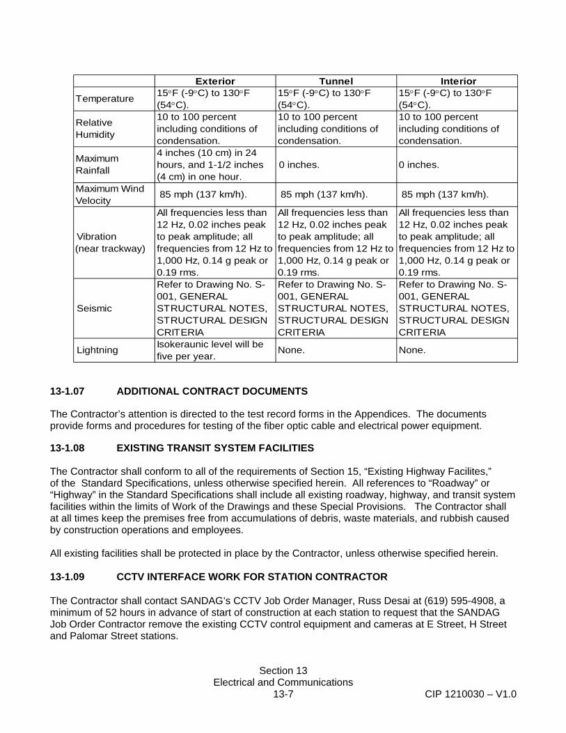
Section 13 Electrical and Communications
13-7 CIP 1210030 – V1.0
13-1.07 ADDITIONAL CONTRACT DOCUMENTS
The Contractor’s attention is directed to the test record forms in the Appendices. The documents provide forms and procedures for testing of the fiber optic cable and electrical power equipment.
13-1.08 EXISTING TRANSIT SYSTEM FACILITIES The Contractor shall conform to all of the requirements of Section 15, “Existing Highway Facilites,” of the Standard Specifications, unless otherwise specified herein. All references to “Roadway” or “Highway” in the Standard Specifications shall include all existing roadway, highway, and transit system facilities within the limits of Work of the Drawings and these Special Provisions. The Contractor shall at all times keep the premises free from accumulations of debris, waste materials, and rubbish caused by construction operations and employees. All existing facilities shall be protected in place by the Contractor, unless otherwise specified herein. 13-1.09 CCTV INTERFACE WORK FOR STATION CONTRACTOR The Contractor shall contact SANDAG’s CCTV Job Order Manager, Russ Desai at (619) 595-4908, a minimum of 52 hours in advance of start of construction at each station to request that the SANDAG Job Order Contractor remove the existing CCTV control equipment and cameras at E Street, H Street and Palomar Street stations.
Exterior Tunnel Interior
Temperature 15°F (-9°C) to 130°F (54°C).
15°F (-9°C) to 130°F (54°C).
15°F (-9°C) to 130°F (54°C).
Relative Humidity
10 to 100 percent including conditions of condensation.
10 to 100 percent including conditions of condensation.
10 to 100 percent including conditions of condensation.
Maximum Rainfall
4 inches (10 cm) in 24 hours, and 1-1/2 inches (4 cm) in one hour.
0 inches. 0 inches.
Maximum Wind Velocity
85 mph (137 km/h). 85 mph (137 km/h). 85 mph (137 km/h).
Vibration (near trackway)
All frequencies less than 12 Hz, 0.02 inches peak to peak amplitude; all frequencies from 12 Hz to 1,000 Hz, 0.14 g peak or 0.19 rms.
All frequencies less than 12 Hz, 0.02 inches peak to peak amplitude; all frequencies from 12 Hz to 1,000 Hz, 0.14 g peak or 0.19 rms.
All frequencies less than 12 Hz, 0.02 inches peak to peak amplitude; all frequencies from 12 Hz to 1,000 Hz, 0.14 g peak or 0.19 rms.
Seismic
Refer to Drawing No. S-001, GENERAL STRUCTURAL NOTES, STRUCTURAL DESIGN CRITERIA
Refer to Drawing No. S-001, GENERAL STRUCTURAL NOTES, STRUCTURAL DESIGN CRITERIA
Refer to Drawing No. S-001, GENERAL STRUCTURAL NOTES, STRUCTURAL DESIGN CRITERIA
Lightning Isokeraunic level will be five per year.
None. None.

Section 13 Electrical and Communications
13-8 CIP 1210030 – V1.0
The Contractor shall furnish and install conduit raceways from the Communications Cabinet to each camera location on the station platform and in the station parking lot as shown in plans. Prior to installing the cables, meet with CCTV contractor and CCTV Job Order Manager and security to confirm cable type to be used and final location for each camera at station platform and parking lot. Furnish 12 strand single mode fiber optic cable for each camera and install it from communications cabinet to each camera on the platform and parking lot as shown on the plans and in accordance with the single mode fiber optic cable requirements specified herein. Furnish and install CCTV power supplies and CCTV power supply cable as shown on the plans and as specified herein. Provide a single gang box on camera pole with 3’ long ¾” flexible conduit. Coordinate final height of box with CCTV Job Order Manager. Run fiber optic cable and camera power supply cable through flex conduit and leave 3’ of cable and power wires coiled hanging on the pole for CCTV contractor to connect it to camera. Terminate two strand of the fiber on to SC type connector for each camera. Furnish and install hardened media converter in accordance with the requirements specified herein. Test each fiber optic cable from camera to communications cabinet per test procedure described in the specifications and provide one set of test data to CCTV contractor who will connect CCTV equipment with the cameras. Within 48 hours of completing construction work activities at each station, the Contractor shall contact SANDAG’s CCTV Job Order Manager, Russ Desai at (619) 595-4908 to request that the SANDAG Job Order Contractor return to the station to reinstall the CCTV control equipment and cameras at the station. The Contractor shall incorporate CCTV as-built information provided by the SANDAG CCTV Job Order Contractor into the Station As-built plan set to be submitted by the Contractor to SANDAG. Full compensation for CCTV interface work shall be considered as included in the prices paid for the Electrical and Communication facilities work and no additional compensation will be allowed therefor.
13-1.10 MEASUREMENT AND PAYMENT Full compensation for complying with the requirements of Section 13-1, “General,” not otherwise provided for, shall be considered included in the contract prices paid for various items of work involved and no additional compensation will be allowed therefore. 13-2 ENGINEERING AND DESIGN SUBMITTALS Unless otherwise specified in this section, submittals shall conform to the requirements of Section 5-1.02, "Plans, Working Drawings, and Submittals," of these Special Provisions.
Section 13 Electrical and Communications
13-9 CIP 1210030 – V1.0
13-2.01 SITE INVESTIGATION AND DESIGN VERIFICATION A. The Contractor shall perform all necessary work including, but not limited to, field surveying,
blowing out conduits, installing pull ropes, identifying conduits and conduit runs, reviewing pull box sizing and existing conduit bend radius, determining conduit fill, to locate the complete fiber optic route and determine each fiber-optic cable run length. Locate the route and length of new conduit to be installed as shown on the plans.
Contractor shall locate all existing SDTI and Verizon Business (formerly MFS) underground facilities in the areas in which the Contractor will be digging. The Contractor shall make arrangements for a site meeting to mark out the existing facilities with Fred Byle of San Diego Trolley, at 619-595-4937, a minimum of 48 hours in advance of marking out the existing facilities. The Contractor shall open existing pull boxes and vaults as needed and locate the existing conduits and facilities. San Diego Trolley staff may, at their sole discretion, provide assistance in locating the facilities. The Contractor or company shall have had experience marking out SANDAG/SDTI facilities. One such company is Cable, Pipe, and Leak (CPL) at (619) 660-0844. Contractor shall pothole and protect in place existing Railroad Signaling Conduits, Pull Boxes, Cables, and equipment.
B. The Contractor shall protect in place all existing MTS facilities, unless otherwise directed on the
plans or in these Special Provisions. C. Contractor shall verify through field investigation the feasibility of the installing the system in
conformance with the plans, Special Provisions and Standard Specifications, prior to ordering material and beginning construction.
13-2.02 ENGINEERING DESIGN SUBMITTALS A. General: This Contract includes the submittal of certain documentation to SANDAG prior to and
subsequent to performance of the Work. All Submittals shall be provided to SANDAG for review and approval. If required, the Contractor shall make any changes to the Submittals as directed by SANDAG and resubmit. No Work requiring a Submittal shall commence until SANDAG’s approval has been obtained. SANDAG’s review of submittals will be based on determining whether the Work covered by the Submittal is in compliance with the Contract Documents. Any deviations from the requirements of the Contract Documents shall be called to the attention of SANDAG in writing on the Submittal, and shall not be accepted unless acknowledged in writing by SANDAG.
In addition to the requirements specified in Section 5-1.02, “Plans and Working Drawings,” of these Special Provisions, the Contractor shall submit to the Engineer for approval Drawings and technical data in the English language required for the manufacture and installation of facilities specified herein. The Contractor’s attention is drawn to the fact that the drawings indicate the final configuration of the fiber-optic cable to be installed and tested under this Contract. The Contractor may request permission to use equivalent materials. All requests shall be processed in conformance with Section 6-1.05, “Trade Names and Alternatives,” of these Special Provisions.

Section 13 Electrical and Communications
13-10 CIP 1210030 – V1.0
The Drawings and data shall show design dimensions, connections, material type, and other details necessary to assure that the Drawings are accurately interpreted. All requests for approval of material and equipment, and submissions of Drawings and data shall indicate the corresponding number of the Section and Paragraph of the Special Provisions and reference to the Drawing numbers under which each of the above are required. Individual Drawing numbers shall be assigned to each Drawing produced and shall be identified clearly in the title block. Revision numbers shall be shown on the Drawing and shall be dated. Each Drawing shall have a title block identifying the Client (SANDAG), the project title, the Capital Improvement Project (CIP) number (CIP 1210030), the Drawing contents, and the Contractor’s name. Standard ANSI and IEEE device symbols and nomenclature shall be used on Drawings. Standards between organizations shall not be combined on one Drawing.
B. Design Submittals: Within 40 calendar days following NTP and prior to the ordering of
equipment and material, the Contractor shall furnish to the Engineer six sets of complete material submittal drawings and any other pertinent data for approval of the Contractor’s design and the type of material, apparatus and equipment to be furnished. One of the Drawing sets shall be reproducible and the prints shall be blue line or black line on a white background. The installation is not considered to have met the requirements of this Section until all communication and electrical wires are terminated, tested, and neatly arranged and laced.
Detailed requirements for Design Submittals are as follows: 1. The Contractor shall provide, with all submitted Drawings, two (2) copies of an updated
Drawing Control Document. The Drawing Control Document shall contain the current transmittal date, the Contract Number, the Contractor’s name, the Drawing number, dates of previous submittals of the Drawings and a brief description of the revisions made.
2. The Engineer will return a copy of the data or Drawings received for review or approval,
with his comments, to the Contractor within 30 days.
3. Drawings submitted for review and returned with comments by the Engineer shall be resubmitted by the Contractor, incorporating the Engineer’s comments, within 30 days.
4. The Contractor shall submit catalog data, Drawings, and proofs of compliance with
applicable standards for the type of material he intends to supply and install within 30 days after Notice to Proceed.
Electrical enclosures and equipment shall be designed and installed with brackets and bolt downs to a reinforced concrete slab and shall comply with the seismic requirements indicated in the STRUCTURAL DESIGN CRITERIA, Drawing No. S-001 GENERAL STRUCTURAL NOTES. Submit seismic anchorage and bracing calculations sealed and signed by a professional engineer.
Section 13 Electrical and Communications
13-11 CIP 1210030 – V1.0
The Contractor shall submit mechanical Drawings and/or shop Drawings of all equipment to be delivered and installed to the Engineer for his approval in advance of manufacture so that an orderly processing of the Drawings, with the necessary approval, may occur prior to the manufacture of the equipment.
The Contractor shall submit within thirty (30) days after final termination of all electrical and communication cables at each location, in service final termination and equipment diagrams of all of the equipment installed.
Contractor shall furnish and install electrical system at new electrical service enclosure locations shown on the plans that supply power to the existing and new electrical circuits in conformance the requirements specified in the National Electrical Code (NEC), Special Provisions, and as shown on the contract drawings.
The Contractor’s submittal shall show all of the existing circuits in each panel and all changes to existing and new circuits required to balance the loads on each line (phase) in the new service enclosure. The Contractor shall submit a complete single line diagram identifying all changes to be made at each site. The single line diagram shall show all wire terminations, wire sizes, circuit breaker sizes, connections to each bus bar, etc. All breakers shall be numbered. The Contractor shall submit a breaker schedule that describes the connected load to each breaker, breaker number, connected load, and the bus bar. The Contractor shall confirm that all circuit breakers are properly sized to protect the existing circuits in conformance with the NEC Requirements. If the Contractor were to determine that a breaker was improperly sized, then the Contractor shall identify and note the change to the circuit on the electrical enclosure material submittal.
The Contractor shall provide dedicated circuits as shown on the drawings. No other loads shall be placed on the dedicated circuits.
The Contractor shall submit to the Engineer the manufacturer’s electrical and mechanical drawings that show unit dimensions, weights, component and connection locations, mounting provisions, connection details and wiring diagrams for each new electrical service location. The Contractor shall submit a certificate of compliance that demonstrates product conformance with these Special Provisions requirements. The Contractor shall submit a test procedure a minimum of 20 working days prior to testing and keep records of test results and measurements taken during testing of the system and submit them in a test record submittal.
13-2.03 RECOMMENDED INSTALLATION METHODS SUBMITTALS All work shall be installed in conformance with the manufacturer’s recommended installation methods, unless otherwise specified herein or directed by the Engineer. The Contractor shall submit the manufacturer’s recommended installation procedures or methods for all materials to be installed to the Engineer prior to the start of installation of any material. If the manufacturer’s recommended installation methods conflict with requirements specified in these Special Provisions or shown on the
Section 13 Electrical and Communications
13-12 CIP 1210030 – V1.0
plans, then the Contractor shall bring the conflict to the attention of the Engineer, or his designated representative, and request direction on how to proceed. If the manufacturer does not have recommended installation procedures or methods for the materials furnished, then the Contractor shall submit a copy of the correspondence to the manufacture in which the Contractor requested the information, the response the Contractor received from the manufacturer, and a description of the best workmanship methods the Contractor intends to follow. After the Engineer receives copies of the correspondence, the Engineer may authorize the Contractor to proceed with the installation of the material utilizing the best workmanship practices described by the Contractor. 13-2.04 FINAL DISTRIBUTION SUBMITTALS A. As Built Drawings
1. Within thirty (30) days after all new equipment and communication cables have been
installed and before issuance of Station Substantial Completion, the Contractor shall submit a complete set of final As-Built Drawings to the Engineer.
2. The final As-Built Drawings shall be produced by a computer aided drafting (CAD)
system. Minimum letter height shall be 0.10 inches. The Contractor shall submit, for the Engineer’s approval, a sample drawing he intends to use. The final As-Builts shall be supplied on a Compact Disk and in drawing form.
3. The final As-Built Drawings shall be “D” size (22 inches by 34 inches), unless authorized by the Engineer to substitute another size.
4. The final As-Built Drawings submitted shall include: (1) an index; (2) location Drawings drawn to a scale of one inch equals forty feet (1” = 40’); (3) detailed wiring diagrams of all equipment; (4) detailed and complete circuit Drawings; (5) cable Drawings; (6) conduit installation Drawings; (7) shop Drawings of equipment; and (8) material list.
5. The index shall show the title and sheet number of the Drawing.
6. Each circuit that continues on another Drawing shall be bracketed and noted with Drawing number and routing information for the continuation of the circuit.
7. The circuit Drawings shall show all individual circuits. Typical circuits will not be accepted.
8. The location Drawings shall show all cable installed with the number of conductors/ fibers, the size of conductors, the type of cable, termination points of conductors/fibers, and the circuit on each conductor. Separate cable Drawings shall be drawn if cable information cannot be shown in a neat and organized manner on the location Drawings.
9. The shop Drawings shall be detailed equipment drawings for each type of equipment installed.
10. The material list shall show the part number, part name, and a brief description of the part.
Section 13 Electrical and Communications
13-13 CIP 1210030 – V1.0
11. Each sheet of the final As-Built Drawings shall have a unique number assigned to the Drawing.
B. Unless otherwise specified herein the Contractor shall submit all of the following documentation to the Engineer within 30 days following the completion of work;
1. List of Electrical Panels, Circuits and Ratings. 2. Patch Panel documentation and complete Patch Panel Forms. 3. Test Reports as described in Section 13-5 “Testing” and various other sections of these
Special Provisions.
C. Operating and Equipment Manuals (O&M) Submittals
Within thirty (30) days after new equipment is installed and prior to Contract acceptance, the Contractor shall submit to the Engineer, six (6) sets each of installation, operating and maintenance manuals of all equipment and systems utilized under this Contract.
13-2.05 EQUIPMENT LIST AND DRAWINGS Section 86-1.04, “Equipment List and Drawings,” of the Standard Specifications shall not apply. 13-2.06 PARTS LIST The Contractor shall submit complete ordering information on all assemblies and subassemblies. These lists shall be grouped by system and subsystem and include component name, description, current price, rating accuracy, manufacturer’s name, part number, and material reference number.
13-2.07 WARRANTIES, GUARANTEES, AND INSTRUCTION SHEETS A. Warranties, guarantees, and instruction sheets shall conform to the provisions in Section
86-1.05, “Warranties, Guarantees and Instructions Sheets,” of the Standard Specifications. B. Compliance Submittals: The following compliance documents shall be submitted within 24 days
following the Notice to Proceed:
1. Personnel Qualifications: Submit qualifications for personnel who will be performing any installation, testing, splicing, or termination of fiber and electrical construction. No personnel will be allowed to do Work until qualifications have been approved. Submit two sets of copies to the Engineer.
2. Tools and Test Equipment List: Provide a list of all tools and test equipment (major
items only) that will be used in the performance of the Work, including make, model, description, and use. Obtain approval prior to commencing Work. Submit two sets of copies to the Engineer.
3. Catalog cuts and specifications for all Contractor-furnished equipment and materials.
Section 13 Electrical and Communications
13-14 CIP 1210030 – V1.0
13-3 MATERIALS General
All materials shall conform to the provisions of Section 86, “Signals, Lighting and Electrical Systems, “of the Standard Specifications unless otherwise specified herein. The Contractor shall conform to Section 4, “Scope of Work” and Section 5, “Control of Work” of the Standard Specifications, and Section 7-5.08, “Buy America,” of these Special Provisions. The Contractor shall submit for approval all materials prior to purchase and within 30 working days following Notice To Proceed (NTP). The Contractor’s submittal shall identify any and all deviations from the Drawings, Standard Specifications or Special Provisions. The Contractor shall not purchase any materials that deviate from the Drawings, Standard Specifications or Special Provisions, unless the Engineer in writing approves the deviation. The Contractor shall submit all requests for deviation to the Engineer in writing.
The Contractor shall furnish all equipment, materials, and accessories required to complete the installation and testing of the electrical and communication system as indicated. All materials shall be new products of manufacturers regularly engaged in the production of such materials and equipment, and shall be the manufacturers’ latest approved design.
All materials and equipment provided by the Contractor shall be new. All materials and equipment for installation and for interconnection of the various systems shall be fabricated, furnished, and installed as indicated on the Contract Drawings and specified herein. All “or equal” equipment or materials, not shown on the Contract Drawings but proposed by the Contractor, shall have shown proven performance in the United States of America for a minimum of 1 year. Materials and equipment shall be delivered to the jobsite in unbroken packages, reels, or other forms of containers. Reference to specific equipment and/or manufacturers is intended to establish quality, overall design, and fit, subject to compliance with all criteria specifications. Certain equipment shown in the Contract Drawings and indicated in the Specification must be installed to ensure compatibility with the existing system. Equipment equal to, or exceeding the Specifications and requirements may be used subject to the Engineer's written acceptance. Should alternate equipment be accepted, the Contractor shall perform all necessary work to fit the alternate equipment to these Specifications and to revise the Contract Drawings at no additional cost to SANDAG. GENERAL ELECTRICAL AND ELECTRONIC COMPONENT REQUIREMENTS Unless otherwise specified herein, the Contractor shall furnish breakers of all DC power supplies and circuitry according to the following requirements: A. Circuit breakers shall be the correct rating for circuit current interruption.
B. Circuit breakers shall be sized to protect the wire.
C. Circuit breakers shall be in the positive leg of the power supply.
D. Circuit breakers shall be of the nonrenewable indicating type.
E. All branch feeds for a circuit shall be from the same breaker.
F. Breakers shall be no smaller than 5 amperes unless otherwise shown on the Drawings.
G. Loads shall be divided so that no normal operating current is more than 75 percent of the breaker rating.
Section 13 Electrical and Communications
13-15 CIP 1210030 – V1.0
H. Breakers shall be functionally oriented to minimize the equipment affected by a tripped breaker.
Printed Circuit (PC) Cards and Connectors shall be as specified in the following: A. The PC cards shall be mounted in 19-inch card files unless otherwise approved by the
Engineer.
B. The PC wiring shall be organized so that wires serving the same function shall be connected to the same terminal of PC cards. PC cards containing the same circuitry and programming, where applicable, shall be interchangeable between subsystems.
C. The design and construction of PC cards of the same subsystems shall be the same. Cards of different subsystems shall be of the same design and construction wherever practicable.
D. PC cards shall be of glass epoxy construction. Card material shall meet the requirements of NEMA, Type FR-4. Cards shall have sufficient thickness to permit easy insertion and removal, and shall be physically keyed to protect against incorrect interchange. Circuits shall be formed by etching. Conductor material shall be copper and shall be protected from exposure to air.
E. PC cards containing components that may be damaged if a plug connector or plug-in unit is removed while the equipment is energized shall be clearly identified in the equipment maintenance manual. PC 9 Revision/Addendum No. 2+) cards shall be marked or labeled with a warning note on the individual board, be conspicuously located on the module, or by an alternate means as approved by the Engineer. A means shall be provided to remove power from the module or card file.
F. Components mounted on the PC card, weighing more than 1/2 ounce or with a displacement greater than 1/2 cubic inch, shall have a mechanical supporting attachment to the card separate from all electrical connections.
G. Stacking or piggybacking of PC sections in order to accomplish changes or modifications to wiring or components on printed circuit cards shall not be allowed.
H. Connectors shall have plating with a minimum thickness of 0.00005 inch. Unless otherwise specified herein, Printed Circuit card files shall be as specified in the following: A. There shall be not more than one type of card file for each size of PC card. The card file
plugboards shall be registered to agree with the registry of the associated PC card. PC cards shall not project beyond the front of the equipment rack when mounted in the card file.
B. Card files shall be installed in dustproof cabinets and protected with dust covers.
C. Insulated cable clamping devices shall be located on the back of the file in such a way that wires terminating in the files shall be installed in a neat and secure bundle, rigidly supported, and protected to prevent chafing of insulation. Cabling provision on the file shall permit wires to enter or leave the file from both the right and left sides. Such cabling shall not restrict access to the card file when the rear covers of the card files are removed prior to factory testing.
Full compensation for furnishing and installing miscellaneous material and equipment not described in the measurement and payment section of these Special Provisions shall be considered included in the contract price paid for the various items of work, and no additional compensation will be allowed therefore.
Section 13 Electrical and Communications
13-16 CIP 1210030 – V1.0
13-3.01 PLUG STRIPS - RACK MOUNTED POWER STRIPS
For all communications equipment requiring connection to a 120VAC power supply, connection shall be made to a 19 inch rack mountable power strip (1U in height).
The rack mountable power supply shall be from Giest Manufacturing (PM Series or RSM Series) Power Strip, Dataprobe iBootBar (Model No iBB-2020-M), or an approved equal, and shall be UL certified.
The power strip shall have a minimum of 6 NEMA 5-15R (or 5-20R) outlets on the front panel, and a minimum of 6 NEMA 5-15R (or 5-20R) outlets on the rear panel. The power strip must be capable of supplying a minimum of 20A, and shall have at least one hardwired power inlet, and input power cords shall be no less than 15 feet in length. The rack mountable power strip shall have on-board digital metering arrangements (Power, Voltage and Amperage), external LED indications for “Power On.” The Rack mountable power supply shall also have on board surge protection, and over current protection. External construction shall be Heavy duty powder coated steel
Environmental Operating parameters must meet or exceed those parameters as specified in Section 13-1.06. 13-3.02 MISCELLANEOUS STEEL AND IRON The final fabrication drawings for all assemblies shown shall be prepared by the manufacturer of the assembly and submitted to the Engineer for approval in accordance with Section 13-2.02, “Engineering Design Submittals,” and the strength requirements specified herein. Mounting hardware exposed to the elements shall be hot dip galvanized, or stainless steel, except as otherwise specified herein or approved by the Engineer. The hardware shall be coated as follows:
The hot dip process of galvanizing shall be used for coating of steel parts that are specified removed. The zinc coating shall be of commercially pure zinc, and shall be continuous and thorough. It shall not scale or blister, or be removable by any of the processes of handling or installation. The finished surface shall be free from fine line cracks, holes, or other indications of faulty galvanizing. It shall be smooth and free from adhering flux and other impurities. The edges and ends of parts shall be free from lumps and globules. Parts shall be coated with at least 2 ounces of zinc per square foot for galvanized surface after all bending, cutting, drilling, and final fabrication.
Nuts, bolts, and washers used to mount equipment with in finished enclosures shall be stainless steel. As an alternate, the Contractor may submit another type of plating or non-corroding metal for the Engineer's approval.
Lock washers shall be cadmium plated. Cadmium plating shall be an impervious, dense, hard, fine-grained, continuous, closely adhering coating of commercially pure cadmium, free from capillaries, and shall completely cover the surface of the part in a smooth, bright layer. Plating on raised or prominent portions shall show no evidence of blackness or loose crystalline structure. It shall have a minimum thickness of six ten-thousandths of an inch and shall withstand the standard salt spray test for at least 1,000 hours or an equivalent test approved by the Engineer. Full compensation for furnishing steel and malleable iron shall be considered included in the contract prices paid for the various items of work and no separate payment will be allowed therefore.

Section 13 Electrical and Communications
13-17 CIP 1210030 – V1.0
13-3.03 CONCRETE All concrete shall conform to section 90-10, “Minor Concrete” of the Standard Specifications. 13-3.04 REINFORCING STEEL Bar reinforcing steel shall conform to the provisions in Section 52, “Reinforcement,” of the Standard Specifications. Full compensation for furnishing reinforcing steel shall be considered included in the contract prices paid fo rthe various related items of work and no separate payment will be allowed therefore. 13-3.05 FOUNDATIONS Foundations shall conform to the provisions in Section 86-2.03, “Foundations,” of the Standard Specifications and these special provisions. Concrete for foundations shall have not less than 564 pounds of cement per cubic yard. If a cast in-place foundation is used the bolt size and pattern and finish of the top of foundation shall be equivalent to the precast foundation shown in Part 14.4.3C of the AREMA Communications and Signaling Manual. 13-3.06 ASPHALT CONCRETE Asphalt Concrete shall conform to requirements of Section 39 “Asphalt Concrete” of the Standard Specifications. 13-3.07 GROUNDING MATERIALS Grounding materials shall be copper or copper alloy, corrosion-resistant, with high conductivity for ground systems. Fittings for slices, taps, and crosses or embedded conductors shall be suitable for exothermic welding of copper to copper conductors. Full compensation for furnishing grounding materials shall be considered included in the contract prices paid for the various items of work and no separate payment will be allowed therefore. 13-3.08 CONDUIT
Conduit shall be UL or ETL listed. Buried conduit shall be Caltrans Type 3, schedule 40 polyvinyl chloride (PVC) rigid non-metallic conduit conforming to the requirements in the UL Standard for Rigid Non-Metallic Conduit (Publication UL 651). Exposed conduit shall be Caltrans Type 1, hot-dip galvanized rigid steel conduit conforming to the requirements in UL Publication UL6 for Rigid Metallic Conduit. The zinc coating shall be capable of passing a test performed in conformance with ASTM Designation: A239. New conduit shall be sized as shown on the plans. If the conduit size is not provided on the plans for a new conduit run, then the conduit shall be a 3 inch diameter conduit.
Section 13 Electrical and Communications
13-18 CIP 1210030 – V1.0
Conduit identified on the plans as containing 500 MCM cables shall be fully encased in a minimum of 3 inches of red concrete measured perpendicular to the conduit surface. Surface mounted and I-beam supported conduit runs shall be attached to the surface with hot dipped galvanized steel framing channels and all associated fittings and hardware including, but not limited to, clamps, brackets, hanger rods, and fittings. Hardware shall be made of Type 304 or Type 316 stainless steel. Framing channels shall be secured to the surface with type 304 or 316 stainless steel mechanical wedge anchor fasteners that firmly anchor the channel to the surface in conformance with the manufacturers recommended installation procedures. The anchors shall be listed or approved by ICC (formerly ICBO) or UL .for this application. Spacing of the support shall conform to the manufacturer’s recommendations and shall not exceed five feet. Steel framing systems shall comply with UL 5, “Standards for Surface Metal Raceway and Fittings.” All steel framing systems attached to buildings shall conform to all applicable NEC and NFPA standards and requirements. Conduit run across roof surface shall be supported by a durable, ultraviolet resistant, flexible, polyethylene foam block with an integral galvanized steel channel that shall be used to clamp the conduit and additional hot dipped galvanized metal framing systems to it. All fasteners and hot dipped galvanized steel framing systems shall be UL listed and made of hot dipped galvanized steel. Spacing of the support shall conform to the manufacturer’s recommendations and shall not exceed five feet. All hardware shall be made of Type 304 or Type 316 stainless steel. Existing conduits terminated at the surface of the existing LRT platform shall be extended to the finish grade of the new improvements, and the plugs or caps replaced. 13-3.09 PULL BOXES A. PULL BOX EXTENSION
Where existing pull boxes are shown to be extended or adjusted to grade, the existing precast reinforced Portland cement concrete (PCC) pull boxes shall be extended as shown on the plans and the lid replaced with a traffic rated lid conforming to the requirements of section 86-2.07, "Traffic Pull Boxes," of the Standard Specifications, unless otherwise specified in the plans or Special Provisions. The pull box extension shall be constructed of reinforced PCC or galvanized steel and have a galvanized steel traffic rated lid with a z-bar frame conforming to Section 86-2.07, "Traffic Pull Boxes," of the Standard Specifications. The pull box extensions shall be designed to sit tightly inside the existing pull box lid recess and the new traffic rated lid shall sit within the pull box extension the same way the galvanized steel traffic rated cover sits in the pull box shown in Section A-A of Caltrans Standard Plan ES-8. The pull box extension shall be connected to the existing pull box using bolts or epoxy adhesive conforming to the requirements of Section 95, "Epoxy.” At the contractor's option, existing pull boxes shown to be extended may be replaced with a new pull box conforming to these Special Provisions.
Section 13 Electrical and Communications
13-19 CIP 1210030 – V1.0
B. NEW PULL BOXES
Where new pull boxes are shown on the plans to be installed, the Contractor shall furnish and install pull boxes as shown on the pull box schedule. All SDG&E Standard 3313 Handholes shall include the Steel Traffic Cover. The lid shall be marked “Communications” for communications handholes and marked “Electrical” for electrical handholes. Caltrans Standard traffic rated (T) pull boxes as shown on ES-8 of the State of California, Department of Transportation Standard Plans and shall conform to the requirements of Section 86-2.07, “Traffic Pull Boxes,” of the Standard Specifications and referenced sections of 86-2.06, “Pull Boxes,” of the Standard Specifications. Plastic pull boxes shall not be allowed.
13-3.10 POLE ATTACHMENT HARDWARE All pole mounting hardware and assemblies shall be made of hot dipped galvanized steel hardware conforming to Section 75 “Miscellaneous Metal” and Section 75-1.05, “Galvanizing,” of the Standard Specifications. All banding shall be made of type 304 or 316 stainless steel conforming to Section 75, “Miscellaneous Metal,” of the Standard Specifications. 13-3.11 WIRE AND CABLE MATERIALS The work shall consist of furnishing and installing wires and cables, cable, cable connectors, and other materials as referenced, but not specified in related Sections and as indicated on the plans. Wire and cable shall be installed in conduit. Splices will not be permitted in cables. Cables shall be continuous between all designed termination points. Raceways shall be thoroughly cleaned prior to installation to verify that no obstructions exist. No kinks in wire and cable will be permitted and bends shall be larger in radius than the minimum recommended by the manufacturer. Only those lubricants recommend by the wire and cable manufacturer shall be used for pulling cables. A. Electrical Wire
All electrical conductors shall conform to the requirements of Section 86-2.08, “Conductors,” as further defined in subsection 86-2.08B “Multiple Circuit Conductors,” and Articles 200, 210, 215, and 310 of the National Electrical Code. Unless otherwise shown on the plans, the conductors shall be copper conductors with type TW, THW, USE, RHH, or RHW insulation rated for 600 V AC and shall be the size shown on the plans or specified in these Special Provisions. If conductor sizing is not provided, then the conductors shall be sized by the contractor in conformance with National Electrical Code requirements and the manufacturers recommendations. All conductors shall be properly sized to provide power to the loads connected to the wires.
B. Insulated Jacketed Conductors Traction Power Cable
NOT USED
C. Audio Converter to Amplifier Cable
Section 13 Electrical and Communications
13-20 CIP 1210030 – V1.0
The audio converter to amplifier cable shall be a Caltrans Standard Type C Lead-in cable specified in Section 86-5.01A (4) of the Standard Specifications. Cable shall be 16 AWG stranded shielded twisted pair with an overall diameter not greater than 0.309 inches and conform to the requirements in International Municipal Signal Association (IMSA) Specification No. 50-2. A No. 20 AWG minimum, copper drain wire shall be provided.
D. Audio Speaker Cable
All Outdoor Speaker Cable shall be shielded twisted pair two conductor 19 strand, 12 AWG, 600 volt RMS cable (Belden part no. 603378 or approved equivalent). Conductor insulation shall be polyethylene. The conductors shall be fully covered with an aluminium foil shield and a black low-density polyethylene (LDPE) jacket. Cable shall conform to IMSA Specification 50-2 (1991), "Polyethylene Insulated, Polyethylene Jacketed, Loop Detector Lead-In Cable” requirements. Speaker cable connections to the amplifier shall use soldered end or spade lugs.
E. TWC Loop Connector Cable
The cable to be installed from the TWC Interogator to each TWC Loop shall be four conductor twisted pair shielded cable. The conductors shall be a 2-pair, #14 AWG, 19 strand, copper conductors, Advanced Digital Cable 8782A or approved equal. Conductor insulation shall be polyethylene. The conductors shall be fully covered with an aluminium foil shield and a black low-density polyethylene (LDPE) jacket. Cable shall conform to IMSA Specification 50-2 (1991), "Polyethylene Insulated, Polyethylene Jacketed, Loop Detector Lead-In Cable” requirements.
F. Ethernet UTP Cables
All UTP patch cords or patch cables to be installed within a communications enclosure shall be Commscope, Uniprise indoor rated Category 6 (CAT6) UTP strength through configuration blue jacket patch cord with RJ-45 factory installed connectors at both ends and conforming to the requirements of ANSI/TIA-568-B.2-1. Patch cords shall be installed to interconnect all communication interfaces between the network equipment as shown on the plans. The patch cords shall be factory made, and not spliced and terminated on-site. They shall come in standard lengths (e.g. 1 foot, 1.5 feet, 2 feet, 5 feet, and 10 feet). The patch cords shall have strain-relief RJ-45 connectors. The patch cords shall be rated as Category 6 unshielded twisted pair cabling, and shall terminate all eight conductor positions in both cable connectors. All Category 6 cables installed between the communications enclosure to a field device (VMS, TVM, or PCID), shall be outdoor rated CAT 6 Unshielded Twisted Pair (U/UTP) flooding compound filled cables conforming to the requirements of ANSI/TIA-568-C.2. Cable shall be Comscope Media 6, outdoor rated category 6 (CAT6) Unshielded Twisted Pair (U/UTP) flooding compound filled cable (Comscope Media 6, 6NF4+) or an approved equivalent. One end of the outdoor rated CAT 6 cable shall be terminated to the field device with a RJ-45 connector and the other end shall be terminated to the rack mounted CAT 6 patch panel in the Communications Enclosure. CAT 6 connector on the device end of the cable shall be Platinum Tools EZ-RJ45 Cat 6+ Connectors with EZ-RJ45 Strain Reliefs or approved equivalent. Connectors shall be UL rated, EIA/TIA B.2. FCC compliant, and shall be installed using the EZ-RJ45 Crimping tool or an equivalent tool recommended by the connector manufacturer. Connectors shall be installed in conformance with the manufacturers recommended installation instructions and all eight conductors of each cable conductors shall be terminated at both ends.
Section 13 Electrical and Communications
13-21 CIP 1210030 – V1.0
G. Tracer Wire
Tracer wire shall be No. 8 stranded, minimum, copper conductor with Type TW, THW, RHW, or USE insulation. The tracer wire shall be continuous from pullbox to pull box, enclosure, or pole. A minimum of 1.5 m of slack shall be coiled up in each pull box and fiber optic vault from each direction.
H. Fiber Optic Patch Cords
Single Mode Fiber Optic Patch Cords shall have connectors on the ends that are properly sized to fit within the connector ports of the equipment specified. Single mode fiber optic patch cords shall conform to the performance characteristics of the cables they will be connecting to. The lengths of the patch cord shall come in standard lengths (e.g., 1 foot, 1.5 feet, 2 feet, 5 feet, 10 feet). Cables shall be as short as required to make the connection and be properly laced as described elsewhere in these Special Provisions.
I. Fiber Optic Cable
The Fiber-optic cable furnished and installed by the Contractor shall comply with the following Specifications.
General Fiber Optic Cable Requirements
Outdoor, Loose Tube, Fiber-Optic Cable shall be constructed with loose buffer tubes containing fibers in the quantities specified and indicated. All fiber-optic cable shall be from the same manufacturer. Cable shall meet or exceed the following specifications and conform with the latest issue of ICEA S-104-696 Standard for Indoor-Outdoor Optical Fiber Cable. The loose tube cables shall comply with the optical and mechanical requirements over an operating temperature range of -40°C to +70°C. The cable shall be tested in accordance with EIA-455-3A (FOTP-3), “Procedure to Measure Temperature Cycling Effects on Optical Fiber, Optical Cable, and Other Passive Fiber Optic Components.” The change in optical attenuation at extreme operational temperature (-40°C to +70°C) for single mode fiber shall not be greater than 0.20 dB/km, with 80 percent of the measured values no greater than 0.15 dB/km. The single mode fiber measurement is made at 1550 nm. Materials used within a given cable shall be compatible with all other materials used in the same cable when such materials come into contact. All cable components used shall not adversly effect the optical transmission or the mechanical integrity of the fiber placed in the cable. All materials used shall be non-toxic, non-corrosive, and shall present no dermal hazard. Cable shall be manufactured continuous with no factory splices in the fiber. The fiber optic cable shall not be adversly effected by the following mechanical and environmental conditions. a. Crush Resistance:
The cable shall not be crushed by a 10,000 N/m (6.78 lb/ft) load.
Section 13 Electrical and Communications
13-22 CIP 1210030 – V1.0
b. Minimum Bending Radius The cable shall be designed for a minimum bending radius of:
(1) Installation (Loaded): 20 x cable diameter (2) Static (Installed): 10 x cable diameter
c. Temperature:
(1) Operational: -40 to +70C (2) Storage: -40 to +70C
d. Humidity: 0 to 100%
e. Tensile Strength: The cable shall not be damaged under the following tensile load:
(1) Installation: 2,700 N (600 lbf) (2) Static: 600 N (135 lbf)
Cables shall withstand an installation tensile load of not less than 600 pounds force and not less than 200 pounds force continuous tensile load. When tested in accordance with FOTP-33, "Fiber-optic cable Tensile Loading and Bending Test," and FOTP-38, “Measurement of Fiber Strain in Cables Under Tensile Load,” a length of cable shall be tested to the rated tensile load. The rated tensile load shall be 2670 N (600 lbf). While under the rated tensile load, the fiber shall not experience a measured fiber strain greater than 60% of the fiber proof test level. After being held at the residual load (30% of the rated tensile load) the fiber shall not experience a measured fiber strain greater than 20% of the fiber proof test level nor an attenuation change greater than 0.15 dB at 1550 nm (single-mode). After the tensile load is removed, the fibers shall not experience an attenuation change greater than 0.40 dB at 1550 nm (single-mode). The cables shall withstand an impact of 1.5 lbs/in as a minimum, and shall have a crush resistance of 300 pounds per square inch as a minimum. When tested in accordance with FOTP-25, "Repeated Impact Testing of Fiber-optic cables and Cable Assemblies," the cable shall withstand a minimum of 2 impact cycles at 3 locations separated by at least 150 mm. The impact energy shall be 4.4 N•m. The fibers shall not experience an attenuation change greater than 0.40 dB at 1550 nm (single-mode) or greater than 0.60 dB at 1300 nm (multimode). The presence of visible cracks, splits, tears, or other openings on the outer surface of the jacket constitute a failure
f. Compressive Load: When tested in accordance with FOTP-41, "Compressive Loading Resistance of Fiber-optic cables," the cable shall withstand a minimum compressive load of 220 N/cm (125 lbf/in) applied uniformly over the length of the sample. The 220 N/cm (125 lbf/in) load shall be applied at a rate of 2.5 mm (0.1 in) per minute. The load shall be maintained for a period of 1 minute. The load shall then be decreased to 110 N/cm (63 lbf/in). Alternatively, it is acceptable to remove the 220 N/cm (125 lbf/in) load entirely and apply the 110 N/cm (63 lbf/in) load within five minutes at a rate of 2.5 mm (0.1 in) per minute. The 110 N/cm (63 lbf/in) load shall be maintained for a period of 10 minutes. Attenuation measurements shall be performed before release of the 110 N/cm (63 lbf/in) load. The change in attenuation shall not exceed 0.15 dB at 1550 nm for single-mode fibers.
g. All fiber optic cables shall be all dielectric.
Section 13 Electrical and Communications
13-23 CIP 1210030 – V1.0
h. All fiber optic cables shall contain single mode fibers conforming the the requirements
specified below. (1) Each optical fiber shall be glass and consist of a doped silica core surrounded by
concentric silica cladding. All fibers in the buffer tube shall be usable fibers, and shall be sufficiently free of surface imperfections and inclusions to meet the optical, mechanical, and environmental requirements of these Specifications. The required fiber grade SM shall reflect the maximum individual fiber attenuation, to guarantee the required performance of each and every fiber in the cable.
(2) The single mode FOC shall comply with TIA /EIA 492-CAAB and the following
optical specifications including the zero water peak. (3) Operational Wavelengths: 1,310 nm, 1383 nm and 1,550 nm (4) Optical Attenuation:
For all fibers the attenuation specification shall be a maximum attenuation for each fiber over the entire operating temperature range of the cable. (1) @ 1,310 nm, 20 C: less than 0.38 dB/km (2) @ 1,383 nm, 20 C: less than 0.36 dB/km (3) @ 1,550 nm, 20 C: less than 0.26 dB/km
(5) Optical fibers shall be single-mode (SM) step index optical glass wave-guides
with a nominal core diameter of 8 to 9 microns. The fiber shall have a transmission window centered at 1310 nanometer (nm) wavelength and an optical window from 1300 to 1600 nm.
(6) Cladding diameter shall be 125 microns plus or minus 3 microns. Core cladding
offset shall be less than 1 micron. Minimum tensile strength of the fiber after primary protective coating shall be greater than 100,000 psi. Softening point of the clad material of the optical fiber shall be 1630 degrees C plus or minus 50 degrees.
(7) Optical fiber shall be coated with suitable material to preserve the intrinsic high
tensile strength of the glass fiber. Outside diameter of the coated optical fiber shall be 250 plus or minus 15 microns. Coating material shall be readily removable, mechanically or chemically, without damaging the optical fibers when the removal is desired. The coating of each optical fiber shall be a dual layered, UV cured acrylate. The coating shall be mechanically or chemically strippable without damaging the fiber.
(8) Each fiber shall be distinguishable by means of color-coding in accordance with
TIA/EIA-598-A, “Optical Fiber Cable Color Coding” and shall be targeted in accordance with the Munsell color shades. The color formulation shall be compatible with the fiber coating and the buffer tube filling compound, and be heat stable. In buffer tubes containing multiple fibers, the colors shall be stable across the specified storage and operating temperature range and not subject to fading or smearing onto each other or into the gel filling material. Colors shall not cause fibers to stick together.
Section 13 Electrical and Communications
13-24 CIP 1210030 – V1.0
(9) Optical fibers shall be distinguishable from others in the same buffer tube by
means of color coding according to the following:
1. Blue (BL) 7. Red (RD) 2. Orange (OR) 8. Black (BK) 3. Green (GR) 9. Yellow (YL) 4. Brown (BR) 10. Violet (VL) 5. Slate (SL) 11. Rose (RS) 6. White (WT) 12. Aqua (AQ)
i. 12 Strand Fiber Optic Cable: All 12 strand FOC shall be all dielectric and conform to the
following requirements:
(1) Stranding The 12 strand FOC shall have 12 individual glass fibers in a single blue buffer tube.
(2) Buffer tube
Loose buffer tubes shall provide clearance between the fibers and the inside of the tube to allow for expansion without constraining the fiber. The fibers shall be loose or suspended within the tubes and shall not adhere to the inside of the tube. The loose buffer tubes shall be extruded from a material having a coefficient of friction sufficiently low to allow free movement of the fibers. The material shall be tough and abrasion resistant to provide mechanical and environmental protection of the fibers, yet designed to permit safe intentional “scoring” and breakout, without damaging or degrading the internal fibers. Buffer tube filling compound shall be a homogenous hydrocarbon-based gel with anti-oxidant additives and used to prevent water intrusion and migration. The filling compound shall be non-toxic and safe to exposed skin. It shall be chemically and mechanically compatible with all cable components, non-nutritive to fungus, non-hygroscopic and electrically non-conductive. The filling compound shall be free from dirt and foreign matter and shall be readily removable with conventional nontoxic solvents.
(3) Dry Core, Water Blocking and Dielectric strength member
Cable shall have dry core buffer tube with water swellable strength member surrounding the core buffer tube to prevent water migration. Tensile strength shall be provided by high tensile strength aramid yarns or fiberglass which shall be placed evenly around the cable core buffer tube and shall not adhere to other cable components. The water blocking tape and strength member may be a single or multiple layer(s).
(4) Ripcord
The cable shall have a ripcord enabling the jacket to be split.
Section 13 Electrical and Communications
13-25 CIP 1210030 – V1.0
(5) Outer jacket
Cable jacket shall be marked with manufacturer’s name, sequential meter or foot markings, date of manufacture and a telecommunication handset symbol, as required by Section 350G of the National Electrical Safety Code (NESC). The markings shall be in contrasting color to the cable jacket. Cable jacketing for exterior and aerial installations shall be medium density polyethylene material containing at least 2.6 percent carbon black with only black pigment added for coloring. Jacketing for interior/exterior rated cable shall be UV-resistant polyvinyl chloride (PVC), which complies with optical fiber nonconductive riser (OFNR) requirements.
(6) Maximum Cable Diameter
The cable diameter shall not exceed 7.7 mm (0.30 inches).
J. CAMERA POWER SUPPLY CABLE
The camera power supply cable shall be a PVC jacketed, Type MC cable rated for installation in a wet environment. The conductors shall be soft-drawn copper, Type THHN/THWN, 600 volt rated. The conductors shall be cabled together with a binder tape, wrapped around the assembly, which is covered by a aluminum interlocking armor. A flame retardant, sunlight resistant, PVC jacket is then applied over the armor.
13-3.12 CABLE TAGS Cable tags shall conform to the following requirements: A. Each end of every patch cord, fiber optic cable, UTP cable, and speaker cable shall be labeled
with Allied Electric Self-Laminating Laser Tag labels (Manufacturer’s number TAG5L-105) or an approved equivalent.
B. Each label shall contain the end device name (e.g. “VMS-SB1,” “TWC-SB1,” etc.), the near end termination port identification (e.g. “ES-C3” (Gigabit Ethernet Switch, port C3)) and the far end termination port identification at the other end of the cable (e.g., “16MC-1” (16 Bay Media Converter, port 1). Contractor shall submit proposed device naming convention and port identification naming conventions for approval.
C. Tagging formats and administrative records shall be maintained for all cables. Tagging formats
and administrative records shall be created following an approach that is similar to EIA/TIA-606 standard practices. Nomenclature shall be consistent with naming conventions shown on the plans. Labels shall be concise and preferably diagrammatic in form. All labels or number plates and warning notices shall have black lettering on a white background. The size of the letters and the nature of the wording shall be submitted by Contractor. All conductor wires and cables shall be identified whenever they enter or leave a junction box, manhole, housing, or enclosure, and at all terminals.
D. All labels, number plates and warning notices shall be of durable and corrosion resistant
materials securely fitted by permanent means and clearly worded. For outdoor use they shall
Section 13 Electrical and Communications
13-26 CIP 1210030 – V1.0
remain legible and not suffer degradation throughout the expected life of the equipment. All wires and cables shall be tagged during the termination process, as specified herein.
E. Permanent non-conducting marking tags fastened securely to the wires and cables shall be
used for identification. Wire designations shall consistently conform to an overall scheme prepared by SANDAG. The Contractor shall develop detailed labeling and administrative records that indicate location, circuit, device, wire number, terminal branch, and position, etc. Letters and numbers shall be used.
13-3.13 FIBER OPTIC TERMINATIONS General All components shall be the size and type required for the specified fiber. Cable assemblies (jumpers and pigtails) shall be products of the same manufacturer. The cable used for cable assemblies shall be made of fiber meeting the performance requirements fo these special provisions for the FOC being connected. Jumpers Jumpers may be of simplex or duplex design. Duplex jumpers shall be of duplex round cable construction and shall not have zipcord (siamese) construction. All jumpers shall be at least 2 meters in length, sufficient fo avoid stress and allow orderly routing. The outer jacket of duplex jumpers shall be colored according to the single mode color (yellow) specified. The two innner simplex jackets shall be contrasting colors to provide easy visual identification for polarity. Connectors Fiber optic connectors shall be ceramic ferrule SC Duplex type for single mode fiber. Indoor SC Duplex connector body housings shall be either nickel plated zinc or glass reinforced polymer construction. Outdoor SC Duplex connector body housing shall be glass reinforced polymer. The associated coupler shall be of the same material as the connector housing. All FOC connnectors shall be the 2.5 mm SC Duplex connector ferrule type with Zirconia Ceramic material with the Physical Contact (PC) pre-radiused tip. The SC Duplex connector operating temperature range shall be -40ºF (-40ºC) to 158ºF (+70ºC). Insertion loss shall not exceed 0.4 dB for single mode, and the return reflection loss on single mode connectors shall be at least 55 dB. Connection durability shall be less than a 0.2 dB change per 500 mating cycles per EIA-455-21A (FOTP-21). All terminations shall provide a minimum 50 lb (222 N) pull out strength. Single mode connnectors shall have a yellow color on the body and/or boot that renders them easily identifiable. Field terminations shall be limited to splicing of adjoining cable ends and/or cables to SC pigtails. Fiber optic connectors shall be factory installed onto pigtails to be fusion spliced to the FOC in the field.
The cable used for pigtails shall be made of fiber meeting the performance requirements of these special provisions for the fiber-optic cable being connected. The connector housing shall be composite and the alignment ferrule shall be ceramic.
Section 13 Electrical and Communications
13-27 CIP 1210030 – V1.0
Connector insertion loss shall be nominally 0.3dB and guaranteed less than 0.5dB, reflectance less than -55dB. 13-3.14 FIBER DISTRIBUTION UNIT (FDU) The Contractor shall furnish fiber distribution unit (FDU) where shown on the plans and specified in these special provisions. Each FDU is an enclosure or rack mountable unit containing both a patch panel with couplers and a splice tray. A. General Requirements
All FDU types shall conform to the following requirements:
1. Patch panels shall provide a hold-down clamp securing the FOC to the patch panel
housing and for providing strain relief. 2. Patch panels shall have adequate facilities for storing FOC buffer tube slack. 3. Patch panels shall include routing guides. 4. The patch panel housing shall have multiple locations for jumper egress. 5. The patch panel shall include jumper routing guides on the front side of the patch panel
along the entire width of the panel. 6. Jumpers: Each patch panel shall be furnished with single mode SC-SC duplex
(dual fiber) jumpers 2 meters in length. 7. Each patch panel shall provide a hold-down clamp securing the outside plant (OSP)
cable to the patch panel housing and for providing strain relief. 8. Each patch panel shall have adequate facilities for storing OSP buffer tube slack. 9. Each patch panel shall include routing guides. 10. Each patch panel shall be designed to terminate the loose-tube FOC specified in
Section 13-3.11.I, “Fiber Optic Cable,” of these Special Provisions. B. Type 1A – Indoor, Rack Mounted FDU
The type 1 patch panel shall conform to the following requirements:
1. Type 1A FDU shall be rack mounted and installed at all communication enclosure
locations in which up to 144 strand fiber optic cable is to be terminated. 2. Each Type 1A FDU shall have a patch panel containing a minimum of 12 fiber modular
connector panels. Each fiber modular connector panel shall enable 12 fiber strands to be terminated and shall be equipped with factory installed connectors with fusion splice pigtails. Each fiber modular connector panel shall enable 12 fiber strands to connect to SC duplex patch cords via 12 SC duplex connector ports.
Section 13 Electrical and Communications
13-28 CIP 1210030 – V1.0
3. Patch panels and splice tray shall be 19-inch rack-mountable. 4. Each patch panel shall have a front cover or Plexiglas shield to prevent contact with the
front side of the connector panels. 5. Each Type 1A FDU shall include patch cords with a SC duplex connector at both ends.
C. Type 1B – Indoor, Rack Mounted FDU
The Type 1B FDU shall conform to the following requirements:
1. Type 1B FDU shall be rack mounted and installed at all communication enclosure
locations in which up to 72 strand fiber optic cable is to be terminated. 2. Each Type 1B FDU shall have a patch panel containing a minimum of 6 fiber modular
connector panels. Each fiber modular connector panel shall enable 12 fiber strands to be terminated and shall be equipped with factory installed connectors with fusion splice pigtails. Each fiber modular connector panel shall enable 12 fiber strands to connect to SC duplex patch cords via 12 SC duplex connector ports.
3. Each patch panel and splice tray shall be 19-inch rack-mountable. 4. Each patch panel shall have a front cover or Plexiglas shield to prevent contact with the
front side of connector panels. 5. Each Type 1B FDU shall include patch cords with a SC duplex connector at both ends.
D. Type 1C – Indoor, Rack Mounted FDU
The Type 1C FDU shall conform to the following requirements:
1. Type 1C FDU shall be rack mounted and installed at all communication enclosure locations in which up to 24 strand fiber optic cable is to be terminated.
2. Each Type 1B FDU shall have a patch panel containing a minimum of 2 fiber modular
connector panels. Each fiber modular connector panel shall enable 12 fiber strands to be terminated and shall be equipped with factory installed connectors with fusion splice pigtails. Each fiber modular connector panel shall enable 12 fiber strands to connect to SC duplex patch cords via 12 SC duplex connector ports.
3. Each patch panel and splice tray shall be 19-inch rack-mountable. 4. Each patch panel shall have a front cover or Plexiglas shield to prevent contact with the
front side of connector panels. 5. Each Type 1C FDU shall include patch cords with a SC duplex connector at both ends.
E. Type 2 – Indoor, Rack Mounted FDU
The Type 2 FDU shall conform to the following requirements:
Section 13 Electrical and Communications
13-29 CIP 1210030 – V1.0
1. Type 2 FDU shall be rack mounted and installed at all communication enclosure
locations in which 12 strand fiber optic cable is to be terminated. 2. Each Type 2 FDU shall have a patch panel containing a 1 fiber modular connector
panels. The single fiber modular connector panel shall enable 12 fiber strands to be terminated and shall be equipped with factory installed connectors with fusion splice pigtails. Each fiber modular connector panel shall enable 12 fiber strands to connect to SC duplex patch cords via 12 SC duplex connector ports.
3. Each patch panel and splice tray shall be 19-inch rack-mountable. 4. Each patch panel shall have a front cover or Plexiglas shield to prevent contact with the
front side of connector panels. 5. Each Type 2 FDU shall include patch cords with a SC duplex connector at both ends.
F. Type 3A – Outdoor, Surface Mounted FDU
The Type 3A patch panel shall conform to the following requirements:
1. Type 3A FDU shall be surface mounted and installed to the exterior wall of existing
enclosures where up to 144 strand fiber optic cable is to be terminated. 2. Each Type 3A FDU shall have a patch panel enclosure containing 12 fiber modular
connector panels. Each fiber modular connector panel shall enable 12 fiber strands to be terminated and shall be equipped with factory installed connectors with fusion splice pigtails. Each fiber modular connector panel shall enable 12 fiber strands to connect to SC duplex patch cords via 12 SC duplex connector ports.
3. Each Type 3A FDU shall have a lockable enclosure with a NEMA 4 rating or an outdoor
environment. 4. Each Type 3A FDU shall include patch cords with a SC duplex connector at both ends.
G. Type 3B – Outdoor, Surface Mounted FDU
The Type 3B patch panel shall conform to the following requirements:
1. Type 3B FDU shall be surface mounted and installed to the exterior wall of existing
enclosures where up to 72 strand fiber optic cable is to be terminated. 2. Each Type 3B FDU shall have a patch panel enclosure containing 6 fiber modular
connector panels. Each fiber modular connector panel shall enable 12 fiber strands to be terminated and shall be equipped with factory installed connectors with fusion splice pigtails. Each fiber modular connector panel shall enable 12 fiber strands to connect to SC duplex patch cords via 12 SC duplex connector ports.
3. Each Type 3B FDU shall have a lockable enclosure with a NEMA 4 rating or an outdoor environment.
Section 13 Electrical and Communications
13-30 CIP 1210030 – V1.0
4. Each Type 3B FDU shall include patch cords with a SC duplex connector at both ends.
H. Type 3C – Outdoor, Surface Mounted FDU
The Type 3C patch panel shall conform to the following requirements:
1. Type 3C FDU shall be surface mounted and installed to the exterior wall of existing enclosures where up to 24 strand fiber optic cable is to be terminated.
2. Each Type 3C FDU shall have a patch panel enclosure containing 2 fiber modular
connector panels. Each fiber modular connector panel shall enable 12 fiber strands to be terminated and shall be equipped with factory installed connectors with fusion splice pigtails. Each fiber modular connector panel shall enable 12 fiber strands to connect to SC duplex patch cords via 12 SC duplex connector ports.
3. Each Type 3C FDU shall have a lockable enclosure with a NEMA 4 rating or an outdoor
environment. 4. Each Type 3C FDU shall include patch cords with a SC duplex connector at both ends.
I. Type 4A – Indoor, Surface Mounted FDU
The Type 4A patch panel shall conform to the following requirements:
1. Type 4A FDU shall be mounted to an interior wall of existing enclosures where space is
limited. Up to 144 fiber optic strands can be terminated. 2. Each Type 4A FDU shall have a patch panel enclosure containing 12 fiber modular
connector panels. Each fiber modular connector panel shall enable 12 fiber strands to be terminated and shall be equipped with factory installed connectors with fusion splice pigtails. Each fiber modular connector panel shall enable 12 fiber strands to connect to SC patch cords via 12 SC duplex connector ports.
3. Each Type 4A FDU shall have an enclosure suitable for use inside an existing
enclosure. 4. Each Type 4A FDU shall include patch cords with a SC duplex connector at both ends.
J. Type 4B – Indoor, Surface Mounted FDU
The Type 4B patch panel shall conform to the following requirements:
1. Type 4B FDU shall be mounted to an interior wall of existing enclosures where space is
limited. Up to 72 fiber optic strands can be terminated. 2. Each Type 4B FDU shall have a patch panel enclosure containing 6 fiber modular
connector panels. Each fiber modular connector panel shall enable 12 fiber strands to be terminated and shall be equipped with factory installed connectors with fusion splice pigtails. Each fiber modular connector panel shall enable 12 fiber strands to connect to SC patch cords via 12 SC duplex connector ports.

Section 13 Electrical and Communications
13-31 CIP 1210030 – V1.0
3. Each Type 4B FDU shall have an enclosure suitable for use inside an existing enclosure.
4. Each Type 4B FDU shall include patch cords with a SC duplex connector at both ends.
K. Type 4C – Indoor, Surface Mounted FDU
The Type 4C patch panel shall conform to the following requirements:
1. Type 4C FDU shall be mounted to an interior wall of existing enclosures where space is
limited. Up to 24 fiber optic strands can be terminated. 2. Each Type 4C FDU shall have a patch panel enclosure containing 2 fiber modular
connector panels. Each fiber modular connector panel shall enable 12 fiber strands to be terminated and shall be equipped with factory installed connectors with fusion splice pigtails. Each fiber modular connector panel shall enable 12 fiber strands to connect to SC patch cords via 12 SC duplex connector ports.
3. Each Type 4C FDU shall have an enclosure suitable for use inside an existing
enclosure. 4. Each Type 4C FDU shall include patch cords with a SC duplex connector at both ends.
L. Type 5 – Indoor, Surface Mounted FDU The Type 5 patch panel shall conform to the following requirements: 1. Type 5 FDU shall be mounted to an interior wall of existing enclosures where space is
limited. Up to 12 fiber optic strands can be terminated. 2. Each Type 5 FDU shall have a patch panel enclosure containing 1 fiber modular
connector panels. Each fiber modular connector panel shall enable 12 fiber strands to be terminated and shall be equipped with factory installed connectors with fusion splice pigtails. Each fiber modular connector panel shall enable 12 fiber strands to connect to SC patch cords via 12 SC duplex connector ports.
3. Each Type 5 FDU shall have an enclosure suitable for use inside an existing enclosure. 4. Each Type 5 FDU shall include patch cords with a SC duplex connector at both ends.
SEE NEXT PAGE
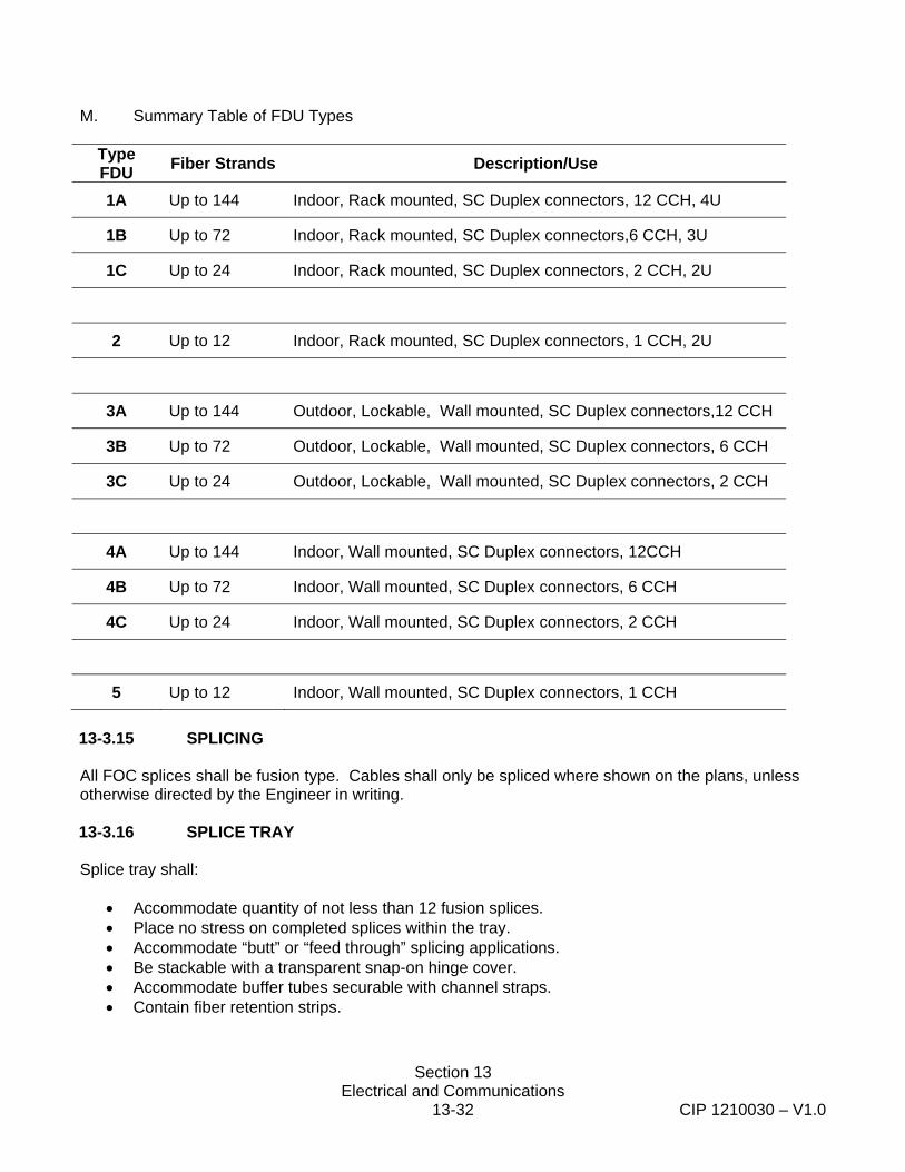
Section 13 Electrical and Communications
13-32 CIP 1210030 – V1.0
M. Summary Table of FDU Types
Type FDU Fiber Strands Description/Use
1A Up to 144 Indoor, Rack mounted, SC Duplex connectors, 12 CCH, 4U
1B Up to 72 Indoor, Rack mounted, SC Duplex connectors,6 CCH, 3U
1C Up to 24 Indoor, Rack mounted, SC Duplex connectors, 2 CCH, 2U
2 Up to 12 Indoor, Rack mounted, SC Duplex connectors, 1 CCH, 2U
3A Up to 144 Outdoor, Lockable, Wall mounted, SC Duplex connectors,12 CCH
3B Up to 72 Outdoor, Lockable, Wall mounted, SC Duplex connectors, 6 CCH
3C Up to 24 Outdoor, Lockable, Wall mounted, SC Duplex connectors, 2 CCH
4A Up to 144 Indoor, Wall mounted, SC Duplex connectors, 12CCH
4B Up to 72 Indoor, Wall mounted, SC Duplex connectors, 6 CCH
4C Up to 24 Indoor, Wall mounted, SC Duplex connectors, 2 CCH
5 Up to 12 Indoor, Wall mounted, SC Duplex connectors, 1 CCH
13-3.15 SPLICING All FOC splices shall be fusion type. Cables shall only be spliced where shown on the plans, unless otherwise directed by the Engineer in writing. 13-3.16 SPLICE TRAY Splice tray shall:
• Accommodate quantity of not less than 12 fusion splices. • Place no stress on completed splices within the tray. • Accommodate “butt” or “feed through” splicing applications. • Be stackable with a transparent snap-on hinge cover. • Accommodate buffer tubes securable with channel straps. • Contain fiber retention strips.
Section 13 Electrical and Communications
13-33 CIP 1210030 – V1.0
13-3.17 CATEGORY 6 PATCH PANEL
The category 6 (CAT6) patch panel shall have 48 Gigabit Ethernet ports; mount in a standard EIA-310-D, 19 inch rack; and have a rear facing 110 Insulation-Displacement Connectors (IDC) terminal punch block that shall be used to terminate the Outdoor Rated CAT6 cables at each station. The CAT6 Patch Panel shall be a Dynacom part no. DY-2013-48C6E, or an approved equivalent.
13-3.18 GIGABIT NETWORK SWITCH The gigabit (GB) Ethernet network switch shall mount in a standard EIA-310-D, 19 inch rack. The network switch will be furnished and installed by the Owner. The Contractor shall coordinate with owner for the scheduling, delivering, installation and testing with the Owner. 13-3.19 MEDIA CONVERTERS Media converters shall convert the 100 Base-T interfaces of the Station Ethernet Hub to 100Base-LX for transmission over single-mode fiber-optic cabling. The 100Base-LX interface will be provided through a SC-type connector. The 100Base-T interface will be provided through a RJ-45 connector. Media converters installed in the communications cabinet will be rack-mountable, and shall share a common power supply. The shelf shall include all media converter units required to connects all field devices shown on the plans (e.g., VMS signs, PCIDs, TVMs). The contractor shall fill all blank media converter slots (bays) with foamcore or an approved equivalent material that is sized to the same outer dimensions of a standard media converter. The minimum number of slots (bays) for media converters within a shelf shall be 16. Each media converter shall conform to the IEEE 802.3z Gigabit Ethernet standards. The media converters will auto-sense full and half-duplex transmission. The media converters will provide LEDs for indication of Link, Power, and data transmit/receive status. The media converter will comply with the 2 kilometer operating distance for the optical port, and the 100 meter distance for the 10Base-T port. All media converters located within the communications enclosure shall be an Etherwan16 Bay 19 inch Rack Mounted Media Converter System. The Etherwan16 Bay Rack Mounted Media Converter System (EMC1600-RPSA2, or approved equivalent) shall mount in a standard EIA-310-D, 19 inch rack. The 16 media converters located in the shelf (rack mounted media converter system) shall be Etherwan EX42011, or an approved equivalent. All media converter located within the network device (e.g. TVM, PCID, VMS) shall be a single mode fiber (with SC connector ports) to Ethernet media converter, Etherwan EX42011, or an approved equivalent. 13-3.20 BI-DIRECTIONAL TRAIN TO WAYSIDE COMMUNICATION SYSTEM A. GENERAL The TWC interrogator shall be H&K HCS-V or equivalent capable of bi-directional data transmission. Data rate shall meet a minimum of 100kBits per second. The TWC equipment shall be compatible with the existing LRV and wayside TWC system. The Contractor shall demonstrate by test that the new TWC equipment is compatible with the existing system. Wayside interrogators, transmits and receives a 100 KHz interrogation signal through a loop antenna installed between the rails. On receipt of the
Section 13 Electrical and Communications
13-34 CIP 1210030 – V1.0
interrogation signal, while the LRV antenna is over a loop, the vehicle-borne transponder responds with a low power signal encoded with a 19-bit message. On validation by the interrogator, the message is passed on to specific electronic application cards in the interrogator, transmits and receives information over the WAN via the Ethernet port and network switch. B. TWC LOOP ANTENNA AND LOOP CONVERTER The TWC loop antenna shall be constructed in a figure “8” pattern as shown on the Plans and specified in these Special Provisions. Each loop antenna shall be connected to a tuned filter/loop connector (TF/LC) adjacent to the loop as required, and via shielded twisted #12 AWG, 2 pair conductor to the loop interrogator, from the TF/LC. The TWC Loop Converter shall be the H&K HCS-V-LC (Part number 44 783 040) or approved equivalent, capable of providing communications required for TWC system operation. Each loop antenna shall consist of one turn of insulated, stranded, copper wire suitable for a 30- year life in direct burial wet and dry applications, with a conductor size minimum of #8 AWG. The wire shall meet the requirements of Article 310 of the National Electrical Code. Insulation shall be type RHW, RHH, USE, or XHHW with a thickness of 45 mils. C. INTERROGATORS Interrogators shall provide the functional information, as required. The interrogator units shall be H&K type HCS-V bi-directional units and shall be able to be mounted in the existing standard EIA-310-D, 19” rack. The interrogator shall have an overall width of 19,” approximately 8.5" deep, and occupy approximately 3U of rack space. The interrogator unit shall include serial communication cards with a standard RJ-45 Ethernet port for connection to the gigabit Ethernet network switch. The interrogator shall be mountable in a standard 19-inch relay rack containing a backplane, power supply, transmit/receive cards, loop scanner card, timing card, shift register/buffer card and an application backplane. It shall be powered by 120 volts ac, 60 Hz source. The interrogator card rack shall contain space for application cards, which plug into the backplane and receive power from the interrogator power supply. D. SERIAL OUTPUT/INPUT CARD The serial output/ input card shall take data input and output signals from the back-plane of the TWC interrogator unit, provide signal level shifting to RS-232 levels, and provide RS-232 data input and output signals to a DB-9 male connector. The serial output/input card shall output train, route, and loop identification information. The serial output/ input card shall fit in the interrogator’s card rack and transmit and receive data and control inputs through a connector that plugs into the back-plane of the interrogator unit. The serial output/ input card shall process transmit and receive data thru a MAX232 integrated circuit, or an approved equivalent, with a master/ slave configuration. The mating half of the connector shall be a standard DB-9 male connector. Pin 5 shall be connected to ground, Pin 2 shall be RXD, and Pin 3 shall be TXD, unless otherwise approved. Pin selections shall conform to industry standards.
Section 13 Electrical and Communications
13-35 CIP 1210030 – V1.0
The serial output card shall be a printed circuit board. The printed circuit board and all components connected to the board shall be industrial grade or better. The power-supply and ground for the serial output card shall be obtained from the back-plane of the interrogator. The serial output/ input card shall transmit the same information via the Ethernet port. E. COMPATIBILITY WITH EXISTING TWC SYSTEM The TWC equipment shall be compatible with the existing LRV and wayside TWC system and be fully bi-directional. The H&K model HCS-V meets this requirement. The Contractor shall demonstrate by test that the new TWC equipment is compatible with the existing system. Wayside interrogators, transmit a 100 KHz interrogation signal through a loop antenna installed between the rails. On receipt of the interrogation signal, while the LRV antenna is over a loop, the vehicle-borne transponder responds with a low power signal encoded with a 19-bit message. On validation by the interrogator, the message is passed on to specific electronic application cards in the interrogator, which energize selected output relays or other output means. Provide TWC equipment which is compatible with the existing car-carried and wayside TWC system. The Contractor shall demonstrate by test that the new TWC equipment is compatible with the existing system. The existing TWC system consists of the following major subsystems:
1. The existing SANDAG TWC system consists of VETAG equipment manufactured by VECOM and HCS-R devices manufactured by Hanning & Kahl.
Programmable decoder cards contain eight programmable outputs for control of desired functions. These decoder card outputs supply the relay output card which has eight relays, each containing one voltage free contact. Each output relay contact is rated at 1 ampere, at 50 volts DC, non-inductive. F. TEST EQUIPMENT The Contractor shall supply one set of the necessary test equipment required to adjust and troubleshoot the TWC system, per manufacturer’s recommendations. 13-3.21 TWC LOOP TERMINATIONS The TWC Loop Wires shall terminate to a minimum of 5 double row AREMA standard terminals per loop. TWC Loop Wire Connectors and terminations in the communications shall conform to the recommended practices contained in Part 14.1 of the AREMA Communications and Signaling Manual. Terminals shall be mounted to a ¾ inch thick piece of marine grade plywood and mounted to the existing plywood back board in the rear of the existing communications cabinet using a minimum of six screws. The plywood back board shall be 6 inches longer (3 inches above and 3 inches below) and 6 inches wider (3 inches to one side and 3 inches on the other side) than the length and width of the double row of AREMA standard terminals. 13-3.22 PROGRAMMABLE LOGIC CONTROLLER (PLC) SYSTEM The Programmable Logic Controller (PLC) system shall be a GE Fanuc PACSystem RX3i, or approved equivalent, consisting of the following:
Section 13 Electrical and Communications
13-36 CIP 1210030 – V1.0
A. Rack Mounted Baseplate, 12 slot, IC395CHS0312, B. Central Processing Unit, IC695CPE305, C. Network I/O Module, IC695ETM001, D. Analog I/O Module, IC694ALG221, E. Discrete Input Module, IC694MDL634, F. Discrete Output Module, IC694MDL930, G. Universal Power Supply, IC695PSA140, H. Five (5) Filler Module(s), IC694ACC310, I. Energy PAC, IC695ACC400, J. APC Dry Contact I/O Accessory, K. Magnetic Door Security Contacts, L. Interposing relays, M. Temperature Sensor, and N. 24VDC Power Supply, OMRON S8VM-03024CD.
The PLC system shall provide temperature, intrusion alarm and UPS system alarm information to the WAN via the network switch. The Contractor shall install the PLC system in the communications enclosure and interconnect the PLC system as shown in the plans. The PLC system shall include all necessary control software and programming to provide a fully functional system. The door security switch shall have a gap distance of 1.5” and be mounted at the top inside corner of each door of the Communications Enclosure. The Contractor shall furnish and install all necessary mounting brackets and hardware. 13-3.23 INTERNET PROTOCOL (IP) / ETHERNET TO AUDIO CONVERTER Each IP/ Ethernet to Audio Converter shall be DIN rail mounted Digital Acoustics IP7 Series STX 1 Watt Audio Amplifier with a DIN Rail to 19 inch rack adapter kit, a 120VAC to 12VDC transformer, and TalkMaster EE Software, or an approved complete equivalent system. The IP/ Ethernet to Audio Converter shall have: a) 10/100 Base-T Ethernet interface; b) 8 Watt Speaker output; c) Microphone input port; d) Audio Line In/Out (Nominal 1V p/p); External I/O; and Sensor Input. The DIN Rail to 19 inch rack adapter kit shall be a StarTech.com Adjustable Rack Mount DIN Rail Kit with Top Hat/ Mini/ G Rails (ADJDINKIT), or approved equivalent. The DIN rail “Top Hat” mounting shall conform to EN 50022, and DIN 46277-3 standards. The DIN Rail to 19 inch rack adapter kit shall mount into a standard 19 inch Electronic Industries Alliance EIA-310-D rack. 13-3.24 DUAL CHANNEL AUDIO AMPLIFIER The Dual Channel Audio Amplifier shall be a Crown CTs 600, or approved equivalent. The dual channel amplifier shall accept an audio output from two Digital Acoustics IP7 Series STX converter (one per channel) (one channel per platform) and amplify each channel independently to boost the sound to 350 Watt 70.7V outputs per channel. The audio output level of each channel shall be adjustable in 2dB increments (to a maximum of 32dB). The amplifier shall be designed to be mounted in a standard EIA-310-D, 19 inch rack. The back of the amplifier shall be mounted in accordance with the manufacturer’s recommendation and shall be supported in the back by additional support brackets. 13-3.25 PUBLIC ANNOUNCEMENT HORNS
Section 13 Electrical and Communications
13-37 CIP 1210030 – V1.0
The public announcement horns shown on the plans shall be pole mounted 70V, 30 Watt reentrant horn type horns. A pole with a single horn shall be Bogen Communications, Inc. SPT30A, or approved equivalent. A pair of horns facing opposite direction on a single pole shall be Bogen Communications, Inc. part no. BDT30A, or approved equivalent. The frequency response shall be from 225 Hz to 14 kHz. Maximum rated power output shall be 30 watts RMS continuous. Dispersion shall be 100º, each horn. Sound pressure level, measured four feet on axis with 30 watt input @ 1000 Hz, shall be at least 121 dB for each horn. The unit shall incorporate a weather-sealed switch, to allow matching the loudspeaker to a 70V constant-voltage line. Power handling capacity shall be adjustable at 70V to 30, 15, 7.5, 3.7 or 1.8 watts. The loudspeaker shall be of weatherproof all-metal construction, with driver enclosed within a waterproof housing. The loudspeaker shall include a self aligning, field replaceable diaphragm. Screw terminals shall be provided for connection to the audio line. A TC SPT1 cover shall be provided to protect the connectors and impedance selector switch. Horn shall incorporate connection for strain relief for the speaker cables. An all-purpose mounting bracket shall provide precise positioning in the vertical and horizontal planes with a single adjustment. The bracket shall include banding slots to permit the loudspeaker to be banded the pole with ½ inch ASTM Type 316 stainless steel banding, or an approved equivalent mounting method that firmly attaches the horn to the pole. . Bracket and loudspeaker shall be finished in textured enamel. The horn diameter shall not exceed 9-5/8" in diameter. 13-3.26 AUDIO CABLE TERMINATIONS
Audio cables shall not be supported from their terminations. Cables shall be supported from the rack via Panduit zip ties or other cable management and support method approved by the Engineer.
IP/ Ethernet Converter to Amplifier Cable (each channel) Soldered or crimped spade type lugs shall be used to connect each channel cable to the amplifier. The copper drain wire shall be connected to the amplifier ground via a soldered or crimped spade type lug. The cable shall be connected to the IP/ Ethernet converter audio output port via a 3.81 mm DIN housing properly sized to match the equal number of connection positions as provided on the converter. Amplifer to Speakers Cabling Soldered or crimped spade type lugs shall be used to connect each set of speakers to the amplifier. Soldered or crimped lugs shall be used to make the connection at each loudspeaker.
13-3.27 ELECTRICAL SERVICE A. ELECTRICAL SERVICE CABINET AND FOUNDATION
Electric service must comply with Sections 86-2.03, “Foundation,” and 86-2.11, “Service,” of the Standard Specifications and these special provisions. Station electrical service enclosures shall comply with SDG&E Service Standards & Guide requirements for “Commercial Meter Pedestals Service 0 to 200 AMPS,” and other applicable provisions, and generally conform to the details and requirements for a CALTRANS Type III-C
Section 13 Electrical and Communications
13-38 CIP 1210030 – V1.0
service enclosure in accordance with the Standard Specifications, these Special Provisions, and as shown on the plans. Electrical Service Equipment Enclosures shall be a NEMA 3R rated and equipped with lockable hasps for all access doors. The enclosure fabrication shall conform to the provisions in Section 86-3.04, “Cabinet Construction,” of the Standard Specifications with 14-guage minimum thickness Type 304 grade A or B stainless steel. Electrical service enclosures shall consist of a utility company section with a heavy duty meter socket, with test blocks, rated for 200 amp service, and utility landing lugs, and a customer section with a dead front, load center(s), and lighting controls as shown on the plans. Bus bars shall be 98 percent conductivity copper conforming to ASTM B187, and shall be braced for the available fault current; contact surfaces shall be silver-plated. The neutral bus shall have the same rating as the phase bus bars.” Bus bar connections to the branch circuit breakers shall be the distributed phase or phase-sequenced type. Single phase, three-wire panel board bussing shall be such that any two adjacent single pole breakers are connected to opposite polarities so that two-pole circuit breakers can be installed in any location. Furnish a plastic laminated printed circuit directory, reflecting the actual circuit position, designation, circuit breaker current rating and number of poles, for each circuit, and attach the circuit directory inside the customer section access door with a permanent fastener. Each service shall be provided with up to 2 main circuit breakers which shall disconnect ungrounded service entrance conductors. Where the "Main" circuit breaker consists of 2 circuit breakers as shown on the plans or required in the special provisions, each of the circuit breakers shall have a minimum interrupting capacity of 42,000 A, rms.
B. CIRCUIT BREAKERS
Circuit breakers shall conform to the provisions in Section 86-2.11, “Service,” of the Standard Specifications. Circuit breakers shall be molded case, quick-made quick-break bolt-on type, with thermal magnetic type overload trip, interchangeable unit rate 125 amperes and above meeting the requirements of NEMA AB 1. Circuit breakers shall have the ampere-rating and number of poles as indicated on the plans. Circuit breakers shall have the ampere-rating and number of poles as indicated on the plans. GFCI circuit breakers shall be used for station platforms duplex outlet circuits in conformance with the National Electrical Code (NEC) standard practices. Circuit breakers shall be manufactured by GE, ITE, Crouse/Hinds, Murray/Siemens, Cutler-Hammer, Square-D; or an approved equivalent. Circuit breakers shall be of suitable capacities and type to protect the various pieces of apparatus from the effects of short circuits, overloads, or other faults. All circuit breakers or fuses for the equipment and systems shall be in accordance with these Specifications. The circuit breakers and device fusing shall be the correct size and rating for circuit current
Section 13 Electrical and Communications
13-39 CIP 1210030 – V1.0
interruption and shall protect the electrical equipment and circuits from short-term and long-term overloads.
C. CONDUIT INSTALLATION
The Contractor shall be responsible for installing up to 200-feet of conduit on the utility side of the meter for electrical service. Should amount of conduit exceed the stated amount, extra length shall be paid by extra work per linear foot as shown in the electrical and communication systems cost break-down. Conduit shall be installed in accordance with the SDG&E service order and meet requirements of SDG&E Service Standards and Guide Manual. Trenching and backfill shall conform to Section 13-4.03 “Excavation and Backfilling” of these Special Provisions. Work to remove and replace or restore surfaces including asphalt concrete pavement and pavers shall conform to Section 13-4.04 “Removing and Replacing Improvements: of these Special Provisions. Full compensation for trenching, conduit, backfill and surface restoration shall be included in the lump sum price paid for installing Electrical and Communications Systems.
13-3.28 BONDING AND GROUNDING Bonding and grounding shall conform to the provisions in Section 86-2.10, “Bonding and Grounding,” of the Standard Specifications and these Special Provisions. The Contractor shall insure that new underground electric service enclosures are properly grounded in accordance with applicable codes and utility company requirements. 13-3.29 CAMERA POWER SUPPLIES The CCTV camera power supplies shall mount in a standard EIA-310-D, 19 inch rack, and shall be provided with the following features and ratings:
a) Power Input: 115 VAC, 60Hz, 3 A.
b) Power Output: Sixteen (16), 24VAC, Class 2 Rated (power limited).
c) Power Disconnect: Circuit Breaker.
d) Rack Height: 2U.
e) Approvals: UL 2044
The camera power supplies shall be a R2416ULCB manufactured by Altronix, or an approved equivalent. 13-3.30 UNINTERRUPTIBLE POWER SUPPLIES (UPS)
The uninterruptible power supply and additional battery pack units shall mount in a standard EIA-310-D, 19 inch rack, and shall be provided with the following features and ratings:
a) Power Capacity: 2700 Watts/3000VA.
b) Input Voltage: 120 VAC, single phase (nominal).
c) Output Voltage: 120 VAC, single phase (nominal).
d) Output Voltage Distortion: Less than 5% at full load.
Section 13 Electrical and Communications
13-40 CIP 1210030 – V1.0
e) Waveform Type: Sine wave.
f) Rack Height: 3U.
g) Environmental: 0-95% RH, 0-40°C, 0-3000 meters.
h) Thermal Dissipation: 375 BTU/hr.
i) Approvals: FCC Part 15 Class A, UL 1449, and UL 1778.
j) Warranty: Two years The uninterruptible power supply shall be a SUA3000R3XLNETPKG manufactured by APC, or an approved equivalent. The additional battery pack units shall be a SUA48RMXLBP3U manufactured by APC, or an approved equivalent. 13-3.31 COMMUNICATION CABINET (ENCLOSURE) The Contractor shall conform to all requirements specified in Section 13-2, “Engineering and Design Submittals,” of these Special Provisions. Unless otherwise specified, the communication cabinets shall conform to the following: Enclosure Construction Cabinet enclosures shall be a standard product, manufactured by APX Enclosures, Inc., or approved equivalent, and shall conform to the requirements specified in these Special Provisions. Enclosure shall be a rainproof cabinet and dustproof as shown on the plans. The enclosure top shall be slanted to the rear to prevent standing water. Environmental protection shall meet the requirements for NEMA 250 Type 4X enclosures in the NEMA Enclosure Standards. Two-bay communications cabinet enclosures shall be bay 72 inches in length, 72 inches tall, and 36 inches deep and three-bay communications cabinet enclosures shall be 108 inches in length, 72 inches tall, and 36 inches deep. Enclosures shall be manufactured of 14-gauge, Type 304 Grades A or B Stainless Steel Sheet in accordance with Section 86-3.04 A “Cabinet Construction” of the Standard Specifications, except as otherwise specified herein. If the Contractor would prefer to use an alternative equivalent AWS welding method to weld the communication cabinets, then the Contractor shall submit the equivalent welding method to the Engineer in writing for approval. In order to be considered to be an equivalent process the alternative AWS welding methods shall: a) conform to an American Welding Society (AWS) standard process, b) result in a quality weld, and c) shall result in a weld that will not rust. The Engineer shall be the sole judge as to the quality and suitability of the alternative welding method, and the Engineer’s decision shall be final. Exterior welds shall be ground smooth. Edges shall be filed to a radius of 0.03 inches minimum. All hardware, including locks and fasteners, shall be of AISI 316 stainless steel, designed for a coastal salt-fog environment. Door locks shall be able to be locked with a pad lock. Enclosures shall be designed and installed with brackets and bolt downs to a reinforced concrete slab and shall comply with the seismic requirements indicated in the STRUCTURAL DESIGN CRITERIA,

Section 13 Electrical and Communications
13-41 CIP 1210030 – V1.0
Drawing No. S-001 GENERAL STRUCTURAL NOTES. Submit seismic anchorage and bracing calculations sealed and signed by a professional engineer. Communication cabinet enclosures shall be insulated with an R value of 4. Enclosures shall have two or three equipment bays as indicated on the plans. Each bay shall have a 19 inch rack, with at least 33 useable rack units of space, and a marine grade, ½” minimum plywood back board, painted black. The racks shall be tapped with standard 12-24 EIA spacing. Two-bay enclosures shall be provided with two 2-post, swingout racks. Three-bay enclosures shall be provided with two 4-post, fixed racks in the two end bays, and one two 2-post, swingout rack in the center bay. Enclosures shall have fiber-optic cable entry and shall be supplied with standard cable storage brackets or a reel with a minimum radius of 15 times the FOC diameter for storage. Enclosure shall provide space on the back board for up to 200 feet of coiled Fiber Optic Cable for each run terminating in the enclosure. Enclosure Air Conditioning System Each communications cabinet enlosure shall be provided with a Heat Exchanger (Air Conditioning Unit) manufactured by McLean Cooling Technology Model T-53, or an approved equivalent, mounted on the side of the enclosure that conforms to the following: 1. Two-bay enclosures shall have a minimum capacity of 12,000 BTU per hour, and three-bay
enclosures shall have a minimum capacity of 19,000 BTU per hour.
2. Mount to enclosure shall have a rubber gasket to create leakproof seal between heat exchanger and enclosure.
3. Have a 304 Stainless Steel enclosure Underwriters Laboratories, UL 50, NEMA 4X or greater rating for outdoor environments.
4. Utilize CFC- Free Refrigerant
5. Suppress electromagnetic interference (EMI) and radio frequency interference (RFI).
6. Have electrical voltage and electromagetic wave length (in hertz) ratings that are compatable with and enable the unit to utilize power from the electrical service at each station without transformation thru other devices. The unit shall be rated for operation at 230V, single phase.
7. Be constructed of materials that protect against internal and external corrosion in salty, wet environments.
8. Temperature Control Thermostat enabling the maximum and minimum internal cabinet temperature to be set within the range of 50 to 99º F minimum. The range may be greater then the range specified. Thermostat must prevent over cooling and provide for energy efficient operation.
9. Utilize tamper resistant hardware. All exterior hardware shall be made of stainless steel. Enclosure Electrical System Each enclosure shall include an electrical distribution and surge protection system as shown on the plans and as specified in these Special Provisions. Cabinet wiring shall conform to the requirements of Section 86-3.04C, “Cabinet Wiring” of the Caltrans Standard Specifications, unless otherwise specified

Section 13 Electrical and Communications
13-42 CIP 1210030 – V1.0
herein. Equipment shall be labeled in conformance with 86-3.05A “Labels” of the Standard Specifications. Enclosures shall provide National Electrical Code (NFPA-70) – compliant AC power distribution system. Circuit Breakers and Panelboard Communications cabinet enclosure shall be provided with a circuit breaker panelboard, with components, features, and ratings as shown on the plans and shall confirm to the bus bar provisions specified in Section 13-3.37.A. Circuit breakers shall conform to the provisions for circuit breakers in Section 13-3.27.B. Surge Protective Device (SPD) Communications cabinet enclosure shall be provided with a Surge Protective Devices in accordance with this Special Provisions and as shown on the plans. Test each surge suppression system and provide test data to the Engineer and SANDAG in accordance with Section 13-5 “Testing” of this Special Provision. The SPD shall be rated for a Surge Current of 65KA, be sized for the existing nominal voltage and electrical source configuration at each station, have all protection modes (Line to Neutral or Line to Line, Line to Ground, Neutral to Ground) that are appropriate for the type of electrical configuration at each site, and have LED’s, Enhanced Electro- Magnetic Interference / Radio Frequency Interference, and alarm relay contacts (normally closed) to provide status and malfunction information. The SPD and all components in the suppression path (including all current diversion components) maximum continuous operating voltage shall be greater than 125% of the nominal system operating voltage to ensure the ability of the system to withstand temporary root-mean-square (RMS) over-voltage. The operating frequency range of the SPD shall be at least 47-63 Hz. The SPD shall be capable of protecting against and surviving at least 6000 10 kA surges per ANSI/IEEE C62.41-1991 Category C without failing or degrading the UL 1449 surge suppression ratings by more than 5%. All protection modes of the SPD shall be internally fused with I²T capability to allow the suppressor’s maximum rated transient current to pass through the SPD without fuse operation. If the rated I²T characteristic of the fusing is exceeded, then the fusing shall open in less than one millisecond and clear both high and low-impedance fault conditions. The fusing shall interrupt up to 200kA symmetrical fault current with 600VAC applied. The SPD’s over-current protection circuit shall be monitored and provide indication of suppression failure and operability. Conductor level fuses or circuit breakers internal or external to the SPD shall not be acceptable. The system performance ratings shall be in conformance with UL 1449 listing ratings for IEEE C62.41 Category B3 impulse waveforms of 6 kV 1.2 x 50 microseconds, 3 kA 8 x 20 microsecond wave shapes. The response time shall be 0.5 nanoseconds. The SPD’s shall provide a minimum of 50 dB noise attenuation for 50 ohm measurement method, 10 kHz to 500 MHz. The SPD shall be UL 1283 listed. The Surge Suppression Assemblies shall be provided with new communications enclosures, connected to the enclosures panelboard via a 30 Amp, 2 Pole circuit breaker. Surge Suppression Assemblies shall be Liebert AccuVar Transient Voltage Surge Protection Device (SPD), or an approved equivalent.
Section 13 Electrical and Communications
13-43 CIP 1210030 – V1.0
If the Contractor proposes to furnish equivalent equipment to that identified in these Special Provision, then the Contractor shall demonstrate that the equipment provides all of the same or greater functionality than the equipment specified. Proposed equivalent products shall comply with all of functional, operational, material, design submittal, and all other requirements identified in these Special Provisions and shown on the plans. The equipment shall be UL listed. Equipment within or powered from the communication enclosure shall be protected by SPD. The Contractor shall determine the Nominal System Operating Voltage and Electrical Source Configuration and provide an appropriate SPD. Duplex Receptacles Each enclosure shall contain a minimum of two receptacles per bay. Each receptacle shall be a duplex, 3-prong, NEMA Type 5-15R grounding type outlet and shall conform to the requirements in UL Standard 943. Light Fixture Each bay shall include door-activated fluorescent overhead lighting. Terminal Blocks Terminal Blocks shall be heavy duty and conform to the requirements of Section 86-3.05, E, “Terminal Blocks” of the Standard Specifications, unless otherwise specified herein. Bonding and Grounding The enclosures shall include a ground bar solidly grounded to earth as shown on the plans to tie all metal structures to a common earth ground with suitable conductors. All metal doors, panels and racks shall be bonded with grounding straps. No hinged or bolted connections will be considered a suitable path to ground. Bonding and grounding shall conform to the provisions in Section 86-2.10, “Bonding and Grounding,” of the Standard Specifications, the National Electrical Code, these special provisions, and as shown on the plans. The Contractor shall install a 10 feet long 5/8 inch diameter copper clad steel ground rod (grounding electrode) and bond to the enclosure ground bus with a bare # 6 wire. The ground bus shall be bonded with a # 6 wire to the enclosure. Environmental Parameters Communications cabinets with accessories and ancillary components must meet or exceed those parameters as specified in Section 13-1.06.” 13-3.32 PLATFORM LIGHTING Work under this section shall include platform lighting to be furnished and installed as shown on the plans and directed by the Engineer. Platform lighting shall include foundations, light standards, light fixtures (luminaires).
Section 13 Electrical and Communications
13-44 CIP 1210030 – V1.0
Light standards, steel pedestals, and posts for luminaries shall be as shown on the plans and conform to the provisions in Section 86-2.04, "Standards, Steel Pedestals and Posts," of the Standard Specifications and Section 10-13.10.A "Steel Structures" of these Special Provisions. Steel bolts not designated on the plans as high-strength (HS) or stainless steel shall be for general applications and shall conform to the requirements in ASTM Designation: A 307. Anchor bolts shall conform to the requirements in ASTM Designation: F 1554, Grade 36. High-strength (HS) anchor bolts shall conform to the requirements in ASTM Designation: F 1554, Grade 105. Handhole reinforcement rings for standards, steel pedestals, and posts shall be continuous around the handholes. Handhole covers shall be provided with stainless steel, tamperproof hardware. Foundations for light standards shall be concrete CIDH piles, size and length as shown on the plans or as directed by the Engineer. CIDH concrete piling shall conform to the provisions in Section 49-4, "Cast-In-Place Concrete Piles," of the Standard Specifications and Section 10-12.06 “Cast-in-Drilled-Hole Concrete Piles” of these Special Provisions. Light standards and fixtures (luminaires) shall be of the types shown on the plans. 13-3.33 PASSENGER SHELTER LIGHTING Work under this section shall include passenger shelter lighting systems to be furnished and installed at various trolley stations as shown on the plans and directed by the Engineer. Passenger Shelter systems shall include light fixtures as shown on the plans, power supply, cabling and necessary appurtenances to furnish and install lighting complete in place. 13-3.34 MEASUREMENT AND PAYMENT Full compensation for conforming to the requirements of Section 13-3, “Materials,” shall be paid in conformance with Section 13-6, “Measurement and Payment” of these Special Provisions. 13-4 CONSTRUCTION
13-4.01 GENERAL All Work shall be identified on the contractor’s schedule. The Contractor shall prepare a 3 week look ahead schedule that shall be submitted to the Engineer and discussed at a weekly meeting. The Contractor shall coordinate all work activities with SANDAG, Metropolitan Transit System (MTS), and the San Diego Trolley Inc. (SDTI). Contractor shall submit flagging requests with SDTI at least 48 hours in advance of all Work activities. The Contractor shall provide location and scheduling information so that access to facilities can be arranged and all necessary staff members are present to flag and inspect the installation. A SDTI staff member shall be present to flag the location any time work is performed within 15 feet of centerline of track. The contractor shall submit completely filled out flagging request forms to San Diego Trolley, Inc. (SDTI) at 1255 Imperial Avenue, Suite 900, San Diego, CA 92101-7490, a minimum of 48 hours in advance of the start of the of Work.
Section 13 Electrical and Communications
13-45 CIP 1210030 – V1.0
All contractor personel working on existing catenary poles near an energized system shall be qualified to work in close proximity to energized lines up to 750 volts and shall be trained in safety procedures as stipulated by the National Electric Safety Code (NESC) and California PUC General Order No. 95. All contractor personel working on existing catenary poles near an energized system shall be experienced with training and working-level familiarity with proper methods and procedures for safely working in close proximity to energized electric utility power lines. Electrical installations shall be performed by electricians trained in electrical safety and compliance with the National Electrical Code. All systems shall be complete and in operational condition as specified herein at the time of acceptance of the contract. All work on the system shall conform to the following requirements. The Contractor shall restore all surfaces and work areas to the conditions prior to start of work at each site, including but not limited to clean-up, repaving, patching, painting, retouching, seeding and landscaping, to the satisfaction of SANDAG and The Engineer as a requirement for payment. All installation work shall be performed in conformance with the recommended installation methods described in the submittals specified in Section 13-2.03, “Recommended Installation Methods Submittals” of these Special Provisions. Work Near an Energized System The existing traction power system is rated at 650 VDC nominal. SANDAG and MTS considers this system “High Voltage.” The Contractor shall perfom his work to comply with the “High Voltage” provisions of the California Adminstrative Code and these special provisions. The Contractor shall adapt his methods and equipment to this condition, and shall take due precautions against accidents and damage to MTS equipment or materials. Operation of Existing MTS Facitlities The operation of existing equipment that may become energized by operation of circuit breakers or other controls, shall be performed only by personnel of SDTI. The Contractor shall be responsible for safety of all Work that shall be performed after appropriate steps have been taken by SDTI to tag equipment. The Contractor shall make all arrangements with SANDAG and SDTI for powering down the system and for obtaining necessary training to Work on MTS’s system. 13-4.02 MAINTAINING EXISTING AND TEMPORARY ELECTRICAL SYSTEMS
Except as otherwise provided for elsewhere in these special provisions, all installation work shall conform to the requirements specified in Section 86-1.06, “Maintaining Existing and Temporary Electrical Systems” of the Standard Specifications, unless otherwise specified herein. All ticket vending machines, communications systems, railroad signaling system, and lighting circuits shall remain in operation throughout construction. The existing Railway Signaling shall be protected in place. Ticket vending machines and lighting circuits shall be temporarily relocated to serve temporary station platforms where shown on the plans and specified in these Special Provisions.
Section 13 Electrical and Communications
13-46 CIP 1210030 – V1.0
13-4.03 EXCAVATING AND BACKFILLING
All installation work shall conform to the requirements specified in Section 86-2.01, “Excavating and Backfilling” of the Standard Specifications, unless otherwise specified herein. The Contractor shall take care to prevent contamination of the ballast during trenching and filling operations. Should the ballast become contaminated due to work done in the installation of conduit, foundations, cable or other related work, the Contractor shall clean and replace the affected ballast, or remove the contaminated ballast and replace it with new clean ballast.
13-4.04 REMOVING AND REPLACING IMPROVEMENTS All installation work shall conform to the requirements specified in Section 86-2.02, “Removing and Replacing Improvements” of the Standard Specifications, unless otherwise specified herein. The outline of all areas of pavement to be removed shall be cut to a minimum depth of 0.17 feet with an abrasive typed saw specifically designed for this purpose. Cuts shall be neat and true with no shatter outside the removal area. All trenches thru paved areas shall be backfilled in accordance with the San Diego County Design Standards. The Contractor shall install pavement that matches the existing finish of the existing pavement. At locations where the existing pavement has pavers, the Contractor shall install replacement pavers that match the existing pavers. 13-4.05 CONDUIT General All installation work shall conform to the requirements specified in Section 86-2.05B, “Use,” and Section 86-2.05C, “Installation,” of the Standard Specifications, unless otherwise specified herein. The Contractor shall locate all underground obstructions and utilities. Install conduit as near as possible to the routing indicated. Following markout the Contractor shall schedule a site meeting with the Engineer or designated representative to layout the proposed equipment and conduit locations. The Contractor shall, with the approval of the Engineer or designated representative, shift the location of the conduit package, as needed, to avoid interferance with existing equipment and structures as needed. The Contractor shall install duct seal around wire, cable, and over empty conduits at all entry points to enclosures, pull boxes, and vaults. Make connections including intercepting existing conduit, punching into existing pull boxes or vaults, panels, and other equipment.
Section 13 Electrical and Communications
13-47 CIP 1210030 – V1.0
Subsurface Conduit Contractor shall have Underground Service Alert (USA) mark out all existing utilities and retain an underground facilities locating company to locate and markout the existing MTS facilities as described in Section 10-1.02 “Obstructions and Underground Facilities” of these Special Provisions. USA can be reached at 1-800-227-2600 or 811. All subsurface conduit shall be schedule 40 PVC conduit conforming to Section 13-3.08, “Conduit” of these special provisions and shall be installed a minimum of 18 inches below the finished surface in paved areas, 30 inches below the finished surface in unpaved areas, and 66 inches below top of rail at track crossings. Track crossing trenches shall be backfilled with slurry per Section 19-3.062, “Slurry Cement Backfill” of the Standard Specifications. Conduit shall be bored or jacked under the trackbed at the locations shown on the plans. If noted otherwise, conduits installed under the railway shall be constructed by open trench method under the following conditions and restrictions:
1) Tracks shall not be closed at any time, except with the approval of SDTI. To facilitate open trench ductbank construction while the track remains open, the impact on track is limited to removal of 1 tie for the condition of 115 lb rail on ties spaced at 22 inches on centers. Contractor shall confirm the track conditions, prior to beginning work, and notify the Engineer in writing, if conditions dictate a different track crossing ductbank installation method than indicated on the plans.
2) Contractor shall coordinate with SDTI for a slow order to be issued during the work window.
3) The slow order shall be limited to 48 hours. 4) Contractor shall prepare and submit a Construction Staging Plan, within the limitations of
the work window, for approval by SDTI and the Engineer. 5) Open trench shall be backfilled with slurry cement backfill when the work is complete..
All trenching for conduit installation shall conform to requirements specified in Section 13-4.04, “Removing and Replacing Improvements.” Track crossing trenches shall be backfilled with slurry as specified in Section 19-3.062, “Slurry Cement Backfill” of the Standard Specifications. Warning tape shall be installed be provided and placed in the trench over all new conduits. The warning tape shall be 100mm wide with bold printed black letters of approximately 19 mm on bright orange color backround , and contain the printed warning “Caution Fiber Optic Line Buried Below,” repeated at approximately 800 mm intervals. The printed warning shall be non-erasable and shall be rated to last with the tape for a minimum of 40 years. The construction of the warning tape shall be such that it will not delaminate when it is wet. It shall be resitant to insects, acid, alkaline and other corrosive elements in the soil. It shall have a minimum of 712 N tensile strength over 150 mm wide strip and shall have minium of 700 percent elongation before breakage. Use sweeps with a minium bend radius of 16 inches, whenever physically possible. Dig boring pits a minimum of ten feet from existing tracks, unless otherwise approved by the Engineer. Design and submit all shoring plans as needed to install conduit system.
Section 13 Electrical and Communications
13-48 CIP 1210030 – V1.0
After cables are pulled in all ducts shall be sealed with duct seal. All conduits shall be completely sealed to prevent intrusion of foreign objects and creatures. When any facilities are placed below grade, a detailed conduit, cable, and facilities plan shall be submitted to the Engineer for approval. Surface Mounted Conduit All conduit installed above finish grade shall be galvanized rigid steel (GRS) conduit conforming to section 13-3.08, “Conduit,” of these special provisions. Surface mounted GRS conduit shall be installed on surfaces where shown on the plans. All surface mounted conduits attached to wall faces shall be firmly attached to the wall with hot dipped galvanized steel framing channels and fasteners. The channels shall be securely anchored to the wall using stainless steel mechanical wedge anchor fasteners. The channel spacing shall conform to the manufacturers recommendation and shall not exceed 5 feet. All GRS conduit hung from I-beams shall be mounted to hot dipped galvanized steel framing channels with fasteners hung from the beams with firmly attached anchors and anchor rods. All attachments shall be made inconformance with local, state, and federal standards seismic Zone 4 building code standards and requirements. The anchoring system shall constrain the horizontal movement of the conduit during an earthquake. Construct with sufficient rigidity to hold all mounted equipment and material in permanent and neat alignment. Paint all field cuts or welding of supports with one coat of zinc-rich coating at 3 mils dry. 13-4.06 ROTOR OR CORE DRILL EXISTING CONCRETE Contractor shall rotor or core drill existing concrete where shown on the plans and in conformance with these special provisions. The holes shall be drilled by drilling method that will not shatter or damage the concrete adjacent to the holes. The drilled hole diameter shall not be smaller than the diameter of the largest conduit coupler and no larger than the conduit diameter plus 2 inches. The Contractor shall grout around the conduit following conduit installation in the hole. 13-4.07 TRAFFIC PULL BOXES All installation work shall conform to the requirements specified in Section 86-2.06B, “Cover Marking,” Section 86-2.06C, “Installation and Use,” and 86-2.07, “Traffic Pull Boxes,” of the Standard Specifications, unless otherwise specified in these Special Provisions. All Pull Boxes shall be traffic rated and conform to the requirements in Section 13-3.9, “Pull Boxes,” of these Special Provisions. The Contractor shall remove and dispose of the existing pull boxes where shown on the plans and replace them with new traffic rated pull boxes. All existing conduit shall be trimmed, as needed, to enable the existing cabling and new FOC to be placed in accorance with the minimum bending radius of the cables.
Section 13 Electrical and Communications
13-49 CIP 1210030 – V1.0
The Contractor shall backfill around the pull boxes with select backfill or sand slurry. All backfill shall be compacted in accordance with Section 13-4.03, “Excavation and Backfilling” of the Special Provisions. 13-4.08 MODIFICATION OF EXISTING ELECTRICAL SYSTEMS General The following requirements apply to all electrical work. The Contractor’s attention is directed to Subsection 86-1.06, “Maintaining Existing and Temporary Electrical Systems,” of the Standard Specifications. All modification of existing electrical circuits shall be constructed in accordance with the Contractor’s approved design submittal as described in Section 13-2.02, “Engineering Design Submittals,” of these Special Provisions, unless otherwise directed by the Engineer. The Contractor shall move existing loads and breakers within the panel as needed to balance out the loads connected to each line (phase) as shown on the Contractors design submittal. The Contractor shall furnish and install plastic laminated printed circuit directory, reflecting the actual circuit position, designation, circuit breaker current rating and number of poles, for each circuit, and attach the circuit directory inside the customer section access door. The Contractor shall label all existing and new circuit breakers with labels conforming to Section 86-3.05A, “Labels,” of the Standard Specifications. Labels shall provide a description of the circuits connected to the breakers. Station Modifications The Contractor shall install new conduit where shown on the plans, rearrange existing circuits, rearrange existing breakers, and install new breakers and wiring as needed to provide power to the existing communications enclosures and various station electrical systems and to balance the loads on each line. Electrical power to the existing trolley shelters, platform lighting, Ticket Vending Machines, and Closed Circuit Televison System shall be maintained throughout this construction unless the station is out of service. The Contractor shall provide a generator as needed to maintain electrical power to station facilities described above. Existing power to the trolley station lighting shall be maintained to the maximum extent possible during the modification of existing circuits. 13-4.09 ELECTRICAL WIRING AND CABLING All installation work shall conform to the requirements specified in Section 86-2.08, “Conductors,” Section 86-2.09, “Wiring,” and Section 86-3.04C, “Cabinet Wiring,” of the Standard Specifications, except as otherwise specified herein. All wiring and cabling shall be installed in conduit, except where overhead, or where cable is run inside the pole. The Contractor shall extend or replace conductors as needed to provide power to the new communication enclosure and FDFs.
Section 13 Electrical and Communications
13-50 CIP 1210030 – V1.0
Raceways shall be thoroughly cleaned prior to installation to verify that no obstructions exist. All conduits shall be mandrelled prior to start of wire pulling to remove all debris and clear obstructions. No kinks in wire and cable will be permitted and bends shall be larger in radius than the minimum recommended by the manufacturer and those specified in Section 13-3.11, “Wire and Cable Materials,” of these Special Provisions.
All below ground splices shall be made in a pull box and shall be made water tight. Underground Splices shall be avoided. 13-4.10 BONDING AND GROUNDING All installation work shall conform to the requirements specified in Section 86-2.10, “Bonding and Grounding,” of the Standard Specifications, except as otherwise specified herein. Electrical services shall be bonded to the grounding electrode system. The grounding electrode system shall obtain a resistance to earth as specified in Section 13-5. Install additional gound rods in test wells, spaced at 10 foot intervals until the specified resistance to earth is established. All below grade connections shall be connected with exothermic welds. Above ground connections may be made with compression connectors or exothermic welds. Traction power parrallel feeder cables shall be bonded to the rails with exothermic welds as shown on the plans. 13-4.11 FIBER OPTIC CABLES General Installation procedures shall be in conformance with the procedures specified by the cable manufacturer for the specific cable being installed. The Contractor shall submit the procedures to the engineer in writing a minimum or 30 days prior to the start of cable pulling. FOC installation personnel shall also be familiar with the methods and procedures of installing fiber optic cables specified in this contract. The Contractor shall strictly adhere to the FOC manufacturer’s qualification of installation personnel and installation proceedures. The Contractor shall trim all existing conduit in existing pull boxes, as needed, to enable the FOC to be installed without exceeding the minimum bending radius of the cable. Under no circumstances shall fiber-optic cables be bent over a radius less than the manufacturer's minimum bending radius. The Contractor shall take care in handling the fiber-optic cable and reels. The Contractor shall be held responsible for any and all damage to the fiber-optic cable and/or fiber-optic cable reels. If cable reels are damaged, they shall be repaired or replaced with a new reel of FOC prior to installation. When lifting reels, a spreader bar shall be used to prevent lifting cables from touching the reel flanges. Reels in storage shall be securely blocked up off the ground. Particular care shall be taken at all times to prevent the fiber-optic cable from being kinked, twisted, abraded or damaged in any manner. If the FOC is damaged in any way, then the Contractor shall notify the Engineer and inform the Engineer of the proposed remedial action plan to address the

Section 13 Electrical and Communications
13-51 CIP 1210030 – V1.0
situation. FOC cables shall only be spliced at locations shown on the plans, unless otherwise approved by the Engineer in writing. If the Contractor requests permission from the Engineer to install additional fusion splices, not shown on the plans and permission is granted by the Engineer, then the cost for furnishing, installing and testing, the additional fusion splices shall be at the Contractors expense. At locations where it is not practical to prevent the fiber-optic cable from coming in contact with the ground surface or other obstruction, suitable shielding boards shall be placed under the fiber-optic cable to protect it from damage. Mechanical aids may be used to install the FOC, provided that a tension measuring device is placed in tension to the end of the cable, and the allowable tension does not exceed the manufacturers recommended pulling tension. A calibrated break-away feature shall be employed to work in tandem with the tension measuring device and limit excessive tension by disengaging just before the maximum allowable cable tension is exceeded. Information submittal on the proposed FOC pulling and stringing methods to be used shall be submitted to the Engineer within 30 days following the Notice to Proceed and a minimum of 30 days prior to the start of cable installation. The submittal shall contain project title and number; identify if it is for aerial or underground cable installation; equipment description and specifications; manufacturer’s test data covering the performance of the equipment and cable stress in a typical installation using cable equivalent to cable to be installed on this project; and user/installer manual for the equipment and installation proceedures. Cable pulling shall not begin until all submittal reviews have been completed and all of the Engineers comments have been addressed in writing. The review process of the submittal shall follow the process described in Section 13-2.02, “Engineering Design Submittals,” of these Special Provisions. Following the completion of all reviews of the submittal and prior to the start of cable pulling, the Contractor shall conduct a training section with his staff and up to three SANDAG representatives on proper operating, pulling, and safety proceedures. The Contractor shall notify the Engineer a minium of 48 hrs in advance of such training. The Contractor shall utilize installation methods that will maintain the minimum loaded bending radius of the cable at all times. Under no circumstance shall the cable be bent to a tighter bending radius then is specified in the Section 13-3.11.I, “Fiber Optic Cable,” of these Special Provisions. The take-up reel shall be started and the cable pulled at a speed no more than 5 miles per hour. Once cable movement has started a constant pull speed shall be maintained. The brake at the payoff reel shall be engaged to maintain adequate back tension and to prevent the cable from running free. Loss of back tension during the pull may result in twisting and possible damage to the cable. At all times during the pull, the tensional operator shall monitor the tension meter to assure that the maximum pulling tension is not exceeded. The cable shall be continuously inspected as it leaves the reels. If any damage or deformity is found, stringing shall be stopped and corrective action shall be taken prior to continuing the pull. The Project Manager shall first approve any corrective action. FOC shall not be installed in traction power conduits and vaults that contain traction power cables.

Section 13 Electrical and Communications
13-52 CIP 1210030 – V1.0
Pull the cable to the locations indicated at each terminal facility. Install a storage coil of 200 feet of cable in every run of FOC at underground splice box or pull box shown on the plans, unless otherwise directed by the Engineer. Every FOC run shall have at least one 200 foot coil or one aerial storage unit without exception. 50 feet of FOC shall be coiled up either side of each patch panel in each communications enclosure and rack. When the pulling grip is removed, cut off a minimum of twenty feet past the end of the grip to assure no stressed cable is used. Fiber Optic Cables Pulled in Conduits and Raceways All wiring and cabling shall be installed in conduit, except where overhead, or where cable is run inside the pole. Raceways shall be thoroughly cleaned prior to installation to verify that no obstructions exist. All conduits shall be mandrelled prior to start of wire pulling to remove all debris and clear obstructions. No kinks in wire and cable will be permitted and bends shall be larger in radius than the minimum recommended by the manufacturer and those specified in Section 13-3.11, “Wire and Cable Materials,” of these Special Provisions. A pulling machine shall be used that will not exceed the tension and bending radius ratings of the cable and will not cause any damage to the cable. All cable pulling equipment shall prevent sudden changes in cable tension and shall maintain minimum benging radius of 20 inches or greater. A tracer wire shall be provided and pulled in along side each FOC installed below ground on the project. The wire shall be No. 8 stranded, minimum, copper conductor with Type TW, THW, RHW, or USE insulation. The wires shall be carefully placed so as not to be damaged. The tracer wire shall be continuous thru the entire length of each run from pull box to pullbox, enclosure, or pole. The 1.5 m of slack shall be extended into each pull box and fiber optic vault from each direction. Tracer wire may be spliced in the pull boxes. At the Contractor’s option, installation of cable into conduit, ducts or subducts may be performed using an “Air Blown Method.” The “Air Blown Method” shall be an installation method that uses a mechanical device combined with a high speed air flow or compressed air to place cables into conduits, ducts, or subducts. The “Air Blown Method” shall conform to the following:
The method shall install cable without exceeding the cable manufacturer’s tensile and compressive strength ratings. The mechanical device shall be used to provide a pushing force on the cable into the conduit. The cable installation equipment shall also have, at a minimum, the following features: 1. Controls to regulate the flow rate of compressed air entering the conduit, duct or
subduct, and any hydraulic pnematice pressure applied to the cable.
Section 13 Electrical and Communications
13-53 CIP 1210030 – V1.0
2. Safety shutoff valves to disable the system in the event of sudden changes in pnematic or hydraulic pressure.
Measuring device to determine the speed of the cable during installation and the length of the cable installed. Provide Kellem grips and other supporting devices as required to support the cable in all vertical runs.
Apply an approved cable pulling lubricant to the cable as it is pulled off the payoff reel to minimize friction.
The cable shall not be pulled through more than 180 degrees of total bends in a continuous run. Where the cable is to be pulled through a raceway containing more than 180 degrees of load change, the cable shall be installed through multiple pulls by setting up pull and payoff points at intermediate vaults, manholes, or pull boxes. If intermediate pulls are not possible, consult with Engineer before proceeding.
Contractor shall be responsible for pumping or removing any dirt, slurry, mud, or water from any vault, pull-box or manhole as required to properly installing the cable.
The Contractor shall take any and all necessary measures to assure that the minimum bend radius of the cable is not violated, and that maximum pulling tensions are not exceeded.
13-4.12 FUSION SPLICING Following execution of contract, additional detail will be provided identifing specific fibers to be spliced together. The contract drawings identify the number of fibers to be spliced and location of splices. All terminations of fiber optic cables to patch panels shall have pigtails that are fusion spliced. FOC splices shall be fusion type. Every splice shall be tested. The mean splice loss shall be obtained by measuring the loss through the splice in both directions and then averaging the resultant values. The test shall be conducted at 1550 nanometers using an OTDR in conformance with Section 13-5, “Testing,” of these Special Provisions. At locations where new FOCs are being spliced together, the mean splice loss shall not exceed 0.07 dB per splice. If the mean splice loss exceeds 0.07 dB, then the Contractor shall cut out the splice and resplice the cable until it passes. All costs associated with resplicing and retesting shall be included in the price paid for various other items of work and no separate payment will be allowed therefor. At least 48 hours prior to the start of work at each location containing existing FOC, the Contractor shall notify the Engineer in writing of the schedule of all work activities at each site. The schedule shall include the time and date the Contractor intends to start work at each of the sites. Within 10 minutes after arriving at each existing FOC site for the first time, the Contractor shall take photos of the existing cables,and any apparent damage to the existing cables. The Contractor shall submit quality copies of the photos on quality photo paper to the Engineer within 24 hrs after the photos are taken. It shall be assumed that the existing cables are in pristine condition if the Contractor fails to take and submit the photos within the time frames specified above. At locations where existing FOC cables are to be spliced, the Contractor shall properly clean, cut, and prepare the cable ends and fiber strands for splicing.

Section 13 Electrical and Communications
13-54 CIP 1210030 – V1.0
At locations where new FOC is to be spliced onto existing FOC, the mean splice loss shall be lower than 0.1 dB per splice, unless otherwise specified herein. If the mean splice loss is greater than 0.1 dB, then the Contractor shall resplice and retest. If after the third attempt at obtaining a splice with a mean splice loss less than 0.1dB the splice still does not pass, then the Contractor shall average the results of the three previous tests. If the mean splice loss of the splice is average or less than average and does not exceed 3dB, then the splice is acceptable. If not, then Contractor shall resplice and retest the loss until the result is average or less than average of all of the previous tests and does not exceed 3dB. If after a total of five attempts the mean splice loss continues to exceed 3 dB, then the Contractor shall contact the Engineer for direction. The Contractor is not responsible for any preexisting conditions in the existing cable prior to the the Contractor arriving at the site, however, the Contractor shall be held responisble for damage to existing cables resulting from the Contractor’s work activities or if the Engineer is of the opinion that the Contractor failed to properly perform work involving the existing cables that is covered under this contract ( i.e take photos of the existing cable and submitting them prior to start of work ). All costs associated with resplicing and retesting shall be included in the price paid for various other items of work and no separate payment will be allowed therefor. The field splices shall connect the fibers of the two FOC lengths together. These splices shall be placed in a splice tray and these splice tray(s) shall then be placed in the splice closure. Fibers of the same buffer tube, but not being spliced shall be placed in a splice tray along side spliced fibers. Buffer tubes that do not require enclosed fibers to be spliced shall not be disturbed and placed in the splice closure. The termination splices shall connect the FOC span ends with pigtails. The termination splices shall be placed in a splice tray and the splice tray(s) shall then be placed in the fiber distribution unit (FDU). The individual fibers shall be looped one full turn within the splice tray to avoid micro bending. A 50 mm minimum bend radius shall be maintained during installation and after final assembly in the optical fiber splice tray. Each bare fiber shall be individually restrained in a splice tray. The optical fibers in buffer tubes and the placement of the bare optical fiber in the splice tray shall be such that there is no discernible tensile force on the optical fiber. All splices shall be protected with a metal reinforced thermal shrink sleeve. All fiber optic cables shall be labeled in the splice tray. Pigtail ends shall also be labeled to identify the destination of the fiber. Contractor shall perform fusion splicing in clean environment. Personnel shall be trained, certified and have minimum of three years of experience. Spices are only allowed where shown on the plans, unless otherwise approved by the Engineer in writing. Furnish and install heat-shrink fusion splice sleeves to all splices. 13-4.13 SPLICE TRAY
The splice trays shall conform to the requirements identified in Section 13-3.16, “Splice Tray,” of these Special Provisions.
Section 13 Electrical and Communications
13-55 CIP 1210030 – V1.0
All splice trays and fiber cable splicing installation methods shall conform to the manufacturer’s recommended installation methods, unless otherwise specified herein or directed by the Engineer. The manufacturer’s recommended installation methods shall be submitted to the Engineer a minimum of 48 hours prior to the start of installation of any splice trays.
13-4.14 FIBER OPTIC TERMINATIONS General Fiber optic outside plant cables entering a cabinet, enclosure or building shall be routed as described in these special provisions and as shown on the plans. The cable shall continue within the conduit to the designated termination point for distribution “breakout.” Distribution Breakout Once the fiber optic cable arrives within the building, it shall be routed within conduit to the penetration into the existing IAD and Building A communications rooms as shown on the plans. A minimum of 6 m of cable shall be coiled in the communications room at a location to be identified by the Engineer and the Facilites Engineer or designated representative at the preconstruction site layout meeting to be arranged by the Contractor a minimum of 48 hours prior to starting work. Fiber Optic Cable Assemblies and Pigtails All fiber optic cable assemblies and pigtails shall conform to the requirements identified in Section 13-3, “Materials,” of these Special Provisions. Field terminations shall be limited to splicing of adjoining cable ends and/or cables to pigtails. All terminations shall conform to all performance and testing requirements specified in these Special Provisions. 13-4.15 REMOVING, REINSTALLING, AND SALVAGING EXISTING EQUIPMENT Where equipment is shown to be removed and salvaged on the plans, the Contractor shall remove and salvage the equipment in accordance with Section 86-7, unless otherwise specified herein. The contractor shall contact Fred Byle at (619) 559-4937 a minimum of 24 hours in advance of delivery of the salvaged materials to make necessary arrangements to deliver the materials. All salvaged materials shall be log on a bill of materials form that reflects the description of the materials and quantities. At time of delivery the Contractor shall obtain a signature from the MTS representative on the bill of materials. Materials shall be delivered to the MTS storage facility in downtown San Diego, CA. Reinstalling removed electrical equipment shall conform to the provisions in Section 86-7.02, “Reinstalling Removed Electrical Equipment," of the Standard Specifications and these Special Provisions. 13-4.16 CONDUCTORS AND CABLES Conductors and cables shall be run in conduit (or Panduit within cabinets), except where conductors and cables are run inside poles or in surface wireway or pull box. Electrical wires shall conform to
Section 13 Electrical and Communications
13-56 CIP 1210030 – V1.0
the provisions in Section 86-2.08, “Conductors," of the Standard Specifications and these Special Provisions. All AC power distribution cable shall be single conductor unless otherwise specified. 13-4.17 ELECTRICAL SERVICE CABINET The installation of the electrical service cabinet shall conform to all SDG&E Utility Service Guide Requirements, Sections 86-2.03, “Foundation,” and 86-2.11, “Service,” of the Standard Specifications, and these special provisions. 13-4.18 ELECTRICAL SERVICE CABINET WIRING All service cabinet wiring shall conform to Section 86-3.04C, “Cabinet Wiring,” of the Standard Specifications. 13-4.19 PUBLIC ADDRESS HORN INSTALLATIONS PA system horns shall be firmly attached to the pole or structure to which it is mounted. At all horn locations the speaker cable shall be supported by a mechanical means that prevents the cable from applying force to the point of termination of the cable. At each horn location the shield lead wire shall be firmly connected together to create a continuous continuity path back to the ground connection point on the amplifier unit. The shield lead wires shall be connected using crimped on lugs. 13-4.20 BI-DIRECTIONAL TRAIN TO WAYSIDE COMMUNICATIONS The Contractor shall furnish, install, wire, test and commission train-to-wayside communications systems (TWC) as shown on the Plans. The equipment shall be compatible with SANDAG’s present system for destination signal display. Car-carried TWC transponders are by others. A. TWC LOOP ANTENNA AND LOOP CONVERTER
Furnish and install TWC loop antenna and associated loop converter as shown on the plans. The loop shall be constructed in a figure 8 pattern, and compatible with a support structure affixed directly to the rails in open right-of-way, and beneath pavement in paved areas. The Contractor shall submit installation details of the loops and loop converter for approval by the Engineer. Pavement shall be sawcut to create straight, neat appearing lines. All sawcuts shall follow existing score lines or joints in the pavement wherever such exist, and shall run parallel to adjacent joints where no joints presently exist. All sawcuts shall be cleaned of debris and moisture before cable is installed, and prior to installation of sealant. All existing conduit raceways shall be used if possible.
B. INTERROGATORS
Provide interrogators as indicated on the Plans. The interrogators shall provide information that will be used by central control to control the platform signs, the interlocking equipment, and to a train tracking system via the contractor furnished network switch that will be connected to central control via the station network switch and WAN.
1. Interrogators shall be configured for operation with a loop card, which can serve up
to four loop antennas. Provide power supplies and slots for 9 application cards.
Section 13 Electrical and Communications
13-57 CIP 1210030 – V1.0
2. Provide programmable communication cards as specified and shown on the plans.
3. Install the interrogators and associated application cards in the existing 19-inch racks. Terminate the loop antenna cables to the backboard of the Communications cabinet as shown on the plans and run internal cabinet cables to the loop application card.
13-4.21 COMMUNICATIONS CABINETS General The Contractor shall furnish and install the new 3 Bay Communications Cabinet as shown on the plans. The Contractor shall: a) furnish and install local area network equipment in the 19 inch racks, b) wire and make all necessary connections at each station to build the LAN at each station, c) make all necessary connections between field devices (passenger card interface devices (PCID)s, Ticket Vending Machines (TVMs), Variable Message Signs (VMS), Traction Power Substations, and Signal Houses), d) coordinate, communicate, and schedule SANDAG’s network switch installation contractor to install the new SANDAG furnished network switch, and e) make all wide area and local area network connections to the new network switch as shown on the plans and specified in these special provisions. The communications system equipment shall be conform to TIA/EIA-568-A standards and shall consist of all equipment in the communications cabinet, WAN connections; station LAN electronics, connecting hardware, patch cords, horizontal cabling, and work area cables (cords). The Contractor shall be responsible for maintaining and transferring all terminations and connections to the wide-area network. All wiring shall be placed in new Panduit to be secured to the existing communications rack. The contractor is responsible for verifying that the wide area network is working properly during and after construction. Any terminations needed due to construction damage are at the cost of the contractor. Cabling and wiring within the communications cabinets shall be neatly arranged and laced, or enclosed in plastic tubing or raceway (Panduit or approved equal). Screwed in cable support assemblies shall be used to support cables from the backboard and internal metal members. The Contractor shall not install screws through the external sheet metal faces of the cabinet. Cables shall not be supported from points of connection or terminals. All cables shall have strain relief supports near the points of termination that support the weight of the cable. Strain relief support shall be located within 18 inches of the point of cable termination, except locations where the overall length of a CAT6 Patch Cord or Fiber Optic Patch Cord is less than 18 inches in length. Patch cords less than 18 inches in overall length may be supported by their points of connection (termination). Contractor shall protect in place the existing WAN fiber optic cable, except where it must be removed, reinstalled, and reconnected in order to perform the work shown on the plans. At each station the Contractor shall furnish and install new splice closures, 12 strand single mode fiber cable, Fiber Distribution Units, and splice fiber strands as shown on the plans and specified in these Special Provisions to create a wide area network (WAN) connection between the station local area network (LAN) and the central control facility LAN. Except where otherwise directed, the Contractor shall protect in place all existing electrical circuits. Power supplies for existing media converters and network switches shall be removed (unplugged from the duplex outlet or power strip) and salvaged along with the network device to which it supplies power. Cables shall be trained into final position while observing minimum bending radii. Slack shall be provided at all terminals in an amount sufficient for two re-terminations. Wire and cables where
Section 13 Electrical and Communications
13-58 CIP 1210030 – V1.0
connected directly to equipment shall be of sufficient length to allow access for removal and inspection of equipment. Wires and cables shall be continuous, without splices, between terminals within a housing and enclosure or piece of equipment. Termination work shall be conducted under clean and dry conditions. Connectors shall be fitted with retentive dust caps. Crimp style connectors shall be applied with a proper tool which prevents opening of the handles until the crimp is complete, unless the crimp connector manufacturer recommends the use of an alternative tool type. Manufacturer recommended alternative tooling shall be submitted to the Engineer prior to start of work on the termination of conductors. Conductors used in cabinet wiring shall be punched down to punch down terminal blocks with tooling conforming to the recommendations of the manufacturer. All other copper conductor terminations shall have soldered on lugs. Bare stranded wire shall not be terminated to terminal posts without a soldered on lug connector. For stranded copper wire, compression-type, insulated terminals in accordance with the wire and cable manufacturers' recommendations shall be used. The terminals shall be installed only with tools and techniques recommended by the terminal manufacturer. Wires and cables shall be terminated at terminal blocks as shown on the plans. Compression-type insulated terminal connections to terminal blocks shall use a single washer on top of the terminal. Wire eyes require two washers for one eye, three washers for two eyes. Connections shall be completed with double nuts torque to the rated value of the nut manufacturer. Following installation of the new 3 bay communications cabinet complete with network equipment and wiring at all stations within a Milestone segment, the Contractor shall make arrangements with SANDAG and it network switches installation vendor and arrange for installation of the network switch equipment. A minimum of 72 hours in advance of the desired installation date the Contractor shall contact Dale Neuzil of SANDAG at (619) 595-5373 and the Resident Engineer and arrange for installation of the network switches at all of the stations contained within the milestone segment.
13-5 TESTING General All material, equipment, devices, and installation testing shall be demonstrated to operate and conform to all requirements specified in Section 6-3, “Testing,” and all other sections of the Standard Specifications and these Special Provisions. The Contractor shall prepare test plans and proceedures for all tests identified in the Standard Specifications and Special Provisions. Test plans and proceedures shall be submitted to the Engineer a minimum of 30 days prior to start of testing. The Contractor shall address all comments raised durring the Engineers review of the documents. The Contractor shall provide all personnel, equipment, instrumentation, and materials necessary to perform all testing. The Engineer shall be notified two weeks prior to all field tests. The notificaiton shall include the exact location or portion of the system to be tested. The proceedures shall identify the tests to be performed and how the tests are to be conducted. Included in the test proceedures shall be the model, manufacturer, configuration, calibration, and alignment procedures for all proposed test equipment. Documentation of all test results shall be provided to the Engineer within 5 working days after the test is completed.
Section 13 Electrical and Communications
13-59 CIP 1210030 – V1.0
The Contractor shall supply a copy of all test data and reports to the Engineer and SANDAG for written approval at the completion of each test. All test equipment shall be calibrated within 30 calendar days prior to use, unless otherwise approved by the Engineer. Proof of calibration shall be submitted with all test reports. Contractor shall submit copies of certificates of calibration for the appropriate equipment (OTDRs, fusion splicing equipment, power meters, etc.) and certify that equipment components have been replaced at appropriate intervals. Note that rental equipment shall not be used without prior authorization from the Engineer. The Contractor shall have submitted testing procedures for the Engineer’s review and shall have received approval from the Engineer. No testing shall be performed unless the Contractor has the approved test procedures in hand. The Contractor shall schedule testing in consultation with Engineer. Contractor shall completely investigate any discrepancies, defects or anomalies, propose corrective action to the Engineer for approval, and take appropriate action to correct discrepancies, defects, and anomalies. Functional tests shall be performed to the satisfaction of the Engineer. All instruments or recorders employed in these test programs shall bear a record of calibration against certified standards by the National Institute of Standards and Technology. Such calibrations shall be made at least each 180 days and at such other periods as may be directed by the Engineer. Each test record shall identify the instrument employeed and the last date of calibration. Public Address testing shall be in accordence with ASTM E1014 - 08 Standard Guide for Measurement of Outdoor A-Weighted Sound Levels, and ensure appropritate NR (Noise Rating) Levels are in line with the EPA guidelines, taking into account ambient noise at each site. Electrical Testing Contractor shall perform all tests inconformance with the requirements specified in Section 86-2.14, “Testing,” of the Standard Specifications and these special provisions. The Contractor shall prepare test plans and perform tests on existing and new load centers and circuit breakers to properly size and furnish electrical systems in conformance with the requirements of the National Electric Code, Standard Specifications, these Special Provisions. Contractor shall test all electrical installations and submit a test report of the voltage measured at the outlet or point of connection to load. Contractor shall supply a list of all locations with the rating of the station main circuit breaker and the enclosure circuit breaker. Ground resistance tests of the grounding system shall be made and recorded. Test instruments shall be shall be capable of accurate resistance measurements and shall have a voltage rating of not less than 600V. Ground resistance values shall not exceed 5 ohms. Ground resistance tests shall be made in accordance with the methods as described in IEEE Standard 81, based on the three-probe test method, using a recently calibrated and suitable soils resistance test meter.
Section 13 Electrical and Communications
13-60 CIP 1210030 – V1.0
Ground Verification Testing The Contractor shall perform a ground verification test to verify that the ground at each grounding system location is less than 5 ohms. Public Address Verification Testing The Contractor shall broadcast an audible message over the public address sytem over each platform and adjust the volume to the satisfaction of the Engineer. The message shall be clear, without static, and clearly understood. Unshielded Twisted Pair Testing Link Test Configuration: Perform metered field tests on each four-pair UTP cable link through the wiring block, patch panel, and/or telecommunication outlet (T.O.) terminations at each end of the cable section using the basic link test configuration described in TIA/EIA 568-B.1. Channel Test Configuration: Perform metered field tests on each four-pair UTP cable channel, including all cabling sections, cross-connect equipment, jumper wire and/or patch cables, T.O., and work area station cords through the connectors at each end, but not including connections to active equipment using the channel test configuration described in TIA/EIA 568-B.1. Horizontal Performance Tests: Use field test instruments capable of the swept/stepped frequency voltage measurements in accordance with the performance parameters required by TIA/EIA 568-B1. Test each horizontal link or channel pair to verify wire map, length, attenuation, and near-end crosstalk (NEXT) as described in TIA/EIA 568-B.1. TIA/EIA 568-B.1 allows for a 10 percent uncertainty in the nominal velocity of propagation of signals in UTP cable when determining the cable length with an electronic tester. If during a test for data link, the tester identifies a length greater than 90 meters (295 feet), verify the cable’s physical length does not exceed 90 meters. Test Reports: Include field test results for each pair, including cable link length in accordance with TIA/EIA 568-B.1. The test summary will include: Cable identification as it appears in the contract documents, cable identification as it is labeled. And pass or fail status. Fiber Optic Testing General Testing shall include the tests on elements of the passive fiber optic components: (1) at the factory, (2) after delivery to the project site but prior to the installation, and (3) after installation. A minimum of 15 working days prior to arrival of the cable at the site, the Contractor shall provide detailed test proceedures for all field testing for the Engineer’s review and approval. Factory Testing Documentation of compliance with the fiber specifications as listed in the fiber characteristics table shall be supplied by the original fiber manufacturer. Before shipment, but while on the shipping reel, 100 percent of all fibers shall be tested with an OTDR for attenuation. Copies of the results shall be attached to the cable reel in a waterproof pouch and submitted to the Contractor and to the Engineer.
Section 13 Electrical and Communications
13-61 CIP 1210030 – V1.0
Arrival on Site The cable and reel shall be physically inspected on delivery and tested with an OTDR. Each reel shall be assigned a unique identifier which shall be included on the test reports. The installed cable shall be traceable to the reel, and thus the manufacturer’s data. Verify each reel holds a single, continuous length of cable. The attenuation shall be measured for 100 percent of the fibers. Test each fiber at 1,310 nm and 1,550 nm in one direction. The failure of any single fiber in the cable to comply with these special provisions is cause for rejection of the entire reel. Test results shall be recorded, dated, compared and filed with the manufacturer’s test results. Attenuation deviations from the shipping records of greater than 5 percent shall be brought to the attention of the Engineer. The cable shall not be installed until completion of this test sequence and the Engineer provides written approval. Copies of traces and test results shall be submitted to the Engineer. If the test results are unsatisfactory, the reel of fiber optic cable shall be considered unacceptable and all records corresponding to that reel of cable shall be marked accordingly. The unsatisfactory reels of cable shall be replaced with new reels of cable at the Contractor's expense. The new reels of cable shall then be tested to demonstrate acceptability. Copies of the test results shall be submitted to the Engineer. After Cable Installation After the fiber optic cable has been pulled terminated, 100 percent of all the fiber links shall be tested for attenuation end to end with a Power Meter and Light Source in accordance with EIA Optical Test Procedure 171. Single mode fibers shall be tested at 1310 nm and 1550 nm. These tests shall be conducted in both directions. Test results shall be recorded, compared and proven to be within the design link loss budgets, and filed with the other recordings of the same links. Test results shall be submitted to the Engineer. Fiber links and channels shall be tested with an OTDR in one direction. Launch cables utilized for testing shall be of sufficient length to allow testing of the entire installed fiber and shall be terminated using the same connector as the installed cables. Test results shall be recorded, dated, compared, and filed with the previous copies of these tests. Copies of traces and test results shall be submitted to the Engineer. If the OTDR test results are unsatisfactory, the F/O cable segment will be unacceptable. The unsatisfactory segment of cable shall be replaced with a new segment, without additional splices, at the Contractor's expense. The new segment of cable shall then be tested to demonstrate acceptability. Submit OTDR test results for each fiber span, including hardcopy OTDR traces showing the entire fiber length for each fiber. Test data shall also include total fiber length, total attenuation (decibels), average attenuation per unit length (decibels/kilometer), and maximum (peak) attenuation per unit length (decibels/kilometer). Copies of the test results shall be submitted to the Engineer. Splices At the conclusion of all splices at one location, and before they are enclosed and sealed, all splices shall be tested with the OTDR, in both directions. Splices in segments shall be tested at 1310 nm and at 1550 nm. Individual fusion splice losses shall not exceed 0.04 dB. Measurement results shall be recorded, dated, validated by the OTDR trace printout and filed with the records of the respective cable runs. Copies of traces and test results shall be submitted to the Engineer. If the OTDR test results are unsatisfactory, the splice shall be unacceptable. The unsatisfactory splice shall be replaced at the Contractor's expense. The new splice shall then be tested to demonstrate acceptability. Copies of the test results shall be submitted to the Engineer.
Section 13 Electrical and Communications
13-62 CIP 1210030 – V1.0
Fiber testing includes Optical Time Domain Reflectometry (OTDR) testing and Power Meter testing. These tests will be performed on individual links as well as each channel (hub to hub). Final system verification testing shall be preformed by an independent agent retained by the contractor. Distribution Interconnect Package Testing and Documentation All the components of the passive interconnect package (FDUs, pigtails, jumpers, couplers and splice trays as shown on the plans and in these special provisions) shall comprise a unit from a manufacturer who is regularly engaged in the production of the fiber optic components. In developing the distribution interconnect package, each SC termination (pigtail or jumper) shall be tested for insertion attenuation loss with the use of an optical power meter and light source. In addition, all single mode terminations shall be tested for return reflection loss. These values shall meet the loss requirements specified earlier and shall be recorded on a tag attached to the pigtail or jumper. Once assembly is complete, the manufacturer shall visually verify that all tagging, including loss values, is complete. Then as a final quality control measure, the manufacturer shall do an "end to end" optical power meter/light source test from pigtail end to jumper lead end to assure continuity and overall attenuation loss values. The final test results shall be recorded, along with previous individual component values, on a special form assigned to each FDU. The completed form shall be dated and signed by the Manufacturer's Quality Control supervisor. One copy of this form will be attached in a plastic envelope to the assembled FDU unit. Copies will be provided separately to the Contractor and to the Engineer, and shall be also be maintained on file by the manufacturer or supplier. System Verification at Completion Final system verification testing shall be preformed by an independent agent retained by the contractor.
For terminated fibers, jumpers shall be used at both ends under test to validate connector loss. OTDR Testing -- Once the passive cabling system has been installed and is ready for activation, 100 percent of the fiber links shall be tested with the OTDR for attenuation. Print out shall include at least link number, fiber color, buffer color and cable number. Test results shall be recorded, dated, compared and filed with previous tests on the cable. A hard copy printout and an electronic copy of the traces and test results along with a licensed copy of the associated software shall be submitted to the Engineer. If the OTDR test results are unsatisfactory the link shall be replaced at the Contractor's expense. The new link shall then be tested to demonstrate acceptability. Copies of the test results shall be submitted to the Engineer. The OTDR testing equipment shall be calibrated to detect anomalies of no less than 0.2 dB.
The OTDR testing equipment shall support generation of test reports on paper. All testing shall be performed in accordance with the fiber optic test procedures defined in EIA 455-59 and as follows:
Verify the fiber length given by the trace corresponds to the estimated fiber run length. Verify no significant anomaly/loss exists on the “test fiber” that adds loss to the fiber run.
Section 13 Electrical and Communications
13-63 CIP 1210030 – V1.0
The Contractor shall scrutinize and correct the traces (in the field) for obvious testing-related issues such as ghost reflectance and low launch levels. Single mode fibers shall be tested at 1310 nm, 1383 nm, and 1550 nm. OTDR test results for each fiber span, including hardcopy OTDR traces showing the entire fiber length for each fiber in both directions. Test data shall also include total fiber length, total attenuation (decibels), average attenuation per unit length (decibels/kilometer), and maximum (peak) attenuation per unit length (decibels/kilometer). Copies of the test results shall be submitted to the Engineer.
Design Link Budget – Design Link budget shall be calculated following the following example:
Given:
Fiber loss (including splices): 0.38 dB/km at 1310 nm Connector loss: 0.30 dB per connection
If testing a run that is 30 km long with one patch-through (via patch cords) in the span, an expected loss at 1310 nm would be:
Fiber loss = 30 km x 0.38 dB/km = 11.4 dB Connector loss = 4 connectors x 0.30 dB/connector = 1.2 dB (one connector on each end and two connectors at the patch-through)
Therefore, a total expected loss = 12.6 dB. If the loss obtained is higher than this, the Contractor should initiate troubleshooting measures. Rotational optimization of the connectors shall not be permitted. If the circuit loss exceeds the calculated circuit loss, the circuit is unsatisfactory and shall be examined to determine the problem. The Engineer shall be notified of the problem and what procedures the Contractor proposes to eliminate the problem.
Cable Verification Worksheet – The Cable Verification Worksheet shown in Appendix A shall be completed for 100 percent of all links in the fiber optic system, using the data gathered during cable verification. The completed worksheets shall be included as part of the system documentation. Test Failures -- If the link loss measured from the power meter and light source exceeds the calculated link loss, or the actual location of the fiber ends does not agree with the expected location of the fiber ends (as would occur with a broken fiber), the fiber optic link will not be accepted. The unsatisfactory segments of cable, or splices shall be replaced with a new segment of cable or splice at the Contractor's expense. The OTDR testing and power meter and light source testing shall be completed for the repaired link to determine acceptability. Copies of the test results shall be submitted to the Engineer. The removal and replacement of a segment of cable shall be interpreted as the removal and replacement of a single contiguous length of cable connecting two splices, two connectors or one splice and one connector. The removal of only the small section containing the failure and therefore introducing new unplanned splices, will not be allowed. Test Reports -- Test reports shall be prepared for all fiber optic strands and all links and submitted to the Engineer in a bound test report. Each OTDR trace shall be identified by fiber ID (tube and fiber color or number), end points by site name, and launch point identified on the plans.
A. The Contractor shall use the “Fiber Optic Cable on the Reel on Site Test Report” shown in
Appendix A to record the test results of each test of each strand of each cable following arrival to the work site and before installation.
Section 13 Electrical and Communications
13-64 CIP 1210030 – V1.0
B. The Contractor shall use the “Link Loss Budget Worksheet” shown in Appendix B to record the test results of each test of each fiber strand link after the link is complete in place from end to end. Additional documentation shall be attached and submitted as needed for complete test disclosure.
The Contractor shall completely fill out test report forms, review the results, take all necessary corrective action to comply with the contract requirements, retest as needed, and submit the completed forms to the Engineer. The resulting confirmation of compliance / non-compliance will be submitted to SANDAG. 13-6 MEASUREMENT AND PAYMENT The contract lump sum price paid for “Electrical and Communications System – (Station)” shall include full compensation for furnishing all labor, materials, tools, equipment, and incidentals and for doing all the work involved in Electrical and Communications System at each station, as shown on the plans as specified in the Standard Specifications and these special provisions, and as directed by the Engineer. Full compensation for all additional materials and labor, not shown on the plans or specified, which are necessary to complete the installation of the various electrical and communications system, shall be considered as included in the contract lump sum price paid for Electrical and Communications System per trolley station and no additional compensation will be allowed therefor. 13-7 COST BREAK-DOWN The Contractor shall submit to the Engineer, a cost break-down for each station location of the contract lump sum item for Electrical and Communication Systems. Cost break-down tables shall be submitted to the Engineer for approval after the contract has been awarded. Cost break-down tables will be approved, in writing, by the Engineer before any partial payment will be made for the applicable items of electrical and communication systems involved. Cost break-downs shall be completed and furnished in the format shown in the generic sample of the cost break-downs included in this section. Line item descriptions of work shown in the sample, and the item descriptions identified in Section 86-1.03 the Standard Specifications are the minimum, but not limited to, to be submitted. Additional line item descriptions of work may be designated by the Contractor. If the Contractor elects to designate additional line item descriptions of work, the quantity, value and amount for those line items shall be completed in the same manner as for other unit descriptions. The line items given in the sample are to show the approach of preparing the cost break-downs by the Contractor. The Contractor shall determine the quantities required to complete the work shown on the plans. The quantities and their values shall be included in the cost break-downs submitted to the Engineer for approval. The Contractor shall be responsible for the accuracy of the quantities and values used in the cost break-downs submitted for approval. The sum of the amounts for the line items of work listed in each cost break-down table for Electrical System and for Communications work shall be equal to the contract lump sum price bid for Electrical and Communication Systems by each Trolley Station, respectively. Overhead and profit shall be included in each individual line item of work listed in a cost break-down table.

Section 13 Electrical and Communications
13-65 CIP 1210030 – V1.0
No adjustment in compensation will be made in the contract lump sum price paid for Electrical and Communication Systems due to differences between the quantities shown in the cost break-downs furnished by the Contractor and the quantities required to complete the work as shown on the plans and as specified in these Special Provisions. Individual line item values in the approved cost break-down tables may be used to determine partial payments during the progress of the work and may be used as the basis for calculating an adjustment in compensation for the contract lump sum item of Electrical and Communication Systems due to changes in work ordered by the Engineer. When the total of ordered changes to line items of work increases or decreases the lump sum price bid for Electrical and Communication Systems by more than 25 percent, the adjustment in compensation will be determined in the same manner specified for increases and decreases in the total pay quantity of an item of work in Section 4-1.03B, "Increased or Decreased Quantities," of these Special Provisions.
SEE NEXT PAGE
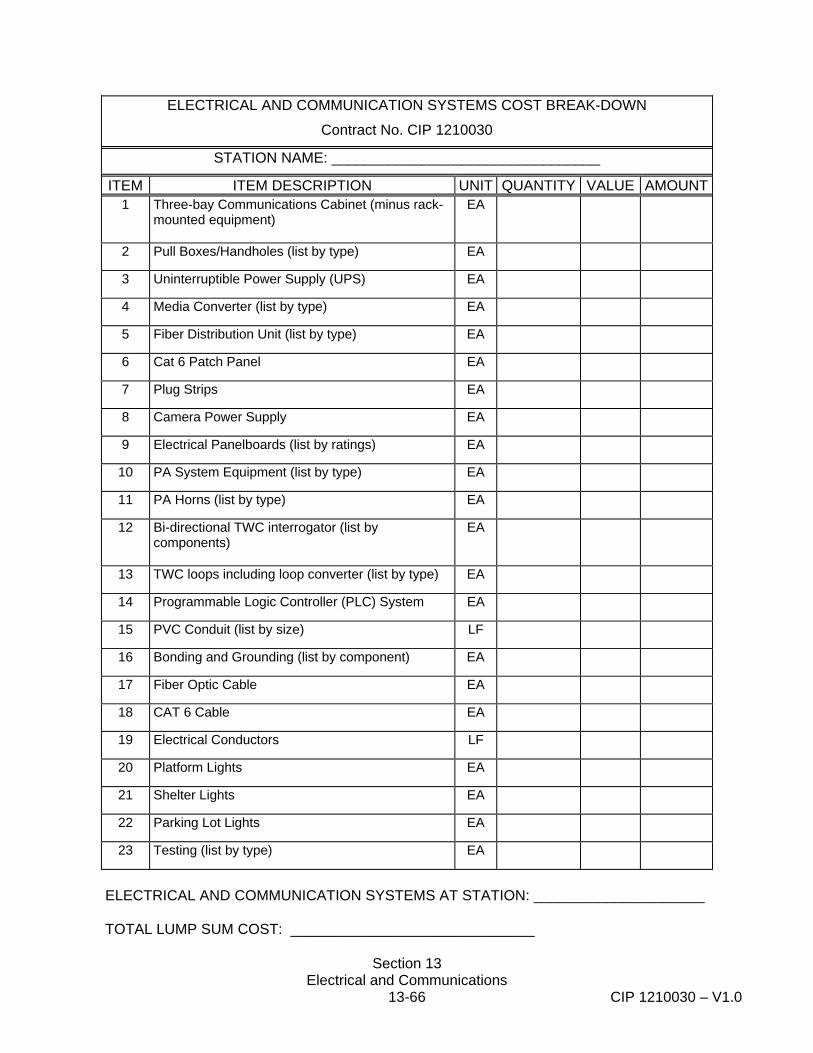
Section 13 Electrical and Communications
13-66 CIP 1210030 – V1.0
ELECTRICAL AND COMMUNICATION SYSTEMS COST BREAK-DOWN
Contract No. CIP 1210030
STATION NAME: _________________________________
ITEM ITEM DESCRIPTION UNIT QUANTITY VALUE AMOUNT1 Three-bay Communications Cabinet (minus rack-
mounted equipment)
EA
2 Pull Boxes/Handholes (list by type) EA
3 Uninterruptible Power Supply (UPS) EA
4 Media Converter (list by type) EA
5 Fiber Distribution Unit (list by type) EA
6 Cat 6 Patch Panel EA
7 Plug Strips EA
8 Camera Power Supply EA
9 Electrical Panelboards (list by ratings) EA
10 PA System Equipment (list by type) EA
11 PA Horns (list by type) EA
12 Bi-directional TWC interrogator (list by components)
EA
13 TWC loops including loop converter (list by type) EA
14 Programmable Logic Controller (PLC) System EA
15 PVC Conduit (list by size) LF
16 Bonding and Grounding (list by component) EA
17 Fiber Optic Cable EA
18 CAT 6 Cable EA
19 Electrical Conductors LF
20 Platform Lights EA
21 Shelter Lights EA
22 Parking Lot Lights EA
23 Testing (list by type) EA
ELECTRICAL AND COMMUNICATION SYSTEMS AT STATION: _____________________ TOTAL LUMP SUM COST: ______________________________
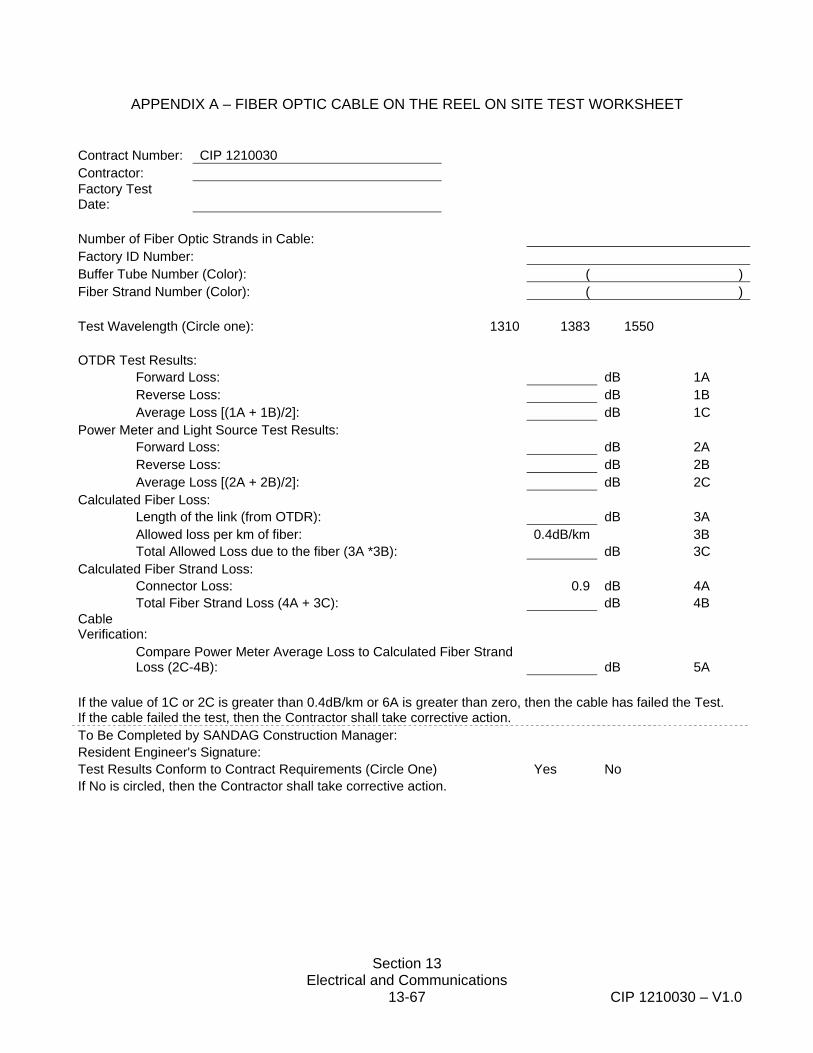
Section 13 Electrical and Communications
13-67 CIP 1210030 – V1.0
APPENDIX A – FIBER OPTIC CABLE ON THE REEL ON SITE TEST WORKSHEET
Contract Number: CIP 1210030 Contractor: Factory Test Date: Number of Fiber Optic Strands in Cable: Factory ID Number: Buffer Tube Number (Color): ( ) Fiber Strand Number (Color): ( ) Test Wavelength (Circle one): 1310 1383 1550 OTDR Test Results: Forward Loss: dB 1A Reverse Loss: dB 1B Average Loss [(1A + 1B)/2]: dB 1C Power Meter and Light Source Test Results: Forward Loss: dB 2A Reverse Loss: dB 2B Average Loss [(2A + 2B)/2]: dB 2C Calculated Fiber Loss: Length of the link (from OTDR): dB 3A Allowed loss per km of fiber: 0.4dB/km 3B Total Allowed Loss due to the fiber (3A *3B): dB 3C Calculated Fiber Strand Loss: Connector Loss: 0.9 dB 4A Total Fiber Strand Loss (4A + 3C): dB 4B Cable Verification:
Compare Power Meter Average Loss to Calculated Fiber Strand Loss (2C-4B): dB 5A
If the value of 1C or 2C is greater than 0.4dB/km or 6A is greater than zero, then the cable has failed the Test. If the cable failed the test, then the Contractor shall take corrective action. To Be Completed by SANDAG Construction Manager: Resident Engineer's Signature: Test Results Conform to Contract Requirements (Circle One) Yes No If No is circled, then the Contractor shall take corrective action.
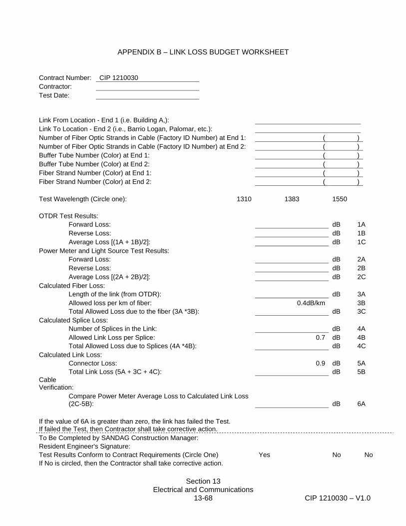
Section 13 Electrical and Communications
13-68 CIP 1210030 – V1.0
APPENDIX B – LINK LOSS BUDGET WORKSHEET Contract Number: CIP 1210030 Contractor: Test Date:
Link From Location - End 1 (i.e. Building A,): Link To Location - End 2 (i.e., Barrio Logan, Palomar, etc.): Number of Fiber Optic Strands in Cable (Factory ID Number) at End 1: ( ) Number of Fiber Optic Strands in Cable (Factory ID Number) at End 2: ( ) Buffer Tube Number (Color) at End 1: ( ) Buffer Tube Number (Color) at End 2: ( ) Fiber Strand Number (Color) at End 1: ( ) Fiber Strand Number (Color) at End 2: ( ) Test Wavelength (Circle one): 1310 1383 1550 OTDR Test Results: Forward Loss: dB 1A Reverse Loss: dB 1B Average Loss [(1A + 1B)/2]: dB 1C Power Meter and Light Source Test Results: Forward Loss: dB 2A Reverse Loss: dB 2B Average Loss [(2A + 2B)/2]: dB 2C Calculated Fiber Loss: Length of the link (from OTDR): dB 3A Allowed loss per km of fiber: 0.4dB/km 3B Total Allowed Loss due to the fiber (3A *3B): dB 3C Calculated Splice Loss: Number of Splices in the Link: dB 4A Allowed Link Loss per Splice: 0.7 dB 4B Total Allowed Loss due to Splices (4A *4B): dB 4C Calculated Link Loss: Connector Loss: 0.9 dB 5A Total Link Loss (5A + 3C + 4C): dB 5B Cable Verification:
Compare Power Meter Average Loss to Calculated Link Loss (2C-5B): dB 6A
If the value of 6A is greater than zero, the link has failed the Test. If failed the Test, then Contractor shall take corrective action. To Be Completed by SANDAG Construction Manager: Resident Engineer's Signature: Test Results Conform to Contract Requirements (Circle One) Yes No No If No is circled, then the Contractor shall take corrective action.

Section 13 Electrical and Communications
13-69 CIP 1210030 – V1.0
END OF SECTION 13
LTorio 1210030_5001933_SCT_13_Electrical_Comm.SCHMI 8/27/12

Section 14 Not Used
14-1 CIP 1210030
SECTION 14 NOT USED

Section 15 Block Signaling and Highway Crossing Warning 15-1 CIP 1210030
SECTION 15 BLOCK SIGNALING AND HIGHWAY CROSSING WARNING
15-1.01 DESCRIPTION OF WORK The Work specified in this section consists of general procedures and requirements necessary and incidental to the planning, installation, removal, relocation, modification, testing, placing in service, and documenting as-built conditions of the various signaling and highway-rail grade crossing systems to be protected by the Contractor. The Work shall consist of, but is not limited to: 1. The Contractor shall provide all materials and installation services required for complete working
systems, as described herein, and as shown on the Contract Drawings. 2. Contract Drawings represent a schematic representation of systems, components, and
materials that must be protected, re-installed, and/or relocated in conjunction with the Contractor’s rail and station improvements.
3. Contractor shall ensure all systems disturbed and/or modified are compliant with applicable rules
and regulations of CFR 49, Parts 234 and 236 and applicable CPUC General Orders 4. The Contractor shall be represented at all meetings held with the Engineer by a Systems Engineer
qualified in the design and application of the systems and equipment that must be modified and tested on this project.
5. No circuit or system is considered to have met the requirement of this Specification for function and
safety until it has been properly tested and verified in the field. Any circuit modifications made to meet the functional and safety requirements of this Specification shall be considered as a part of the Contractor's responsibility and therefore no additional compensation will be paid for this work.
6. The Contractor shall be responsible for providing continuous train control and highway-rail grade
crossing warning during all phases of construction. At no time shall the work of the Contractor cause delay to train operation, cause an unsafe condition to exist, or reduce the effectiveness or quality of the existing crossing warning systems. The Contractor shall submit, for approval by the Engineer, its proposed plan for providing alternate methods of crossing warning whenever an existing automatic crossing warning device is deactivated, altered, or modified in order to accommodate construction work. Alternate methods shall conform to CFR 49, Part 234, and all local ordinances.
7. Contractor shall provide rail bonding as required to ensure proper operation of the signaling and
traction power systems. The Contractor shall provide rail bonding, as necessary, to maintain existing systems during construction.
8. Contractor shall protect existing SDTI conduit and cabling and, where necessary, relocate existing
conduit and cabling in order to prevent damage to the cabling during all phases of work. 9. Contractor shall install, adjust, and test hand-throw switch and derail equipped with electric locks
Section 15 Block Signaling and Highway Crossing Warning 15-2 CIP 1210030
as shown in the contract drawings. Works shall include, but not limited to installation of conduit, underground cabling, aerial cabling, catenary pole mounted equipment enclosure, and associated hardware. The Contractor shall provide temporary switch point and fouling protection/detection at the time a switch point is installed. Contractor shall submit detailed circuit drawings depicting the proposed method of switch point and fouling protection/detection for approval of the Engineer. No work shall begin until the Contractor submittal has been approved by the Engineer.
10. The Contractor shall test and make operational the interlocking, block signaling, and highway
crossing warning systems that may be disturbed in the course of the Contractor’s work. The interlocking and block signal system may include track circuits, wayside color light signals, train-to-wayside communication (TWC) equipment, equipment enclosures and subsystems. The highway crossing warning system shall include the following: warning devices, AFO track circuits, wayside cabling, equipment enclosures, and associated materials, equipment appurtenances, and subsystems. The Contractor shall relocate components for the above systems and shall complete all work necessary to provide satisfactory performance of a complete, safe, and operable block signaling and highway crossing warning system.
11. The Contractor shall be responsible for the modifications, equipment, material, cables,
equipment and labor to provide a complete signaling and highway grade crossing warning system as shown on the Contract Drawings and documents. Contractor shall be responsible for the detailed design of temporary interfaces required to support full operation of existing systems until such time the final systems are placed in full and final operation.
12. The Contractor shall be responsible for relocation, removal, and salvage of existing signal
equipment and associated accessories. At no time will the Contractor be allowed to take the existing block signaling or highway grade crossing warning system out of service without prior approval from the Engineer.
13. The Contractor shall furnish, install, and test all items, including cables and interfaces necessary
to insure proper operation of the block signaling and highway grade crossing warning systems. 14. Contractor shall perform and document all tests and inspections in accordance with CFR 49
regulations, the AREMA Signal Manual, and these Specifications. 15. Contractor shall record the final as-built conditions of the signal and communication systems for
each location. 16. The TWC loops covered by this section provide routing requests and support nearside crossing
functions. Refer to Section 13-3.20 “Bi-Directional Train to Wayside Communication System” for the Contractor’s work in conjunction with TWC loops in support of station facilities.
17. Contractor’s work shall include, but are not limited to the items listed below in conjunction with the
Trolley Station Improvements. The disconnecting and rebonding of connections and relocation of apparatus shall be completed as many times as required to support the phasing of construction without additional cost to SANDAG.
a. Disconnecting and rebonding track wires. b. Disconnecting and rebonding impedence bond connections to rail and negative return.
Section 15 Block Signaling and Highway Crossing Warning 15-3 CIP 1210030
c. Relocation of impedence bonds from between the rails to the field side of the track as
depicted in Contract Drawing No. SG-5 and SG-6. At station locations, where the relocation to the field side will be in the passenger platform or in conflict with other appurtances, the impedance bonds shall be relocated to between the tracks. Work includes extending conduit and replacement of negative return cable as required.
d. Removal and installation of TWC loop and supporting frame. e. Installation of electric locks, AFO track circuit, associated controls and appurtenances for
hand throw switch 71A and derail 71B as depicted in the plans and these specifications. f. Protecting in place instrument enclosures, conduit, cabling, track wires, pull boxes, switch
mechanisms, signals, route selectors, crossing warning devices, TWC loops, and other signal apparatus within the limits of the right-of-way and of the work.
g. The adjustment and testing of all apparatus disturbed or replaced. h. Installation and testing of insulated joints as required in Section 12: Trackwork and these
specifications.
18. Contractor’s work shall include, but are not limited to the items listed below in conjunction with the Rail Replacement portion of the project. The disconnecting and rebonding of connections and relocation of apparatus shall be completed as many times as required to support the phasing of construction without additional cost to SANDAG.
a. Disconnecting and rebonding track wires and switch fouling. b. Disconnecting and rebonding impedence bond connections to rail and negative return
connection. c. Relocation of impedence bonds from between the rails to a location on the field side of the
track as depicted in Drawing No. SG-5 and SG-6. Work includes extending conduit and replacement of negative return cable as required.
d. Protecting TWC loops and supporting frame. e. Installation of new rods and associated hardware in conjunction with hand-throw switch rail
replacement. f. Protecting in place instrument enclosures, l conduit, cabling, track wires, pull boxes, switch
mechanisms, signals, route selectors, crossing warning devices, TWC loops, and other signal apparatus within the limits of the right-of-way and of the work limits.
g. The adjustment and testing of all apparatus that is disturbed or replaced. h. Installation and testing of insulated joints as required in Section 12: TRACKWORK and these
specifications.
Section 15 Block Signaling and Highway Crossing Warning 15-4 CIP 1210030
15-1.02 REGULATIONS AND CODES In addition to the Regulations and Code requirements specified in this section, materials and equipment for the block signaling system and the highway crossing warning shall conform to the latest recommendations of the AREMA Communications & Signals Manual and applicable SANDAG standard circuit plans. The compatibility shall include form, fit and function of block signaling and highway crossing warning systems. Existing circuits, equipment and material shall serve as the basis of design for signal design circuits, equipment and material. 15-1.02(a) The following General Orders (G.O.) of the State of California Public Utilities Commission (CPUC) shall apply: 1. G.O. 26-D: Clearances on Railroads and Street Railroads as to Side and Overhead
Structures, Parallel Tracks, and Crossings 2. G.O. 52: Construction and Operation of Power and Communication Lines for the
Prevention or Mitigation of Inductive Interference 3. G.O. 75-D: Regulations Governing Standards for Warning Devices for At-Grade Highway-Rail
Crossings 4. G.O. 88B: Alteration of Existing Grade Crossing of Public Roads, Highways, and Streets with
Railroads 5. G.O. 95 Rules for Overhead Electrical Construction 6. G.O. 118: Construction, Reconstruction, and Maintenance of Walkways and Control of
Vegetation 7. G.O. 128: Construction of Underground Electric Supply and Communication Systems 8. G.O. 143-B Safety Rules and Regulations Governing Light-Rail Transit 9. G.O. 164-D Rules and Regulations Governing State Safety Oversight of Rail Fixed Guideway
Systems 15-1.02 (b) The following parts of the Code of Federal Regulations, Title 49, Transportation shall apply: 1. Part 212: State Safety Participation Regulations 2. Part 214: Railroad Workplace Safety 3. Part 219: Control of Alcohol and Drug Use 4. Part 218: Railroad Operating Practices 5. Part 228: Hours of Service of Railroad Employees 6. Part 234: Grade Crossing Signal System Safety
Section 15 Block Signaling and Highway Crossing Warning 15-5 CIP 1210030
7. Part 236 Train Control Systems The Contractor shall be responsible for adherence to all of the above rules and reporting requirements, including those regulations which require pre-employment drug testing, random drug testing, and reporting and tracking hours of service of employees engaged in the installation and testing of signal facilities, and the reporting and tracking of employees injured in the performance of work on a railroad. Manual on Uniform Traffic Control Devices – California Supplement, Part VIII, Traffic Controls for Highway-Rail Grade Crossings, shall apply. 15-1.03 SYSTEMS PERSONNEL QUALIFICATIONS 1. Key employees of the Contractor engaged in the adjustment and testing of the various systems
shall be qualified and have had experience on an operating transit system in the type and level of systems installation and testing work as required herein. At a minimum “key employees” shall include the Contractor’s Systems Engineer, Construction Foreman, and Lead Wireperson. Additional experienced personnel shall be provided by the contractor for testing and placing systems in operation. Contractor shall submit resumes for the “key employees” to the Engineer. The Engineer's decision concerning the candidate's qualifications shall be final. Contractor shall propose alternate personnel if the original candidate(s) is found to be unacceptable. No signaling related work shall begin prior to the Contractor's “key employees” having been accepted by the Engineer.
2. The Contractor’s systems construction forces shall work under the supervision and direction of an
approved Systems Engineer. The Contractor’s Systems Engineer shall oversee the installation, adjustment and testing of signal related work. The Contractor's Systems Engineer shall be within the project limits whenever systems related work or whenever roadway or track construction work is in progress in the vicinity of existing wayside signaling equipment, highway-rail grade crossings, and/or cabling.
3. The Contractor’s Systems Engineer shall direct and certify the successful completion of all tests on
equipment and systems prior to releasing the systems for operation. The Contractor's Systems Engineer is responsible to ensure that all applicable test documentation is completed prior to, or immediately after, in-service testing is completed.
4. The Contractor's proposed Railroad Systems Engineer shall demonstrate experience in the
philosophy, application, and testing requirements of the various systems, including vital railroad signal systems. The Contractor’s proposed Systems Engineer shall have a minimum of 10 years systems supervisory or management experience on a major transit or commuter system in the United States. The proposed Systems Engineer shall also demonstrate knowledge of the governing CPUC and FRA rules and regulations. This demonstration shall be by interview of the proposed Systems Engineer by the Engineer prior to commencement of any systems related work. The Engineer's decision concerning the candidate's qualifications shall be final. The Contractor shall propose alternate personnel if the original candidate is found to be unacceptable. No signaling related work shall begin prior to the Contractor's Systems Engineer having been approved by the Engineer.
5. All Contractor field personnel must receive safety training that shall include a thorough briefing in
the rules of conduct in work areas where moving trains may be present. No work shall be performed on operating systems or appliances without a SDTI representative being present.
Section 15 Block Signaling and Highway Crossing Warning 15-6 CIP 1210030
6. Any Contractor personnel found to be acting in violation of safety or operating rules and regulations
will be barred from the work site. 7. 49 CFR Part 228 Compliance
a. Prior to any signal installation work being performed the Contractor shall submit a list of
employees that have successfully completed the pre-employment testing requirements and are in the random testing pool as outlined in the Contractor’s FRA accepted Control of Drug and Alcohol Use policy. Individuals providing “covered service,” as defined in Part 228, are subject to the Hours Of Service (HOS) restrictions specified in Part 228 and the pre-employment and random drug testing requirements in Part 219. The contractor’s, and/or subcontractor’s, employees that install, repair or maintain railroad signal systems provide “covered service.” For this contract “installing signal systems” shall include any work involving the placement or testing of a device, apparatus, or associated component utilized specifically in support of the railroad signal and highway grade crossing warning systems or subsystems. Examples of such devices, apparatus, and components shall include, but are not limited to wire, cables, track wires, instrument enclosures, any component within an enclosure, wayside signal, switch machine, switch circuit controller, electric switch lock, switch layout, cable/wire termination box, ground/surge protection system, highway grade crossing warning device/component, termination shunt, and rail bond.
b. Only those individuals that have completed the pre-employment testing and are in the
random testing pool will be allowed to perform signal installation work. The Contractor shall update the list of “qualified employees” as personnel are added or removed. The Engineer shall perform routine audits of employees to ensure compliance with this provision. Any person performing signal installation work and has not completed the pre-employment testing or is not in the testing pool shall be removed from the project and will not be allowed to return.
c. The Contractor is responsible for compliance with Part 228. Contractor shall submit to
the Engineer HOS records for each employee or subcontractor’s employee that provides “covered service.” A separate report form shall be submitted for each employee. The report shall cover the work performed in a single calendar month and shall be submitted to the Engineer within five (5) days of the end of the reporting month. Report forms shall contain the required information specified in Part 228 for a “signal employee.” The Contractor shall be responsible for reporting any excess service as required by Part 228. The Contractor shall provide the Engineer with a copy of the excess HOS report within 48 hours of the occurrence.
15-1.04 GENERAL SIGNAL SUBMITTALS No work shall be undertaken without the prior approval of the Engineer of the relevant plans and procedures. Submittals shall be made in accordance with Section 5-1.02, "Plans, Working Drawings, and Submittals," of these Special Provisions, and shall include the following: 1. Proposed design changes, plans, procedures, data sheets of proposed material, installation
details, shop drawings, mechanical drawings, conduit layout drawings, proofs of compliance with applicable standards, and any other pertinent data required to fully demonstrate the Contractor's

Section 15 Block Signaling and Highway Crossing Warning 15-7 CIP 1210030
proposed plan for the manufacture, installation, testing, and maintenance of the various systems. The Contractor shall provide submittals as indicated in the applicable technical specification section.
2. The Contractor shall submit a detailed test plan for all systems a minimum of 30 days in advance of
placing any system in service. These test plans shall reflect the latest revisions and changes approved by the Engineer and made as a result of field checks and conditions. Contractor shall not proceed with the in-service testing until the test plans are approved by the Engineer.
3. The Contractor shall prepare and submit a Systems Construction Sequencing Plan for each
location where a system is to be modified, installed, or removed. The Plan shall, as a minimum, contain the following:
a. A narrative description of the work to be undertaken at the designated location. b. A step-by-step sequence of work description which identifies those steps during which the
existing system will be disabled, and a description of what steps will be taken to assure that the signal system will be tested and returned to full operation without causing a delay to any train movement.
c. An estimate of time to complete the critical steps in the sequence specified in b. d. The names of the key personnel responsible for the various work and testing activities at
each location. The Engineer shall review the Contractor’s Systems Construction Sequencing Plan to ensure the personnel proposed have the skills to perform the work and that an adequate number of personnel are assigned to the various work elements to successfully complete the work within the estimated time in c. above. No work shall begin without the Engineer’s approval of the Systems Construction Sequencing Plan.
4. Revisions to existing circuit plans shall use the "Red In" / "Yellow Out" convention to show
changes. “Deletions” shall be identified by highlighting the modification with Yellow and “Additions” shall be identified by use of Red-colored symbols and text.
5. Manufacturers' warranties and guarantees furnished for materials used in the work, instruction
sheets, and part lists supplied with materials shall be delivered to the Engineer prior to acceptance of the project. All equipment, material warranties, and guarantees shall cover parts and labor for one year from the date the equipment is "placed in service.”
6. After a location is placed in service and before Contract acceptance, the Contractor shall submit 5
copies of as-built corrections to the Engineer. 7. Contractor shall submit certified test results for all phases of testing in conjunction with in-
service tests. 15-1.05 CIRCUIT DRAWINGS The Engineer shall provide the Contractor with reproducible circuit drawings of the applicable portion
Section 15 Block Signaling and Highway Crossing Warning 15-8 CIP 1210030
of the existing signal system locations that will be affected by the Contractor’s rail and station work. The Contractor shall mark the drawings to show the changes required to complete the Contractor’s station improvement work. Drawings requiring modification shall be submitted following the submittal procedures specified in Section 5-2 and these special provisions. When signaling system testing has been completed, the Contractor shall prepare and submit record drawings, as specified under “Section 5-1.02.3, Site Copy of Plans, Specifications, and As-Builts," in these special provisions. Regardless of availability or accuracy of SANDAG drawings, the Contractor shall be solely responsible for the correctness of all circuits designed by him. Contractor shall compare actual field condition with drawings provided and make any correction necessary to the drawings prior to designing required interfaces. 15-1.06 DEFINITIONS Definitions shall conform to the provisions in Section 1, "Definitions and Terms," of the Standard Specifications and these special provisions. 15-1.07 SIGNALING ABBREVIATIONS Refer to other sections for additional abbreviations
AREMA American Railway Engineering and Maintenance-of-Way Association CFR Code of Federal Regulations CPUC California Public Utility Commission GRS ALSTOM Transportation Inc. (General Railway Signal Co.) GETS GE Transportation Systems – Global Signaling MTS San Diego Metropolitan Transit System NEC National Electrical Code NEMA National Electrical Manufacturers Association NFPA National Fire protection Association Safetran Safetran Systems Corporation SANDAG San Diego Association of Governments SDTI San Diego Trolley Inc. TWC Train-to-Wayside Communications UBC Uniform Building Code US&S Ansaldo STS (Union, Switch & Signal) VETAG Vehicle Tagging System
15-1.08 LABELING All signaling system components, assemblies, and subassemblies shall be appropriately labeled so they may be readily identified as specified herein. 15-1.09 ENVIRONMENTAL CONDITIONS All materials, equipment, product design, manufacturing methods, system installation, testing, and construction workmanship shall conform to the requirements specified in Section 15-3.01 “Equipment – Environmental Parameters” of these special provisions and as recommended in the AREMA C&S Manual.
Section 15 Block Signaling and Highway Crossing Warning 15-9 CIP 1210030
15-1.10 DELIVERY, STORAGE AND HANDLING All material delivery, storage and handling shall conform to the requirements specified herein and in related sections. 15-1.11 QUALITY CONTROL All submittals, materials, equipment, manufacturing methods, system installation, testing, and construction workmanship specified in Section 15 "Block Signaling And Highway Warning" shall conform to the requirements specified in Section 5-1.24, "Quality Control;" Section 15-1.04, "General Signal Submittals;" Section 15-14, "Testing;" and various other related sections contained herein.
15-1.12 PAYMENT Full compensation for complying with the requirements of Section 15-1 shall be considered as included in the Contract lump sum price paid for the various items of work and no additional compensation will be allowed therefore. 15-2 DESIGN REQUIREMENTS It is the Contractor's responsibility to review existing designs and conditions in preparing his bid. SANDAG will not compensate the Contractor for correcting omissions or errors in the Contractor's design which are found during the design submittal review or during installation of permanent or temporary signaling system configurations at any stage of the project. The Contractor’s design needs to be compatible with the existing signaling equipment and properly interface with the train. 15-2.01 FREIGHT ACCOMMODATION ON BLUE LINE Freight trains operate through all Blue Line stations except San Ysidro. All signaling and highway grade systems must conform to applicable CFR 49 Parts 234 and 236 within the limits where freight trains operate. Segments of the signaling system shall differentiate freight trains from LRT trains. LRT trains are equipped with TWC equipment – freight trains are not. TWC loops have been installed well in advance of the ABS block signal governing the approach to an interlocking signal. In the absence of detecting TWC indication (e.g., freight train operation), and upon occupancy of the track section immediately beyond the TWC loop, and if fail-safe conditions allow, will cause the interlocking signal to line for movement default to freight. 15-2.02 FAIL-SAFE DESIGN PRINCIPLE 1. As used in these technical specifications, the fail-safe principle shall mean that whenever an
equipment failure, human error or failure to act, or adverse environmental condition affects the specified operation of a system involved with the safety of life or property, that system shall revert to a state known to be safe.
2. Failure of a circuit or equipment that results in an indication of a dangerous or restrictive condition,
whether or not there is in fact actual danger, shall have met the fail-safe requirements. Conversely,

Section 15 Block Signaling and Highway Crossing Warning 15-10 CIP 1210030
a failure that results in an indication of safe or nonrestrictive condition when, in fact, a dangerous condition may exist, shall not have met the fail-safe requirements.
3. Vital applications, such as detector locking of switches, shall be based on the following principles
that permit the attainment of fail-safe operation in all known or discovered failure modes:
a. Closed Loops. Fail-safe circuits shall employ the closed loop principle and shall protect against open circuits, shorts, or any combination thereof.
b. Vital Relays. Relays used in vital circuits. c. Vital Circuits. All line circuits that energize a vital relay shall be two-wire, double-break
circuits and shall be energized from an ungrounded direct current (DC) power supply. d. Grounds. Components or wires becoming grounded shall not cause an unsafe condition. e. Spurious Oscillations. Any amplifier, generator, or device element, active or passive,
breaking into spurious oscillations shall not cause an unsafe condition. f. Filters. Filters used in fail-safe circuits shall be designed to prevent undesired signals from
appearing at the filter output at levels that could cause an unsafe condition. 4. Equipment failures and conditions that shall be considered in producing a fail-safe design shall
include, but not be limited to:
a. Relays (non-vital). Open coil, fused contacts, high contact resistance, shorted coil, armature sticking, contacts sticking, or broken spring.
b. Relay (vital or safety the as defined by the AREMA). Open coil, shorted coil, or high contact
resistance. c. Transformers. Open primary, open secondary, shorted turns, primary-to-secondary shorts,
or combinations thereof. d. Capacitors. Short, open, or leakage. e. Resistors. Increase or decrease in resistance. f. Transistors. Short, open leakage, or loss of Beta. g. Diodes. Short, open, or reverse leakage. h. Coils. Open or shorted turns. i. Loss or degradation of power sources. j. Appearance of abnormal signal levels, electrical noise levels, frequencies, and delays. k. Effects of electrical interference.
Section 15 Block Signaling and Highway Crossing Warning 15-11 CIP 1210030
l. Absent or abnormal input signals. m. Opens or shorts in internal circuitry at inputs and at outputs. n. Mechanical vibration or shock. o. Drift or instability of amplifiers, receivers, transmitters, oscillators, switching circuits, and
power supplies. p. Deterioration of contacts, connectors, terminals, solder connections, printed circuits, circuit
adjusting devices, and mechanical devices. 5. Fail-safe equipment proposed for vital signaling applications under this Contract must have been
proven with 3 years of successful rail service operation in the United States of America. 15-2.03 GENERAL BLOCK SIGNALING SYSTEM FUNCTIONS The Contractor’s work shall satisfy the following block signaling system functional requirements: 1. Prevent unsafe switch operation and prevent clearing of signals for opposing or conflicting
routes. 2. Provide safe train separation.
a. Provide broken rail detection.
b. Assure and maintain safe train operation.
c. Design of circuits and equipment shall be fail-safe.
15-2.04 TWC FUNCTIONS The signaling system automatically align and lock routes through a signal interlocking, and control the aspects of signals to indicate that a safe route has been established for train movement through absolute block protection. Automatic routing is primarily accomplished using track occupancy but in special circumstances the TWC system for trolley movements and track occupancy for freight movements. The signaling system allows an LRV operator to cancel and align all routes at the interlocking signals from an LRV TWC control console. The signaling system incorporates back-up wayside pushbutton control at each interlocking signal, which operates in parallel with the TWC output contacts. Route requests are initiated by the means of TWC loops, track occupancy, or route request via a push-button control cabinet located in the vicinity of the interlocking signal.
Nearside crossing control delays highway grade crossing warning activation by a preset time so automobile traffic is permitted to use the crossing(s) downstream while a train stops at a passenger station. The TWC System, by use of coded address, distinguishes an express train from one servicing a station. If the TWC System detects an invalid destination address, or no address, it shall not make the contact closure to the nearside timer and crossing gate operation shall respond to the ABS system as though a nearside crossing where not present.
Section 15 Block Signaling and Highway Crossing Warning 15-12 CIP 1210030
In addition to route request and nearside crossing control the TWC system is used to identify and locate trolley movements and initiate preset messages for station signage. A single TWC loop may be used for only one or more of the functions described above. The Contractor shall be responsible for ensuring any TWC loop or system disturbed during the course of the contractor’s work is thoroughly tested for all functions. 15-2.05 HIGHWAY CROSSING WARNING 15-2.05.A GENERAL The warning times for highway grade crossings vary depending upon the maximum authorized speed of the train, if traffic signal preemption is utilized, and other considerations. The approach circuit may extend over 4000 ft. in advance of a highway grade crossing. A single AFO or AC track circuit may be utilized in the approach circuits to multiple crossings thus removal or occupancy of a segment of track may result in the lowering of gates at several crossings. The Contractor shall plan the work and take the necessary actions to ensure any highway grade crossing systems that could be activated as a result of the Contractor’s work do not disrupt vehicle traffic or result in false activations. 15-2.05.B COORDINATION WITH BLOCK SIGNALING Crossing warning approach circuits are checked in the block signaling circuits so that malfunctioning crossing equipment generate a RED or restrictive signal aspect and prevent trains from entering intersection until warning devices are activated. The block signaling logic shall not permit the signals to clear if any portion of the crossing approach circuit fails to operate as intended. 15-2.05.C GRADE CROSSING MALFUNCTION CUT-OUT A variable ten-minute time out logic circuit is provided to span out any approach circuits, which may be down due to a track circuit failure. The signals in advance of the crossing shall remain red until crossing warning systems return to a normal condition, or upon completion of the ten minute time out requirement, the governing block signals shall display a restrictive signal aspect. Block signals remain red if a trailing approach circuit remains down and interlocks the crossing allowing the warning devices to clear as the train clears the intersection. Upon completion of the ten minute time out the interlocking stick circuit shall be cancelled. The failed approach circuit shall be spanned out to prevent warning devices from activating and signals in advance (approach) of the crossing will continue to display a restrictive aspect. In the instrument enclosure at each grade crossing a CROSSING BYPASS control panel allows maintenance personnel to disable the train detection system for each track. The panel is equipped with an ON-OFF toggle switch and LED indicator lamp. When a toggle switch is turned to the ON position, the associated LED indicator lamp illuminates, and the crossing warning system for the associated track effectively disables the train detection system upon expiration of a 2-minute time cycle. Placing the toggle switch to the ON position shall cause the block signals governing movement over the crossing to display a RED aspect.
Section 15 Block Signaling and Highway Crossing Warning 15-13 CIP 1210030
Only SDTI signal maintenance personnel are allowed to access the CROSSING BYPASS control panel. The Contractor’s work plan shall clearly specify the method to be used to prevent false activation of adjacent highway grade crossings and the specific time limits that this function is required. 15-2.06 TWC LOOP ANTENNA – SIGNAL SYSTEM The TWC loop antenna shall be constructed in a figure “8” pattern, with a support structure affixed directly to the track work in open right-of-way, and beneath pavement in paved areas, as shown on the Plans and specified in these special provisions. Each loop antenna shall be connected to
a) a loop connecting unit, or
b) a tuned filter unit adjacent to the loop as required, and via shielded twisted #12 pair conductor to the loop scanner or interrogator. Loop connecting unit or tuned filter unit shall be installed and sealed in accordance with the manufacturer’s recommended installation
15-2.07 CROSSING WARNING TRAIN DETECTION EQUIPMENT Crossing warning systems utilize Safetran Systems Inc. Phase Shift Overlay 4000 (PSO 4000) equipment and AC track circuits for train detection. Contractor shall make all adjustments and tests to ensure train detection circuits are functioning as intended. 15-2.08 PAYMENT Full compensation for conforming to the requirements of Section 15-2 shall be considered included in the price paid for the items listed in Section 15-15 “Measurement and Payment” and no additional compensation shall be provided therefore. 15-3 EQUIPMENT – GENERAL 1. All materials and equipment for installation and for interconnection of the various systems shall
be fabricated, furnished, and installed as indicated on the Contract Drawings and specified herein. Signaling materials and equipment shall be the products of manufacturers regularly engaged in the production of such material and equipment and shall be the manufacturer's latest design. All “or equal” equipment or materials, not shown on the Contract Drawings but proposed by the Contractor, shall have shown proven performance in the United States of America for a minimum of 3 years. Materials and equipment shall be delivered to the jobsite in unbroken packages, reels, or other forms of containers.
2. All materials and equipment provided by the Contractor shall be new. All materials and equipment
shall conform to the recommendations of AREMA Signal Manual, except as modified in the Specifications and Contract Drawings.
3. Reference to specific equipment and/or manufacturers is intended to establish quality, overall
design, and fit, subject to compliance with all criteria specifications. Certain equipment shown in the Contract Drawings and indicated in the Specification must be installed to ensure compatibility with the existing system. Equipment equal to, or exceeding the Specifications and requirements may be used subject to the Engineer's written acceptance. Should alternate equipment be accepted, the Contractor shall perform all necessary work to fit the alternate equipment to these Specifications
Section 15 Block Signaling and Highway Crossing Warning 15-14 CIP 1210030
and to revise the Contract Drawings at no additional cost to SANDAG. 15-3.01 EQUIPMENT - ENVIRONMENTAL PARAMETERS 1. Contractor provided material and equipment shall be fully operable with no impairment resulting
from the effect of the environment throughout the range of worst values indicated below. The general operating environment shall be considered to be in salty atmosphere and in generally sunny weather.
2. Ambient outdoor temperature range: from negative 32 degrees C to plus 71 degrees C. 3. Relative humidity range: from 0 to 100 percent. 4. Maximum rainfall: 4 inches in 24 hours and 1.5 inches in 1 hour. 5. Maximum wind velocity: 100 miles per hour. 6. The project is in Seismic Zone 4 as defined in the “Uniform Building Code.” 7. Provisions shall be made to assure equipment within the instrument shelters and relay cases is
securely anchored or otherwise fastened after the enclosure has been delivered to the job site and installed by the Contractor.
8. Securing equipment shall not negate the requirements to maintain isolation between ground
systems as otherwise called for in these Specifications. 9. Isokeraunic level: five per year. 15-3.02 ELECTRICAL AND ELECTRONIC COMPONENTS 1. This Section specifies the requirements for the various electrical and electronic components to be
incorporated within the signaling systems. Refer to Section 13-1.04, “Maintaining Existing Electrical Systems,” for additional requirements.
2. The Contractor shall design fusing of all DC power supplies and circuitry according to the following
requirements:
a. Circuit breakers and fuses shall be the correct sideband rating for circuit current interruption and shall protect the electrical equipment and circuits from short-term and long-term overloads.
b. Fuses shall be sized to protect the wire. c. Fuses shall be in the positive leg of the power supply. d. Fuses shall be of the nonrenewable indicating type. e. All branch feeds for a circuit shall be from the same fuse so as to prevent fuse cascading
due to branch fusing carrying loads for other circuits.
Section 15 Block Signaling and Highway Crossing Warning 15-15 CIP 1210030
f. Fuses shall be no smaller than 5 amperes unless otherwise shown on the Drawings. g. Loads shall be divided so that no normal operating current is more than 75 percent of the
fuse rating. h. Fusing shall be functionally oriented to minimize the equipment affected by a blown fuse
(i.e., per track, switch control circuits, etc.) i. Fuse clips shall be constructed to retain their resilience under all installation and service
conditions and to ensure a positive contact between the clips and the fuse. 3. Printed Circuit (PC) Cards and Connectors shall be as specified in the following:
a. The PC cards shall be mounted in 19 inch Electronic Industries Alliance (EIA) standard racks unless otherwise specified for in the Special Provisions or approved by the Engineer.
b. The PC wiring shall be organized so that wires serving the same function shall be
connected to the same terminal of PC cards. PC cards containing the same circuitry and programming, where applicable, shall be interchangeable between subsystems.
c. The design and construction of PC cards of the same subsystems shall be the same.
Cards of different subsystems shall be of the same design and construction wherever practicable.
d. PC cards shall be of glass epoxy construction. Card material shall meet the requirements of
NEMA, Type FR-4. Cards shall have sufficient thickness to permit easy insertion and removal, and shall be physically keyed to protect against incorrect interchange. Circuits shall be formed by etching. Conductor material shall be copper and shall be protected from exposure to air.
e. PC cards containing components that may be damaged if a plug connector or plug-in unit is
removed while the equipment is energized, shall be clearly identified in the equipment maintenance manual. PC Addendum No. 2 cards shall be marked or labeled with a warning note on the individual board, be conspicuously located on the module, or by an alternate means as approved by the Engineer. A means shall be provided to remove power from the module or card file.
f. Components mounted on the PC card, weighing more than 1/2 ounce or with a
displacement of more-than 1/2 cubic inch, shall have a mechanical supporting attachment to the card separate from all electrical connections.
g. Stacking or piggybacking of PC sections in order to accomplish changes or modifications to
wiring or components on printed circuit cards shall not be allowed. h. Connectors shall have plating with a minimum thickness of 0.00005 inch.
4. Printed Circuit card files shall be as specified in the following:
a. There shall be not more than one type of card file for each size of PC card. The card file plugboards shall be registered to agree with the registry of the associated PC card. PC
Section 15 Block Signaling and Highway Crossing Warning 15-16 CIP 1210030
cards shall not project beyond the front of the equipment rack when mounted in the card file.
b. Card files shall be installed in dustproof cabinets and protected with dust covers. c. Insulated cable clamping devices shall be located on the back of the file in such a way that
wires terminating in the files shall be installed in a neat and secure bundle, rigidly supported, and protected to prevent chafing of insulation. Cabling provision on the file shall permit wires to enter or leave the file from both the right and left sides. Such cabling shall not restrict access to the card file when the rear covers of the card files are removed.
15-3.03 MEASUREMENT AND PAYMENT Full compensation for conforming to the requirements of Section 15-3 shall be considered included in the price paid for the items listed in Section 15-15 “Measurement and Payment” and no additional compensation shall be provided therefore. 15-4 RAIL BONDING 15-4.01 DESCRIPTION 1. Work Includes: Furnishing and installing all temporary and permanent rail bonds, fouling bonds,
frog bonds, track circuit connections, impedance bonds, impedance bond connections, and all other material required for bonding of track circuit joints, track frog and switch bonding, impedance bond, traction negative return, and track circuit connections as required to provide the functionality shown on the Contract Drawings and specified in these Special Provisions.
2. Rail track joints shall be bonded with exothermically welded rail head bonds. 3. Track switch, frog fouling bonds, and track connections shall be stranded bonds. Connections to
the rail shall be web welded. 15-4.02 QUALITY CONTROL Welded Bonds and track connections shall be in accordance with the requirements of AREMA Signal Manual, Parts 8.1.20, 8.1.25, and 8.1.30, where the requirements of the AREMA Specifications do not conflict with those of these Specifications. 15-4.03 SUBMITTALS Product Data: Manufacturer's catalog cuts, material specifications, installation and maintenance instructions, and other data pertinent to the bonding material, staples, and circuit connections, specified herein and as shown on the Contract Drawings. 15-4.04 MATERIALS 1. IMPEDANCE BONDS
a. Impedance bonds shall be rated at 1500 amperes per rail.
Section 15 Block Signaling and Highway Crossing Warning 15-17 CIP 1210030
b. Rail and center-tap-to-center-tap cables and copper bus bar shall be furnished and
installed, as shown on the Contract Drawings, as specified in these special provisions, and in accordance with manufacturer instructions.
c. Crossbonding and the connection of substation negative return cables shall be furnished
and installed as shown on the Plans and specified in these special provisions. 2. WELDED BONDS
a. Rail Head Bonds: Railhead bonds shall be 250 MCM in diameter with steel terminals welded to the conductors. They shall have a nominal length of 13 inches.
b. Web Bonds: Web Bonds shall be 500 MCM, ropelay copper cable exothermically welded to
the rail via factory manufactured stub-end leads (pig tails) minimum 9 inches in length. Cadweld Type “W” Bonds shall be used where applicable for special trackwork bonding.
c. Track Circuit Rail Connectors: Track circuit connectors shall be 3/8-inch stranded bronze
conductor, with 1-inch tap on one end and compression sleeve on the other end for a direct crimp type connection to the track wire, and shall have a nominal length of 4 inches.
d. Bond Strand: Bond strand for fouling wires shall be 500 MCM insulated ropelay cable
exothermically welded to the rail via factory manufactured stub-end leads (pig tails). Where shunt fouling is provided beyond the electrified sections the conductors may be Number 6 AWG flexible track wire as used for track circuit connections.
e. Acceptable Manufacturers: Erico Products, Inc. or accepted equal.
15-4.05 INSTALLATION OF WELDED BONDS 1. Welded bonds shall be installed on all new non-insulated rail joints within the limits of this Contract.
Contractor shall install new bonds on rail joints that are affected by the Contractor’s work. Two bonds, one on each side of the rail, shall be installed on each rail joint.
2. The surfaces of the rails where the bond is to be applied shall be ground clean with a vitrified
grinding wheel. After grinding, the surface shall be cleaned with an approved nontoxic solvent to remove all traces of grease and dirt. After the surface has been ground and cleaned, the bond wire shall then be welded to the rail in a manner that will ensure a thorough mechanical and electrical connection.
3. Before beginning work on these bonds, the Contractor, at no additional expense to SANDAG, shall
weld in the field, under conditions similar to those of the regular installation, not less than three complete bond connections, and as many more as the Engineer considers necessary to determine that the welds are being made satisfactorily. Such welds shall be subject to inspection and testing by the Engineer, and acceptance as to the method and quality of workmanship will depend on the results of these inspections and tests.
4. Ensure that each bond connection is thoroughly welded to the rail. The Engineer reserves the right
to require a test of each weld by hammer and striker, or in any other manner that in the opinion of the Engineer is reasonable.
Section 15 Block Signaling and Highway Crossing Warning 15-18 CIP 1210030
5. Any welded bond installed by the Contractor that is found to be defective prior to acceptance, shall be removed and a new bond shall be installed at no additional cost to the SANDAG.
15-4.06 INSTALLATION OF TRACK CIRCUIT CONNECTIONS 1. The web end of the track circuit connector shall be welded at a maximum distance of 3 inches from
the end of the insulated joint. 2. The underground cable shall be stripped back a sufficient distance for the exposed conductor to be
fully inserted into the compression sleeve. The sleeve shall then be compressed with the type of compression tool designed for that purpose.
3. Non-corrosive grease shall be applied to the welds and bare cables immediately after welding and
inspection. 4. All track circuit connections shall be installed by the Contractor, and any found to be defective prior
to acceptance shall be removed, and a new track circuit connection installed at no additional cost to the SANDAG.
15-4.07 TESTING Test all track circuits for continuity of circuit and ensure main line track circuit is de-energized with 0.2 ohm shunt at any point within the track circuit. 15-4.08 MEASUREMENT AND PAYMENT Full compensation for conforming to the requirements of Section 15-4 shall be considered included in the price paid for various items listed in Section 15-15 “Measurement and Payment” and no additional compensation shall be provided therefore. 15-5 RELAYS 15-5.01 DESCRIPTION Work Includes: Furnishing and installing all required relays and associated relay plugboards. Unless otherwise indicated on the Contract Drawings, relays shall be the plug-in type. Relays of each type shall be uniform in design and contact assembly. 15-5.02 QUALITY CONTROL 1. Vital relays shall meet the requirements of AREMA Signal Manual Part 6.2.1, where the
requirements of the AREMA Specifications do not conflict with any requirements specified herein.
2. Factory testing of each relay shall be the manufacturer's standard. Relays removed from
existing facilities shall be tested prior to returning to service. 3. Before any relay is used, the Engineer's written acceptance shall be obtained. Acceptance will
be based on the test results and the proper completion of the MTS test form.
Section 15 Block Signaling and Highway Crossing Warning 15-19 CIP 1210030
15-5.03 SUBMITTALS 1. Relay specifications, any special mounting or supporting arrangements, and contact stacking
arrangements, for all relay types to be furnished under this Contract. Include any arc suppression where arc suppression is required.
2. Contract Drawings indicate acceptable relays in use. If the Contractor proposes use of alternate
relays not shown, and the alternate relays have been approved by the Engineer, the Contractor shall submit manuals with comprehensive descriptions and illustrations of each type of alternate relay provided. Contractor shall provide four relay manuals, four copies of relay specifications, and calibration sheets for each type of alternate relay furnished.
3. Test forms provided by the manufacturer of each vital relay shall be completed for each vital
relay furnished under this Contract. Test forms shall conform to all FRA requirements. The use of type written characters shall be used to fill in all information requested on the form.
4. Sample relay identification tag, including method of mounting proposed. 15-5.04 DELIVERY, STORAGE, AND HANDLING Vital relays shall be shipped separately from the wired racks in which they are to be used. Relays shall be packaged individually, each in a sturdy corrugated cardboard carton with the drawing number of the relay printed on the outside of the carton. Relays shall be stored in a protected area until tested and installed. 15-5.05 PRODUCTS - GENERAL 1. Relays and equipment specified shall be capable of rated performance through an operating
temperature range of minus 40 degrees F to plus 160 degrees F. 2. Relays shall be in dustproof enclosures, except a provision shall be made for ventilation where
required, for heat dissipation. 15-5.06 SIGNALING RELAYS 1. DC Relays:
a. Vital relays shall be US&S PN-Series Plug-in biased neutral type, or approved equal. Contractor shall use the specific relays shown on the Contract Drawings, unless approved otherwise by the Engineer.
b. Vital DC relays, unless otherwise indicated on the Contract Drawings, shall be of the
plug-in type and rack-mounted. Relays shall have a transparent dust cover made of a nonflammable composition that will not support combustion.
c. Vital relays, with a nominal operating voltage of 10 to 16 volts, shall be capable of
operating continuously without resultant damage, with a minimum voltage range of 7 to 21 volts inclusive, applied to their operating circuits.
Section 15 Block Signaling and Highway Crossing Warning 15-20 CIP 1210030
d. Vital relays shall have a front testing facility to permit de-energizing . e. Biased neutral vital relays shall be designed so that gravity alone will prevent the
armature from picking up if the permanent magnet is de-energized or if no current is applied to the coil, due to interruption of the normal magnetic circuit.
f. All front contacts shall be silver-to-metalized carbon, meeting the requirements of the
AREMA Signal Manual Part 6.2.1. g. When three DC vital relays, suppressed as specified herein, are connected in parallel
and operated as a test load from normal working voltage, a vital relay front or back contact that breaks this load shall be capable of at least five million operations at this load without the contact resistance, measured with ten milliamp current, exceeding five ohms.
h. Arc suppression for vital relays shall be built into the relay or into its plugboard. i. Vital plug-in relays, except vital time-element relays and special application relays, shall
be equipped with front current testing facilities. Where required by the Engineer and as shown on the Contract Drawings, facilities shall be provided to enable the testing of voltage from the front of the relay, without having to remove the relay or remove adjacent relays.
j. Vital relays shall be equipped with a registration plate to prevent relays of the wrong
style, contact arrangement, or operating characteristics, from being inserted into the plugboard.
2. Identification
Facilities shall be included for mounting an approved typed or printed relay name tag for each relay, either on the relay cover or on the relay cabinet front plate, as applicable. The name tag shall be easily replaceable, but shall not come off during normal service.
15-5.07 INSTALLATION 1. Contractor shall ensure that the relay operating characteristics have not been altered due to
damage during shipping procedures. 2. Contractor shall ensure that all AC and DC power buses are open while installing relays. Buses
shall not be reconnected until all relays have been installed. 3. Contractor shall install and wire the relays as shown on the Contract Drawings. 15-5.08 TESTING 1. All vital relays shall be factory tested and inspected in accordance with AREMA Signal Manual
Part 6.4.1. 2. Tests measurements shall be recorded on SDTI prescribe forms. See Attachment 15B (4-Year
DC Relay Test and Inspection) for sample forms.
Section 15 Block Signaling and Highway Crossing Warning 15-21 CIP 1210030
15-5.09 MEASUREMENT AND PAYMENT Full compensation for conforming to the requirements of Section 15-5 shall be considered included in the price paid for various items listed in Section 15-15 “Measurement and Payment” and no additional compensation shall be provided therefore. 15-6 EQUIPMENT ENCLOSURES 15-6.01 DESCRIPTION
Work Includes: Furnishing and installing factory wired equipment shelters as described herein and as shown on the Contract Drawings.
15-6.02 QUALITY CONTROL 1. The systems housed in equipment enclosures shall be assembled by a facility normally
engaged in such work. 2. The factory test of the enclosures, and the functioning of the equipment contained within each,
shall be conducted in accordance with the Contractor's accepted Factory Test Procedure. 3. Each enclosure will be inspected after it has been installed and any deficiencies shall be
corrected by the Contractor. This inspection will be conducted in conformance with the requirements of the Contractor's accepted Installation Inspection Procedure.
15-6.03 SUBMITTALS
1. Shop Drawings showing the proposed size and equipment layout. 2. Shop Drawings of the complete grounding arrangement. 3. Sizes and types of internal wire proposed if different from those shown on Contract Drawings. 4. Factory Test Procedures proposed. 5. Installation Test Procedures proposed. 15-6.04 DELIVERY, STORAGE, AND HANDLING Equipment shipped within enclosures shall be properly fastened and braced to prevent damage
during transit. Any equipment damaged during transit or prior to in service operation shall be replaced at no additional cost to SANDAG.
15-6.05 MATERIAL - GENERAL
1. Contractor shall supply factory wired equipment enclosures, as described herein and as shown on the Contract Drawings. Enclosures shall be complete with all the equipment shown on the Contract Drawings. Wiring shall conform to the requirements of the AREMA Signal Manual.
Section 15 Block Signaling and Highway Crossing Warning 15-22 CIP 1210030
2. Equipment enclosures shall not be smaller than the size and layout as shown on the Contract Drawings unless authorized by the Engineer.
3. Enclosures shall be vented utilizing ventilation openings. Contractor shall evaluate each
enclosure for adequate ventilation and modify the design as necessary to ensure inside shelter temperature levels will not exceed 85% of the maximum operating temperature level specified for the equipment housed in the enclosure.
4. Equipment enclosures shall be rain-tight and dust/tight, designed to conform to National
Electrical Manufacturers Association (NEMA) 3R specifications, ventilated, and have hinged doors with three point catch and handle.
5. Equipment enclosures shall be constructed of 12-gauge stainless steel in conformance with Section 86-3.04A, “Cabinet Construction” of the Caltrans Standard Specifications, except as otherwise specified here in. If the Contractor would prefer to use an alternative equivalent AWS welding method to weld the instrument shelters, then the Contractor shall submit the equivalent welding method to the Engineer in writing for approval. In order to be considered to be an equivalent process the alternative AWS welding methods shall: a) conform to an American Welding Society (AWS) standard process, b) result in a quality weld, and c) shall result in a weld that will not rust. The Engineer shall be the sole judge as to the quality and suitability of the alternative welding method, and the Engineer’s decision shall be final.
6. The equipment enclosures shall be complete with backboard for mounting equipment. 7. The equipment enclosures shall provide access to underground and aerial cable entrance. 8. Hinges shall be separate castings, securely fastened to the enclosure and door with anti-theft
layout. The hinges shall be equipped with stainless steel hinge pins, shall be lubricated by the manufacturer before the case is shipped, and shall have grease fittings for later lubrication.
15-6.06 EQUIPMENT MOUNTING Equipment shall be mounted in a “logical” arrangement with focus on access needs and “ease
of maintenance.” 15-6.07 IDENTIFICATION Terminals and both ends of all internal wires shall be identified with a sleeve tag printed with the
circuit nomenclatures and terminal designations as shown on the Contract Drawings. The information shown on each tag shall be the nomenclature, the near location of wire, and the far location of the wire.
15-6.08 BACKBOARD 1. Terminal Boards shall be made of 3/4 inch, 2-sided, MDO paneling, securely mounted to the
shelter and painted with a fire retardant paint. 2. Multiple-unit terminal blocks for wire and cable conductors shall be in accordance with AREMA
Signal Drawing 14.1.6. Each binding post shall be furnished with two binding nuts, one clamp nut, and three washers.
Section 15 Block Signaling and Highway Crossing Warning 15-23 CIP 1210030
3. Safetran test terminals (links) shall be provided on all conductors entering shelters. 4. Lightning arrestors shall be provided as indicated on the Contract Drawings. 5. Binding posts and exposed terminals of other apparatus for circuits exceeding 50 volts or
greater (AC or DC) shall be equipped with insulating nuts and sleeves. 6. Cable entrance facilities shall be located as shown on the Contract Drawings. 15-6.09 CABLE ENTRANCE PIPES Cable entrance pipes being supplied by Contractor as specified herein. 15-6.10 GROUNDING 1. Enclosures shall be fitted with a 72 inch long #6 copper ground wire cadwelded to the underside
of the enclosure. Ground wires shall be coiled and secured to enclosure in a manner that prevents damage during shipment.
2. Grounding material shall be supplied by Contractor and installed as specified herein. 15-6.11 INTERNAL WIRING 1. Internal wiring shall be in accordance with AREMA Signal Manual Parts 10.4.1 and 10.4.30,
unless otherwise specified herein. 2. Minimum wire conductor sizes shall be as shown on the Contract Drawings unless otherwise
approved by the Engineer. 3. Adhering to minimum wire size specifications does not relieve the Contractor’s responsibility of
using wire sized large enough to safely and effectively provide power to the circuit it serves. 4. Solderless terminals, for stranded wire, shall be as specified herein. 5. Solid terminal strap connectors shall be used for all short terminal jumpers. 15-6.12 PAINTING 1. The backboard shall be finished with a primer and two coats of white latex enamel paint. 2. All paint shall be fire retardant type.
15-6.13 ENCLOSURE MOUNTING
Contractor shall submit for approval of the Engineer a proposed method of mounting enclosures to catenary pole. All mounting hardware shall be stainless steel unless otherwise approved by the Engineer.
Section 15 Block Signaling and Highway Crossing Warning 15-24 CIP 1210030
15-6.14 INSTALLATION
1. The enclosures shall be mounted level, plumb, and secured to catenary pole as approved by the Engineer.
2. Cable entrance pipes shall be installed through the cable knockout holes provided in the floor of
the enclosure. Pipes shall be G.R.S. of sufficient size to easily install and remove cables. Pipes and knockout hole edges shall be filled with a substance designed to prevent entrance of debris, rodents, and other pests.
3. Contractor shall coordinate all enclosure placements with the Engineer. For purposes of
calculating conduit and cable lengths and installation costs, the following guidelines shall be used:
a. All enclosures are located at the stationing shown on the Contract Drawings
b. Existing enclosures are located 25 ft. from nearest rail on the side of track shown on Contract drawings. Enclosures mounted to catenary poles are 11 ft. from nearest rail on the side of track shown on Contract Drawings.
c. Crossing warning devices are located between 12 ft. and 15 ft. from nearest rail and 4 ft.
– 3 inches from face of curb. d. Streets without medians are 60 ft. wide measured from face-of-curb to face-of-curb. e. Streets with medians are 120 ft. wide measured from face-of-curb to face-of-curb with a
9 ft. median located in the center of the street. f. Sidewalks measure 8 ft. wide and are located on each side of the street.
4. Enclosures shall be grounded as specified herein. 5. Relays shall be installed on the relay plugboards corresponding to the relay nomenclature and
identification plate, and securely fastened in place with the hardware provided by the relay manufacturer.
15-6.14.A LOCATING CRITERIA In addition to the requirements indicated in Section 15-6.15, the following criteria shall apply to locating the proposed Instrument Shelters.
1. The Contractor shall locate right of way boundaries, all exiting utilities and facilities then submit a location plan for each enclosure or house locations showing boundaries, utilities, facilities and proposed instrument shelter locations that conform to the contract requirements. The Engineer will review the proposed location plan and approve or require the Contractor to adjust the location to resolve site specific conflicts, improve access, or improve line of sight of vehicular or trolley operators.
Section 15 Block Signaling and Highway Crossing Warning 15-25 CIP 1210030
2. The signal case and house enclosures shall be located not less than the minimum clearance requirements specified in the California Public Utility Commission’s General Order 26-D “Clearances on railroads and street railroads as to side and overhead structures, parallel tracks and crossings.”
3. Enclosures shall not block vehicle access paths.
4. Enclosures shall not be placed in drainage ditches.
5. Enclosures shall be surrounded by a generally level work area as shown on Drawing S100TD_7 “Installation Details – Enclosures & Grounding.”
6. All enclosures shall be placed within the MTS railroad right of way, easement or City right of way, unless otherwise directed by the Engineer in writing.
7. The doors of an enclosure shall not be located within 4 feet of a fence or wall, except where otherwise specified or directed by the Engineer.
8. Enclosures are typically to be placed 30 feet from the edge of pavement of a roadway. Where physical or other practical limitations dictate a closer location, the enclosure may be closer but in no case less than 10 feet from the edge of pavement.
15-6.15 AC POWER 1. Case load center shall be mounted on the back of the terminal board and accessible through
the rear doors of the case. The power cable entering the case shall be placed in a steel conduit sized in accordance with NEC requirements. Each load center door shall identify the function of each circuit breaker.
2. House load center shall be located within the house and sized per Contract Drawings. 15-6.16 CABLING TO EXISTING EQUIPMENT AND RAILS Existing equipment not specifically shown to be removed or taken “out” in yellow on the South Line Cabling Plans shall be protected in place in accordance with Section 7-1.11, “Preservation of Property” of these Special Provisions. The Contractor shall install new conduit, signal cabling, and pull boxes from the new Instrument Shelter to the existing equipment and that is to be protected in place. Conduit and Pull Boxes shall conform to the requirements specified in Section 13 of these Special Provisions. Signal cabling shall conform to the requirements of Section 15-7, “Signal Wire and Cable” of these Special Provisions. 15-6.17 MEASUREMENT AND PAYMENT Full compensation for conforming to the requirements of Section 15-6 shall be considered included in the price paid for various items listed in Section 15-15 “Measurement and Payment” and no additional compensation shall be provided therefore.
Section 15 Block Signaling and Highway Crossing Warning 15-26 CIP 1210030
15-7 SIGNAL WIRE AND CABLE 15-7.01 DESCRIPTION 1. Furnishing and installing all cable and wire required for signal, and signal power system wiring to
wayside signals, junction boxes, and factory wired mechanisms. 2. Material and workmanship shall be of the highest quality, assuring durability for minimum life
expectancy of 40 years. Cables to be furnished and installed shall be suitable for use in the environment to be encountered on a railroad signal system, and shall be certified for continuous operation at 75° C, in wet or dry locations, with no conductor failing in continuity or with loss of insulation to cross or ground less than one meg-ohm.
3. Cables shall be furnished and installed as specified herein and as required in the course of the
Contractor’s work.
15-7.02 QUALITY CONTROL Cable manufacturer's qualifications shall be as follows: 1. Past Performance and Experience: Demonstrated previous successful experience in supplying
cable to the railway or transit industry for use as vital signal control cables. A list of such installations shall be provided for each cable manufacturer to be considered.
2. Quality Control Program: The manufacture of cables in accordance with the requirements of this
Specification shall be accomplished in compliance with a Quality Control Program that meets the intent of the American National Standard Institute (ANSI)/American Society for Quality (ASQ) Standard C1; general reinstatement provided for in this subparagraph shall apply only to the first replacement or repair of any such item and, in the case of failure of major importance, to the first extension of the said warranty to said affected items.
15-7.03 SUBMITTALS Product Data: Manufacturer's catalog cuts, material descriptions, and specifications for each type of wire and cable the Contractor proposes to provide. 15-7.04 INSPECTION 1. The Engineer shall have the right to make inspections and tests, as necessary, to determine if the
cable meets the requirements of this Specification. The Engineer shall have the right to reject cable that is defective in any respect.
2. The manufacturer shall provide, at the point of production, apparatus and labor for making any or
all of the following tests:
a. Conductor size and physical characteristics. b. Insulation HV and IR tests.
Section 15 Block Signaling and Highway Crossing Warning 15-27 CIP 1210030
c. Physical dimension tests. d. Special tests on materials in coverings. e. Final HV, IR, and conductor resistance tests on shipping reels.
15-7.05 DELIVERY, STORAGE, AND HANDLING 1. Shipping, storage, and handling shall be in accordance with AREMA Signal Manual, Part 10.4.1
and 10.3.17. 2. During storage and handling, prior to final conductor termination, cable ends shall be sealed to
prevent the entrance of moisture. 3. Any instance of damaged cable observed at any time, whether prior to installation, occurring during
construction, or discovered by test observation subsequent to installation, shall be immediately called to the Engineer's attention. The method of correction shall be in accordance with the Engineer's written instruction. The Contractor shall promptly repair such damage.
15-7.06 INTERNAL WIRE AND CABLE 1. Individual cable make-up and conductor sizes shall be as shown on the Contract Drawings. 2. Internal wire shall be Okozel type Z manufactured by Okonite Co., or accepted equal. 3. Unless otherwise specified herein, internal wire and cable shall conform to AREMA Signal Manual,
Part 10.3.14:
a. Conductors shall be soft and annealed copper per ASTM B3 and tin coated in accordance with ASTM B33-94.
b. Stranded conductors shall be in accordance with ASTM B8, Class B.
4. Signal equipment enclosure wire and cable insulation shall conform to AREMA Signal Manual Part
10.3.24, unless other wire specified herein, and the following requirements:
a. Insulation shall be modified ethylene tetrafluoroethylene (ETFE) conforming to ASTM D3159, unless otherwise specified.
b. The minimum insulation rating shall be 600 volts.
5. Wiring within an equipment enclosure shall be neatly arranged and laced, or enclosed in plastic tubing or raceway; be properly tagged and labeled; and shall have sufficient slack as described in Part 10.4.1 of the AREMA C&S Manual. Stranded conductors shall be terminated with compression type eyelet terminals and installed using compression crimping tool which prevents opening of the handles until the crimp is completed. Solid wire shall be formed in eyelets using a proper eyelet forming tool. In forming the eyes or applying terminals to the ends of wires, the wires shall not be nicked or twisted.
Section 15 Block Signaling and Highway Crossing Warning 15-28 CIP 1210030
15-7.07 EXTERNAL WIRE AND CABLE 1. General
a. Individual cable make-up and conductor sizes shall be as shown on the Contract Drawings. b. Conductors shall be soft or annealed copper per ASTM B3 and tin coated in accordance
with ASTM B33-94. c. Stranded conductors shall be in accordance with ASTM B8, Class B.
2. Track Wire
a. Track wire shall be two single conductor No. 6 AWG solid jacketed wires twisted two turns per foot. Track wire shall be Okonite-Okolene manufactured by Okonite Co., or accepted equal.
b. Where not otherwise specified herein, track wire shall be underground type that meets the
requirements of AREMA Signal Manual, Part 10.3.16. Track wire jacket shall be polyethylene and the insulation shall be ethylene-propylene. Jacket and insulation average thickness shall not be less than the following minimums:
Jacket = 60 mil. Insulation = 90 mil.
3. Cable in Conduit
a. Cable to signals, switches, highway warning devices, and express cable between instrument shelters shall be Underground Signal Cable manufactured by Draka USA., or accepted equal. All cable between the enclosure and the equipment, including direct burial cable, shall be installed in conduit and pull boxes, except at rail connection points shown on the plans.
b. Conductors number 6 and smaller shall be solid. Conductors number 4 and larger shall be
stranded. c. Unless otherwise specified herein, direct burial cable shall meet the requirements of
AREMA Signal Manual, Part 10.3.16. Cable conductors shall be printed with a number for easy identification of the conductor. Conductor insulation shall be ethylene-propylene rubber and cable jacket shall be made of polyethylene. Jacket and insulation average thickness shall not be less than the following minimums:
3 Conductor No. 6 AWG Jacket = 95 mil Insulation = 80 mil 5 Conductor No. 6 AWG Jacket = 95 mil Insulation = 80 mil 7 Conductor No. 6 AWG Jacket = 95 mil Insulation = 80 mil 7 Conductor No. 9 AWG Jacket = 80 mil Insulation = 60 mil 12 Conductor No. 14 AWG Jacket = 95 mil Insulation = 60 mil
4. Exterior Cable Entering Equipment Enclosures and Junction Boxes
Exterior cable entering equipment enclosures and junction boxes shall have sufficient length to
Section 15 Block Signaling and Highway Crossing Warning 15-29 CIP 1210030
extend to within 6 inches of the top of the equipment enclosure and then run down to the applicable terminal post at which it is terminated. Cables shall be neatly arranged and laced, or enclosed in plastic tubing or raceway; be properly tagged and labeled; and shall have sufficient slack as described in Part 10.4.1 of the AREMA C&S Manual. Stranded conductors shall be terminated with compression type eyelet terminals and installed using compression crimping tool which prevents opening of the handles until the crimp is completed. Solid wire shall be formed in eyelets using a proper eyelet forming tool. In forming the eyes or applying terminals to the ends of wires, the wires shall not be nicked or twisted.
15-7.08 UNDERGROUND CABLE INSTALLATION 1. General
a. The installation of wire and cable shall conform to AREMA Signal Manual Parts 10.4.1, and 10.4.30, except as specified herein.
b. Underground cable and track wire shall be route through conduit and pullboxes between
equipment enclosures and from equipment enclosures to switch apparatus, signal junction boxes, warning device junction boxes, pole junction boxes, track hand holes, meter services, and other apparatus.
c. The Contractor shall separate signaling cables from parallel run of AC feeder cables, where
adjacent locations are fed from one AC service location.
d. The Contractor shall provide 24 hour notice to the Engineer prior to installing any cables. e. Provide sufficient slack in cable conductors at all terminating posts to enable three re-
terminations of the conductor, due to broken eyelets without resurfacing or repotheading the cable.
f. In certain types of installation, the cable cannot be constrained; therefore, ample cable
slack shall be provided for additional flexibility due to vibration of such equipment. g. Cables shall not be bent to a radius less than manufacturer's recommendation. Sheaves
shall be used where necessary during installation to maintain minimum bending radius. h. Distribution cable runs shall be continuous without splices between cable terminating
locations. Express cable runs longer than cable lengths shall be terminated in a junction box, instrument case, or other acceptable shelter.
i. Individual cable conductors shall be identified at each cable termination with plastic tags, as
specified in these special provisions. All spare conductors in each cable shall be identified and terminated.
j. Cable entrance openings in equipment enclosures and junction boxes shall be sealed with
either compression type fitting or pliable sealing compound after the cable is in place. Sealing compound shall be used to seal the area around cable where the cable emerges from the end of a conduit or pipe. All spare conduits shall be sealed or plugged.
k. Wherever multiple conductor cables are terminated, the outer sheath of the cable shall be
Section 15 Block Signaling and Highway Crossing Warning 15-30 CIP 1210030
carefully removed to a minimum point of 3 inches from the cable entrance. At the end of the cable sheath or covering, two layers of plastic electrical tape shall be applied.
l. All cable conductors shall be terminated in conductor sequence from top to bottom. m. The potheading of buried cables shall be applied whenever cable is terminated in signal
equipment, and such termination is within two feet of the grade level. This neoprene and seal pothead shall be installed in accordance with the manufacturer's instructions.
n. Cables shall not cross one another when they are pulled into a conduit or pipe, and care
shall be taken not to have the conductors pulled tight or kinked in conduit fittings or boxes. All cables to be installed in a conduit or pipe shall be pulled and installed simultaneously.
3. Special Protection Provide appropriate special protection for cables in areas where the cables are unavoidably exposed to hazardous conditions, such as vibration or sharp corners on equipment. The Contractor shall be responsible for replacing, at no additional cost to SANDAG, any cable that is installed but subsequently damaged prior to acceptance as a result of the Contractor's failure to provide such special protection. 15-7.09 TESTING All installed external cable shall be tested in accordance with the requirements of Section 15-14 and AREMA Signal Manual, Part 10.4.30. 15-7.10 MEASURMENT AND PAYMENT Full compensation for conforming to the requirements of Section 15-7 shall be considered included in the price paid for various items listed in Section 15-15 “Measurement and Payment” and no additional compensation shall be provided therefore. 15-8 GROUNDING 15-8.01 DESCRIPTION Furnishing and installing a grounding system for the equipment shelter and all other wayside equipment apparatus as specified herein if existing grounding system is disturbed or damaged during the course of the Contractor’s work.
15-8.02 QUALITY CONTROL Materials and equipment furnished and installed under this Section shall conform to all applicable state and local ordinances pertaining to electrical power installations and the latest edition of the National Electrical Code (NEC).
Section 15 Block Signaling and Highway Crossing Warning 15-31 CIP 1210030
15-8.03 SUBMITTALS
1. Schematic Drawings showing the design and detail of the proposed grounding system for the signal equipment proposed to be furnished and installed.
2. Catalog cuts or drawings showing the type of components to be used for the proposed
grounding system(s). 3. Installation and Test Procedure proposed for all equipment grounding. 15-8.04 MATERIALS
1. Ground rods - Manufactured by Copperweld Corp. 2. Ground rod clamps - Manufactured by Copperweld Corp. 3. Ground wire 4. Cadweld connections - Manufactured by Erico Corp. 5. Ground rods shall be copper-clad stainless steel. The rod shall be at least 10 feet in length and
at least ¾ inch diameter. 6. Ground rod clamps shall be made of a cast bronze clamp body, with non-ferrous set screws. 7. Internal ground wire, from the equipment to the ground bus, shall be insulated No. 6 AWG
standard copper wire, as specified within Section 13226. Insulated ground wire shall be colored green.
8. A grounding bus of nickel plated hard drawn pure copper shall be provided in the equipment
shelters. 9. Bare Ground Wire: Soft drawn copper, Class A or Class B stranded, shall meet the
requirements of ASTM B8. Sizing of ground wire shall be in accordance with the NEC, except where sizes specified herein or shown on the Contract Drawings are larger than those required by NEC; UL listed, Label A for lightning protection conductors. Grounding cable shall be continuous without joints or splices throughout its length.
10. Bolted Grounding Connectors: Use connectors made of high strength electrical bronze, with
silicon bronze clamping bolts and hardware; designed such that bolts, nuts, lock washers, and similar hardware which might nick or otherwise damage the ground wire, shall not make direct contact with the ground wire.
11. Ground Leakage Detector as detailed on the contract drawings. 15-8.05 INSTALLATION
1. Service equipment, motor frames, switchgear and equipment enclosures, lighting and power
panelboards, transformers, raceways, fences and gates, building or structure steel frames, lighting standards, floodlight poles, power/light pullboxes/maintenance holes, shall be grounded
Section 15 Block Signaling and Highway Crossing Warning 15-32 CIP 1210030
as described herein and in accordance with the applicable requirements of the National Electrical Code (NEC) and local codes.
2. The grounding system shall preclude any closed loop grounding arrangements. 3. Ground connection(s) to the track rails or use of the neutral conductors of the AC Power Supply
shall not be permitted. 4. Grounding under these specifications will conform to AREMA Signal Manual, Section 11. In
cases where these instructions differ, the Engineer will make final decision. 5. Ground wire/cable runs shall be as short and straight as possible and shall not be interrupted by
any device.
6. At equipment enclosures, one ground rod shall be driven into the ground. The ground rod shall be driven below ground level and the #6 AWG bare solid copper wire equipped with the enclosure shall be welded to the ground rod using a “Cadweld.” Cadweld connections shall be coated with epoxy resin.
7. Ground resistance, as measured by the “Fall-Of-Potential” method, shall not exceed 15 ohms. 8. Where flexible conduit is used, a bonding jumper shall be provided. 9. Interior: Equipment Grounding
a. Ground connections from lightning arresters and equipment chassis shall run separately
to ground buses in the shelters, as shown on Contract Drawings. Ground buses shall be connected to the prime ground with green insulated No. 6 AWG stranded wire.
c. All equipment that is powered by or switches voltages greater than 35 volts AC or DC
shall be properly grounded.
d. All equipment that has conductors that leave the shelter shall be properly grounded. e. Set up ground leakage detector as described by manufacturer recommended
procedures.
15-8.06 TESTING AND INSPECTION
1. Ground Resistance Testing: Verify that resistance between ground buses and absolute earth, as measured by the “Fall-Of Potential” or “Clamp-on” test method, does not exceed 5 ohms without benefit of chemical treatment or other artificial means. The Contractor shall submit the test equipment and test procedure to the Engineer prior to conducting the first test. In the presence of the Engineer, test the grounding system by the “Fall-of-Potential” or “Clamp-on” test method to demonstrate that the total ground resistance does not exceed 15 ohms. To meet this resistance requirement, if necessary, bury additional ground rods and Cad-weld the ground rods to the ground wire or cable. Test grounding systems connected to Instrument Shelters, Catenary poles, Sub-panels, Instrument Shelters, Signals, Flashing Light Signals (all types), pull box grounding, and all other grounds shown on the plans.
Section 15 Block Signaling and Highway Crossing Warning 15-33 CIP 1210030
2. Test Reports: Provide test reports to the Engineer upon completion of ground tests that completely describe ground resistance test procedures and test results. Test reports shall be signed by a technician and witnessed by a representative of the Engineer.
15-8.07 PAYMENT Full compensation for conforming to the requirements of Section 15-8 shall be considered included in the price paid for various items listed in Section 15-15 “Measurement and Payment” and no additional compensation shall be provided therefore. 15-9 ELECTRIC LOCK 15-9.01 DESCRIPTION 1. Work Includes: Furnishing and installing electric switch locks at locations as shown on the
Contract Drawings. 2. Electric switch lock layouts shall include the electric switch lock, switch circuit controller, conduit,
connecting rods, shims, all required bolts, nuts, washers, pins, grease fittings, cotter keys, and hardware to mechanically couple the electric switch lock to a switch circuit controller, to the track switch points, and mount it on the ties.
3. Mount and adjust the complete electric switch lock and switch circuit controller layout as
hereinafter described and as indicated on the Contract Drawings.
4. American Standards shall apply to threaded parts of the switch circuit controller layouts that require periodical adjustments or maintenance. All adjustable parts shall be centered to provide maximum maintenance adjustment capabilities.
5. Circuits for electric switch lock shall be as shown on the Contract Drawings. 15-9.02 QUALITY CONTROL 1. Electric switch locks shall meet the requirements established by AREMA Signal Manual, Part
12.4.5, where the requirements of the AREMA Specifications do not conflict with any requirements of this Section. Mounting details shall conform to the manufacturer’s recommendations and approved installation shop drawings.
2. Each electric switch lock mechanism shall be tested before shipping it to the job site. This
factory testing shall be conducted in accordance with the Contractor's Factory Test Procedure for switch circuit controllers. Prior to shipment, a copy of the manufacturer's certification of factory test shall be forwarded to the Engineer.
3. Inspect each electric switch lock after it has been installed and correct any deficiencies noted. This inspection shall be conducted in conformance with the requirements of the Contractor's Installation Inspection Procedure as accepted by the Engineer.
Section 15 Block Signaling and Highway Crossing Warning 15-34 CIP 1210030
4. The final operational tests of the electric switch lock and switch circuit controller shall be conducted as described in Section 15-14.
15-9.03 SUBMITTALS 1. Installation drawings showing the mounting details of the electric switch lock, including the
connections to the track switch points. 2. One manual for each location describing the installation, operation, and maintenance of the
electric switch lock, plus four manuals for maintenance personnel. 15-9.04 DELIVERY, STORAGE, AND HANDLING 1. Prior to shipment, all parts of the electric switch lock that are not painted, or made of non-
corroding material, shall be coated with an approved grease to prevent corrosion. Unused threaded outlets shall be suitably plugged or capped.
2. Electric switch locks and their component layout parts shall be protected against damage during
handling and shipment, and shall be secured against loss during storage. 15-9.05 MATERIALS 1. Electric Switch Lock Layout: Model 9B (Dwarf) manufactured by G.R.S. (Alstom Signaling Inc.),
complete with rod and associated hardware. 2. Switch Circuit Controller: Ansaldo STS/US&S Co. Model U-5 or G.R.S. Model 7K.
3. Junction Box: Model 091 428-ABX manufactured by Safetran Systems. 4. Electric Switch Locks shall be equipped with a sealable emergency release mechanism. Lock
rod shall connected directly to mechanism and switch point rod. 5. Rods and Hardware: Ample threaded area shall be provided on the detector rod to
accommodate a wide latitude of operating adjustments. 6. Junction Box: Each electric switch lock layout shall include a cast-iron, pedestal-mounted
junction box, suitable for terminating the interconnecting wires and cable. Junction box shall have a minimum of 16 AREMA terminals.
7. Stranded wire: Furnish insulated No. 10 AWG stranded wire between the pedestal mounted
junction box and the switch circuit controller. 8. Miscellaneous Fittings: Furnish all connectors such as threaded nipples, cable clamps, and
electrical fittings as required for each switch circuit controller layout. 15-9.06 INSTALLATION 1. Contractor shall mount electric switch lock and switch circuit controller on new and existing
timber ties.
Section 15 Block Signaling and Highway Crossing Warning 15-35 CIP 1210030
2. The electric switch lock and switch circuit controller shall be secured to the switch ties, by ¾” x 10½" bolts.
3. The Contractor shall be responsible for removing any stone ballast necessary for the installation
of each hand throw switch layout and for replacing and tamping the ballast after the installation has been completed. Excess ballast shall be spread evenly between ties in the vicinity of the switch layout.
4. Make a preliminary adjustment of the lock layout at the time of installation and a final adjustment when placing it in service, which shall result in the adjusting nuts being centered on the threads plus or minus 30 percent of the thread length. Final adjustment shall be made at the time of the functional test. Final adjustments shall be made in conformance with the requirements of AREMA Signal Manual, Parts 12.2.1 and 2.4.1.
5. Underground cable terminating in the junction box shall be dressed and potheaded. The
individual conductors shall be fanned in a neat workmanlike manner, properly tagged and terminated. Wiring between junction box and electric switch lock mechanism shall be No. 10 AWG insulated stranded flex wire. These wires shall also be tagged and terminated. The wires between the junction box and the lock mechanism shall be installed in an approved flexible conduit with a minimum length of 10 inches and a maximum length of 21 inches. This flexible conduit shall be fastened to the junction box and lock mechanism with appropriate connectors.
6. During storage and after installation, electric switch lock layouts shall be properly lubricated and
maintained by the Contractor on a regular timed program until accepted by the Engineer. 7. Exercise care that the locks are thoroughly lubricated at all lubricating points, that all machined
surfaces susceptible to rusting, both external and internal, are thoroughly coated with grease, as acceptable to the Engineer, and that threaded portions of switch rods and nuts are similarly coated and protected.
15-9.07 FIELD TESTS Test all functions of each electric switch lock layout in accordance with Section 15-14 of these Special Provisions. 15-9.08 MEASURMENT AND PAYMENT Full compensation for conforming to the requirements of Section 15-9 shall be considered included in the price paid for various items listed in Section 15-15 “Measurement and Payment” and no additional compensation shall be provided therefore. 15-10 MISCELLANEOUS PRODUCTS 15-10.01 DESCRIPTION Work Includes: Furnishing miscellaneous components and products to be used on this Contract.
Section 15 Block Signaling and Highway Crossing Warning 15-36 CIP 1210030
15-10.02 QUALITY CONTROL 1. All miscellaneous components and products used on this Contract shall be:
a. New and free of manufacturing defects. b. Clearly and permanently labeled with value or type identification.
2. All electrical components shall be rated to operate at power, voltage, current, and temperature
levels exceeding by 20 percent those that the components will be subject to in service, unless otherwise specified herein.
15-10.03 SUBMITTALS 1. Product Data: Manufacturer's catalog cuts, material descriptions, specifications, and other data
pertinent to the miscellaneous products required. 2. Samples of solderless terminals conforming to Section 15-10.04(1) & (2). 15-10.04 TERMINALS FOR WIRES AND CABLES 1. All solderless terminals shall be in accordance with the AREMA Signal Manual, Part 14.1.1, unless
otherwise specified herein. 2. Terminals shall be of the solderless crimp-on type. Samples of all solderless terminals shall be
submitted for approval. 3. All stranded copper wire shall be fitted with an approved type of terminal at all points where the
wires are to be terminated on terminal binding posts. 4. The terminating means shall be of four types:
a. A lug for terminating heavy wires or signal power wires. b. A solderless type of terminal as manufactured by American Pancor, Inc., under the trade
name of “Pre-Insulated Flags” with translucent insulation similar to Catalog No. 322313, or approved equal, for terminating No. 16 and No. 14, American Wire Gauge (AWG) stranded wires.
c. An AMP Solistrand "Ring Tongue-Flat" terminal, similar to that shown on the AMP Drawing
P64044, together with slip-on nylon post insulator, similar to that shown on AMP Drawing P64-0264, or approved equal, for terminating wires larger than No. 14 AWG to a maximum diameter over the insulation of 0.40 inch.
d. An AMP preinsulated, diamond grip ring nylon insulated wire terminal shall be used for
terminating other stranded wires, No. 20 and No. 18 AWG, having a maximum diameter of 0.125 inch. AMP Catalog No. 320554, or approved equal, shall be furnished for No. 8 studs and AMP Catalog No. 320571, or approved equal, shall be furnished for l/4-inch studs.
5. The terminals shall be attached to the ends of the conductor in such a manner that the flexibility of
the conductor will not be destroyed and the possibility of breakage at the terminal will be reduced to

Section 15 Block Signaling and Highway Crossing Warning 15-37 CIP 1210030
a minimum. 6. Terminals shall be attached to the wire with a tool made by the manufacturer of the terminal and
recommended by the manufacturer for the terminals being furnished. 7. The tool shall be equipped with a ratchet device to ensure proper compression of the terminal,
which will not release until proper compression is complete. 15-10.05 TAGGING FOR CABLES, WIRES, AND EQUIPMENT 1. Except as otherwise specified in this Section, both ends of each cable, each cable wire, and all
single wires that terminate in the junction boxes, switch mechanisms, signal instrument shelters, on entrance racks, shelter and any equipment of the signal system outside of such locations shall be permanently identified with a tag. Tags shall be installed so that they may be read with a minimum of disturbance of the tags. Each conductor of the cable shall be rung out and identified before applying the tag. The circuit nomenclature, as shown on the Contract Drawing or approved shop drawing, shall be placed on the tag along with the “location” or “terminal” designation.
2. Tags for wire and cable identification and for identification of transformers, resistors, reactors and
other components shall meet the following requirements and shall be subject to the Engineer's acceptance:
a. Sleeve Type Tags: Tags for identifying individual cable conductors and wires within the signal instrument
shelters, wayside cases, switch mechanisms, switch layout junction boxes, base of signal junction boxes, and similar applications, shall be the sleeve type as manufactured by Raychem Corporation, Thermofit Marker System (TMS), or accepted equal. The application of the conductor nomenclature shall be in accordance with the manufacturer's instructions and shall result in a permanently bonded and legible identification.
b. Flat Plastic Tags:
1). Tags for identification of vital relay plug boards, individual transformers, resistors,
reactors, terminals, and other miscellaneous components within the signal instrument shelters, wayside cases, and outside terminal cases, shall be the flat plastic laminated type.
2). These tags shall be 1-1/2 inches long by 1/2-inch-wide. The untreated tag shall be
milk white "vinylite,” or accepted equal. 3). The identifying nomenclature space shall allow for two rows of lettering, and the tag
material shall be capable of receiving typed-on characters by conventional means. The height of the lettering shall not be less than 1/8 inch.
4). After lettering, both the face and back side of the tag shall be covered with a clear
plastic coating, "vinylite,” or accepted equal.
Section 15 Block Signaling and Highway Crossing Warning 15-38 CIP 1210030
15-10.06 HARDWARE Mounting hardware exposed to the elements and used for signal equipment, cases, conduit, hangers, brackets, clamps, etc., shall be hot-dip galvanized, except as otherwise accepted by the Engineer. 1. Galvanizing:
a. The hot-dip process of galvanizing shall be used. All parts shall be picked so that all scale and adhering impurities are removed. The zinc coating shall be of commercially pure zinc, and shall be continuous and thorough. It shall not scale, blister, or be removable by any of the processes of handling or installation. The finished surface shall be free from fine line cracks, holes, or other indications of faulty galvanizing. It shall be smooth and free from adhering flux and other impurities. The edges and ends of parts shall be free from lumps and globules. Parts shall be coated with at least two ounces of zinc per square foot of galvanized surface, after all bending, cutting, drilling, and final fabrication.
b. In order to avoid destruction of resilience encountered in the hot-dip process of galvanizing,
all lock-washers shall be cadmium plated. 15-10.07 CONDUIT, PULLBOXES, AND FITTINGS 1. Conduit shall conform to the requirements of Section 13-2.03, “Conduit” of these Special
Provisions.
2. Pullboxes shall conform to the requirements of Section 13-2.04 “Pullboxes” of these Special Provisions.
3. Fittings:
a. Approved fittings for PVC conduit shall be used. b. Fittings for rigid steel conduit shall be of cast malleable iron and shall be protected by
hot-dip galvanizing. c. Fittings used in conjunction with flexible liquid-tight conduit shall be design for use with
such conduit. Fittings shall be galvanized, made of stainless steel, or otherwise constructed to resist rust or corrosion from exposure to salt air.
15-10.08 SEALING COMPOUND Sealing compound for use in sealing cable entrances shall be in accordance with AREMA Signal Manual Part 15.2.15. 15-10.09 ENVIRONMENTAL PROTECTION Protection, as hereinafter specified for machine-finished surfaces, threaded rods, nuts, and other parts that are susceptible to rusting or corroding, shall be a corrosion preventive compound, NO-OX-IDE No. 90918, or accepted equal. The product must have sufficient body to resist weather and rusting for at least 6 months. Two gallons or equivalent weight shall be furnished by the Contractor.
Section 15 Block Signaling and Highway Crossing Warning 15-39 CIP 1210030
15-10.10 INSTALLATION Material and apparatus specified herein shall be installed in accordance with the details of respective technical Sections of these Specifications, manufacturer's recommendations, and in accordance with the Contractor's accepted installation drawings. 15-10.11 PAYMENT Full compensation for conforming to the requirements of Section 15-10 shall be considered included in the price paid for various items listed in Section 15-15 “Measurement and Payment” and no additional compensation shall be provided therefore. 15-11 TWC LOOP ANTENNA – SIGNAL SYSTEM Each loop antenna shall consist of one turn of insulated, stranded, copper wire suitable for a 30-year life in direct burial wet and dry applications, with a conductor size minimum of #12 AWG. The wire shall meet the requirements of Article 310 of the National Electrical Code. Insulation shall be type RHW, RHH, USE, or XHHW with a thickness of 45 mils. 15-11.01 INSTALLATION Loop antenna shall installed in accordance with Contractor Drawings. 15-11.02 MEASUREMENT AND PAYMENT Full compensation for conforming to the requirements of Section 15-11 shall be considered included in the price paid for various items listed in Section 15-15 “Measurement and Payment” and no additional compensation shall be provided therefore. 15-12 TRACK CIRCUITS 15-12.01 AC TRACK CIRCUIT REQUIREMENTS 1. Track circuits shall operate at 60 Hz utility power, except track circuits shall operate at 100 Hz
where interference from overhead 60 Hz utility systems are present. 2. Track circuit detection shall extend to cover the clear point of tracks connected to the main line
as shown on the Plans. 3. Track circuits shall function to provide continuous train detection throughout the length of the
circuit whenever a shunt of 0.20 ohms is applied across the rails anywhere in the track circuit including turnout sections to the clearance point.
4. The 120 VAC power for the relay end of each track circuit shall be obtained from the same
source as for the feed end. 5. Staggered polarity of track circuits shall be tested by placing a 0.20 ohm shunt across each of
Section 15 Block Signaling and Highway Crossing Warning 15-40 CIP 1210030
the insulated joints to the adjacent track circuit(s). Both track receiver relays must de-energize. 6. Where 100 Hz is used, the 100 Hz power will be supplied by a 1KVA - 100 Hz frequency
converter. 15-12.02 OVERLAY TRACK CIRCUIT REQUIREMENTS
1. Audio frequency overlay track circuits shall be provided for train presence detection where
shown on the plans. 2. Track circuits shall function to provide continuous train detection throughout the length of the
circuit whenever a shunt of 0.20 ohms is applied across the rails anywhere in the track circuit including turnout sections to the clearance point.
3. Frequency of each overlay track circuit shall be as shown on the plans.
15-12.03 PAYMENT Full compensation for conforming with the requirements of this section shall be considered included in the price for various related items of work and no additional compensation shall be provided therefore. 15-13 GALVANIZING 1. Steel and ferrous metal items exposed to moisture, gratings, and items so indicated on
Drawings, shall be galvanized after fabrication by the hot-dip process in accordance with ASTM A 123. Weight of the zinc coating shall conform with the requirements specified under “Weight of Coating” in ASTM A 123.
2. Safeguarding against steel embrittlement shall conform to the applicable requirements of ASTM A 143.
3. Safeguarding against warpage and distortion of steel members shall conform to the applicable requirements of ASTM A 384.
4. Shop galvanized metalwork, requiring field welding, which in any manner removes original galvanizing shall be restored by field galvanizing repair in accordance with ASTM A 780.
5. Bolts and screws for attachment of galvanized items shall be galvanized in accordance with ASTM A 153.
6. Prepare galvanized metal surfaces, to be painted, in accordance with ASTM D2092. 7. Galvanized surfaces that have become damaged from welding, handling, or installation shall be
repaired immediately after installation with galvanizing repair material in accordance with, ASTM A 780.
15-13.01 MEASUREMENT AND PAYMENT Full compensation for complying with the requirements of Section 15-13 shall be considered as included in the Contract lump sum price paid for the various items of work and therefore, no separate payment will be allowed.
Section 15 Block Signaling and Highway Crossing Warning 15-41 CIP 1210030
15-14 TESTING The Contractor shall test the block signal and highway crossing warning systems in accordance with the test plan and procedures developed by the Contractor and submitted to and accepted by the Engineer. Test plan and procedures shall conform with Parts 8.6.1, 8.6.10, 11.1.1, 10.4.30, 12.5.1, 12.5.5, 6.2.1, 6.1.5, 3.3.1, 2.4.1, 2.4.5, and 3.3.5 of the AREMA Signal Manual, and the requirements specified below. The test plan and procedures shall be submitted in accordance with the provisions of Section 15-14.02 (b) “Test Procedures and Results,” and Section 15-1.04, “General Signal Submittals,” of these special provisions. The test plan shall include cut-over procedures and staging plans. 15-14.01 CALIBRATION OF INSTRUMENTS All instruments or recorders employed in these test programs shall bear a record of calibration against certified standards by the National Institute of Standards and Technology. Such calibrations shall be made at least each one hundred and eighty (180) days and at such other periods as may be directed by the Engineer. Each test record shall identify the specific instrument employed in the test and the latest date on which it was calibrated. 15-14.02 FIELD TESTS AND INSPECTIONS
15-14.02.A GENERAL
1. The Contractor shall perform pretests in advance of actual testing. 2. The Contractor shall perform all tests required to provide for the proper and safe operation of all
signal equipment and to prove the adequacy and acceptability of the total installation.
3. The tests to be performed shall cause each system and subsystem to be sequenced through all required operations, and shall include simulated conditions to prove that the installation is in compliance with fail-safe requirements.
4. Prior to operational testing, the Contractor shall check the quality of the installation by visual inspection and by tests of continuity, insulation resistance, ground connection resistance, vital circuit breakdown, and other tests as required.
5. During field testing if any jumpers or special wiring is temporarily added for any reason, it shall be recorded on a log sheet indicating the circuit involved, the placement of the jumper or special wiring, the purpose for the change, and when jumpers or special wiring are added and removed. Log sheet entries shall be signed by the Contractor's Systems Engineer and a copy furnished to the Engineer. All jumpers and temporary wiring shall be removed after the completion of the test, and the removal noted on the log sheet. Temporary wiring shall be marked so as to be clearly distinguishable from permanent wiring.
6. The Engineer shall receive written notification at least 72 hours prior to each test. 15-14.02.B TEST PROCEDURES AND RESULTS
Certified Test Reports shall be furnished for all phases of testing. Not less than 30 working days prior to in-service testing, the Contractor shall submit a test plan and set

Section 15 Block Signaling and Highway Crossing Warning 15-42 CIP 1210030
of test procedures to the Engineer for approval. The test plan shall identify the approach to be used for accomplishing each of the required tests, and include the projected test schedule and installation verification procedures and test execution. If additional tests are required because submitted test results do not comply with the requirements of the specifications, the Contractor will be requested to retest, at no expense to SANDAG, and the retesting is to be documented and submitted to the Engineer as part of the work. Test procedures shall be stapled or bound in volumes. Each procedure shall be individually numbered in a logical sequence with all pages numbered. The first sheet of the procedure shall contain the title, date, and name of individuals who prepared and approved the procedure. Based upon the results of the first items tested, the Contractor may initiate revisions to the test procedures if accepted by the Engineer. Modified test procedures shall be resubmitted to the Engineer for review and shall meet the same submittal requirements indicated unless waived by the Engineer. Test Procedures shall include as a minimum: 1. Equipment to be tested, including model and serial numbers. 2. Title of test. 3. Location and date of test. 4. Objective and scope of test. 5. Test set up physical and wiring diagrams. 6. Test equipment to be used, with manufacturer and model number indicated. 7. Abbreviations and references. 8. Personnel required for the test, including primary and supporting personnel. 9. Estimated duration of test. 10. Pass/fail criteria. 11. Samples of data sheets to be used. 12. Step by step instructions for performing the test, identifying the points where data are to be
recorded, and the limits for acceptable data. 13. Instructions for recording data on data sheets or verifying that individual procedure steps have
been completed. 14. Results, including calculations, curves, photographs, and other supporting data.
In addition to the requirements specified above, test reports shall include accuracy and calibration data of the test equipment, summary and conclusions, results, including calculations, curves, photographs, descriptions of any failures and modifications including reasons for such failures and modifications,
Section 15 Block Signaling and Highway Crossing Warning 15-43 CIP 1210030
names of individuals approving such modifications, other supporting data, signatures of test witnesses, and signature of the Signal Engineer. Test required by CFR 49 Parts 234 and 236 shall be recorded on a form compliant with those Parts. Test forms shall be signed and dated by the responsible individual directing/completing the test. Individuals performing the tests shall be qualified and experienced. The Engineer may at any time request a retest, at no additional cost to SANDAG, if the Engineer deems the individual that completed the test was not qualified or experienced. 15-14.02.C WIRE AND CABLE TESTS 1. Ground Verification Test. This test shall verify that the ground at each location is less than
15 ohms.
2. Cable Verification Test. This test shall ensure that each exterior cable conductor is correctly installed, has correct nomenclature, and is continuous from end to end.
3. Cable Insulation Resistance Test. This test shall ensure that each exterior cable conductor meets the minimum conductor-to-conductor and conductor-to-ground resistance.
4. The Contractor shall test all signal bonds and power bonds, to verify that the resistance across
the rail connection is not greater than that specified herein. 15-14.02.D POWERS FREQUENCY TRACK CIRCUITS
The Contractor shall verify the following test results:
1. With a three ohm per thousand feet simulated ballast leakage, the track circuit shall de-energize
when shunted with a 0.2 ohm shunt at the center of the circuit as well as at the feed and relay ends. With the 0.2 ohm shunt removed, the track circuit shall operate normally.
2. The track circuit shall de-energize when any one of the insulated joints defining the track circuit boundaries is shunted.
3. The track circuit relay shall be de-energized when the feed end or relay end of the circuit is disconnected. The track circuit relay shall also be de-energized when the local reference voltage is de-energized.
4. The normal operating parameters and track circuit leakage shall be recorded and submitted to the Engineer.
5. Ensure opposite polarities of adjacent track circuits across the insulated joints and correct phasing to each track circuit
15-14.02.E AUDIO FREQUENCY (AF) TRACK CIRCUITS
The Contractor shall perform the following tests and verify the indicated test results:
1. For each track circuit, determine the effectiveness of the filtering. With the transmitter disabled,
measure any harmonic noise or crosstalk interference at the receiver to verify compliance with maximum crosstalk level requirements.
Section 15 Block Signaling and Highway Crossing Warning 15-44 CIP 1210030
2. After adjustment, test track circuits selected by the Engineer as follows:
a. With a 5 ohm per thousand feet simulated ballast leakage, the track circuit shall de-energize when shunted with a 0.2 ohm shunt at the receiving end. With the 0.2 ohm shunt removed, the track circuit shall operate normally. Perform the same test with the shunt at the center of the track circuit and again with the shunt placed at the transmitter end.
3. After adjustment for proper operation, all track circuits shall be tested with a 0.2 ohm shunt to
verify proper operation.
4. All tests and normal operating parameters shall be recorded for each track circuit. Two additional bound copies over and above the normal submittal requirements of these records shall be submitted to the Engineer.
15-14.02.F INSULATED JOINTS
Insulated joint tests shall be performed using the Chambers Electronic Co., Inc. Model 11-A (Insulated Joint Tester) or an approved equal. The following test procedure is that of the Chambers Electronic Co., Inc. Model 11-A. 1. In accordance with the Manufacturer’s instructions, place the test lead across the insulated joint
in the rail. A meter reading of less than 30 shall indicate that the joint is defective.
2. To test insulated joints between the rails, take five measurements from rail to rail, two on either side of the insulated joint and one across the insulated point. Start by making the first measurement 20 feet from the insulated joint; make the second measurement 10 feet closer to the insulated joint; make the third measurement across the insulated point; make the fourth measurement 10 feet beyond the insulated joint; make the fifth measurement 20 feet beyond the insulated joint. If all the reading compare within 30 percent of one another, consider the insulated joint satisfactory. If the reading at the insulated joint is less by 30 percent or more than any of the other measurements, the insulated joint is defective.
3. Test procedures and criteria for any other insulated joint checker shall be submitted to the Engineer for review. Direct current continuity testing shall not be acceptable.
4. Pre-assembled bonded insulated joints shall be tested after delivery to the site and prior to field welding.
5. Field-assembled insulated joints shall be tested after installation and prior to impedance bond connections are made.
6. All bonded insulated joints provided by the Contractor that are found to be defective shall be replaced.
7. Insulated joints shall be tested as specified in these special provisions, with all signal and traction power equipment disconnected from the rails. The results shall be submitted to the Engineer for review.
Section 15 Block Signaling and Highway Crossing Warning 15-45 CIP 1210030
15-14.02.G SWITCH APPURTENANCES INSULATION TEST The Contractor shall test the integrity of the insulation of switch appurtenances, using the same method as specified for rail-to-rail testing of insulated joints.
15-14.02.H SWITCH FOULING CIRCUITS The Contractor shall: 1. Visually check that fouling wires (at least independent two parallel conductors) are installed
properly and provide a good electrical connection between the main rails of a track circuit and the turnout rails.
2. Test fouling wires by connecting a voltmeter across the main track opposite derail or clearance
point and apply shunt to turnout at end of fouling circuit to prove that shunt is effective and associated track relay de-energizes.
15-14.02.I HIGHWAY GRADE CROSSING This test shall include all applicable testing as described under CFR 49, Part 234, including current amendments published in the Federal Register. 15-14.03 SIGNAL SYSTEM DEMONSTRATION TESTS Failure of a component, of the signaling system, to successfully complete a test shall be cause for rejection, and the Contractor shall adjust the component and repeat the test where possible. Should the equipment fail to perform properly on the re-test, or the equipment is not adjustable, the equipment shall be replaced. The Contractor shall reimburse SDTI for its cost associated with retesting. This test shall be performed by simulating train movements using manual track occupancies to test the overall functioning and safety of the signaling and highway crossing warning systems. 15-14.04 REQUIRED CONTRACTOR SUPPORT 1. The Contractor's Systems Engineer shall be on site for the duration of the testing specified in
Section 15-14.02 of these special provisions.
2. The Contractor shall make available to the Engineer all staging equipment and material during testing to facilitate replacement of defective equipment.
3. To insure the time required, to cut over signal systems handling revenue operation, is as short
as possible the Contractor shall:
a. Have personnel mobilized not less than one hour prior to the scheduled start of the cut over.
b. Have the Systems Engineer in attendance at the cut over control point.
c. Make allowance for rotating personnel during shift changes.
d. Provide qualified and experienced manpower to each location involved in the cut over
Section 15 Block Signaling and Highway Crossing Warning 15-46 CIP 1210030
testing, as required, to adequately complete all required testing and to make adjustments, changes or corrections to the installation to successfully complete the testing.
e. Provide enough qualified and experienced personnel to provide replacement personnel on a 12 hour shift basis for the entire length of the cut over. This also applies to the Contractor’s Systems Engineer.
4. The Contractor's personnel shall be prepared to make any changes or adjustments to
equipment, apparatus or wiring as deemed necessary.
5. The Contractor shall equip personnel with two-way radio units at each location. 6. The Contractor's personnel shall observe SDTI Safety Rules while on MTS Property. 15-14.05 MEASUREMENT AND PAYMENT Full compensation for conforming to the requirements of Section 15-14 shall be considered included in the price paid for various items listed in Section 15-15 “Measurement and Payment” and no additional compensation shall be provided therefore. 15-15 MEASUREMENT AND PAYMENT 15-15.01 SIGNALING DESIGN SUBMITTALS
Measurement The Contractor’s Signaling Submittals will be measured by the lump sum. Payment
The Contract lump sum price paid for Block Signaling and Highway Crossing Warning System Design Submittals shall include full compensation for furnishing all labor, materials, equipment, shipping, incidentals, and for doing all work involved in preparing, revising, and processing (submitting and resubmitting): a) engineering design submittals for block signaling and highway warning system design (including the engineering design effort to revise existing drawings); b) design submittals for temporary interfaces to the existing signaling system; c) schedules, design submittals, manuals, parts lists, record drawings, warranties, guarantees and instruction sheets; and providing technical support through acceptance of the signaling system as specified in these Special Provisions and as directed by the Engineer.
Twenty-five percent of the contract lump sum price for Block Signaling and Highway Crossing Warning System Design Submittals shall be withheld until record drawings and manuals and the modification of existing drawings have been submitted and accepted by the Engineer.
Section 15 Block Signaling and Highway Crossing Warning 15-47 CIP 1210030
15-15.02 STATION SIGNALING WORK
15-15.02 (a) REMOVE, RELOCATE, AND REINSTALL IMPEDENCE BOND AT A NEW LOCATION Measurement “Remove, Relocate, and Reinstall Impedence Bond at a new Location (Station Signaling)” shall be measured for payment by each bond removed, relocated, and reinstalled, by location, determined by actual count. Payment The Contract unit price paid per each “Remove, Relocate, and Reinstall Impedence Bond at a new Location (Station Signaling)” by type, shall include full compensation for furnishing all labor, materials, tools, equipment, and incidentals, and for doing the work involved in: a) removing, relocating, and reinstalling the impedence bond; b) disconnecting track connections from the existing track; c) removing and disposing of non-reused materials; and d) making all connections to the new rail, complete in place, including a) furnishing and install new superflex pigtail connections, hardware, conduit, timber ties, rail connections, welds, bond strand, mounting provisions, appurtenances, and b) testing as necessary to construct a complete functioning component of the block signaling system, as shown on the Plans, and as specified in these special provisions. 15-15.02 (b) DISCONNECTING AND RECONNECTING EXISTING IMPEDENCE BOND TO REMAIN IN PLACE
Measurement “Disconnecting and Reconnecting Existing Impedence Bond to Remain in Place (Station Signaling)” shall be measured for payment by each bond installed, by location, determined by actual count for each impedence bond and cables disconnected from existing rail and reconnected to new rail. Payment The Contract unit price paid per each “Disconnecting and Reconnecting Existing Impedence Bond to Remain in Place (Station Signaling),” by type, shall include full compensation for furnishing all labor, materials, tools, equipment, and incidentals, and for doing the work involved in: a) protecting existing impedance bond in place; b) disconnecting track connections from the existing track; c) removing and disposing of non-reused materials; and d) reconnecting the impedence bond to the rail, including: a) furnishing and installing new super flex pigtail connections, rail connections, welds, bond strand cable, and appurtenances; and b)testing as necessary to construct a complete functioning component of the block signaling system, as shown on the Plans, and as specified in these special provisions.
Section 15 Block Signaling and Highway Crossing Warning 15-48 CIP 1210030
15-15.02 (c) DISCONNECT, REROUTE, AND RECONNECT TRACK CIRCUIT WIRE CONNECTIONS AT RAIL INTERFACE
Measurement “Disconnect, Reroute, and Reconnect Track Circuit Wire Connections at Rail Interface (Station Signaling)” shall be measured for payment by each connection installed, by location, determined by actual count. Payment The Contract unit price paid per each “Disconnect, Reroute, and Reconnect Track Circuit Wire Connections at Rail Interface (Station Signaling),” by type, shall include full compensation for furnishing all labor, materials, tools, equipment, and incidentals, and for doing the work involved in disconnecting, rerouting, and reconnecting track circuit wire connections at rail interface from the existing track, including removing and disposing of non-reused materials, furnishing an installing hardware, conduit, pull box, rail connections, welds, bond strand, mounting provisions, appurtenances, and testing as necessary to construct a complete functioning component of the block signaling system, as shown on the Plans, and as specified in these special provisions.
15-15.02 (d) REMOVE AND REPLACE EXISTING SIGNALING SYSTEM TWC LOOP ANTENNA
Measurement
“Remove and Replace Existing Signaling System Train to Wayside (TWC) Loop Antenna” will be measured as a unit, determined by actual count of new TWC loop antenna assembly locations, of each type, furnished and installed in place.
Payment
The unit price paid per each “Remove and Replace Existing Signaling System Train to Wayside (TWC) Loop Antenna” shall include full compensation for furnishing all labor, materials, tools, equipment, and incidentals, and for doing all the work involved in removing and disposing of existing loop assembly and furnishing and installing a replacement loop assembly including: a) loop antennae, b) associated mounting hardware, c) terminals, d) wiring, e) splice box, f) appurtenances, and g) testing as necessary to complete a working component of the block signaling system, as shown on the Plans, and as specified in these Special Provisions.
15-15.03 RAIL REPLACEMENT SIGNALING WORK
15-15.03 (a) REMOVE, RELOCATE, AND REINSTALL IMPEDENCE BOND AT A NEW LOCATION Measurement “Remove, Relocate, and Reinstall Impedence Bond (Rail Replacement)” shall be measured for payment by each bond removed, relocated, and reinstalled, by location, determined by actual count.
Section 15 Block Signaling and Highway Crossing Warning 15-49 CIP 1210030
Payment The Contract unit price paid per each “Remove, Relocate, and Reinstall Impedence Bond (Rail Replacement),” by type, shall include full compensation for furnishing all labor, materials, tools, equipment, and incidentals, and for doing the work involved in: a) removing, relocating, and reinstalling the impedence bond; b) disconnecting track connections from the existing track; c) removing and disposing of non-reused materials; and d) making all connections to the new rail, complete in place, including a) furnishing and install new superflex pigtail connections, hardware, conduit, timber ties, rail connections, welds, bond strand, mounting provisions, appurtenances, and b) testing as necessary to construct a complete functioning component of the block signaling system, as shown on the Plans, and as specified in these special provisions. 15-15.03 (b) DISCONNECTING AND RECONNECTING EXISTING IMPEDENCE BOND TO REMAIN IN PLACE
Measurement “Disconnecting and Reconnecting Existing Impedence Bond to Remain in Place (Rail Replacement)” shall be measured for payment by each bond installed, by location, determined by actual count for each impedence bond and cables disconnected from existing rail and reconnected to new rail. Payment The Contract unit price paid per each “Disconnecting and Reconnecting Existing Impedence Bond to Remain in Place (Rail Replacement),” by type, shall include full compensation for furnishing all labor, materials, tools, equipment, and incidentals, and for doing the work involved in: a) protecting existing impedance bond in place; b) disconnecting track connections from the existing track; c) removing and disposing of non-reused materials; and d) reconnecting the impedence bond to the rail, including: a) furnishing and installing new super flex pigtail connections, rail connections, welds, bond strand cable, and appurtenances; and b)testing as necessary to construct a complete functioning component of the block signaling system, as shown on the Plans, and as specified in these special provisions. 15-15.03 (c) DISCONNECT, REROUTE, AND RECONNECT TRACK CIRCUIT WIRE CONNECTIONS AT RAIL INTERFACE
Measurement “Disconnect, Reroute, and Reconnect Track Circuit Wire Connections at Rail Interface” will be measured for payment by each connection installed, by location, determined by actual count. Payment The Contract unit price paid per each “Disconnect, Reroute, and Reconnect Track Circuit Wire Connections at Rail Interface (Rail Replacement),” by type, shall include full compensation for furnishing all labor, materials, tools, equipment, and incidentals, and for doing the work involved in disconnecting, rerouting, and reconnecting track circuit wire connections at rail interface from
Section 15 Block Signaling and Highway Crossing Warning 15-50 CIP 1210030
the existing track, including removing and disposing of non-reused materials, furnishing an installing hardware, conduit, pull box, rail connections, welds, bond strand, mounting provisions, appurtenances, and testing as necessary to construct a complete functioning component of the block signaling system, as shown on the Plans, and as specified in these special provisions. 15-15.03 (d) REMOVE EXISTING AND INSTALL NEW HAND-THROW SWITCH RODS
Measurement “Remove and Install New Hand-Throw Switch Rods” shall be measured for payment by all rods installed, by switch, determined by actual count. Payment The Contract unit price paid per each “Remove and Install New Hand-Throw Switch Rods” shall include full compensation for furnishing all labor, materials, tools, equipment, and incidentals, and for doing the work involved in removing existing and installing switch circuit controller rods, lock rods, point lugs, complete in place, including hardware, adjusting, and testing as necessary to complete a working component of the block signaling system, as shown on the Plans, and as specified in these special provisions.
15-15.04 SIGNALING WORK AT A NEW TURNOUT
15-15.04(a) S980RC INSTRUMENT SHELTER Measurement “S980RC Instrument Shelter” shall be measured for payment by each shelter installed, by location, determined by actual count. Payment The Contract unit price paid for each “S980RC Instrument Shelter” shall include full compensation for furnishing all labor, materials, tools, equipment, and incidentals, and for doing the work involved in furnishing, wiring, factory testing, installing, and in-service testing of the shelter, complete and in place, including: a) stainless steel instrument shelter, b) foundation, c) overlay track circuit equipment, d) surge protection, e) cable terminations and testing, f) hardware, g) grounding system, h) grading, i) crushed stone, j) factory and field testing, k) removal and disposal of pavement and excavated material, l) backfilling, and m) appurtenances required to provide a functional system as shown in the Contract Drawings, as specified in the Special Provisions, and as directed by the Engineer. 15-15.04(b) S980RC SIGNAL CABLING AND CONDUIT SYSTEM
Measurement “S980RC Signal Cabling and Conduit System” will be measured by payment by lump sum.
Section 15 Block Signaling and Highway Crossing Warning 15-51 CIP 1210030
Payment The Contract lump sum price paid for “S980RC Signal Cabling and Conduit System” shall include full compensation for furnishing all labor, materials, tools, equipment, and incidentals, and for doing all work involved in conjunction with conduit, cable and track wire installation; pavement demolition and removal; trenching; shoring; jacking; boring; backfilling; disposing of materials; trench resurfacing; furnishing, installing, terminating, and testing conduit, pull boxes, copper cable, and track wire from the Instrument Shelter to junction boxes at switches and adjacent instrument shelters and other appurtenances as shown on the plans, as specified in these Special Provisions, and as directed by the Engineer.
15-15.04(c) POWER AND SIGNALING BONDING AT NEW TURNOUT
Measurement The contract price paid for “Power and Signal Bonding at New Turnout” will be measured by lump sum. Payment The Contract lump sum price paid for “Power and Signal Bonding at New Turnout” shall include full compensation for furnishing all labor, materials, tools, equipment, and incidentals, and for doing all work involved in furnishing, installing, and testing of bonding, complete in place, including labor, tools, hardware, conduit, and appurtenances, rail connections, welds, bondstrand, and cable, furnished, installed, and tested, as necessary to complete a working component of the block signaling system and traction power system, as shown on the plans, as shown on the Standard Plans, as specified in these Special Provisions, and as directed by the Engineer.
15-15.04(d) HAND-THROW SWITCH AND DERAIL ELECTRIC LOCK ASSEMBLY
Measurement “Hand-Throw Switch and Derail Electric Lock Assembly” will be measured for payment as a unit determined by actual count of electric switch locks furnished and installed. Payment The unit price paid for each “Hand-Throw Switch and Derail Electric Lock Assembly” shall include full compensation for furnishing all labor, materials, tools, equipment, and incidentals, and for doing all work involved in furnishing, installing, and testing the electric lock, complete and in place, including the switch stand, throw rods, switch circuit controllers, switch circuit controller rods, point lugs, junction boxes, mounting, controlling equipment testing, wiring, cable, terminations, conduit, labor, necessary to complete a working component of the block signaling system, as shown on the plans, as specified in these Special Provisions, and as directed by the Engineer.
Section 15 Block Signaling and Highway Crossing Warning 15-52 CIP 1210030
15-15.05 ABANDONMENT, DEMOLITION, REMOVAL AND DISPOSAL OF EXISTING SIGNALING SYSTEM FACILITIES (SIGNAL DEMOLITION)
Measurement
“Signal Demolition” will be measured for payment as a lump sum for abandonment, demolition, removal, and disposal of existing signaling system facilities .”
Payment
The Contract lump sum price paid for “Signal Demolition” shall include full compensation for furnishing all labor, materials, tools, equipment, and incidentals, and for doing all the work involved in removing, salvaging, transporting, making arrangements, creating a bill of materials, and demolishing existing signaling facilities, as shown on the plans and specified in these special provisions.
END OF SECTION 15
LTorio 1210030_5001933_SCT_15_Block_Signaling.BSCHMI 8/27/12
Related Documents