109 FIELD COMMUNICATION FUNDAMENTALS References: [a] TM 11-5820-890-10-1, SINCGARS Radio Operator's Manual (PCN 35159745100) [b] Marine Corps Common Skills Handbook, Book 1B (PCN 50600000900) 109.1 Discuss the two modes of operation for the Single Channel Ground and Airborne Radio System (SINCGARS) radio. [ref. a, p. 1-15] SINGLE CHANNEL: When using the SC mode of operation, the RT communicates on one frequency (selected using RT keyboard) that has been loaded into the RT. The SC frequency can be cleared or offset as desired. FREQUENCY HOPPING: SINCGARS also has the ability to secure transmissions through the use of a transmission security key and frequency hopping to reduce or eliminate the threat of jamming and direction-finding equipment. In order for your RT to use the FH mode of operation, it must be loaded with FH data. The data necessary for FH operation are (1) cold start TSK, (2) SC frequency loaded into MAN channel, (3) hopset( (4) lockout set(s), if required, and (5) FH sync time. 109.2 Discuss the maximum transmission ranges for each of the following settings: [ref. a, p. 1-6] LO (low power) - Manpack/Vehicular LO (low) 200 M - 400 M M (medium power) - M (medium) 400 M - 5KM HI (high power) - HI (high) 5KM - 10KM PA (power amplifier) - Vehicular Only PA (power amplifier) 10 KM - 40 KM NOTE: Above ranges are based upon line of sight and are average for normal conditions. Range depends on location, sighting, weather, and surrounding noise level, among other factors. Use of OE-254 antenna will increase ranges for both voice and data transmissions. Enemy jamming and mutual interference conditions will degrade these ranges. In data transmissions, use of lower baud rate will increase range. 109.3 Explain the components and assembly process of the following SINCGARS radio configurations: [ref. a, pp. 2-16 thru 2-29]

Welcome message from author
This document is posted to help you gain knowledge. Please leave a comment to let me know what you think about it! Share it to your friends and learn new things together.
Transcript
109 FIELD COMMUNICATION FUNDAMENTALS
References:
[a] TM 11-5820-890-10-1, SINCGARS Radio Operator's Manual (PCN 35159745100)[b] Marine Corps Common Skills Handbook, Book 1B (PCN 50600000900)
109.1 Discuss the two modes of operation for the Single Channel Ground and Airborne Radio System (SINCGARS) radio. [ref. a, p. 1-15]
SINGLE CHANNEL: When using the SC mode of operation, the RT communicates on one frequency (selected using RT keyboard) that has been loaded into the RT. The SC frequency can be cleared or offset as desired.
FREQUENCY HOPPING: SINCGARS also has the ability to secure transmissions through the use of a transmission security key and frequency hopping to reduce or eliminate the threat of jamming and direction-finding equipment. In order for your RT to use the FH mode of operation, it must be loaded with FH data. The data necessary for FH operation are (1) cold start TSK, (2) SC frequency loaded into MAN channel, (3) hopset( (4) lockout set(s), if required, and (5) FH sync time.
109.2 Discuss the maximum transmission ranges for each of the following settings: [ref. a, p. 1-6]
LO (low power) - Manpack/Vehicular LO (low) 200 M - 400 MM (medium power) - M (medium) 400 M - 5KMHI (high power) - HI (high) 5KM - 10KMPA (power amplifier) - Vehicular Only PA (power amplifier) 10 KM - 40 KM
NOTE: Above ranges are based upon line of sight and are average for normal conditions. Range depends on location, sighting, weather, and surrounding noise level, among other factors. Use of OE-254 antenna will increase ranges for both voice and data transmissions. Enemy jamming and mutual interference conditions will degrade these ranges. In data transmissions, use of lower baud rate will increase range.
109.3 Explain the components and assembly process of the following SINCGARS radio configurations: [ref. a, pp. 2-16 thru 2-29]
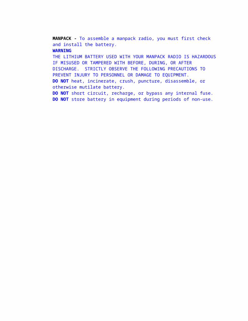
MANPACK - To assemble a manpack radio, you must first check and install the battery. WARNINGTHE LITHIUM BATTERY USED WITH YOUR MANPACK RADIO IS HAZARDOUS IF MISUSED OR TAMPERED WITH BEFORE, DURING, OR AFTER DISCHARGE. STRICTLY OBSERVE THE FOLLOWING PRECAUTIONS TO PREVENT INJURY TO PERSONNEL OR DAMAGE TO EQUIPMENT.DO NOT heat, incinerate, crush, puncture, disassemble, or otherwise mutilate battery.DO NOT short circuit, recharge, or bypass any internal fuse.DO NOT store battery in equipment during periods of non-use.
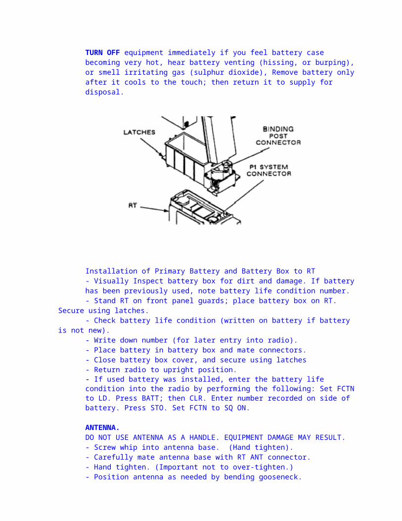
TURN OFF equipment immediately if you feel battery case becoming very hot, hear battery venting (hissing, or burping), or smell irritating gas (sulphur dioxide), Remove battery only after it cools to the touch; then return it to supply for disposal.
Installation of Primary Battery and Battery Box to RT- Visually Inspect battery box for dirt and damage. If battery has been previously used, note battery life condition number.- Stand RT on front panel guards; place battery box on RT. Secure using latches.- Check battery life condition (written on battery if battery is not new).- Write down number (for later entry into radio).- Place battery in battery box and mate connectors.- Close battery box cover, and secure using latches- Return radio to upright position.- If used battery was installed, enter the battery life condition into the radio by performing the following: Set FCTN to LD. Press BATT; then CLR. Enter number recorded on side of battery. Press STO. Set FCTN to SQ ON.
ANTENNA.DO NOT USE ANTENNA AS A HANDLE. EQUIPMENT DAMAGE MAY RESULT.- Screw whip into antenna base. (Hand tighten).- Carefully mate antenna base with RT ANT connector.- Hand tighten. (Important not to over-tighten.)- Position antenna as needed by bending gooseneck.
NOTE: Keep antenna straight up if possible. If the antenna is bent to a horizontal position, it may be necessary to turn the radio in order to receive and transmit messages.
HANDSETRefer to the illustration on page 2-18; then connect and secure handset connector to AUD/DATA connector. Make sure that keys line up on handset connector and RT AUD/DATA connector; then push handset connector onto AUD/DATA connector and twist right (clockwise) to lock in place. Push handset connector in and twist left (counterclockwise) to remove handset.FIELD PACKPlace RT in field pack with antenna on the left as shown.Fold top flap of field pack over RT and secure flap to field pack using strapsand buckles.Put on field pack

Vehicle Radio Component –Vehicular radios are installed and removed by maintenance personnel. However, if you have a dismount radio, you need to know how to remove and install the RT.WARNINGHIGH VOLTAGEEXISTS AT CONNECTOR J1 ON MOUNTING ADAPTER. AVOID INJURY: BE SURE J1 IS COVERED OR CAPPED WHEN NOT IN USE.CAUTIONBE SURE POWER SWITCH CB1 IS OFF WHEN REMOVING OR INSTALLING RT. IF IT IS NOT, EQUIPMENT DAMAGE MAY OCCUR.
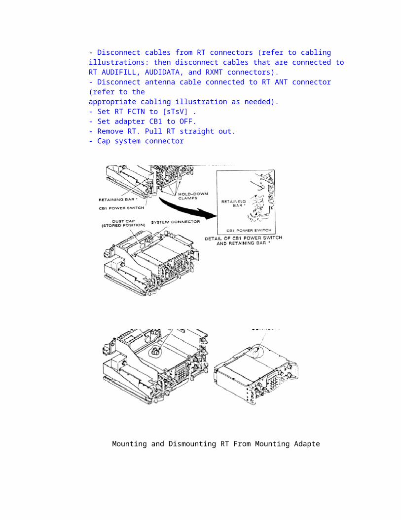
DISMOUNTING RT.When dismounting an RT to assemble a MP from a system that has two RT’s, always dismount the RT in position B (upper RT). You must use the RT in position B so that the radio system retains long range capability. This procedure will allow you to receive communication until step f has been performed.- Remove retaining bar (if used).- Loosen hold-down clamps; turn sideways.- Set CM (if used) to OFF.- Set loudspeaker (if used) power switch to OFF. - Disconnect cables from RT connectors (refer to cabling illustrations: then disconnect cables that are connected to RT AUDIFILL, AUDIDATA, and RXMT connectors).- Disconnect antenna cable connected to RT ANT connector (refer to the appropriate cabling illustration as needed).- Set RT FCTN to [sTsV] .- Set adapter CB1 to OFF.- Remove RT. Pull RT straight out.- Cap system connector

Mounting and Dismounting RT From Mounting Adapte
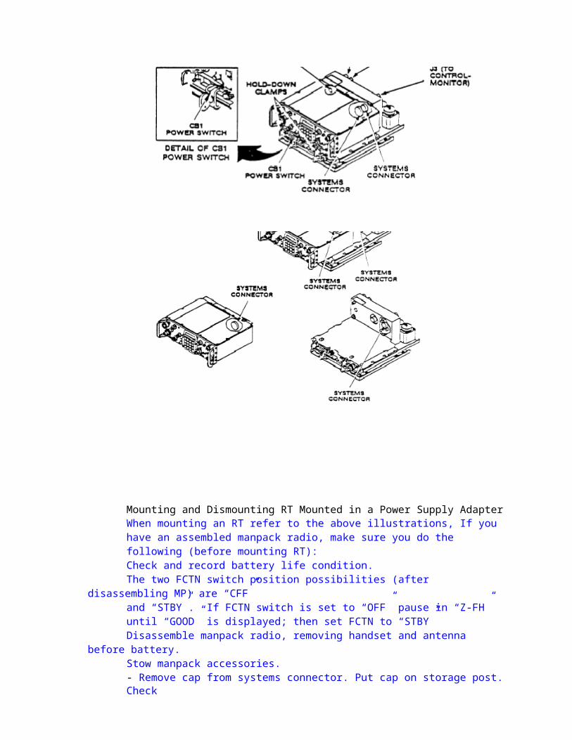
Mounting and Dismounting RT Mounted in a Power Supply Adapter
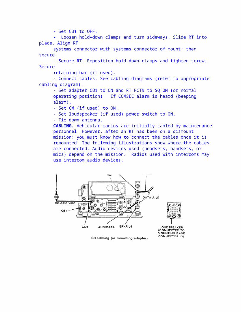
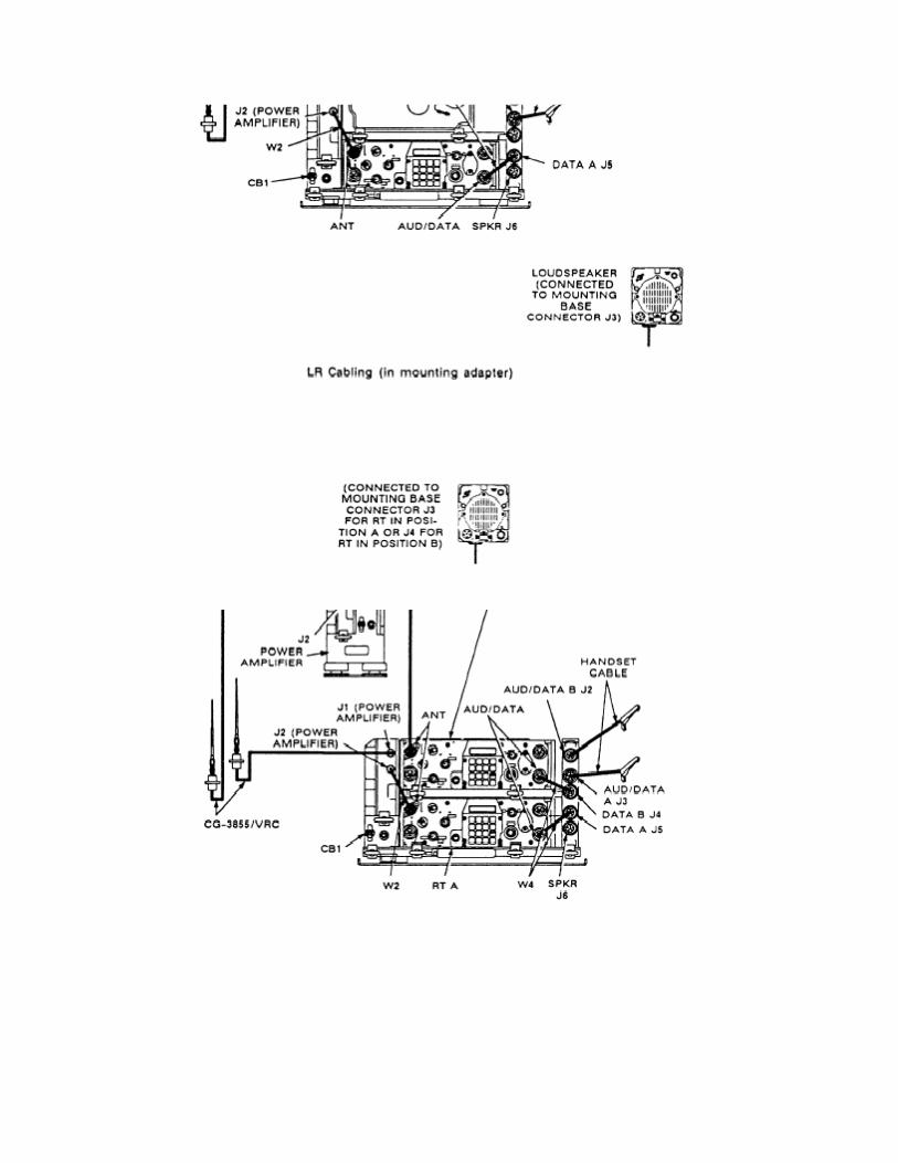
When mounting an RT refer to the above illustrations, If you have an assembled manpack radio, make sure you do the following (before mounting RT):Check and record battery life condition.The two FCTN switch position possibilities (after disassembling MP) are “CFF”and “STBY”. If FCTN switch is set to “OFF” pause in “Z-FH” until “GOOD” is displayed; then set FCTN to “STBY”Disassemble manpack radio, removing handset and antenna before battery.Stow manpack accessories.- Remove cap from systems connector. Put cap on storage post. Check- Set CB1 to OFF.- Loosen hold-down clamps and turn sideways. Slide RT into place. Align RTsystems connector with systems connector of mount: then secure.- Secure RT. Reposition hold-down clamps and tighten screws. Secure retaining bar (if used).- Connect cables. See cabling diagrams (refer to appropriate cabling diagram).- Set adapter CB1 to ON and RT FCTN to SQ ON (or normal operating position). If COMSEC alarm is heard (beeping alarm),- Set CM (if used) to ON.- Set loudspeaker (if used) power switch to ON.- Tie down antenna.CABLING. Vehicular radios are initially cabled by maintenance personnel. However, after an RT has been on a dismount mission: you must know how to connect the cables once it is remounted. The following illustrations show where the cables are connected. Audio devices used (headsets, handsets, or mics) depend on the mission. Radios used with intercoms may use intercom audio devices.
CAUTIONMAKE SURE YOU CONNECT CABLES EXACTLY AS SHOWN. EQUIPMENTDAMAGE MAY RESULT IF CABLES ARE INCORRECTLY CON-NECTED
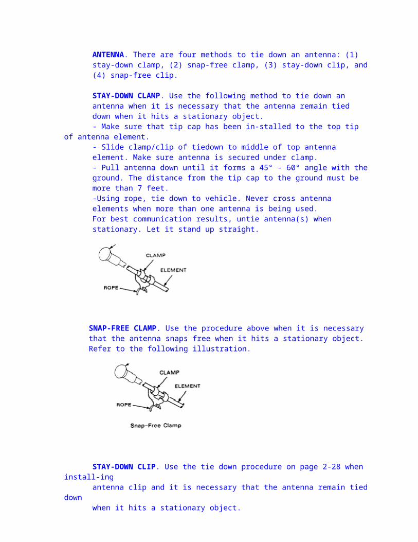
ANTENNA. There are four methods to tie down an antenna: (1) stay-down clamp, (2) snap-free clamp, (3) stay-down clip, and (4) snap-free clip.

STAY-DOWN CLAMP. Use the following method to tie down an antenna when it is necessary that the antenna remain tied down when it hits a stationary object.- Make sure that tip cap has been in-stalled to the top tip of antenna element.- Slide clamp/clip of tiedown to middle of top antenna element. Make sure antenna is secured under clamp.- Pull antenna down until it forms a 45° - 60° angle with the ground. The distance from the tip cap to the ground must be more than 7 feet.-Using rope, tie down to vehicle. Never cross antenna elements when more than one antenna is being used.For best communication results, untie antenna(s) when stationary. Let it stand up straight.
SNAP-FREE CLAMP. Use the procedure above when it is necessary that the antenna snaps free when it hits a stationary object. Refer to the following illustration.
STAY-DOWN CLIP. Use the tie down procedure on page 2-28 when install-ingantenna clip and it is necessary that the antenna remain tied downwhen it hits a stationary object.
SNAP-FREE CLIP. Use the tie down procedure on page 2-28 when installing antenna clip and it is necessary that the antenna snaps free when it hits a stationary object.
109.4 Explain the procedures for loading single channel frequencies. [ref. a, pp. 2-33, 2-34]
LOADING SC FREQUENCIES. The procedure for loading SC frequencies requires setting the proper switches, pressing the correct number keys for the frequency you wish to load, and storing the load in RT permanent memory by pressing STO button.- Obtain authorized operating frequency from SOI or NCS.- Refer to the illustration of RT front panel above: then set FCTN to LD.- Set MODE to SC.- Set CHAN to MAN, CUE, or desired channel (1 - 6) where frequency is to be stored.- Press FREQ (display will show "00000", or to frequency RT is currently tuned).- Press CLR (display will show five lines).
- Enter the numbers of the new frequency (using keyboard buttons).If you make a mistake while entering a frequency, press CLR (this action will delete the last digit entered)..It is important that you enter another number, or store the frequency within 7 seconds. Otherwise, the display will go blank, and you will have
to re-enter the numbers. If you require more than 7 seconds to perform a step, continue to press the last button, and the 7 second clock will be stopped.- Press STO (display will blink and show the frequency you just stored).- Repeat steps a thru h for additional frequencies that you wish to load.- Set FCTN to SQ ON (or normal operating position).
109.5 Discuss the purpose of the following batteries: [ref. a, p. C-1]
BA 5372 - BATTERY, NON-RECHARGEABLE BA-5372/U (hold up battery)BA 5590 - BATTERY, NON-RECHARGEABLE (Lithium) (manpack radio primary power battery) BA 590 - BATTERY, RECHARGEABLE: BB (manpack radio secondary power battery
109.6 Discuss the phonetic alphabet. [ref. b, p. 1-19-14]
PHONETIC ALPHABET PRONUNCIATIONA = ALFAB = BRAVOC = CHARLIED = DELTAE = ECHOF = FOXTROTG = GOLFH = HOTELI = INDIAJ = JULIETK = KILOL = LIMAM = MIKE
N = NOVEMBERO = OSCARP = PAPAQ = QUEBECR = ROMEOS = SIERRAT = TANGOU = UNIFORMV = VICTORW = WHISKEYX = X-RAYY = YANKEEZ = ZULU
A = AL FAHB = BRAH VOHC = CHAR LEED = DELL TAHE = ECH OHF = FOKS TROTG = GOLFH = HOH TELLI = IN DEE AHJ = JEW LEE ETTK = KEY LOHL = LEE MAHM = MIKE
N = NO VEM BERO = OSS CAHP = PAH PAHQ = KEH BECKR = ROW ME OHS = SEE AIR RAHT = TANG GOU = YOU NEE FORMV = VIK TAHW = WISS KEYX = ECKS RAYY = YANG KEYZ = ZOO LOO
NUMERIC PRONUNCIATION1 = WUN2 = TOO3 = TREE4 = FO-WER5 = FIFE
6 = SIX7 = SEV-EN8 = ATE9 = NIN-ER0 = ZE-RO
70 = SEVEN ZERO84 = ATE FO-WER131 = WUN TREE WUN500 = FIFE HUN-DRED1,468 = WUN FO-WER SIX ATE7,000 = SEVEN THOUSAND16,000 = WUN SIX THOUSAND
109.7 Discuss the procedures to perform operator's level maintenance on theAN/PRC 119. [ref. b, pp. 1-19-16, 1-19-17]
Inspect the equipment.

Ensure the equipment SL3 is complete.Check all major components for damage and serviceability.- Receiver-transmitter- Battery box- Antennas and support bases- Harness and accessory bag- Headset or handset.
Clean the equipment- Inspect the exterior of the radio set.- Clean the external surface by removing dust, dirt, grease, salt, and fungus.- Remove all dust and loose dirt with a clean rag and a general-purpose brush - Clean the audio connector pins on the radio and handset with a rubber eraser.
Perform operation checks.Conduct inventory. Make sure all parts are present.Check the accessories for cleanliness and serviceability using the memory aid
FITCAL.Feel. Physically touch and inspect the radio set and its accessories.Inspect. Visually inspect gear for cracks or corrosion.Tighten. Tighten all connectors by hand and make sure all screws are tight.Clean. Clean with brushes and rags.Adjust. Adjust all controls and knobs to ensure serviceability.Lubricate. Lubricate rubber boots and handset cords with silicone to prevent dry rot.
Report any discrepancies
Related Documents