100 A tap-changer switch cap/wrench, lever or hotstick operable handles installation instructions COOPER POWER SERIES OEM Equipment MN800014EN Effective February 2017 Supersedes August 2012 (S800-57-1)

Welcome message from author
This document is posted to help you gain knowledge. Please leave a comment to let me know what you think about it! Share it to your friends and learn new things together.
Transcript
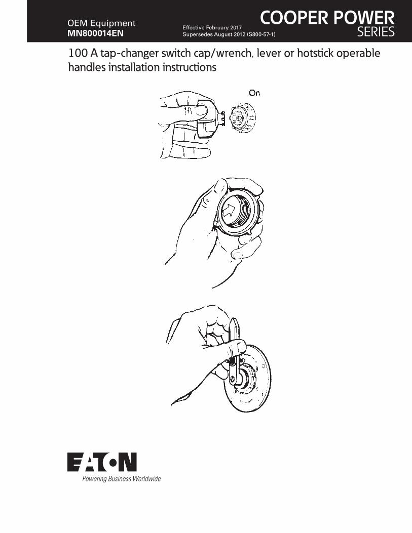
100 A tap-changer switch cap/wrench, lever or hotstick operable handles installation instructions
COOPER POWERSERIES
OEM EquipmentMN800014EN
Effective February 2017 Supersedes August 2012 (S800-57-1)
iINSTALLATION INSTRUCTIONS MN800014EN February 2017
DISCLAIMER OF WARRANTIES AND LIMITATION OF LIABILITY
The information, recommendations, descriptions and safety notations in this document are based on Eaton Corporation’s (“Eaton”) experience and judgment and may not cover all contingencies. If further information is required, an Eaton sales office should be consulted. Sale of the product shown in this literature is subject to the terms and conditions outlined in appropriate Eaton selling policies or other contractual agreement between Eaton and the purchaser.
THERE ARE NO UNDERSTANDINGS, AGREEMENTS, WARRANTIES, EXPRESSED OR IMPLIED, INCLUDING WARRANTIES OF FITNESS FOR A PARTICULAR PURPOSE OR MERCHANTABILITY, OTHER THAN THOSE SPECIFICALLY SET OUT IN ANY EXISTING CONTRACT BETWEEN THE PARTIES. ANY SUCH CONTRACT STATES THE ENTIRE OBLIGATION OF EATON. THE CONTENTS OF THIS DOCUMENT SHALL NOT BECOME PART OF OR MODIFY ANY CONTRACT BETWEEN THE PARTIES.
In no event will Eaton be responsible to the purchaser or user in contract, in tort (including negligence), strict liability or other-wise for any special, indirect, incidental or consequential damage or loss whatsoever, including but not limited to damage or loss of use of equipment, plant or power system, cost of capital, loss of power, additional expenses in the use of existing power facilities, or claims against the purchaser or user by its customers resulting from the use of the information, recommendations and descriptions contained herein. The information contained in this manual is subject to change without notice.
Contents
DISCLAIMER OF WARRANTIES AND LIMITATION OF LIABILITY . . . . . . . . . . . . . . . . . . . . . . . . . . . . . . . . . . . . I
SAFETY FOR LIFE . . . . . . . . . . . . . . . . . . . . . . . . . . . . . . . . . . . . . . . . . . . . . . . . . . . . . . . . . . . . . . . . . . . . . . . . . III
SAFETY INFORMATION . . . . . . . . . . . . . . . . . . . . . . . . . . . . . . . . . . . . . . . . . . . . . . . . . . . . . . . . . . . . . . . . . . . . IIISafety instructions . . . . . . . . . . . . . . . . . . . . . . . . . . . . . . . . . . . . . . . . . . . . . . . . . . . . . . . . . . . . . . . . . . . . . . . . . . . . . . iii
PRODUCT INFORMATION . . . . . . . . . . . . . . . . . . . . . . . . . . . . . . . . . . . . . . . . . . . . . . . . . . . . . . . . . . . . . . . . . . . 1Introduction . . . . . . . . . . . . . . . . . . . . . . . . . . . . . . . . . . . . . . . . . . . . . . . . . . . . . . . . . . . . . . . . . . . . . . . . . . . . . . . . . . . .1
Read this manual first . . . . . . . . . . . . . . . . . . . . . . . . . . . . . . . . . . . . . . . . . . . . . . . . . . . . . . . . . . . . . . . . . . . . . . . . . . . .1
Additional information . . . . . . . . . . . . . . . . . . . . . . . . . . . . . . . . . . . . . . . . . . . . . . . . . . . . . . . . . . . . . . . . . . . . . . . . . . . .1
Acceptance and initial inspection . . . . . . . . . . . . . . . . . . . . . . . . . . . . . . . . . . . . . . . . . . . . . . . . . . . . . . . . . . . . . . . . . . .1
Handling and storage . . . . . . . . . . . . . . . . . . . . . . . . . . . . . . . . . . . . . . . . . . . . . . . . . . . . . . . . . . . . . . . . . . . . . . . . . . . . .1
Standards . . . . . . . . . . . . . . . . . . . . . . . . . . . . . . . . . . . . . . . . . . . . . . . . . . . . . . . . . . . . . . . . . . . . . . . . . . . . . . . . . . . . .1
GENERAL MOUNTING DESCRIPTION . . . . . . . . . . . . . . . . . . . . . . . . . . . . . . . . . . . . . . . . . . . . . . . . . . . . . . . . . 1Torque requirements . . . . . . . . . . . . . . . . . . . . . . . . . . . . . . . . . . . . . . . . . . . . . . . . . . . . . . . . . . . . . . . . . . . . . . . . . . . . .1
Clearance . . . . . . . . . . . . . . . . . . . . . . . . . . . . . . . . . . . . . . . . . . . . . . . . . . . . . . . . . . . . . . . . . . . . . . . . . . . . . . . . . . . . . .1
Mechanical strength . . . . . . . . . . . . . . . . . . . . . . . . . . . . . . . . . . . . . . . . . . . . . . . . . . . . . . . . . . . . . . . . . . . . . . . . . . . . .1
Electrical ratings . . . . . . . . . . . . . . . . . . . . . . . . . . . . . . . . . . . . . . . . . . . . . . . . . . . . . . . . . . . . . . . . . . . . . . . . . . . . . . . .1
Operation instructions . . . . . . . . . . . . . . . . . . . . . . . . . . . . . . . . . . . . . . . . . . . . . . . . . . . . . . . . . . . . . . . . . . . . . . . . . . . .2
Cap/wrench switches . . . . . . . . . . . . . . . . . . . . . . . . . . . . . . . . . . . . . . . . . . . . . . . . . . . . . . . . . . . . . . . . . . . . . . . . . . . .2
Lever or hotstick handle switches . . . . . . . . . . . . . . . . . . . . . . . . . . . . . . . . . . . . . . . . . . . . . . . . . . . . . . . . . . . . . . . . . . .2
Mounting sequence . . . . . . . . . . . . . . . . . . . . . . . . . . . . . . . . . . . . . . . . . . . . . . . . . . . . . . . . . . . . . . . . . . . . . . . . . . . . .3
ii INSTALLATION INSTRUCTIONS MN800014EN February 2017
The instructions in this manual are not intended as a sub stitute for proper training or adequate experience in the safe operation of the equipment described. Only competent technicians, who are familiar with this equipment should install, operate and service it.
A competent technician has these qualifications:
• Is thoroughly familiar with these instructions.
• Is trained in industry-accepted high- and low-voltage safe operating practices and procedures.
• Is trained and authorized to energize, de-energize, clear, and ground power distribution equipment.
• Is trained in the care and use of protective equipment such as flash clothing, safety glasses, face shield, hard hat, rubber gloves, clampstick, hotstick, etc.
Following is important safety information. For safe installation and operation of this equipment, be sure to read and understand all cautions and warnings.
Safety instructionsFollowing are general caution and warning statements that apply to this equipment. Additional statements, related to specific tasks and procedures, are located throughout the manual.
Safety for life!
SAFETYFOR LIFE
!SAFETYFOR LIFE
Eaton’s Cooper Power series products meet or exceed all applicable industry standards relating to product safety. We actively promote safe practices in the use and maintenance of our products through our service literature, instructional training programs, and the continuous efforts of all Eaton employees involved in product design, manufacture, marketing and service.
We strongly urge that you always follow all locally approved safety procedures and safety instructions when working around high-voltage lines and equipment and support our “Safety For Life” mission.
Safety information
DANGERHazardous voltage . Contact with high voltage will cause death or severe personal injury . Follow all locally approved safety procedures when working around high- and low-voltage lines and equipment .
WARNING Before installing, operating, maintaining, or testing this equipment, carefully read and understand the contents of this manual . Improper operation, handling or maintenance can result in death, severe personal injury, and equipment damage .
WARNING This equipment is not intended to protect human life . Follow all locally approved procedures and safety practices when installing or operating this equipment . Failure to comply may result in death, severe personal injury and equipment damage .
WARNING Power distribution and transmission equipment must be properly selected for the intended application . It must be installed and serviced by competent personnel who have been trained and understand proper safety procedures . These instructions are written for such personnel and are not a substitute for adequate training and experience in safety procedures . Failure to properly select, install or maintain power distribution and transmission equipment can result in death, severe personal injury, and equipment damage .
This manual may contain four types of hazard statements:
DANGER Indicates a hazardous situation which, if not avoided, will result in death or serious injury .
WARNING Indicates a hazardous situation which, if not avoided, could result In death or serious injury .
CAUTION Indicates a hazardous situation which, if not avoided, could result in minor or moderate injury .
CAUTIONIndicates a hazardous situation which, if not avoided, could result in equipment damage only .
Hazard Statement Definitions
iiiINSTALLATION INSTRUCTIONS MN800014EN February 2017
Product information
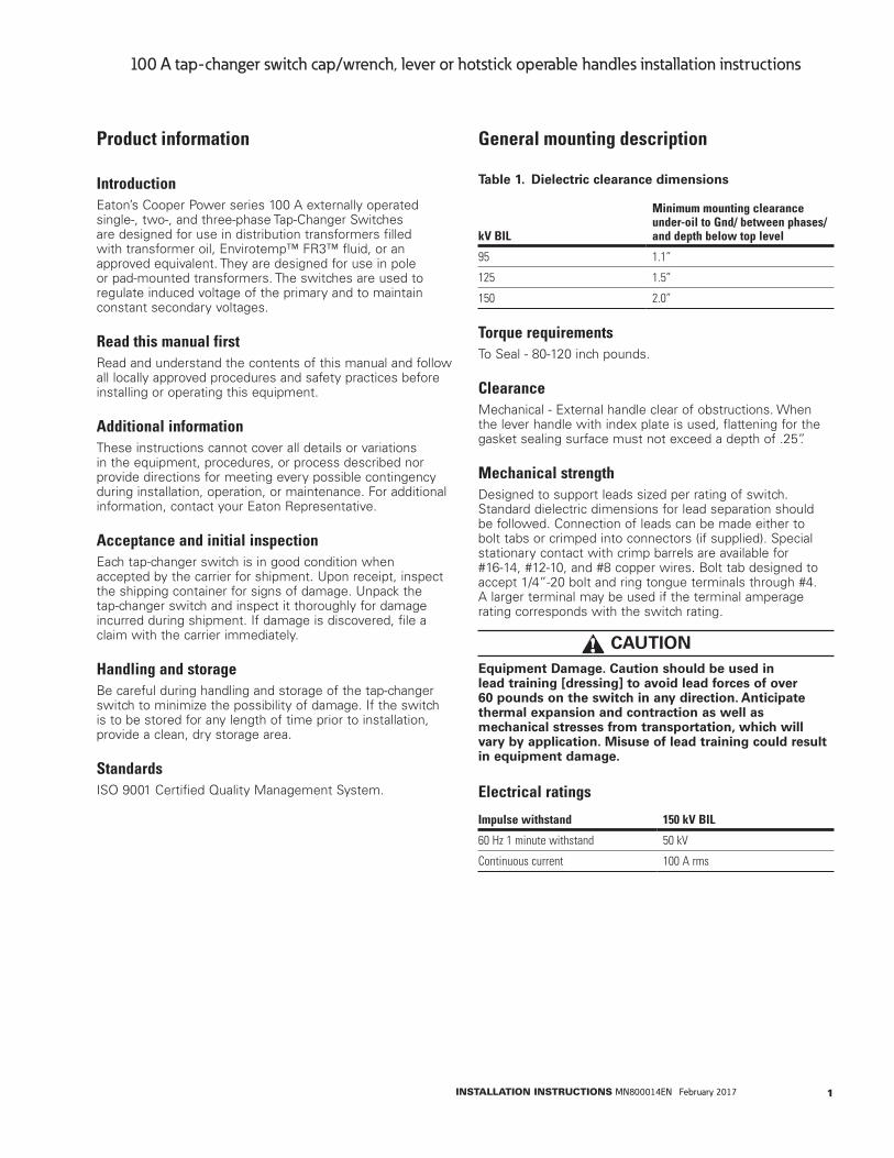
IntroductionEaton’s Cooper Power series 100 A externally operated single-, two-, and three-phase Tap-Changer Switches are designed for use in distribution transformers filled with transformer oil, Envirotemp™ FR3™ fluid, or an approved equivalent. They are designed for use in pole or pad-mounted transformers. The switches are used to regulate induced voltage of the primary and to maintain constant secondary voltages.
Read this manual firstRead and understand the contents of this manual and follow all locally approved procedures and safety practices before installing or operating this equipment.
Additional informationThese instructions cannot cover all details or variations in the equipment, procedures, or process described nor provide directions for meeting every possible contingency during installation, operation, or maintenance. For additional information, contact your Eaton Representative.
Acceptance and initial inspectionEach tap-changer switch is in good condition when accepted by the carrier for shipment. Upon receipt, inspect the shipping container for signs of damage. Unpack the tap-changer switch and inspect it thoroughly for damage incurred during shipment. If damage is discovered, file a claim with the carrier immediately.
Handling and storageBe careful during handling and storage of the tap-changer switch to minimize the possibility of damage. If the switch is to be stored for any length of time prior to installation, provide a clean, dry storage area.
StandardsISO 9001 Certified Quality Management System.
General mounting description
Table 1 . Dielectric clearance dimensions
kV BIL
Minimum mounting clearance under-oil to Gnd/ between phases/ and depth below top level
95 1.1”
125 1.5”
150 2.0”
Torque requirementsTo Seal - 80-120 inch pounds.
ClearanceMechanical - External handle clear of obstructions. When the lever handle with index plate is used, flattening for the gasket sealing surface must not exceed a depth of .25”.
Mechanical strengthDesigned to support leads sized per rating of switch. Standard dielectric dimensions for lead separation should be followed. Connection of leads can be made either to bolt tabs or crimped into connectors (if supplied). Special stationary contact with crimp barrels are available for #16-14, #12-10, and #8 copper wires. Bolt tab designed to accept 1/4”-20 bolt and ring tongue terminals through #4. A larger terminal may be used if the terminal amperage rating corresponds with the switch rating.
CAUTIONEquipment Damage . Caution should be used in lead training [dressing] to avoid lead forces of over 60 pounds on the switch in any direction . Anticipate thermal expansion and contraction as well as mechanical stresses from transportation, which will vary by application . Misuse of lead training could result in equipment damage .
Electrical ratings
Impulse withstand 150 kV BIL
60 Hz 1 minute withstand 50 kV
Continuous current 100 A rms
1INSTALLATION INSTRUCTIONS MN800014EN February 2017
100 A tap-changer switch cap/wrench, lever or hotstick operable handles installation instructions
Operation instructions
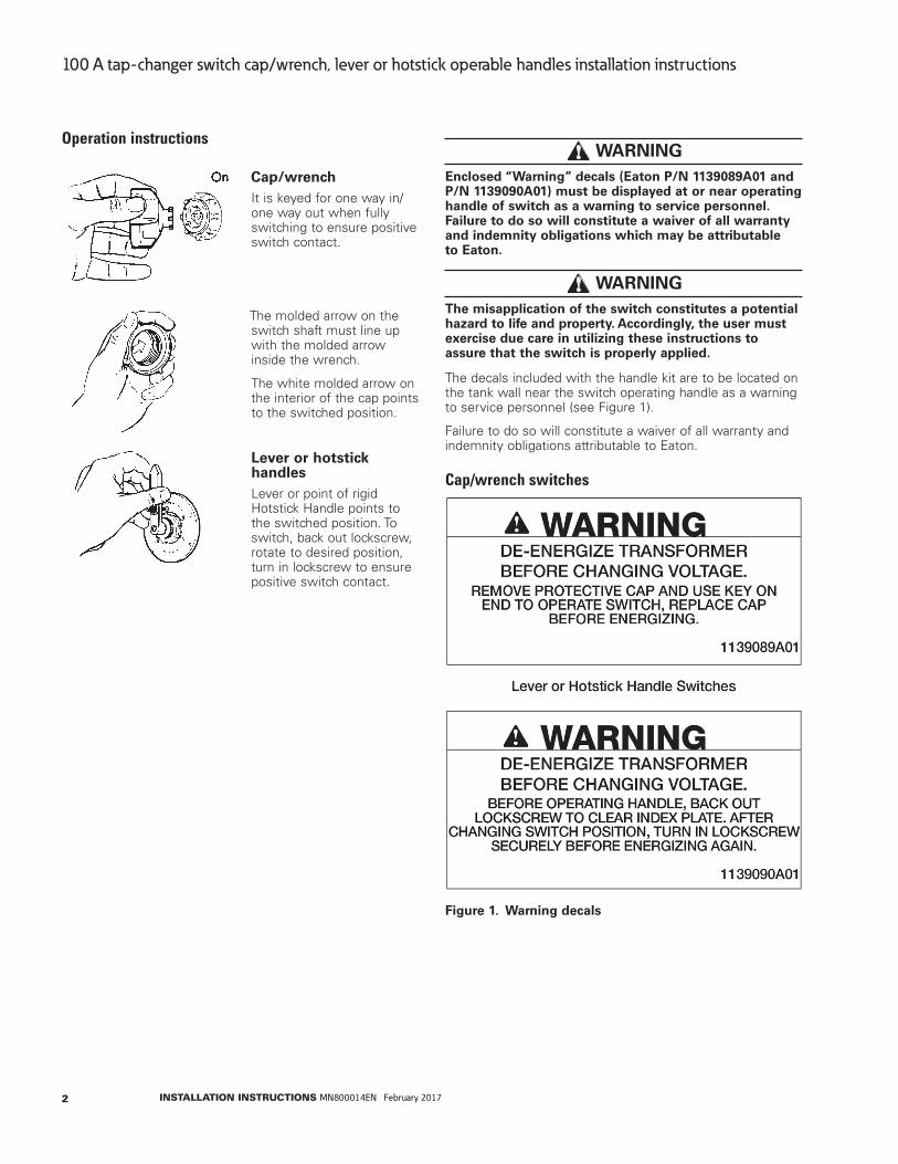
Cap/wrenchIt is keyed for one way in/one way out when fully switching to ensure positive switch contact.
The molded arrow on the switch shaft must line up with the molded arrow inside the wrench.
The white molded arrow on the interior of the cap points to the switched position.
Lever or hotstick handlesLever or point of rigid Hotstick Handle points to the switched position. To switch, back out lockscrew, rotate to desired position, turn in lockscrew to ensure positive switch contact.
WARNING Enclosed “Warning” decals (Eaton P/N 1139089A01 and P/N 1139090A01) must be displayed at or near operating handle of switch as a warning to service personnel . Failure to do so will constitute a waiver of all warranty and indemnity obligations which may be attributable to Eaton .
WARNING The misapplication of the switch constitutes a potential hazard to life and property . Accordingly, the user must exercise due care in utilizing these instructions to assure that the switch is properly applied .
The decals included with the handle kit are to be located on the tank wall near the switch operating handle as a warning to service personnel (see Figure 1).
Failure to do so will constitute a waiver of all warranty and indemnity obligations attributable to Eaton.
Cap/wrench switches
Figure 1 . Warning decals
2 INSTALLATION INSTRUCTIONS MN800014EN February 2017
100 A tap-changer switch cap/wrench, lever or hotstick operable handles installation instructions
Mounting sequence
100 A Tap-Changer Switch - Cap/Wrench, Lever or Hotstick Operable Handles Installation Instructions
4
mounting Sequence
Cap/Wrench
Nut
Tank Wall
Gasket
Switch
NOTES: Switch can be used on 14 gauge to �25 inch thick frontplate� Bolt tabs are bent up 90° and have a hole to accept �25 inch
(6 mm) hardware�
Figure 2.
Cap/Wrench Assembly.
Figure 3.
One-Phase Cap Wrench Switch.
* Dimension will decrease as tank wall thickness increases� Maximum dimension given with 14 gauge tank wall�
Figure 4.
Cap Wrench - Front View.
Screw
LockwasherFlat Washer
Metal or Thermoplastic Lever Handle
Nut
Tank Wall
Index Plate
Gasket
Switch
Figure 5.
Lever Assembly.
Figure 6.
One-Phase Lever Handle Switch.
* Dimension will decrease as tank wall thickness increases� Maximum dimension given with 14 gauge tank wall�
Figure 7.
Lever Handle - Front View.* Dimension will decrease as tank wall thickness increases� Maximum dimension
given with 14 gauge tank wall�
Cap/Wrench
Nut
Tank Wall
Gasket
Switch
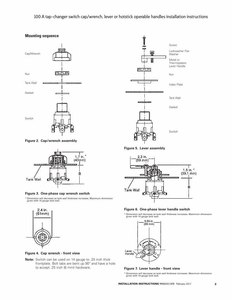
Figure 2 . Cap/wrench assembly
100 A Tap-Changer Switch - Cap/Wrench, Lever or Hotstick Operable Handles Installation Instructions
4
mounting Sequence
Cap/Wrench
Nut
Tank Wall
Gasket
Switch
NOTES: Switch can be used on 14 gauge to �25 inch thick frontplate� Bolt tabs are bent up 90° and have a hole to accept �25 inch
(6 mm) hardware�
Figure 2.
Cap/Wrench Assembly.
Figure 3.
One-Phase Cap Wrench Switch.
* Dimension will decrease as tank wall thickness increases� Maximum dimension given with 14 gauge tank wall�
Figure 4.
Cap Wrench - Front View.
Screw
LockwasherFlat Washer
Metal or Thermoplastic Lever Handle
Nut
Tank Wall
Index Plate
Gasket
Switch
Figure 5.
Lever Assembly.
Figure 6.
One-Phase Lever Handle Switch.
* Dimension will decrease as tank wall thickness increases� Maximum dimension given with 14 gauge tank wall�
Figure 7.
Lever Handle - Front View.* Dimension will decrease as tank wall thickness increases� Maximum dimension
given with 14 gauge tank wall�
Figure 3 . One-phase cap wrench switch* Dimension will decrease as tank wall thickness increases. Maximum dimension
given with 14 gauge tank wall.
Figure 4 . Cap wrench - front view
otee:N Switch can be used on 14 gauge to .25 inch thick frontplate. Bolt tabs are bent up 90° and have a hole to accept .25 inch (6 mm) hardware.
Screw
Lockwasher Flat Washer
Metal or Thermoplastic Lever Handle
Nut
Tank Wall
Index Plate
Gasket
Switch
Figure 5 . Lever assembly
Figure 6 . One-phase lever handle switch* Dimension will decrease as tank wall thickness increases. Maximum dimension
given with 14 gauge tank wall.
Figure 7 . Lever handle - front view* Dimension will decrease as tank wall thickness increases. Maximum dimension
given with 14 gauge tank wall.
3INSTALLATION INSTRUCTIONS MN800014EN February 2017
100 A tap-changer switch cap/wrench, lever or hotstick operable handles installation instructions
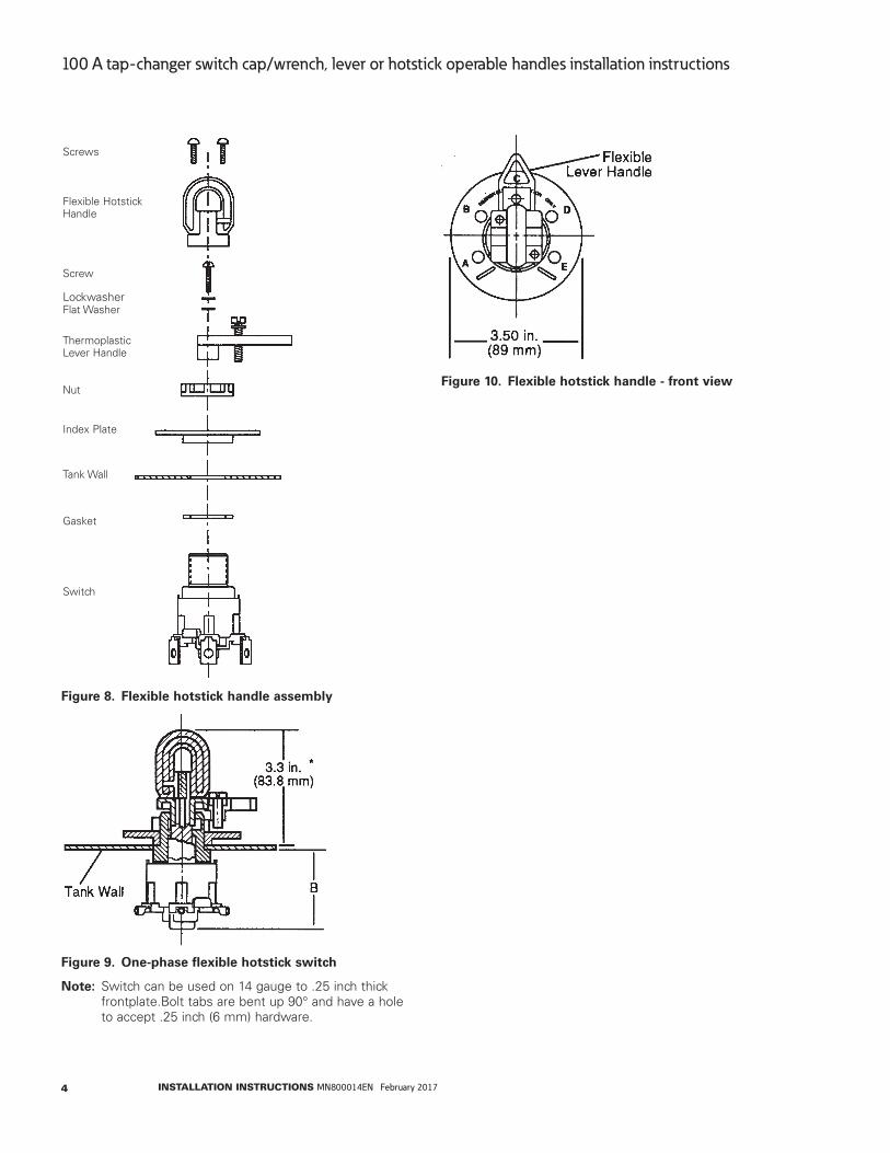
Screws
Lockwasher Flat Washer
Screw
Nut
Index Plate
Flexible Hotstick Handle
Thermoplastic Lever Handle
Tank Wall
Gasket
Switch
Figure 8 . Flexible hotstick handle assembly
Figure 9 . One-phase flexible hotstick switch
otee:N Switch can be used on 14 gauge to .25 inch thick frontplate.Bolt tabs are bent up 90° and have a hole to accept .25 inch (6 mm) hardware.
Figure 10 . Flexible hotstick handle - front view
4 INSTALLATION INSTRUCTIONS MN800014EN February 2017
100 A tap-changer switch cap/wrench, lever or hotstick operable handles installation instructions
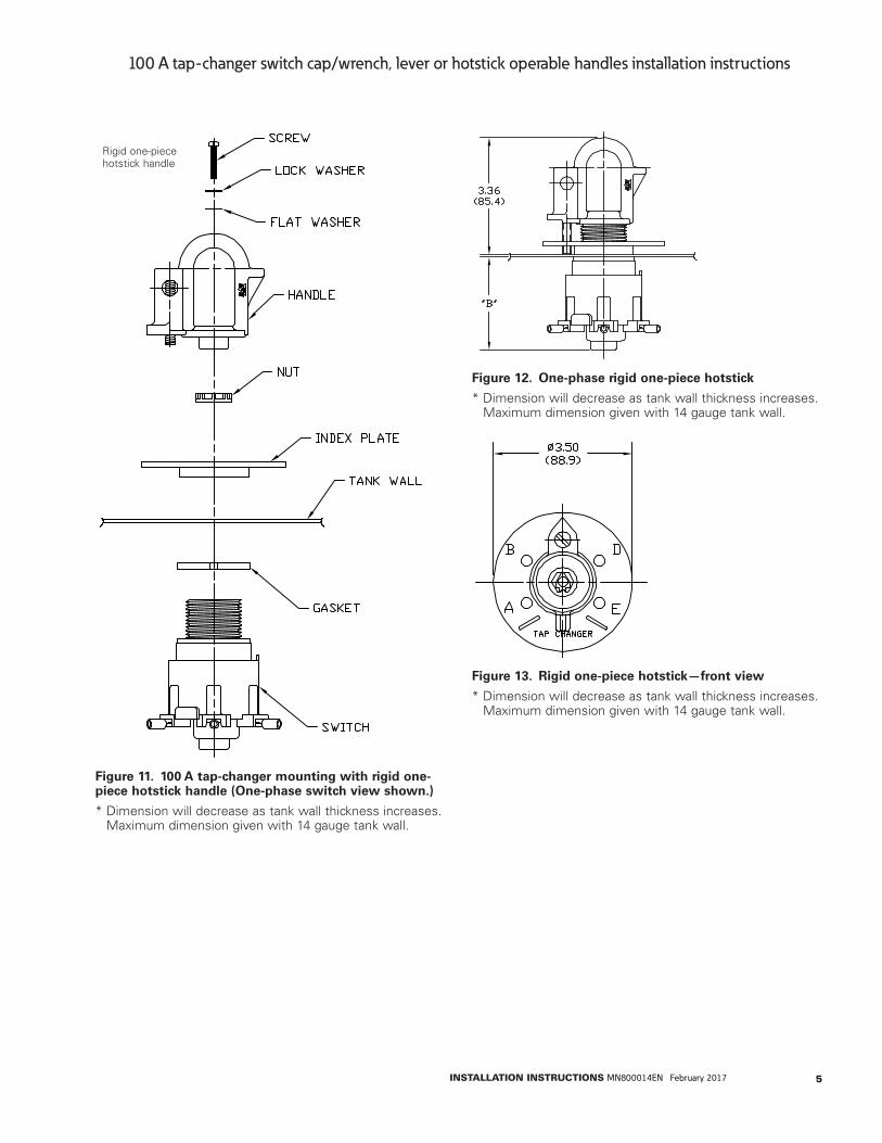
Rigid one-piece hotstick handle
Figure 11 . 100 A tap-changer mounting with rigid one-piece hotstick handle (One-phase switch view shown .)
* Dimension will decrease as tank wall thickness increases. Maximum dimension given with 14 gauge tank wall.
Figure 12 . One-phase rigid one-piece hotstick
* Dimension will decrease as tank wall thickness increases. Maximum dimension given with 14 gauge tank wall.
Figure 13 . Rigid one-piece hotstick—front view
* Dimension will decrease as tank wall thickness increases. Maximum dimension given with 14 gauge tank wall.
5INSTALLATION INSTRUCTIONS MN800014EN February 2017
100 A tap-changer switch cap/wrench, lever or hotstick operable handles installation instructions
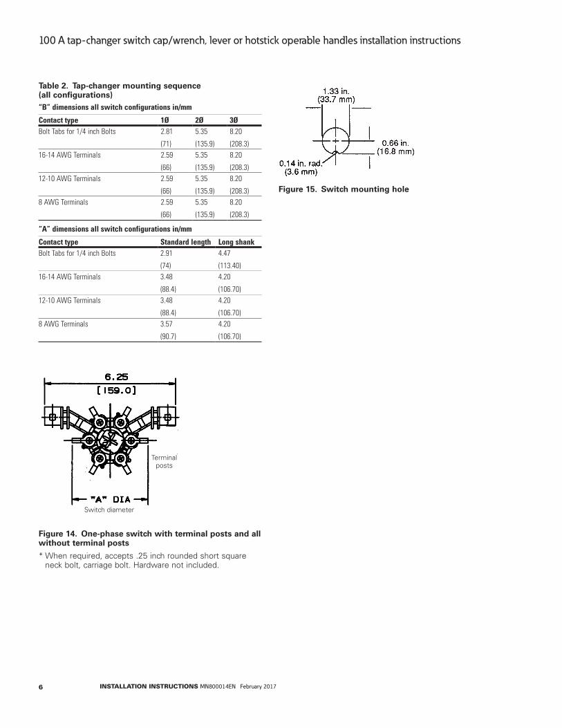
Table 2 . Tap-changer mounting sequence (all configurations)“B” dimensions all switch configurations in/mm
Contact type 1Ø 2Ø 3ØBolt Tabs for 1/4 inch Bolts 2.81
(71)
5.35
(135.9)
8.20
(208.3)16-14 AWG Terminals 2.59
(66)
5.35
(135.9)
8.20
(208.3)12-10 AWG Terminals 2.59
(66)
5.35
(135.9)
8.20
(208.3)8 AWG Terminals 2.59
(66)
5.35
(135.9)
8.20
(208.3)
“A” dimensions all switch configurations in/mm
Contact type Standard length Long shankBolt Tabs for 1/4 inch Bolts 2.91
(74)
4.47
(113.40)16-14 AWG Terminals 3.48
(88.4)
4.20
(106.70)12-10 AWG Terminals 3.48
(88.4)
4.20
(106.70)8 AWG Terminals 3.57
(90.7)
4.20
(106.70)
Figure 14 . One-phase switch with terminal posts and all without terminal posts
* When required, accepts .25 inch rounded short square neck bolt, carriage bolt. Hardware not included.
Switch diameter
Terminal posts
Figure 15 . Switch mounting hole
6 INSTALLATION INSTRUCTIONS MN800014EN February 2017
100 A tap-changer switch cap/wrench, lever or hotstick operable handles installation instructions

This page intentionally left blank.
7INSTALLATION INSTRUCTIONS MN800014EN February 2017
100 A tap-changer switch cap/wrench, lever or hotstick operable handles installation instructions

Eaton1000 Eaton BoulevardCleveland, OH 44122United StatesEaton.com
Eaton’s Power Systems Division2300 Badger DriveWaukesha, WI 53188United StatesEaton.com/cooperpowerseries
© 2017 EatonAll Rights ReservedPrinted in USAPublication No. MN800014EN / Rev. 1Supersedes S800571 Rev. 3February 2017
Eaton is a registered trademark.
All trademarks are property of their respective owners.
For Eaton’s Cooper Power series product information call 1-877-277-4636 or visit: www.eaton.com/cooperpowerseries.
!SAFETYFOR LIFE
Related Documents