CHAPTER 1 Routing Concepts 1.0 Routing Concepts 1.0.1.1 Introduction Networks allow people to communicate, collaborate, and interact in many ways. Networks are used to access web pages, talk using IP telephones, participate in video conferences, compete in interactive gaming, shop using the Internet, complete online coursework, and more. At the core of the network is the router. A router connects one network to another network. The router is responsible for the delivery of packets across different networks. The destination of the IP packet might be a web server in another country or an email server on the local area network. The router uses its routing table to determine the best path to use to forward a packet. It is the responsibility of the routers to deliver those packets in a timely manner. The effectiveness of internetwork communications depends, to a large degree, on the ability of routers to forward packets in the most efficient way possible. When a host sends a packet to a device on a different IP network, the packet is forwarded to the default gateway because a host device cannot communicate directly with devices outside of the local network. The default gateway is the destination that routes traffic from the local network to devices on remote networks. It is often used to connect a local network to the Internet. This chapter will also answer the question, “What does a router do with a packet received from one network and destined for another network?” Details of the routing table will be examined including connected, static, and dynamic routes. Because the router can route packets between networks, devices on different networks can communicate. This chapter will introduce the router, its role in the networks, its main hardware and software components, and the routing process. Exercises which demonstrate how to access the router, configure basic router settings, and verify settings will be provided. 1.0.1.2 Class Activity - Do We Really Need a Map? Activity - Do We Really Need a Map? This modeling activity asks you to research travel directions from source to destination. Its purpose is to compare those types of directions to network routing directions. Scenario Using the Internet and Google Maps, located at http://maps.google.com, find a route between the capital city of your country and some other distant town or between two places within your own city. Pay close attention to the driving or walking directions Google Maps suggests. Refer to Lab Activity for this chapter

Welcome message from author
This document is posted to help you gain knowledge. Please leave a comment to let me know what you think about it! Share it to your friends and learn new things together.
Transcript
Chapter 1
routing Concepts
1.0 routing Concepts
1.0.1.1 Introduction
Networks allow people to communicate, collaborate, and interact in many ways. Networks are used to access web pages, talk using IP telephones, participate in video conferences, compete in interactive gaming, shop using the Internet, complete online coursework, and more.
At the core of the network is the router. A router connects one network to another network. The router is responsible for the delivery of packets across different networks. The destination of the IP packet might be a web server in another country or an email server on the local area network.
The router uses its routing table to determine the best path to use to forward a packet. It is the responsibility of the routers to deliver those packets in a timely manner. The effectiveness of internetwork communications depends, to a large degree, on the ability of routers to forward packets in the most efficient way possible.
When a host sends a packet to a device on a different IP network, the packet is forwarded to the default gateway because a host device cannot communicate directly with devices outside of the local network. The default gateway is the destination that routes traffic from the local network to devices on remote networks. It is often used to connect a local network to the Internet.
This chapter will also answer the question, “What does a router do with a packet received from one network and destined for another network?” Details of the routing table will be examined including connected, static, and dynamic routes.
Because the router can route packets between networks, devices on different networks can communicate. This chapter will introduce the router, its role in the networks, its main hardware and software components, and the routing process. Exercises which demonstrate how to access the router, configure basic router settings, and verify settings will be provided.
1.0.1.2 Class Activity - Do We Really Need a Map?Activity - Do We Really Need a Map?
This modeling activity asks you to research travel directions from source to destination. Its purpose is to compare those types of directions to network routing directions.
Scenario
Using the Internet and Google Maps, located at http://maps.google.com, find a route between the capital city of your country and some other distant town or between two places within your own city. Pay close attention to the driving or walking directions Google Maps suggests.
Refer toLab Activityfor this chapter

6 Routing Protocols Course Booklet
Notice that in many cases, Google Maps suggests more than one route between the two locations you chose. It also allows you to put additional constraints on the route, such as avoiding highways or tolls.
Copy at least two route instructions supplied by Google Maps for this activity. Place your copies into a word processing document and save it for use with the next step.
Open the .pdf accompanying this modeling activity and complete it with a fellow student. Discuss the reflection questions listed on the .pdf and record your answers.
Be prepared to present your answers to the class.
1.1 Initial Configuration of a router
1.1.1 Functions of a router
1.1.1.1 Characteristics of a NetworkNetworks have had a significant impact on our lives. They have changed the way we live, work, and play.
Networks allow us to communicate, collaborate, and interact in ways we never did before. We use the network in a variety of ways, including web applications, IP telephony, video conferencing, interactive gaming, electronic commerce, education, and more.
As shown in the figure, there are many key structures and performance-related characteris-tics referred to when discussing networks:
■ Topology - There are physical and logical topologies. The physical topology is the arrangement of the cables, network devices, and end systems. It describes how the network devices are actually interconnected with wires and cables. The logical topol-ogy is the path over which the data is transferred in a network. It describes how the network devices appear connected to network users.
■ Speed - Speed is a measure of the data rate in bits per second (b/s) of a given link in the network.
■ Cost - Cost indicates the general expense for purchasing of network components, and installation and maintenance of the network.
■ Security - Security indicates how protected the network is, including the information that is transmitted over the network. The subject of security is important, and tech-niques and practices are constantly evolving. Consider security whenever actions are taken that affect the network.
■ Availability - Availability is a measure of the probability that the network is available for use when it is required.
■ Scalability - Scalability indicates how easily the network can accommodate more users and data transmission requirements. If a network design is optimized to only meet cur-rent requirements, it can be very difficult and expensive to meet new needs when the network grows.

Chapter 1: Routing Concepts 7
■ Reliability - Reliability indicates the dependability of the components that make up the network, such as the routers, switches, PCs, and servers. Reliability is often mea-sured as a probability of failure or as the mean time between failures (MTBF).
These characteristics and attributes provide a means to compare different networking solu-tions.
Note While the term “speed” is commonly used when referring to the network band-width, it is not technically accurate. The actual speed that the bits are transmitted does not vary over the same medium. The difference in bandwidth is due to the number of bits transmitted per second, not how fast they travel over wire or wireless medium.
1.1.1.2 Why Routing?How does clicking a link in a web browser return the desired information in mere seconds? Although there are many devices and technologies collaboratively working together to enable this, the primary device is the router. Stated simply, a router connects one network to another network.
Communication between networks would not be possible without a router determining the best path to the destination and forwarding traffic to the next router along that path. The router is responsible for the routing of traffic between networks.
In the animation in the figure, the network topology diagram consists of two hosts, two switches and a Cisco 1841 Integrated Series Router (ISR).
When a packet arrives on a router interface, the router uses its routing table to determine how to reach the destination network. The destination of the IP packet might be a web server in another country or an email server on the local area network. It is the responsibil-ity of routers to deliver those packets efficiently. The effectiveness of internetwork com-munications depends, to a large degree, on the ability of routers to forward packets in the most efficient way possible.
1.1.1.3 Routers Are ComputersMost network capable devices (i.e., computers, tablets, and smartphones) require the fol-lowing components to operate, as shown in Figure 1:
■ Central processing unit (CPU)
■ Operating system (OS)
■ Memory and storage (RAM, ROM, NVRAM, Flash, hard drive)
A router is essentially a specialized computer. It requires a CPU and memory to temporar-ily and permanently store data to execute operating system instructions, such as system initialization, routing functions, and switching functions.
Note Cisco devices use the Cisco Internetwork Operating System (IOS) as the system software.
8 Routing Protocols Course Booklet
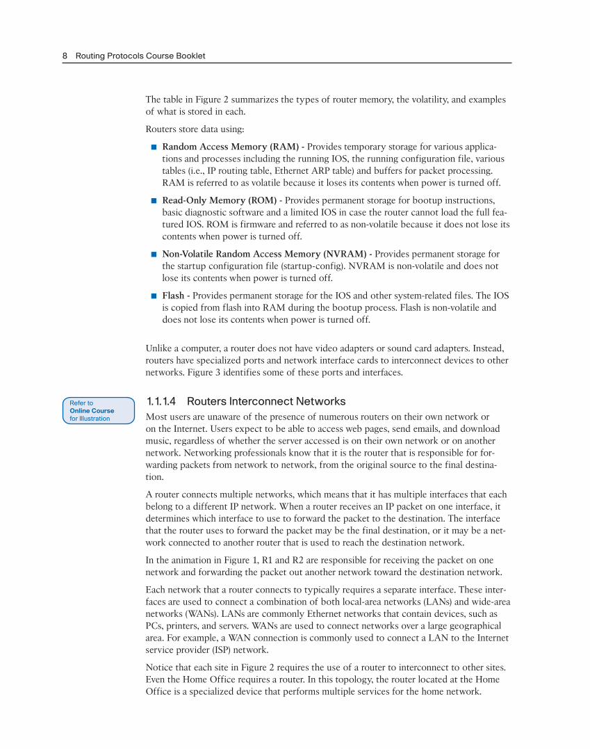
The table in Figure 2 summarizes the types of router memory, the volatility, and examples of what is stored in each.
Routers store data using:
■ Random Access Memory (RAM) - Provides temporary storage for various applica-tions and processes including the running IOS, the running configuration file, various tables (i.e., IP routing table, Ethernet ARP table) and buffers for packet processing. RAM is referred to as volatile because it loses its contents when power is turned off.
■ Read-Only Memory (ROM) - Provides permanent storage for bootup instructions, basic diagnostic software and a limited IOS in case the router cannot load the full fea-tured IOS. ROM is firmware and referred to as non-volatile because it does not lose its contents when power is turned off.
■ Non-Volatile Random Access Memory (NVRAM) - Provides permanent storage for the startup configuration file (startup-config). NVRAM is non-volatile and does not lose its contents when power is turned off.
■ Flash - Provides permanent storage for the IOS and other system-related files. The IOS is copied from flash into RAM during the bootup process. Flash is non-volatile and does not lose its contents when power is turned off.
Unlike a computer, a router does not have video adapters or sound card adapters. Instead, routers have specialized ports and network interface cards to interconnect devices to other networks. Figure 3 identifies some of these ports and interfaces.
1.1.1.4 Routers Interconnect NetworksMost users are unaware of the presence of numerous routers on their own network or on the Internet. Users expect to be able to access web pages, send emails, and download music, regardless of whether the server accessed is on their own network or on another network. Networking professionals know that it is the router that is responsible for for-warding packets from network to network, from the original source to the final destina-tion.
A router connects multiple networks, which means that it has multiple interfaces that each belong to a different IP network. When a router receives an IP packet on one interface, it determines which interface to use to forward the packet to the destination. The interface that the router uses to forward the packet may be the final destination, or it may be a net-work connected to another router that is used to reach the destination network.
In the animation in Figure 1, R1 and R2 are responsible for receiving the packet on one network and forwarding the packet out another network toward the destination network.
Each network that a router connects to typically requires a separate interface. These inter-faces are used to connect a combination of both local-area networks (LANs) and wide-area networks (WANs). LANs are commonly Ethernet networks that contain devices, such as PCs, printers, and servers. WANs are used to connect networks over a large geographical area. For example, a WAN connection is commonly used to connect a LAN to the Internet service provider (ISP) network.
Notice that each site in Figure 2 requires the use of a router to interconnect to other sites. Even the Home Office requires a router. In this topology, the router located at the Home Office is a specialized device that performs multiple services for the home network.

Chapter 1: Routing Concepts 9
1.1.1.5 Routers Choose Best PathsThe primary functions of a router are to:
■ Determine the best path to send packets
■ Forward packets toward their destination
The router uses its routing table to determine the best path to use to forward a packet. When the router receives a packet, it examines the destination address of the packet and uses the routing table to search for the best path to that network. The routing table also includes the interface to be used to forward packets for each known network. When a match is found, the router encapsulates the packet into the data link frame of the outgoing or exit interface, and the packet is forwarded toward its destination.
It is possible for a router to receive a packet that is encapsulated in one type of data link frame, and to forward the packet out of an interface that uses a different type of data link frame. For example, a router may receive a packet on an Ethernet interface, but must forward the packet out of an interface configured with the Point-to-Point Protocol (PPP). The data link encapsulation depends on the type of interface on the router and the type of medium to which it connects. The different data link technologies that a router can con-nect to include Ethernet, PPP, Frame Relay, DSL, cable, and wireless (802.11, Bluetooth).
The animation in the figure follows a packet from the source PC to the destination PC. Notice that it is the responsibility of the router to find the destination network in its routing table and forward the packet on toward its destination. In this example, router R1 receives the packet encapsulated in an Ethernet frame. After de-encapsulating the packet, R1 uses the destination IP address of the packet to search its routing table for a match-ing network address. After a destination network address is found in the routing table, R1 encapsulates the packet inside a PPP frame and forwards the packet to R2. A similar pro-cess is performed by R2.
Note Routers use static routes and dynamic routing protocols to learn about remote net-works and build their routing tables.
1.1.1.6 Packet Forwarding MechanismsRouters support three packet-forwarding mechanisms:
■ Process switching - An older packet forwarding mechanism still available for Cisco routers. When a packet arrives on an interface, it is forwarded to the control plane where the CPU matches the destination address with an entry in its routing table, and then determines the exit interface and forwards the packet. It is important to under-stand that the router does this for every packet, even if the destination is the same for a stream of packets. This process-switching mechanism is very slow and rarely imple-mented in modern networks.
■ Fast switching - This is a common packet forwarding mechanism which uses a fast-switching cache to store next-hop information. When a packet arrives on an interface, it is forwarded to the control plane where the CPU searches for a match in the fast-switching cache. If it is not there, it is process-switched and forwarded to the exit interface. The flow information for the packet is also stored in the fast-switching cache.
10 Routing Protocols Course Booklet
If another packet going to the same destination arrives on an interface, the next-hop information in the cache is re-used without CPU intervention.
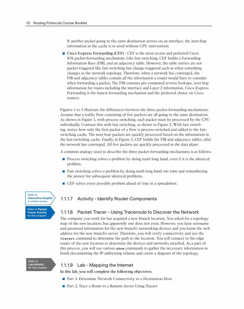
■ Cisco Express Forwarding (CEF) - CEF is the most recent and preferred Cisco IOS packet-forwarding mechanism. Like fast switching, CEF builds a Forwarding Information Base (FIB), and an adjacency table. However, the table entries are not packet-triggered like fast switching but change-triggered such as when something changes in the network topology. Therefore, when a network has converged, the FIB and adjacency tables contain all the information a router would have to consider when forwarding a packet. The FIB contains pre-computed reverse lookups, next hop information for routes including the interface and Layer 2 information. Cisco Express Forwarding is the fastest forwarding mechanism and the preferred choice on Cisco routers.
Figures 1 to 3 illustrate the differences between the three packet-forwarding mechanisms. Assume that a traffic flow consisting of five packets are all going to the same destination. As shown in Figure 1, with process switching, each packet must be processed by the CPU individually. Contrast this with fast switching, as shown in Figure 2. With fast switch-ing, notice how only the first packet of a flow is process-switched and added to the fast-switching cache. The next four packets are quickly processed based on the information in the fast-switching cache. Finally, in Figure 3, CEF builds the FIB and adjacency tables, after the network has converged. All five packets are quickly processed in the data plane.
A common analogy used to describe the three packet-forwarding mechanisms is as follows:
■ Process switching solves a problem by doing math long hand, even if it is the identical problem.
■ Fast switching solves a problem by doing math long hand one time and remembering the answer for subsequent identical problems.
■ CEF solves every possible problem ahead of time in a spreadsheet.
1.1.1.7 Activity - Identify Router Components
1.1.1.8 Packet Tracer - Using Traceroute to Discover the NetworkThe company you work for has acquired a new branch location. You asked for a topology map of the new location, but apparently one does not exist. However, you have username and password information for the new branch’s networking devices and you know the web address for the new branch’s server. Therefore, you will verify connectivity and use the tracert command to determine the path to the location. You will connect to the edge router of the new location to determine the devices and networks attached. As a part of this process, you will use various show commands to gather the necessary information to finish documenting the IP addressing scheme and create a diagram of the topology.
1.1.1.9 Lab - Mapping the InternetIn this lab, you will complete the following objectives:
■ Part 1: Determine Network Connectivity to a Destination Host
■ Part 2: Trace a Route to a Remote Server Using Tracert
Refer toInteractive Graphicin online course.
Refer to PacketTracer Activityfor this chapter
Refer toLab Activityfor this chapter
Chapter 1: Routing Concepts 11
1.1.2 Connect Devices
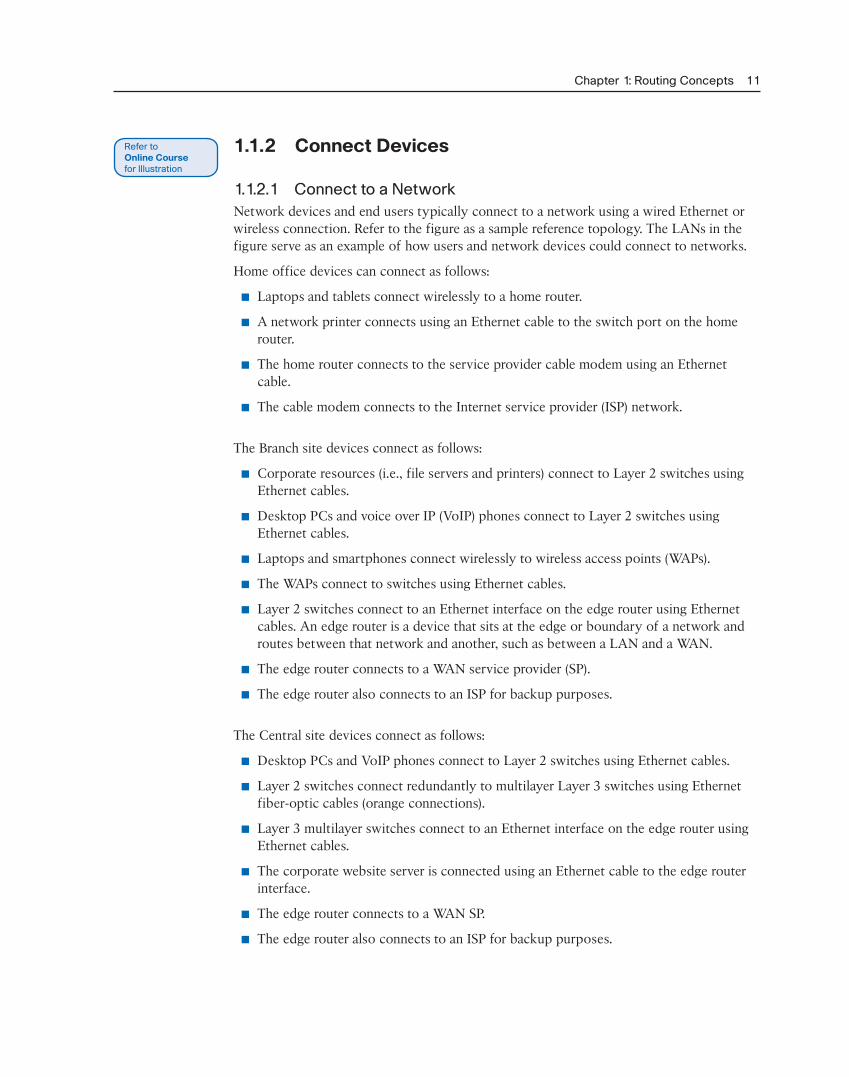
1.1.2.1 Connect to a NetworkNetwork devices and end users typically connect to a network using a wired Ethernet or wireless connection. Refer to the figure as a sample reference topology. The LANs in the figure serve as an example of how users and network devices could connect to networks.
Home office devices can connect as follows:
■ Laptops and tablets connect wirelessly to a home router.
■ A network printer connects using an Ethernet cable to the switch port on the home router.
■ The home router connects to the service provider cable modem using an Ethernet cable.
■ The cable modem connects to the Internet service provider (ISP) network.
The Branch site devices connect as follows:
■ Corporate resources (i.e., file servers and printers) connect to Layer 2 switches using Ethernet cables.
■ Desktop PCs and voice over IP (VoIP) phones connect to Layer 2 switches using Ethernet cables.
■ Laptops and smartphones connect wirelessly to wireless access points (WAPs).
■ The WAPs connect to switches using Ethernet cables.
■ Layer 2 switches connect to an Ethernet interface on the edge router using Ethernet cables. An edge router is a device that sits at the edge or boundary of a network and routes between that network and another, such as between a LAN and a WAN.
■ The edge router connects to a WAN service provider (SP).
■ The edge router also connects to an ISP for backup purposes.
The Central site devices connect as follows:
■ Desktop PCs and VoIP phones connect to Layer 2 switches using Ethernet cables.
■ Layer 2 switches connect redundantly to multilayer Layer 3 switches using Ethernet fiber-optic cables (orange connections).
■ Layer 3 multilayer switches connect to an Ethernet interface on the edge router using Ethernet cables.
■ The corporate website server is connected using an Ethernet cable to the edge router interface.
■ The edge router connects to a WAN SP.
■ The edge router also connects to an ISP for backup purposes.
12 Routing Protocols Course Booklet
In the Branch and Central LANs, hosts are connected either directly or indirectly (via WAPs) to the network infrastructure using a Layer 2 switch.
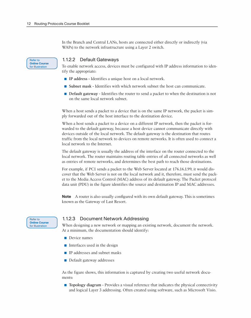
1.1.2.2 Default GatewaysTo enable network access, devices must be configured with IP address information to iden-tify the appropriate:
■ IP address - Identifies a unique host on a local network.
■ Subnet mask - Identifies with which network subnet the host can communicate.
■ Default gateway - Identifies the router to send a packet to when the destination is not on the same local network subnet.
When a host sends a packet to a device that is on the same IP network, the packet is sim-ply forwarded out of the host interface to the destination device.
When a host sends a packet to a device on a different IP network, then the packet is for-warded to the default gateway, because a host device cannot communicate directly with devices outside of the local network. The default gateway is the destination that routes traffic from the local network to devices on remote networks. It is often used to connect a local network to the Internet.
The default gateway is usually the address of the interface on the router connected to the local network. The router maintains routing table entries of all connected networks as well as entries of remote networks, and determines the best path to reach those destinations.
For example, if PC1 sends a packet to the Web Server located at 176.16.1.99, it would dis-cover that the Web Server is not on the local network and it, therefore, must send the pack-et to the Media Access Control (MAC) address of its default gateway. The Packet protocol data unit (PDU) in the figure identifies the source and destination IP and MAC addresses.
Note A router is also usually configured with its own default gateway. This is sometimes known as the Gateway of Last Resort.
1.1.2.3 Document Network AddressingWhen designing a new network or mapping an existing network, document the network. At a minimum, the documentation should identify:
■ Device names
■ Interfaces used in the design
■ IP addresses and subnet masks
■ Default gateway addresses
As the figure shows, this information is captured by creating two useful network docu-ments:
■ Topology diagram - Provides a visual reference that indicates the physical connectivity and logical Layer 3 addressing. Often created using software, such as Microsoft Visio.
Chapter 1: Routing Concepts 13
■ An addressing table - A table that captures device names, interfaces, IPv4 addresses, subnet masks, and default gateway addresses.
1.1.2.4 Enable IP on a HostA host can be assigned IP address information either:
■ Statically - The host is manually assigned the correct IP address, subnet mask, and default gateway. The DNS server IP address can also be configured.
■ Dynamically - IP address information is provided by a server using the Dynamic Host Configuration Protocol (DHCP). The DHCP server provides a valid IP address, subnet mask, and default gateway for end devices. Other information may be provided by the server.
Figure 1 and Figure 2 provide static and dynamic IPv4 address configuration examples.
Statically assigned addresses are commonly used to identify specific network resources, such as network servers and printers. They can also be used in smaller networks with few hosts. However, most host devices acquire their IPv4 address information by accessing a DHCP server. In large enterprises, dedicated DHCP servers providing services to many LANs are implemented. In a smaller branch or small office setting, DHCP services can be provided by a Cisco Catalyst switch or a Cisco ISR.
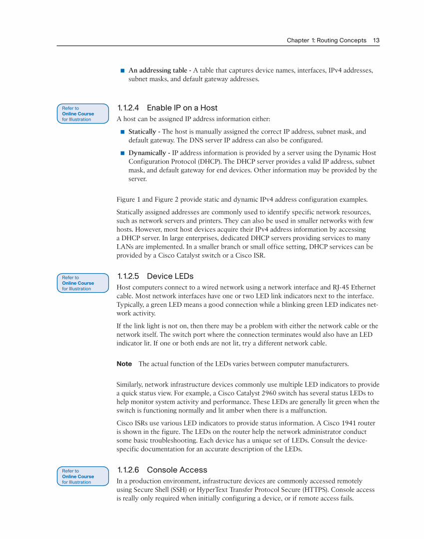
1.1.2.5 Device LEDsHost computers connect to a wired network using a network interface and RJ-45 Ethernet cable. Most network interfaces have one or two LED link indicators next to the interface. Typically, a green LED means a good connection while a blinking green LED indicates net-work activity.
If the link light is not on, then there may be a problem with either the network cable or the network itself. The switch port where the connection terminates would also have an LED indicator lit. If one or both ends are not lit, try a different network cable.
Note The actual function of the LEDs varies between computer manufacturers.
Similarly, network infrastructure devices commonly use multiple LED indicators to provide a quick status view. For example, a Cisco Catalyst 2960 switch has several status LEDs to help monitor system activity and performance. These LEDs are generally lit green when the switch is functioning normally and lit amber when there is a malfunction.
Cisco ISRs use various LED indicators to provide status information. A Cisco 1941 router is shown in the figure. The LEDs on the router help the network administrator conduct some basic troubleshooting. Each device has a unique set of LEDs. Consult the device-specific documentation for an accurate description of the LEDs.
1.1.2.6 Console AccessIn a production environment, infrastructure devices are commonly accessed remotely using Secure Shell (SSH) or HyperText Transfer Protocol Secure (HTTPS). Console access is really only required when initially configuring a device, or if remote access fails.
14 Routing Protocols Course Booklet
Console access requires:
■ Console cable – RJ-45-to-DB-9 console cable
■ Terminal emulation software – Tera Term, PuTTY, HyperTerminal
The cable is connected between the serial port of the host and the console port on the device. Most computers and notebooks no longer include built-in serial ports. If the host does not have a serial port, the USB port can be used to establish a console connection. A special USB-to-RS-232 compatible serial port adapter is required when using the USB port.
The Cisco ISR G2 supports a USB serial console connection. To establish connectivity, a USB Type-A to USB Type-B (mini-B USB) is required, as well as an operating system device driver. This device driver is available from http://www.cisco.com. Although these routers have two console ports, only one console port can be active at a time. When a cable is plugged into the USB console port, the RJ-45 port becomes inactive. When the USB cable is removed from the USB port, the RJ-45 port becomes active.
The table in Figure 1 summarizes the console connection requirements. Figure 2 displays the various ports and cables required.
1.1.2.7 Enable IP on a SwitchNetwork infrastructure devices require IP addresses to enable remote management. Using the device IP address, the network administrator can remotely connect to the device using Telnet, SSH, HTTP, or HTTPS.
A switch does not have a dedicated interface to which an IP address can be assigned. Instead, the IP address information is configured on a virtual interface called a switched virtual interface (SVI).
For example, in Figure 1, the SVI on the Layer 2 switch S1 is assigned the IP address 192.168.10.2/24 and a default gateway of the router located at 192.168.10.1.
Use the Syntax Checker in Figure 2 to configure the Layer 2 switch S2.
1.1.2.8 Activity - Document an Addressing Scheme
1.1.2.9 Packet Tracer - Documenting the NetworkBackground/Scenario
Your job is to document the addressing scheme and connections used in the Central por-tion of the network. You will need to use a variety of commands to gather the required information.
1.1.3 Basic Settings on a router
1.1.3.1 Configure Basic Router SettingsCisco routers and Cisco switches have many similarities. They support a similar modal operating system, similar command structures, and many of the same commands. In addi-tion, both devices have similar initial configuration steps.
Refer toInteractive Graphicin online course.
Refer to PacketTracer Activityfor this chapter
Chapter 1: Routing Concepts 15
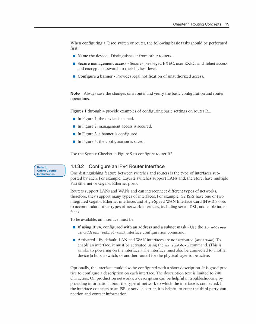
When configuring a Cisco switch or router, the following basic tasks should be performed first:
■ Name the device - Distinguishes it from other routers.
■ Secure management access - Secures privileged EXEC, user EXEC, and Telnet access, and encrypts passwords to their highest level.
■ Configure a banner - Provides legal notification of unauthorized access.
Note Always save the changes on a router and verify the basic configuration and router operations.
Figures 1 through 4 provide examples of configuring basic settings on router R1:
■ In Figure 1, the device is named.
■ In Figure 2, management access is secured.
■ In Figure 3, a banner is configured.
■ In Figure 4, the configuration is saved.
Use the Syntax Checker in Figure 5 to configure router R2.
1.1.3.2 Configure an IPv4 Router InterfaceOne distinguishing feature between switches and routers is the type of interfaces sup-ported by each. For example, Layer 2 switches support LANs and, therefore, have multiple FastEthernet or Gigabit Ethernet ports.
Routers support LANs and WANs and can interconnect different types of networks; therefore, they support many types of interfaces. For example, G2 ISRs have one or two integrated Gigabit Ethernet interfaces and High-Speed WAN Interface Card (HWIC) slots to accommodate other types of network interfaces, including serial, DSL, and cable inter-faces.
To be available, an interface must be:
■ If using IPv4, configured with an address and a subnet mask - Use the ip address ip-address subnet-mask interface configuration command.
■ Activated - By default, LAN and WAN interfaces are not activated (shutdown). To enable an interface, it must be activated using the no shutdown command. (This is similar to powering on the interface.) The interface must also be connected to another device (a hub, a switch, or another router) for the physical layer to be active.
Optionally, the interface could also be configured with a short description. It is good prac-tice to configure a description on each interface. The description text is limited to 240 characters. On production networks, a description can be helpful in troubleshooting by providing information about the type of network to which the interface is connected. If the interface connects to an ISP or service carrier, it is helpful to enter the third party con-nection and contact information.

16 Routing Protocols Course Booklet
Depending on the type of interface, additional parameters may be required. For example, in the lab environment, the serial interface connecting to the serial cable end labeled DCE must be configured with the clock rate command.
Note Accidentally using the clock rate command on a DTE interface generates a %Er-ror: This command applies only to DCE interface message.
Figures 1 through 3 provide examples of configuring the router interfaces of R1.
Use the Syntax Checker in Figure 4 to configure router R2.
1.1.3.3 Configure an IPv6 Router InterfaceConfiguring an IPv6 interface is similar to configuring an interface for IPv4. Most IPv6 configuration and verification commands in the Cisco IOS are very similar to their IPv4 counterparts. In many cases, the only difference uses ipv6 in place of ip in commands.
An IPv6 interface must be:
■ Configured with IPv6 address and subnet mask - Use the ipv6 address ipv6-address/prefix-length [link-local | eui-64] interface configuration com-mand.
■ Activated - The interface must be activated using the no shutdown command.
Note An interface can generate its own IPv6 link-local address without having a global unicast address by using the ipv6 enable interface configuration command.
Unlike IPv4, IPv6 interfaces will typically have more than one IPv6 address. At a minimum, an IPv6 device must have an IPv6 link-local address but will most likely also have an IPv6 global unicast address. IPv6 also supports the ability for an interface to have multiple IPv6 global unicast addresses from the same subnet. The following commands can be used to statically create a global unicast or link-local IPv6 address:
■ ipv6 address ipv6-address / prefix-length - Creates a global unicast IPv6 address as specified.
■ ipv6 address ipv6-address / prefix-length eui-64 - Configures a global uni-cast IPv6 address with an interface identifier (ID) in the low-order 64 bits of the IPv6 address using the EUI-64 process.
■ ipv6 address ipv6-address / prefix-length link-local - Configures a static link-local address on the interface that is used instead of the link-local address that is automatically configured when the global unicast IPv6 address is assigned to the inter-face or enabled using the ipv6 enable interface command. Recall, the ipv6 enable interface command is used to automatically create an IPv6 link-local address whether or not an IPv6 global unicast address has been assigned.
Chapter 1: Routing Concepts 17
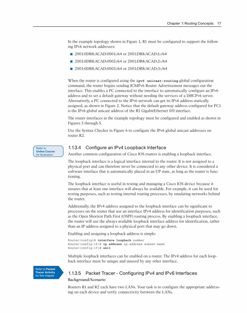
In the example topology shown in Figure 1, R1 must be configured to support the follow-ing IPv6 network addresses:
■ 2001:0DB8:ACAD:0001:/64 or 2001:DB8:ACAD:1::/64
■ 2001:0DB8:ACAD:0002:/64 or 2001:DB8:ACAD:2::/64
■ 2001:0DB8:ACAD:0003:/64 or 2001:DB8:ACAD:3::/64
When the router is configured using the ipv6 unicast-routing global configuration command, the router begins sending ICMPv6 Router Advertisement messages out the interface. This enables a PC connected to the interface to automatically configure an IPv6 address and to set a default gateway without needing the services of a DHCPv6 server. Alternatively, a PC connected to the IPv6 network can get its IPv6 address statically assigned, as shown in Figure 2. Notice that the default gateway address configured for PC1 is the IPv6 global unicast address of the R1 GigabitEthernet 0/0 interface.
The router interfaces in the example topology must be configured and enabled as shown in Figures 3 through 5.
Use the Syntax Checker in Figure 6 to configure the IPv6 global unicast addresses on router R2.
1.1.3.4 Configure an IPv4 Loopback InterfaceAnother common configuration of Cisco IOS routers is enabling a loopback interface.
The loopback interface is a logical interface internal to the router. It is not assigned to a physical port and can therefore never be connected to any other device. It is considered a software interface that is automatically placed in an UP state, as long as the router is func-tioning.
The loopback interface is useful in testing and managing a Cisco IOS device because it ensures that at least one interface will always be available. For example, it can be used for testing purposes, such as testing internal routing processes, by emulating networks behind the router.
Additionally, the IPv4 address assigned to the loopback interface can be significant to processes on the router that use an interface IPv4 address for identification purposes, such as the Open Shortest Path First (OSPF) routing process. By enabling a loopback interface, the router will use the always available loopback interface address for identification, rather than an IP address assigned to a physical port that may go down.
Enabling and assigning a loopback address is simple:Router(config)# interface loopback numberRouter(config-if)# ip address ip-address subnet-maskRouter(config-if)# exit
Multiple loopback interfaces can be enabled on a router. The IPv4 address for each loop-back interface must be unique and unused by any other interface.
1.1.3.5 Packet Tracer - Configuring IPv4 and IPv6 InterfacesBackground/Scenario
Routers R1 and R2 each have two LANs. Your task is to configure the appropriate address-ing on each device and verify connectivity between the LANs.
Refer to PacketTracer Activityfor this chapter

18 Routing Protocols Course Booklet
1.1.4 Verify Connectivity of Directly Connected Networks
1.1.4.1 Verify Interface SettingsThere are several show commands that can be used to verify the operation and configura-tion of an interface. The following three commands are especially useful to quickly iden-tify an interface status:
■ show ip interface brief - Displays a summary for all interfaces including the IPv4 address of the interface and current operational status.
■ show ip route - Displays the contents of the IPv4 routing table stored in RAM. In Cisco IOS 15, active interfaces should appear in the routing table with two related entries identified by the code ‘C’ (Connected) or ‘L’ (Local). In previous IOS versions, only a single entry with the code ‘C’ will appear.
■ show running-config interface interface-id - Displays the commands config-ured on the specified interface.
Figure 1 displays the output of the show ip interface brief command. The output reveals that the LAN interfaces and the WAN link are all activated and operational as indi-cated by the Status of “up” and Protocol of “up”. A different output would indicate a prob-lem with either the configuration or the cabling.
Note In Figure 1, the Embedded-Service-Engine0/0 interface is displayed because Cisco ISRs G2 have dual core CPUs on the motherboard. The Embedded-Service-Engine0/0 inter-face is outside the scope of this course.
Figure 2 displays the output of the show ip route command. Notice the three directly connected network entries and the three local host route interface entries. A local host route has an administrative distance of 0. It also has a /32 mask for IPv4, and a /128 mask for IPv6. The local host route is for routes on the router owning the IP address. It is used to allow the router to process packets destined to that IP.
Figure 3 displays the output of the show running-config interface command. The output displays the current commands configured on the specified interface.
The following two commands are used to gather more detailed interface information:
■ show interfaces - Displays interface information and packet flow count for all inter-faces on the device.
■ show ip interface - Displays the IPv4 related information for all interfaces on a router.
Use the Syntax Checker in Figures 4 and 5 to verify the interfaces on R1.
1.1.4.2 Verify IPv6 Interface SettingsThe commands to verify the IPv6 interface configuration are similar to the commands used for IPv4.

Chapter 1: Routing Concepts 19
The show ipv6 interface brief command in Figure 1 displays a summary for each of the interfaces. The [up/up] output on the same line as the interface name indicates the Layer 1/Layer 2 interface state. This is the same as the Status and Protocol columns in the equivalent IPv4 command.
The output displays two configured IPv6 addresses per interface. One address is the IPv6 global unicast address that was manually entered. The other address, which begins with FE80, is the link-local unicast address for the interface. A link-local address is automatically added to an interface whenever a global unicast address is assigned. An IPv6 network inter-face is required to have a link-local address, but not necessarily a global unicast address.
The show ipv6 interface gigabitethernet 0/0 command output shown in Figure 2 displays the interface status and all of the IPv6 addresses belonging to the interface. Along with the link local address and global unicast address, the output includes the multicast addresses assigned to the interface, beginning with prefix FF02.
The show ipv6 route command shown in Figure 3 can be used to verify that IPv6 net-works and specific IPv6 interface addresses have been installed in the IPv6 routing table. The show ipv6 route command will only display IPv6 networks, not IPv4 networks.
Within the routing table, a ‘C’ next to a route indicates that this is a directly connected network. When the router interface is configured with a global unicast address and is in the “up/up” state, the IPv6 prefix and prefix length is added to the IPv6 routing table as a con-nected route.
The IPv6 global unicast address configured on the interface is also installed in the routing table as a local route. The local route has a /128 prefix. Local routes are used by the rout-ing table to efficiently process packets with the interface address of the router as the desti-nation.
The ping command for IPv6 is identical to the command used with IPv4 except that an IPv6 address is used. As shown in Figure 4, the ping command is used to verify Layer 3 connectivity between R1 and PC1.
Other useful IPv6 verification commands include:
■ show interface
■ show ipv6 routers
1.1.4.3 Filter Show Command OutputCommands that generate multiple screens of output are, by default, paused after 24 lines. At the end of the paused output, the --More-- text displays. Pressing Enter displays the next line and pressing the spacebar displays the next set of lines. Use the terminal length number command to specify the number of lines to be displayed. A value of 0 (zero) prevents the router from pausing between screens of output.
Another very useful feature that improves the user experience in the command-line inter-face (CLI) is the filtering of show output. Filtering commands can be used to display spe-cific sections of output. To enable the filtering command, enter a pipe (|) character after the show command and then enter a filtering parameter and a filtering expression.

20 Routing Protocols Course Booklet
The filtering parameters that can be configured after the pipe include:
■ section - Shows entire section that starts with the filtering expression
■ include - Includes all output lines that match the filtering expression
■ exclude - Excludes all output lines that match the filtering expression
■ begin - Shows all the output lines from a certain point, starting with the line that matches the filtering expression
Note Output filters can be used in combination with any show command.
Figures 1 to 4 provide examples of the various output filters.
Use the Syntax Checker in Figure 5 to filter output.
1.1.4.4 Command History FeatureThe command history feature is useful, because it temporarily stores the list of executed commands to be recalled.
To recall commands in the history buffer, press Ctrl+P or the Up Arrow key. The com-mand output begins with the most recent command. Repeat the key sequence to recall successively older commands. To return to more recent commands in the history buffer, press Ctrl+N or the Down Arrow key. Repeat the key sequence to recall successively more recent commands.
By default, command history is enabled and the system captures the last 10 command lines in its history buffer. Use the show history privileged EXEC command to display the con-tents of the buffer.
It is also practical to increase the number of command lines that the history buffer records during the current terminal session only. Use the terminal history size user EXEC command to increase or decrease the size of the buffer.
Figure 1 displays a sample of the terminal history size and show history com-mands.
Use the Syntax Checker in Figure 2 to practice the two EXEC commands.
1.1.4.5 Packet Tracer - Configuring and Verifying a Small NetworkBackground/Scenario
In this activity, you will configure a router with basic settings including IP addressing. You will also configure a switch for remote management and configure the PCs. After you have successfully verified connectivity, you will use show commands to gather information about the network.
1.1.4.6 Lab - Configuring Basic Router Settings with IOS CLIIn this lab, you will complete the following objectives:
■ Part 1: Set Up the Topology and Initialize Devices
■ Part 2: Configure Devices and Verify Connectivity
Refer to PacketTracer Activityfor this chapter
Refer toLab Activityfor this chapter
Chapter 1: Routing Concepts 21
■ Part 3: Display Router Information
■ Part 4: Configure IPv6 and Verify Connectivity
1.1.4.7 Lab - Configuring Basic Router Settings with CCPIn this lab, you will complete the following objectives:
■ Part 1: Set Up the Topology and Initialize Devices
■ Part 2: Configure Devices and Verify Connectivity
■ Part 3: Configure Router to Allow CCP Access
■ Part 4: (Optional) Install and Setup CCP on PC-A
■ Part 5: Configure R1 Settings Using CCP
■ Part 6: Use CCP Utilities
1.2 routing Decisions
1.2.1 Switching packets Between Networks
1.2.1.1 Router Switching FunctionA primary function of a router is to forward packets toward their destination. This is accomplished by using a switching function, which is the process used by a router to accept a packet on one interface and forward it out of another interface. A key responsibil-ity of the switching function is to encapsulate packets in the appropriate data link frame type for the outgoing data link.
Note In this context, the term “switching” literally means moving packets from source to destination and should not be confused with the function of a Layer 2 switch.
After the router has determined the exit interface using the path determination function, the router must encapsulate the packet into the data link frame of the outgoing interface.
What does a router do with a packet received from one network and destined for another network? The router performs the following three major steps:
Step 1. De-encapsulates the Layer 3 packet by removing the Layer 2 frame header and trailer.
Step 2. Examines the destination IP address of the IP packet to find the best path in the routing table.
Step 3. If the router finds a path to the destination, it encapsulates the Layer 3 packet into a new Layer 2 frame and forwards the frame out the exit interface.
As shown in the figure, devices have Layer 3 IPv4 addresses and Ethernet interfaces have Layer 2 data link addresses. For example, PC1 is configured with IPv4 address 192.168.1.10
Refer toLab Activityfor this chapter

22 Routing Protocols Course Booklet
and an example MAC address of 0A-10. As a packet travels from the source device to the final destination device, the Layer 3 IP addresses do not change. However, the Layer 2 data link addresses change at every hop as the packet is de-encapsulated and re-encapsulated in a new frame by each router. It is very likely that the packet is encapsulated in a differ-ent type of Layer 2 frame than the one in which it was received. For example, an Ethernet encapsulated frame might be received by the router on a FastEthernet interface, and then processed to be forwarded out of a serial interface as a Point-to-Point Protocol (PPP) encapsulated frame.
1.2.1.2 Send a PacketIn the animation in the figure, PC1 is sending a packet to PC2. PC1 must determine if the destination IPv4 address is on the same network. PC1 determines its own subnet by doing an AND operation on its own IPv4 address and subnet mask. This produces the network address that PC1 belongs to. Next, PC1 does this same AND operation using the packet destination IPv4 address and the PC1 subnet mask.
If the destination network address is the same network as PC1, then PC1 does not use the default gateway. Instead, PC1 refers to its ARP cache for the MAC address of the device with that destination IPv4 address. If the MAC address is not in the cache, then PC1 gener-ates an ARP request to acquire the address to complete the packet and send it to the desti-nation. If the destination network address is on a different network, then PC1 forwards the packet to its default gateway.
To determine the MAC address of the default gateway, PC1 checks its ARP table for the IPv4 address of the default gateway and its associated MAC address.
If an ARP entry does not exist in the ARP table for the default gateway, PC1 sends an ARP request. Router R1 sends back an ARP reply. PC1 can then forward the packet to the MAC address of the default gateway, the Fa0/0 interface of router R1.
A similar process is used for IPv6 packets. Instead of the ARP process, IPv6 address reso-lution uses ICMPv6 Neighbor Solicitation and Neighbor Advertisement messages. IPv6-to-MAC address mapping are kept in a table similar to the ARP cache, called the neighbor cache.
1.2.1.3 Forward to the Next HopThe following processes take place when R1 receives the Ethernet frame from PC1:
1. R1 examines the destination MAC address, which matches the MAC address of the receiving interface, FastEthernet 0/0. R1, therefore, copies the frame into its buffer.
2. R1 identifies the Ethernet Type field as 0x800, which means that the Ethernet frame contains an IPv4 packet in the data portion of the frame.
3. R1 de-encapsulates the Ethernet frame.
4. Because the destination IPv4 address of the packet does not match any of the directly connected networks of R1, R1 consults its routing table to route this packet. R1 searches the routing table for a network address that would include the destination IPv4 address of the packet as a host address within that network. In this example, the routing table has a route for the 192.168.4.0/24 network. The destination IPv4 address of the packet is 192.168.4.10, which is a host IPv4 address on that network.
Chapter 1: Routing Concepts 23
The route that R1 finds to the 192.168.4.0/24 network has a next-hop IPv4 address of 192.168.2.2 and an exit interface of FastEthernet 0/1. This means that the IPv4 packet is encapsulated in a new Ethernet frame with the destination MAC address of the IPv4 address of the next-hop router.
Because the exit interface is on an Ethernet network, R1 must resolve the next-hop IPv4 address with a destination MAC address using ARP:
1. R1 looks up the next-hop IPv4 address of 192.168.2.2 in its ARP cache. If the entry is not in the ARP cache, R1 would send an ARP request out of its FastEthernet 0/1 inter-face and R2 would send back an ARP reply. R1 would then update its ARP cache with an entry for 192.168.2.2 and the associated MAC address.
2. The IPv4 packet is now encapsulated into a new Ethernet frame and forwarded out the FastEthernet 0/1 interface of R1.
The animation in the figure illustrates how R1 forwards the packet to R2.
1.2.1.4 Packet RoutingThe following processes take place when R2 receives the frame on its Fa0/0 interface:
1. R2 examines the destination MAC address, which matches the MAC address of the receiving interface, FastEthernet 0/0. R2, therefore, copies the frame into its buffer.
2. R2 identifies the Ethernet Type field as 0x800, which means that the Ethernet frame contains an IPv4 packet in the data portion of the frame.
3. R2 de-encapsulates the Ethernet frame.
4. Because the destination IPv4 address of the packet does not match any of the inter-face addresses of R2, R2 consults its routing table to route this packet. R2 searches the routing table for the destination IPv4 address of the packet using the same process R1 used.
The routing table of R2 has a route to the 192.168.4.0/24 network, with a next-hop IPv4 address of 192.168.3.2 and an exit interface of Serial 0/0/0. Because the exit inter-face is not an Ethernet network, R2 does not have to resolve the next-hop IPv4 address with a destination MAC address.
5. The IPv4 packet is now encapsulated into a new data link frame and sent out the Serial 0/0/0 exit interface.
When the interface is a point-to-point (P2P) serial connection, the router encapsulates the IPv4 packet into the proper data link frame format used by the exit interface (HDLC, PPP, etc.). Because there are no MAC addresses on serial interfaces, R2 sets the data link desti-nation address to an equivalent of a broadcast.
The animation in the figure illustrates how R2 forwards the packet to R3.
1.2.1.5 Reach the DestinationThe following processes take place when the frame arrives at R3:
1. R3 copies the data link PPP frame into its buffer.
2. R3 de-encapsulates the data link PPP frame.

24 Routing Protocols Course Booklet
3. R3 searches the routing table for the destination IPv4 address of the packet. The routing table has a route to a directly connected network on R3. This means that the packet can be sent directly to the destination device and does not need to be sent to another router.
Because the exit interface is a directly connected Ethernet network, R3 must resolve the destination IPv4 address of the packet with a destination MAC address:
1. R3 searches for the destination IPv4 address of the packet in its Address Resolution Protocol (ARP) cache. If the entry is not in the ARP cache, R3 sends an ARP request out of its FastEthernet 0/0 interface. PC2 sends back an ARP reply with its MAC address. R3 then updates its ARP cache with an entry for 192.168.4.10 and the MAC address that is returned in the ARP reply.
2. The IPv4 packet is encapsulated into a new Ethernet data link frame and sent out the FastEthernet 0/0 interface of R3.
3. When PC2 receives the frame, it examines the destination MAC address, which match-es the MAC address of the receiving interface, its Ethernet network interface card (NIC). PC2, therefore, copies the rest of the frame into its buffer.
4. PC2 identifies the Ethernet Type field as 0x800, which means that the Ethernet frame contains an IPv4 packet in the data portion of the frame.
5. PC2 de-encapsulates the Ethernet frame and passes the IPv4 packet to the IPv4 pro-cess of its operating system.
The animation in the figure illustrates how R3 forwards the packet to PC2.
1.2.1.6 Activity - Match Layer 2 and Layer 3 Addressing
1.2.2 path Determination
1.2.2.1 Routing DecisionsA primary function of a router is to determine the best path to use to send packets. To determine the best path, the router searches its routing table for a network address that matches the destination IP address of the packet.
The routing table search results in one of three path determinations:
■ Directly connected network - If the destination IP address of the packet belongs to a device on a network that is directly connected to one of the interfaces of the router, that packet is forwarded directly to the destination device. This means that the desti-nation IP address of the packet is a host address on the same network as the interface of the router.
■ Remote network - If the destination IP address of the packet belongs to a remote net-work, then the packet is forwarded to another router. Remote networks can only be reached by forwarding packets to another router.
■ No route determined - If the destination IP address of the packet does not belong to either a connected or remote network, the router determines if there is a Gateway of Last Resort available. A Gateway of Last Resort is set when a default route is config-ured on a router. If there is a default route, the packet is forwarded to the Gateway of Last Resort. If the router does not have a default route, then the packet is discarded. If
Refer toInteractive Graphicin online course.
Chapter 1: Routing Concepts 25
the packet is discarded, the router sends an ICMP unreachable message to the source IP address of the packet.
The logic flowchart in the figure illustrates the router packet forwarding decision process.
1.2.2.2 Best PathDetermining the best path involves the evaluation of multiple paths to the same destina-tion network and selecting the optimum or shortest path to reach that network. Whenever multiple paths to the same network exist, each path uses a different exit interface on the router to reach that network.
The best path is selected by a routing protocol based on the value or metric it uses to determine the distance to reach a network. A metric is the quantitative value used to mea-sure the distance to a given network. The best path to a network is the path with the low-est metric.
Dynamic routing protocols typically use their own rules and metrics to build and update routing tables. The routing algorithm generates a value, or a metric, for each path through the network. Metrics can be based on either a single characteristic or several characteristics of a path. Some routing protocols can base route selection on multiple metrics, combining them into a single metric.
The following lists some dynamic protocols and the metrics they use:
■ Routing Information Protocol (RIP) - Hop count
■ Open Shortest Path First (OSPF) - Cisco’s cost based on cumulative bandwidth from source to destination
■ Enhanced Interior Gateway Routing Protocol (EIGRP) - Bandwidth, delay, load, reli-ability
The animation in the figure highlights how the path may be different depending on the metric being used.
1.2.2.3 Load BalancingWhat happens if a routing table has two or more paths with identical metrics to the same destination network?
When a router has two or more paths to a destination with equal cost metrics, then the router forwards the packets using both paths equally. This is called equal cost load balanc-ing. The routing table contains the single destination network, but has multiple exit inter-faces, one for each equal cost path. The router forwards packets using the multiple exit interfaces listed in the routing table.
If configured correctly, load balancing can increase the effectiveness and performance of the network. Equal cost load balancing can be configured to use both dynamic routing protocols and static routes.
Note Only EIGRP supports unequal cost load balancing.
The animation in the figure provides an example of equal cost load balancing.

26 Routing Protocols Course Booklet
1.2.2.4 Administrative DistanceIt is possible for a router to be configured with multiple routing protocols and static routes. If this occurs, the routing table may have more than one route source for the same destination network. For example, if both RIP and EIGRP are configured on a router, both routing protocols may learn of the same destination network. However, each routing proto-col may decide on a different path to reach the destination based on that routing protocol’s metrics. RIP chooses a path based on hop count, whereas EIGRP chooses a path based on its composite metric. How does the router know which route to use?
Cisco IOS uses what is known as the administrative distance (AD) to determine the route to install into the IP routing table. The AD represents the “trustworthiness” of the route; the lower the AD, the more trustworthy the route source. For example, a static route has an AD of 1, whereas an EIGRP-discovered route has an AD of 90. Given two separate routes to the same destination, the router chooses the route with the lowest AD. When a router has the choice of a static route and an EIGRP route, the static route takes precedence. Similarly, a directly connected route with an AD of 0 takes precedence over a static route with an AD of 1.
The figure lists various routing protocols and their associated ADs.
1.2.2.5 Activity - Order the Steps in the Packet Forwarding Process
1.3 router Operation
1.3.1 analyze the routing table
1.3.1.1 The Routing TableThe routing table of a router stores information about:
■ Directly connected routes - These routes come from the active router interfaces. Routers add a directly connected route when an interface is configured with an IP address and is activated.
■ Remote routes - These are remote networks connected to other routers. Routes to these networks can either be statically configured or dynamically configured using dynamic routing protocols.
Specifically, a routing table is a data file in RAM that is used to store route information about directly connected and remote networks. The routing table contains network or next hop associations. These associations tell a router that a particular destination can be opti-mally reached by sending the packet to a specific router that represents the next hop on the way to the final destination. The next hop association can also be the outgoing or exit interface to the next destination.
The figure identifies the directly connected networks and remote networks of router R1.
Refer toInteractive Graphicin online course.
Chapter 1: Routing Concepts 27
1.3.1.2 Routing Table SourcesOn a Cisco IOS router, the show ip route command can be used to display the IPv4 routing table of a router. A router provides additional route information, including how the route was learned, how long the route has been in the table, and which specific interface to use to get to a predefined destination.
Entries in the routing table can be added as:
■ Local Route interfaces - Added when an interface is configured and active. This entry is only displayed in IOS 15 or newer for IPv4 routes and all IOS releases for IPv6 routes.
■ Directly connected interfaces - Added to the routing table when an interface is con-figured and active.
■ Static routes - Added when a route is manually configured and the exit interface is active.
■ Dynamic routing protocol - Added when routing protocols that dynamically learn about the network, such as EIGRP or OSPF, are implemented and networks are identi-fied.
The sources of the routing table entries are identified by a code. The code identifies how the route was learned. For instance, common codes include:
■ L - Identifies the address assigned to a router’s interface. This allows the router to effi-ciently determine when it receives a packet for the interface instead of being forward-ed.
■ C - Identifies a directly connected network.
■ S - Identifies a static route created to reach a specific network.
■ D - Identifies a dynamically learned network from another router using EIGRP.
■ O - Identifies a dynamically learned network from another router using the OSPF rout-ing protocol.
Note Other codes are beyond the scope of this chapter.
The figure shows the routing table of R1 in a simple network.
1.3.1.3 Remote Network Routing EntriesAs a network administrator, it is imperative to know how to interpret the content of an IPv4 and IPv6 routing table. The figure displays an IPv4 routing table entry on R1 for the route to remote network 10.1.1.0.
The entry identifies the following information:
■ Route source - Identifies how the route was learned.
■ Destination network - Identifies the address of the remote network.
■ Administrative distance - Identifies the trustworthiness of the route source. Lower values indicate preferred route source.

28 Routing Protocols Course Booklet
■ Metric - Identifies the value assigned to reach the remote network. Lower values indi-cate preferred routes.
■ Next-hop - Identifies the IPv4 address of the next router to forward the packet to.
■ Route timestamp - Identifies how much time has passed since the route was learned.
■ Outgoing interface - Identifies the exit interface to use to forward a packet toward the final destination.
1.3.1.4 Activity - Interpret the Content of a Routing Table Entry
1.3.2 Directly Connected routes
1.3.2.1 Directly Connected InterfacesA newly deployed router, without any configured interfaces, has an empty routing table, as shown in the figure.
Before the interface state is considered up/up and added to the IPv4 routing table, the interface must:
■ Be assigned a valid IPv4 or IPv6 address
■ Be activated with the no shutdown command
■ Receive a carrier signal from another device (router, switch, host, etc.)
When the interface is up, the network of that interface is added to the routing table as a directly connected network.
1.3.2.2 Directly Connected Route Table EntriesAn active, properly configured, directly connected interface actually creates two routing table entries. The figure displays the IPv4 routing table entries on R1 for the directly con-nected network 192.168.10.0.
The routing table entry for directly connected interfaces is simpler than the entries for remote networks. The entries contain the following information:
■ Route source - Identifies how the route was learned. Directly connected interfaces have two route source codes. ‘C’ identifies a directly connected network. ‘L’ identifies the IPv4 address assigned to the router’s interface.
■ Destination network - The address of the remote network.
■ Outgoing interface - Identifies the exit interface to use when forwarding packets to the destination network.
Note Prior to IOS 15, local route routing table entries (L) were not displayed in the IPv4 routing table. Local route (L) entries have always been a part of the IPv6 routing table.
Refer toInteractive Graphicin online course.
Chapter 1: Routing Concepts 29
1.3.2.3 Directly Connected ExamplesThe examples in Figures 1 to 3 show the steps to configure and activate the interfaces attached to R1. Notice the Layer 1 and 2 informational messages generated as each inter-face is activated.
As each interface is added, the routing table automatically adds the connected (‘C’) and local (‘L’) entries. Figure 4 provides an example of the routing table with the directly con-nected interfaces of R1 configured and activated.
Use the Syntax Checker in Figure 5 to configure and activate the interfaces connected to R2.
1.3.2.4 Directly Connected IPv6 ExampleThe example in Figure 1 shows the configuration steps for the directly connected interfac-es of R1 with the indicated IPv6 addresses. Notice the Layer 1 and Layer 2 informational messages generated as each interface is configured and activated.
The show ipv6 route command shown in Figure 2 is used to verify that IPv6 networks and specific IPv6 interface addresses have been installed in the IPv6 routing table. Like IPv4, a ‘C’ next to a route indicates that this is a directly connected network. An ‘L’ indi-cates the local route. In an IPv6 network, the local route has a /128 prefix. Local routes are used by the routing table to efficiently process packets with a destination address of the interface of the router.
Notice that there is also a route installed to the FF00::/8 network. This route is required for multicast routing.
Figure 3 displays how the show ipv6 route command can be combined with a specific network destination to display the details of how that route was learned by the router.
Figure 4 displays how connectivity to R2 can be verified using the ping command.
In Figure 5, notice what happens when the G0/0 LAN interface of R2 is the target of the ping command. The pings are unsuccessful. This is because R1 does not have an entry in the routing table to reach the 2001:DB8:ACAD:4::/64 network.
R1 requires additional information to reach a remote network. Remote network route entries can be added to the routing table using either:
■ Static routing
■ Dynamic routing protocols
1.3.2.5 Packet Tracer - Investigating Directly Connected RoutesBackground
The network in the activity is already configured. You will log in to the routers and use show commands to discover and answer the questions below about the directly connected routes.
Refer to PacketTracer Activityfor this chapter

30 Routing Protocols Course Booklet
1.3.3 Statically Learned routes
1.3.3.1 Static RoutesAfter directly connected interfaces are configured and added to the routing table, then static or dynamic routing can be implemented.
Static routes are manually configured. They define an explicit path between two network-ing devices. Unlike a dynamic routing protocol, static routes are not automatically updated and must be manually reconfigured if the network topology changes. The benefits of using static routes include improved security and resource efficiency. Static routes use less bandwidth than dynamic routing protocols, and no CPU cycles are used to calculate and communicate routes. The main disadvantage to using static routes is the lack of automatic reconfiguration if the network topology changes.
There are two common types of static routes in the routing table:
■ Static route to a specific network
■ Default static route
A static route can be configured to reach a specific remote network. IPv4 static routes are configured using the ip route network mask {next-hop-ip | exit-intf} global con-figuration command. A static route is identified in the routing table with the code ‘S’.
A default static route is similar to a default gateway on a host. The default static route specifies the exit point to use when the routing table does not contain a path for the desti-nation network.
A default static route is useful when a router has only one exit point to another router, such as when the router connects to a central router or service provider.
To configure an IPv4 default static route, use the ip route 0.0.0.0 0.0.0.0 {exit-intf | next-hop-ip} global configuration command.
The figure provides a simple scenario of how default and static routes can be applied.
1.3.3.2 Static Route ExamplesFigure 1 shows the configuration of an IPv4 default static route on R1 to the Serial 0/0/0 interface. Notice that the configuration of the route generated an ‘S*’ entry in the routing table. The ‘S’ signifies that the route source is a static route while the asterisk (*) identifies this route as a possible candidate to be the default route. In fact, it has been chosen as the default route as evidenced by the line that reads, “Gateway of Last Resort is 0.0.0.0 to net-work 0.0.0.0.”
Figure 2 shows the configuration of two static routes from R2 to reach the two LANs on R1. The route to 192.168.10.0/24 has been configured using the exit interface while the route to 192.168.11.0/24 has been configured using the next hop IPv4 address. Although both are acceptable, there are some differences in how they operate. For instance, notice how different they look in the routing table. Also notice that because these static routes were to specific networks, the output indicates that the Gateway of Last Resort is not set.
Note Static and default static routes are discussed in detail in the next chapter.

Chapter 1: Routing Concepts 31
Use the Syntax Checker in Figure 3 to configure a default static route on router R1 going to R2.
Use the Syntax Checker in Figure 4 to configure static routes on router R2 to reach the R1 LANs.
1.3.3.3 Static IPv6 Route ExamplesLike IPv4, IPv6 supports static and default static routes. They are used and configured like IPv4 static routes.
To configure a default static IPv6 route, use the ipv6 route ::/0 {ipv6-address | interface-type interface-number} global configuration command.
Figure 1 shows the configuration of a default static route on R1 to the Serial 0/0/0 interface.
Notice in the output shown in Figure 2 that the default static route configuration gener-ated an ‘S’ entry in the routing table. The ‘S’ signifies that the route source is a static route. Unlike the IPv4 static route, there is no asterisk (*) or Gateway of Last Resort explicitly identified.
Like IPv4, static routes are routes explicitly configured to reach a specific remote net-work. Static IPv6 routes are configured using the ipv6 route ipv6-prefix/prefix-length{ipv6-address|interface-type interface-number} global configuration command.
The example in Figure 3 shows the configuration of two static routes from R2 to reach the two LANs on R1. The route to the 2001:0DB8:ACAD:2::/64 LAN is configured with an exit interface, while the route to the 2001:0DB8:ACAD:1::/64 LAN is configured with the next hop IPv6 address. The next hop IPv6 address can be either an IPv6 global unicast or link-local address.
Figure 4 shows the routing table with the new static routes installed.
Figure 5 confirms remote network connectivity to the 2001:0DB8:ACAD:4::/64 LAN on R2 from R1.
1.3.4 Dynamic routing protocols
1.3.4.1 Dynamic RoutingDynamic routing protocols are used by routers to share information about the reachabil-ity and status of remote networks. Dynamic routing protocols perform several activities, including network discovery and maintaining routing tables.
Network discovery is the ability of a routing protocol to share information about the net-works that it knows about with other routers that are also using the same routing protocol. Instead of depending on manually configured static routes to remote networks on every router, a dynamic routing protocol allows the routers to automatically learn about these networks from other routers. These networks, and the best path to each, are added to the routing table of the router, and identified as a network learned by a specific dynamic rout-ing protocol.
During network discovery, routers exchange routes and update their routing tables. Routers have converged after they have finished exchanging and updating their routing tables. Routers then maintain the networks in their routing tables.

32 Routing Protocols Course Booklet
The figure provides a simple scenario of how two neighboring routers would initially exchange routing information. In this simplified message, exchange R1 introduces itself and the networks it can reach. R2 responds and provides R1 with its networks.
1.3.4.2 IPv4 Routing ProtocolsA router running a dynamic routing protocol does not only make a best path determina-tion to a network, it also determines a new best path if the initial path becomes unusable (or if the topology changes). For these reasons, dynamic routing protocols have an advan-tage over static routes. Routers that use dynamic routing protocols automatically share routing information with other routers and compensate for any topology changes without involving the network administrator.
Cisco ISR routers can support a variety of dynamic IPv4 routing protocols including:
■ EIGRP - Enhanced Interior Gateway Routing Protocol
■ OSPF - Open Shortest Path First
■ IS-IS - Intermediate System-to-Intermediate System
■ RIP - Routing Information Protocol
To determine which routing protocols are supported by the IOS, use the router ? com-mand in global configuration mode as shown in the figure.
Note The focus of this course is on EIGRP and OSPF. RIP will be discussed only for legacy reasons; the other routing protocols supported by the IOS are beyond the scope of the CCNA certification.
1.3.4.3 IPv4 Dynamic Routing ExamplesIn this dynamic routing example, assume that R1 and R2 have been configured to support the dynamic routing protocol EIGRP. The routers also advertise directly connected net-works. R2 advertises that it is the default gateway to other networks.
The output in the figure displays the routing table of R1 after the routers have exchanged updates and converged. Along with the connected and link local interfaces, there are three ‘D’ entries in the routing table.
■ The entry beginning with ‘D*EX’ identifies that the source of this entry was EIGRP (‘D’). The route is a candidate to be a default route (‘*’), and the route is an external route (‘*EX’) forwarded by EIGRP.
■ The other two ‘D’ entries are routes installed in the routing table based on the update from R2 advertising its LANs.
1.3.4.4 IPv6 Routing ProtocolsAs shown in the figure, ISR routers can support dynamic IPv6 routing protocols including:
■ RIPng (RIP next generation)
■ OSPFv3
■ EIGRP for IPv6
Chapter 1: Routing Concepts 33
Support for dynamic IPv6 routing protocols is dependent on hardware and IOS version. Most of the modifications in the routing protocols are to support the longer IPv6 address-es and different header structures.
To enable IPv6 routers to forward traffic, you must configure the ipv6 unicast-routing global configuration command.
1.3.4.5 IPv6 Dynamic Routing ExamplesRouters R1 and R2 have been configured with the dynamic routing protocol EIGRP for IPv6. (This is the IPv6 equivalent of EIGRP for IPv4.)
To view the routing table on R1, enter the show ipv6 route command, as shown in the figure. The output in the figure displays the routing table of R1 after the routers have exchanged updates and converged. Along with the connected and local routes, there are two ‘D’ entries (EIGRP routes) in the routing table.
1.4 Summary
1.4.1.1 Class Activity - We Really Could Use a Map!
Activity - We Really Could Use a Map!
Scenario
Use the Ashland and Richmond routing tables shown in the file provided with this activity.
With the help of a classmate, draw a network topology using the information from the tables.
To assist you with this activity, follow these guidelines:
■ Start with the Ashland router - use its routing table to identify ports and IP address-es/networks.
■ Add the Richmond router - use its routing table to identify ports and IP addresses/networks.
■ Add any other intermediary and end devices as specified by the tables.
In addition, record answers from your group to the reflection questions provided with this activity.
Be prepared to share your work with another group and/or the class.
1.4.1.2 SummaryThis chapter introduced the router. The main purpose of a router is to connect multiple networks and forward packets from one network to the next. This means that a router typi-cally has multiple interfaces. Each interface is a member or host on a different IP network.
Cisco IOS uses what is known as the administrative distance (AD) to determine the route to install into the IP routing table. The routing table is a list of networks known by the
Refer toLab Activityfor this chapter
34 Routing Protocols Course Booklet
router. The routing table includes network addresses for its own interfaces, which are the directly connected networks, as well as network addresses for remote networks. A remote network is a network that can only be reached by forwarding the packet to another router.
Remote networks are added to the routing table in one of two ways: either by the network administrator manually configuring static routes or by implementing a dynamic routing protocol. Static routes do not have as much overhead as dynamic routing protocols; how-ever, static routes can require more maintenance if the topology is constantly changing or is unstable.
Dynamic routing protocols automatically adjust to changes without any intervention from the network administrator. Dynamic routing protocols require more CPU processing and also use a certain amount of link capacity for routing updates and messages. In many cases, a routing table will contain both static and dynamic routes.
Routers make their primary forwarding decision at Layer 3, the Network layer. However, router interfaces participate in Layers 1, 2, and 3. Layer 3 IP packets are encapsulated into a Layer 2 data link frame and encoded into bits at Layer 1. Router interfaces participate in Layer 2 processes associated with their encapsulation. For example, an Ethernet interface on a router participates in the ARP process like other hosts on that LAN.
The Cisco IP routing table is not a flat database. The routing table is actually a hierarchical structure that is used to speed up the lookup process when locating routes and forwarding packets.
Components of the IPv6 routing table are very similar to the IPv4 routing table. For instance, it is populated using directly connected interfaces, static routes and dynamically learned routes.

Chapter 1: Routing Concepts 35
Chapter 1 QuizThis quiz is designed to provide an additional opportunity to practice the skills and knowl-edge presented in the chapter and to prepare for the chapter exam. You will be allowed multiple attempts and the grade does not appear in the gradebook.
Chapter 1 examThe chapter exam assesses your knowledge of the chapter content.
Your Chapter Notes

Related Documents