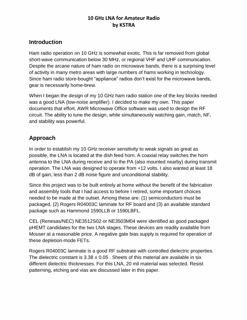
10 GHz LNA for Amateur Radio by K5TRA Introduction Ham radio operation on 10 GHz is somewhat exotic. This is far removed from global short-wave communication below 30 MHz, or regional VHF and UHF communication. Despite the arcane nature of ham radio on microwave bands, there is a surprising level of activity in many metro areas with large numbers of hams working in technology. Since ham radio store-bought “appliance” radios don’t exist for the microwave bands, gear is necessarily home-brew. When I began the design of my 10 GHz ham radio station one of the key blocks needed was a good LNA (low-noise amplifier). I decided to make my own. This paper documents that effort. AWR Microwave Office software was used to design the RF circuit. The ability to tune the design, while simultaneously watching gain, match, NF, and stability was powerful. Approach In order to establish my 10 GHz receiver sensitivity to weak signals as great as possible, the LNA is located at the dish feed horn. A coaxial relay switches the horn antenna to the LNA during receive and to the PA (also mounted nearby) during transmit operation. The LNA was designed to operate from +12 volts. I also wanted at least 18 dB of gain, less than 2 dB noise figure and unconditional stability. Since this project was to be built entirely at home without the benefit of the fabrication and assembly tools that I had access to before I retired, some important choices needed to be made at the outset. Among these are: (1) semiconductors must be packaged, (2) Rogers R04003C laminate for RF board and (3) an available standard package such as Hammond 1590LLB or 1590LBFL. CEL (Renesas/NEC) NE3512S02 or NE3503M04 were identified as good packaged pHEMT candidates for the two LNA stages. These devices are readily available from Mouser at a reasonable price. A negative gate bias supply is required for operation of these depletion-mode FETs. Rogers R04003C laminate is a good RF substrate with controlled dielectric properties. The dielectric constant is 3.38 ± 0.05 . Sheets of this material are available in six different dielectric thicknesses. For this LNA, 20 mil material was selected. Resist patterning, etching and vias are discussed later in this paper.

Welcome message from author
This document is posted to help you gain knowledge. Please leave a comment to let me know what you think about it! Share it to your friends and learn new things together.
Transcript
10 GHz LNA for Amateur Radio by K5TRA
Introduction
Ham radio operation on 10 GHz is somewhat exotic. This is far removed from global
short-wave communication below 30 MHz, or regional VHF and UHF communication.
Despite the arcane nature of ham radio on microwave bands, there is a surprising level
of activity in many metro areas with large numbers of hams working in technology.
Since ham radio store-bought “appliance” radios don’t exist for the microwave bands,
gear is necessarily home-brew.
When I began the design of my 10 GHz ham radio station one of the key blocks needed
was a good LNA (low-noise amplifier). I decided to make my own. This paper
documents that effort. AWR Microwave Office software was used to design the RF
circuit. The ability to tune the design, while simultaneously watching gain, match, NF,
and stability was powerful.
Approach
In order to establish my 10 GHz receiver sensitivity to weak signals as great as
possible, the LNA is located at the dish feed horn. A coaxial relay switches the horn
antenna to the LNA during receive and to the PA (also mounted nearby) during transmit
operation. The LNA was designed to operate from +12 volts. I also wanted at least 18
dB of gain, less than 2 dB noise figure and unconditional stability.
Since this project was to be built entirely at home without the benefit of the fabrication
and assembly tools that I had access to before I retired, some important choices
needed to be made at the outset. Among these are: (1) semiconductors must be
packaged, (2) Rogers R04003C laminate for RF board and (3) an available standard
package such as Hammond 1590LLB or 1590LBFL.
CEL (Renesas/NEC) NE3512S02 or NE3503M04 were identified as good packaged
pHEMT candidates for the two LNA stages. These devices are readily available from
Mouser at a reasonable price. A negative gate bias supply is required for operation of
these depletion-mode FETs.
Rogers R04003C laminate is a good RF substrate with controlled dielectric properties.
The dielectric constant is 3.38 ± 0.05 . Sheets of this material are available in six
different dielectric thicknesses. For this LNA, 20 mil material was selected. Resist
patterning, etching and vias are discussed later in this paper.
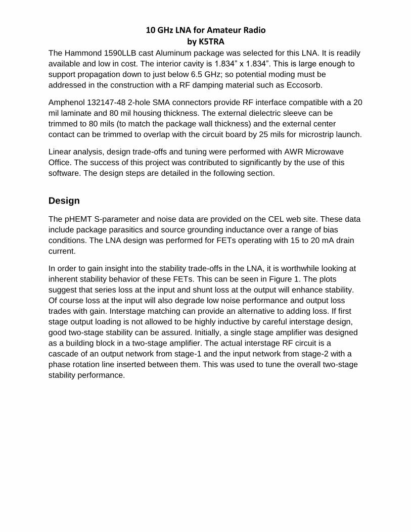
10 GHz LNA for Amateur Radio by K5TRA
The Hammond 1590LLB cast Aluminum package was selected for this LNA. It is readily
available and low in cost. The interior cavity is 1.834” x 1.834”. This is large enough to
support propagation down to just below 6.5 GHz; so potential moding must be
addressed in the construction with a RF damping material such as Eccosorb.
Amphenol 132147-48 2-hole SMA connectors provide RF interface compatible with a 20
mil laminate and 80 mil housing thickness. The external dielectric sleeve can be
trimmed to 80 mils (to match the package wall thickness) and the external center
contact can be trimmed to overlap with the circuit board by 25 mils for microstrip launch.
Linear analysis, design trade-offs and tuning were performed with AWR Microwave
Office. The success of this project was contributed to significantly by the use of this
software. The design steps are detailed in the following section.
Design
The pHEMT S-parameter and noise data are provided on the CEL web site. These data
include package parasitics and source grounding inductance over a range of bias
conditions. The LNA design was performed for FETs operating with 15 to 20 mA drain
current.
In order to gain insight into the stability trade-offs in the LNA, it is worthwhile looking at
inherent stability behavior of these FETs. This can be seen in Figure 1. The plots
suggest that series loss at the input and shunt loss at the output will enhance stability.
Of course loss at the input will also degrade low noise performance and output loss
trades with gain. Interstage matching can provide an alternative to adding loss. If first
stage output loading is not allowed to be highly inductive by careful interstage design,
good two-stage stability can be assured. Initially, a single stage amplifier was designed
as a building block in a two-stage amplifier. The actual interstage RF circuit is a
cascade of an output network from stage-1 and the input network from stage-2 with a
phase rotation line inserted between them. This was used to tune the overall two-stage
stability performance.

10 GHz LNA for Amateur Radio by K5TRA
Fig. 1 pHEMT Stability regions and conjugate port impedances
Fig. 2 Two-Stage 10 GHz LNA schematic

10 GHz LNA for Amateur Radio by K5TRA
The overall amplifier schematic can be seen in Figure 2. Gate and drain bias networks
are comprised of a high impedance ¼ line that is terminated by a low impedance,
bypassed, DC feed circuit. A low impedance (near short circuit) for in-band frequencies
is provided by an open-circuit ¼ radial stub. The DC feed path is also decoupled and
damped by series resistance.
The +12 volt DC input is first dropped to a regulated 3.3 volt rail, followed by a 2.5 volt
regulator. The 3.3 volt rail feeds the collector of two emitter follower pass transistors for
drain supply of the two LNA FETs. The 3.3 volt rail also powers the negative voltage
generator IC (MAX1044) for the LNA FET gate bias. The 2.5 volt regulator provides a
base reference voltage for the emitter followers. At turn-on, the rise in base voltage is
delayed by a RC circuit to sequence the gate negative supply before the drain positive
supply. The emitter followers also provide supply path isolation between RF stages.
The RF cascade is represented in Figure 3. Details of the Input, Interstage, and Output
RF matching networks can be seen in Figures 4,5, and 6.
Fig.3 LNA RF circuit cascade
Fig. 4 LNA input RF circuit

10 GHz LNA for Amateur Radio by K5TRA
Fig. 5 LNA interstage RF circuit
Fig. 6 LNA output RF circuit
The overall simulated gain, port match, and noise performance are shown in Figures 7,
8 and 9. For amateur (ham) radio operation, the frequency region of most interest is
10.368 GHz. The overall swept performance is not extremely narrow. Figure 9 shows a
wide (2.5 octave) sweep. No extreme peaks in gain are seen at lower, out of band,
frequencies.

10 GHz LNA for Amateur Radio by K5TRA
Fig. 7 Overall LNA gain, port match, and noise performance
Fig.8 LNA port impedances

10 GHz LNA for Amateur Radio by K5TRA
Fig. 9 Wide sweep of LNA gain, port match, and noise performance
The well behaved out of band behavior displayed in Figure 9 suggests that the stability
of the LNA will be good. A detailed stability analysis confirms this. Figures 10, 11 and 12
display the details of this analysis. For unconditional stability, Rollett’s K factor must be
greater than unity and the B1 parameter must remain positive. This can be seen in
Figure 10. Figures 11 and 12 show that NO possible port terminating passive
impedances can cause instability.

10 GHz LNA for Amateur Radio by K5TRA
Fig.10 LNA stability parameters K and B1
Fig. 11 LNA input stability Fig. 12 LNA output stability
The layout of the LNA is shown in Figure 13. The RF input is on the right and output is
on the left edge. Layouts were done for both NE3512S02 and NE3503M04 pHEMTs.
Figure 13 shows the NE3512S02 pattern. In order to pattern resist for etching, this
layout was mirrored, as seen in Figure 14.

10 GHz LNA for Amateur Radio by K5TRA
Fig. 13 LNA layout
Fig. 14 Mirrored LNA layout

10 GHz LNA for Amateur Radio by K5TRA
Construction
Construction of the LNA begins with resist patterning and etching of the circuit board. I
use a laser printer to define a 1:1 mirrored image of the layout on a sheet similar to
mylar. The product is called ‘Press-n-Peel’. This resist pattern is transferred to a clean
board with temperature and pressure. The board is then etched in a homemade bubble
etcher and finished with a thin tin plate. Via holes are defined with a 35 mil drill. Figure
15 shows the undrilled, etched board placed in the undrilled housing. The via holes
were drilled with the board placed in the housing as depicted in Figure 15. The depth of
the drill was sufficient to pass through the board and mark the floor of the housing. In
this way the locations of the vias were marked in the housing. With my homebrew board
process, it is necessary to solder wires in the through holes at each via location. After
the excess wire is nipped as short as possible, there remains a small bump below each
via. Each drill marked location in the floor must be relieved with a clearance recess. So
the floor will have an array of ‘divots’ before the assembled board is attached. A
commercial PC board shop would eliminate all of the difficulties described here;
however, the cost for single board prototyping on Rogers material is prohibitive for a
home project.
Fig. 15 Etched, undrilled board placed in undrilled housing
An interior view of the completed LNA is show in Figure 16. The input is on the right and
output on the left. The 3.3 volt regulator can be seen on the left wall. The DC circuitry
can clearly be seen along the top of the board and the RF amplifier stages on the lower
portion. Four small rectangles of Eccosorb can also be seen attached to DC bias feed
lines. This was just done for practical reasons as insurance against parasitic feedback

10 GHz LNA for Amateur Radio by K5TRA
paths. It is likely that they are not needed. As stated earlier, moding suppression is
needed in this housing because 10 GHz will propagate through a cavity this large.
Eccosorb patches are placed on the right and lower side walls as well as on the inside
of the cover. Stability behavior has been excellent.
Fig. 16 Interior view of completed LNA
Fig. 17 Completed 10 GHz LNA
The completed LNA can be seen in Figure17. The measured gain is just over +18 dB
and the associated NF is near 2 dB. While this meets my performance targets for use in

10 GHz LNA for Amateur Radio by K5TRA
my 10 GHz station, the predicted levels are a bit better. I attribute the differences to
poor line width control and excess via inductance in my home fabricated circuit board.
For maximum receiver sensitivity (minimum system noise figure), losses between the
dish feed horn and the LNA must be minimal. Similarly, on the transmit side, losses
between the power amplifier and the dish feed horn must be kept to a minimum. While
most of the transmit and receive circuitry is located in the transverter (also home brew)
shown in Figure 18, the LNA and PA are mounted with the feed horn at the dish.
Fig. 18 10 GHz transverter (transmit & receive converter)
Figure 19 shows the LNA, coaxial relay, PA, isolator and feed horn. The LNA can be seen on the
right and PA on the left. The back or the feed horn can be seen at the top of the bracket. A side
view of this assembly can be seen in Figure 20.

10 GHz LNA for Amateur Radio by K5TRA
Fig. 19 Dish horn feed assembly with LNA and PA
Fig. 20 Side view of dish horn feed assembly with LNA and PA
10 GHz LNA for Amateur Radio by K5TRA
On air results have been outstanding. There are half a dozen hams with 10 GHz
stations within 50 miles. I can communicate with all of them on a routine basis. I have a
hilltop location with a good view in all directions. The most distant of these ‘locals’ is
located 45 miles away; yet, we can talk with strong signal levels anytime. The most
exciting contact occurred early one morning when ducting and scatter conditions
supported unusually long path propagation. I was able to contact a station in Allen
Texas (north of Dallas) 213 miles away!
For more information on this topic: http://k5tra.net/10GHz.html .
I again wish to acknowledge AWR’s Microwave Office software that was used in the
design of this LNA.
Related Documents