1 Web-Enabled Decision Support Systems Relational Data Modeling and Normalization Prof. Name [email protected] Position (123) 456-7890 University Name

1 Web-Enabled Decision Support Systems Relational Data Modeling and Normalization Prof. Name [email protected] Position (123) 456-7890 University Name.
Dec 27, 2015
Welcome message from author
This document is posted to help you gain knowledge. Please leave a comment to let me know what you think about it! Share it to your friends and learn new things together.
Transcript

1
Web-Enabled Decision Support Systems
Relational Data Modeling and Normalization
Prof. Name [email protected] (123) 456-7890University Name

2
Overview
4.1 Introduction 4.2 The Relational Data Model 4.3 Relational Keys 4.4 Relational Data Integrity Constraints 4.5 Transforming E-R Diagrams into Relational Schemas 4.6 Case Study: Logical Design for a University Database 4.7 Introduction to Normalization 4.8 Data Redundancy 4.9 Database Anomalies 4.10 Functional Dependencies 4.11 Forms of Normalization 4.12 In-Class Assignment 4.13 Summary

3
Introduction
In the previous chapter, we described conceptual database design using object-based entity-relationship (E-R) data modeling
The objective of a logical database design is to transform the conceptual data model into a set of relations used for physical database design
We describe logical database design using record-based relational data modeling– Widely used in contemporary database applications
– General modeling approach

4
Overview
4.1 Introduction 4.2 The Relational Data Model 4.3 Relational Keys 4.4 Relational Data Integrity Constraints 4.5 Transforming E-R Diagrams into Relational Schemas 4.6 Case Study: Logical Design for a University Database 4.7 Introduction to Normalization 4.8 Data Redundancy 4.9 Database Anomalies 4.10 Functional Dependencies 4.11 Forms of Normalization 4.12 In-Class Assignment 4.13 Summary

5
Relational Data Model
First introduced by IBM’s E.F. Codd in the 1970s
Based on mathematical concept of a relation
Physically represented as a relation or a table that stores data
Consists of three components:– Relational data structure
Where data is organized
– Data manipulation Operations used to manipulate data stored in the data structure
– Relational data integrity Rules that maintain the integrity of data when manipulated

6
Relational Data Structure
A relation is the main data structure that stores and organizes data in the relational data model – Two-dimensional grid that holds data about the object in the database
E-R Diagram and Relational Schema for the Student Relation

7
Relational Data Structure (cont.)
A column of a relation is referred to as an attribute– The number of attributes in a relation is called the degree of the relation
A row is referred to as a record or a tuple – The number of records in a relation is defined as the cardinality of the
relation
Relational schema example:– STUDENT (SSN, Name, Email, DeptName)

8
Properties of a Relation
Each relation is uniquely identified by its name
Each cell of a relation contains exactly one (atomic) value
Each record of a relation is unique
Each attribute in a relation has a distinct name
The values of an attribute are from the same domain
The order of attributes is irrelevant
The order of records is also irrelevant
9
Data Manipulation
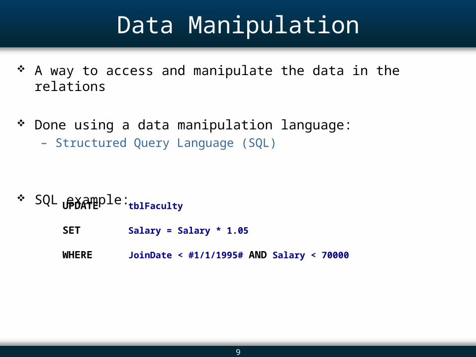
A way to access and manipulate the data in the relations
Done using a data manipulation language:– Structured Query Language (SQL)
SQL example:
UPDATE tblFaculty
SET Salary = Salary * 1.05
WHERE JoinDate < #1/1/1995# AND Salary < 70000

10
Overview
4.1 Introduction 4.2 The Relational Data Model 4.3 Relational Keys 4.4 Relational Data Integrity Constraints 4.5 Transforming E-R Diagrams into Relational Schemas 4.6 Case Study: Logical Design for a University Database 4.7 Introduction to Normalization 4.8 Data Redundancy 4.9 Database Anomalies 4.10 Functional Dependencies 4.11 Forms of Normalization 4.12 In-Class Assignment 4.13 Summary

11
Relational Keys
We need to specify one or more attributes (relational keys) that uniquely identify each record in a relation
A super key is a set of one or more attributes that uniquely identifies each record in a relation
A candidate key is a minimal super key (one that has a minimum number of attributes)

12
Primary and Composite Keys
A primary key is a candidate key that has been selected to uniquely identify records in a relation – Selection of primary key:
It must be unique within its domain at all times
The candidate key can never change
It cannot hold a NULL value
A composite key is a key that has more than one attribute

13
Foreign Key
A foreign key is an attribute or a set of attributes in a relation that serves as a primary key of the same or some other relation
Student and Department Relations Illustrating Foreign Keys (DeptName)
Foreign Key
Primary Key

14
About NULL
Situations where attribute cannot be assigned with a data value – There is no applicable data value
– When the value is unknown
Assign NULL value in such situations
NULL means that the value is either unknown or is not applicable
NULL is not same as zero or white space

15
Overview
4.1 Introduction 4.2 The Relational Data Model 4.3 Relational Keys 4.4 Relational Data Integrity Constraints 4.5 Transforming E-R Diagrams into Relational Schemas 4.6 Case Study: Logical Design for a University Database 4.7 Introduction to Normalization 4.8 Data Redundancy 4.9 Database Anomalies 4.10 Functional Dependencies 4.11 Forms of Normalization 4.12 In-Class Assignment 4.13 Summary

16
Integrity Constraints
There are three types of data integrity constraints:– Domain constraints
– Entity constraints
– Referential constraints

17
Domain Constraints
A domain is the set of values that can be assigned to an attribute
The domain constraint states that all the values of an attribute must be from the same domain
The Domain Definition

18
Entity Constraints
Entity constraints ensure that every relation of a relational data model has a primary key and that the value of the primary key cannot be NULL
Proof:1. Primary key:
Minimal set of attributes that uniquely identify tuples
2. Say primary key can have nulls: We don’t need all attributes of a primary key to identify the tuples uniquely
3. CONTRADICTION!
19
Referential Constraints
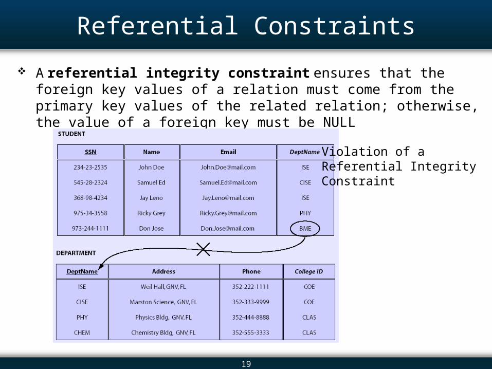
A referential integrity constraint ensures that the foreign key values of a relation must come from the primary key values of the related relation; otherwise, the value of a foreign key must be NULL
Violation of a Referential Integrity Constraint

20
Referential Constraints (cont.)
Representation:– Add an arrow starting from foreign key attribute(s) pointing to the associated
primary key attribute(s)
Graphical Representation of a Relational Schema

21
Overview
4.1 Introduction 4.2 The Relational Data Model 4.3 Relational Keys 4.4 Relational Data Integrity Constraints 4.5 Transforming E-R Diagrams into Relational Schemas 4.6 Case Study: Logical Design for a University Database 4.7 Introduction to Normalization 4.8 Data Redundancy 4.9 Database Anomalies 4.10 Functional Dependencies 4.11 Forms of Normalization 4.12 In-Class Assignment 4.13 Summary

22
Task 1: Transforming Regular Entities
1. Transform a regular entity type in an E-R diagram into a relation.
2. Assign the entity name in an E-R diagram as a relation name.
3. Make each simple attribute of a regular entity an attribute of a relation.
4. Make the identifier of the regular entity type the primary key of a relation.
Transformation of a Regular Entity

23
Task 2: Transforming Composite Attributes
1. Include simple attributes of a composite attribute in the relation.
Transformation of a Composite Attribute

24
Task 3: Transforming Multi-Valued Attributes
1. Transform a regular entity as described; however, do not add any multi-valued attributes to the relation.
2. Create a new relation (one for each multi-valued attribute). – The new relation should have two attributes:
Identifier of a regular entity Multi-valued attribute
– The name of the new relation should be a logical name that reflects the meaning of a multi-valued attribute.
3. The primary key of a new relation is a composite key. – The two attributes of a new relation together serve as its primary key.

25
Task 3: Transforming Multi-Valued Attributes
Transformation of Multi-Valued Attribute

26
Task 4: One-to-Many Unary Relationships
One-to-Many Unary Relationships:1. Transform an entity of a unary relationship as a regular entity as described
previously.
2. Add a new attribute, primary key of the same relation as a foreign key.
3. Draw an arrow that originates from the foreign key and points towards the primary key.
Student Relation After Transformation

27
Task 4: One-to-Many Unary Relationships
Transformation of a Unary One-to-Many Relationship

28
Task 4: Many-to-Many Unary Relationships
Many-to-Many Unary Relationships:1. Transform the entity of a unary relationship as a regular entity.
2. Create and name a new relation to represent the many-to-many relationship.
3. The new relation gets the primary key of the entity and a second attribute representing the many-to-many relationship. Primary key of the new relation is a composite key of the two foreign keys.
4. Draw referential integrity arrows for the foreign keys.
5. Add any attributes of the many-to-many relationship in the new relation.

29
Task 4: Many-to-Many Unary Relationships
Transformation of a Unary Many-to-Many Relationship

30
Task 4: Many-to-Many Unary Relationships
Relation Item and the New Relation Component After Transformation

31
Task 5: One-to-One Binary Relationships
1. Create two relations, one for each entity. – Transform each entity into a relation as a regular entity.
2. Include the primary key of one relation as a foreign key to the other relation. – Mandatory side migrates towards the optional side.
3. Show the referential integrity constraint.
4. Any attributes on the relationship along with the foreign key migrate toward the optional side of the relationship.

32
Task 5: One-to-One Binary Relationships
Transformation of a Binary One-to-One Relationship

33
Task 5: One-to-One Binary Relationships
Employee and Workstation Relations After Transformation

34
Task 5: One-to-Many Binary Relationships
1. Create two relations, one for each entity. – Transform each entity into a relation as a regular entity.
2. The primary key of a relation on the “one” side of the relationship migrates towards the relation on the “many” side of the relationship. – Show referential integrity constraints.
3. Any attributes on the relationship along with the foreign key migrate toward the relation on the “many” side of the relationship.

35
Task 5: One-to-Many Binary Relationships
Transformation of a Binary One-to-Many Relationship

36
Task 5: One-to-Many Binary Relationships
Student and Department Relations After Transformation

37
Task 5: Many-to-Many Binary Relationships
1. Create two relations, one for each entity. – Transform each entity into a relation as a regular entity.
2. Create a third new relation to represent the many-to-many relationship.
3. Primary key from both the relations migrates to the new relation.
4. Show referential integrity constraints.
5. Primary key of the new relation is a composite key with foreign keys of relations.
6. Any attributes of the relationship migrate toward the intermediate relation.

38
Task 5: Many-to-Many Binary Relationships
Transformation of Binary Many-to-Many Telationship

39
Task 5: Many-to-Many Binary Relationships
Transformed Binary Many-to-Many Relationship

40
Task 6: Transforming Ternary Relationships
1. Create three relations, one for each entity in a ternary relationship. – Transform each entity into a relation as a regular relation.
2. Create a fourth relation that represents the ternary relationship.
3. Primary key from the first three relations migrates to the new relations.
4. Show referential integrity constraints.
5. The three foreign keys of the new relation together serve as a composite primary key.
6. Any attributes of the relationship migrate toward the intermediate relation.

41
Task 6: Transforming Ternary Relationships
Transformation of a Ternary Relationship

42
Task 6: Transforming Ternary Relationships
Transformed Ternary Relationship

43
Task 7: Transforming Superclass/Subclass Relationships
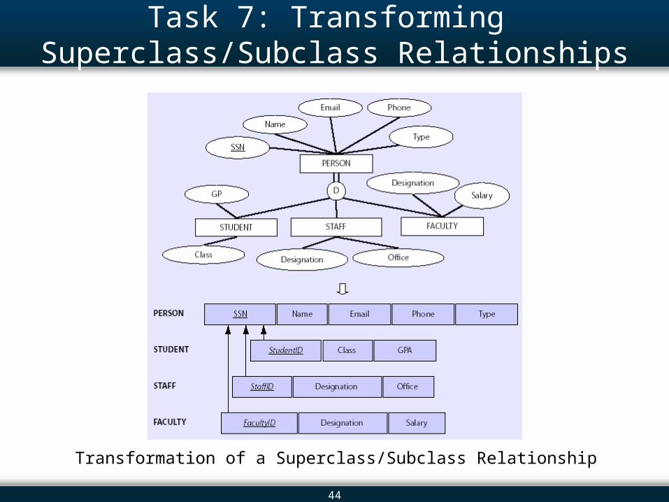
1. Create a separate relation for the superclass and each subclass entity. – Transform each entity into a relation as a regular entity.
2. All common attributes of superclass entity are assigned to the relation for the subclass entity. – Identifier of the superclass serves as the primary key for the superclass
relation.
3. Assign attributes unique to each subclass to each subclass relation. – Primary key of superclass migrates as a foreign key to each subclass
relation.
4. Transform the subclass discriminator as a multi-valued attribute in case of the overlap rule of EER.
44
Task 7: Transforming Superclass/Subclass Relationships
Transformation of a Superclass/Subclass Relationship

45
Task 7: Transforming Superclass/Subclass Relationships
Transformed Superclass/Subclass Relationship

46
Task 8: Transforming Weak Entities
1. Create a relation for the owner entity type.
2. Create a new relation for a weak entity type and transform it as a regular entity.
3. Include the primary key of the owner relation as a foreign key. – Show referential integrity constraints.
4. Primary key of the new relation is the composite key formed by partial identifier attributes of the weak entity and a foreign key.

47
Task 8: Transforming Weak Entities
Transformation of a Weak Entity

48
Task 9: Transforming Associative Entities
1. Create two relations, one for each entity types. – Transform them as regular entities.
2. Create another relation for the associative entity and transform it as a regular entity.
3. Add the primary key of relations for participating entities as a foreign key for the new relation. – Associative entity with its own identifier becomes primary key for that
relation.
– If associative entity does not have its own identifier, the keys of the participating entities serve as the composite primary key.

49
Task 9: Transforming Associative Entities
Transformation of an Associative Entity With an Identifier

50
Overview
4.1 Introduction 4.2 The Relational Data Model 4.3 Relational Keys 4.4 Relational Data Integrity Constraints 4.5 Transforming E-R Diagrams into Relational Schemas 4.6 Case Study: Logical Design for a University Database 4.7 Introduction to Normalization 4.8 Data Redundancy 4.9 Database Anomalies 4.10 Functional Dependencies 4.11 Forms of Normalization 4.12 In-Class Assignment 4.13 Summary

51
Case Study: Logical Design for a University DB
The Relational Schema for the University Database

52
Overview
4.1 Introduction 4.2 The Relational Data Model 4.3 Relational Keys 4.4 Relational Data Integrity Constraints 4.5 Transforming E-R Diagrams into Relational Schemas 4.6 Case Study: Logical Design for a University Database 4.7 Introduction to Normalization 4.8 Data Redundancy 4.9 Database Anomalies 4.10 Functional Dependencies 4.11 Forms of Normalization 4.12 In-Class Assignment 4.13 Summary

53
Normalization
Normalization refers to a series of tests performed on relations to determine whether they satisfy or violate the requirements of a normal form.
Technique of decomposing given relations to produce smaller, well-structured sets of relations with desirable properties.

54
Overview
4.1 Introduction 4.2 The Relational Data Model 4.3 Relational Keys 4.4 Relational Data Integrity Constraints 4.5 Transforming E-R Diagrams into Relational Schemas 4.6 Case Study: Logical Design for a University Database 4.7 Introduction to Normalization 4.8 Data Redundancy 4.9 Database Anomalies 4.10 Functional Dependencies 4.11 Forms of Normalization 4.12 In-Class Assignment 4.13 Summary

55
Data Redundancy
Data redundancy is having duplicate data in the database – Increases use of disk storage
– Reduces efficiency of data updates
Data Redundancies

56
Overview
4.1 Introduction 4.2 The Relational Data Model 4.3 Relational Keys 4.4 Relational Data Integrity Constraints 4.5 Transforming E-R Diagrams into Relational Schemas 4.6 Case Study: Logical Design for a University Database 4.7 Introduction to Normalization 4.8 Data Redundancy 4.9 Database Anomalies 4.10 Functional Dependencies 4.11 Forms of Normalization 4.12 In-Class Assignment 4.13 Summary

57
Database Anomalies
Relations with redundant data may cause additional inconsistency problems known as anomalies
– Example: VETOFFICE (ClientID, Client Name, PetID, PetName, PetWt, VetID, VetName)
The VetOffice Relation

58
Database Anomalies (cont.)
Insertion Anomalies:– Inserting a new record for veterinarian will leave the values of VetID and
VetName to be NULL in the Client relation. This is prohibited.
Deletion Anomalies:– If we delete all records for a client, the deletion does not reflect in the records
for all vets who work for that client. Critical data is deleted.
Update Anomalies:– If the weight for a certain pet updated, all records that feature this pet’s
weight need to be updated.

59
Overview
4.1 Introduction 4.2 The Relational Data Model 4.3 Relational Keys 4.4 Relational Data Integrity Constraints 4.5 Transforming E-R Diagrams into Relational Schemas 4.6 Case Study: Logical Design for a University Database 4.7 Introduction to Normalization 4.8 Data Redundancy 4.9 Database Anomalies 4.10 Functional Dependencies 4.11 Forms of Normalization 4.12 In-Class Assignment 4.13 Summary

60
Functional Dependency
Functional dependency is a relationship among attributes– An attribute B is functionally dependent of attribute A, if given a value of A,
value of B is uniquely defined
– Denoted as A B
– Each valid value of A maps exactly to one value of B
Normalization is based on the analysis of functional dependencies within a relation
61
Functional Dependency (cont.)
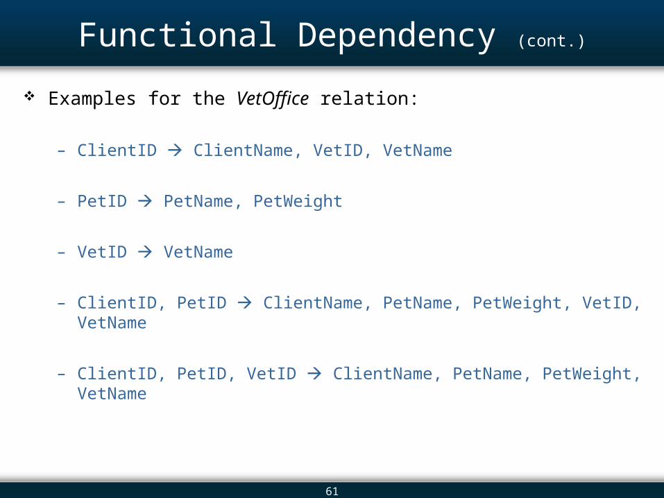
Examples for the VetOffice relation:
– ClientID ClientName, VetID, VetName
– PetID PetName, PetWeight
– VetID VetName
– ClientID, PetID ClientName, PetName, PetWeight, VetID, VetName
– ClientID, PetID, VetID ClientName, PetName, PetWeight, VetName

62
Determinants
Determinants are the attribute(s) on the left-hand side of the arrow in a functional dependency representation
Examples: – ClientID, PetID, and ClientID-PetID from the previous slide
If all attributes appear in the functional dependency representation then the determinant is the super key
This helps in finding out the primary key for the relation– (ClientID, PetID) is the minimal super key and hence is selected as the
primary key

63
Dependency Diagram
A dependency diagram is a pictorial representation of a functional dependency
Dependency Diagram for the VetOffice Relation

64
Types of Functional Dependencies
A partial dependency is a functional dependency in which a non-primary key’s attributes functionally depend on a part of (but not all) the primary key attributes – Example: ClientID ClientName, VetID, VetName
A transitive dependency is a functional dependency in which none of the attributes involves attributes of a primary key– Example: VetID VetName
Partial and Transitive Dependencies

65
Overview
4.1 Introduction 4.2 The Relational Data Model 4.3 Relational Keys 4.4 Relational Data Integrity Constraints 4.5 Transforming E-R Diagrams into Relational Schemas 4.6 Case Study: Logical Design for a University Database 4.7 Introduction to Normalization 4.8 Data Redundancy 4.9 Database Anomalies 4.10 Functional Dependencies 4.11 Forms of Normalization 4.12 In-Class Assignment 4.13 Summary

66
Forms of Normalization
The Normal Forms

67
First Normal Form
A relation is said to be in the first normal form if each cell in the relation contains exactly one value
The VetOffice Relation in Non-1NF Form

68
First Normal Form (cont.)
The VetOffice Relation in 1NF Form

69
Second Normal Form
A relation is said to be in the second normal form if:– It is already in the first normal form
– It has no partial functional dependencies
Example:– The relation from previous slide is in first normal form, but the following partial
dependencies do exist ClientID ClientName, VetID, VetName PetID PetName, PetWeight
Decompose client relation into smaller relations

70
Second Normal Form (cont.)
The Second Normal Form: Client and Pet Relations

71
Third Normal Form
A relation is said to be in the third normal form if: – It is already in the second normal form
– It has no transitive dependencies
Consider the previous slide Client and Pet relations:– Pet is already in third normal form since there are no dependencies
– Client relation has a dependency: VetID VetName
Decompose Client relation further smaller relations

72
Third Normal Form (cont.)
Client, Vet, and Pet Relations in Third Normal Form

73
Boyce-Codd Normal Form
Functional dependencies related to candidate keys may also cause data redundancy.
A relation is said to be in Boyce-Codd Normal (BCNF) form if:– It is already in third normal form
– Every determinant is a candidate key

74
Boyce-Codd Normal Form (cont.)
Example:– STUDENT (StudentID, Major, Advisor, Major-GPA)
Relation is already in third normal form but there are anomalies:– Update anomaly
Change in advisor
– Insertion anomaly A new advisor is added
– Deletion Anomaly Student is removed and if an advisor has only one advisee
Advisor Major has its determinant as a non-candidate key

75
Boyce-Codd Normal Form (cont.)
We change primary key from (StudentID, Major) to (StudentID, Advisor)
This doesn’t help much!– The dependency now becomes a partial dependency
Apply the second normal form and third normal tests again

76
Boyce-Codd Normal Form (cont.)
Student Relation Before BCNF
Student and Advisor Relations in BCNF

77
Principles for Good Database Design
Relations in a well designed database meet the following criteria:– No redundancy
– No partial dependencies
– No transitive dependencies
Guidelines:– Identify entities involved and their relevant attributes and identifiers
– Define relationships between entities
– Draw an E-R / EER diagram to model the problem
– Transform the E-R / EER model to a relational schema
– Normalize the relations up to BCNF

78
Overview
4.1 Introduction 4.2 The Relational Data Model 4.3 Relational Keys 4.4 Relational Data Integrity Constraints 4.5 Transforming E-R Diagrams into Relational Schemas 4.6 Case Study: Logical Design for a University Database 4.7 Introduction to Normalization 4.8 Data Redundancy 4.9 Database Anomalies 4.10 Functional Dependencies 4.11 Forms of Normalization 4.12 In-Class Assignment 4.13 Summary

79
In-Class Assignment
Create a relational schema for a book store that wishes to keep information about the following entities: – BOOK: book name, author name, publication date, and price
– PUBLISHER: publisher’s name, address, and telephone number
– CUSTOMER: customer’s name, address, and reading preferences
Develop an appropriate E-R diagram for the above entities and transform it to a relational schema showing all integrity constraints.– Consider Address as a composite attribute
– Consider ReadingPreferences as a multi-valued attribute

80
Overview
4.1 Introduction 4.2 The Relational Data Model 4.3 Relational Keys 4.4 Relational Data Integrity Constraints 4.5 Transforming E-R Diagrams into Relational Schemas 4.6 Case Study: Logical Design for a University Database 4.7 Introduction to Normalization 4.8 Data Redundancy 4.9 Database Anomalies 4.10 Functional Dependencies 4.11 Forms of Normalization 4.12 In-Class Assignment 4.13 Summary

81
Summary
The relational data model consists of three components:– Relational data structure:
Where data is organized.
– Data manipulation: Operations used to manipulate data stored in the data structure.
– Relational data integrity: Rules that maintain the integrity of data when they are manipulated.
The main data structure that stores and organizes data in the relational data model is a relation, a two-dimensional grid that holds data about the object represented in the database. – A column of a relation is referred to as an attribute.
The number of attributes in a relation is defined as a degree.
– A row is referred to as a record, or a tuple. The number of records in a relation is defined as cardinality.

82
Summary - Keys
A super key is a set of one or more attributes that uniquely identifies each record in a relation.
A candidate key is a super key with a minimum number of attributes.
The primary key is a candidate key that has been selected to identify unique records in a relation.
The foreign key is an attribute or a set of attributes of a relation that serves as a primary key of the same or other relation.

83
Summary - Constraints
The domain constraint states that the values of an attribute must be from the same domain.
Entity constraints ensure that every relation of a relational data model has a primary key and primary key cannot be NULL.
A referential integrity constraint ensures that the foreign key values of a relation must come from the primary key values in the related relation; otherwise, the value of a foreign key must be NULL.

84
Summary - Anomalies
Relations with redundant data may cause inconsistency problems known as anomalies. – Deletion anomalies occur when data has been removed from the database
unintentionally.
– Insertion anomalies occur when we want to add a new record to the relation and not all of the information is available.
– Update anomalies occur when the DBMS must make multiple changes to reflect a single attribute change.

85
Summary - Dependency
A functional dependency is a relationship among attributes.
A dependency diagram is a pictorial representation of a functional dependency.
A partial dependency is a functional dependency in which the non-primary key attributes functionally depend on a part of (but not all) the primary key.
A transitive dependency is a functional dependency in which none of the attributes involves attributes of a primary key.

86
Summary - Normalization
The term normalization, as defined by Codd, refers to a series of tests performed on relations that determines whether a given relation satisfies or violates the requirements of a normal form.
A relation is said to be in the first normal form if each cell in the relation contains exactly one value.
A relation is said to be in the second normal form if it is already in the first normal form and there are no partial functional dependencies.
A relation is said to be in the third normal form if it is already in the second normal form and if it has no transitive dependencies.
A relation is said to be in the BCNF if it is already in the third normal form and if every determinant is a candidate key.

87
Additional Links
Add links here.
Related Documents