1 Version 3.0 Chapter 3 Frame Relay

Welcome message from author
This document is posted to help you gain knowledge. Please leave a comment to let me know what you think about it! Share it to your friends and learn new things together.
Transcript

1Version 3.0
Chapter 3Frame Relay

2Version 3.0
Frame Relay
FR is a WAN Technology.
• Uses (VC) Virtual Circuits to establish connections across the WAN.
• DLCIs are used to identify Virtual Circuits.
• FR can divide a single Physical WAN Interface into multiple Subinterfaces.

3Version 3.0
Frame Relay is an International Telecommunications Standards Sector (ITU-T) and American National Standard Institute (ANSI) standard.

4Version 3.0
Frame Relay is a packet-switched connection oriented WAN service

5Version 3.0
Frame Relay is often used to interconnect LANs
6Version 3.0
The connection through the Frame Relay network between two DTEs is called a virtual circuit (VC)

7Version 3.0
Switched virtual circuits (SVCs) are established dynamically by sending signaling messages to the network.

8Version 3.0
Permanent virtual circuits (PVCs) are preconfigured by the carrier
9Version 3.0
Frame Relay is configured on a serial interface and the default encapsulation type is the Cisco proprietary version of HDLC

10Version 3.0
By default, a Frame Relay network provides non-broadcast multi-access (NBMA) connectivity between remote sites

11Version 3.0
To enable the forwarding of broadcast routing updates in a hub-and-spoke Frame Relay topology, configure the hub router with logically assigned interfaces, called subinterfaces

12Version 3.0
Subinterfaces are logical subdivisions of a physical interface

13Version 3.0

14Version 3.0
Frame Relay Overview• CCITT and American National Standards Institute
(ANSI) are standards that define the process for sending data over a public data network (PDN).
• A data-link technology streamlined to provide high performance and efficiency.
• Operates - Physical and Data Link Layers
• Relies on TCP for error correction.
• The receiving device drops all error frames with no notification to the sender
• Uses - Link Access Procedure for Frame Relay (LAPF)
15Version 3.0
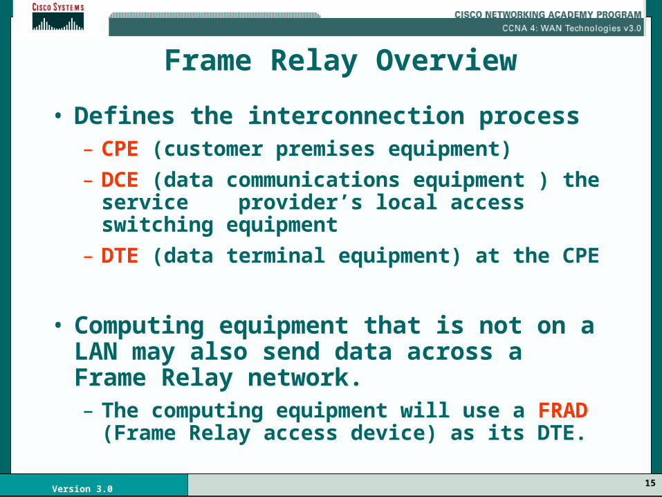
• Defines the interconnection process– CPE (customer premises equipment)
– DCE (data communications equipment ) the service provider’s local access switching equipment
– DTE (data terminal equipment) at the CPE
• Computing equipment that is not on a LAN may also send data across a Frame Relay network. – The computing equipment will use a FRAD
(Frame Relay access device) as its DTE.
Frame Relay Overview

16Version 3.0

17Version 3.0

18Version 3.0
Frame Relay Overview
• The SP’s switching equipment maintains table mapping connection identifiers to outbound ports.
• When a frame is received, the switching device analyzes the connection identifier and delivers the frame to the associated outbound port.
• The complete path to the destination must be established prior to sending the first frame.

19Version 3.0
Frame Relay Overview
• Very cost-effective as:
– FR allows a single interface to support multiple PVCs (private virtual circuits).
– Less equipment required by the customer
– Only pay for the average bandwidth rather than the maximum bandwidth requirement.

20Version 3.0

21Version 3.0
DLCI (Data-link connection identifier)
• A number that identifies the logical circuit between the source and destination device.
• The FR switch maps the DLCIs between each pair of routers to create a PVC (private virtual circuit).
LMI (Local Management Interface)
• A signaling standard between the CPE device and the FR switch - responsible for managing the connection and maintaining status between the devices.

22Version 3.0
LMIs may include:
• support for a keepalive mechanism\• a multicast mechanism that can provide the
network server with its local DLCI
• multicast addressing, providing the ability to give DLCIs global (whole Frame Relay network) significance, rather than just local significance
• a status mechanism, providing an ongoing status on the DLCIs known to the switch
23Version 3.0
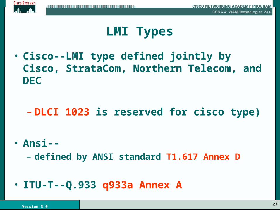
LMI Types
• Cisco--LMI type defined jointly by Cisco, StrataCom, Northern Telecom, and DEC
– DLCI 1023 is reserved for cisco type)
• Ansi--– defined by ANSI standard T1.617 Annex D
• ITU-T--Q.933 q933a Annex A

24Version 3.0
1
2
3
4

25Version 3.0
CIR (Committed information rate)
• The rate, in bits per second, that the Frame Relay switch service agrees to transfer data.
• Bc (Committed Burst)
• Tc The maximum number of bits that the SP agrees to transfer during any Committed Rate Measurement Interval.

26Version 3.0
Excess Burst
• The maximum number of uncommitted bits that the Frame Relay switch will attempt to transfer beyond the CIR.
• Depends on the service offerings available by your vendor, typically limited to the port speed of the local access loop.

27Version 3.0
FECN (Forward explicit congestion notification)• When a FR switch recognizes congestion in the network,
it sends a FECN packet to the destination device indicating that congestion has occurred.
BECN (Backward explicit congestion notification)• When a FR switch recognizes congestion in the network,
it sends a BECN packet to the source router instructing it to reduce the packet rate

28Version 3.0
Discard Eligibility (DE) Indicator
• When the router detects network congestion, the FR switch will first drop packets having the DE bit set.
• The DE bit is set on for oversubscribed traffic - the traffic that was received after the CIR was met.

29Version 3.0
1
2
3
4

30Version 3.0

31Version 3.0
DLCIs
• Frame Relay virtual circuits are identified by DLCIs (data link connection identifiers).
• DLCI values are typically assigned by the Frame Relay service provider
• ONLY local significance, the values themselves are not unique in the Frame Relay WAN.
• Two DTE devices connected by a virtual circuit might use a different DLCI value to refer to the same connection.

32Version 3.0

33Version 3.0
Beginning of the frame
Ending of the frame

34Version 3.0
• Following the leading flags field are two bytes of address information.
– Ten bits of these two bytes make up the actual circuit ID, the DLCI. This is the heart of the Frame Relay header. It identifies the logical connection that is multiplexed into a physical channel.

35Version 3.0
Three of the remaining bits provide congestion control. – The forward explicit congestion notification
(FECN) a bit is set in the Frame to tell the receiving DTE that congestion is experienced in the path from source to destination.
– The backward explicit congestion notification (BECN) bit is set in the Frame traveling in the opposite direction from frames encountering a congested path.

36Version 3.0
– The DE (discard eligibility) bit is set by the DTE to tell the network that a frame has lower importance than other frames and should be discarded before any other frames -- if the network becomes short on resources.
– DE is a very simple priority mechanism.
– This bit is usually set only when the network is congested.

37Version 3.0
Data –
Variable-length field that contains encapsulated upper-layer data.
FCS –
Frame Check Sequence (FCS), used to ensure the integrity of transmitted data.

38Version 3.0

39Version 3.0
Assume two PVCs:
– one between Atlanta and Los Angeles,
– one between San Jose and Pittsburgh.
Los Angeles uses DLCI 12 to refer to its PVC with Atlanta, while
Atlanta refers to the same PVC as DLCI 82.
San Jose uses DLCI 12 to refer to its PVC with Pittsburgh.
Pittsburgh refers to the same PVC as DLCI 62.

40Version 3.0
Reports the status of PVCs

41Version 3.0

42Version 3.0
LMI Purpose
• PVC status – monitors the operational status of the various PVCs
• Transmits keepalive packets:
– to insure that the PVC stays up
– to prevent inactivity, which would shut down the PVC.
43Version 3.0
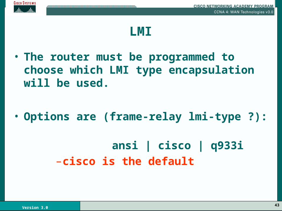
LMI
• The router must be programmed to choose which LMI type encapsulation will be used.
• Options are (frame-relay lmi-type ?):
ansi | cisco | q933i–cisco is the default

44Version 3.0

45Version 3.0
Inverse ARP
The Inverse ARP mechanism allows the router to automatically build the Frame Relay map.
– The router learns the DLCIs that are in use from the switch during the initial LMI exchange.
– The router then sends an Inverse ARP request to each DLCI for each protocol configured on the interface (if the protocol is supported).
– The return information from the Inverse ARP is then used to build the Frame Relay map.

46Version 3.0

47Version 3.0
Frame Relay Mapping
• The router next-hop address determined from the routing table must be resolved to a Frame Relay DLCI.
• The resolution is done through a data structure called a Frame Relay map.
• This data structure may be:– statically configured in the router, or
– the Inverse ARP feature can be used for automatic setup of the map.
49Version 3.0
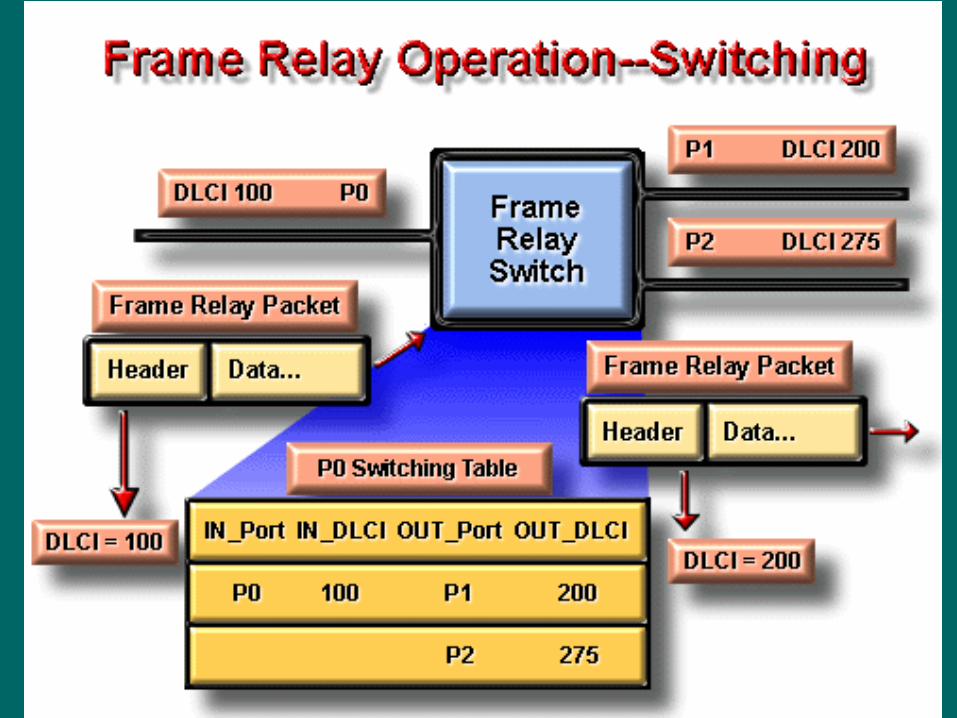
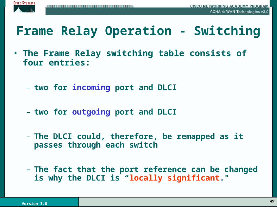
Frame Relay Operation - Switching
• The Frame Relay switching table consists of four entries:
– two for incoming port and DLCI
– two for outgoing port and DLCI
– The DLCI could, therefore, be remapped as it passes through each switch
– The fact that the port reference can be changed is why the DLCI is “locally significant."

51Version 3.0
1. You order Frame Relay service from:
– a service provider, or
– you create a private Frame Relay cloud.
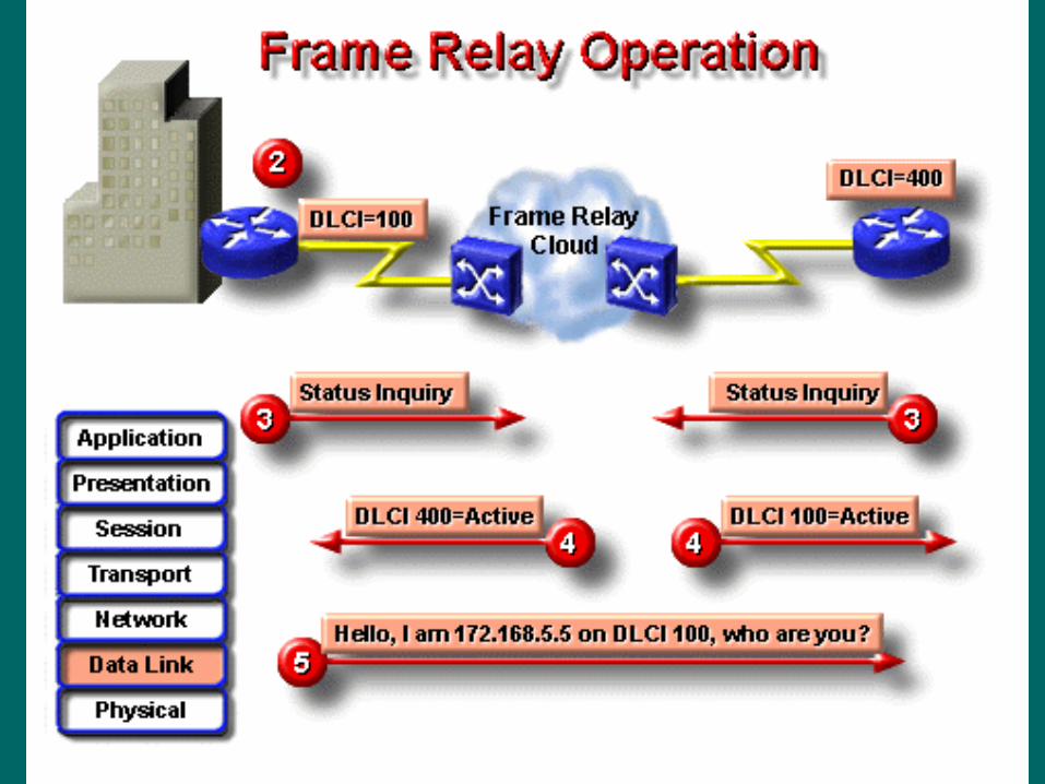
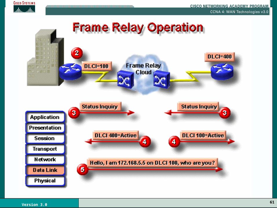
2. Each router, either directly or through a CSU/DSU, connects to the Frame Relay switch.
3. When the CPE router is enabled, it sends a Status Inquiry message to the FR switch.
– The message notifies the switch of the router’s status,
– asks the switch for the connection status of the other remote routers.

52Version 3.0

53Version 3.0
4. When the FR switch receives the request, it responds with a Status message that includes the DLCIs of the remote routers to which the local router can send data.
5. For each active DLCI, each router:– sends an Inverse ARP request packet
introducing itself
– asking for each remote router to identify itself by replying with its network-layer address.

54Version 3.0
55Version 3.0

56Version 3.0
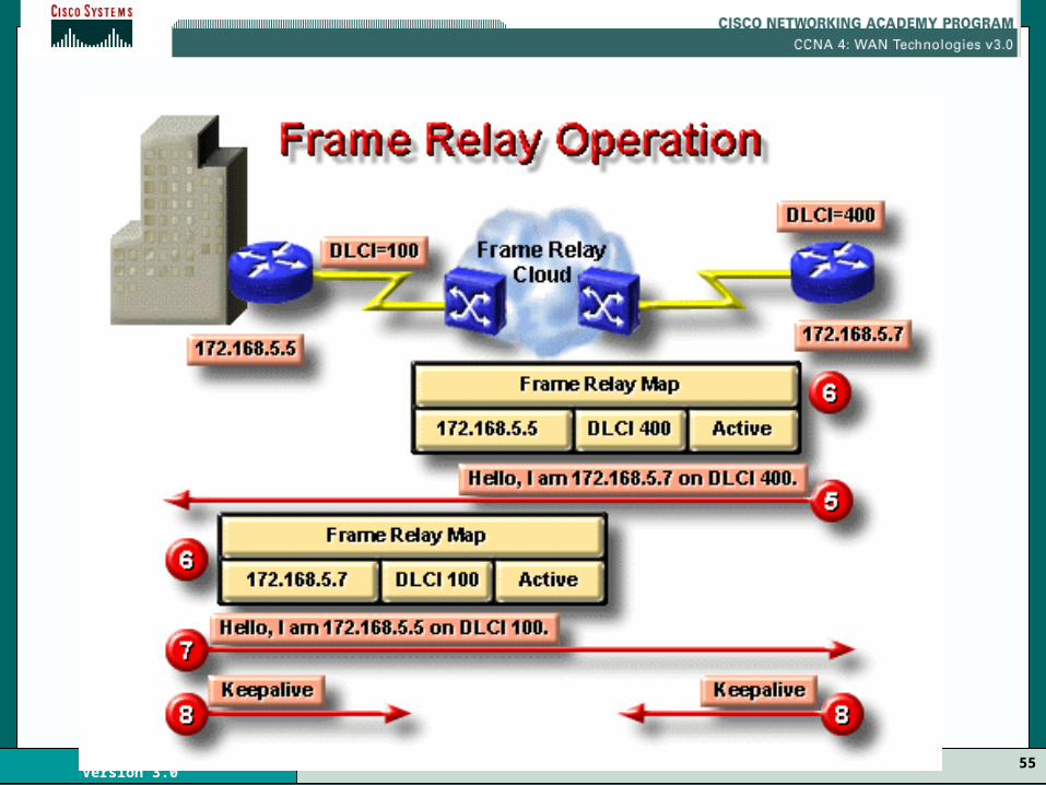
6. (Inverse ARP happens here)
For each DLCI that each router receives an Inverse ARP message about, the router will create a map entry in its Frame Relay map table that includes:
– the local DLCI
– the remote router’s network-layer address,
– as well as the state of the connection
Note: the DLCI is the router’s locally configured DLCI, not the DLCI that the remote router is using.

57Version 3.0
Three possible connection states appear in the Frame Relay map table:
1. Active state —Indicates that the connection is active and that routers can exchange data.
2. Inactive state —Indicates that local connection to FR switch is working, but the remote router’s connection to FR switch is not working.
3. Deleted state —Indicates that NO LMI is being received from the FR switch or NO service between the CPE router and FR switch is occurring.

58Version 3.0
If No Inverse ARP
– If Inverse ARP is not working, or the remote router does not support Inverse ARP, you need to configure the routes (DLCIs and IP addresses) of the remote routers.
– This configuration is referred to as static mapping

59Version 3.0

60Version 3.0
7. Every 60 seconds, the routers exchange Inverse ARP messages.
8. Every 10 seconds or so (this is configurable), the CPE router sends a keepalive message to the FR switch.
– The purpose of the keepalive message is to verify that the FR switch connection is still active.
– The router will change the status of each DLCI, based on the response from the FR switch.
61Version 3.0

62Version 3.0
63Version 3.0
Subinterfaces

64Version 3.0
• More flexible in routing various protocols over partially meshed frame-relay networks.
• Fully meshed FR Partially meshed FR• (Hub & Spoke)
Subinterfaces

65Version 3.0
Point to Point Subinterfaces• Subinterfaces can handle issues caused by
split-horizon over NBMA (Non-Broadcast Multiple Access) networks (like frame-relay) and (distance-vector) routing protocols.
• Split-horizon says that a routing update received on an interface cannot be transmitted out onto that same interface.
66Version 3.0
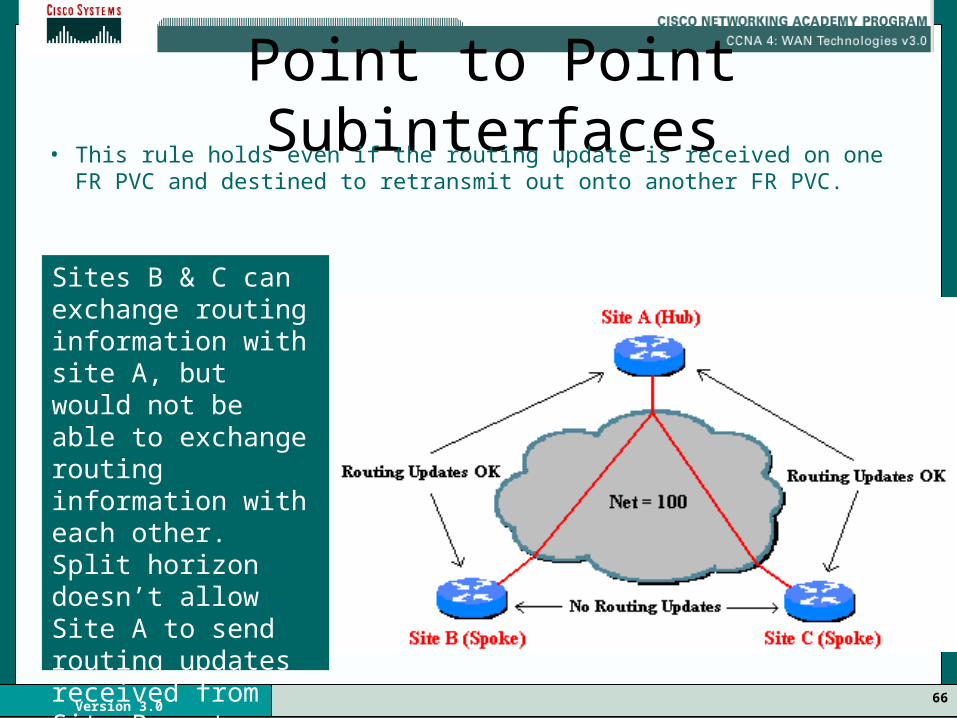
Point to Point Subinterfaces• This rule holds even if the routing update is received on one FR
PVC and destined to retransmit out onto another FR PVC.
Sites B & C can exchange routing information with site A, but would not be able to exchange routing information with each other. Split horizon doesn’t allow Site A to send routing updates received from Site B on to Site C and vice versa.

67Version 3.0
• By dividing the partially-meshed FR network into a number of virtual, point-to-point networks using subinterfaces, the split-horizon problem is fixed.
• Each new point-to-point subnetwork is given its own network number.
Point to Point Subinterfaces

68Version 3.0
Point to Point SubinterfacesTo the routed protocol, each subnetwork
now appears to be located on separate interfaces.
Routing updates received from Site B on one logical point to point subinterface can now be forwarded to site C on a separate logical interface without hurting split horizon.
69Version 3.0
Point to Point Subinterfaces
• A single subinterface is used to establish one PVC connection to another physical or subinterface on a remote router.
• In this case, the interfaces would be:– in the same subnet and – each interface would have a single DLCI
• Each point-to-point connection is its own subnet.
• In this environment, broadcasts are not a problem because the routers are point-to-point and act like a leased line.

70Version 3.0
Multipoint Subinterfaces
• Multipoint subinterfaces are still subject to the split-horizon limitations.
• All nodes attached to a multipoint subinterface belong to the same network number.
• A multipoint subinterface is used to keep remote sites on a single network number while slowly migrating remote sites to their own point-to-point subinterface network.

71Version 3.0
Multipoint Subinterfaces
Here serial 0.1 is a multipoint subinterface that connects to 3 different locations.
All devices on the multipoint subinterface belong to the same network number.
Site E has migrated off the multipoint net to its own point-to-point network. They can co-exist. Site B, C, and D may move to point to point and the multipoint subinterface would now be point-to-point

72Version 3.0
Configuring Frame Relay
73Version 3.0

74Version 3.0
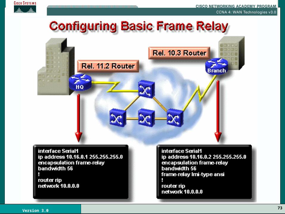
Configuring Basic Frame Relay
• A basic Frame Relay configuration
assumes that you want to:
– Configure Frame Relay on one or more physical interfaces
– That LMI and Inverse ARP are supported by the remote router(s).
75Version 3.0
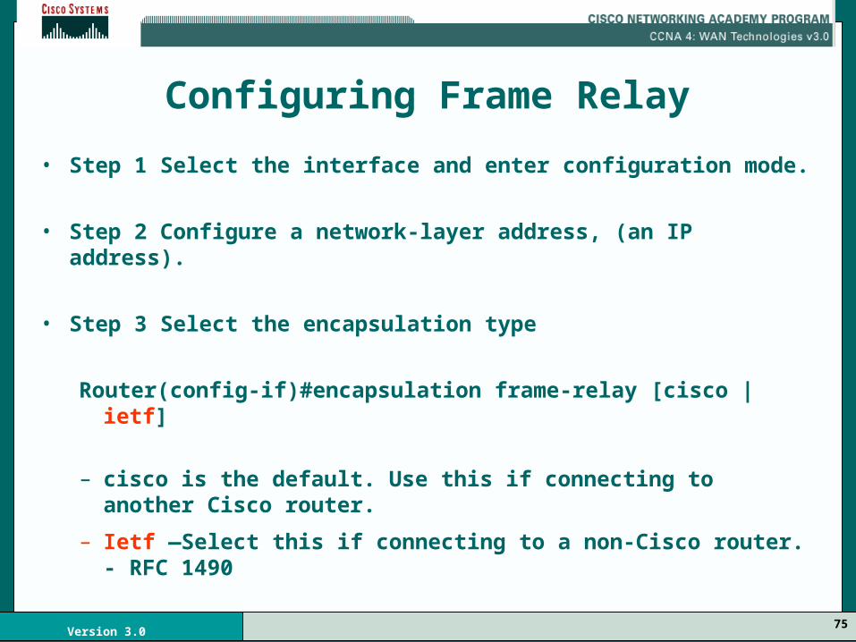
Configuring Frame Relay
• Step 1 Select the interface and enter configuration mode.
• Step 2 Configure a network-layer address, (an IP address).
• Step 3 Select the encapsulation type
Router(config-if)#encapsulation frame-relay [cisco | ietf]
– cisco is the default. Use this if connecting to another Cisco router.
– Ietf —Select this if connecting to a non-Cisco router. - RFC 1490

76Version 3.0
Configuring Frame Relay
• Step 4 If using Cisco IOS Release 11.1 or earlier, specify the LMI-type used by the FR switch:
Router(config-if)#frame-relay lmi-type {ansi | cisco | q933i}
– cisco is the default.
– With IOS Release 11.2 or later, the LMI-type is autosensed so no configuration is required.

77Version 3.0

78Version 3.0
Configuring Frame Relay
• Step 5 Configure the bandwidth for the link.
– This command affects routing operation by protocols such as IGRP, because it is used to help define the metric of the link.
Router(config-if)#bandwidth kilobits

79Version 3.0
Configuring Frame Relay
• Step 6 enable Inverse ARP if disabled– Inverse ARP is on by default.
Router(config-if)#frame-relay inverse-arp [protocol ] [dlci]
• protocol - Supported protocols include ip, ipx, appletalk, decnet, vines, and xns.
• dlci - The DLCI on the local interface that you want to exchange Inverse ARP messages.

80Version 3.0
81Version 3.0

82Version 3.0
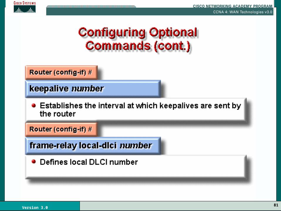
Optional Commands
Router(config-if)# keepalive number (in seconds)
• Increase or decrease keepalive interval.
• You can extend or reduce the interval at which the router interface sends keepalive (status inquiry) messages to the Frame Relay switch.
– This value is usually two to three seconds faster (shorter interval) than the setting of the Frame Relay switch to ensure proper synchronization.
• The default is 10 seconds.

83Version 3.0
84Version 3.0
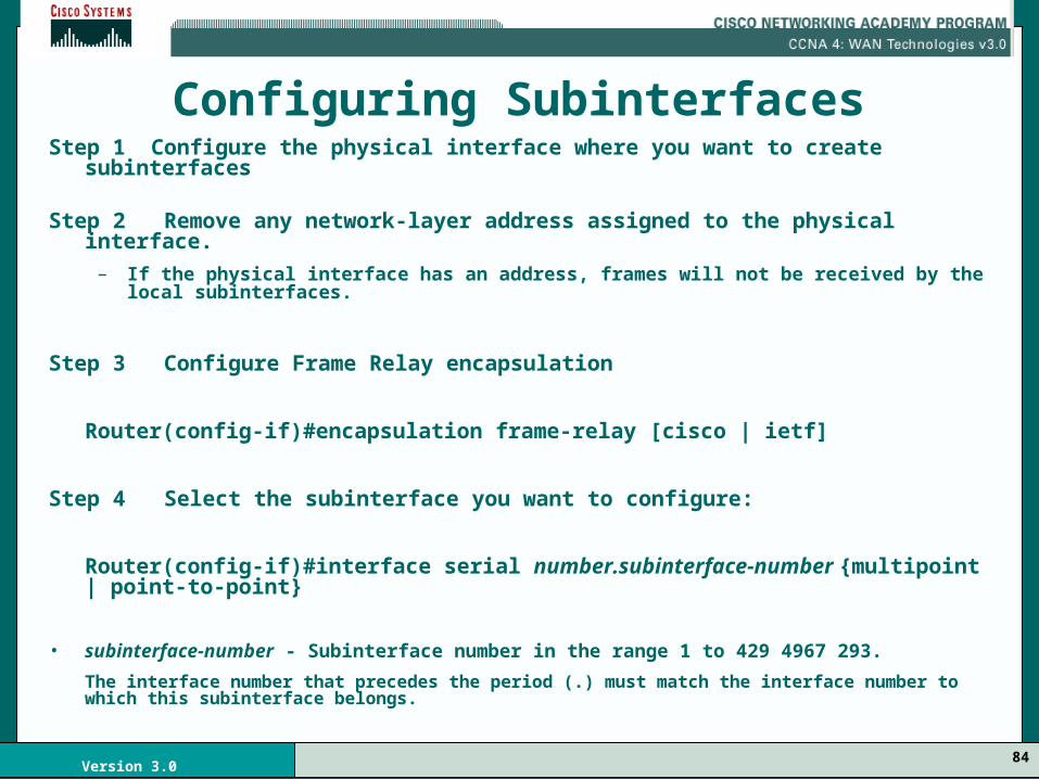
Configuring SubinterfacesStep 1 Configure the physical interface where you want to create subinterfaces
Step 2 Remove any network-layer address assigned to the physical interface.
– If the physical interface has an address, frames will not be received by the local subinterfaces.
Step 3 Configure Frame Relay encapsulation
Router(config-if)#encapsulation frame-relay [cisco | ietf]
Step 4 Select the subinterface you want to configure:
Router(config-if)#interface serial number.subinterface-number {multipoint | point-to-point}
• subinterface-number - Subinterface number in the range 1 to 429 4967 293.
The interface number that precedes the period (.) must match the interface number to which this subinterface belongs.

85Version 3.0
multipoint - Select this if you:
– want the router to forward broadcasts and routing updates that it receives
– are routing IP and you want all routers in same subnet
point-to-point - Select this if you:
– do not want the router to forward broadcasts or routing updates
– want each pair of point-to-point routers to have its own subnet.

86Version 3.0
Configuring Subinterfaces (cont’d)
• Step 5 Configure a network-layer address on the subinterface.
Router(config-if)#ip address ip-add mask
• Step 6 If you configured the subinterface as multipoint or point-to-point, you must configure the local DLCI for the subinterface to distinguish it from the physical interface:
Router(config-if)#frame-relay interface-dlci dlci-number
dlci-number—Defines the local DLCI number being linked to the subinterface.
– This is the only way to link an LMI-derived PVC to a subinterface because LMI does not know about subinterfaces.
MULTI SUB-INTERFACES CANNOT HAVE THE SAME DLCI

87Version 3.0
Configuring Subinterfaces (cont’d)
• If you defined a subinterface for point-to-point communication, you cannot reassign the same subinterface number to be used for multipoint communication without first rebooting the router.
• Instead you can avoid using that subinterface number and use a different subinterface number.

88Version 3.0
Frame Relay Subinterfaces

89Version 3.0
Configuring Point-to-Point Subinterfaces

90Version 3.0
Verifying Frame Relay
• The show interfaces command displays information regarding the encapsulation and Layer 1 and Layer 2 status. It also displays information about the following:– The LMI type – The LMI DLCI – The Frame Relay data terminal
equipment/data circuit-terminating equipment (DTE/DCE) type

91Version 3.0
The show interface Command
LMI Type
LMI DLCI
LMI Status

92Version 3.0
The show frame-relay lmi Command

93Version 3.0
The show frame-relay pvc Command

94Version 3.0
The show frame-relay map Command

95Version 3.0
Troubleshooting Frame Relay The debug frame-relay lmi Command
PVC Status0x2 – Active0x0 – Inactive0x4 – Deleted

96Version 3.0
Summary

97Version 3.0
Frame Relay is an International Telecommunications Standards Sector (ITU-T) and American National Standard Institute (ANSI) standard.

98Version 3.0
Frame Relay is a packet-switched connection oriented WAN service

99Version 3.0
Frame Relay is often used to interconnect LANs

100Version 3.0
The connection through the Frame Relay network between two DTEs is called a virtual circuit (VC)

101Version 3.0
Switched virtual circuits (SVCs) are established dynamically by sending signaling messages to the network.

102Version 3.0
Permanent virtual circuits (PVCs) are preconfigured by the carrier
103Version 3.0
Frame Relay is configured on a serial interface and the default encapsulation type is the Cisco proprietary version of HDLC
104Version 3.0
By default, a Frame Relay network provides non-broadcast multi-access (NBMA) connectivity between remote sites

105Version 3.0
To enable the forwarding of broadcast routing updates in a hub-and-spoke Frame Relay topology, configure the hub router with logically assigned interfaces, called subinterfaces

106Version 3.0
Subinterfaces are logical subdivisions of a physical interface

107Version 3.0
Chapter 3 (end)
Frame Relay
Related Documents