1 U.S. Presentation in TBWG-16 Beijing, China November 15 – 17, 2005 1. Overview of R&D, Time Schedule, and Cost Estimation M. Abdou (25 min.) 2. Possible Practical Collaborations with Other Parties D. K. Sze (10 min.) 3. Impact on TBM of Frame Design and Replacement Procedure C. Wong (10 min.) 4. Comments on Quality Assurance R. Kurtz (10 min.)

1 U.S. Presentation in TBWG-16 Beijing, China November 15 – 17, 2005 1.Overview of R&D, Time Schedule, and Cost Estimation M. Abdou (25 min.) 2.Possible.
Jan 01, 2016
Welcome message from author
This document is posted to help you gain knowledge. Please leave a comment to let me know what you think about it! Share it to your friends and learn new things together.
Transcript

1
U.S. Presentation in TBWG-16Beijing, China
November 15 – 17, 2005
1. Overview of R&D, Time Schedule, and Cost Estimation M. Abdou (25 min.)
2. Possible Practical Collaborations with Other Parties D. K. Sze (10 min.)
3. Impact on TBM of Frame Design and Replacement Procedure C. Wong (10 min.)
4. Comments on Quality Assurance R. Kurtz (10 min.)
2
Overview of US ITER TBM R&D, Time Schedule, and Cost Estimation
Mohamed Abdou, Alice Ying, Neil Morley, Clement Wong, Tom Mann, Dai-Kai Sze, Mike Ulrickson, and the US ITER TBM Team
TBWG-16
Detailed information is available at http://www.fusion.ucla.edu/ITER-TBMNote this information is being continually updated and refined.
3
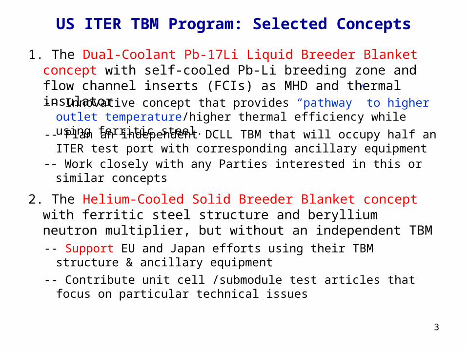
US ITER TBM Program: Selected Concepts
1. The Dual-Coolant Pb-17Li Liquid Breeder Blanket concept with self-cooled Pb-Li breeding zone and flow channel inserts (FCIs) as MHD and thermal insulator-- Innovative concept that provides “pathway” to higher outlet
temperature/higher thermal efficiency while using ferritic steel.
-- Plan an independent DCLL TBM that will occupy half an ITER test port with corresponding ancillary equipment
2. The Helium-Cooled Solid Breeder Blanket concept with ferritic steel structure and beryllium neutron multiplier, but without an independent TBM-- Support EU and Japan efforts using their TBM structure & ancillary
equipment
-- Contribute unit cell /submodule test articles that focus on particular technical issues
-- Work closely with any Parties interested in this or similar concepts

4
A Detailed TBM Planning and Costing Activity for the US TBM Program has been requested by the DOE
Planning will be for the US Reference Scenarios: – DCLL TBM with PbLi exit temperature of 470ºC and a series of TBM
that occupy half a port.– HCCB submodule that has a size of 1/3 of one-half port in cooperation
with the EU or Japan Detailed planning and cost is for a 10 year period between now and
the shipment of the TBM deliverables in 2015 for DAY ONE ITER operation.
The cost is the total cost for the TBM project including R&D, design, engineering, fabrication, qualification, etc., as well as the cost of interface with ITER and other parties.
The R&D Cost includes all costs related to the Reference Scenarios that occur within the next 10 year period whether they are related to the first (Day ONE) Test Articles or subsequent test articles.
Cost of the deliverables includes only the cost of the First Test Article and associated equipment (See Project Deliverables slide).

5
US Test Blanket “Project” Deliverables Based on Reference Scenario Parameters
US DCLL– Test Module
– Helium Flow Loop (primary)
– PbLi Flow Loop
– Tritium Processing Systems
– Secondary Helium Flow Loop (and Heat Exchanger for PbLi Flow Loop)
US HCCB– Test Submodule
– Ancillary Equipments (primary helium flow conditioners, measuring systems for helium, tritium, and test submodule)
Pb-Li Primary Coolant LoopTransporter, Port Cell Area
Secondary He Coolant Loop
TCWS
Test PortPrimary He Coolant
LoopTCWS
DCLL TBM coolant circuits, Red-doted circuit shows the primary He loop cooling the first wall and all FS structures, Blue-dash circuit shows the Pb-Li loop and the Green-dash circuit shows the secondary helium loop.

6
US ITER TBM Costing Activity Milestones
12-Aug-05 Costing Activity Initiated 31-Aug-05 WBS established for Level 6 and lower Responsible persons for Level 6 and lower assigned 7-Sep-05 WBS for Level 6 and lower revised 9-Sep-05 Conceptual design summaries for DCLL and HCCB
issued 6-Oct-05 Initial schedule and base cost estimate for
WBS level 6 of DCLL and HCCB 27-Oct-05 Initial schedule and base cost estimate for
engineering design, procurement/fabrication, and ancillary equipment
7-Nov-05 R&D decision criteria established 30-Nov-05 Complete revised schedule and cost estimate for WBS level 6
and lower (include contingency factor) 12-14 Dec-05 “Physical” Meeting (all information about costing will be presented
and discussed) 16-Dec-05 R&D priorities finalized 13-Jan-06 Initial Draft Costing Activity Report Due 15-Feb-06 Complete Draft of Final Costing Activity Report 22-23 Feb-06 Physical meeting (internal review of draft report) 1-Mar-06 Complete incorporating comments into the Report 15-Mar-06 Send Final TBM Cost Estimate Report to DOE 28-Mar-06 “External” review

7
US DCLL TBM Reference Scenario Conditions
TBM Reference ScenarioFS Tmax ≤ 550° C
FS/PbLi < 500° C SiC/PbLi < 500° C SiC Tmax < 500° C
He < 450° C PbLi ≤ 470° C
Module Geometry:
Port frame thickness, mm 200
“Dog leg” width, mm 30
Frame and TBM gap width, mm 20
TBM height, m 1.66
TBM width, m 0.484
Radial depth, m 0.413
Frontal area, m2 0.803
First wall shape flat
Module Materials:
Structural material Ferritic Steel (FS), e.g. F82H or EUROFER
Breeding material Pb-17Li
FW/structural coolant 8 MPa helium
Intermediate loop coolant 8 MPa helium
Flow channel insert SiCf /SiC or metallic
sandwich e.g. FS/Al2O3
FW coating 2 mm Be
Notes: DCLL features will be tested at PbLi
temperatures compatible with ferritic steel (500C). He and PbLi flowrate, and inlet and outlet temperature, will be varied depending on experiment underway, but these limits will not be exceeded
External piping material for Helium system will be austenitic steel (transition element required)
External piping material for the PbLi has not yet been decided, but likely to be a commercial ferritic/martensitic steel up to the HX (Cutting/rewelding technique required)
8
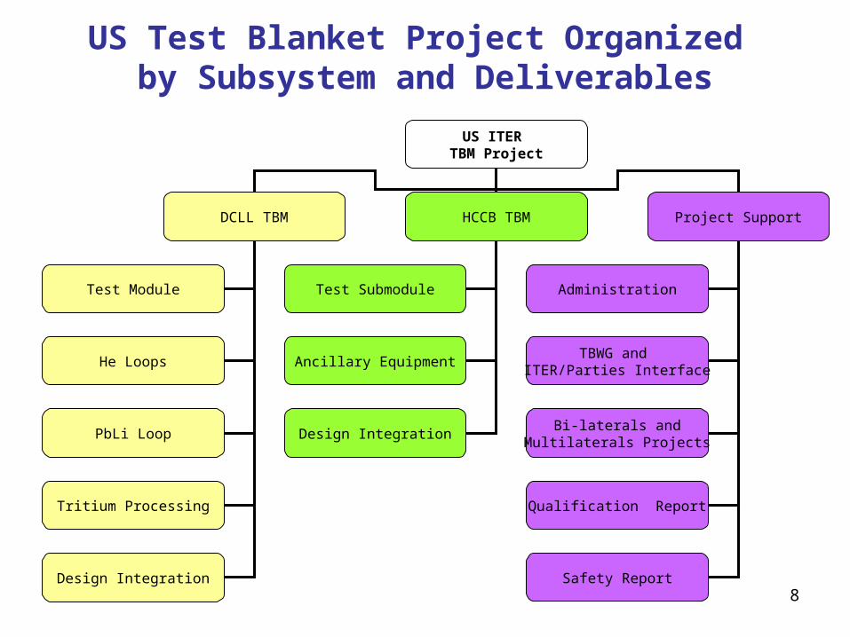
US ITER TBM Project
DCLL TBM HCCB TBM Project Support
Test Module
He Loops
PbLi Loop
Tritium Processing
Design Integration
Test Submodule
Ancillary Equipment
Design Integration
Administration
TBWG and ITER/Parties Interface
Bi-laterals andMultilaterals Projects
Qualification Report
Safety Report
US Test Blanket Project Organized by Subsystem and Deliverables
9
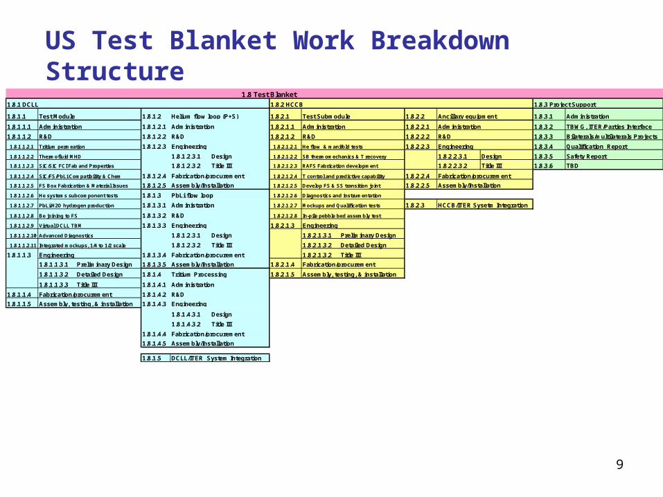
US Test Blanket Work Breakdown Structure
1.8.1.1 Test Module 1.8.1.2 1.8.2.1 1.8.2.2 1.8.3.1
1.8.1.1.1 1.8.1.2.1 Administration 1.8.2.1.1 Administration 1.8.2.2.1 1.8.3.2
1.8.1.1.2 1.8.1.2.2 R&D 1.8.2.1.2 R&D 1.8.2.2.2 1.8.3.3
1.8.1.1.2.1 1.8.1.2.3 1.8.2.1.2.1 1.8.2.2.3 1.8.3.4 Qualification Report
1.8.1.1.2.2 1.8.1.2.3.1 Design 1.8.2.1.2.2 SB thermomechanics & T recovery 1.8.2.2.3.1 Design 1.8.3.5
1.8.1.1.2.3 1.8.1.2.3.2 Title III 1.8.2.1.2.3 RAFS Fabrication development 1.8.2.2.3.2 Title III 1.8.3.6
1.8.1.1.2.4 1.8.1.2.4 1.8.2.1.2.4 T control and predictive capability 1.8.2.2.4
1.8.1.1.2.5 1.8.1.2.5 1.8.2.1.2.5 Develop FS & SS transition joint 1.8.2.2.5
1.8.1.1.2.6 1.8.1.3 1.8.2.1.2.6 Diagnostics and instrumentation
1.8.1.1.2.7 1.8.1.3.1 1.8.2.1.2.7 Mockups and Qualification tests 1.8.2.3 HCCB/ITER Sysetm Integration
1.8.1.1.2.8 1.8.1.3.2 R&D 1.8.2.1.2.8 In-pile pebble bed assembly test
1.8.1.1.2.9 1.8.1.3.3 1.8.2.1.3
1.8.1.1.2.10 1.8.1.2.3.1 Design 1.8.2.1.3.1 Preliminary Design
1.8.1.1.2.11 Integrated mockups, 1/4 to 1/2 scale 1.8.1.2.3.2 Title III 1.8.2.1.3.2 Detailed Design
1.8.1.1.3 1.8.1.3.4 1.8.2.1.3.2 Title III
1.8.1.1.3.1 Preliminary Design 1.8.1.3.5 1.8.2.1.4
1.8.1.1.3.2 Detailed Design 1.8.1.4 1.8.2.1.5
1.8.1.1.3.3 Title III 1.8.1.4.1
1.8.1.1.4 1.8.1.4.2 R&D
1.8.1.1.5 1.8.1.4.3
1.8.1.4.3.1 Design
1.8.1.4.3.2 Title III
1.8.1.4.4
1.8.1.4.5
1.8.1.5 DCLL/ITER System Integration
Engineering
Fabrication/procurement
Assembly/Installation
Fabrication/procurement
PbLi flow loop
Administration
Assembly/Installation
Tritium Processing
Safety Report
TBD
Helium flow loop (P+S)
Engineering
Bilaterals/multilaterals Projects
He flow & manifold tests
Advanced Diagnostics
Engineering
Fabrication/procurement
Assembly, testing, & installation
He systems subcomponent tests
PbLi/H2O hydrogen production
Be joining to FS
Virtual DCLL TBM
Administration
R&D
Tritium permeation
FS Box Fabrication & Material Issues
1.8 Test Blanket 1.8.1 DCLL 1.8.2 HCCB
Administration
Assembly/Installation
Ancillary equipment
Administration
R&D
Engineering
Test Submodule
Fabrication/procurement
Assembly, testing, & installation
Engineering
Fabrication/procurement
Engineering
Assembly/Installation
Fabrication/procurement
Thermofluid MHD
SiC/SiC FCI Fab and Properties
SiC/FS/PbLi Compatibility & Chem
1.8.3 Project Support
Administration
TBWG, ITER/Parties Interface

10
Most Work Breakdown Structure Elements are further broken down into the following subcategories:
Administration R&D Engineering
Preliminary Design Detailed Design Fabrication Support
Fabrication/procurement
Assembly, testing, & installation

11
US strategy for ITER testing of the DCLL Blanket and First Wall Concept
Develop and deploy a series (~4) of vertical half-port DCLL-TBMs during the period of the first 10 years of ITER operation with– Test articles from day one of ITER operation with specific testing
goals and diagnostic systems– Associated ancillary equipment systems
• in a transporter behind the bioshield and in space in the TCWS and tritium buildings
• using bypass PbLi flow to keep temperature of ancillary equipment below material limits
Develop international collaboration on PbLi systems to the maximal extent
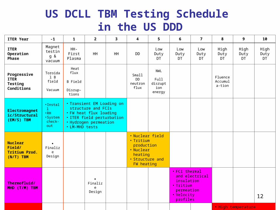
12
US DCLL TBM Testing Schedule in the US DDD
ITER Year -1 1 2 3 4 5 6 7 8 9 10
ITEROperation Phase
Magnet testing & vacuum
HH-First
PlasmaHH HH DD
LowDutyDT
LowDutyDT
LowDutyDT
High DutyDT
High DutyDT
HighDutyDT
ProgressiveITERTesting Conditions
Toroidal B field
Vacuum
Heat flux
B Field
Disrup-tions
Small DD neutron
flux
NWL
Full disruption
energy
FluenceAccumula
-tion
Electromagnetic/Structural (EM/S) TBM
• Install• RH• System check-out
• Transient EM Loading on structure and FCIs
• FW heat flux loading• ITER field perturbation• Hydrogen permeation• LM-MHD tests
Nuclear Field/ Tritium Prod.(N/T) TBM
FinalizeDesign
• Nuclear field • Tritium production• Nuclear heating• Structure and FW
heating
Thermofluid/ MHD (T/M) TBM
FinalizeDesign
• FCI thermal and electrical insulation
• Tritium permeation• Velocity profiles
Integrated (I)TBM
FinalizeDesign
• High temperature effects in TBM
• Tritium permeation/recovery• Integrated function, reliability
13
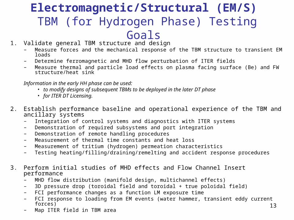
Electromagnetic/Structural (EM/S) TBM (for Hydrogen Phase) Testing Goals
1. Validate general TBM structure and design – Measure forces and the mechanical response of the TBM structure to transient EM loads– Determine ferromagnetic and MHD flow perturbation of ITER fields– Measure thermal and particle load effects on plasma facing surface (Be) and FW structure/heat
sink
Information in the early HH phase can be used: • to modify designs of subsequent TBMs to be deployed in the later DT phase • for ITER DT Licensing.
2. Establish performance baseline and operational experience of the TBM and ancillary systems– Integration of control systems and diagnostics with ITER systems– Demonstration of required subsystems and port integration– Demonstration of remote handling procedures– Measurement of thermal time constants and heat loss– Measurement of tritium (hydrogen) permeation characteristics– Testing heating/filling/draining/remelting and accident response procedures
3. Perform initial studies of MHD effects and Flow Channel Insert performance– MHD flow distribution (manifold design, multichannel effects) – 3D pressure drop (toroidal field and toroidal + true poloidal field)– FCI performance changes as a function LM exposure time – FCI response to loading from EM events (water hammer, transient eddy current forces)– Map ITER field in TBM area

14
DCLL Test Module Fabrication Schedule Summary(note: schedules are evolving)
2005 2006 2007 2008 2009 2010 2011 2012 2013 2014 2015
Administration
R&D
Thermofluid & Performance R&D
Fabrication and Properties R&D
Partially Integrated Tests
Engineering
Preliminary Design
Detailed Design
Title III Activities (Fab Support)
TBM Fabrication
Bid Package Contract Award
Material Procurement
Tooling & Processing
Prototype Fabrication
TBM Fabrication
Assembly, Testing, and Installation
Prototype Packaging & Shipping
Prototype Testing
TBM QA Tests
TBM Packing and Shipping
TBM Assembly & Port Integration
DCLL Test Module Schedule
First plasmaQualification Criteria Safety Dossier
TBMExperiment Execution
Permission to Install
TBMExperiment Execution
*Prototype may or may not be full scale
15
Purposes of R&D activities in a “project” are to reduce risk
Risk that the experimental device will negatively impact ITER – plant safety, licensing– operation schedule
Risk that TBM experiments will not achieve experimental mission– Understanding of phenomena and modeling capability is
insufficient to interpret or utilize data– Failures in diagnostics or large inaccuracies in measurements
give incomplete or poor data– Unanticipated system performance leads to irrelevant or
unquantifiable operating conditions

16
Main DCLL TBM R&D Areas Identified in the US Activity. Several are common issues of interest to all Parties
Test Module R&D Tasks Areas(some have several subtasks)
US Person – Morley
Tritium Permeation Merrill
Tritium Extraction (PbLi & He) Willms
Thermofluid MHD Smolentsev
SiC/SiC Fab Process & Properties Katoh
SiC/PbLi/FS Compatibility Pint
FS Box Fabrication & Material Issues Rowcliffe/Kurtz
Helium Flow Distribution and HX Wong
PbLi/H20 Hydrogen Production Merrill
Be Joining to FS Zinkle/Ulrickson
Virtual TBM Simulation Suite Abdou
Advanced Diagnostics Morley
Integrated mockup tests Ulrickson/Tanaka

17
DCLL Test Module R&D Schedule Summary(note: schedules and R&D tasks are evolving)
2005 2006 2007 2008 2009 2010 2011 2012 2013 2014 2015
Administration
R&DTritium Permeation/Control
Thermofluid MHD
SiC/SiC Fab Process & Properties
SiC/FS/PbLi Compatibility
FS Fabrication & Material Issues
Helium Systems Subcomponent Test
PbLi/H2O Hydrogen Production
Be joining to FS and TBM PFC
Virtual DCLL TBM
Advanced Diagnostics
Integrated mockups, 1/4 to 1/2 scale
Engineering Preliminary Design
Detailed Design
TBM Fabrication (Bid Completion)Prototype
1st TBM
Assembly, Testing, and InstallationPrototype Testing
TBM (QA Testing Installation)
DCLL Test Module Schedule
First plasmaQualification Criteria Safety Dossier
TBMExperiment Execution
Permission to Install
TBMExperiment Execution
18
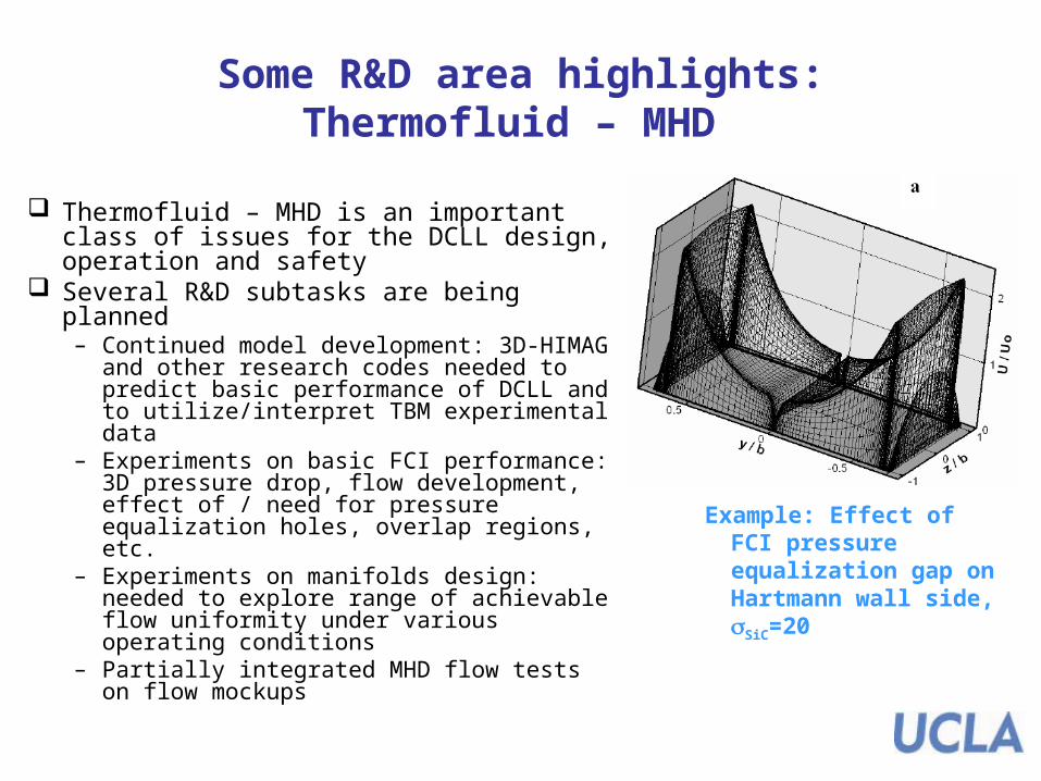
Some R&D area highlights: Thermofluid – MHD
Thermofluid – MHD is an important class of issues for the DCLL design, operation and safety
Several R&D subtasks are being planned– Continued model development: 3D-HIMAG
and other research codes needed to predict basic performance of DCLL and to utilize/interpret TBM experimental data
– Experiments on basic FCI performance: 3D pressure drop, flow development, effect of / need for pressure equalization holes, overlap regions, etc.
– Experiments on manifolds design: needed to explore range of achievable flow uniformity under various operating conditions
– Partially integrated MHD flow tests on flow mockups
Example: Effect of FCI pressure equalization gap on Hartmann wall side, SiC=20

19
Some R&D area highlights: Tritium Inventory and Permeation Modeling
Simulations have lead to a new strategy for tritium control
1. Swept secondary containment around transporter cask and TCWS skid for controlling leaked or permeated tritium
2. More aggressive permeator development to reduce tritium partial pressure in PbLi
3. Swept secondary containment around all PbLi (and He) piping
4. Operation at lower He/PbLi temperatures if ITER limit is approached
Concentric pipe(FS walls)
PermeatorPb-17Li core
PbLi/He HX
Non-Hartmann Gaps
Hartmann Gaps
First wall
Second wall
Rib wallsBack plate
First wall He
Rib HeHe pipes(FS walls)
He/H2O HXs
0 10 20 30 40 500.0
0.5
1.0
1.5
2.0
Trit
ium
pre
ssu
re a
bo
ve P
bL
i (P
a)
Number of pulsesTMAP model and resultant
tritium pressure for an example DCLL case
20
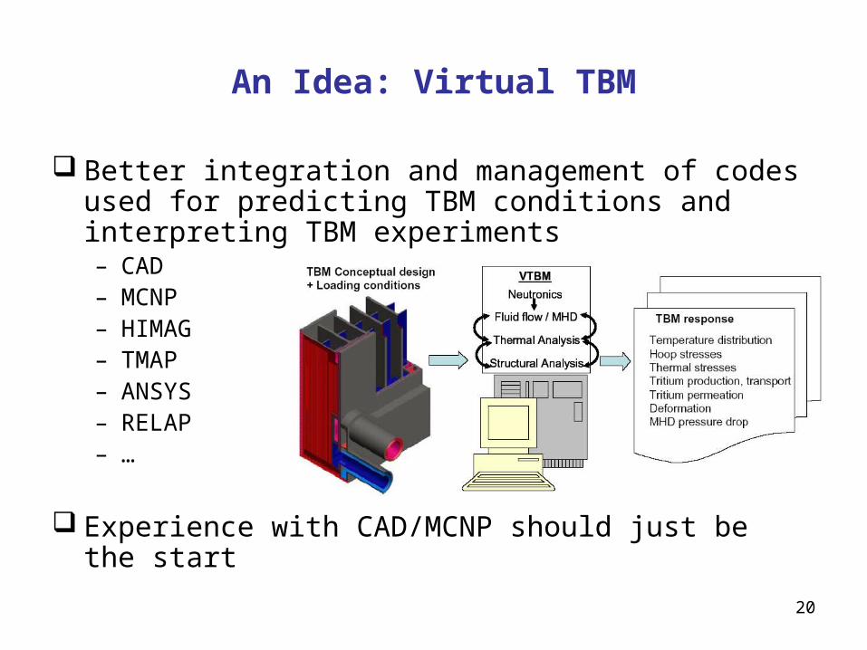
An Idea: Virtual TBM
Better integration and management of codes used for predicting TBM conditions and interpreting TBM experiments– CAD– MCNP– HIMAG– TMAP– ANSYS– RELAP– …
Experience with CAD/MCNP should just be the start
21
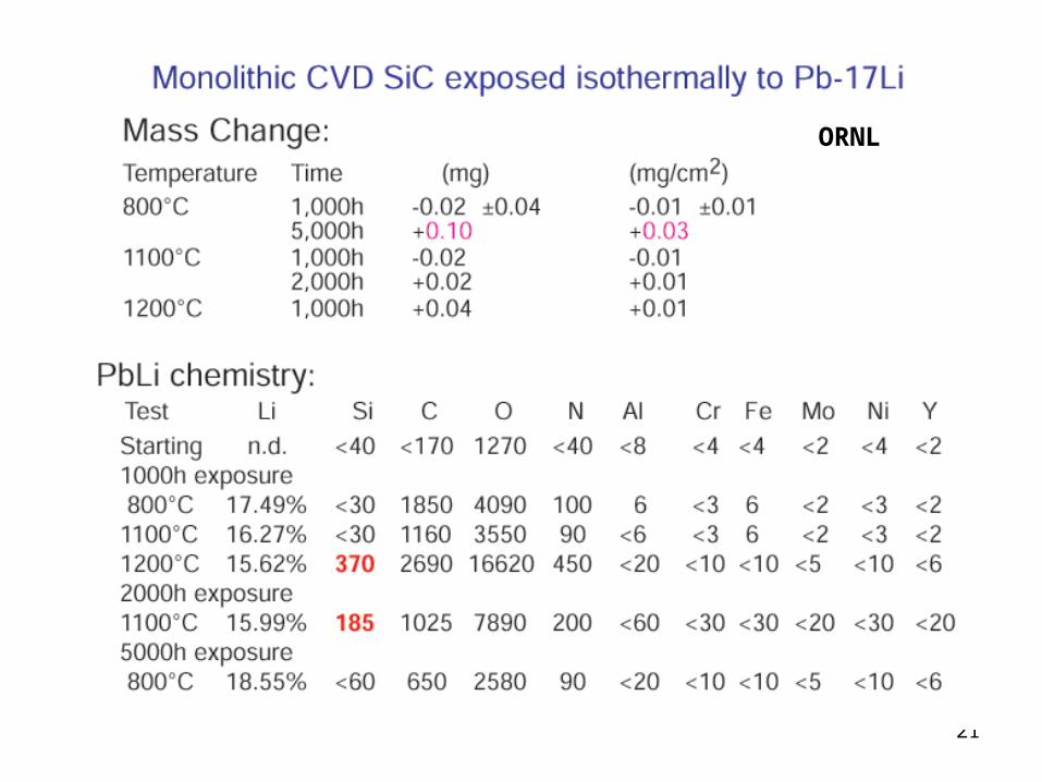
ORNL
22
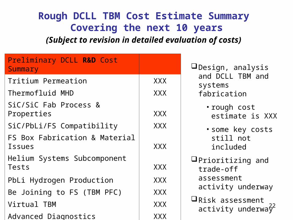
Rough DCLL TBM Cost Estimate Summary Covering the next 10 years
(Subject to revision in detailed evaluation of costs)
Preliminary DCLL R&D Cost Summary
Tritium Permeation XXX
Thermofluid MHD XXX
SiC/SiC Fab Process & Properties XXX
SiC/PbLi/FS Compatibility XXX
FS Box Fabrication & Material Issues XXX
Helium Systems Subcomponent Tests XXX
PbLi Hydrogen Production XXX
Be Joining to FS (TBM PFC) XXX
Virtual TBM XXX
Advanced Diagnostics XXX
Integrated mockup tests XXX
Design, analysis and DCLL TBM and systems fabrication
• rough cost estimate is XXX
• some key costs still not included
Prioritizing and trade-off assessment activity underway
Risk assessment activity underway
23
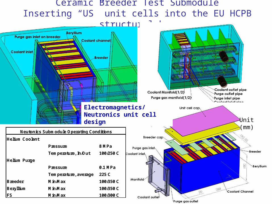
Ceramic Breeder Test SubmoduleInserting “US” unit cells into the EU HCPB structural box
Unit (mm)
Electromagnetics/Neutronics unit cell design
Helium Coolant
Pressure 8 MPa
Temperature, In/Out 100/250 C
Helium Purge
Pressure 0.1 MPa
Temperature, average 225 C
Breeder Min/Max 100/350 C
Beryllium Min/Max 100/350 C
FS Min/Max 100/300 C
Neutonics Submodule Operating Conditions

24
Main HCCB Test Sub-Module R&D Areas Identified in the Activity
Test Module R&D Ying
Helium flow distribution and manifold testing Calderoni
Pebble bed thermomechanics and T recovery Calderoni/Katoh
RAFS fabrication development (overlap with US DCLL) Rowcliffe/Kurtz
T-control and predictive capability Ying/Merrill
Development of FS & SS transition element Zinkle/Kurtz
Diagnostics and instrumentation (some overlap with US DCLL) Calderoni
½ scale mockup and qualification tests (some overlap with US DCLL) Tanaka
In-pile pebble bed assembly test Katoh/Calderoni
25
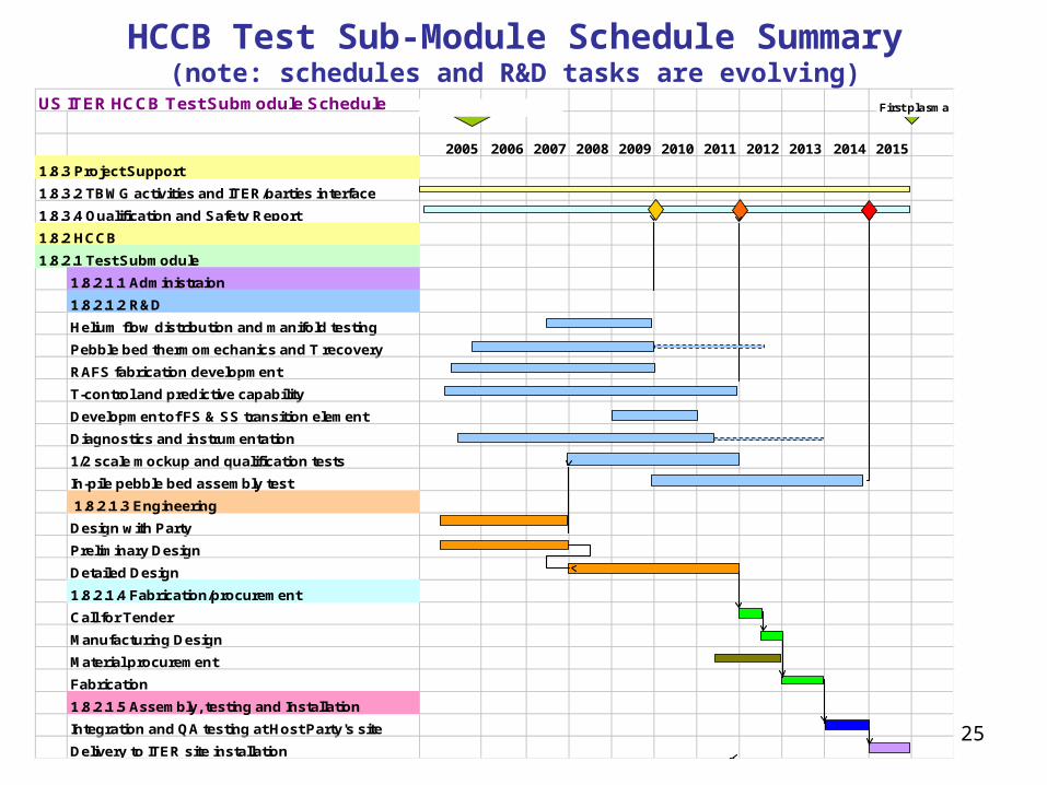
HCCB Test Sub-Module Schedule Summary(note: schedules and R&D tasks are evolving)
US ITER HCCB Test Submodule Schedule
2005 2006 2007 2008 2009 2010 2011 2012 2013 2014 2015
1.8.3 Project Support
1.8.2.1.1 Administraion
1.8.2.1.2 R&D
Helium flow distribution and manifold testing
Pebble bed thermomechanics and T recovery
RAFS fabrication development
T-control and predictive capability
Development of FS & SS transition element
Diagnostics and instrumentation
1/2 scale mockup and qualification tests
In-pile pebble bed assembly test
1.8.2.1.3 Engineering
Design with Party
Preliminary Design
Detailed Design
1.8.2.1.4 Fabrication/procurement
Call for Tender
Manufacturing Design
Material procurement
Fabrication
1.8.2.1.5 Assembly, testing and Installation
Integration and QA testing at Host Party's site
Delivery to ITER site installation
1.8.2.1 Test Submodule
1.8.3.2 TBWG activities and ITER/parties interface
1.8.3.4 Qualification and Safety Report
1.8.2 HCCB
First plasmaITER Director appointed

26
Rough HCCB TBM Cost Estimate Summary Covering the next 10 years
(Subject to revision in detailed evaluation of costs)
Engineering Design Activities: ~$XXX
Fabrication of 1st series of unit cells ~$XXX
1.8.2.1.2 R&D1.8.2.1.2.1 He flow & manifold tests $XXX1.8.2.1.2.2 SB PB thermomechanics & T recovery $XXX1.8.2.1.2.3 RAFS Fabrication development $XXX1.8.2.1.2.4 T control and predictive capability $XXX1.8.2.1.2.5 Develop FS & SS transition joint $XXX1.8.2.1.2.6 Diagnostics and instrumentation $XXX1.8.2.1.2.7 1/2 Scale Mock-ups and Qualification tests $XXX1.8.2.1.2.8 In-pile pebble bed assembly test $XXX
$XXX
1.8.2 HCCB
Subtotal

27
Categorizing R&D Tasks
A system needs to be established to categorize R&D tasks to give a cost range
Simple rating system being tried in the US: E = Essential for the qualification and successful execution of
the TBM experiment, and no other party is doing it I = Important for the qualification and successful execution of
the TBM experiment, or Essential but is definitely being done by another party
D = Desirable but the risk is acceptable if not performed
According to this system: International effort affects US prioritization
28
Some initial conclusions(that some have already realized, but all need to face)
TBMs are generally much more expensive than initial estimates might show– Many hidden expenses will continue to be discovered
– Undefined elements of ITER QA/licensing requirements can impact cost significantly (~>10%)
R&D efforts are a large portion of costs– They must be scrutinized and prioritized
– R&D activities mostly address areas of interest to other Parties
Tested full scale prototypes are likely necessary to avoid failures in first years of operation that jeopardize mission of validating DT phase TBM
There is very little time left if subscale mockups and prototypes are to be attempted.

29
TBWG should identify and coordinate effort on key, common, R&D areas
Suggestion, For each common R&D area, one or two parties (depending on issue difficulty and criticality) should “volunteer” to do the research, and share the results
– Be layer joining to FS – Tritium extraction and cleanup in He purge and coolants– Common diagnostic sensors and controllers– Common test and qualification tests and test facilities– Virtual TBM simulation capabilities– FS technology (joining, shaping, in-situ rewelding, irradiation database)– FS to Austenitic Steel Transition Sections– PbLi/Water hydrogen generation (all PbLi systems with volume > 280 liters)
(Another US Presentation will elaborate on practical possibilities…)
Cooperation on R&D issues is the first step to cooperative test programs – once common needs and purposes are clearly evident to the parties
Related Documents