1 Tutorial 5-1: Part Sketch / Geometric Constraints

Welcome message from author
This document is posted to help you gain knowledge. Please leave a comment to let me know what you think about it! Share it to your friends and learn new things together.
Transcript

1
Tutorial 5-1:
Part Sketch / Geometric Constraints

2
A BRACKET ANALYSIS
• A bracket with a shaft hole– E=210 Gpa, Poison ratio 0.3
– Thickness t=0.1 m
0.15
R0.1
R0.05
0.150.05
FilletR0.02
150kN
100kN
FIXED BC

3
PART MODULE (SKETCH)
• Sketch– Draw outlines of the bottom of the bracket
• Tip– Starting and ending point of a circle
is recognized as a dividing point
– Case 1
– Case 2
Delete the bottom half
Delete the bottom half
One geometric object
Two geometric objects

4
PART MODULE (SKETCH)
• Sketch– Menu/Edit/Auto-Trim, delete half of the outer circle
– Menu/Add/Fillet, add two fillets, radius of those fillets is 0.02
Fillet radius = 0.02
Fillet center point
Add two fillets
Auto trim

5
• Materials– Mechanical, Elasticity, Elastic
– Young’s modulus = 210E9, Poisson’s ratio = 0.3
• Sections– Solid, Homogeneous
– Set plane stress/strain thickness to 0.1 m
• Assign the section to the part
• Assembly, Instance
• Steps– Linear perturbation, Static
PROPERTY / ASSEMBLY / STEPS MODULES

6
• How to apply loads at the center of shaft hole?– Side tool bar/Create a reference point (RP) at the center of the
shaft hole
– Menu/Constraint/Create/MPC Constraint MPC (Multiple point constraints)
– Select the RP as the MPC control point (master node)
– Select the circumference of the hole shaft as the slave nodes
– MPC type select as of Beam
INTERACTION MODULE (MPC)
Reference Point Applied Beam type MPCs

7
• Beam type– Provide a rigid beam between the master node and slave
nodes
– Constraint the “displacement” and “rotation” of the master node to the “displacement” and “rotation” of the slave nodes.
– Distant between the master and slave nodes remain the same
• Pin type– Constraint equal global displacements between the master
node and slave nodes
– Constraint the “displacement” of the master node to the “displacement” of the slave nodes.
MPC Types

8
• Loads– Mechanical, Concentrated force, Uniform,
CF1 = -200kN CF2 = 150kN
• BCs– Step1, ENCASTRE
• Analysis, Create Job, Data Check, Submit
• Results– Max Von Mises 37 MPa
LOADS / JOB / VISUALIZATION MODULES
FIXED BC

9
A BRACKET DESIGN
• A bracket design– Maximum stress is of 50MPa
– Find optimum size of the outer radius (Rout)
– 0.07 m ≤ Rout ≤ 0.1 m
0.15
R0.1
R0.05
0.150.05
FilletR0.02
150kN
100kN
FIXED BC
10
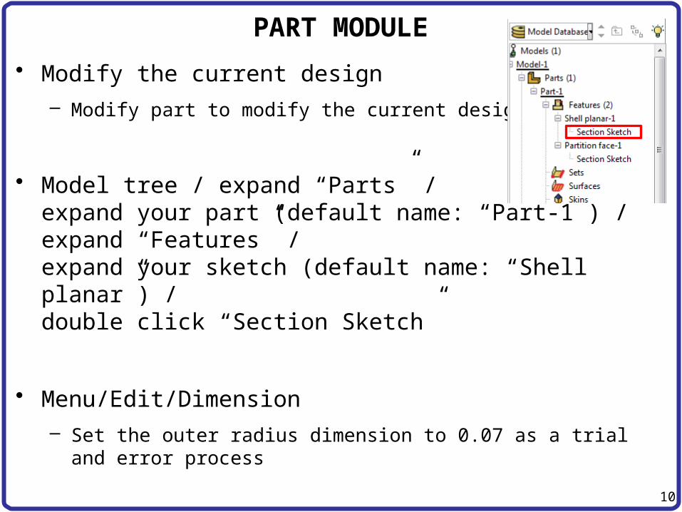
• Modify the current design– Modify part to modify the current design
• Model tree / expand “Parts” /expand your part (default name: “Part-1”) /expand “Features” /expand your sketch (default name: “Shell planar”) /double click “Section Sketch”
• Menu/Edit/Dimension – Set the outer radius dimension to 0.07 as a trial and error
process
PART MODULE
11
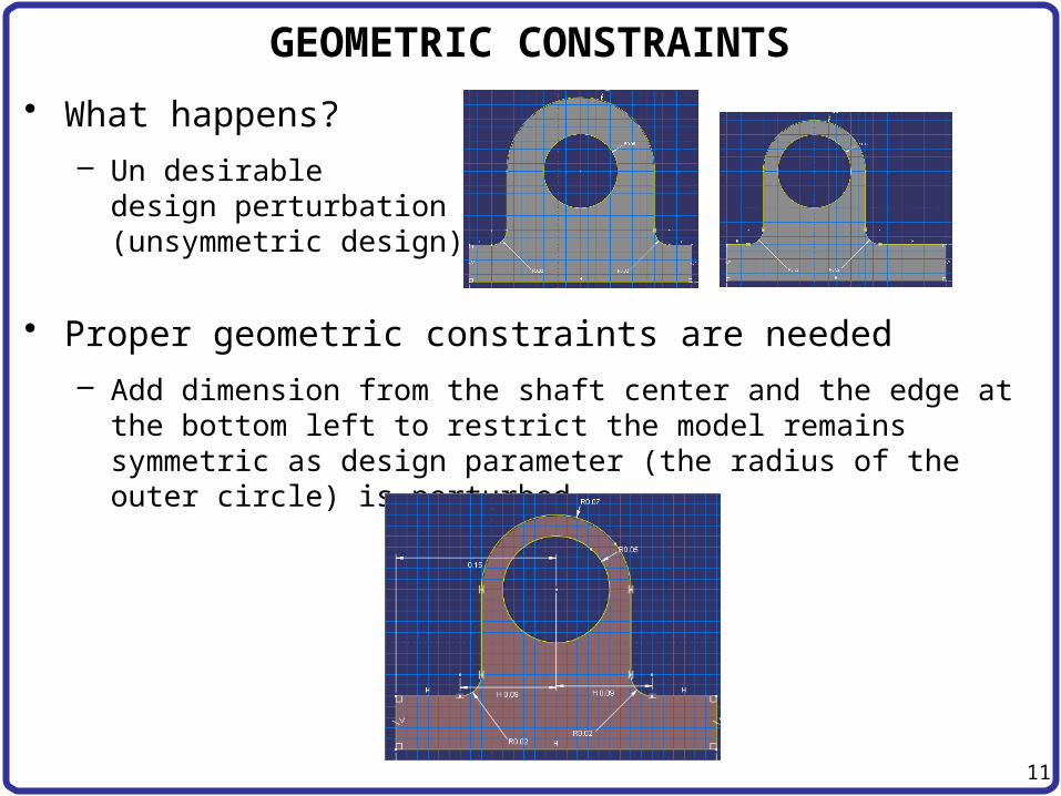
• What happens?– Un desirable
design perturbation(unsymmetric design)
• Proper geometric constraints are needed – Add dimension from the shaft center and the edge at the
bottom left to restrict the model remains symmetric as design parameter (the radius of the outer circle) is perturbed.
GEOMETRIC CONSTRAINTS

12
• After design perturbation– Max Von Mises stress increased to 69 Mpa
(Violation of the maximum stress constraint)
– Repeat the other trials to find optimum design while satisfying the maximum stress constraint
GEOMETRIC CONSTRAINTS

13
Tutorial 5-2:
2D Plane (basic modeling technique)

14
PANEL WITH A HOLE
• A panel with a hole- E = 200 GPa, n=0.3- Thickness t = 0.01 m
2m
5m
50 kPa50 kPa
R=0.25

15
PANEL WITH A HOLE
• E = 200 GPa, n=0.3
• Thickness t = 0.01 m
1m
2.5m
50 kPaR=0.25
U2=UR1=UR3=0 (YSYMM)
U1=UR2=UR3=0(XSYMM)

16
• Parts– 2D Planar, Deformable, Shell, App Size = 10
– Create lines (rectangle): (0, 0), (2.5, 1)
– Create circle (center and perimeter): (0, 0), (0.25, 0)
– Auto trim
• Tip– Even a circle has a starting point and ending point on
circumference
PARTS MODULE

17
• Materials– Mechanical, Elasticity, Elastic
– Young’s modulus = 200E9, Poisson’s ratio = 0.3
• Sections– Solid, Homogeneous
– Set plane stress/strain thickness to 0.01 m
• Assign the section to the part
• Assembly, Instance
• Steps– Linear perturbation, Static
PROPERTY / ASSEMBLY / STEPS MODULES
18
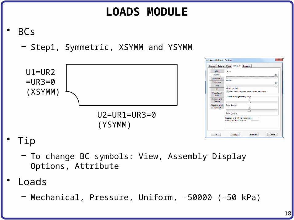
• BCs– Step1, Symmetric, XSYMM and YSYMM
• Tip– To change BC symbols: View, Assembly Display Options,
Attribute
• Loads– Mechanical, Pressure, Uniform, -50000 (-50 kPa)
U2=UR1=UR3=0 (YSYMM)
U1=UR2=UR3=0(XSYMM)
LOADS MODULE

19
MESH MODULE (MESHING TECHNIQUE)
• Structured mesh– Follows predefined mesh patterns (Rule based meshing)
– Predictable mesh shape
– Not applicable for every geometry domain (If geometry domain is not affordable for structured mesh, a warning message and reasons will appear)
– For 2D/Quad-dominated mesh, the geometry domain better have 4 edges
• Free mesh– No predefined mesh patterns
– Flexibility
– Impossible to predict a free mesh pattern

20
MESH MODULE (PARTITION FACE)
• Mesh– Menu: Tool/Partition/Partition Face/Sketch (sketch mode)
– Draw 3 lines
– Menu/Edit/Auto-trim, delete the red line
– Assign Mesh Controls, Quad (Quad only), Structured
– Global seed, size 0.1
0.5m
0.5m
Auto trim
21
MESH MODULE (SEED MESH)
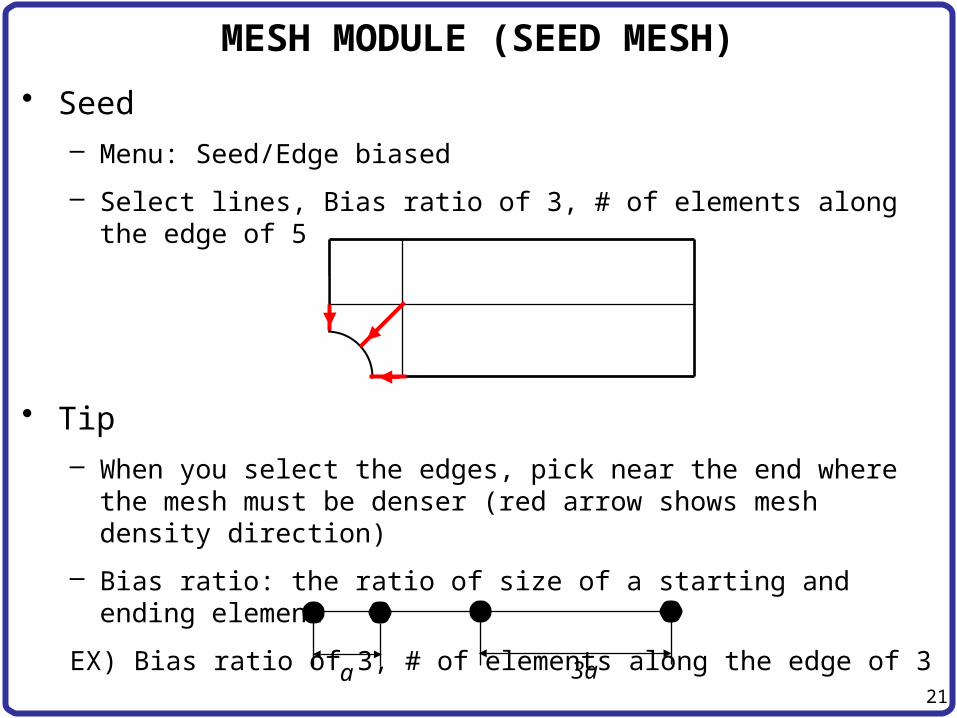
• Seed– Menu: Seed/Edge biased
– Select lines, Bias ratio of 3, # of elements along the edge of 5
• Tip– When you select the edges, pick near the end where the
mesh must be denser (red arrow shows mesh density direction)
– Bias ratio: the ratio of size of a starting and ending element
EX) Bias ratio of 3, # of elements along the edge of 3
a 3a

22
MESH / JOB / VISUALIZATION MODULES
• Seed– Menu: Seed/Edge by number
– Select lines, # of elements along the edge of 5
– Mesh part
• Analysis, Create Job, Data Check, Submit
• Results
• Deformed plot, Stress plots – Field output, Mises
Related Documents


