July 2015 Page 1 of 21 1. THE SPECIFICATION FOR TOPOGRAPHIC SURVEYS The Specification for the topographic surveys is the Environment Agency National Standard Contract and Specification for Surveying, Standard Technical Specifications (Version 3.1). 2. THE SURVEY BRIEF This Survey Brief amplifies and amends the Environment Agency National Standard Contract and Specification for Surveying, Standard Technical Specifications (Version 3.1) and must be read in conjunction with these specifications. Scheme Title: North East Regional Coastal Monitoring Programme Scheme Number: SCB105 Employer’s Address: Scarborough Borough Council, Town Hall, St Nicholas Street, Scarborough, YO11 2HG Nominated Employer’s Representative: Mr Robin Siddle Survey Title: Provision of topographic data for: Work Package TNE01 – Northumberland Frontage Work Package TNE02 – North Tyneside Frontage Work Package TNE03 – South Tyneside Frontage Work Package TNE04 – Sunderland Frontage Work Package TNE05 – County Durham Frontage Work Package TNE06 – Hartlepool Frontage Work Package TNE07 – Redcar & Cleveland Frontage Work Package TNE08 – Scarborough Frontage The Sections of the Standard Technical Specifications which shall apply to this Contract: Section II, Section III, Section VIII Purpose of Survey: The surveys are to be used as part of a long-term programme of coastal monitoring, to analyse coastal processes and provide data for operational and strategic shoreline management. Many of the surveys will be repeated on a regular basis; repeatability is therefore a key requirement. Delivery Schedule: to be in accordance with table 2.5 and section 2.6 Tender Submission Date: See the “Pro Contract System” Contract Completion Date: 31 March 2021 Known Hazards: Scarborough Borough Council is unaware of any special hazards other than those normally associated with beach and cliff surveying. The surveyor shall carry out a full Risk Assessment before each survey and shall prepare a Safe System of Working based on the Assessment. A copy shall be forwarded to the Employer’s Representative. The surveyor’s attention is drawn to the desirability, among other

Welcome message from author
This document is posted to help you gain knowledge. Please leave a comment to let me know what you think about it! Share it to your friends and learn new things together.
Transcript

July 2015 Page 1 of 21
1. THE SPECIFICATION FOR TOPOGRAPHIC SURVEYS
The Specification for the topographic surveys is the Environment Agency National
Standard Contract and Specification for Surveying, Standard Technical Specifications
(Version 3.1).
2. THE SURVEY BRIEF
This Survey Brief amplifies and amends the Environment Agency National Standard
Contract and Specification for Surveying, Standard Technical Specifications (Version
3.1) and must be read in conjunction with these specifications.
Scheme Title: North East Regional Coastal Monitoring Programme
Scheme Number: SCB105
Employer’s Address: Scarborough Borough Council, Town Hall, St Nicholas Street,
Scarborough, YO11 2HG
Nominated Employer’s Representative: Mr Robin Siddle
Survey Title: Provision of topographic data for:
Work Package TNE01 – Northumberland Frontage
Work Package TNE02 – North Tyneside Frontage
Work Package TNE03 – South Tyneside Frontage
Work Package TNE04 – Sunderland Frontage
Work Package TNE05 – County Durham Frontage
Work Package TNE06 – Hartlepool Frontage
Work Package TNE07 – Redcar & Cleveland Frontage
Work Package TNE08 – Scarborough Frontage
The Sections of the Standard Technical Specifications which shall apply to this Contract: Section II, Section III, Section VIII
Purpose of Survey:
The surveys are to be used as part of a long-term programme of coastal monitoring, to analyse coastal processes and provide data for operational and strategic shoreline management.
Many of the surveys will be repeated on a regular basis; repeatability is therefore a key requirement.
Delivery Schedule: to be in accordance with table 2.5 and section 2.6
Tender Submission Date: See the “Pro Contract System”
Contract Completion Date: 31 March 2021
Known Hazards: Scarborough Borough Council is unaware of any special hazards
other than those normally associated with beach and cliff surveying. The surveyor shall
carry out a full Risk Assessment before each survey and shall prepare a Safe System
of Working based on the Assessment. A copy shall be forwarded to the Employer’s
Representative. The surveyor’s attention is drawn to the desirability, among other
July 2015 Page 2 of 21
things, of monitoring the tidal cycle and the weather forecast and of notifying the Coast
Guard of the survey activities.
Site Conditions/Restrictions, Access and Public Relations:
Contact details for any areas requiring specific permission for access will be supplied
to the Contractor. Data layers identifying conservation designations are freely
available from the Natural England website:
http://www.gis.naturalengland.org.uk/pubs/gis/GIS_register.asp.
Due to the sensitivity of over-wintering birds, Natural England prohibit quad bikes from
accessing the following areas during November:
Hartlepool North Beach
Hartlepool North Gare
Redcar Beach.
All surveyors shall carry with them an identification card bearing their photograph and
authorisation, which should be presented as a matter of course and without it being
demanded, at all meetings with landowners or the public.
2.1 GENERAL
2.1.1 Performance Monitoring Arrangements
An annual review will be undertaken by the Employer to examine the performance of
the Contractor during the contract period. If the Contractor is shown to be failing in his
obligations to comply with the terms of the Contract, Specification or Brief, the
Employer may exercise his rights under clause 90 of the Conditions of Contract to
terminate the contract.
2.1.2 Quality Control of Data
The Contractor is responsible for undertaking quality control of the topographic data
to ensure that the data meets the standards and requirements of the Specification and
the Brief. The Employer will undertake QC checks on the processed data within 2
weeks of delivery of each Survey Unit. If data rejected by the Employer requires re-
processing, the re-processed data will be supplied within 1 week of notification of
failure. Survey Units which are rejected due to the survey extent not being complete
(or any other failure to meet the Specification which cannot be corrected by re-
processing) must be re-surveyed within 4 weeks of notification or during the next
suitable tide/weather window. In such cases, in order to maintain data integrity, the
entire Survey Unit must be re-surveyed.
2.1.3 Health & Safety
The Contractor shall comply with all relevant legislation and bylaws when carrying out
the Survey. Equipment and survey personnel provided by the Contractor for work in

July 2015 Page 3 of 21
connection with the contract shall be the Contractor's responsibility at all times. The
said equipment and survey personnel and any loss, injury or damage suffered or
caused by them shall be at the Contractor's risk throughout. All risks of data
acquisition, including equipment hire and demurrage will be borne by the Contractor.
2.2 LOCATION AND EXTENT OF SURVEY
The NE coastline is divided into a series of Work Packages, each sub-divided into a
number of Survey Zones. The location of cross-shore survey profiles, topographic
surveys and cliff monitoring locations are provided in the shapefiles detailed in Table
2.1.
Table 2.1 Accompanying files defining survey extent and other co-ordinates
File name File contents
Cell1_cellone_zones_Aug2015.lyr Shapefile and layer file delineating
Survey Unit boundaries Cell1_cellone_zones_Aug2015.shp
Cell1_topographic_surveys_Aug2015.xlsx Spreadsheet and shapefile of
topographic survey areas. Indicates
frequency, extent and locations of
required surveys. Cell1_topographic_surveys_Aug2015.shp
Cell1_topographic_profiles_start_end_Aug2015.xlsx Spreadsheet and shapefile of Start of
Line/End of Line co-ordinates of profiles Cell1_topographic_profiles_start_end_Aug2015.shp
Cell1_cliff_top_points_locations_Aug2015.xlsx Spreadsheet and shapefile virtual
monitoring points (VMPs) for cliff top
monitoring Cell1_cliff_top_points_locations_Aug2015.shp
Cell1_topographic_line_surveys_Aug2015.xlsx Spreadsheet and shapefile of linear
(alongshore) cliff top and edge of sand
surveys. Cell1_topographic_line_surveys_Aug2015.shp
2.2.1 Location of Survey Lines
Survey profile lines have been defined at varying intervals along the entire North East
coastline. The start and indicative end co-ordinates together with bearings of these
lines are given in the accompanying spreadsheet and GIS files (see Table 2.1, data
provided in Annex A). The Start-of-Line co-ordinates of these profiles is considered as
zero chainage (see Figure 2.1) for all surveys so that profiles obtained from all survey
types (topographic, bathymetric and LiDAR) can be compared. The spreadsheet also
details the timing and frequency of surveys.
2.2.2 Start Point for Survey (the Landward Boundary)
For topographic surveys, the landward boundary to be surveyed (the ‘Start Point’) is
defined as appropriate, by either:
The cliff toe (Figure 2.2)
The landward limit of fixed coastal structure e.g. seawall, embankment (Figure 2.3)
100m inshore from the landward toe of the back barrier toe on a barrier beach (Figure 2.4)
either 200 metres to landward of the seaward face of a dune system or to the back of the dune system if the dunes are less than 200m wide
At agreed locations for any further categories which are identified.

July 2015 Page 4 of 21
Figure 2.1 Definition of terms for topographic survey
Figure 2.2 Start Point at cliff toe
Cliff
Beach
Start of Line
Start Point (landward limit) (seaward
limit)
X
X
X 0 0 + d
Chainage
Start Point
(landward limit
of survey)
Start of Line (for
calculating
chainage) d
X
X

July 2015 Page 5 of 21
Figure 2.3 Start Point for a fixed structure
Figure 2.4 Start Point for barrier beaches
2.2.3 End Point for the Survey (the Seaward Boundary)
The seaward boundary will be dictated by the tidal conditions at the time of the survey.
In as far as is practicable, survey programmes should be scheduled to achieve the
greatest possible extent of foreshore coverage. Ideally, this will be to reach the level
of Mean Low Water Spring tides (MLWS), as defined in Table 2.2. However, it is
recognised that this will not always be practicable across the whole of the North East
coast and therefore survey programming should aim to achieve coverage to the level
of Mean Low Water (MLW) or lower, as defined for each Survey Unit by the Admiralty
tide data (Table 2.2). If coverage to MLW cannot be achieved in a particular Survey
Unit, the Consultant shall discuss with the Employer the extent of coverage that is
possible based on his survey programming for that season’s campaign and agree a
way forward, but in all circumstances coverage to a minimum level of that reached by
Mean Low Water Neap (MLWN) tides will be expected.
Beach
Seawall
0 + d Chainage
X
X
Start Point (landward limit)
(seaward
limit)
X X X
0 0 + d
Start Point (landward limit)
Start of Line
100m minimum
landward limit of beach
Chainage
Barrier
Beach
(seaward
limit)

July 2015 Page 6 of 21
Location MLWN m ODN
MLW (approx.) m ODN
MLWS m ODN
Berwick upon Tweed -1.2 -1.6 -1.9
Holy Island -0.9 -1.4 -1.8
North Sunderland -0.8 -1.3 -1.7
Amble -0.8 -1.3 -1.9
Blyth -0.7 -1.3 -1.8
River Tyne 1.0 -0.1 -1.2
Sunderland -0.7 -1.3 -1.8
Seaham -0.7 -1.4 -2.0
Hartlepool -0.9 -1.4 -1.9
River Tees -0.8 -1.4 -2.1
Whitby -0.8 -1.4 -2.0
Scarborough -1.0 -1.7 -2.4
Filey -0.9 -1.6 -2.3
Bridlington -1.1 -1.7 -2.3
Table 2.2 Tidal Elevations (m ODN)
2.2.4 Location of clifftop surveys Clifftop surveys have been defined at specific locations along the North East coastline.
The purpose of this survey, when repeated over time, is to determine rates of change
along eroding sections of cliff. The clifftop surveys take two forms:
(i) continuous surveys along the line of the cliff edge (clifftop survey – lines) (ii) offset measurements from a fixed Virtual Monitoring Point (VMP) to the cliff
edge along a defined bearing (Clifftop survey – points)
Clifftop survey lines are undertaken at four locations in Northumberland and
Scarborough Borough to define the position of the cliff top:
Church Point Caravan Park near Newbiggin,
Sandy Bay Caravan Park near Cambois
Cambois Bay
Scalby Ness, Scarborough North Bay.
The Start of Line co-ordinates and End of Line co-ordinates are given in the
accompanying spreadsheet “Cell1_topgographic_line_surveys_Aug2015.xls” under
the worksheet tab ‘clifftop lines’ (see Table 2.1). Please see Annex A.
Clifftop survey using Virtual Monitoring Points (VMPs) are recorded at a series of
locations, namely:
Trow Point, South Tyneside
Hendon to Ryhope, Sunderland
Dawdon (near Seaham), County Durham
Staithes, Redcar & Cleveland

July 2015 Page 7 of 21
Robin Hood's Bay, Scarborough Borough
Scarborough South Bay, Scarborough Borough
Cayton Bay, Scarborough Borough
Filey Bay, Scarborough Borough.
Virtual Monitoring Points (VMPs) have been established close to, but set back from,
the edge of cliffs at these locations. A series of offset measurements from these VMPs
to the cliff edge will be undertaken along a pre-determined bearing. The Easting and
Northing of the VMPs and the bearing along which the offset measurement to the cliff
edge will be undertaken are given in the accompanying spreadsheet
“Cell1_cliff_top_point_locations_Aug2015.xls” under the worksheet tab ‘clifftop points’
(see Table 2.1). Please see Annex A.
2.3 SURVEY SCHEDULE Surveys are scheduled to be undertaken twice in each year, once in spring and once in autumn, nominally separated by 6 months. The autumn works are referred to as Full Measures Surveys and include a full set of activities, including all beach profile surveys, beach topographic surveys, clifftop lines and clifftop points. The spring works are referred to as Partial Measures Surveys and include a repeat of a sub-set of surveys, comprising a selection of beach profiles and beach topographic surveys and all clifftop lines and clifftop points.
The Full Measures Surveys Contract will comprise a repeat of all of the existing (pre-
established) surveys identified as being undertaken at an annual frequency (Table
2.3). It is expected that these will usually be undertaken between September and
November in each year. The first Full Measures Survey under the Contract will be in
autumn 2016 and the last will be in autumn 2020, meaning there will five sets of
surveys in total.
Note that due to the sensitivity of over-wintering birds, quad bikes are prohibited from
accessing the following areas during November and therefore surveys should be
completed between September and October:
Hartlepool North Beach
Hartlepool North Gare
Redcar Beach.
The Partial Measures Surveys in each year of the Contract will comprise a repeat of
all of the existing (pre-established) surveys identified in Table 2.3. It is expected that
these will usually be undertaken between March and April in each year. The first Partial
Measures Survey under the Contract will be in spring 2017 and the last will be in spring
2021, meaning there will five sets of surveys in total.
July 2015 Page 8 of 21
There are additional survey requirements at Hartlepool and Spittal Carrs in Newbiggin
Bay:
Once every five years, the beach topographic survey at Hartlepool north is extended across a wider frontage, as shown in the GIS polygons provided in the shape file “Cell1_topographic_surveys_Aug2015.shp”. One extended survey will be required at Hartlepool North Sands/Hartlepool Headland as part of this contract. This is required to be incorporated into the Full Measures survey in autumn 2018
The edge of sand is to be surveyed at Spittal Carrs in Newbiggin Bay as part of the pre-established Newbiggin Bay topographic survey in each Full Measures Survey and in each Partial Measures Survey. This is intended to monitoring any adverse impacts of a nearby beach management scheme on intertidal habitats.
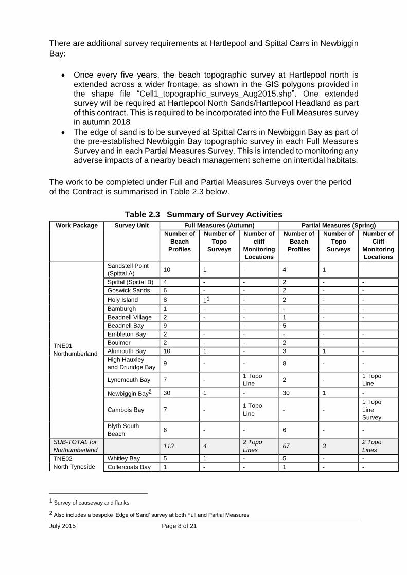
The work to be completed under Full and Partial Measures Surveys over the period of the Contract is summarised in Table 2.3 below.
Table 2.3 Summary of Survey Activities
Work Package Survey Unit Full Measures (Autumn) Partial Measures (Spring)
Number of
Beach
Profiles
Number of
Topo
Surveys
Number of
cliff
Monitoring
Locations
Number of
Beach
Profiles
Number of
Topo
Surveys
Number of
Cliff
Monitoring
Locations
TNE01
Northumberland
Sandstell Point
(Spittal A) 10 1 - 4 1 -
Spittal (Spittal B) 4 - - 2 - -
Goswick Sands 6 - - 2 - -
Holy Island 8 11 - 2 - -
Bamburgh 1 - - - - -
Beadnell Village 2 - - 1 - -
Beadnell Bay 9 - - 5 - -
Embleton Bay 2 - - - - -
Boulmer 2 - - 2 - -
Alnmouth Bay 10 1 - 3 1 -
High Hauxley
and Druridge Bay 9 - - 8 - -
Lynemouth Bay 7 - 1 Topo
Line 2 -
1 Topo
Line
Newbiggin Bay2 30 1 - 30 1 -
Cambois Bay 7 - 1 Topo
Line - -
1 Topo
Line
Survey
Blyth South
Beach 6 - - 6 - -
SUB-TOTAL for
Northumberland 113 4
2 Topo
Lines 67 3
2 Topo
Lines
TNE02
North Tyneside
Whitley Bay 5 1 - 5 - -
Cullercoats Bay 1 - - 1 - -
1 Survey of causeway and flanks
2 Also includes a bespoke ‘Edge of Sand’ survey at both Full and Partial Measures

July 2015 Page 9 of 21
Work Package Survey Unit Full Measures (Autumn) Partial Measures (Spring)
Number of
Beach
Profiles
Number of
Topo
Surveys
Number of
cliff
Monitoring
Locations
Number of
Beach
Profiles
Number of
Topo
Surveys
Number of
Cliff
Monitoring
Locations
Tynemouth
Longsands 3 1 - 3 1 -
King Edward’s
Bay 1 - - 1 - -
SUB-TOTAL for
North Tyneside 10 2 - 10 1 -
TNE03
South Tyneside
Littlehaven
Beach 4 1 - 4 1 -
Herd Sands 5
1
- 3 - -
Trow Quarry
(Including
Frenchman’s
Bay)
4 6 VMPs 4 - 6 VMPs
Marsden Bay 4 - - 2 - -
SUB-TOTAL for
South Tyneside 17 2 6 VMPs 13 1 6 VMPs
TNE04
Sunderland
Whitburn Bay 11 1 - 3 - -
Sunderland
Harbour and
Docks
11 - - - - -
Hendon to
Ryhope
(including
Halliwell Banks)
36 1 35 VMPs 13 - 35 VMPs
SUB-TOTAL for
Sunderland 58 2 35 VMPs 16 - 35 VMPs
TNE05
County Durham
Featherbed
Rocks 1 - - 1 - -
Dawdon and
Seaham 1 - 3 VMPs 1 - 3 VMPs
Blast Beach 3 - - 3 - -
Hawthorn Hive 1 - - 1 - -
Blackhall Colliery 3 - - - - -
SUB-TOTAL for
County Durham 9 - 3 VMPs 6 - 3 VMPs
TNE06
Hartlepool
North Sands and
Headland 73 14 - 7 - -
Middleton 1 1 - 1 - -
Hartlepool Bay 4 1 - 4 - -
North Gare - 1 - - - -
SUB-TOTAL for
Hartlepool 12 4 - 12 - -
TNE07
Redcar and
Cleveland
Coatham Sands 3
1
- 3 - -
Redcar Sands 4 - 4 1 -
Marske Sands 1 - 1 - -
Saltburn Sands 1 - 1 1 -
Cattersty Sands
(Skinningrove) - 1 - - 1 -
3 1cHN1 is in County Durham, but is reported under Hartlepool.
4 Extended survey area once every five years. Next in 2018 – see GIS database
July 2015 Page 10 of 21
Work Package Survey Unit Full Measures (Autumn) Partial Measures (Spring)
Number of
Beach
Profiles
Number of
Topo
Surveys
Number of
cliff
Monitoring
Locations
Number of
Beach
Profiles
Number of
Topo
Surveys
Number of
Cliff
Monitoring
Locations
Staithes5 - - 12 VMPs - - 12 VMPs
SUB-TOTAL for
Redcar and
Cleveland
9 2 12 VMPs 9 3 12 VMPs
TNE08
Scarborough
Staithes6 - - 8 VMPs - - 8 VMPs
Runswick Bay - 1 - - 1 -
Sandsend,
Upgang and
Whitby
3 1 - 3 - -
Robin Hoods Bay - 1 13 VMPs - 1 13 VMPs
Scarborough
North Bay 5 1
1 Topo
Line 5 -
1 Topo
Line
Scarborough
South Bay 4 1 13 VMPs 4 - 13 VMPs
Cayton Bay 4 1 8 VMPs 4 - 8 VMPs
Filey Bay 5 1 28 VMPs 5 1 28 VMPS
SUB-TOTAL for
Scarborough 21 7
70 VMPs
1 Topo
Line
21 3
70 VMPs
1 Topo
Line
GRAND TOTAL 249 23
126 VMPs
3 Topo
Line
154 11
126 VMPs
3 Topo
Line
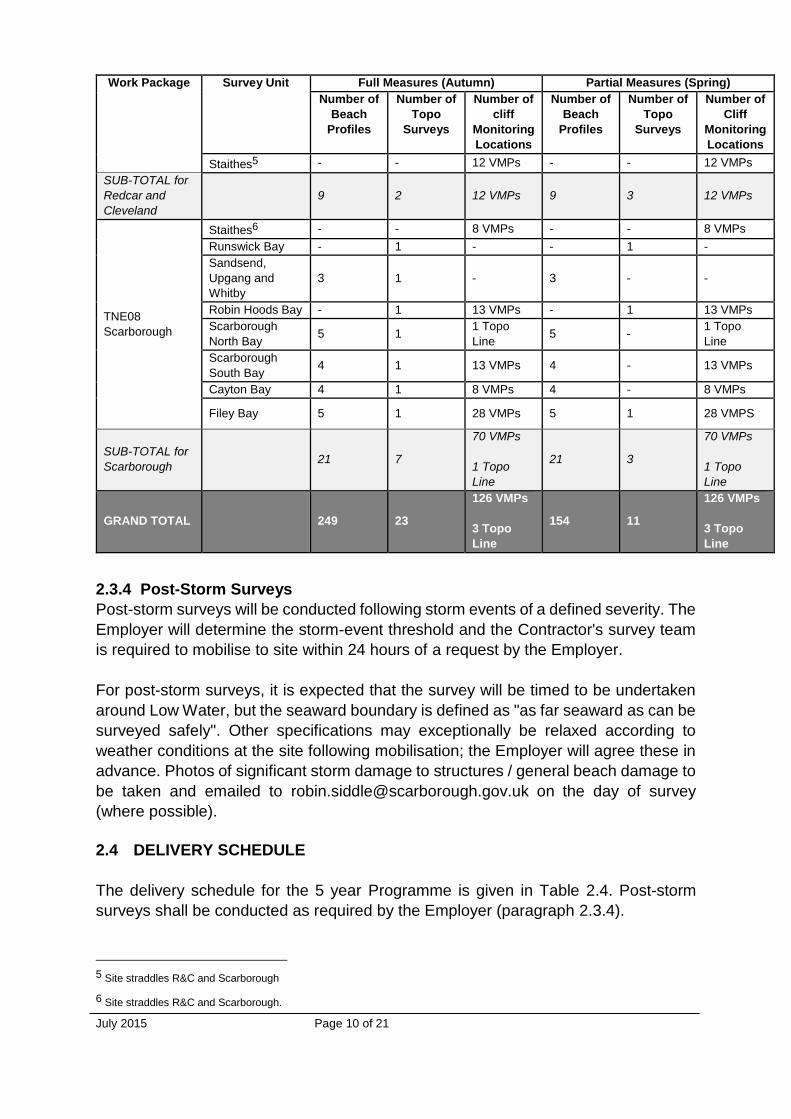
2.3.4 Post-Storm Surveys
Post-storm surveys will be conducted following storm events of a defined severity. The
Employer will determine the storm-event threshold and the Contractor's survey team
is required to mobilise to site within 24 hours of a request by the Employer.
For post-storm surveys, it is expected that the survey will be timed to be undertaken
around Low Water, but the seaward boundary is defined as "as far seaward as can be
surveyed safely". Other specifications may exceptionally be relaxed according to
weather conditions at the site following mobilisation; the Employer will agree these in
advance. Photos of significant storm damage to structures / general beach damage to
be taken and emailed to [email protected] on the day of survey
(where possible).
2.4 DELIVERY SCHEDULE
The delivery schedule for the 5 year Programme is given in Table 2.4. Post-storm
surveys shall be conducted as required by the Employer (paragraph 2.3.4).
5 Site straddles R&C and Scarborough
6 Site straddles R&C and Scarborough.

July 2015 Page 11 of 21
Table 2.4. Delivery schedule of surveys.
Survey type Frequency Working
window Completion blocks Years
Total
surveys
Full Measures Autumn September –
November*
Completion of each
1km block within 2
(daylight) tides
2016 – 2020 5
Partial Measures Spring March - April
Completion of each
1km block within 2
(daylight) tides
2017 - 2012 5
Hartlepool North
Extended Autumn
September –
November*
Completion of each
1km block within 2
(daylight) tides
2018 1
Post-storm As required As required
On-site within 24 hours
of request. Completion
within 2 (daylight) tides
2012-2016 As
required
* note access restrictions due to over-wintering birds at certain beaches.
All Full Measures and Partial Measures surveys shall be completed in 1km blocks (see
section 2.3.1), each block to be completed within 2 (daylight) tides. Post-storm surveys
must start within 24 hours of a request by the Client and must be completed within 2
(daylight) tides.
2.5 TECHNICAL REQUIREMENTS
2.5.1 General Requirements Applicable To All Surveys
Surveys will be required over low water spring tide periods in order to achieve the
required seaward limit of surveys. Surveys will be programmed to ensure that the
required seaward limit can be achieved.
Any survey marks used to identify the first point to be surveyed on each profile line
will be maintained; these will be surveyed on the occasion of each survey and used
to check the results of the survey. The type of markers to be used shall be approved by
the Employer. Wherever possible, markers should be grouted into concrete or other
permanent structures.
All software to be used for survey processing will be agreed in advance. The surveyor
shall provide details of all software packages and survey equipment to be used in the
Method Statement required as part of the tender.
When Kinematic GNSS data collectors are used for profile measurement they will be
set to a horizontal precision of 15mm and a vertical precision of 20mm (Section III, 7.0
Standard Technical Specifications). For alongshore (continuous) data collection,
horizontal precision may be reduced to 50mm and vertical precision to 50mm.
2.5.2 Method of survey
July 2015 Page 12 of 21
The technical details given in this section represent the minimum that shall be
achieved in terms of data coverage and are based on the assumption of RTK GPS as
the survey method. Other methods of survey may be used e.g. laser scanning, ATV
etc., in accordance with the Specification, providing that the minimum requirements
are met. Details shall be provided in the Method Statement to demonstrate that the
Consultant's proposed instrumentation and method of survey can fulfil the minimum
technical requirements.
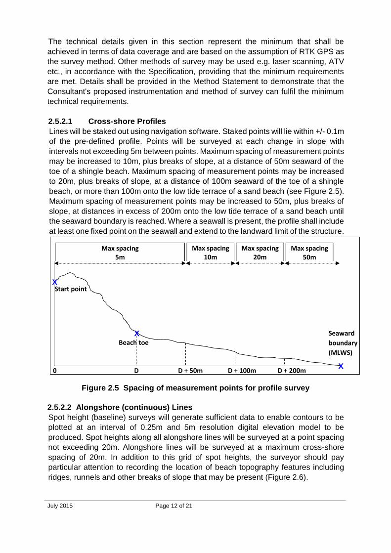
2.5.2.1 Cross-shore Profiles
Lines will be staked out using navigation software. Staked points will lie within +/- 0.1m
of the pre-defined profile. Points will be surveyed at each change in slope with
intervals not exceeding 5m between points. Maximum spacing of measurement points
may be increased to 10m, plus breaks of slope, at a distance of 50m seaward of the
toe of a shingle beach. Maximum spacing of measurement points may be increased
to 20m, plus breaks of slope, at a distance of 100m seaward of the toe of a shingle
beach, or more than 100m onto the low tide terrace of a sand beach (see Figure 2.5).
Maximum spacing of measurement points may be increased to 50m, plus breaks of
slope, at distances in excess of 200m onto the low tide terrace of a sand beach until
the seaward boundary is reached. Where a seawall is present, the profile shall include
at least one fixed point on the seawall and extend to the landward limit of the structure.
Figure 2.5 Spacing of measurement points for profile survey
2.5.2.2 Alongshore (continuous) Lines
Spot height (baseline) surveys will generate sufficient data to enable contours to be
plotted at an interval of 0.25m and 5m resolution digital elevation model to be
produced. Spot heights along all alongshore lines will be surveyed at a point spacing
not exceeding 20m. Alongshore lines will be surveyed at a maximum cross-shore
spacing of 20m. In addition to this grid of spot heights, the surveyor should pay
particular attention to recording the location of beach topography features including
ridges, runnels and other breaks of slope that may be present (Figure 2.6).
X
X Beach toe
Start point
X
Max spacing 20m
Max spacing 50m
Max spacing 10m
Max spacing 5m
D D + 50m D + 100m 0
Seaward
boundary
(MLWS)
D + 200m

July 2015 Page 13 of 21
Figure 2.6 Continuous survey spacing of measurement points (plan view)
2.5.2.3 Post-storm Profile Surveys
In addition to the profile survey requirements, where a seawall is present in the Survey
Unit to be surveyed, a continuous line will be surveyed as close as possible to the
base of seawall. Where a sand dune is present in the Survey Unit to be surveyed, a
continuous line will be surveyed along the toe of the sand dune.
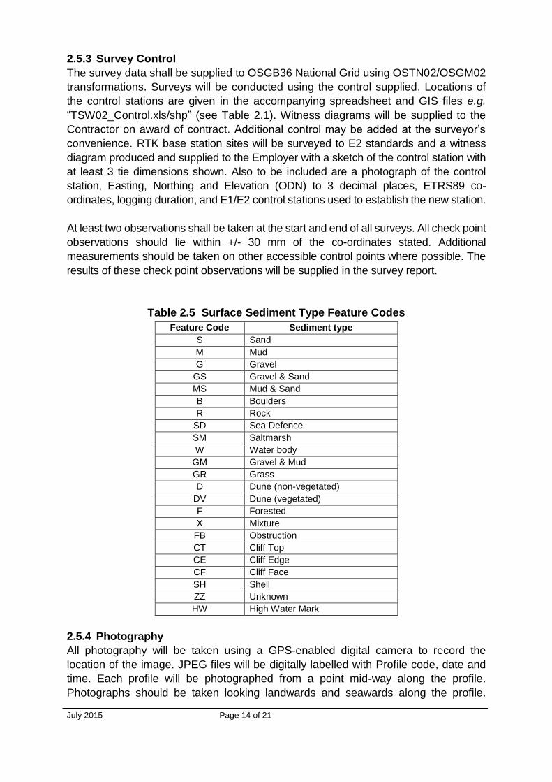
2.5.2.4 Feature Codes
Each measured data point shall be tagged with a Feature Code which represents the
sediment surface type. The only permissible Feature Codes are given in Table 2.5.
Note that the High Water Mark (HW) should only be tagged where the surveyor is
reasonably certain that the High Water Mark represents the maximum run-up elevation
of the previous High Water. Nevertheless, it is a particularly useful measurement for
research into beach behaviour and every effort should be made to identify the High
Water Mark whenever possible, particularly on post-storm surveys. "X" should only be
used for sediment mixtures which cannot be described by GS, MS or GM
Maximum
spacing 20m
Maximum
spacing 20m
Beach topographic
features to be recorded Maximum
spacing 20m
Seaward limit of survey
Landward limit of survey
July 2015 Page 14 of 21
2.5.3 Survey Control
The survey data shall be supplied to OSGB36 National Grid using OSTN02/OSGM02
transformations. Surveys will be conducted using the control supplied. Locations of
the control stations are given in the accompanying spreadsheet and GIS files e.g.
“TSW02_Control.xls/shp” (see Table 2.1). Witness diagrams will be supplied to the
Contractor on award of contract. Additional control may be added at the surveyor’s
convenience. RTK base station sites will be surveyed to E2 standards and a witness
diagram produced and supplied to the Employer with a sketch of the control station with
at least 3 tie dimensions shown. Also to be included are a photograph of the control
station, Easting, Northing and Elevation (ODN) to 3 decimal places, ETRS89 co-
ordinates, logging duration, and E1/E2 control stations used to establish the new station.
At least two observations shall be taken at the start and end of all surveys. All check point
observations should lie within +/- 30 mm of the co-ordinates stated. Additional
measurements should be taken on other accessible control points where possible. The
results of these check point observations will be supplied in the survey report.
Table 2.5 Surface Sediment Type Feature Codes
Feature Code Sediment type
S Sand
M Mud
G Gravel
GS Gravel & Sand
MS Mud & Sand
B Boulders
R Rock
SD Sea Defence
SM Saltmarsh
W Water body
GM Gravel & Mud
GR Grass
D Dune (non-vegetated)
DV Dune (vegetated)
F Forested
X Mixture
FB Obstruction
CT Cliff Top
CE Cliff Edge
CF Cliff Face
SH Shell
ZZ Unknown
HW High Water Mark
2.5.4 Photography
All photography will be taken using a GPS-enabled digital camera to record the
location of the image. JPEG files will be digitally labelled with Profile code, date and
time. Each profile will be photographed from a point mid-way along the profile.
Photographs should be taken looking landwards and seawards along the profile.

July 2015 Page 15 of 21
Where obstructions or beach conditions cause gaps in the beach or cliff survey, these
will be documented with photographs that shall be included in the survey report.
2.6 DATA MANAGEMENT
Data files will contain all measured data points (control points must be removed).
Survey data shall be in metres, to 3 decimal places. Elevations shall be reference to
Ordnance Datum.
2.6.1 File Names
Filenames shall not contain spaces. Filenames shall include the date of survey:
YYYY is the year of survey (4 digits)
MM is the month of the survey (2 digits)
DD is the day of the survey (2 digits).
Note that if a survey for one Survey Unit spanned two or three consecutive days, the
file date should be the last survey day. However, if the survey of one Survey Unit was
completed in stages with a gap of several days, separate files should be made.
Profile data
Each profile data file shall contain data from one Survey Unit only and be given the
filename:
CCUUU_YYYYMMDDxx.txt
where CC is the Coastal Process Sub-Cell (2 digits) e.g. 6b
UUU is the Survey Unit (variable number of characters) e.g. SU16-3
xx indicates the type of survey (see below)
Example: Survey Unit 6bSU16-3, surveyed on 23/24 Sep and 01/02 Oct. The data
should be saved in two files:
6bSU16-3_20100924xx.txt and 6bSU16-3_20101002xx.txt
Baseline (spot height) data
Baseline data shall be split into OS 1km tiles with the filename:
OSOSOS_YYYYMMDDxx.txt
where: OSOSOS is the Ordnance Survey 1km tile name
Example: SY4567_20101002xx.txt
Photographs
Photographs shall be named using the regional profile name and the photo orientation:

July 2015 Page 16 of 21
Cross-shore photographs (portrait format) 6b00021_YYYYMMDD_Up.jpg photo taken seaward of beach toe, looking
landward
6b00021_YYYYMMDD_Dwn.jpg photo taken from landward end of profile,
looking seaward
If alongshore photographs are taken they should have the following format (landscape format), either: 6b00021_YYYYMMDD_N/S/E/W.jpg photo taken from beach toe, looking broadly
north / south / east / west
Raw data
Raw files and unedited data collector files shall be zipped into one file and named:
CCUUUU_YYYYMMDDyy.zip
where yy represents, as appropriate:
tri Trimble project
lei Leica project
ski Ski-pro project
ts Total Station
Example: 6bSU16-3_20100924tri.zip
Report of Survey
Survey reports shall be named according to the Survey Unit e.g.
Report_Topo_CCUUU_YYYYMMDD.pdf
Example: Report_Topo_6bSU16-3_20101002.pdf
Metadata
Accompanying metadata files shall be named:
Meta_Topo_Contractor_YYYYMMDD.xls
Where YYYYMMDD refers to the last survey encompassed by the metadata form.
Example: Meta_Topo_Contractor_20101002.xls
2.6.2 File Formats and Contents
Profile data files
Data files shall be tab-delimited text files, with the file extension *.txt. Add “tp” to the
filename for profiles surveyed as part of baseline surveys (representing topographic
profile). Add “tip” to the filename for interim profiles (representing topographic interim
profile). Data must be in columns, with headers:

July 2015 Page 17 of 21
Easting Northing Elevation_OD Chainage FC Profile Reg_ID
Example: 6bSU16-3_20101002tp.txt
6bSU16-3_20101108tip.txt
Easting Northing Elevation_OD Chainage FC Profile Reg_ID
298140.726 78450.091 -1.937 187.549 S CS1 6b00051
298142.436 78447.610 -2.017 190.563 S CS1 6b00051
298448.213 78951.988 6.595 161.766 D N/A 6b00040
298448.680 78951.443 5.832 162.483 DV N/A 6b00040
The chainage is calculated as distance from the Start-of-Line co-ordinates (as given
in *_ProfileLines.xls). Chainage can be positive or negative depending on which side
of the Start-of-Line co-ordinate the surveyed points lie; landward of the Start-of-Line
co-ordinate is negative and seaward of the Start-of-Line co-ordinate is positive.
Profile is the local name for the profile, Reg_ID is the regional profile name; both are
provided by the Employer with the Start-of-Line co-ordinates. FC is the Feature Code
i.e. sediment type. FC shall be in capital letters.
Post-storm profile data files
As for profile data files, but replacing the suffix "tp" with "tpsp", representing
topographic post-storm profiles.
For the continuous line, surveyed as close as possible to the base of seawall, these
data files must be tab-delimited text files, with the file extension *.txt. File format is as
for baseline data (below), but with the suffix “tstrps” to the filename, representing
topographic structure post-storm.
For the continuous line, surveyed along the toe of a sand dune, these data files must
be tab-delimited text files, with the file extension *.txt. File format is as for baseline
data (below), but with the suffix “tdps” to the filename, representing topographic dune
post-storm.
Baseline (spot height) data files
The files shall be tab-delimited text files, with the file extension *.txt. Add “tb” to the
filename, representing topographic baseline. Data must be in columns, with headers:
Easting Northing Elevation_OD FC
Example: SY4567_20101002tb.txt
Easting Northing Elevation_OD FC
298105.738 78501.381 5.775 SD
298107.340 78499.041 5.841 SD
298115.831 78486.579 0.361 B

July 2015 Page 18 of 21
298117.378 78484.325 -0.138 GS
298119.279 78481.531 -0.376 S
FC is the Feature Code i.e. sediment type. FC shall be in capital letters.
Structure survey data files
As for Baseline data files, but with the suffix “tstr” to the filename, representing
topographic structure.
Profile photographs
Photographs of relevant profiles shall be supplied in jpg format. The minimum digital
photo size will be 800 x 600 pixels for landscape images and 600 x 800 pixels for
portrait images. Where barrier beaches occur, photographs will also be taken from the
highest point of the beach crest looking landward and seaward.
RAW DATA FILES
The Raw Data files shall contain any or all of the following:
Control Station descriptions (*.pdf)
Logged GPS files (system specific)
Vector files (system specific)
Network adjustment & Survey software output files (system specific)
IGS Ephemeris files
Rinex Files for survey period
Processing software statistical reports (system specific)
Raw unedited data collection files (system specific)
Report of survey
A report of survey shall be supplied for each survey, in pdf format. The report shall
contain, as a minimum:
Survey diary
Survey area
Survey type
Survey contractor and personnel
Survey control used
RTK and/or Total Station check observations
Wind speed and direction (estimated, Beaufort Force and compass points e.g. SW F3)
Sea state
Times of Low Water (GMT)
Any additional information pertinent to the survey or for data processing
If surveys of several Survey Units are carried out within a few days, the Contractor has
the option of supplying only one Survey Report, providing it contains all required
information for all surveys. The Report, however, should be copied and renamed
appropriately:
July 2015 Page 19 of 21
Example: Report_Topo_6bSU16-4_20101002.pdf
Report_Topo_6bSU16-5_20101002.pdf
Report_Topo_6bSU16-6_20101002.pdf
These Survey Report files are identical and contain information for all 3 surveys.
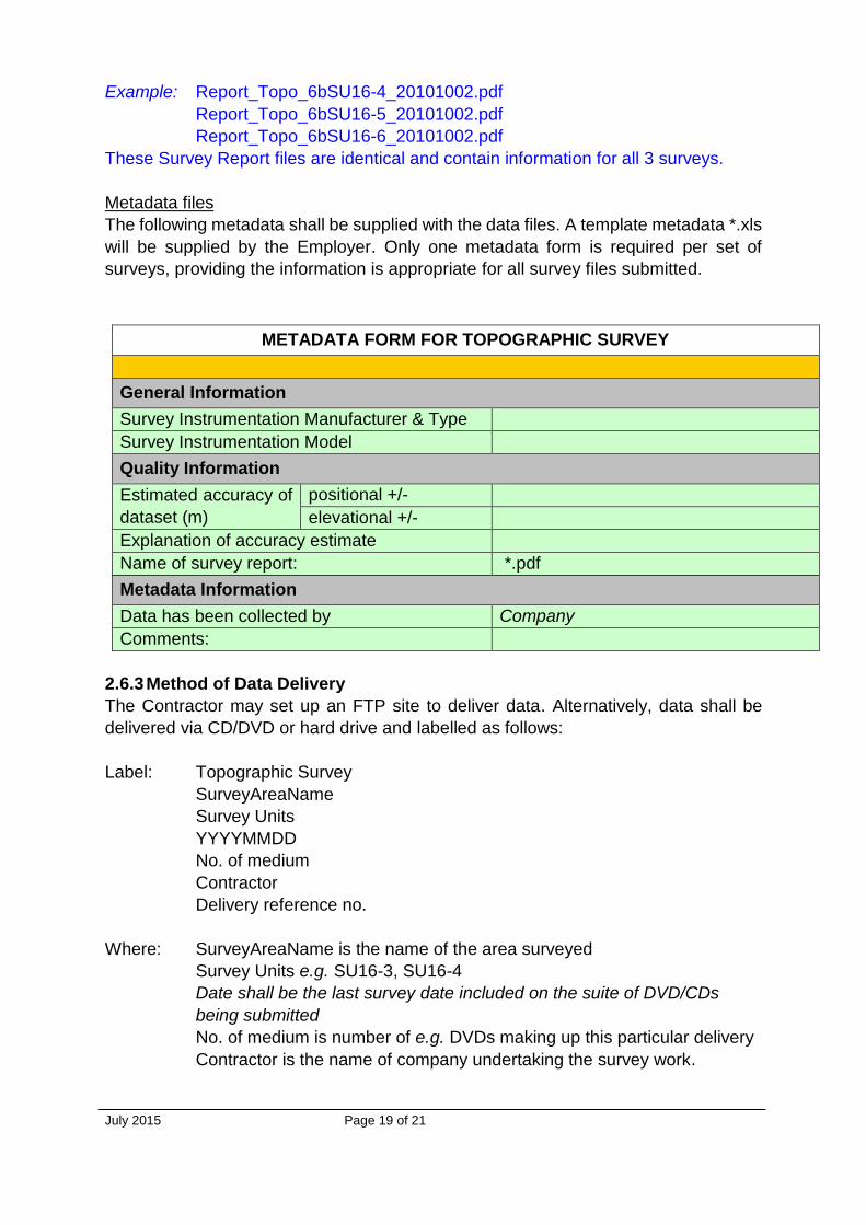
Metadata files
The following metadata shall be supplied with the data files. A template metadata *.xls
will be supplied by the Employer. Only one metadata form is required per set of
surveys, providing the information is appropriate for all survey files submitted.
METADATA FORM FOR TOPOGRAPHIC SURVEY
General Information
Survey Instrumentation Manufacturer & Type
Survey Instrumentation Model
Quality Information
Estimated accuracy of
dataset (m)
positional +/-
elevational +/-
Explanation of accuracy estimate
Name of survey report: *.pdf
Metadata Information
Data has been collected by Company
Comments:
2.6.3 Method of Data Delivery
The Contractor may set up an FTP site to deliver data. Alternatively, data shall be
delivered via CD/DVD or hard drive and labelled as follows:
Label: Topographic Survey
SurveyAreaName
Survey Units
YYYYMMDD
No. of medium
Contractor
Delivery reference no.
Where: SurveyAreaName is the name of the area surveyed
Survey Units e.g. SU16-3, SU16-4
Date shall be the last survey date included on the suite of DVD/CDs
being submitted
No. of medium is number of e.g. DVDs making up this particular delivery
Contractor is the name of company undertaking the survey work.

July 2015 Page 20 of 21
Example: Topographic survey
Dawlish Warren
6bSU16-3,
20110305
CD 1 of 1
Contractor
Delivery Ref. no. 12345
2.7 DELIVERABLES
Processed, quality-controlled survey data shall be delivered within 14 days of
completion of survey of a Survey Unit and in accordance with the survey delivery
schedule (Table 2.4). Final deliverables are (per Survey Unit):
Baseline survey
Profile files (*tp.txt)
Baseline files (*tb.txt)
Structure files (*tstr.txt)
Photographs (*.jpg)
Survey Report (*.pdf)
Raw data files (*.zip)
Metadata (*.xls)
Repeat Baseline survey
Profile files (*tp.txt)
Baseline files (*tb.txt)
Photographs (*.jpg)
Survey Report (*.pdf)
Raw data files (*.zip)
Metadata (*.xls)
Interim profile survey
Profile files (*tip.txt)
Photographs (*.jpg)
Survey Report (*.pdf)
Raw data files (*.zip)
Metadata (*.xls)
Post-storm profile survey
Profile files (*tpsp.txt)
Structure files (*tstrps.txt)
Continuous data file (*tdps.txt)
Photographs (*.jpg)
Survey Report (*.pdf)
Raw data files (*.zip)
Metadata (*.xls)
July 2015 Page 21 of 21
Deliverables shall be sent to Robin Siddle, Scarborough Borough Council, St Nicholas
Street, Scarborough YO11 2HG.
2.8 PAYMENT SCHEDULE
Per Survey Unit
100% on acceptance of data by Employer.
2.9 TENDER INFORMATION
As part of the Method Statement, the Contractor will provide full details to show that
the technical requirements of the Specification and Brief can be met. The Method
Statement shall make reference to:
Health and Safety
Instrumentation to be used
Methodology for survey planning, including how to meet seaward boundaries
Data processing procedures
Quality control procedures
Outline programme for achieving survey within given time frame
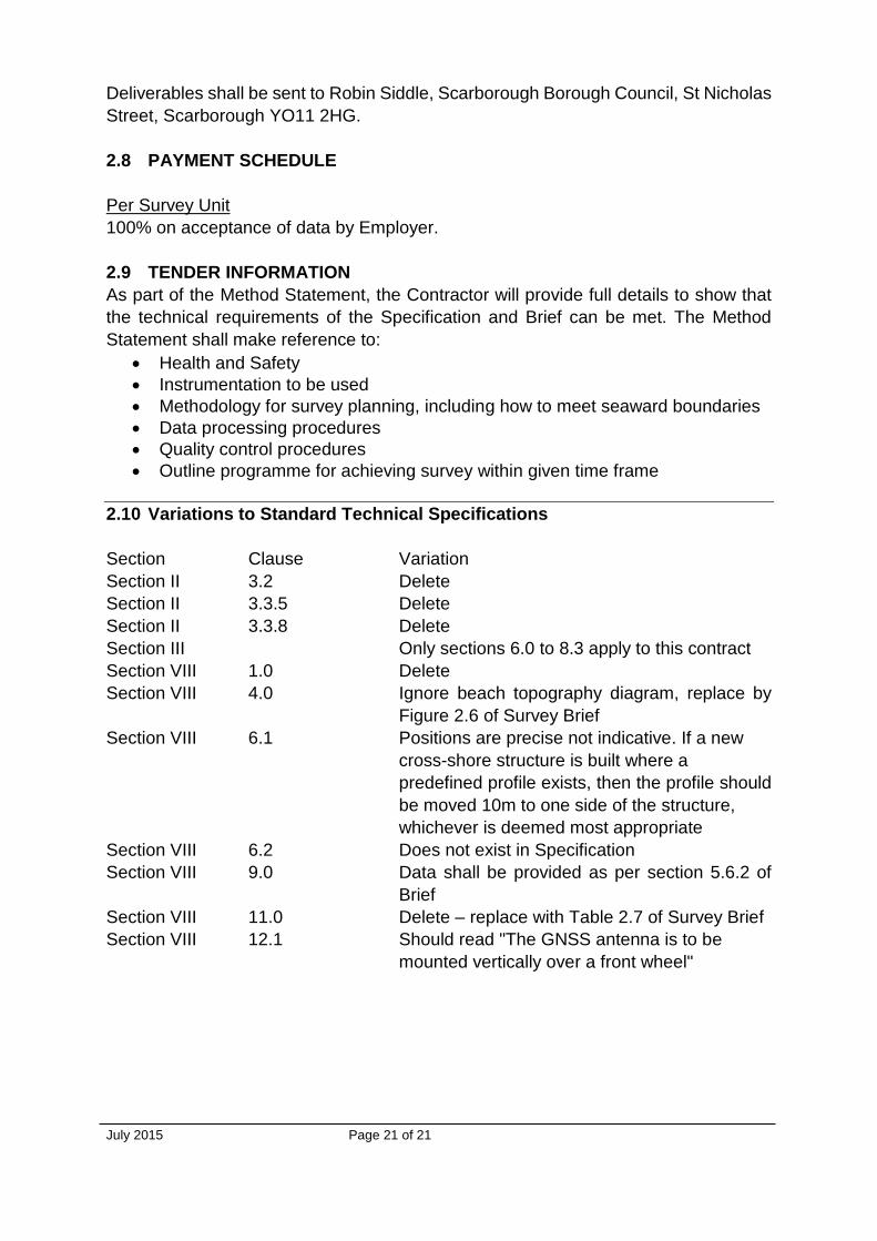
2.10 Variations to Standard Technical Specifications
Section Clause Variation
Section II 3.2 Delete
Section II 3.3.5 Delete
Section II 3.3.8 Delete
Section III Only sections 6.0 to 8.3 apply to this contract
Section VIII 1.0 Delete
Section VIII 4.0 Ignore beach topography diagram, replace by
Figure 2.6 of Survey Brief
Section VIII 6.1 Positions are precise not indicative. If a new
cross-shore structure is built where a
predefined profile exists, then the profile should
be moved 10m to one side of the structure,
whichever is deemed most appropriate
Section VIII 6.2 Does not exist in Specification
Section VIII 9.0 Data shall be provided as per section 5.6.2 of
Brief
Section VIII 11.0 Delete – replace with Table 2.7 of Survey Brief
Section VIII 12.1 Should read "The GNSS antenna is to be
mounted vertically over a front wheel"
Related Documents


