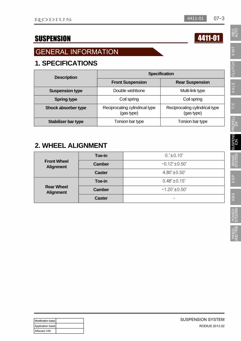
07-3 4411-01 1. SPECIFICATIONS Description Specification Front Suspension Rear Suspension Suspension type Double wishbone Multi-link type Spring type Coil spring Coil spring Shock absorber type Reciprocating cylindrical type (gas type) Reciprocating cylindrical type (gas type) Stabilizer bar type Torsion bar type Torsion bar type 2. WHEEL ALIGNMENT Front Wheel Alignment Toe-in 0.˚±0.10˚ Camber -0.12˚±0.50˚ Caster 4.80˚±0.50˚ Rear Wheel Alignment Toe-in 0.48˚±0.15˚ Camber -1.20˚±0.50˚ Caster -

Welcome message from author
This document is posted to help you gain knowledge. Please leave a comment to let me know what you think about it! Share it to your friends and learn new things together.
Transcript
07-34411-01
1. SPECIFICATIONS
DescriptionSpecification
Front Suspension Rear Suspension
Suspension type Double wishbone Multi-link type
Spring type Coil spring Coil spring
Shock absorber type Reciprocating cylindrical type (gas type)
Reciprocating cylindrical type (gas type)
Stabilizer bar type Torsion bar type Torsion bar type
2. WHEEL ALIGNMENT
Front Wheel Alignment
Toe-in 0.˚±0.10˚
Camber -0.12˚±0.50˚
Caster 4.80˚±0.50˚
Rear Wheel Alignment
Toe-in 0.48˚±0.15˚
Camber -1.20˚±0.50˚
Caster -

07-4
4510-10 Rear stabilizer bar assembly
- Appearance and its link length changed
Stabilizer bar
Stabilizer link
Stabilizer bar
Stabilizer link
4320-01 Rear sub frame module
- Rear sub frame module changed- Front stopper added
4331-01 Camber link
- Apperance changed
4331-06 Tension link
- Apperance changed
3. MAJOR CHANGES
07-54411-01
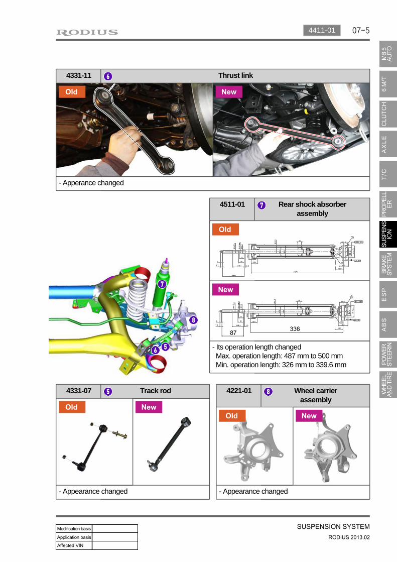
4331-07 Track rod
- Appearance changed
4221-01 Wheel carrier assembly
- Appearance changed
4331-11 Thrust link
- Apperance changed
4511-01 Rear shock absorber assembly
- Its operation length changed Max. operation length: 487 mm to 500 mm Min. operation length: 326 mm to 339.6 mm
07-6
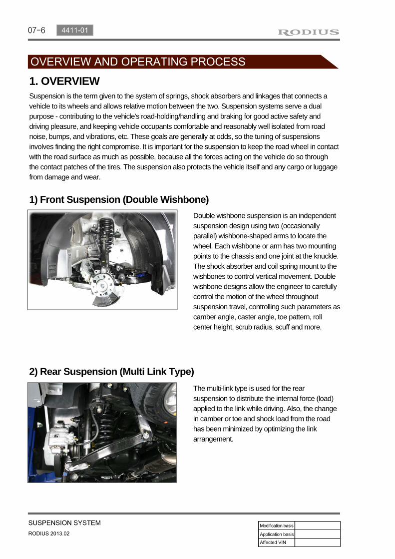
1) Front Suspension (Double Wishbone)
Suspension is the term given to the system of springs, shock absorbers and linkages that connects a vehicle to its wheels and allows relative motion between the two. Suspension systems serve a dual purpose - contributing to the vehicle's road-holding/handling and braking for good active safety and driving pleasure, and keeping vehicle occupants comfortable and reasonably well isolated from road noise, bumps, and vibrations, etc. These goals are generally at odds, so the tuning of suspensions involves finding the right compromise. It is important for the suspension to keep the road wheel in contactwith the road surface as much as possible, because all the forces acting on the vehicle do so through the contact patches of the tires. The suspension also protects the vehicle itself and any cargo or luggage from damage and wear.
2) Rear Suspension (Multi Link Type)
1. OVERVIEW
Double wishbone suspension is an independent suspension design using two (occasionally parallel) wishbone-shaped arms to locate the wheel. Each wishbone or arm has two mounting points to the chassis and one joint at the knuckle. The shock absorber and coil spring mount to the wishbones to control vertical movement. Double wishbone designs allow the engineer to carefully control the motion of the wheel throughout suspension travel, controlling such parameters as camber angle, caster angle, toe pattern, roll center height, scrub radius, scuff and more.
The multi-link type is used for the rear suspension to distribute the internal force (load) applied to the link while driving. Also, the change in camber or toe and shock load from the road has been minimized by optimizing the link arrangement.


07-8
Upper Arm
The upper arm is mounted to the frame and the knuckle and it relieves the load delivered from the tire to the knuckle. This enables to absorb the various impacts according to the load shapes and to ensure the drivability.
Lower Arm
Knuckle
There are two types of knuckle (4WD, 2WD)
Cam bolt
1) Front Suspension (Double Wishbone)
The lower arm is mounted to the knuckle, the shock absorber and the lower arm assembly. It relieves the load delivered from the tire to the knuckle. This enables to absorb the various impacts according to the load shapes and to ensure the drivability.
2. COMPONENTS
07-94411-01
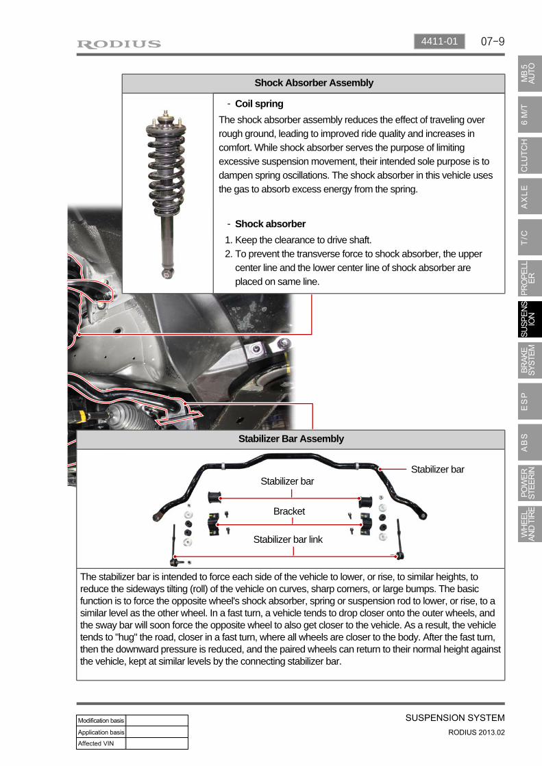
Shock Absorber Assembly
Stabilizer Bar Assembly
The stabilizer bar is intended to force each side of the vehicle to lower, or rise, to similar heights, to reduce the sideways tilting (roll) of the vehicle on curves, sharp corners, or large bumps. The basic function is to force the opposite wheel's shock absorber, spring or suspension rod to lower, or rise, to a similar level as the other wheel. In a fast turn, a vehicle tends to drop closer onto the outer wheels, and the sway bar will soon force the opposite wheel to also get closer to the vehicle. As a result, the vehicle tends to "hug" the road, closer in a fast turn, where all wheels are closer to the body. After the fast turn, then the downward pressure is reduced, and the paired wheels can return to their normal height against the vehicle, kept at similar levels by the connecting stabilizer bar.
Stabilizer barStabilizer bar
Bracket
Stabilizer bar link
Coil spring-
The shock absorber assembly reduces the effect of traveling over rough ground, leading to improved ride quality and increases in comfort. While shock absorber serves the purpose of limiting excessive suspension movement, their intended sole purpose is to dampen spring oscillations. The shock absorber in this vehicle uses the gas to absorb excess energy from the spring.
Shock absorber-
Keep the clearance to drive shaft.To prevent the transverse force to shock absorber, the upper center line and the lower center line of shock absorber are placed on same line.
1. 2.
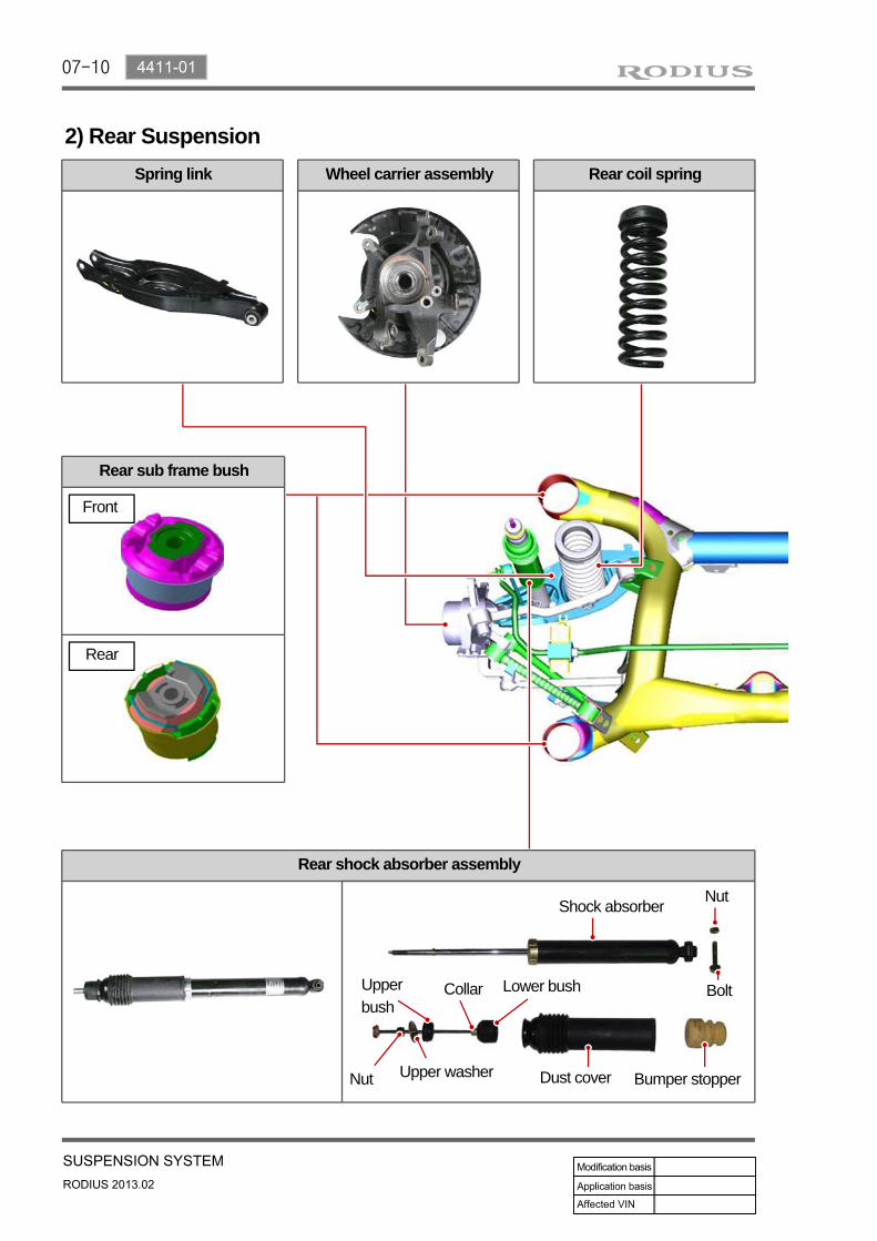
07-10
Spring link
2) Rear Suspension
Rear coil springWheel carrier assembly
Rear sub frame bush
Nut
Upper washer
Upper bush
Bumper stopper
Lower bush
Dust cover
Shock absorber
Bolt
Nut
Collar
Front
Rear
Rear shock absorber assembly
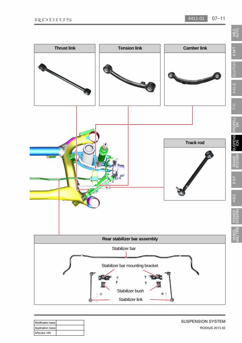
07-114411-01
Thrust link Camber linkTension link
Track rod
Rear stabilizer bar assembly
Stabilizer bar
Stabilizer bar mounting bracket
Stabilizer bush
Stabilizer link

07-12
3. WHEEL ALIGNMENTWheel alignment (adjustment of Camber, Caster and Toe) is part of standard automobile maintenance that consists of adjusting the angles of the wheels so that they are set to the specification. The purpose of these adjustments is to reduce tire wear, and to ensure that vehicle travel is straight and true (without "pulling" to one side). Alignment angles can also be altered beyond the specifications to obtain a specific handling characteristic.
When viewed from the top, the distance between the tire centers is smaller in the front than in
the rear.
▶
Side slip protectionParallel front wheels rotation (straight ahead driving is ensured by toe-in to prevent the wheels from tilting outwards by the camber while driving)Prevention of uneven (outward) tire wear Prevention of toe-out from wearing of steering linkage
- -
-
1) Toe-inThe difference of measured distances between the front ends of the tires (A) and the rear ends of the tires (B) along the same axle when viewed the wheels from the top.
Toe-in Front 0.˚±0.10˚
Rear 0.48˚±0.15˚
Necessity for Wheel Alignment▶
Wheel alignment consists of adjusting the angles of the wheels so that they are perpendicular to the ground and parallel to each other. The purpose of these adjustments is maximum tire life and a vehicle that tracks straight and true when driving along a straight and level road. The symptoms of a vehicle that is out of alignment are:Uneven or rapid tire wearPulling or drifting away from a straight lineWandering on a straight level roadSpokes of the steering wheel off to one side while driving on a straight and level road.
07-134411-01
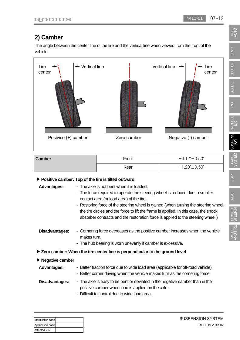
2) CamberThe angle between the center line of the tire and the vertical line when viewed from the front of the vehicle
Camber Front -0.12˚±0.50˚
Rear -1.20˚±0.50˚
Zero camber: When the tire center line is perpendicular to the ground level▶
Disadvantages: The axle is easy to be bent or deviated in the negative camber than in the positive camber when load is applied on the axle.Difficult to control due to wide load area.
-
-
Advantages: Better traction force due to wide load area (applicable for off-road vehicle)Better corner driving when the vehicle makes turn as the cornering force
- -
Negative camber▶
Disadvantages: Cornering force decreases as the positive camber increases when the vehicle makes turn.The hub bearing is worn unevenly if camber is excessive.
-
-
Advantages: The axle is not bent when it is loaded.The force required to operate the steering wheel is reduced due to smaller contact area (or load area) of the tire.Restoring force of the steering wheel is gained (when turning the steering wheel, the tire circles and the force to lift the frame is applied. In this case, the shock absorber contracts and the restoration force is applied to the steering wheel.)
- -
-
Positive camber: Top of the tire is tilted outward▶

07-14
3) CasterThe angle between the vertical line and king pin, which fixes the steering knuckle and front axle, (steering column which connects the top and bottom ball joints in the independent axle type) when viewed the tires from the side.
Caster Front 4.80˚±0.50˚
Rear -
Disadvantages: Impact from the road is transferred to the steering wheel (steering wheel turns)Poor straightness
-
-
Advantages: Directional force to go straight (following control)Restoring force of the wheel (restored to the straight ahead direction)Prevention of wheel shimmy (wheels wobble left and right)
- - -
Negative caster:▶ Top of the king pin is tilted forward from the vertical line of the wheel center when viewed the tires from the side
Positive caster:▶
With considering the height difference between the wheel centers of the front and rear wheels. (Under standard condition that the vehicle is on a level ground)
Caster:▶
Advantages: Smaller turning radius-
Top of the king pin is tilted backward from the vertical line of the wheel center when viewed the tires from the side
Related Documents