1 SA Capstone Requirements and Design Week 5 SYST36367 - Winter 2014 Some slides adapted from: Systems Analysis and Design in a Changing World, 6th Edition, Satzinger, Jackson, Burd, CENGAGE Learning, 2012

1 SA Capstone Requirements and Design Week 5 SYST36367 - Winter 2014 Some slides adapted from: Systems Analysis and Design in a Changing World, 6th Edition,
Dec 30, 2015
Welcome message from author
This document is posted to help you gain knowledge. Please leave a comment to let me know what you think about it! Share it to your friends and learn new things together.
Transcript
1
SA Capstone Requirements and Design
Week 5
SYST36367 - Winter 2014
Some slides adapted from: Systems Analysis and Design in a Changing World, 6th Edition, Satzinger, Jackson, Burd, CENGAGE Learning, 2012

2
Lesson Objectives Build a domain model class diagram
– Brainstorm Technique– Noun Technique
Develop System Sequence Diagrams Build State Diagrams(object behavior)
Deliverable 2 (Project Requirements) due NEXT WEEK!
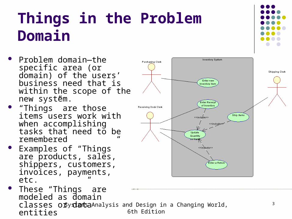
Things in the Problem Domain Problem domain—the specific
area (or domain) of the users’ business need that is within the scope of the new system.
“Things” are those items users work with when accomplishing tasks that need to be remembered
Examples of “Things” are products, sales, shippers, customers, invoices, payments, etc.
These “Things” are modeled as domain classes or data entities
Systems Analysis and Design in a Changing World, 6th Edition 3
Systems Analysis and Design in a Changing World, 6th Edition 4
Systems Analysis and Design in a Changing World, 6th Edition 5
Things in the Problem DomainTwo Techniques for Identifying them
Brainstorming Technique Use a checklist of all of the usual types of things
typically found and brainstorm to identify domain classes of each type
Noun Technique Identify all of the nouns that come up when the
system is described and determine if each is a domain class, an attribute, or not something we need to remember

Systems Analysis and Design in a Changing World, 6th Edition 6
Brainstorming Technique Are there any tangible things? Are there any
organizational units? Sites/locations? Are there incidents or events that need to be recorded?

Systems Analysis and Design in a Changing World, 6th Edition 7
Brainstorming Technique:Steps1. Identify a user and a set of use cases2. Brainstorm with the user to identify things involved
when carrying out the use case—that is, things about which information should be captured by the system.
3. Use the types of things (categories) to systematically ask questions about potential things, such as the following: Are there any tangible things you store information about? Are there any locations involved? Are there roles played by people that you need to remember?
4. Continue to work with all types of users and stakeholders to expand the brainstorming list
5. Merge the results, eliminate any duplicates, and compile an initial list
Systems Analysis and Design in a Changing World, 6th Edition 8
The Noun Technique A technique to identify problem domain classes
(things) by finding, classifying, and refining a list of nouns that come up in in discussions or documents
Popular technique. Systematic. Does end up with long lists and many nouns
that are not things that need to be stored by the system
Difficulty identifying synonyms and things that are really attributes
Good place to start when there are no users available to help brainstorm

Systems Analysis and Design in a Changing World, 6th Edition 9
Partial List of Nouns for RMO
With notes on whether to include as domain class
Systems Analysis and Design in a Changing World, 6th Edition 10
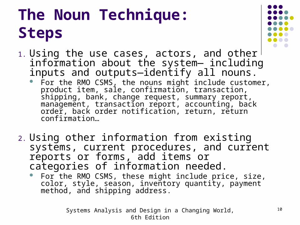
The Noun Technique:Steps1. Using the use cases, actors, and other information
about the system— including inputs and outputs—identify all nouns. For the RMO CSMS, the nouns might include customer, product item,
sale, confirmation, transaction, shipping, bank, change request, summary report, management, transaction report, accounting, back order, back order notification, return, return confirmation…
2. Using other information from existing systems, current procedures, and current reports or forms, add items or categories of information needed. For the RMO CSMS, these might include price, size, color, style,
season, inventory quantity, payment method, and shipping address.

Systems Analysis and Design in a Changing World, 6th Edition 11
The Noun Technique:Steps (continued)
3. As this list of nouns builds, refine it. Ask these questions about each noun to help you decide whether you should include it: Is it a unique thing the system needs to know about? Is it inside the scope of the system I am working on? Does the system need to remember more than one of these items?
Ask these questions to decide to exclude it: Is it really a synonym for some other thing I have identified? Is it really just an output of the system produced from other
information I have identified? Is it really just an input that results in recording some other information
I have identified?
Ask these questions to research it: Is it likely to be a specific piece of information (attribute) about some
other thing I have identified? Is it something I might need if assumptions change?

Systems Analysis and Design in a Changing World, 6th Edition 12
The Noun Technique:Steps (continued)
4. Create a master list of all nouns identified and then note whether each one should be included, excluded, or researched further.
5. Review the list with users, stakeholders, and team members and then define the list of things in the problem domain.

Systems Analysis and Design in a Changing World, 6th Edition 13
Details about Domain Classes Attribute— describes one piece of information
about each instance of the class Customer has first name, last name, phone number
Identifier or key One attribute uniquely identifies an instance of the
class. Required for data entities, optional for domain classes. Customer ID identifies a customer
Compound attribute Two or more attributes combined into one structure
to simplify the model. (E.g., address rather than including number, street, city, state, zip separately). Sometimes an identifier or key is a compound attribute.

Systems Analysis and Design in a Changing World, 6th Edition 14
Attributes and Values Class is a type of thing. Object is a specific instance of the class.
Each instance has its own values for an attribute

Systems Analysis and Design in a Changing World, 6th Edition 15
Associations Among Things Association— a naturally occurring relationship
between classes (UML term)

Systems Analysis and Design in a Changing World, 6th Edition 16
Just to Clarify…
Called association on class diagram in UML Multiplicity is term for the number of associations between
classes: 1 to 1 or 1 to many
Called relationship on ERD in database class Cardinality is term for number of relationships in entity
relationship diagrams: 1 to 1 or 1 to many Associations and Relationships apply in two directions
Read them separately each way A customer places an order An order is placed by a customer

Systems Analysis and Design in a Changing World, 6th Edition 17
Minimum and Maximum Multiplicity
Associations have minimum and maximum constraints minimum is zero, the association is optional If minimum is at least one, the association is mandatory

Systems Analysis and Design in a Changing World, 6th Edition 18
Types of Associations
Binary Association Associations between exactly two different classes
Course Section includes Students Members join Club
Unary Association (recursive) Associations between two instances of the same class
Person married to person Part is made using parts
Ternary Association (three) N-ary Association (between n)

Systems Analysis and Design in a Changing World, 6th Edition 19
The Domain Model Class Diagram Class
A category of classification used to describe a collection of objects
Domain Class Classes that describe objects in the problem domain
Class Diagram A UML diagram that shows classes with attributes and
associations (plus methods if it models software classes) Domain Model Class Diagram
A class diagram that only includes classes from the problem domain, not software classes so no methods

Systems Analysis and Design in a Changing World, 6th Edition 20
Domain Class Notation Domain class has no methods Class name is always capitalized Attribute names are not capitalized and use camelback
notation (words run together and second word is capitalized)

Systems Analysis and Design in a Changing World, 6th Edition 21
A Simple Domain Model Class Diagram
Note: This diagram matches the semantic net shown previously A customer places zero or more orders An order is placed by exactly one customer An order consists of one or more order items An order item is part of exactly one order

Systems Analysis and Design in a Changing World, 6th Edition 22
UML Notation for Multiplicity
Systems Analysis and Design in a Changing World, 6th Edition 23
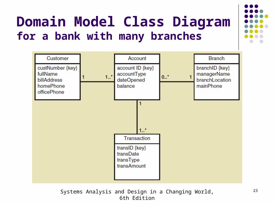
Domain Model Class Diagramfor a bank with many branches

Systems Analysis and Design in a Changing World, 6th Edition 24
Domain Model Class Diagramfor course enrollment at a university
Where is each student’s grade remembered in this model? Each section has many grades and each grade is association with a student Each student has many grades and each grade is association with a section

Systems Analysis and Design in a Changing World, 6th Edition 25
Refined Course Enrollment Modelwith an Association Class CourseEnrollment
Association class— an association that is treated as a class in a many to many association because it has attributes that need to be remembered, such as grade

Systems Analysis and Design in a Changing World, 6th Edition 26
More Complex Issues about Classes:Generalization/Specialization Relationships
Generalization/Specialization A hierarchical relationship where subordinate classes are
special types of the superior classes. Often called an Inheritance Hierarchy
Superclass the superior or more general class in a
generalization/specialization hierarchy Subclass
the subordinate or more specialized class in a generalization/specialization hierarchy
Inheritance the concept that subclasses classes inherit characteristics of
the more general superclass

Systems Analysis and Design in a Changing World, 6th Edition 27
Generalization/SpecializationInheritance

Systems Analysis and Design in a Changing World, 6th Edition 28
Generalization/SpecializationInheritance for RMO Three Types of Sales
Abstract class— a class that allow subclasses to inherit characteristics but never gets instantiated. In Italics (Sale above)
Concrete class— a class that can have instances

Systems Analysis and Design in a Changing World, 6th Edition 29
Generalization/SpecializationInheritance for the Bank with Special Types of Accounts
A SavingsAccount has 4 attributes
A CheckingAccount Has 5 attributes
Note: the subclasses inherit the associations, too
Systems Analysis and Design in a Changing World, 6th Edition 30
More Complex Issues about Classes:Whole Part Relationships Whole-part relationship— a relationship between
classes where one class is part of or a component portion of another class
Aggregation— a whole part relationship where the component part exists separately and can be removed and replaced (UML diamond symbol, next slide) Computer has disk storage devices Car has wheels
Composition— a whole part relationship where the parts can no longer be removed (filled in diamond symbol) Hand has fingers Chip has circuits

Systems Analysis and Design in a Changing World, 6th Edition 31
Whole Part RelationshipsComputer and its Parts
Note: this is composition, with diamond symbol.
Whole part can have multiplicity symbols, too (not shown)

Systems Analysis and Design in a Changing World, 6th Edition 32
More on UML Relationships
There are actually four types of relationships in class diagrams Association Relationships (“uses a”)
These are associations discussed previously, just like ERD relationships
Whole Part Relationships (“has a”) One class is a component or part of another class
Generalizations/Specialization Relationships (“is a”) Inheritance
Interface/Contract Relationships (“can do”) Interface
So, try not to confuse relationship with association

Systems Analysis and Design in a Changing World, 6th Edition 33
Summary “Things” in the problem domain are identified and
modeled, called domain classes or data entities Two techniques for identifying domain classes/data
entities are the brainstorming technique and the noun technique
Domain classes have attributes and associations Associations are naturally occurring relationships
among classes, and associations have minimum and maximum multiplicity

Systems Analysis and Design in a Changing World, 6th Edition 34
Summary
The UML class diagram notation is used to create a domain model class diagram for a system. The domain model classes do not have methods because they are not yet software classes.
There are actually four UML class diagram relationships: association relationships, generalization/specialization (inheritance) relationships, interface and whole part relationships
Other class diagram concepts are abstract versus concrete classes, compound attributes, composition and aggregation, association classes, super classes and subclasses
Systems Analysis and Design in a Changing World, 6th Edition 35
Overview
The two primary aspects of functional requirements: use cases and domain classes
Now focus on additional techniques and models to extend the requirements models to show more detail
Fully developed use case descriptions provide information about each use case, including actors, stakeholders, preconditions, post conditions, the flow of activities and exceptions conditions
Activity diagrams can also be used to show the flow of activities for a use case

Systems Analysis and Design in a Changing World, 6th Edition 36
Overview (continued)
System sequence diagrams (SSDs) show the inputs and outputs for each use case as messages
State diagrams show the states an object can be in over time between use cases
Use cases are modelled in more detail using fully developed use case descriptions, activity diagrams, and system sequence diagrams
Domain classes are modelled in more detail using state diagrams
Not all use cases and domain classes are modelled at this level of detail. Only model when there is complexity and a need to communicate details

System Sequence Diagram (SSD)
• A UML sequence diagram• Special case for a sequence diagram
– Only shows actor and one object– The one object represents the complete system– Shows input & output messaging requirements
for a use case• Actor, :System, object lifeline• Messages
Systems Analysis and Design in a Changing World, 6th Edition 37

Systems Analysis and Design in a Changing World, 6th Edition
38
Automation Boundary

System Sequence Diagram (SSD)Notation
Systems Analysis and Design in a Changing World, 6th Edition 39

Message Notation
Systems Analysis and Design in a Changing World, 6th Edition 40

SSD Message Examples with
Loop Frame
Systems Analysis and Design in a Changing World, 6th Edition 41

SSD Message Examples
Opt Frame (optional)
Alt Frame(if-else)
Systems Analysis and Design in a Changing World, 6th Edition 42

Steps for Developing SSD1. Identify input message
– See use case flow of activities or activity diagram2. Describe the message from the external actor to the
system using the message notation– Name it verb-noun: what the system is asked to do – Consider parameters the system will need
3. Identify any special conditions on input messages– Iteration/loop frame– Opt or Alt frame
4. Identify and add output return values– On message itself: aValue:= getValue(valueID)– As explicit return on separate dashed line
Systems Analysis and Design in a Changing World, 6th Edition 43

SSD for Create customer account Use case
Systems Analysis and Design in a Changing World, 6th Edition 44

SSD for Ship items Use
Case
Systems Analysis and Design in a Changing World, 6th Edition 45

State Machine Diagram• State machine diagram
– A UML diagram showing the life of an object in states and transitions
• State– A condition during an object’s life when it satisfies some
criterion, performs some action, or waits for an event
• Transition– The movement of an object from one state to another state
• Action Expression– A description of activities performed as part of a transition
Systems Analysis and Design in a Changing World, 6th Edition 46

State Machine Diagram (continued)
• Pseudo state– The starting point of a state machine diagram (black dot)
• Origin state– The original state of an object before transition
• Destination state– The state to which the object moves after the transition
• Guard condition– A true false test to see whether a transition can fire
Systems Analysis and Design in a Changing World, 6th Edition 47

State Machine Diagramfor a Printer
Systems Analysis and Design in a Changing World, 6th Edition 48

Composite States• State containing other states and transitions• Printer can be On and either Idle or Working
Systems Analysis and Design in a Changing World, 6th Edition 49

Concurrent Paths • Multiple paths in composite state• Printer On paths are independent
Systems Analysis and Design in a Changing World, 6th Edition 50

Steps for Developing State Diagram
1. Review the class diagram and select classes that might require state machine diagrams
2. For each class, make a list of status conditions (states) you can identify
3. Begin building diagram fragments by identifying transitions that cause an object to leave the identified state
4. Sequence these states in the correct order and aggregate combinations into larger fragments
5. Review paths and look for independent, concurrent paths
Systems Analysis and Design in a Changing World, 6th Edition 51

Steps for Developing State Diagram (continued)
6. Look for additional transitions and test both directions7. Expand each transition with appropriate message
event, guard condition, and action expression8. Review and test the state machine diagram for the
class– Make sure state are really state for the object in the class– Follow the life cycle of an object coming into existence and
being deleted– Be sure the diagram covers all exception condition– Look again for concurrent paths and composite states
Systems Analysis and Design in a Changing World, 6th Edition 52

Extending and Integrating Requirements Models
• Use cases– Use case diagram
• Use case description• Activity diagram• System sequence diagram (SSD)
• Domain Classes – Domain model class diagram
• State machine diagram
Systems Analysis and Design in a Changing World, 6th Edition 53

Integrating Requirements Models
Systems Analysis and Design in a Changing World, 6th Edition 54
Summary
Systems Analysis and Design in a Changing World, 6th Edition
55
Modelled the two primary aspects of functional requirements: use cases and domain classes
Focus on additional techniques and models to extend the requirements models to show more detail
Fully developed use case descriptions provide information about each use case, including actors, stakeholders, preconditions, post conditions, the flow of activities and exceptions conditions
Activity diagrams can also be used to show the flow of activities for a use case

Summary (continued)
Systems Analysis and Design in a Changing World, 6th Edition
56
System sequence diagrams (SSDs) show the inputs and outputs for each use case as messages
State diagrams show the states an object can be in over time between use cases
Use cases are modelled in more detail using fully developed use case descriptions, activity diagrams, and system sequence diagrams
Domain classes are modelled in more detail using state diagrams
Not all use cases and domain classes are modelled at this level of detail. Only model when there is complexity and a need to communicate details

57
Deliverable 2 (Project Requirements) Let’s review Deliverable 2 together which is due: NEXT WEEK! For detailed instructions and a link to the rubric please visit:
http://sacapstone.wikidot.com/deliverable2instructions

58
Group Meetings Please break into your Capstone Groups to plan and
work on Deliverable 2! We will be meeting with each group today to assess
your progress and provide some advice
Related Documents