Journal of Materials Processing Technology 224 (2015) 156–168 Con tents lists available at ScienceDirect Journalof MaterialsProcessingTechnology j ourna l h om e p a g e : www.elsevier.com/locate/jmatprotec Diedesignmethodforthinplatesbyindirect rheo-casting processand effectof diecavityfrictionandpunchspeedonmicrostructures and mechanical properties ChulKyu Jin a , Chan gHyun Jang a ,ChungGilKang b,∗ a Pre cision Manufa cturing Sys tem Divisi on, Graduate School , Pusan Nat iona l Univers ity , San 30 Chang Jun-do ng, Geum Jung-Gu, Busan 609-7 35, South Korea b Engine erin g Res ear ch Centerfor Net Sha pe and Die Manufactu ring, School of Mec hanical Enginee ring, Pus an Nat ional Uni ver sit y, San 30 Chang Jun-do ng, Geum Jung-Gu, Busan 609-735, South Korea articl einfo Article history: Rec eiv ed 12 Nov emb er 2014 Rec eiv ed in rev ise d for m 28 Apr il 2015 Acc ept ed 1 May 2015 Avail abl e onl ine 12 May 2015 Keywords: Semi-solid slurry Indirect rheo-casting Electromagnetic stirring Thin plate Filli ng simu latio n A356 alloy abstract Thinplateswithathicknessof 1.2mmare fabri cated fromsemi-solidA35 6 all oythroughanindirect rheo-castingprocessbothwithandwithoutanelectromagnetic stirrer(EMS).Thethindiecavityfor formingis desig nedwiththefluidanalysissoftwareMAGMA. A semi- solid slurrywitha soli dfractionof 40%is prepa redandtheninjectedintothedieof a200thydraulicpress.Formingtestsareperformedon thethin plate sat twopunchspeeds(30and 300mm/s)andtwocavityfrictionconditions(m f =0.4and m f =0.9).Theformability, mechanical properties, andmicrostructurearethenevaluated. Thesemi-solid slurryobtainedwithanEMScontainsfineandglobularsolidparticles;thesemi-solidslurryproduced withoutanEMSrevealsrosetteparticlesandcoarserglobularsolidparticles.At hi ghfriction(m f = 0.9 ), thecavityis mainlyfilledwiththeliquidphase.Ata hi gherpunchrate,thethi n pla tes showbetter formabilityanda microstructure withfineandevensolidparticles.Thetensilestrengthandelongation of thethinplateformedwithapunchspeedof 300mm/sinthecavitywithgraphitelubrication(m f =0.9) are216MPaand10%,respectively. Thesevaluesare57MPaand5.5%higher, respectively, thanthoseof thethi n pla teformedata pun chspeedof 30mm/s. ©2015ElsevierB.V.Allrightsreserved. 1. Intr oduc ti on The die castin g pro cess for aluminium involves the high-s peed inject ion of molt en metal, which leads to internal defects because of remaining ga s or ai r in the molt en me tal, which in tu rn dete ri- orates the mec hanica l pro per ties. Ni u et al . (200 0) f ound that the volume of gas porosi ty and the pore sizes in the cast ings are signif - ican tl y reduced through the use of a vacuum duri ng di e ca st ing. This markedly improves the densit y and mechanical proper ti es, pa rt ic ular ly the tensile strength an d ductilit y. The forgin g pr o- cess ha s li mi ted formab il it y of near-net shap es and redu ces th e after -trea tmentproduct ivityand die life,which makeseco-friend ly pro duc tio n imp ossibl e. Squ eeze casting is a metal for min g pro cess where molten met al is sol idi fied und era rel ati vel y high pressure to red uce gas or shr ink age por osi ty. However, this pro ces s pro duc es a ros ett e and den dri testruct ure (Yue and Cha dwi ck,1996) and has ∗ Cor res pon ding aut hor . Tel .: +82 51 5101455; fax: +8251 518 1456. E-ma il address: [email protected] (C.G. Kang). the dis adv antages of a sho rte ned dielife, limite d sha pe comple xit y, dif ficu ltywith pro duc ingthin par ts,and limite d maximum siz e and weight (Ghomashc hi and Vik hro v, 2000). Fl emin gs et al . (1 976) developed a rheologi cal (semi- soli d) ma terial and th e rheocasting pr oc ess as an alte rnative to metal forming pr oc esses such as di e cast ing and forgin g. Thei r pr ocess pro duc es a highly flui d slu rry of sol id sphero ids dis per sed in liq uid . Joly and Mehrabian (1976) showed that the vi scosit y of the slur ry at a gi ven volume fr ac ti on of soli ds decr eases wi th a decr ea si ng cool ing rate and increasi ng shear rate. The rheo-f ormi ng method, whic h is perf orme d on a ma teri al in th e semi -s ol id state (i .e., th e te mp era t ur e is abov e th e so li d li ne but be low the li qu id one ), is a solution to the pro bl ems of ca st in g a nd fo r mi n g pr oc e ss es . In the rheo-f orming process, mol ten alu min ium is sti rre d as the tem- pera tu re is de creased in orde r to cr ea te semi-solid sl ur ry wi th a cont roll ed grai n size, which is then injected into a di e and formed wi th a press. Kapranos et al . (200 0) described the pr ocess of pro- duc ing andassess ing a high-qual ity thi xof ormed compon ent usi ng an al umi ni um all oy an d sh owed tha t th ix ofo rmi ng cl ea rl y ha s near net-s hape capa bilit y. Ji et al. (2001) develop ed a twin-screw http://dx.doi.org/10.1016/j.jmatprotec.2015.05.002 0924-0 136/© 2015 Else vier B.V. All righ ts rese rved .

Welcome message from author
This document is posted to help you gain knowledge. Please leave a comment to let me know what you think about it! Share it to your friends and learn new things together.
Transcript
7/18/2019 1-s2.0-S0924013615002022-main
http://slidepdf.com/reader/full/1-s20-s0924013615002022-main 1/13
Journal of Materials Processing Technology224 (2015) 156–168
Contents lists available at ScienceDirect
Journal of Materials Processing Technology
journal homepage: www.elsevier .com/ locate / jmatprotec
Die design method for thin plates by indirect rheo-casting process and
effect of die cavity friction and punch speed on microstructures and
mechanical properties
Chul Kyu Jina, Chang Hyun Janga, Chung Gil Kangb,∗
a PrecisionManufacturing SystemDivision, Graduate School, Pusan National University, San30 Chang Jun-dong, Geum Jung-Gu,
Busan609-735, SouthKoreab Engineering Research Center forNet Shape andDieManufacturing, School of Mechanical Engineering, Pusan National University, San30 Chang Jun-dong,
Geum Jung-Gu, Busan 609-735, South Korea
a r t i c l e i n f o
Article history:
Received 12 November 2014
Received in revised form 28 April 2015
Accepted 1 May2015
Available online12May2015
Keywords:
Semi-solid slurry
Indirect rheo-casting
Electromagnetic stirring
Thinplate
Filling simulation
A356 alloy
a b s t r a c t
Thin plates with a thickness of 1.2mm are fabricated from semi-solid A356 alloy through an indirect
rheo-casting process both with and without an electromagnetic stirrer (EMS). The thin die cavity for
forming is designedwith the fluid analysis software MAGMA. A semi-solid slurry with a solid fraction of
40% is prepared and then injected into the die of a 200 t hydraulic press. Forming tests are performed on
the thin plates at two punch speeds (30 and 300mm/s) and two cavity friction conditions (m f = 0.4 and
m f =0.9). The formability, mechanical properties, andmicrostructure are then evaluated. The semi-solid
slurry obtained with an EMS contains fine and globular solid particles; the semi-solid slurry produced
without an EMS reveals rosette particles and coarser globular solid particles. At high friction (m f = 0.9),
the cavity is mainly filled with the liquid phase. At a higher punch rate, the thin plates show better
formability and a microstructure with fine and even solid particles. The tensile strength and elongation
of the thin plate formedwith a punch speed of 300mm/s in the cavitywith graphite lubrication (m f =0.9)
are 216MPa and 10%, respectively. These values are 57MPa and 5.5% higher, respectively, than those of
the thin plate formed at a punch speed of 30mm/s.
© 2015 Elsevier B.V. All rights reserved.
1. Introduction
The die casting process for aluminium involves the high-speed
injection ofmoltenmetal, which leads to internal defects because
of remaining gas or air in the molten metal, which in turn deteri-
orates the mechanical properties. Niu et al. (2000) f ound that the
volumeof gas porosityand the pore sizes in the castings are signif-
icantly reduced through the use of a vacuum during die casting.
This markedly improves the density and mechanical properties,
particularly the tensile strength and ductility. The forging pro-
cess has limited formability of near-net shapes and reduces the
after-treatmentproductivityand die life,whichmakeseco-friendly
production impossible. Squeeze casting is a metal forming process
wheremoltenmetal is solidifiedunder a relatively high pressure to
reduce gas or shrinkage porosity. However, this process produces
a rosette anddendrite structure (YueandChadwick, 1996) andhas
∗ Corresponding author. Tel.: +8251 5101455; fax: +8251 5181456.
E-mail address: [email protected] (C.G. Kang).
thedisadvantages ofa shorteneddielife, limited shapecomplexity,
difficultywithproducingthinparts,and limitedmaximumsize and
weight (Ghomashchi andVikhrov, 2000).
Flemings et al. (1976) developed a rheological (semi-solid)
material and the rheocasting process as an alternative to metal
forming processes such as die casting and forging. Their process
produces a highlyfluid slurryof solid spheroidsdispersed in liquid.
Joly and Mehrabian (1976) showed that the viscosity of the slurry
at a given volume fraction of solids decreases with a decreasing
cooling rate and increasing shear rate. The rheo-forming method,
which is performed on a material in the semi-solid state (i.e., the
temperature is above the solid line but below the liquid one), is
a solution to the problems of casting and forming processes. In
the rheo-formingprocess, moltenaluminium is stirred as the tem-
perature is decreased in order to create semi-solid slurry with a
controlled grain size, which is then injected into a die and formed
with a press. Kapranos et al. (2000) described the process of pro-
ducingandassessinga high-quality thixoformed componentusing
an aluminium alloy and showed that thixoforming clearly has
near net-shape capability. Ji et al. (2001) developed a twin-screw
http://dx.doi.org/10.1016/j.jmatprotec.2015.05.002
0924-0136/©2015 Elsevier B.V.All rights reserved.

7/18/2019 1-s2.0-S0924013615002022-main
http://slidepdf.com/reader/full/1-s20-s0924013615002022-main 2/13
C.K. Jin et al./ Journal of Materials Processing Technology 224(2015) 156–168 157
rheo-moulding process, and Fan et al. (2005) presented a rheo-
diecasting (RDC) process which directly uses liquid Al alloys.
Their results indicated that the RDC samples had close to zero
porosity and a fine and uniform microstructure throughout the
entire sampleunder theas-cast condition. Atkinson (2005) summ-
arised routes to spheroidal microstructures, types of semi-solid
processing, the advantages and disadvantages of these routes, the
background rheology, mathematical theories of thixotropy, the
transientbehaviourof semi-solidalloy slurries, and computational
modelling.
The one major drawback of rheo-forming or thixoforming for
processing semi-solid metals is controlling the liquid or solid seg-
regation (i.e., separation of the solid and liquid phases or uneven
distribution of the solid phase). When a semi-solid slurry fills the
die, the material comes in contact with the cavity’s wall. This
causes uneven flows leading to segregation of the solid phase
(primary -Al particles) from the liquid phase. Chen and Tsao
(1997) proposed semi-solid deformation mechanisms and pre-
dicted the segregation phenomenon based on deformation of a
phenomenologicalmodel. Kang et al. (2007) investigatedtheeffect
of changing the injection velocity on the globular microstructure
and mechanical properties of a product from semi-solid die cast-
ing. They found that the difference in the solid fraction between
samples with and without liquid segregation was approximately
15–20%. For thin plates, segregation of the solid and liquid phases
can be more severe, which makes their mechanical properties
uneven at different locations. Because of the problems associated
with segregation and the low initial forming temperatures for
semi-solid metal processing, no research has been carried out so
far on the fabrication of thin plates with the rheo-forming pro-
cess.
In this study, an indirect rheo-casting process was applied to
compensate for the disadvantages of indirect squeeze casting and
produce aluminium thin plates for electric and automobile parts
and fuel cell bipolar plates. The indirect rheo-casting process for
thin plates involves a low pouring temperature in a thin die cav-
ity. This makes it highly likely that the material will fail to fill the
cavity entirely and solidify starting from the centre, which willresult in incomplete forming. Therefore, the aim of this study was
to find ways to design a die for indirect rheo-casting which are
appropriate for the thin plate’s shape. A gate shape and overflow
adequate for rheological behaviour were designed with the soft-
ware MAGMA to allow the semi-solid slurry to fill the cavity. The
A356 alloy with a wide solid-liquid coexistent region was used as
the semi-solid slurry. A semi-solid slurry with fine and globular
solid particles was fabricated through the use of an electromag-
netic stirrer (EMS) to control the grain size of the A356 alloy.
The semi-solid slurry was injected into a die installed in a 200-
t hydraulic press to form a thin plate. Experiments for forming
thin plates were performed at two punch speeds and two cavity
friction conditions, and the effect of the punch speed and fric-
tionon the formability,microstructure, andmechanical propertieswas analysed. The microstructure and mechanical properties of
the formed thin plate samples were measured at different loca-
tions.
2. Experimental procedure
2.1. Semi-solid flowmodel
The fluid model of semi-solid materials shows that the viscos-
ity depends on the shear rate. Semi-solid materials lose viscosity
drastically as theshear rate increasesbuthave nearly constant vis-
cosityat very lowshearrates. Inorder toexpress thedependenceof
viscosity on the shear rate in a high shear rate region, an empirical
formula called a power law is used (KimandKang, 2000; Atkinson,
2005):
= k n−1 (1)
where istheshear stress, is theshearrate, k is thepower lawfac-
tor, andn is the power law index.Whenn=1, thematerialbecomes
a Newtonianfluid whose viscosity isthesame ask. Kim and Kang
(2000) set n=1 for the Newtonian fluidmodel. For the Ostwald–de
Waelefluidmodel,whichis forthesemi-solid state,theexperimen-tally obtained n value was −0.48 to 0.45 (shear rate= 3–2500s−1).
Thiswasapplied inMAGMASOFTforcomparisonof thefillinganal-
ysis results within the die. Their results demonstrated that the
Ostwald–deWaele fluid model is consistent with the experimen-
tal results. The viscous behaviour model of MAGMASOFT uses the
Ostwald–de Waele model, which expresses the non-Newtonian
aspect of semi-solid materials through a power law:
n = m n−1 (2)
where is the apparent dynamic viscosity, m is the Ostwald–de
Waele coefficient, n is the Ostwald–de Waele exponent, and is
the density.
Thegoverningequationsof MAGMASOFTare thecontrolvolume
finitedifferencemethod, continuityequation,Navier–Stokes equa-tion, energyequation,andvolumeoffluid (VOF)method. These are
the same used for liquids.
2.2. Simulation preparation for die design
When a semi-solid slurryis compressed, theliquid phasemoves
towards the surface of the slurry, which leads to surface cracks.
The void content and segregation of the solid and liquid phases
becomemore severe at the side of the compressed specimen. Seo
et al. (2002) conducted compression experiments to investigate
the deformation behaviour of a semi-solid material with vary-
ing processing parameters, such as the test specimen size and
strain-rate.They suggestedthat therheo-forgingdie for thin plates
must be designed as an indirect type of structure. To form thin
platesusing a semi-solid slurry, a die for indirect rheo-castingwas
designedwherefilling is carried outbycompressing thesemi-solid
slurry in closed upper and bottomdies with a punch. Because this
structure is similar to thediecasting process, thedesignof thegate
systemand overflow is a critical variable.Analysis of thebehaviour
of the semi-solid slurryas it goes through the gateand fills the cav-
ity is a major factor for the design of thin plates. Seo et al. (2007)
analysed how the gate shape affects the liquid segregation of a
semi-solid slurry and concluded that a wider gate makes filling
more likely to be done in order and liquid segregation less likely
to form.
In order to examine the filling behaviour of a semi-
solid slurry according to the gate shape, a thin plate cavity
(150mm×150mm×1.2mm) was simulated with different gate
shapes. The simulations were performed by using the A356 thixo-module (Ostwald–de Waele model) of MAGMA. Table 1 lists the
Table 1
Simulation parameters.
Parameters Values
Molten metal Material A356
Liquidus temperature (T L) 617 ◦C
Solidus temperature (T S ) 547 ◦C
Initial temperature (T M ) 596 ◦C
Latentheat (Q ) 430kJ/kg
Die Material SKD 61
Initial temperature (T D) 300 ◦C
Heat transfer coefficient Material and die 7000W/m2 K
Die and die 1000W/m2 K

7/18/2019 1-s2.0-S0924013615002022-main
http://slidepdf.com/reader/full/1-s20-s0924013615002022-main 3/13
158 C.K. Jin et al. / Journal of Materials Processing Technology 224 (2015) 156–168
Table 2
Chemical composition of A356 alloy (wt%).
Si Mg Ti Fe Ni Mn Zn Pb Al
7.08 0.35 0.17 0.08 0.07 0.01 0.01 0.01 Bal.
conditions and heat transfer coefficient values used in the simula-
tion.
2.3. Fabrication of semi-solid slurry
A356 alloy was used for the semi-solid slurry, and an EMS was
used to control the size of the solid particles. Because A356 alloy
hasgreatfluidityat thetwo-phasemushyzoneandcanenhance the
mechanical strength with heat treatment, it is used in automobile
parts such as knuckles, arms, and housing that require reliability.
In particular, themechanical properties of A356 are closely related
tothesize of theprimaryparticles, secondarydendritearm spacing
(SDAS), and Si particle shape and distribution within the eutectic
matrix. Table 2 lists thechemical compositionsof A356 alloy.Fig. 1
shows the solid fraction versus temperature of theA356 alloy. The
solid phase fraction of A356 alloy at different temperatures was
determined by using the obtained differential scanning calorime-
try (DSC) curve. The liquidus and solidus temperatures for A356
alloy were 617 and 547 ◦C, respectively, and the solid fraction for a
temperature of 596◦C was 40%.
Fig. 2(a) shows a photo of the EMSused in this study. The EMS
consisted of three phases (P, R, S) and three poles witha coil placed
Fig. 1. Solid fraction versus temperature of A356 alloy.
Fig. 2. Electromagnetic stirrer: (a) real picture and (b) schematic diagram.
Fig. 3. Variations in magnetic induction density at three positions as function of
stirring current.
vertical to the core. The core for fixing the coil positionwas fabri-
cated by piling up several 0.35mm thick plates. The core consisted
of240unit laminationsof Si–Znalloyplates,andthecoilwaswound
around the core. Each phase was placed in a cylindrical direction,
as shown inFig. 2(b), tolet the currentmovealongside the coil, and
an electromagnetic force was generated in the cylindrical direc-
tion to stir the moltenmetal. The electromagnetic force of the EMS
was measured with a gaussmeter at three positions. Fig. 3 shows
thevariations in themagnetic inductiondensity measured at three
positions insidetheEMSasa functionof thecurrent. Themeasured
magnetic inductiondensity wasproportional to the increase in the
current at each position. At a current of 60A, the magnetic induc-
tion densities at the upper, middle, and lower positions were 640,
680and 1120G, respectively.Thestirringforceinducedshearstress
in themolten aluminium, which controlled thegrowthof dendrite
arms which form during solidification. Thus, it controlled thegrain
size of the solid phase and made the grains globular.
Fig. 4 shows the process to make a semi-solid slurry. First, the
cup is inserted intothe EMS, and a ladle isused toscoop themoltenmetal from the furnace. Then, stirring starts as the electric current
is applied while themoltenmetal is poured into the EMS cup. (The
molten metal is at a temperature of 680 ◦C in the furnace, 635 ◦C
in the ladle, and 620 ◦C in the cup.) Stirring is performed until the
temperature of the moltenmetal in the cup cools to596 ◦C, i.e., the
solid fraction ( fs) is 40%. It takes about 78s of stirring to reach this
level. The variables for the stirring experiment were the molten
metal temperature at the start of stirring (T S ), the stirring current
( A), and the stirring time (t ). Bae et al. (2007) suggested that fine
and globular solid particles can formwhen the moltenmetal tem-
perature at the start of stirring is below 655 ◦C, the stirring current
is 60A, and the stirring time is 60s based on an electromagnetic
stirring experiment using A356. Therefore, in the present experi-
ment, the molten metal temperature was 620◦
C, and the stirringcurrent was 60A, as given in Table 3.
Stainless steel 304 was used for the EMS cup. Stainless steel is
nonmagnetic because it is austenitic, so it is not affected by elec-
tromagnetic forces. In addition, stainless steel 304doesnotdeform
even at temperatures over 700 ◦C. Seo et al. (2002) performed a
compression experiment ona semi-solid slurryand examinedhow
changes intheheight anddiameter of thebilletaffecttheliquidseg-
regation. They concluded that a larger billetdiametermakes it less
likelyforporesand liquidsegregationtooccur. Inaddition, a greater
billet lengthincreasesthevoid content gets. Thus, after theamount
ofmaterial required forthinplate formingwasconsidered,the EMS
cup was designed to have a similar diameter to the inner diameter
of the die sleeve (60mm) and a much lower height. Fig. 5(a) and
(b) illustrates the shape dimensions of the EMS cup and actual cup,

7/18/2019 1-s2.0-S0924013615002022-main
http://slidepdf.com/reader/full/1-s20-s0924013615002022-main 4/13
C.K. Jin et al./ Journal of Materials Processing Technology 224(2015) 156–168 159
Fig. 4. EMS process for fabricating semi-solid slurrywith fine andglobular solid particles.
Table 3
Experimental conditions for semi-solid slurry fabrication.
Parameters Values
Stirring method Electromagnetic stirring
Stirring current (A) 60A
Temperature at thestart of
stirring (T S )
620 ◦C
Temperature at thefinish
of stirring (T F )/solid
fraction ( fs)
596 ◦C/40%
Stirring time (t ) 60 s
Fig. 5. Geometries of stirring cup and slurry: (a) section of cup, (b) photo of cup,and (c)photoof semi-solid slurry.
respectively. Fig. 5(c) shows the semi-solid slurry. The cup is 2mm
thick and 100mm long. Because the molten metal rotates during
stirring because of the stirring force, the molten metal will flow
over the cup if the cup is filled to the inlet. Therefore, the cup was
filled to a height of 90mm with the moltenmetal. The volume of
the fabricated semi-solid slurrywas165,597mm3, and the volume
of thethinplatemodel calculated using thespacefinder functionof
the software UGNX6 was 161,304mm3. The amount of semi-solid
slurrywas adequate to fill the thin cavity.
2.4. Indirect rheo-casting process
Thesemi-solidslurry( fs=40%)producedbytheEMSexperiment
was injected into the die in a 200t hydraulic press for the thin
plate forming experiment. Fig. 6 shows the 200t hydraulic press
with the installed die for thin plates. Table 4 and Fig. 7 present the
experimental conditions for the thin plate forming process and a
general diagramof theprocess, respectively. Thedie’s temperature
was maintained at 280–290 ◦C with a cartridge heater. The pres-
sure of the punch was set to 200MPa, and two speed were used:
30 and 300mm/s. The semi-solid slurry was injected into the die
and compressed with the punch; the pressurewas maintained for
5s. To ensure that the formedplate would not be deformed by the
ejector pin, the die was left open for 10s for some solidification.
Then, the plate was taken out of the die and immediately cooled in
water.
Fig. 6. 200-t hydraulic presswith die installed forthin plate fabrication.
Table 4
Experimental conditions for indirect rheo-castingwith semi-solid slurry.
Parameters Value
Temperature and solid fraction
of semi-solid slurry
596 ◦C and 40%
Temperature of die 280–290 ◦C
Pressure of press punch (P P ) 200MPa
Velocity of press punch (V P ) 30 and 300mm/s
Lubricant for die cavity Graphite
Condition1 V P = 300mm/s, without lubricant(m f = 0.9)
Condition2 V P = 300mm/s, graphite lubricant (m f = 0.4)
Condition3 V P = 30mm/s, graphite lubricant (m f = 0.4)
Pinsky et al. (1984) discovered that segregation of the solid
and liquid phases increases with friction between the die and
material in compression and ring compression experiments on
semi-solid Sn–Pb alloy. Kang et al. (1999) performed compres-sion experiments on semi-solid materials at different strain rates
and concluded that the solid phase is evenly distributed at high
strain rates,which leads to less liquidsegregation. Therefore, three
forming experiments were performed to analyse the formability,
microstructure, and mechanical properties for two friction con-
ditions between the cavity and semi-solid slurry and two punch
speeds. A graphite lubricantwas sprayed in thecavityfor theform-
ing experiment with two punch speeds, and the experiment was
performedwith a non-lubricated cavity to analyse the segregation
of the solid and liquid phases aswell as defects for different cavity
friction states. Experiment condition1wasa non-lubricated cavity
(m f =0.9)witha punch speed of300mm/s.Conditions2 and 3were
a graphite-lubricatedcavity(m f =0.4)withpunchspeedsof 300and
30mm/s, respectively. These conditions are listed in Table 4. Five

7/18/2019 1-s2.0-S0924013615002022-main
http://slidepdf.com/reader/full/1-s20-s0924013615002022-main 5/13
160 C.K. Jin et al. / Journal of Materials Processing Technology 224 (2015) 156–168
Fig. 7. Schematicdiagram of indirect rheo-castingprocess: (a) input semi-solid slurry, (b) forming, and(c) ejecting.
testswere performedundereach experiment conditiontoproduce
a total of 15 thin plate samples.
2.5. Measurement of microstructure and mechanical properties
The size andglobularity of the solid particles in themicrostruc-
ture were measured using an image analyser. The equivalent
diameter (average size) of the solid particles is defined by Eq. (3)
below,andtheshape factor (globularity) represents theroundnessof the particles and is defined by Eq. (4). When R=1, a particle has
a perfectly circular shape; for a less globular particle, R>1 because
it hasa longer circumference than a circular particlewith thesame
area.
D =
4 A
(3)
R =P 2
4A (4)
here D, R, A, and p are the diameter, radius, area, and perimeter,
respectively, of a globule.
Fig. 8. Mould-fillingbehaviour of semi-solid slurryaccording to gate shape: (a) straight gate and (b)fan gate.

7/18/2019 1-s2.0-S0924013615002022-main
http://slidepdf.com/reader/full/1-s20-s0924013615002022-main 6/13
C.K. Jin et al./ Journal of Materials Processing Technology 224(2015) 156–168 161
Fig. 9. (a)Detail designof fan gate system(unit: mm)and (b)material age.
In order to analyse the mechanical properties of the formed
thin plate, a tensile test was performed on specimens fabricated
withdifferentcavity locations.The tensile specimenswereflatwith
a 25mm gage length and 6mm width; there were fabricated in
accordance with the ASTM E 8M specifications (sub-size speci-men). The specimens were set to be as thick as the sample thin
plate. For the tensile test, a 25-t MTS was used, and the strain rate
wasset to1mm/min. Foraccuratemeasurement of theelongation,
an extensometer was used; this is a method to contact speci-
mens. The tensile test specimenswere used tomeasure theVickers
hardness. Each specimen was tested three times and five times
for tensile and hardness, respectively. The results were averaged,and the maximum and minimum values are presented with an
error bar.
Fig. 10. Mould-fillingbehaviour of semi-solid slurry formodelwith twooverflows at side: (a)velocity and (b)temperature.

7/18/2019 1-s2.0-S0924013615002022-main
http://slidepdf.com/reader/full/1-s20-s0924013615002022-main 7/13
162 C.K. Jin et al. / Journal of Materials Processing Technology 224 (2015) 156–168
3. Result and discussion
3.1. Simulation for die design
To design the gate shape for a thin plate, the biscuit was set
to 60mm, which was equivalent to the inner diameter of sleeve.
Fig. 8(a) shows the filling behaviour of the semi-solid slurry in a
die cavitywith a straight gate. As shown in the simulation results,
the slurry filled the cavity in a straight line along the gate’s shape
because of its viscosity. The sides of the cavity were filled by the
backflow of the fluid, which reached the end of the cavity and
returned. This may cause incompletefilling on the sides of the cav-
ity. Thus, the gatewas expanded to a fan type so that the material
could fill up the entire cavity after passing through the gate. The
length of the gate was shortened to avoid the semi-solid slurry
solidifying within the cavity duringfilling. Fig. 8(b) shows that the
entirewidth of the cavitywasfilled as thematerial passed through
the gate.
After a fanshapewasselected,specificdetailswere designed for
the gate. As shown by the gate cross-section in Fig. 9, the gatewas
18mm thick at thepartconnectedto thebiscuit andthennarrowed
closerto thecavity.Foreasyremovalofthe formedthinplate,5◦ and
6◦ gradientswere setfor thebiscuit’stop andbottomparts, respec-
tively, along the parting line of the die. Each corner was rounded.
When themoltenmetalcooledtoa semi-solid slurry, theupperpart
of the slurryhad a poor surface state because of the air inflow from
outside; the surface of the slurry was 3 ◦C lower than the centre
because of heat transfer. Because the upper part of the semi-solid
slurry was injected into the die first, the poor upper part of slurry
mayflowintothe cavityandcauseincompletefilling. Toaccount for
this possibility, the gate was located 4mmhigher than the bottom
part of thebiscuit (i.e., around the semi-solid slurryupper part), as
shown in Fig. 9(a). The poor upper part (further solidified) of the
slurry does not fill the cavity and is placed at the area of the semi-
solid slurryupperpart. Fig. 9(b) shows thematerial ageresults; the
initial material did not flow into the cavity. The material age refers
to the elapsed time for material inflow; a longer time indicates an
earlier material inflow.
Thefan gate causedthematerial tofillthe entirecavity.Theflow
rate at thesidesof thecavity increasedaswell, asshowninFig.8(b).
Because the flow at the sides of the cavity reaches the end of the
cavity faster than the flow at the centre of the cavity, the gas or air
in thecentre cannotbe released through thedie’spartinglineandis
lockedinside thecavityinstead.The formedsample surfacemay be
rough at the end of the cavity because of defects such as pores, air
pockets, and flow marks. In addition, an uneven filling speed may
cause the solid and liquidphases to segregate. Therefore, to obtain
a uniform flow rate within the cavity, two overflows at the sides
of the cavity were designed. Fig. 10 shows the simulation results
for a model with two overflows placed at the sides of the cavity.
As the faster flow on the cavity sides was led to the overflows,
the cavity was evenly filled overall. However, when the material
passed through the cavity’s centre, the velocity and temperature
dramatically dropped. After the cavity was totally filled, the tem-
perature at the end of the cavitywas below585 ◦C. These may lead
to incomplete filling at the end of the cavity in an actual forming
experiment,which cancause casting defects such as surface cracks
and pores. Because the material portion that solidifies at temper-
atures below 585 ◦C at the end of the cavity can also be removed
with an overflow, five overflows were placed at the cavity end, as
Fig. 11. Mould-fillingbehaviour (temperature) of semi-solid slurryfor modelwith twooverflowsat side andfiveoverflows at end.
Fig. 12. Pressure distributionin cavity formodels: (a) twooverflows at side andfive overflows at end, (b) four overflowsat side andfive overflows at end.

7/18/2019 1-s2.0-S0924013615002022-main
http://slidepdf.com/reader/full/1-s20-s0924013615002022-main 8/13
C.K. Jin et al./ Journal of Materials Processing Technology 224(2015) 156–168 163
Fig. 13. Indirect rheo-castingdie for forming thin plateswith semi-solid slurry: (a) photo of real die cavity and (b) die structure.
shown in Fig. 11. The material part that solidified at below 585
◦
Cfilled the five overflows at the cavity end, and the temperature in
the cavitywas maintained at 590 ◦C.
Fig. 12(a) shows the pressure distribution in the cavity. The
pressure distributionwassignificantlyuneven. Thepressure at the
sides was about atmospheric pressure (1013mbar). Applied pres-
sure was lost, and some areas were subjected to pressures over
10,000mbar.The fiveoverflowsat theendof cavitywere subjected
to atmospheric pressure. The applied pressurewasnot transferred
to the cavity endbecause of the uneven pressure distribution. Thisresult shows that incomplete filling may occur at the entrance
of overflows in an actual forming experiment. In order to solve
this problem, two overflows were added at the sides, as shown
in Fig. 12(b). A pressure of over 4000mbarwas evenly distributed
over the cavitywith the two addedoverflows.
Based on the simulation results, the cavity shape and die struc-
ture were designed as shown in Fig. 13(a) and (b), respectively.
Because thedie’stemperatureshouldstay at280–290◦Cduringthe
Fig. 14. Microstructuresof semi-solid slurry(a) with and (b)without EMS.

7/18/2019 1-s2.0-S0924013615002022-main
http://slidepdf.com/reader/full/1-s20-s0924013615002022-main 9/13
164 C.K. Jin et al. / Journal of Materials Processing Technology 224 (2015) 156–168
Fig. 15. Volume fraction, equivalent diameter, and roundness of solid particles in
semi-solid slurrywith andwithout EMS.
forming experiment, three andfourФ20mm holesweremachined
in the upper and bottom dies, respectively, as cartridge heater
holes. Then, Ф1.8mm holes were machined at the centres of the
upper and bottom die, and a K-type thermocouple was inserted
for measurement and control of the die temperature. For easy
removal of thethinplatesampleafterforming,Ф14mmholeswere
machined for ejector pins: one at the sleeve, six at the cavity, and
one for each overflow. The diameter of the punch for compress-
ing the semi-solid slurry was 60mm, which was the same as the
sleeve’s inner diameter. The upper part of the punchhad a diame-
ter of 100mmtoprevent the punch frombuckling during repeated
experiments. To prevent the aluminium alloy from sticking to the
die surface and enhance the surface hardness, the punch, sleeve,
and cavitywere heat-treated through nitriding.
Fig. 16. Thin plate samples fabricated with different punch speeds (V P ) and friction states of cavity: (a) 30mm/s,without lubricant; (b) 300mm/s, graphite lubricant; and
(c) 30mm/s, graphite lubricant.

7/18/2019 1-s2.0-S0924013615002022-main
http://slidepdf.com/reader/full/1-s20-s0924013615002022-main 10/13
C.K. Jin et al./ Journal of Materials Processing Technology 224(2015) 156–168 165
Fig. 17. Thickness of formedthin plates.
3.2. Microstructures of semi-solid slurry
Before the thin plate forming experiment, the semi-solid slurryneeded to be cooled down immediately in water for analysis of
themicrostructure. Fig. 14 shows themicrostructures of the semi-
solid slurry stirred with an EMS and not stirred but cooled down
to 596 ◦C. The microstructure showed primary -Al for the solid
phase and a eutectic phase for what used to be the liquid phase
in the solid–liquid state. In the microstructure with stirring, fine
and globular solid particles were distributed evenly at the centre
of the semi-solid slurry because the uneven growth of particles
wascontrolled (Fig. 14(a)).At the sides of the semi-solid slurry, the
cup’s surfacewasabout3 ◦C lower at the centre because of the heat
transfer during stirring. Thus, the solid particleswere coarser than
at thecentre. For themicrostructurewithout stirring, a large num-
ber of rosette particles, dendrites, and some fine globular particles
were distributed (Fig. 14(b)). The moltenmetal grew as a dendrite
structure until it cooleddown to596 ◦C. The grain sizewas coarser
around the sides of the material.
Fig. 15 shows the volume fraction, equivalent diameter, and
roundness of the solid particles in the semi-solid slurry with and
without an EMS. At thecentre, theequivalent diameter andround-
ness of thesolidparticlesof thesemi-solid slurrywithanEMSwere
75mand1.5,respectively.Thoseof thesolidparticlesof thesemi-
solid slurrywithout an EMSwere 110mand2.3, respectively. On
the sides, the equivalent diameter and roundness of the solid par-
ticles of the semi-solid slurry with an EMS were 82m and 1.65,
respectively. These of the solid particles of the semi-solid slurry
without an EMSwere 119mand3.0, respectively. Thesemi-solid
slurry with an EMS had volume fractions of 45% at the centre and
41% at the sides. The semi-solid slurrywithout anEMS had volume
fractions of 43% at the centre and 40% at the sides.
The results confirmed that a semi-solid slurry with fine and
globular solid particles can be obtained with an EMS. If a semi-
solid slurry with uneven and coarse particles is injected into the
die and then compressed by a punch, incomplete filling ormisrun
(short shot) can be caused by the poor fluidity, and the mechan-
ical properties of the formed sample will be low because of the
poor microstructure. Therefore, a semi-solid slurry produced with
an EMS was used in the experiment on thin plate forming.
3.3. Formability of thin plate
Fig. 16 illustrates a selection of the best thin plate samples fab-
ricated under each condition. The thin plate samples were formed
at two punch speeds (30 and 300mm/s) and cavity friction condi-
tions (with and without the graphite lubricant). The black part on
the surface of the plate sample is the graphite lubricant. Fig. 16(a)
shows a sample formed at a punch speed of 300mm/swithout the
graphite lubricantin thecavity (m f =0.9). Because semi-solidslurry
exhibits severe stickiness from its viscosity, the punch may getstuck in the sleeve if the slurry is compressed without a lubricant.
Therefore, in this experiment, a small amount of graphite lubri-
cant was sprayed within the die sleeve. The sample formed under
this condition had short shots at the sides of the end of the cav-
ity. As shown by the simulation result for the pressure in Fig. 5(b),
this short shot can be attributed to the decreased pressure at the
entrance of the overflow at the end of the cavity. Fig. 16(b) and(c)
shows the thin plate samples formed with a graphite lubricant in
the cavity (m f =0.4) at punch speeds of 300 and 30mm/s, respec-
tively. The thin plate sample formed at a punch speed of 300mm/s
with the graphite lubricant filled the cavity completely without
any short shots. Although only two overflows were connected at
the end of the cavity, all five overflows were formed in the actual
experiment, and the entrance of the overflow was broken and fell
off because of the ejection force from the sample being pulled out.
Formingata punchspeedof30mm/s ledtoashortshotattheendof
the cavity, and six overflows resulted in short shots (Fig. 16(c)). As
shownby thesimulationresults forthefillingtemperaturein Fig.4,
this is the point where the material’s temperature dropped below
585 ◦C. Because the punch speed was 10 times less than the sim-
ulation condition, the temperature decreased even farther, which
may have caused incomplete forming.
Fig. 17 shows the thickness of the formed thin plate samples.
Groups A (A1, A2, and A3) and B (B1, B2, B3) indicate the centre
and side positions, respectively, of the sample. A1 and B1 (near the
Fig. 18. Simulationresults of solidification behaviour.

7/18/2019 1-s2.0-S0924013615002022-main
http://slidepdf.com/reader/full/1-s20-s0924013615002022-main 11/13
166 C.K. Jin et al. / Journal of Materials Processing Technology 224 (2015) 156–168
gate) were thicker thanA3and B3 (near the overflow), and group B
was thicker than group A. Thiswas presumed to be due to shrink-
age upon solidification. Fig. 18 shows the simulation results of the
solidificationbehaviourafterfilling.Similar tothefillingpatternsof
thesemi-solid slurry, the solidification patterns in a contour shape
formed toward the gate at the overflow. Because positions B1 and
A1underwentsolidificationslowlycomparedtotheotherpositions
in the cavity, theycan beexpected tobe thicker. Incontrast, B3and
A3 solidified faster than the other positions, which suggests that
they should be thinner than the other positions. The thickness of
the thin plate fabricated with graphite lubricant in the cavity at
a punch speed of 300mm/s was the nearest to the thickness of
the die cavity; thus, it was the most precisely formedproduct. The
results for thin plate forming using a semi-solid slurry suggest that
the optimal conditions are a high punch speed of 300mm/s and
graphite lubricant in the cavity.
Fig.19. Microstructureof thinplatesamples fabricatedwithdifferentpunch speeds (V P ) andfrictionstates of cavity: (a)30mm/s,without lubricant; (b)300mm/s, graphite
lubricant; and (c) 30mm/s, graphite lubricant.
7/18/2019 1-s2.0-S0924013615002022-main
http://slidepdf.com/reader/full/1-s20-s0924013615002022-main 12/13
C.K. Jin et al./ Journal of Materials Processing Technology 224(2015) 156–168 167
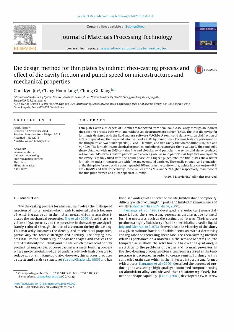
3.4. Microstructures of thin plate
Fig. 19(a) illustrates the microstructure of the sample formed
with a punchspeed of 300mm/s and with no graphite lubricant in
the cavity (condition 1). The microstructure shows that the solid
and liquid phases were severely segregated at positions F and E.
At position F (near gate), there were a few coarse dendrites from
coalescence;at position E (far from gate), therewere fewsolid par-
ticles. When there was high friction, the flow of solid particles was
difficult.Thus, a small part of thesolidphasemoved into thecavity,
and the liquid phase, which had better fluidity, filled the cavity. In
otherwords,high friction between the semi-solid material anddie
cavity cause a high degree of segregation between the solid and
liquid phases.
Fig. 19(b) and (c) shows the microstructures of the samples
formed at punch speeds of 300 and 30mm/s (conditions 1 and
2), respectively, with graphite lubricant in the cavity. The punch
speed of 300mm/s produced a finer grain size and denser distri-
bution of the solid phase than the punch speed of 30mm/s. At
30mm/s, the gap between solid particles was large because there
wasa lownumberofsolidparticleswithadiameterofover100m.
The porositywas high at position E. Fig. 20 shows thevolumefrac-
tion, equivalent diameter, and roundness of solid particles in the
samples formedat punch speedsof 300and 30mm/swithgraphite
lubricant. Forthe sampleformedat300mm/s,theequivalent diam-
eter, roundness, and volume fraction of solid particles at position
F were 65m, 1.25, and 45.5%, respectively. At position E, they
were 62m, 1.27, and 43.5%, respectively. For the sample formed
at 30mm/s, the equivalent diameter, roundness, and volume frac-
tion of the solid particles at position F were 72m, 1.45 and 36%,
respectively. At position E, they were 70m, 1.4, and 35%, respec-
tively. At position E, the solid phase was slightly smaller and more
globular, but the volume fractionwas lower than at position F. The
results show that themicrostructure of thin plate samples formed
at 300mm/s and 30mm/s were finer andmore globular compared
with themicrostructure of the semi-solid slurrywith EMS.
When a semi-solid slurrywas compressed with a punch, coarse
solid particles from coalescence broke off, and single solid parti-cles were deformed. Theseparticles and the liquid phase filled the
die cavity. Plastic deformation of the solid particles occurred by
forced convection during filling. A small and globular grain struc-
ture then formed. The moving velocity and distance of the solid
phase increase for smaller andmore globular grains.
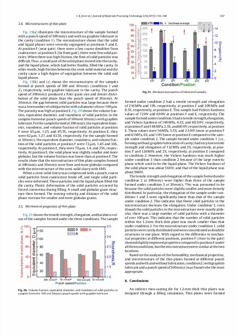
3.5. Mechanical properties of thin plate
Fig. 21 shows thetensile strength,elongation, andhardnessval-
ues of the samples formed under the three conditions. The sample
Fig. 20. Volume fraction, equivalent diameter, and roundness of solid particles in
samples formedat 300and30mm/s punchspeeds with graphite lubricant.
Fig. 21. Mechanical propertiesof fabricated samples.
formed under condition 2 had a tensile strength and elongation
of 216MPa and 10%, respectively, at position F and 209MPa and
8.5%, respectively, at position E. This sample hadVickers hardness
values of 72HV and 69HV at positions F and E, respectively. The
sample formedundercondition3hada tensile strength,elongation,and Vickers hardness of 160MPa, 4.5%, and 69.5HV, respectively,
atpositionF and148MPa, 2.5%, and68HV,respectively, atposition
E. These values were 56MPa, 5.5%, and 2.5HV lower at position F
and 61MPa, 6%, and 1HV lower at positionE compared to the sam-
ple under condition 2. The sample formed under condition 1 (i.e.,
formingwithoutgraphitelubrication of cavity)hadverylowtensile
strength and elongation of 132MPa and 2%, respectively, at posi-
tion F and 126MPa and 2%, respectively, at position E compared
to condition 2. However, the Vickers hardness was much higher
under condition 3 than condition 2 because of the large eutectic
phase which used to be the liquid phase. The Vickers hardness of
the solid phase was about 56HV, and that of the liquid phase was
about 98HV.
The tensile strengthandelongation of thesample formedundercondition 2 at 300mm/s were higher than those of the sample
formed under condition 3 at 30mm/s. This was presumed to be
because the solid particleswere slightly smaller andmore densely
distributed. In particular, the elongation of the sample under con-
ditions 1 and 3 were significantly lower than that of the sample
under condition 2. This indicates that fewer solid particles in the
microstructure decrease the elongation. Under condition 3, even
though the solid particles in themicrostructure were mostly glob-
ular, there was a large number of solid particles with a diameter
of over 100m. This indicates that the number of solid particles
within the 1.2mm thick thin plate was much smaller than that
under condition 2. For themicrostructure under condition 1, solid
particleswererarelydistributedandwereconcentratedasdendrite
structures in one place. With regard to the difference in mechan-ical properties at different positions, position F (close to the gate)
showedslightly improvedpropertiescomparedtopositionE under
all threeconditions,butthemicrostructureswere similarat thetwo
locations.
Based on theanalysis of the formability, mechanical properties,
and microstructure of the thin plates formed at different punch
speeds andwithandwithout lubrication,condition2 (withgraphite
lubricant and a punch speedof300mm/s)was found tobe themost
appropriate.
4. Conclusions
An indirect rheo-casting die for 1.2mm thick thin plates was
designed through a filling simulation. Thin plates were formed

7/18/2019 1-s2.0-S0924013615002022-main
http://slidepdf.com/reader/full/1-s20-s0924013615002022-main 13/13
168 C.K. Jin et al. / Journal of Materials Processing Technology 224 (2015) 156–168
under two friction conditions for thecavityand twopunchspeeds.
The effects of these parameters on the formability andmechanical
properties were analysed. The analytical and experimental results
are as follows:
(1) A fan-shapedgate allows the semi-solid slurry toevenlyfill the
entire thin cavity.
(2) Theincreasedflowratealongthecavity’s sidescanbecontrolled
by using overflows located at the sides of the cavity.
(3) The placement of overflows at the end of the cavity allows for
an even temperature and pressure (greater than atmospheric
pressure) distributionwithin the cavity.
(4) A semi-solid slurry having a solid fraction of 40% with fine
and globular solid particles can be obtained with an EMS. The
semi-solidwithout EMShadrosette particles andcoarser glob-
ular -Al particles. The equivalent diameter and roundness
of the solid particles of the semi-solid slurry with EMS were
about 75m and 1.5, respectively. Those of the solid parti-
cles of the semi-solid slurry with EMS were 110m and 2.3,
respectively.
(5) The cavity’s surface state experiences greater segregation
between the solid and liquid phases with increased friction.
When the frictionof the cavityis high, solid particles find it dif-
ficult tomove into thecavity, so theliquid phasewith relatively
good fluidity flows into the cavity.
(6) A higher punch speed for compression of the semi-solid
slurry produces better formability for the thin plate and
a microstructure with densely and evenly distributed solid
particles.
(7) The microstructure of formed thin plate was finer and more
globular compared with the microstructure of the semi-solid
slurry with EMS. Plastic deformation of the solid particles
occurred by forced convection during filling. A small and glob-
ular grain structure then formed. The moving velocity and
distance of the solid phase increase for smaller and more glob-
ular grains.
(8) When the semi-solid slurry was formed at a punch speed of
300mm/s with a graphite lubricant, a thin platewithout segre-
gationbetween thesolidandliquid phasesor other defectswas
obtained with a tensile strength of 216MPa and elongation of
10%.
Acknowledgements
This work was supported by the National Research Foun-
dation of Korea (NRF) grant funded by the Korea government
(No. 2013R1A1A2062759). Ministry of knowledge Economy (No.
20104010100540), This study was also supported by the Korea
Research Foundation (KRF) grant fundedby theKorea government
(MEST) (grant No. 2012-0001204).
References
Atkinson,H.V., 2005. Prog.Mater. Sci. 50, 341–412.Bae, J.W., Kim, T.W., Kang, C.G., 2007. J. Mater. Process. Technol. 191, 165–169.Chen, C.P., Tsao, C.-Y.A., 1997. Acta Mater.45, 1955–1968.Fan, Z., Fang, X., Ji, S., 2005. Mater. Sci. Eng., A 412, 298–306.Flemings,M.C., Riek, R.G., Young,K.P., 1976. Mater. Sci. Eng. 25, 103–117.
Ghomashchi, M.R., Vikhrov, A., 2000. J. Mater. Process. Technol. 101, 1–9. Ji, S., Fan, Z., Bevis,M.J., 2001. Mater. Sci. Eng., A 299, 210–217. Joly, P.A., Mehrabian, R., 1976. J. Mater. Sci. 11, 1393–1418.Kang, C.G., Bae, J.W., Kim, B.M., 2007. J. Mater. Process. Technol. 187–188, 344–348.Kang, C.G., Choi, J.S., Kim, K.H., 1999. J. Mater. Process. Technol. 88, 159–168.Kapranos, P., Ward, P.J., Atkinson, H.V., Kirkwood, D.H., 2000. Mater. Des. 21,
387–394.Kim, N.S., Kang, C.G., 2000. J. Mater. Process. Technol. 103, 237–246.Niu, X.P., Hu, B.H., Pinwill, I.,Li, H.,2000. J. Mater. Process. Technol. 105, 119–127.Pinsky, D.A., Charreyronv, P.O., Flemings, M.C., 1984. Metall. Mater. Trans., B 15B,
173–181.Seo, P.K., Youn, S.W., Kang,C.G.,2002. J. Mater. Process. Technol. 130–131,551–557.Seo, P.K., Kim, D.U., Kang, C.G., 2007. J. Mater. Sci. Eng., A 445–446, 20–30.Yue, T.M., Chadwick,G.A., 1996. J. Mater. Process Technol. 58, 302–307.
Related Documents