Electric Power Systems Research 108 (2014) 50–58 Contents lists available at ScienceDirect Electric Power Systems Research jou rn al hom epage: www.elsevier.com/locate/epsr Dynamic modeling and optimal control of DFIG wind energy systems using DFT and NSGA-II M. Zamanifar a,∗ , B. Fani b , M.E.H. Golshan a , H.R. Karshenas a a Department of Electrical and Computer Engineering, Isfahan University of Technology, Isfahan, Iran b Department of Electrical Engineering, Najafabad Branch, Islamic Azad University, Najafabad, Isfahan, Iran a r t i c l e i n f o Article history: Received 12 June 2013 Received in revised form 10 October 2013 Accepted 26 October 2013 Keywords: Dynamic modeling DFIG Optimized control DFT NSGA-II a b s t r a c t Once a doubly-fed induction generator (DFIG) is subjected to a disturbance by a change in the wind speed, the stator flux cannot change instantly. Under this condition, rotor back-EMF voltages reflect the effects of stator dynamics on rotor current dynamics, and have an important role on the oscillations of the rotor current. These oscillations decrease the DFIG system reliability and gear lifetime. Moreover, by focusing only on small signal analysis, the dynamic damping performance immediately following such disturbances is often degraded. Additional improvement in performance will be achieved if discrete Fourier transform (DFT) is used to quantify damping characteristic of the rotor current during changes of the operating points. This paper introduces an optimization technique based on non-dominated sorting genetic algorithm-II (NSGA-II) incorporating DFT analysis to achieve better control performance for DFIG system stability. Considering small signal stability, the main purpose of the control system in the present paper is to increase the system damping ratio as well as to guarantee enough stability margin. Eigenvalue analysis and time-domain simulations have been presented to demonstrate that the proposed optimi- zing method yields better control performance in comparison with one designed using mere eigenvalue relocation. © 2013 Elsevier B.V. All rights reserved. 1. Introduction In the development of wind turbine (WT) technologies, doubly- fed induction generators (DFIGs) are becoming the dominant type due to their advantages of variable speed operation, four-quadrant active and reactive power capabilities, independent control of their active and reactive output powers, high energy efficiency, and low size converters [1–4]. A diagram of a grid-connected DFIG-based wind energy generation system is shown in Fig. 1, which is com- posed of a wind turbine and gear-box, a wound rotor induction generator, a rotor-side converter (RSC) and a grid-side converter (GSC). Grid-side converter works at the grid frequency, leading or lagging in order to produce more or less reactive power while RSC works at different frequencies, depending on the blades speed [5,6]. Consequently, the speed can be varied while the operating fre- quency on the stator side remains constant. Rotor-side converter is used to control the generator speed and reactive power, whereas the GSC is connected to the grid through a grid-side filter and is used to control the DC-link voltage. ∗ Corresponding author. Tel.: +98 331 2291111; fax: + 98 331 2291017. E-mail address: [email protected] (M. Zamanifar). Due to the popularity of DFIG systems for wind energy gen- eration, control systems suitable for this application have been extensively investigated [7–12]. However, the most popular and practical control scheme of DFIGs is still field-oriented con- trol (FOC) based on proportional-integral (PI) controllers, which enables decoupled control of real and reactive powers [13–15]. FOC has been implemented in two ways. One way is to con- trol the DFIG with stator flux orientation, and the other is with air gap flux orientation. This paper deals with the analysis and improvement of transient performance in the DFIG modeled with the stator flux orientation. In this control scheme, the nonlin- ear cross coupling is eliminated with feed-forward compensation, after which the machine model becomes linear and PI control techniques can be applied. Thus, the active and reactive powers can be controlled by the quadrature and the direct rotor current components, respectively. Appropriate controller parameters are needed to achieve better control performance for DFIG system sta- bility. For this purpose, evolution algorithms have been used as optimization tools in the DFIG controller parameters design proce- dure [16–20]. For instance, in Ref. [17], genetic algorithm has been applied to optimize the controller parameters of the RSC, and hence, larger oscillations of the DC-link voltage cannot be avoided. Parti- cle swarm optimization has been also employed to find the optimal control parameters in order to achieve optimal control of DFIG 0378-7796/$ – see front matter © 2013 Elsevier B.V. All rights reserved. http://dx.doi.org/10.1016/j.epsr.2013.10.021

1-s2.0-S0378779613002927-main
Dec 07, 2015
electric
Welcome message from author
This document is posted to help you gain knowledge. Please leave a comment to let me know what you think about it! Share it to your friends and learn new things together.
Transcript
Du
Ma
b
a
ARRA
KDDODN
1
fdaaswpg(lwCqutu
0h
Electric Power Systems Research 108 (2014) 50– 58
Contents lists available at ScienceDirect
Electric Power Systems Research
jou rn al hom epage: www.elsev ier .com/ locate /epsr
ynamic modeling and optimal control of DFIG wind energy systemssing DFT and NSGA-II
. Zamanifara,∗, B. Fanib, M.E.H. Golshana, H.R. Karshenasa
Department of Electrical and Computer Engineering, Isfahan University of Technology, Isfahan, IranDepartment of Electrical Engineering, Najafabad Branch, Islamic Azad University, Najafabad, Isfahan, Iran
r t i c l e i n f o
rticle history:eceived 12 June 2013eceived in revised form 10 October 2013ccepted 26 October 2013
eywords:ynamic modelingFIGptimized control
a b s t r a c t
Once a doubly-fed induction generator (DFIG) is subjected to a disturbance by a change in the windspeed, the stator flux cannot change instantly. Under this condition, rotor back-EMF voltages reflect theeffects of stator dynamics on rotor current dynamics, and have an important role on the oscillations ofthe rotor current. These oscillations decrease the DFIG system reliability and gear lifetime. Moreover,by focusing only on small signal analysis, the dynamic damping performance immediately followingsuch disturbances is often degraded. Additional improvement in performance will be achieved if discreteFourier transform (DFT) is used to quantify damping characteristic of the rotor current during changes ofthe operating points. This paper introduces an optimization technique based on non-dominated sorting
FTSGA-II
genetic algorithm-II (NSGA-II) incorporating DFT analysis to achieve better control performance for DFIGsystem stability. Considering small signal stability, the main purpose of the control system in the presentpaper is to increase the system damping ratio as well as to guarantee enough stability margin. Eigenvalueanalysis and time-domain simulations have been presented to demonstrate that the proposed optimi-zing method yields better control performance in comparison with one designed using mere eigenvaluerelocation.
© 2013 Elsevier B.V. All rights reserved.
. Introduction
In the development of wind turbine (WT) technologies, doubly-ed induction generators (DFIGs) are becoming the dominant typeue to their advantages of variable speed operation, four-quadrantctive and reactive power capabilities, independent control of theirctive and reactive output powers, high energy efficiency, and lowize converters [1–4]. A diagram of a grid-connected DFIG-basedind energy generation system is shown in Fig. 1, which is com-osed of a wind turbine and gear-box, a wound rotor inductionenerator, a rotor-side converter (RSC) and a grid-side converterGSC). Grid-side converter works at the grid frequency, leading oragging in order to produce more or less reactive power while RSC
orks at different frequencies, depending on the blades speed [5,6].onsequently, the speed can be varied while the operating fre-uency on the stator side remains constant. Rotor-side converter issed to control the generator speed and reactive power, whereas
he GSC is connected to the grid through a grid-side filter and issed to control the DC-link voltage.∗ Corresponding author. Tel.: +98 331 2291111; fax: + 98 331 2291017.E-mail address: [email protected] (M. Zamanifar).
378-7796/$ – see front matter © 2013 Elsevier B.V. All rights reserved.ttp://dx.doi.org/10.1016/j.epsr.2013.10.021
Due to the popularity of DFIG systems for wind energy gen-eration, control systems suitable for this application have beenextensively investigated [7–12]. However, the most popular andpractical control scheme of DFIGs is still field-oriented con-trol (FOC) based on proportional-integral (PI) controllers, whichenables decoupled control of real and reactive powers [13–15].FOC has been implemented in two ways. One way is to con-trol the DFIG with stator flux orientation, and the other is withair gap flux orientation. This paper deals with the analysis andimprovement of transient performance in the DFIG modeled withthe stator flux orientation. In this control scheme, the nonlin-ear cross coupling is eliminated with feed-forward compensation,after which the machine model becomes linear and PI controltechniques can be applied. Thus, the active and reactive powerscan be controlled by the quadrature and the direct rotor currentcomponents, respectively. Appropriate controller parameters areneeded to achieve better control performance for DFIG system sta-bility. For this purpose, evolution algorithms have been used asoptimization tools in the DFIG controller parameters design proce-dure [16–20]. For instance, in Ref. [17], genetic algorithm has been
applied to optimize the controller parameters of the RSC, and hence,larger oscillations of the DC-link voltage cannot be avoided. Parti-cle swarm optimization has been also employed to find the optimalcontrol parameters in order to achieve optimal control of DFIG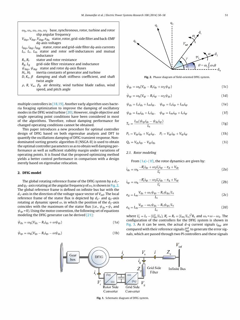
M. Zamanifar et al. / Electric Power Systems Research 108 (2014) 50– 58 51
ωb, ωs, ωr, ωt, ω2 base, synchronous, rotor, turbine and rotorslip angular frequency
Vdqs, Vdqr, Vdqg, edq stator, rotor, grid-side filter and back-EMFdq-axis voltages
idqs, idqr, idqg stator, rotor and grid-side filter dq-axis currentsLs, Lr, Lm stator and rotor self-inductances and mutual
inductanceRs, Rr stator and rotor resistanceRg, Lg grid-side filter resistance and inductance dqs, dqr stator and rotor dq-axis fluxesHr, Ht inertia constants of generator and turbineD, Ks, damping and shaft stiffness coefficient, and shaft
twist angle�, R, V�, ˇp air density, wind turbine blade radius, wind
mrmsoc
dqdtfoym
2
aTdrrc m
speed, and pitch angle
ultiple controllers in [18,19]. Another early algorithm uses bacte-ia foraging optimization to improve the damping of oscillatoryodes in the DFIG wind turbine [20]. However, single objective and
ingle operating point conditions have been considered in mostf the algorithms. Therefore, robust damping performance forhanged operating conditions cannot be obtained.
This paper introduces a new procedure for optimal controlleresign of DFIG based on both eigenvalue analysis and DFT touantify the oscillations damping of DFIG transient response. Non-ominated sorting genetic algorithm-II (NSGA-II) is used to obtainhe optimal controller parameters so as to obtain well damping per-ormance as well as sufficient stability margin under variations ofperating points. It is found that the proposed optimizing methodields a better control performance in comparison with a designerely based on eigenvalue relocation.
. DFIG model
The global rotating reference frame of the DFIG system by a d1-nd q1-axis rotating at the angular frequency of ωs is shown in Fig. 2.he global reference frame is defined on infinite bus bar with the1-axis in the direction of the voltage space vector of Vinf. The localeference frame of the stator flux is depicted by d2- and q2-axisotating at dynamic speed ω, in which the position of the d2-axisoincides with the maximum of the stator flux (i.e., ds = s andqs = 0). Using the motor convention, the following set of equationsodeling the DFIG generator can be derived [21]:
˙ds = ωb(Vds − Rsids + ω qs) (1a)
˙ qs = ωb(Vqs − Rsiqs − ω ds) (1b)
Fig. 1. Schematic diagra
Fig. 2. Phasor diagram of field-oriented DFIG system.
dr = ωb(Vdr − Rridr + ω2 qr) (1c)
qr = ωb(Vqr − Rriqr − ω2 dr) (1d)
ds = Lsids + Lmidr, qs = Lsiqs + Lmiqr (1e)
dr = Lmids + Lridr, qr = Lmiqs + Lriqr (1f)
Te = Lm( qsidr − dsiqr)Ls
(1g)
Ps = Vdridr + Vqriqr, Pr = Vdridr + Vqriqr (1h)
Qs = Vdsiqs − Vqsids (1i)
2.1. Rotor modeling
From (1a)–(1f), the rotor dynamics are given by:
idr = ωb−R′
ridr + ω2L′riqr − ed + Vdr
L′r(2a)
iqr = ωb−R′
riqr − ω2L′ridr − eq + Vqr
L′r(2b)
ed = LmVds + ωr qs − Rs ds/Ls
Ls(2c)
eq = LmVqs − ωr ds − Rs qs/Ls
Ls(2d)
where L′r = Lr − (L2m/Ls), R′
r = Rr + (Lm/Ls)2Rs and ωr = ω − ω2. The
configuration of the controllers for the DFIG system is shown inFig. 3. As it can be seen, the actual d–q current signals idqr arecompared with their reference signals irefdqr to generate the error sig-nals, which are passed through two PI controllers and these signals
m of DFIG system.

52 M. Zamanifar et al. / Electric Power Systems Research 108 (2014) 50– 58
rrent
aav
V
V
x
x
wgfls
s(
Q
pQ
Q
Q
c
i
i
x
Fig. 3. DFIG control loops: rotor current, grid filter cu
re then compensated by the corresponding cross-coupling termsnd back-EMF (electromotive force) voltages edq to form the rotoroltage signals given as follows:
dr = K idrP (iref
dr − idr) + x5 − ω2L′riqr + ed (3a)
qr = K iqrP (iref
qr − iqr) + x6 + ω2L′ridr + eq (3b)
˙ 5 = K idrI (iref
dr − idr) (3c)
˙ 6 = K iqrI (iref
qr − iqr) (3d)
here K idrP , K iqr
P and K idrI , K iqr
I are the proportional and inte-rating gains of the rotor current control loops. With the statorux-orientated reference frame, iref
dr is calculated from the desiredtator-side reactive power Q ref
s , while irefqr is generated from the
peed control loop [5]. Once in steady state (i.e., sd = 0 and ω = ωs),1) leads to:
s = ωs ds(Lmidr − ds)Ls
(4)
In this equation, Qs is divided into two parts: the magnetizingart Qs,magn, and the reactive power part exchanged with the grids,gen. Suppose that ω = ωs and Rs = 0, then:
s,magn = − V2s
ωsLs(5a)
s,gen = VsidrLm
Ls(5b)
The reactive power control loop is depicted in Fig. 4 and theorresponding equations are described by:
refqr = −K�r
P (ωrefr − ωr) − x7 (6a)
refdr = Kpf
P (Q refs − Qs) + x8 (6b)
˙ 7 = KωrI (ωref
r − ωr) (6c)
Fig. 4. Reactive powe
, speed, reactive power and dc voltage control loops.
x8 = KpfI (Q ref
s − Qs) (6d)
The reactive power reference value is derived from the activepower reference and the desired value of the power factor [22].During the entire test, Q ref
s is set to zero.
2.2. Grid-side filter modeling
The dq model of the GSC and filter are:
idg = ωb−Rgidg + ωLgiqg − Vdg + Vds
Lg(7a)
iqg = ωb−Rgiqg − ωLgidg − Vqg + Vqs
Lg(7b)
Considering the grid-side filter current controllers to beproportional-integral (PI) and under compensation of cross-coupling terms and stator voltages, Vdqs, the dq grid voltageequations could be stated as:
Vdg = −K idgP (iref
dg − idg) − x14 + ωLgiqg + Vds (8a)
Vqg = −K iqgP (iref
qg − iqg) − x15 − ωLgidg + Vqs (8b)
x14 = K idgI (iref
dg − idg) (8c)
x15 = K iqgI (iref
qg − iqg) (8d)
where irefdg , iref
qg are dq grid-side filter current references. irefdg is set
to zero, while irefqg is generated from the DC voltage control loop as
follows:
ref Vdc ref
iqg = KP (Vdc − Vdc ) + x17 (9a)x17 = KVdcI (Vdc − V ref
dc ) (9b)
r control loop.
M. Zamanifar et al. / Electric Power Systems Research 108 (2014) 50– 58 53
ed and
2
Dp
ω
ω
ˇ
w0t
C
�
�
vsAttmtˇttmo
ˇ
Fig. 5. (a) Mechanical power versus wind spe
.3. Drive train modeling
To represent the electrical and mechanical interaction betweenFIG and WT in transient stability studies, the two-mass model asresented in [14] is considered as:
˙ r = Te + Tsh
2Hr(10a)
˙ t = Tm − Tsh
2Ht(10b)
˙ = ωb(ωt − ωr) (10c)
here Tsh = Ks + D(ωt − ωr), Te = − Lm dsiqr/Ls and Tm =.5��R2CpV3
ω/SBωt are the shaft, electromagnetic and mechanicalorques, respectively. The power coefficient Cp is given as:
p = 0.22(
116�i
− 0.4ˇp − 5)e−12.5/�i (11a)
i =(
1� + 0.08ˇp
− 0.035
ˇp3 + 1
)−1
(11b)
= ωtR
V�(11c)
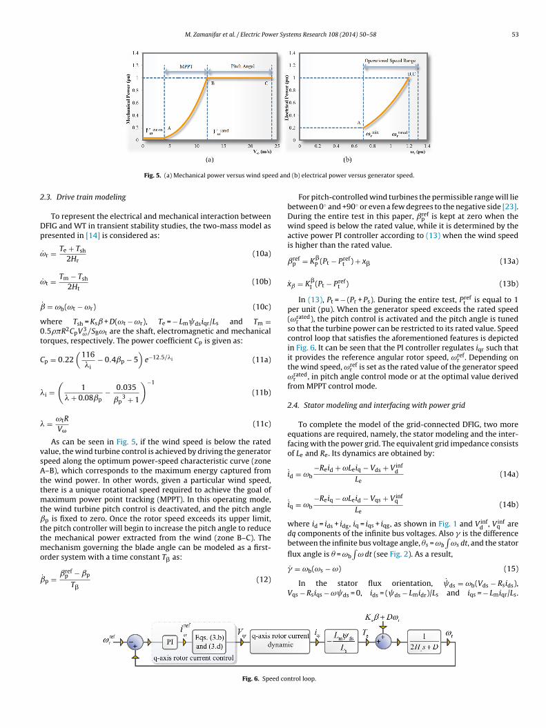
As can be seen in Fig. 5, if the wind speed is below the ratedalue, the wind turbine control is achieved by driving the generatorpeed along the optimum power-speed characteristic curve (zone–B), which corresponds to the maximum energy captured from
he wind power. In other words, given a particular wind speed,here is a unique rotational speed required to achieve the goal of
aximum power point tracking (MPPT). In this operating mode,he wind turbine pitch control is deactivated, and the pitch anglep is fixed to zero. Once the rotor speed exceeds its upper limit,
he pitch controller will begin to increase the pitch angle to reducehe mechanical power extracted from the wind (zone B–C). The
echanism governing the blade angle can be modeled as a first-rder system with a time constant T as:
�˙ p = ˇrefp − ˇp
T�(12)
Fig. 6. Speed con
(b) electrical power versus generator speed.
For pitch-controlled wind turbines the permissible range will liebetween 0◦ and +90◦ or even a few degrees to the negative side [23].During the entire test in this paper, ˇref
p is kept at zero when thewind speed is below the rated value, while it is determined by theactive power PI controller according to (13) when the wind speedis higher than the rated value.
ˇrefp = K�
P (Pt − Preft ) + x� (13a)
xˇ = K�I (Pt − Pref
t ) (13b)
In (13), Pt = − (Pr + Ps). During the entire test, Preft is equal to 1
per unit (pu). When the generator speed exceeds the rated speed(ωrated
r ), the pitch control is activated and the pitch angle is tunedso that the turbine power can be restricted to its rated value. Speedcontrol loop that satisfies the aforementioned features is depictedin Fig. 6. It can be seen that the PI controller regulates iqr such thatit provides the reference angular rotor speed, ωref
r . Depending onthe wind speed, ωref
r is set as the rated value of the generator speedωrated
r , in pitch angle control mode or at the optimal value derivedfrom MPPT control mode.
2.4. Stator modeling and interfacing with power grid
To complete the model of the grid-connected DFIG, two moreequations are required, namely, the stator modeling and the inter-facing with the power grid. The equivalent grid impedance consistsof Le and Re. Its dynamics are obtained by:
id = ωb−Reid + ωLeiq − Vds + V inf
dLe
(14a)
iq = ωb−Reiq − ωLeid − Vqs + V inf
q
Le(14b)
where id = ids + idg, iq = iqs + iqg, as shown in Fig. 1 and V infd , V inf
q aredq components of the infinite bus voltages. Also � is the differencebetween the infinite bus voltage angle, �s = ωb
∫ωs dt, and the stator
flux angle is � = ωb
∫ω dt (see Fig. 2). As a result,
� = ωb(ωs − ω) (15)
In the stator flux orientation, ds = ωb(Vds − Rsids),Vqs − Rsiqs − ω ds = 0, ids = ( ds − Lmidr)/Ls and iqs = − Lmiqr/Ls.
trol loop.

5 er Sys
Td
(Lm id
ω
p
2
p
V
wtIsm
3p
lnoDotiloffscclroftDtDistbffgs
4 M. Zamanifar et al. / Electric Pow
hen, from (14a), the d-axis stator flux dynamic equation isescribed by:
˙ds = ωb
[(Rs + Re)(Lmidr − ds) − ReLsidg + (Lsiqg − Lmiqr)Leω + Le(
Ls + Le
Moreover, from (14b) it turns out:
= LsωbVinfq − ReLsωbiqg + (Rs + Re)Lmωbiqr + Le(Lm iqr − Ls iqg)
(Ls + Le)ωb ds + Leωb(Lsidg − Lmidr)(17)
Eqs. (15)–(17) constitute the basis for interfacing DFIG with theower grid.
.5. DC-link capacitor modeling
The DC-link model can be deduced from the balance of realower at the converter DC-link node as given by [14]:
˙ dc = ωbPr − Pg
CVdc(18)
here Vdc is the DC-link voltage, and Pg(= Vdgidg + Vqgiqg) and Pr arehe powers supplied to the GSC and the rotor circuit, respectively.t is noted that for a phase-locked loop (PLL) controller the corre-ponding bandwidth is relatively large and can be ignored in theodel [24].
. Behavior analysis of DFIGs during changes of operatingoints
The stator modes have the lowest damping ratios but their oscil-ation frequencies are high, and hence, usually their dynamics iseglected in the literature. However, during the variations of theperating points, these modes could have significant effects on theFIG transient behavior and they should be considered during theptimal design. According to the principle of constant flux linkages,he stator flux cannot change instantaneously when the generators subjected to a disturbance by a change in the wind speed. Thiseads to a DC component in the stator flux, which appears as anscillatory term when transferred into the synchronous referencerame with a corresponding natural frequency near the networkrequency. Transient response of the stator flux can be divided intoteady state and oscillatory parts, which guarantees that no dis-ontinuities appear in the stator flux when the operating pointhanges [25]. According to (4), the oscillatory flux induces an oscil-atory component in the d-axis rotor current (idr), which can beelatively large with a low damping ratio. However, by focusingnly on the small signal condition, the damping characteristic of idrollowing a change in the operating point will be degraded. Addi-ional improvement in DFIG dynamic performance is achievable ifFT analysis is also utilized to quantify damping characteristic of
he rotor current. This paper focuses on the optimal tuning of the
FIG controller parameters, which can improve the system damp-ng performance immediately following a large disturbance. Threeub-objective functions are applied for the optimal tuning of allhe controller parameters. One is to use an optimization techniqueased on DFT analysis, which improves the rotor current dynamicollowing a change in the operating point. Moreover, the otherunctions are to increase the system damping ratio as well as touarantee enough stability margin, typically found in traditionalmall signal stability analysis.
tems Research 108 (2014) 50– 58
r − Ls idg)/ωb) + LsV infd ]
(16)
4. Optimization model
4.1. Eigenvalue-based objective functions
The model of DFIG WT can be represented by a set of ordinarydifferential equations as:
x = f (x, u) (19)
where x and u are the vectors of DFIG WT system state and inputvariables, respectively. They are defined as x = [ ds, � , idr, iqr, x5,x6, x7, x8, ωr, ˇ, ωt, idg, iqg, x14, x15, Vdc, x17, xˇ, ˇp]T and u =
u = [V refdc , Vinf , V�, ωref
r , Q refs , iref
dg ]T. Linearizing (19) around an oper-
ation point, the system state matrix A can be calculated. To increasethe DFIG system damping ratio as well as to guarantee sufficientstability margin, the parameters of the PI controller may be selectedto minimize the following eigenvalue-based objective functions.
J1(X) = 1Min �i
∀i
(20)
J2(X) = Max∀ii (21)
where �i and i are the damping factor and the real part of theith eigenvalue, respectively, and X is the vector of PI controllerparameters. The objective function J1 makes sure that the minimumdamped eigenvalue is heavily damped and the system small signalstability is ensured. The optimization aims to minimize J2 in orderto shift all the eigenvalues as far to the left of the left hand side ofthe complex plane as possible. These objective functions consideronly an operating point, and hence, sufficient stability margin forchanged operating conditions cannot be obtained.
4.2. Application of DFT for damping enhancement
Additional improvement in performance will be achieved if DFTis utilized for estimating the damping factor of the rotor currentduring changes of operating points. It has been investigated in Ref.[26] that well-damped oscillation signals have significantly loweramplitude in the frequency domain. Moreover, to achieve accu-rate damping factor estimates, the long data windows should beselected. The window length in this study is 100 cycles (1.67 s in60 Hz). As mentioned in the previous section, once the operatingpoint changes, an oscillatory component in the d-axis rotor currentwill be induced at a frequency of 60 Hz. It follows that minimizationof the fundamental components of the d-axis rotor current willresult in a well-damped DFIG system response in the time domain.Thus, the parameters of PI controller may be selected to minimizethe following DFT based objective function.
J3(X) = |Idr[1]| (22)
The above objective function along with J1 and J2 enhance thesmall signal stability at different operating points. Fig. 7 shows theoptimization procedure of the tuning of DFIG control system.
5. Optimization using NSGA-II
Pareto-based fitness assignment was first proposed by Gold-berg [27]. The idea is to assign equal probability of reproductionto all non-dominated individuals in the population. The method

M. Zamanifar et al. / Electric Power Systems Research 108 (2014) 50– 58 55
ains t
crdaioap
5
KsK
KrtmKt
5
o
J
ie
5
Ppoa
wt
Fig. 7. Offline PI g
onsists of assigning rank 1 to the non-dominated individuals andemoving them from contention, then finding a new set of non-ominated individuals, ranked 2, and so forth. NSGA-II differs from
simple genetic algorithm only in the way the selection operations performed. The superiority of NSGA-II lies in the way multiplebjectives are reduced to a single fitness measured by the cre-tion of number of fronts, sorted according to non-domination. Therocedure of the optimization is designed as follows:
.1. Step one: Initialization
In Section 2, there are 14 parameters, K idrP , K iqr
P , K idrI , K iqr
I , KpfP , Kpf
I ,�rP , K�r
I , K idgP , K iqg
P , K idgI , K iqg
I , KVdcP and KVdc
I for the controllers of WTystem in MPPT control zone and two more parameters, namely,ˇP and KˇI in pitch angle control zone. It is supposed that K idr
P =iqrP , K idr
I = K iqrI , K idg
P = K iqgP , K idg
I = K iqgI . The process is started by
andomly generating N individuals of the initial population aroundhe original values, which could be obtained by the poles placement
ethodology [17]. Then, the lower and upper bounds, Kmin andmax of the parameters should be specified to define the range ofhe searching space.
.2. Step two: Evaluation
With the sub-objective functions defined in Section 4, the multi-bjective optimization problem can be now formulated as:
= Min{J1, J2, J3} (23)
Considering the small signal stability, the main purpose of (23)s to increase the system damping ratio as well as to guaranteenough stability margin.
.3. Step three: The best compromise solution
In order to choose the optimal controller parameter among theareto optimal set, a Fuzzy-based approach is employed in theresent paper. The kth objective function of a solution in a Paretoptimal set Jk is represented by a membership function k defineds:
k =
⎧⎪⎪⎨⎪⎪⎩
1 Jk ≤ Jk,min
Jk,max − JkJk,max − Jk,min
Jk,min < Jk ≤ Jk,max
0 Jk ≥ Jk,max
(24)
here Jk,max and Jk,min are the maximum and minimum values ofhe kth objective function.
For each solution i, the membership function is calculated as:
i =∑n
k=1ik∑m
i=1
∑nk=1
ik
(25)
uning procedure.
where n is the number of objective functions and m is the numberof solutions. The solution having the maximum value of i is thebest-compromised solution.
6. Simulation and results
In this section, some simulations are presented to confirm theimprovement in control performance of the DFIG system with theproposed optimized parameters. The studies are done on the singlemachine infinite bus power system shown in Fig. 3, with the systemparameters given in Table 1.
6.1. Eigenvalue analysis
Eigenvalue analysis of the DFIG wind turbine system is dis-cussed in the following, where the focus is on participation factor,frequency, and damping ratio analysis. Using the system parame-ters presented in Table 1 and controller gains listed in AppendixA, the system modes and corresponding variables with the modaloscillation frequency, damping ratio and highest participation fac-tors are obtained as in Table 2. It can be seen that the system isstable, since all the eigenvalues have negative real parts. In par-ticular, there are four modes of oscillation. The modes �12,13 areassociated with the mechanical variables x7, ωt, ˇp. These modesare weakly damped. The second slowest modes �7,8 are electrome-chanical modes associated with the rotor variables ωr and ˇ. Thethird oscillating modes �3,4 are electrical modes. Stator variables ds and � have the highest contributions in these modes. The statormodes have the lowest damping ratios, but their oscillation fre-quencies are high, and hence, usually their dynamics is neglected.But, as mentioned earlier in Section 3, once the operating pointchanges, the rotor back-EMF voltages reflect the effects of statordynamics on rotor current dynamics, and have an important roleon oscillations of the rotor current. As can be seen in Table 2, themode �1 associated with idr is a non-oscillatory mode.
6.2. Time-domain simulations
In this paper, three methods for setting the DFIG parameters areconsidered.
Method one: The PI controller parameters are tuned through poleplacement method [17].
Method two: The parameters are optimized through eigenvalue-based objective functions.
Method three: The controller parameters are obtained throughthe proposed method.
The controller parameters are presented in Appendices A–C
for methods one to three, respectively. The coordinated tuningof the parameters is performed by NSGA-II at a base wind speedof 6 m/s. Furthermore, to improve the system damping perfor-mance, the response of DFIG system under variation of 15% in wind
56 M. Zamanifar et al. / Electric Power Systems Research 108 (2014) 50– 58
Table 1Parameters of the 1.76-MVA, 575-V, 60-Hz DFIG WT.
P.U. system Vb = 575 V, Sb = 1.76 MVA, fb = 60 Hz, ωb = 377 rad/s, ωs = 1 puWind turbine Ht = 4.3 s, Hr = 0.75 s, ks = 0.6 pu/elec.rad, D = 1.2 pu, � = 1.225 kg/m3, R = 34.93 m, ωrated
r = 1.2 puDFIG Rs = 0.00706 pu, Ls = 3.07 pu, Lm = 2.9 pu, Rr = 0.005 pu, Lr = 3.056 puConverter C = 12.72 pu, Vdc = 1200 VGrid filter impedance Rg = 0.003 pu, Lg = 0.3 puNetwork impedance Re = 0.05 pu, Le = 0.3 pu
Table 2Eigenvalues and participation factors (Vω = 15 m/s).
System mode Oscillation frequency Damping ratio State variables with highest participation factors (%)
�1 = −1193 – 1 Rotor electrical idr = 94%�2 = −1210 – 1 Filter electrical iqg = 92%�3,4 = −3.1 ± j368 58.5 0.01 Stator electrical ds = 50%, � = 49%�5 = −602 – 1 Rotor electrical iqr = 99%�6 = −63.5 – 1 DC-link Vdc = 94%�7,8 = −2.83 ± j12.96 2.06 0.21 Rotor electromechanical ωr = 43%, = 49%�9 = −1259 – 1 Filter electrical idg = 99%�10 = −1.94 – 1 q-Axis rotor current control x6 = 97%�11 = −1.97 – 1 d-Axis rotor current control x5 = 99%�12,13 = −0.38 ± j0.4 0.06 0.69 Speed control and turbine mechanical and pitch angle control x7 = 25%, ωt = 38%, ˇp = 24%�14 = −0.08 – 1 Active power control and pitch angle control x� = 76%, ˇp = 20%�15 = −0.21 – 1 Speed control and pitch angle control x7 = 38%, ˇp = 54%�16 = −0.5 – 1 DC-link control x17 = 99%
e powlter clter c
sictam
iohD
�17 = −0.49 – 1 Reactiv�18 = −1 – 1 q-Axis fi�19 = −1 – 1 d-Axis fi
peed is considered for evaluating the DFT-based objective functionncluded in method three. In the following, dynamic simulations arearried out to observe the response of the DFIG system under a dis-urbance by a change in the wind speed. The system is subjected to
disturbance by a change in the wind speed at t = 0.2 s, when V� = 9/s. It amounts to 12% variation in the wind speed.The dynamic of slip speed is simulated and the result is shown
n Fig. 8(a). In the following analysis, light blue, dark blue andrange lines are related to methods one to three, respectively. Itas been investigated in Ref. [22] that the nature of instability inFIG systems is basically different from the rotor angle instability of
Fig. 8. Transient response of (a) generator slip speed, (b) stator fl
er control x8 = 99%urrent control x15 = 99%urrent control x14 = 99%
synchronous generators. Normally, the DFIG speed range is about±30% around the synchronous speed. If the generator speed vio-lates the above limits, the converter cannot handle the slip powerand the generator may become unstable. As it can be observed inFig. 8(a), although the generator slip speed is within the allowablerange in all methods, the lowest growth of the generator speedoccurs in method three. Also, Fig. 8(b) and (c) shows the stator flux
linkage and the rotor current oscillation. As expected, by using theproposed method, a sensible reduction on the stator flux linkageand the rotor current oscillation is observed when DFIG systemis subject to a disturbance. Moreover, it is important to study theux linkage, (c) d-axis rotor current, and (d) DC-link voltage.
M. Zamanifar et al. / Electric Power Systems Research 108 (2014) 50– 58 57
F al volr
orhtomFflbmtostaa
7
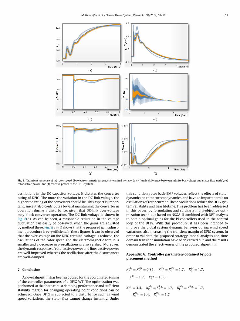
opsas
ig. 9. Transient response of (a) rotor speed, (b) electromagnetic torque, (c) terminotor active power, and (f) reactive power to the DFIG system.
scillations in the DC capacitor voltage. It dictates the converterating of DFIG. The more the variation in the DC-link voltage, theigher the rating of the converters should be. This aspect is impor-ant, since it also contributes toward maintaining the converter inperation during a disturbance, given that DC-link over-voltageay block converter operation. The DC-link voltage is shown in
ig. 8(d). As can be seen, a reasonable reduction in the voltageuctuation can easily be observed, when the gains are adjustedy method three. Fig. 9(a)–(f) shows that the proposed gain adjust-ent procedure is very efficient. In these figures, it can be observed
hat the over-voltage on the DFIG terminal voltage is reduced, thescillations of the rotor speed and the electromagnetic torque ismaller and a decrease in � oscillations is also verified. Moreover,he dynamic response of rotor active power and line reactive powerre well improved whereas the oscillations after the disturbancesre well-damped.
. Conclusion
A novel algorithm has been proposed for the coordinated tuningf the controller parameters of a DFIG WT. The optimization was
erformed so that both robust damping performance and sufficienttability margin for changing operating point conditions can bechieved. Once DFIG is subjected to a disturbance such as windpeed variations, the stator flux cannot change instantly. Undertage, (d) � (angle difference between infinite bus voltage and stator flux angle), (e)
this condition, rotor back-EMF voltages reflect the effects of statordynamics on rotor current dynamics, and have an important role onoscillations of rotor current. These oscillations reduce the DFIG sys-tem reliability and gear lifetime. This problem has been addressedin this paper, by formulating and solving a multi-objective opti-mization technique based on NSGA-II combined with DFT analysisto obtain optimal gains for the PI controllers used in the controlloop of the DFIG. With this procedure, it has been intended toimprove the global system dynamic behavior during wind speedvariations, also increasing the transient margin of DFIG system. Inorder to validate the proposed strategy, modal analysis and timedomain transient simulation have been carried out, and the resultsdemonstrated the effectiveness of the proposed algorithm.
Appendix A. Controller parameters obtained by poleplacement method
K idrP = K iqr
P = 0.85, K idrI = K iqr
I = 1.7, KpfP = 1.7,
KpfI = 1.7, K�r
P = 13.6
K�rI = 3.4, K idg
P = K iqgP = 1.7, K idg
I = K iqgI = 1.7,
KVdcP = 3.4, KVdc
I = 1.7

5 er Sys
Ao
K
K
Ao
K
K
R
[
[
[
[
[
[
[
[
[
[
[
[[
[
[
[
8 M. Zamanifar et al. / Electric Pow
ppendix B. Controller parameters obtained by firstptimization method
idrP = K iqr
P = 1.52, K idrI = K iqr
I = 1.21, KpfP = 0.74,
KpfI = 2.54, K�r
P = 10.3
�rI = 2.52, K idg
P = K iqgP = 2.04, K idg
I = K iqgI = 2.36,
KVdcP = 3.36, KVdc
I = 2.1
ppendix C. Controller parameters obtained by secondptimization method
idrP = K iqr
P = 0.14, K idrI = K iqr
I = 2.16, KpfP = 0.74,
KpfI = 2.71, K�r
P = 9.44
�rI = 2.45, K idg
P = K iqgP = 1.41, K idg
I = K iqgI = 1.44,
KVdcP = 3.26, KVdc
I = 2.06
eferences
[1] R. Cardenas, R. Pena, S. Alepuz, G. Asher, Overview of control systems for theoperation of DFIGs in wind energy applications, IEEE Transactions on IndustrialElectronics 60 (2013) 2776–2797.
[2] M. Tazil, V. Kumar, R.C. Bansal, S. Kong, Z.Y. Dong, W. Freitas, H.D. Mathur,Three-phase doubly fed induction generators: an overview, IET Electric PowerApplications 4 (2010) 75–89.
[3] G.D. Marques, D.M. Sousa, Air-gap-power-vector-based sensorless method forDFIG control without flux estimator, IEEE Transactions on Industrial Electronics58 (2011) 4717–4726.
[4] M.Z. Kamh, R. Iravani, Three-phase steady-state model of type-3 wind genera-tion unit-part I: mathematical models, IEEE Transactions on Sustainable Energy2 (2011) 477–486.
[5] V. Akhmatov, Analysis of dynamic behavior of electric power systems withlarge amount of wind power, Technical University of Denmark, Kgs, Lyngby,Denmark, 2003 (PhD thesis).
[6] G.D. Marques, D.M. Sousa, Stator flux active damping methods for field-
oriented doubly fed induction generator, IEEE Transactions on EnergyConversion 27 (2012) 799–806.[7] D.C. Gaona, L.M. Goytia, O.A. Lara, Fault ride-through improvement of DFIG-WTby integrating a two-degree-of-freedom internal model control, IEEE Transac-tions on Industrial Electronics 60 (2013) 1133–1145.
[
[
tems Research 108 (2014) 50– 58
[8] Z.S. Zhang, Y.Z. Sun, J. Lin, G.J. Li, Coordinated frequency regulation by dou-bly fed induction generator-based wind power plants, IET Renewable PowerGeneration 6 (2012) 38–47.
[9] A.J.S. Filho, E.R. Filho, Model-based predictive control applied to the doubly-fed induction generator direct power control, IEEE Transactions on SustainableEnergy 3 (2012) 398–406.
10] A.J.S. Filho, M.E.D.O. Filho, E.R. Filho, A predictive power control for wind energy,IEEE Transactions on Sustainable Energy 2 (2011) 97–105.
11] S.Z. Chen, N.C. Cheung, K.C. Wong, J. Wu, Integral variable structure directtorque control of doubly fed induction generator, IET Renewable Power Gen-eration 5 (2010) 18–25.
12] J.P.D. Costa, H. Pinheiro, T. Denger, G. Arnold, Robust controller for DFIGs ofgrid-connected wind turbines, IEEE Transactions on Industrial Electronics 58(2011) 4023–4038.
13] S. Li, T.A. Haskew, K.A. Williams, R.P. Swatloski, Control of DFIG wind turbinewith direct-current vector control configuration, IEEE Transactions on Sustain-able Energy 3 (2012) 1–11.
14] L. Yang, Z. Xu, J. Ostergaard, Z.Y. Dong, K.P. Wong, X. Ma, Oscillatory stabilityand eigenvalue sensitivity analysis of a DFIG WT system, IEEE Transactions onEnergy Conversion 26 (2011) 328–339.
15] L. Yang, Z. Xu, J. Ostergaard, Z.Y. Dong, K.P. Wong, Advanced control strategy ofDFIG wind turbines for power system fault ride through, IEEE Transactions onPower Systems 27 (2012) 713–722.
16] L. Yang, G.Y. Yang, Z. Xu, Z.Y. Dong, K.P. Wong, X. Ma, Optimal controllerdesign of a doubly-fed induction generator wind turbine system for small signalstability enhancement, IET Generation, Transmission & Distribution 4 (2010)579–597.
17] J.P.A. Vieira, M.V.A. Nunes, U.H. Bezerra, A.C. Nascimento, Designing optimalcontrollers for DFIGs using a genetic algorithm, IET Generation, Transmission& Distribution 3 (2009) 472–484.
18] Y. Tang, P. Ju, H. He, C. Qin, F. Wu, Optimized control of DFIG-based windgeneration using sensitivity analysis and particle swarm optimization, IEEETransactions on Smart Grid 4 (2012) 1–12.
19] F. Wu, X.P. Zhang, K. Godfrey, P. Ju, Small signal stability analysis and optimalcontrol of a wind turbine with doubly fed induction generator, IET Generation,Transmission & Distribution 1 (2007) 751–760.
20] Y. Mishra, S. Mishra, M. Tripath, N. Senroy, Z. Dong, Improving stability of aDFIG-based wind power system with tuned damping controller, IEEE Transac-tions on Energy Conversion 24 (2009) 650–660.
21] P.C. Krause, Analysis of Electric Machinery, McGraw-Hill, New York, 1986.22] M. Rahimi, M. Parniani, Dynamic behavior analysis of doubly-fed induction gen-
erator wind turbines – the influence of rotor and speed controller parameters,Electrical Power and Energy Systems 32 (2010) 464–477.
23] T. Ackermann, Wind Power in Power Systems, John Wiley & Sons, New York,NY, USA, 2005.
24] B. Pokharel, Modeling, control and analysis of a doubly fed induction generatorbased wind turbine system with voltage regulation, Tennessee TechnologicalUniversity, USA, 2011 (MS thesis).
25] P.S. Flannery, G. Venkataramanan, A fault tolerant DFIG wind turbine using aparallel grid side rectifier and series grid side converter, IEEE Transactions onPower Electronics 23 (2008) 1126–1134.
26] E. Brigham, The Fast Fourier Transform and its Application, Prentice-Hall, Engle-wood Cliffs, 1988.
27] S. Panda, Multi-objective PID controller tuning for a FACTS-based damping sta-bilizer using non-dominated sorting genetic algorithm-II, Electrical Power andEnergy Systems 33 (2011) 1296–1308.
Related Documents