Determination of adequate regenerator for a Gamma-type Stirling engine Ramla Gheith a , Fethi Aloui b,⇑ , Sassi Ben Nasrallah a a Université de Monastir, École Nationale d’Ingénieurs de Monastir, Laboratoire LESTE, Avenue Ibn El Jazzar 5019, Monastir, Tunisia b University of Lille North of France, UVHC, LAMIH CNRS UMR 8201, Campus Le Mont Houy, F-59313 Valenciennes Cedex 9, France highlights A Gamma-Stirling engine is investigated to optimize its operation. A stainless steel of a porosity of 85% was used as material for the regenerator. Asymmetry of heat transfer inside regenerator’s consumes a part of produced energy. Central composite rotatable design was adopted to minimize this phenomenon. The heating temperature is a most significant factor in the study. article info Article history: Received 24 July 2013 Received in revised form 20 October 2014 Accepted 11 November 2014 Available online 11 December 2014 Keywords: Stirling engine Regenerator Constituting material Porosity Optimization abstract This paper deals with an optimization of the Stirling engine regenerator’s. Firstly, different materials are experimented (Stainless Steel, Copper, aluminum and Monel 400). The engine performances and the state of each material after 15 h of use are considered. The Stainless steel was the material that best satisfies these two conditions. Five regenerators in stainless steel with different porosities were manufactured and experimented (95%, 90%, 85%, 80% and 75%). Porosity that gives the best trade-off between maximizing the engine brake power, maximizing the heat transfer and minimizing the pressure drops, was retained. Thus, the regenerator in stainless steel with porosity of 85% was considered as the most suitable matrix maximizing the Stirling engine performances and minimizing heat and friction losses. Ó 2014 Elsevier Ltd. All rights reserved. 1. Introduction Stirling engine regenerators are very complex to modeling and to designing. It will require a large number of equations to describe their thermodynamic operation. Since it is a balancing act of sev- eral factors, some researches have proposed the best regenerator qualities [1–4] allowing optimal Stirling engine performances. It must have: – High thermal capacity to minimize temperature variation [5], – high thermal conductivity to minimize temperature gradients [6], – large surface area to minimize temperature differences between the regenerator and the working fluid [7], – small dead volume with dense matrix to maximize pressure variation [7,8a,b], – a highly porous matrix with minimum resistance to flow [9,10]. Evidently, it is impossible to satisfy all these properties at one time; thus any regenerator must be a compromise [3]. Chen et al. [11] has demonstrated that the insertion of a metal- lic matrix helps the system to become more stable to possible dis- turbances in the mass flow rate supply of hot fluid. Timoumi et al. [12] studied the performances of a Stirling engine regenerator for porosity ranging from 0.6112 to 0.9122 by varying its correspond- ing wire mesh from 0.0090 to 0.0035. The decrease in mesh poros- ity leads to the highest friction factor and pressure drop. In spite of the higher pressure drop we have better power and thermal effi- ciency because we have better heat transfer. Chang and Yang [13] studied a Ross Yoke drive engine for solar applications. They proposed a detailed analysis of the influence of the regenerator parameters on the engine performances. An increase in matrices http://dx.doi.org/10.1016/j.apenergy.2014.11.011 0306-2619/Ó 2014 Elsevier Ltd. All rights reserved. ⇑ Corresponding author at: University of Lille North of France, UVHC, LAMIH CNRS UMR 8201, Campus Le Mont Houy, F-59313 Valenciennes Cedex 9, France. E-mail address: [email protected] (F. Aloui). Applied Energy 139 (2015) 272–280 Contents lists available at ScienceDirect Applied Energy journal homepage: www.elsevier.com/locate/apenergy

1-s2.0-S030626191401160X-main
Dec 14, 2015
Welcome message from author
This document is posted to help you gain knowledge. Please leave a comment to let me know what you think about it! Share it to your friends and learn new things together.
Transcript

Applied Energy 139 (2015) 272–280
Contents lists available at ScienceDirect
Applied Energy
journal homepage: www.elsevier .com/ locate/apenergy
Determination of adequate regenerator for a Gamma-type Stirlingengine
http://dx.doi.org/10.1016/j.apenergy.2014.11.0110306-2619/� 2014 Elsevier Ltd. All rights reserved.
⇑ Corresponding author at: University of Lille North of France, UVHC, LAMIHCNRS UMR 8201, Campus Le Mont Houy, F-59313 Valenciennes Cedex 9, France.
E-mail address: [email protected] (F. Aloui).
Ramla Gheith a, Fethi Aloui b,⇑, Sassi Ben Nasrallah a
a Université de Monastir, École Nationale d’Ingénieurs de Monastir, Laboratoire LESTE, Avenue Ibn El Jazzar 5019, Monastir, Tunisiab University of Lille North of France, UVHC, LAMIH CNRS UMR 8201, Campus Le Mont Houy, F-59313 Valenciennes Cedex 9, France
h i g h l i g h t s
� A Gamma-Stirling engine is investigated to optimize its operation.� A stainless steel of a porosity of 85% was used as material for the regenerator.� Asymmetry of heat transfer inside regenerator’s consumes a part of produced energy.� Central composite rotatable design was adopted to minimize this phenomenon.� The heating temperature is a most significant factor in the study.
a r t i c l e i n f o
Article history:Received 24 July 2013Received in revised form 20 October 2014Accepted 11 November 2014Available online 11 December 2014
Keywords:Stirling engineRegeneratorConstituting materialPorosityOptimization
a b s t r a c t
This paper deals with an optimization of the Stirling engine regenerator’s. Firstly, different materials areexperimented (Stainless Steel, Copper, aluminum and Monel 400). The engine performances and the stateof each material after 15 h of use are considered. The Stainless steel was the material that best satisfiesthese two conditions. Five regenerators in stainless steel with different porosities were manufactured andexperimented (95%, 90%, 85%, 80% and 75%). Porosity that gives the best trade-off between maximizingthe engine brake power, maximizing the heat transfer and minimizing the pressure drops, was retained.Thus, the regenerator in stainless steel with porosity of 85% was considered as the most suitable matrixmaximizing the Stirling engine performances and minimizing heat and friction losses.
� 2014 Elsevier Ltd. All rights reserved.
1. Introduction
Stirling engine regenerators are very complex to modeling andto designing. It will require a large number of equations to describetheir thermodynamic operation. Since it is a balancing act of sev-eral factors, some researches have proposed the best regeneratorqualities [1–4] allowing optimal Stirling engine performances. Itmust have:
– High thermal capacity to minimize temperature variation [5],– high thermal conductivity to minimize temperature gradients
[6],– large surface area to minimize temperature differences between
the regenerator and the working fluid [7],
– small dead volume with dense matrix to maximize pressurevariation [7,8a,b],
– a highly porous matrix with minimum resistance to flow [9,10].
Evidently, it is impossible to satisfy all these properties at onetime; thus any regenerator must be a compromise [3].
Chen et al. [11] has demonstrated that the insertion of a metal-lic matrix helps the system to become more stable to possible dis-turbances in the mass flow rate supply of hot fluid. Timoumi et al.[12] studied the performances of a Stirling engine regenerator forporosity ranging from 0.6112 to 0.9122 by varying its correspond-ing wire mesh from 0.0090 to 0.0035. The decrease in mesh poros-ity leads to the highest friction factor and pressure drop. In spite ofthe higher pressure drop we have better power and thermal effi-ciency because we have better heat transfer. Chang and Yang[13] studied a Ross Yoke drive engine for solar applications. Theyproposed a detailed analysis of the influence of the regeneratorparameters on the engine performances. An increase in matrices
Nomenclature
E engine efficiency, 3.227r compression degreeT temperature, �CP pressure, barVol volume, m3
V engine speed, RPMN Stirling engine speed, rpm
SubscriptC CarnotCold cold side
Hot hot sidew-input water input circuitw-output water output circuiti initial filling pressurecom compression spaceExp expansion spaceR1, R2, R3, R4 position of thermocouples on regenerator side 1R5, R6, R7, R8 position of thermocouples on regenerator side 2
R. Gheith et al. / Applied Energy 139 (2015) 272–280 273
porosity leads to the friction factor increases and the pressure droploss decrease. A selection of a small wire diameter meshes mayreduce the pressure drop for high porosity matrix. The regeneratoreffectiveness can be manipulated by varying wire diameter andwire length, which in turn changes the wetted surface area.
Bangert [14] note that the regenerator effectiveness has beenrecognized as an important factor to Stirling engines performances.The regenerator effectiveness depends on porosity, permeabilityand material of the porous matrix. Temperature distribution inthe regenerator can be measured to determine the regeneratoreffectiveness. Furthermore, the magnitude of the regenerator effec-tiveness is also dependent on the operating speed. Abdulrahmanet al. [15] studied experimentally the influence of the foam struc-ture (including material, porosity and permeability) on the overallperformance of the Stirling engine regenerator. He proved thatwhen the regenerator porosity increases beyond a critical pointthe engine performance decreases, due to increased external con-duction and lack of thermal transfer with the working fluid. Rebeiroet al. [16] experimented different regenerator material: cellularceramic substrate with regular square channels, steel ‘‘scourers’’and stainless steel ‘‘wood’’. They tested the performances of theseregenerators function of mean pressure between 0 and 10 bar. Theyshowed that the cellular ceramics may offer an alternative to tradi-tional regenerator materials to reduce the overall system costs. Theydemonstrated that the pressure drop increase with the porositydecrease and the flow resistance depends on porosity, regularityof the porous material and the nature of packing of the solid mate-rial. Gheith al. [17] studied different regenerator materials and dem-onstrated that the Stirling engine regenerator is very sensitive to itsmaterial characteristics. Stirling engine efficiency can be calculatedin different way. The must commonly used method is the Carnot one[18–20]. An ideal Stirling cycle, consisting of two isotherms and twoisochors, has thermal efficiency determined by the temperatureinterval between the heater and the cooler and the compressiondegree r = Vheater/VCooler.
E ¼ T1 � T2
T1 þ T1 þ T2ð Þ= c� 1ð Þlnr
In order to propose the most suitable regenerator (materialsand porosity), different matrixes were manufactured. Firstly, fourregenerators in different materials (stainless steel, copper, alumi-num and Monel 400) were experimented. The most suitable mate-rial was determined. From the predetermined material, fivematrixes with different porosities (95%, 90%, 85%, 80% and 75%),were manufactured and then experimented. The efficiency andthe output brake power of a c-type Stirling engine were investi-gated for different porosities. The most suitable regenerator (mate-rial and porosity) for the c-type Stirling engine will be proposed.Our choice will be based on different criteria already established.
2. Experimental facility
2.1. Stirling engine set-up
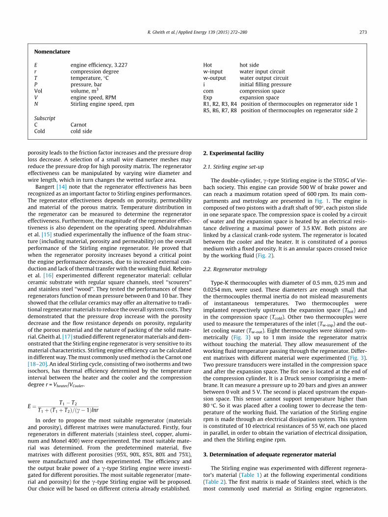
The double-cylinder, c-type Stirling engine is the ST05G of Vie-bach society. This engine can provide 500 W of brake power andcan reach a maximum rotation speed of 600 rpm. Its main com-partments and metrology are presented in Fig. 1. The engine iscomposed of two pistons with a draft shaft of 90�, each piston slidein one separate space. The compression space is cooled by a circuitof water and the expansion space is heated by an electrical resis-tance delivering a maximal power of 3.5 KW. Both pistons arelinked by a classical crank-rode system. The regenerator is locatedbetween the cooler and the heater. It is constituted of a porousmedium with a fixed porosity. It is an annular spaces crossed twiceby the working fluid (Fig. 2).
2.2. Regenerator metrology
Type-K thermocouples with diameter of 0.5 mm, 0.25 mm and0.0254 mm, were used. These diameters are enough small thatthe thermocouples thermal inertia do not mislead measurementsof instantaneous temperatures. Two thermocouples wereimplanted respectively upstream the expansion space (Thot) andin the compression space (Tcold). Other two thermocouples wereused to measure the temperatures of the inlet (Tw-inp) and the out-let cooling water (Tw-out). Eight thermocouples were skinned sym-metrically (Fig. 3) up to 1 mm inside the regenerator matrixwithout touching the material. They allow measurement of theworking fluid temperature passing through the regenerator. Differ-ent matrixes with different material were experimented (Fig. 3).Two pressure transducers were installed in the compression spaceand after the expansion space. The fist one is located at the end ofthe compression cylinder. It is a Druck sensor comprising a mem-brane. It can measure a pressure up to 20 bars and gives an answerbetween 0 volt and 5 V. The second is placed upstream the expan-sion space. This sensor cannot support temperature higher than80 �C. So it was placed after a cooling tower to decrease the tem-perature of the working fluid. The variation of the Stirling enginerpm is made through an electrical dissipation system. This systemis constituted of 10 electrical resistances of 55 W, each one placedin parallel, in order to obtain the variation of electrical dissipation,and then the Stirling engine rpm.
3. Determination of adequate regenerator material
The Stirling engine was experimented with different regenera-tor’s material (Table 1) at the following experimental conditions(Table 2). The first matrix is made of Stainless steel, which is themost commonly used material as Stirling engine regenerators.
TR5
TR6
TR7
TR8
TR1 TR2
TR3
TR4
Thot
Pexp.
Tw-inp.
Tw-out.
Pcomp.
Tcold
Water input
Heating system
Heater
Water output
Regenerator side 1 :
Series of 4 thermocouples
Regenerator side 2 :
Series of 4 thermocouples
Cooler
Fig. 1. Design of the c-type Stirling engine.
φ De
φ Di
A
A’ Coupe AA’
H
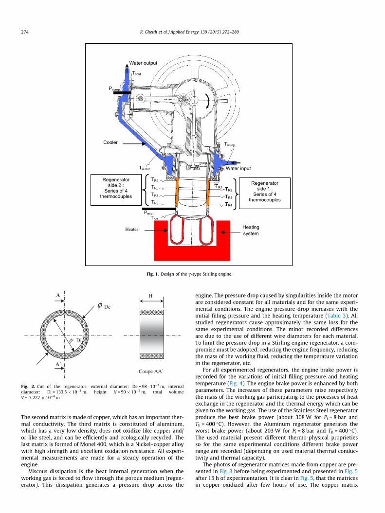
Fig. 2. Cut of the regenerator: external diameter: De = 98 � 10�3 m, internaldiameter: Di = 133.5 � 10�3 m, height H = 50 � 10�3 m, total volumeV = 3.227 � 10�4 m3.
274 R. Gheith et al. / Applied Energy 139 (2015) 272–280
The second matrix is made of copper, which has an important ther-mal conductivity. The third matrix is constituted of aluminum,which has a very low density, does not oxidize like copper and/or like steel, and can be efficiently and ecologically recycled. Thelast matrix is formed of Monel 400, which is a Nickel–copper alloywith high strength and excellent oxidation resistance. All experi-mental measurements are made for a steady operation of theengine.
Viscous dissipation is the heat internal generation when theworking gas is forced to flow through the porous medium (regen-erator). This dissipation generates a pressure drop across the
engine. The pressure drop caused by singularities inside the motorare considered constant for all materials and for the same experi-mental conditions. The engine pressure drop increases with theinitial filling pressure and the heating temperature (Table 3). Allstudied regenerators cause approximately the same loss for thesame experimental conditions. The minor recorded differencesare due to the use of different wire diameters for each material.To limit the pressure drop in a Stirling engine regenerator, a com-promise must be adopted: reducing the engine frequency, reducingthe mass of the working fluid, reducing the temperature variationin the regenerator, etc.
For all experimented regenerators, the engine brake power isrecorded for the variations of initial filling pressure and heatingtemperature (Fig. 4). The engine brake power is enhanced by bothparameters. The increases of these parameters raise respectivelythe mass of the working gas participating to the processes of heatexchange in the regenerator and the thermal energy which can begiven to the working gas. The use of the Stainless Steel regeneratorproduce the best brake power (about 308 W for Pi = 8 bar andTh = 400 �C). However, the Aluminum regenerator generates theworst brake power (about 203 W for Pi = 8 bar and Th = 400 �C).The used material present different thermo-physical proprietiesso for the same experimental conditions different brake powerrange are recorded (depending on used material thermal conduc-tivity and thermal capacity).
The photos of regenerator matrices made from copper are pre-sented in Fig. 3 before being experimented and presented in Fig. 5after 15 h of experimentation. It is clear in Fig. 5, that the matricesin copper oxidized after few hours of use. The copper matrix

Aluminum Stainless Steel
Copper Monel 400
4 skinned thermocouples
4 skinned thermocouples
Annular space : regenerator
a
b c
Fig. 3. Regenerator instrumentation and constituting material.
Table 1Characteristics of the tested porous structures.
Materials with porosity of 90%
Proprieties Stainless Steel304L
Copper Aluminum Monel400
Density (kg m�3) 7.850 8.920 2.700 8.800Thermal capacity
(J kg�1 K�1)477 385 902 430
Thermal conductivity(W m�1 K�1)
26 390 237 22
Table 2Experimental conditions.
Parameters Values
Heating temperature 300 �C, 400 �C and 500 �CInitial filling pressure 3 bar, 5 bar and 8 barCooling water flow rate 8.1 l/min
Table 3Pressures drop recorded for studied regenerators for different initial filling pressureand heating temperatures.
Pi = 3 bar Pi = 5 bar Pi = 8 bar
Th = 400 �CStainless Steel 0.1082 0.1234 0.132Copper 0.1093 0.1245 0.136Aluminum 0.1088 0.1236 0.1305Monel 400 0.1040 0.1236 0.1326
TH = 300 �C TH = 400 �C TH = 500 �C
Pi = 5 barStainless Steel 0.1101 0.1234 0.1423Copper 0. 1097 0.1245 0.1466Aluminum 0.1151 0.1236 0.1407Monel 400 0.1110 0.1236 0.1447
R. Gheith et al. / Applied Energy 139 (2015) 272–280 275
cannot be recommended to be used as a Stirling engine regenera-tor. In fact, heated at 500 �C, the copper oxidizes quickly (Fig. 5)because of the working fluid (air) contains about 21% of oxygen.This material oxidation changes quickly the physical characteris-tics of the copper, and then leads to heat exchanges deterioration.The aluminum matrix is formed by small diameter filaments. Theselater heated up to 500 �C melt to small masses causing inhomoge-neous porosity. The whole matrix is narrowed (Fig. 6).
The use of regenerator in Aluminum is limited by its meltingtemperature but it can be recommended for Stirling engine func-tioning at low heating temperature (>400 �C). After 15 h of exper-iments with a temperature below 500 �C the matrices of stainlesssteel and Monel 400 undergo no change in the geometry of themanufactured matrix. The stainless steel and the Monel 400 regen-erators, have good thermal efficiencies, respectively of 31% and25.5%. These two materials do not present a problem of oxidation.
Both materials present a good thermal capacity which allows tothe regenerator to absorbs/desorbs the maximal thermal energyfrom/to the working gas.
We proved the results found in Timoumi’s papers which specifythat a regenerator must have a high heat capacity and a low ther-mal conductivity. Decreasing the material thermal conductivityreduces conduction losses. Increasing material heat capacityincreases regenerator effectiveness.
Synthesis
Based on the results obtained in this section, the ‘‘stainlesssteel’’ can be considered as the best material used as Stirling engineregenerator. Although the thermo-physical properties of stainlesssteel accentuate the inhomogeneity of the heat transfer in eachsection of the regenerator, this material can still get the best per-formance for the c-type Stirling engine, and presents no risk of oxi-dation. Thus, the following test will be based on ‘‘Stainless Steel’’material with different porosities. To improve heat exchange ofthe regenerator and to reduce internal losses by conductivity, amaterial with high heat capacity and low thermal conductivitymust be chosen. The stainless steel and the Monel 400 verify bothstatements.
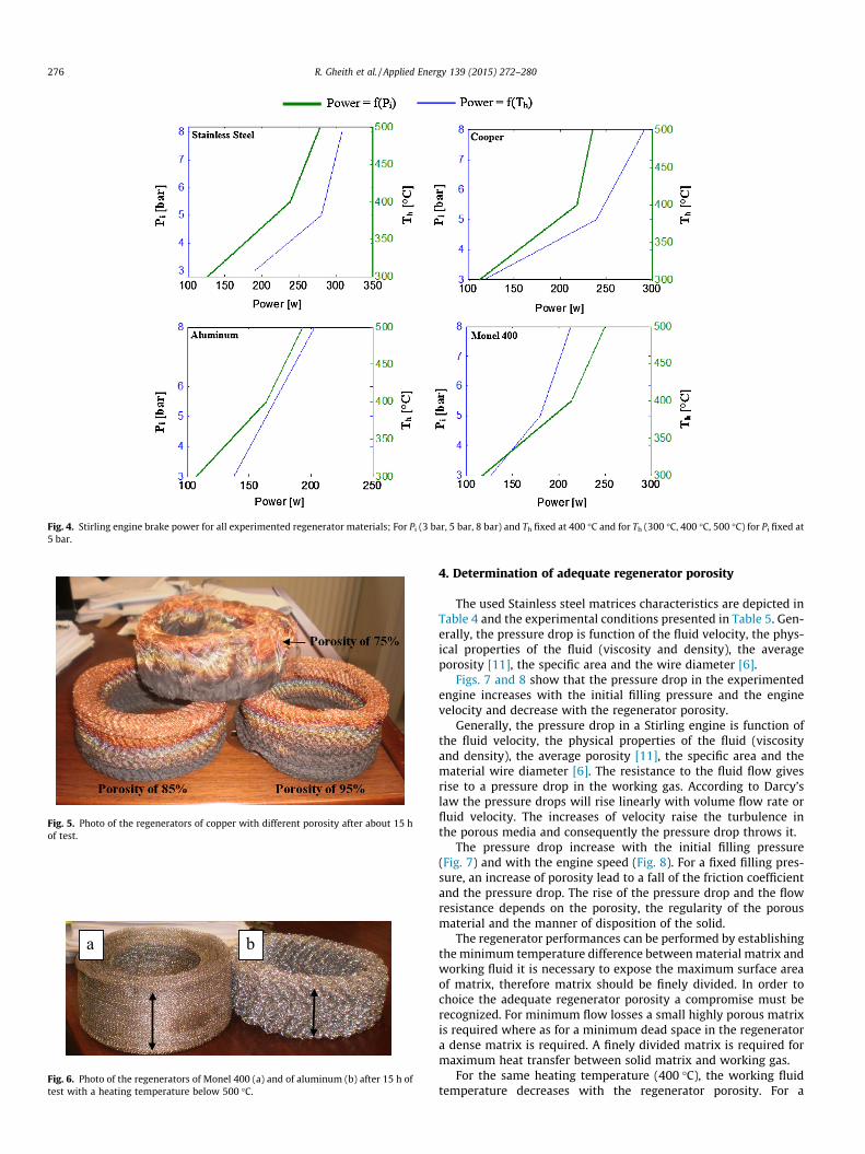
Fig. 4. Stirling engine brake power for all experimented regenerator materials; For Pi (3 bar, 5 bar, 8 bar) and Th fixed at 400 �C and for Th (300 �C, 400 �C, 500 �C) for Pi fixed at5 bar.
Fig. 5. Photo of the regenerators of copper with different porosity after about 15 hof test.
a b
Fig. 6. Photo of the regenerators of Monel 400 (a) and of aluminum (b) after 15 h oftest with a heating temperature below 500 �C.
276 R. Gheith et al. / Applied Energy 139 (2015) 272–280
4. Determination of adequate regenerator porosity
The used Stainless steel matrices characteristics are depicted inTable 4 and the experimental conditions presented in Table 5. Gen-erally, the pressure drop is function of the fluid velocity, the phys-ical properties of the fluid (viscosity and density), the averageporosity [11], the specific area and the wire diameter [6].
Figs. 7 and 8 show that the pressure drop in the experimentedengine increases with the initial filling pressure and the enginevelocity and decrease with the regenerator porosity.
Generally, the pressure drop in a Stirling engine is function ofthe fluid velocity, the physical properties of the fluid (viscosityand density), the average porosity [11], the specific area and thematerial wire diameter [6]. The resistance to the fluid flow givesrise to a pressure drop in the working gas. According to Darcy’slaw the pressure drops will rise linearly with volume flow rate orfluid velocity. The increases of velocity raise the turbulence inthe porous media and consequently the pressure drop throws it.
The pressure drop increase with the initial filling pressure(Fig. 7) and with the engine speed (Fig. 8). For a fixed filling pres-sure, an increase of porosity lead to a fall of the friction coefficientand the pressure drop. The rise of the pressure drop and the flowresistance depends on the porosity, the regularity of the porousmaterial and the manner of disposition of the solid.
The regenerator performances can be performed by establishingthe minimum temperature difference between material matrix andworking fluid it is necessary to expose the maximum surface areaof matrix, therefore matrix should be finely divided. In order tochoice the adequate regenerator porosity a compromise must berecognized. For minimum flow losses a small highly porous matrixis required where as for a minimum dead space in the regeneratora dense matrix is required. A finely divided matrix is required formaximum heat transfer between solid matrix and working gas.
For the same heating temperature (400 �C), the working fluidtemperature decreases with the regenerator porosity. For a

Table 4Five stainless steel matrixes with different porosities are manufactured.
Material: Stainless Steel
Porosity (%) Mass (kg) Wire diameter (m) Hydraulic diameter (m) Thermal conductivity (W m�1 K�1)
95 0.125 2.5e�4 0.95 1.3290 0.253 2.5e�4 0.90 2.6285 0.380 2.5e�4 0.85 3.9280 0.507 2.5e�4 0.80 5.2275 0.633 2.5e�4 0.75 6.52
Table 5Experimental conditions.
Parameters Values/designation
Heating temperature 300–500 �CInlet cooling temperature 12 �CInitial filling pressure 3–8 barCooling water flow rate 8.16 l/minMaterial constituting material Stainless steelRegenerator porosities 95%, 90%, 85%, 80%, 75%
75 80 85 90 950.095
0.1
0.105
0.11
0.115
0.12
0.125
0.13
Matrices porosities [%]
Pre
ssur
e dr
op [b
ar]
Pi = 3 bar
Pi = 5 bar
Pi = 8 bar
Fig. 7. The pressure drop vs. the matrices porosity for different charge pressure.
75 80 85 90 950.106
0.108
0.11
0.112
0.114
0.116
0.118
0.12
Pre
ssur
e dr
op [b
ar]
V = 370 rpmV = 340 rpmV = 320 rpmV = 300 rpm
Matrix porosities [%]
Fig. 8. The pressure drop vs. the matrices porosities for different engine speed (V).
75 80 85 90 95160
180
200
220
240
260
280
Tem
pera
ture
TR
4 [°
C]
Pi = 3 bar
Pi = 5 bar
Pi = 8 bar
Matrix porosities [%]
Fig. 9. Working fluid temperature crossing the regenerator for different stainlesssteel porosities (temperature recorded by thermocouples TR1) for Pi = 3, 5 or 8 barand Th = 400 �C).
R. Gheith et al. / Applied Energy 139 (2015) 272–280 277
porosity of 75% the regenerator temperature is about 268 �C,270 �C and 278 �C for an initial filling pressure of respectively
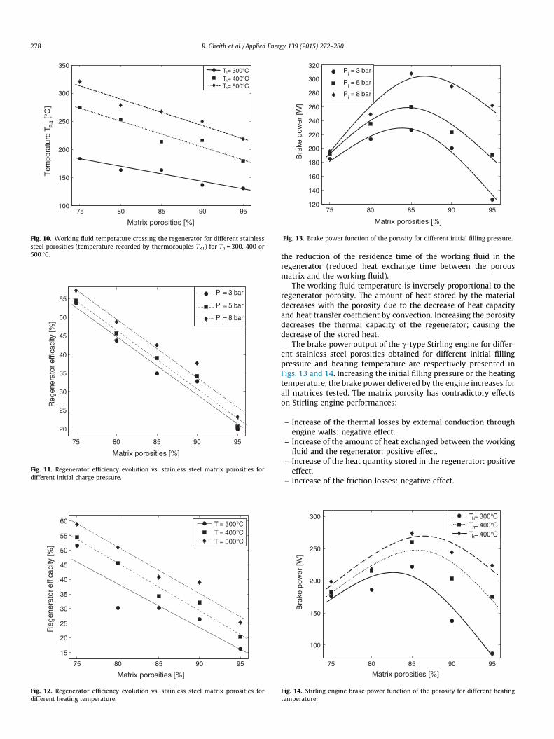
3 bar, 5 bar and 8 bar. The pressure has no significant influenceon the temperature variation in a Stirling engine regenerator(Fig. 9). Indeed, increasing the initial filling pressure led to phe-nomena with contradictory effects on the performance of the Stir-ling engine. It increases the mass of the working fluid passingthrough the regenerator and increases the engine rpm. The firstphenomenon enhance the quantity of heat exchanged betweenthe regenerator and the working fluid and the second phenomenondecrease the exchanging duration between the working fluid andthe regenerator material. The heating temperature increase causesthe increase of the working fluid temperature (Fig. 10).
The Stirling engine regenerator is evaluated from its efficiencywhich is defined as the ratio of the amount of heat effectivelytransferred during an engine cycle by the maximum amount ofheat transferred during the same cycle. The regenerator is consid-ered ideal if its efficiency is about 1. This parameter dependsmainly on the regenerator porosity, the regenerator temperaturevariation and the regenerator volume. The regenerator efficiencydecreases with the porosity and increase with the charge pressureand with the heating temperature (Figs. 11 and 12).
Increasing the porosity of the regenerator causes an increase ofthe pore volume and the decrease in contact area between thematerial and the inner walls of the Stirling engine. This effectreduces the residence time of the fluid working in the regenerator,and therefore losses due to the internal and external conduction.For the same heating temperature (400 �C), we find that the tem-perature of the working fluid decreases as the porosity of theregenerator.
The pressure variations have a slight influence on the change ofworking gas temperature crossing the regenerator. The increase ofinitial charge pressure causes simultaneously: the increase of themass of the working fluid passing through the regenerator andthe flow velocity. The rise in the speed of the Stirling engine causes
75 80 85 90 95100
150
200
250
300
350
Tem
pera
ture
TR
4 [°C
]
T = 300°CT = 400°CT = 500°C
Matrix porosities [%]
h
h
h
Fig. 10. Working fluid temperature crossing the regenerator for different stainlesssteel porosities (temperature recorded by thermocouples TR1) for Th = 300, 400 or500 �C.
75 80 85 90 95
20
25
30
35
40
45
50
55
Reg
ener
ator
effi
caci
ty [%
]
Pi = 3 bar
Pi = 5 bar
Pi = 8 bar
Matrix porosities [%]
Fig. 11. Regenerator efficiency evolution vs. stainless steel matrix porosities fordifferent initial charge pressure.
75 80 85 90 95
15
20
25
30
35
40
45
50
55
60
Reg
ener
ator
effi
caci
ty [%
]
T = 300°CT = 400°CT = 500°C
Matrix porosities [%]
Fig. 12. Regenerator efficiency evolution vs. stainless steel matrix porosities fordifferent heating temperature.
75 80 85 90 95120
140
160
180
200
220
240
260
280
300
320
Bra
ke p
ower
[W]
Pi = 3 bar
Pi = 5 bar
Pi = 8 bar
Matrix porosities [%]
Fig. 13. Brake power function of the porosity for different initial filling pressure.
278 R. Gheith et al. / Applied Energy 139 (2015) 272–280
the reduction of the residence time of the working fluid in theregenerator (reduced heat exchange time between the porousmatrix and the working fluid).
The working fluid temperature is inversely proportional to theregenerator porosity. The amount of heat stored by the materialdecreases with the porosity due to the decrease of heat capacityand heat transfer coefficient by convection. Increasing the porositydecreases the thermal capacity of the regenerator; causing thedecrease of the stored heat.
The brake power output of the c-type Stirling engine for differ-ent stainless steel porosities obtained for different initial fillingpressure and heating temperature are respectively presented inFigs. 13 and 14. Increasing the initial filling pressure or the heatingtemperature, the brake power delivered by the engine increases forall matrices tested. The matrix porosity has contradictory effectson Stirling engine performances:
– Increase of the thermal losses by external conduction throughengine walls: negative effect.
– Increase of the amount of heat exchanged between the workingfluid and the regenerator: positive effect.
– Increase of the heat quantity stored in the regenerator: positiveeffect.
– Increase of the friction losses: negative effect.
75 80 85 90 95
100
150
200
250
300
Bra
ke p
ower
[W]
T = 300°CT = 400°CT = 400°C
h
h
h
Matrix porosities [%]
Fig. 14. Stirling engine brake power function of the porosity for different heatingtemperature.
300 310 320 330 340 350 360 370180
190
200
210
220
230
240
95%90%85%80%75%
rpm [rpm]
Bra
ke p
ower
[W]
Fig. 15. Brake power evolution vs. regenerator porosity and engine RPM.
74 76 78 80 82 84 86 88 90 92 94 9620.3
20.35
20.4
20.45
Matrix porosities [%]E
C [%
]
Th=300°C
74 76 78 80 82 84 86 88 90 92 94 9623.85
23.9
23.95
24
Matrix porosities [%]
EC
[%]
Th=400°C
74 76 78 80 82 84 86 88 90 92 94 9625.9
26
26.1
Matrix porosities [%]
EC
[%]
Th=500°C
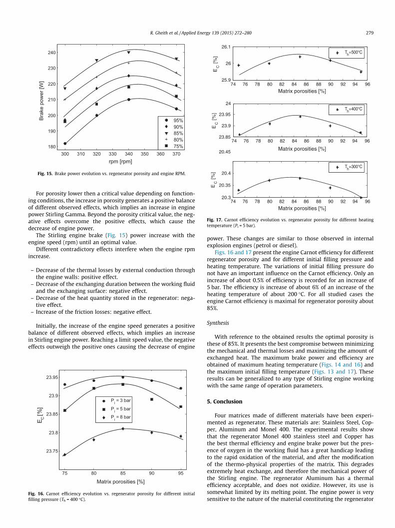
Fig. 17. Carnot efficiency evolution vs. regenerator porosity for different heatingtemperature (Pi = 5 bar).
R. Gheith et al. / Applied Energy 139 (2015) 272–280 279
For porosity lower then a critical value depending on function-ing conditions, the increase in porosity generates a positive balanceof different observed effects, which implies an increase in enginepower Stirling Gamma. Beyond the porosity critical value, the neg-ative effects overcome the positive effects, which cause thedecrease of engine power.
The Stirling engine brake (Fig. 15) power increase with theengine speed (rpm) until an optimal value.
Different contradictory effects interfere when the engine rpmincrease.
– Decrease of the thermal losses by external conduction throughthe engine walls: positive effect.
– Decrease of the exchanging duration between the working fluidand the exchanging surface: negative effect.
– Decrease of the heat quantity stored in the regenerator: nega-tive effect.
– Increase of the friction losses: negative effect.
Initially, the increase of the engine speed generates a positivebalance of different observed effects, which implies an increasein Stirling engine power. Reaching a limit speed value, the negativeeffects outweigh the positive ones causing the decrease of engine
75 80 85 90 95
23.75
23.8
23.85
23.9
23.95
Pi = 3 bar
Pi = 5 bar
Pi = 8 bar
Matrix porosities [%]
E C [%
]
Fig. 16. Carnot efficiency evolution vs. regenerator porosity for different initialfilling pressure (Th = 400 �C).
power. These changes are similar to those observed in internalexplosion engines (petrol or diesel).
Figs. 16 and 17 present the engine Carnot efficiency for differentregenerator porosity and for different initial filling pressure andheating temperature. The variations of initial filling pressure donot have an important influence on the Carnot efficiency. Only anincrease of about 0.5% of efficiency is recorded for an increase of5 bar. The efficiency is increase of about 6% of an increase of theheating temperature of about 200 �C. For all studied cases theengine Carnot efficiency is maximal for regenerator porosity about85%.
Synthesis
With reference to the obtained results the optimal porosity isthese of 85%. It presents the best compromise between minimizingthe mechanical and thermal losses and maximizing the amount ofexchanged heat. The maximum brake power and efficiency areobtained of maximum heating temperature (Figs. 14 and 16) andthe maximum initial filling temperature (Figs. 13 and 17). Theseresults can be generalized to any type of Stirling engine workingwith the same range of operation parameters.
5. Conclusion
Four matrices made of different materials have been experi-mented as regenerator. These materials are: Stainless Steel, Cop-per, Aluminum and Monel 400. The experimental results showthat the regenerator Monel 400 stainless steel and Copper hasthe best thermal efficiency and engine brake power but the pres-ence of oxygen in the working fluid has a great handicap leadingto the rapid oxidation of the material, and after the modificationof the thermo-physical properties of the matrix. This degradesextremely heat exchange, and therefore the mechanical power ofthe Stirling engine. The regenerator Aluminum has a thermalefficiency acceptable, and does not oxidize. However, its use issomewhat limited by its melting point. The engine power is verysensitive to the nature of the material constituting the regenerator

280 R. Gheith et al. / Applied Energy 139 (2015) 272–280
and the Stainless Steel is the best material that can be used asStirling engine regenerator working in this rage of heatingtemperature. Based on various experiments, it can be concludedthat the matrix Stainless Steel is best placed to constitute theGamma Stirling engine regenerator. The experimentation of differ-ent stainless porosities, shows that a porosity of 85% presents themaximal brake power and engine efficiency.
A maximal heating temperature (500 �C) and maximal initialfilling pressure (8 bar) applied to a stainless steel regenerator ofa porosity of 85% offer the optimal Stirling engine performances(brake power of 320 W and a Carnot efficiency over 26%).
Acknowledgements
This work was supported by the laboratories LAMIH CNRSUMR 8201 (University of Valenciennes et du Hainaut-Cambresis,France) and LESTE (ENIM, University of Monastir, Tunisia). Thesesupports are gratefully acknowledged.
References
[1] Andersen SK, Carlsen H, Thomsen PG. Numerical study on optimal Stirlingengine regenerator matrix design taking into account the effects of matrixtemperature oscillations. Energy Convers Manage 2006;47:894–908.
[2] Organ AJ. Thermodynamics and gas dynamics of the Stirling cyclemachine. Cambridge University Press; 1992.
[3] Bangert K. Production of optimised metal foams for Stirling engineregenerators. Mini project Report. The University of Sheffield; 2010.
[4] Frigerio S, Mehl M, Ranzi E, Schweiger D, Schedler J. Improve efficiency ofthermal regenerators and VOCs abatement systems: an experimental andmodeling study. Exp Therm Fluid Sci 2007;31:403–41.
[5] Waele ATAM. Finite heat-capacity effects in regenerators. Cryogenics2012;52:1–7.
[6] Chang WS. Porosity and effective thermal conductivity of wire screens. ASME, JHeat Transfer 1990;112:5–9.
[7] Park SH, Lee YS. An approximate thermal analysis of Stirling engineregenerators. KSME J 1993;7(2):133–43.
[8] (a) Tlili I, Timoumi Y, Ben Nasrallah S. Thermodynamic analysis of the Stirlingheat engine with regenerative losses and internal irreversibilities. Int J Eng Res2008;9:45. http://dx.doi.org/10.1243/14680874JER01707;(b) Tlili (b) I, Timoumi Y, Ben Nasrallah S. Analyse and design consideration ofmean temperature differential Stirling engine for solar application. RenewEnergy 2008;33:1911–21.
[9] Dallaire J, Gosselin L, da Silva AK. Conceptual optimization of a rotary heatexchanger with a porous core. Int J Therm Sci 2010;49:454–62.
[10] Martins LS, Ordonez JC, Vargas JVC, Parise JAR. Thermodynamic optimizationof a regenerator heat exchanger. Appl Therm Eng 2012;45–46:42–51.
[11] Chen WL, Wong KL, Po LW. A numerical analysis on the performance of apressurized twin power piston gamma-type Stirling engine. Energy ConversManage 2012;62:84–92.
[12] Timoumi Y, Tlili I, Ben Nasrallah S. Analysis and design consideration of meantemperature differential Stirling engine for solar application. Renew Energy2008;33:1911–21.
[13] Cheng CH, Yang HS. Optimization of geometrical parameters for Stirlingengines based on theoretical analysis. Appl Energy 2012;92:395–405.
[14] Bangert K. Production of optimised metal foams for Stirling engineregenerators. Mini project Report. University of Sheffield; 2010.
[15] Abdulrahman SA, Zhibin Y, Jaworski AJ. Selection and experimental evaluationof low-cost porous materials for regenerator applications in thermoacousticengines. Mater Des 2011;32:217–28.
[16] Ribeiro AM, Neto P, Pinho C. Mean porosity and pressure drop measurement inpacked beds of monosized spheres: side wall effects. Int Rev Chem Eng2010;2(1):40–6.
[17] Gheith R, Aloui F, Ben Nasrallah S. Study of the regenerator constitutingmaterial influence on a gamma type Stirling engine. J Mech Sci Technol2012;26(4):1251–5.
[18] Rider GT, Huper C. Stirling engines. London–New York: E. and F.N. Spon; 1983.[19] Urielli I, Berchowitz DM. Stirling cycle engine analysis. Bristol: Taylor & Francis
Group; 1984.[20] Organ A. The regenerator and the Stirling engine. New York: John Wiley &
Sons; 1997.
Related Documents