Geopolymers based on spent catalyst residue from a fluid catalytic cracking (FCC) process Erich D. Rodríguez a,b,⇑ , Susan A. Bernal b,c , John L. Provis b,c , John D. Gehman d , José M. Monzó a , Jordi Payá a , M. Victoria Borrachero a a Instituto de Ciencia y Tecnología del Hormigón (ICITECH), Universitat Politècnica de València, Valencia 46022, Spain b Department of Chemical and Biomolecular Engineering, University of Melbourne, Victoria 3010, Australia c Department of Materials Science and Engineering, University of Sheffield, Sheffield S1 3JD, United Kingdom d School of Chemistry and Bio21 Institute, University of Melbourne, Victoria 3010, Australia highlights " Valorization of a residue as a precursor for the production of geopolymers. " First detailed study of a spent FCC catalyst to produce geopolymers. " Understanding for the structural features in the spent FCC catalyst-based geopolymer. article info Article history: Received 21 July 2012 Received in revised form 19 February 2013 Accepted 19 February 2013 Available online 16 March 2013 Keywords: Geopolymer Fluid catalytic cracking Catalyst residue Zeolites abstract This paper assesses the use of alkali activation technology in the valorization of a spent fluid catalytic cracking (FCC) catalyst, which is a residue derived from the oil-cracking process, to produce ‘geopolymer’ binders. In particular, the effects of activation conditions on the structural characteristics of the spent cat- alyst-based geopolymers are determined. The zeolitic phases present in the spent catalyst are the main phases participating in the geopolymerization reaction, which is driven by the conversion of the zeolitic material to a highly Al-substituted aluminosilicate binder gel. Higher alkali content and SiO 2 /Na 2 O ratio lead to a denser structure with a higher degree of geopolymer gel formation and increased degree of crosslinking, as identified through 29 Si MAS NMR. These results highlight the feasibility of using spent FCC catalyst as a precursor for geopolymer production. Crown Copyright Ó 2013 Published by Elsevier Ltd. All rights reserved. 1. Introduction Catalysis is a widely used process in the petrochemical industry for the transformation of crude oil to gasoline and other fuel prod- ucts, with an economic impact estimated at more than 6.3 million barrels per day in 2012 in the US alone [1]. A wide range of zeolites and molecular sieves are commonly used in the fluid catalytic cracking (FCC) process, but the catalysts are degraded when in use. Partial or complete regeneration of spent FCC catalyst can be carried out in some cases, although in the longer term its continual reuse is not possible due to irreversible deactivation and structural damage to the zeolitic material. More than 400 petroleum refiner- ies worldwide refine crude oil via fluid cracking catalytic units [2], and 160,000 tons of spent catalyst residue are produced every year by the petrochemical industry. However, with an anticipated 5% annual increase in catalyst consumption, the spent catalyst res- idue may exceed 200,000 tons annually within a few years [3]. This residue mainly consists of SiO 2 and Al 2 O 3 , and can be considered as an agglomeration of zeolite crystals (mainly zeolite Y in the case of the material studied here) held together by an aluminosilicate matrix. During the cracking reactions, the surface of FCC catalyst parti- cles can be contaminated with different cations (including Ni, V, Fe, Cu and/or Na), and coke (carbon) is deposited in ppm levels or more. According to the European waste catalog (commission 94/ 3EEC), spent FCC catalyst (code 160804) is classified as a non-haz- ardous material and has been used in landfill, as a source of SiO 2 and Al 2 O 3 in the Portland cement clinkerization process [4], as a fil- ler in asphaltic concretes [5], as a substitute for kaolin in the cera- mic industry [6], as a raw material in the synthesis of some zeolites or for extraction of active Al 2 O 3 [7,8], in the production of bricks through sintering processes [9], in the refractory industry [10] 0016-2361/$ - see front matter Crown Copyright Ó 2013 Published by Elsevier Ltd. All rights reserved. http://dx.doi.org/10.1016/j.fuel.2013.02.053 ⇑ Corresponding author. E-mail addresses: [email protected], [email protected] (E.D. Rodríguez). Fuel 109 (2013) 493–502 Contents lists available at SciVerse ScienceDirect Fuel journal homepage: www.elsevier.com/locate/fuel

1-s2.0-S0016236113001555-main.pdf
Dec 14, 2015
Welcome message from author
This document is posted to help you gain knowledge. Please leave a comment to let me know what you think about it! Share it to your friends and learn new things together.
Transcript

Fuel 109 (2013) 493–502
Contents lists available at SciVerse ScienceDirect
Fuel
journal homepage: www.elsevier .com/locate / fuel
Geopolymers based on spent catalyst residue from a fluid catalytic
cracking (FCC) process0016-2361/$ - see front matter Crown Copyright � 2013 Published by Elsevier Ltd. All rights reserved.http://dx.doi.org/10.1016/j.fuel.2013.02.053
⇑ Corresponding author.E-mail addresses: [email protected], [email protected]
(E.D. Rodríguez).
Erich D. Rodríguez a,b,⇑, Susan A. Bernal b,c, John L. Provis b,c, John D. Gehman d, José M. Monzó a,Jordi Payá a, M. Victoria Borrachero a
a Instituto de Ciencia y Tecnología del Hormigón (ICITECH), Universitat Politècnica de València, Valencia 46022, Spainb Department of Chemical and Biomolecular Engineering, University of Melbourne, Victoria 3010, Australiac Department of Materials Science and Engineering, University of Sheffield, Sheffield S1 3JD, United Kingdomd School of Chemistry and Bio21 Institute, University of Melbourne, Victoria 3010, Australia
h i g h l i g h t s
" Valorization of a residue as a precursor for the production of geopolymers." First detailed study of a spent FCC catalyst to produce geopolymers." Understanding for the structural features in the spent FCC catalyst-based geopolymer.
a r t i c l e i n f o
Article history:Received 21 July 2012Received in revised form 19 February 2013Accepted 19 February 2013Available online 16 March 2013
Keywords:GeopolymerFluid catalytic crackingCatalyst residueZeolites
a b s t r a c t
This paper assesses the use of alkali activation technology in the valorization of a spent fluid catalyticcracking (FCC) catalyst, which is a residue derived from the oil-cracking process, to produce ‘geopolymer’binders. In particular, the effects of activation conditions on the structural characteristics of the spent cat-alyst-based geopolymers are determined. The zeolitic phases present in the spent catalyst are the mainphases participating in the geopolymerization reaction, which is driven by the conversion of the zeoliticmaterial to a highly Al-substituted aluminosilicate binder gel. Higher alkali content and SiO2/Na2O ratiolead to a denser structure with a higher degree of geopolymer gel formation and increased degree ofcrosslinking, as identified through 29Si MAS NMR. These results highlight the feasibility of using spentFCC catalyst as a precursor for geopolymer production.
Crown Copyright � 2013 Published by Elsevier Ltd. All rights reserved.
1. Introduction
Catalysis is a widely used process in the petrochemical industryfor the transformation of crude oil to gasoline and other fuel prod-ucts, with an economic impact estimated at more than 6.3 millionbarrels per day in 2012 in the US alone [1]. A wide range of zeolitesand molecular sieves are commonly used in the fluid catalyticcracking (FCC) process, but the catalysts are degraded when inuse. Partial or complete regeneration of spent FCC catalyst can becarried out in some cases, although in the longer term its continualreuse is not possible due to irreversible deactivation and structuraldamage to the zeolitic material. More than 400 petroleum refiner-ies worldwide refine crude oil via fluid cracking catalytic units [2],and �160,000 tons of spent catalyst residue are produced every
year by the petrochemical industry. However, with an anticipated5% annual increase in catalyst consumption, the spent catalyst res-idue may exceed 200,000 tons annually within a few years [3]. Thisresidue mainly consists of SiO2 and Al2O3, and can be considered asan agglomeration of zeolite crystals (mainly zeolite Y in the case ofthe material studied here) held together by an aluminosilicatematrix.
During the cracking reactions, the surface of FCC catalyst parti-cles can be contaminated with different cations (including Ni, V, Fe,Cu and/or Na), and coke (carbon) is deposited in ppm levels ormore. According to the European waste catalog (commission 94/3EEC), spent FCC catalyst (code 160804) is classified as a non-haz-ardous material and has been used in landfill, as a source of SiO2
and Al2O3 in the Portland cement clinkerization process [4], as a fil-ler in asphaltic concretes [5], as a substitute for kaolin in the cera-mic industry [6], as a raw material in the synthesis of some zeolitesor for extraction of active Al2O3 [7,8], in the production of bricksthrough sintering processes [9], in the refractory industry [10]

494 E.D. Rodríguez et al. / Fuel 109 (2013) 493–502
and as a supplementary cementitious material (SCM) in blendedcement production [11–15].
The inclusion of spent FCC catalyst as an SCM in Portland ce-ment blends can lead to an increase in the mechanical strengthand the improvement of some durability properties as a conse-quence of its high reactivity with Ca(OH)2 [12,13]. The zeoliticstructures in spent FCC catalyst have the ability to promote the for-mation of an Al-substituted C–S–H type gel (via the pozzolanicreaction) and/or hydrated aluminate phases [16]. The presence ofsome contaminants, such as Ni, can reduce the pozzolanic reactiv-ity of the spent catalyst, and so the potential use of spent FCC cat-alysts in the production of Portland cement-based buildingmaterials must be very carefully assessed [14,17]. It has been re-ported that mechanical [18], thermal [19], and chemical treat-ments [20] can enhance the effectiveness of spent FCC catalyst asan SCM in ordinary Portland cement systems.
Geopolymers are materials with properties similar to those ofhardened Portland cement, produced through the alkali activationof an aluminosilicate precursor [21,22]. The geopolymer structureis dominated by an aluminosilicate type gel, comparable with anamorphous zeolite structure [23]. The interest in geopolymers asa potential alternative to Portland cement has increased consider-ably during the last two decades, as these materials can presenttechnical, environmental and economic advantages when com-pared with conventional cements. Geopolymer production is asso-ciated with lower energy consumption and lower CO2 emissionscompared with the Portland cement industry, as well as the benefitof providing a pathway to the valorization of high-volume reactivealuminosilicate industrial wastes or by-products [22].
Depending on the raw materials selected and their processingconditions, geopolymers can exhibit high compressive strengths,moderate shrinkage, and good performance when exposed toaggressive environments such as strong acids and high tempera-tures [23]. Industrial by-products such as fly ash from coal com-bustion, metallurgical slags, natural minerals including calcinedclays, and volcanic ashes, have been successfully used as alumino-silicate precursors in the production of geopolymer systems [24].However, the availability of those precursors in some parts of theworld is limited, and therefore, there is an increasing need to iden-tify different precursors with similar chemical and structural prop-erties that can be widely available. Considering that spent FCCcatalyst is a reactive aluminosilicate material which is producedin relatively high volumes and which does not currently have a di-rect pathway to valorization, it is likely that this material is a fea-sible precursor for the larger-scale synthesis of geopolymers; it hasrecently been demonstrated [25], that alkali-activation might be adesirable alternative for the valorization of this by-product.
Fig. 1. Scanning electron micrographs of (A) untreated
The aim of the present study is to analyze in more detail the po-tential application of alkali-activation of spent FCC catalyst wasteto produce alternative binders, through the development of a bet-ter understanding of the structural features of a new spent FCC cat-alyst-based geopolymer. The effect of the alkali and silicate contentin the structure of spent FCC catalyst-based geopolymers is deter-mined using X-ray diffraction (XRD), Fourier transform infraredspectroscopy (FTIR), solid state nuclear magnetic resonance spec-troscopy (NMR), and scanning electron microscopy (SEM).
2. Experimental program
2.1. Materials
Spent fluid catalytic cracking catalyst was supplied by BP OilEspaña (Castellon, Spain), and prior to activation was subjectedto a mechanical treatment using a ball mill (Mill-2 Gabrielli) for20 min to increase its reactivity [12,26]. Fig. 1 shows the destruc-tion of the spent fluid catalytic cracking catalyst particles as a con-sequence of the mechanical treatment applied. The particle sizerange determined by laser granulometry was 0.8–100 lm with amean particle diameter of 17.1 lm. According to the chemicalcomposition (Table 1), the spent FCC catalyst has a SiO2/Al2O3 ratioclose to unity. The total silica content determined in previous stud-ies following the procedure suggested by Payá et al. [27] was 48.3%,while the reactive silica content determined by a KOH (4 M) attackwas 41.3%.
The catalyst residue contains different crystalline zeolitephases, which are identifiable through XRD (Fig. 2), with the useof the Powder Diffraction File (PDF) and American MineralogistCrystal Structure Database (AMCSD) reference resources. The fauj-asite-type structure of dehydrated dealuminated US-Y zeolite(|Al5.6O22.4|�[Si175.7Al16.3O384], PDF # 00-045-0112), ZSM-5 zeolite(MnAlnSi(96�n)O192�16H2O; n < 27; PDF # 00-044-0002) and morde-nite ((Ca,Na2,K2)Al2Si10O24�7H2O; AMCSD # 0003444) were ob-served. Different high-temperature aluminosilicate polymorphssuch as sillimanite (Al2SiO5; PDF # 00-038-0471), kyanite (Al2SiO5;PDF # 00-011-0046), and mullite (3Al2O3�2SiO2; PDF # 00-015-0776), as well as quartz (SiO2, PDF# 00-046-1045), were also iden-tified. Sillimanite and kyanite are used as active fillers in catalystsin the petroleum industry [28]; non-catalytic or non-reactive alu-mina–silica compounds are used in the catalyst to remove carbo-naceous and metallic contaminants (Ni or V) [29]. The spent FCCcatalyst also has a high content of amorphous (glassy) aluminosil-icate phases as a consequence of the partial destruction of the zeo-lite structures by the inclusion of lanthanum and titanium duringcatalyst synthesis [30], and also in service. Lanthanum oxide
spent FCC catalyst and (B) ball-milled FCC catalyst.

Table 1Chemical composition of the spent fluid catalytic crack-ing catalyst used, on an oxide basis, from X-ray fluores-cence analysis. LOI is loss on ignition.
Compound Wt.%
SiO2 46.94Al2O3 48.40Fe2O3 0.59CaO 0.11MgO 0.17SO3 0.02K2O 0.02Na2O 0.31TiO2 1.20P2O5 0.01Nd2O3 0.04V2O5 0.01La2O3 1.36CeO2 0.12Pr2O3 0.19LOI (950 �C) 0.50
Table 2Mix designs of geopolymer samples.
Geopolymer Alkali content (wt.%Na2O)
SiO2/Na2O molar ratio in alkaliactivator
7N0 7 07N1 7 1.07N2 7 2.010N0 10 010N1 10 1.010N2 10 2.015N0 15 015N1 15 1.015N2 15 2.0
E.D. Rodríguez et al. / Fuel 109 (2013) 493–502 495
(La2O3, PDF #00-022-0641) and some traces of aluminum titaniumsilicate (Al4Ti2SiO12; PDF # 00-022-0502) and anatase (TiO2, PDF #00-021-1272) were also identified.
As alkali activators, sodium silicate solutions were used, synthe-sized by blending distilled water, analytical grade sodium hydrox-ide pellets (NaOH; Sigma–Aldrich, Australia) and a commercialsodium silicate solution (PQ Silicates, Australia) with 28.7 wt.%SiO2, 8.9 wt.% Na2O and 62.4 wt.% H2O. The proportions of water,NaOH and sodium silicate were adjusted to produce alkali activa-tors with compositions Na2O�rSiO2�11H2O, where r = 0, 1.0, and 2.0.
2.2. Sample preparation
The spent FCC catalyst was activated with activator doses of7 wt.%, 10 wt.% and 15 wt.% of Na2O, relative to the mass of spentcatalyst residue, and a water/catalyst residue ratio of 0.50. Themix designs are given in Table 2.
2 theta (de
Fig. 2. X-ray diffractograms of the unreacted spent FCC cata
The pastes were mixed for three minutes and then poured into aplastic container and sealed for curing at 40 �C for 28 days. Sampleswere milled, washed with acetone to halt the reaction process, andstored sealed until characterization.
2.3. Tests conducted
The reaction products, and structures of the geopolymers pro-duced, were assessed through:
– X-ray diffraction (XRD) using a Bruker D8 Advance instrumentwith Ni-filtered Cu Ka radiation, with a step size of 0.020�and 4 s/step.
– Fourier transform infrared (FTIR) spectroscopy via the KBr pellettechnique, using a Bruker Tensor 27 spectrometer and 32 scansper spectrum. Spectra were collected in transmittance modefrom 4000 to 400 cm�1 at a resolution of 4 cm�1.
– Solid-state 29Si and 27Al magic angle spinning nuclear magneticresonance (MAS NMR) spectra were obtained on a Varian DirectDrive VNMRS-600 spectrometer (14.1 T) using a MAS NMRprobe for 4 mm o.d. zirconia rotors and a spinning speed ofmR = 10.0 kHz. 29Si MAS NMR experiments were acquired usinga pulse width of 4 ls and a relaxation delay of 20 s, and3664–4096 scans. 27Al MAS NMR experiments were conducted
grees)
lyst and geopolymers produced after 28 days of curing.

496 E.D. Rodríguez et al. / Fuel 109 (2013) 493–502
at 156.3 MHz on the same instrument, with a pulse width of0.5 ls, a relaxation delay of 2 s, and 1024 scans. 29Si and 27Alchemical shifts are referenced to external samples of tetrameth-ylsilane (TMS) and a 1.0 M aqueous solution of Al(NO3)3�9H2O,respectively.
– Scanning electron microscopy (SEM) was conducted using a FEIQuanta microscope (ESEM) with 15 kV accelerating voltage. Thesamples were evaluated in low vacuum mode to enable theanalysis of uncoated fracture surfaces.
3. Results and discussion
3.1. X-ray diffraction (XRD)
The alkali-activation of the catalyst residue leads to the dissolu-tion of the faujasite type zeolite (identified by XRD, as dehydrated,dealuminated zeolite Y), as shown in Fig. 2 by the disappearance ofthe peaks assigned to this phase in the geopolymer samples. Ahigher alkalinity (lower SiO2/Na2O ratios) leads also to the dissolu-tion of mordenite, whose peaks decrease with increasing alkalicontent. This behavior is also observed with higher SiO2/Na2O ra-tios in the silicate-activated systems.
Some of the crystalline aluminosilicate phases identified in theunreacted spent FCC catalyst (Fig. 2), such as mullite, kyanite andsillimanite, along with quartz, are observed in the geopolymersamples regardless of the activation conditions used. This is consis-tent with the known behavior of mullite and quartz in fly ash-based geopolymers, where these crystalline phases are seen to beunreactive [31]. However, the intensities of the peaks assigned tokyanite do decrease when the catalyst residue is activated with15% Na2O, especially when the SiO2/Na2O ratio is also high (sample15N2).
The higher deviation of the XRD data from the baseline at in-creased alkali content is attributed to the formation of a highlyamorphous new gel, consistent with the well-known geopolymergel [32]. The degree of amorphicity of this gel is controlled bythe degree of polycondensation and/or the SiO2/Na2O ratio [33].The higher amorphicity identified in the silicate-activated systemswith high alkalinity (such as 15N1 and 15N2) can contribute toenhancement of the mechanical performance according to the re-sults previously obtained by Tashima et al. [25]. In that study, itwas identified when producing FCC catalyst-based geopolymersthat increasing the hydroxide concentration and the inclusion ofsoluble silica in the alkali activator promotes increased compres-sive strength, reaching values of up to 68 MPa after 3 days of curingat 65 �C.
The absence of the diffraction peaks corresponding to the US-Yzeolite and the reduction of the mordenite peaks in the geopoly-mer samples, when compared with the unreacted catalyst residue(Fig. 2), indicate that these phases are participating in the geopoly-merization reactions. To explain why some zeolites in the spentFCC residue are more reactive upon alkaline activation than others,it is important to consider the changes that the zeolites of the cat-alyst suffer during the catalytic cracking. The dehydrated dealumi-nated US-Y zeolite identified in the spent FCC catalyst residue isone of the most important zeolites used in catalytic cracking pro-cesses, and it is the major active component of the catalyst parti-cles used in the hydrocarbon cracking reaction. During cokeremoval, the catalyst particles are calcined under extreme hydro-thermal conditions and a considerable structural change occursin the Brønsted acid sites. Therefore, framework destruction anda dealuminated structure can be identified, promoting the forma-tion of a higher number of acid sites. The presence of these acidsites contributes to the higher dissolution degree or reactivity ofthis specific zeolite under alkaline conditions, as identified byXRD. Mordenite is a high-silica zeolite with larger pore sizes
(6.5–8 Å). Structures with wider pore networks suffer less damageduring the catalysis process, and therefore will have fewer reactivesites when present in the spent FCC residue. Therefore, mordenitecan only be partially dissolved at high pH. ZSM-5 zeolite exhibits aslight smaller pore sizes (5.1–5.6 Å) with a much higher SiO2/Al2O3
ratio than mordenite zeolite, making it more stable under alkalineenvironments.
There was no new crystalline phase identified as a reactionproduct in the geopolymer samples. Albite, which was previouslyidentified as a main crystalline phase in alkali-activated spentFCC catalyst geopolymers [25], was not observed in this study.Other products such as hydrosodalite that have been widely ob-served in metakaolin-based and fly ash-based geopolymers [34–36] were also not identified in these samples.
3.2. Fourier transform infrared (FTIR) spectroscopy
Infrared spectra of the unreacted spent FCC catalyst, and the al-kali-activated pastes with different alkali concentrations and dif-ferent SiO2/Na2O ratios, are shown in Fig. 3. The spectra werenormalized in order to enable a direct comparison between the dif-ferent geopolymers produced.
The band between 1200 and 950 cm�1 in the spectrum of thespent FCC catalyst residue is associated with the asymmetricstretching vibration mode of SiAOAT bonds (T: tetrahedral Si orAl), which is often called the ‘‘main band’’ in geopolymer spectra[37,38]. This band is centered at 1090 cm�1, corresponding to theasymmetric stretching of SiAOASi bonds, which also show reso-nances due to symmetric stretching and bending modes at�800 cm�1 and 459 cm�1, respectively [37,38]. The shoulder ob-served at 1185 cm�1 and the signal between 560 and 550 cm�1
are associated with the octahedrally coordinated aluminum pres-ent in the kyanite, mullite and sillimanite previously identifiedby XRD (Fig. 2), and also potentially the mordenite in the spent res-idue, which might also contain some octahedral Al in extra-frame-work sites as consequence of the high temperatures to which thematerial is exposed during its use as a catalyst [39]. Tetrahedrallycoordinated aluminum in the aluminosilicate phases is identifiedby the asymmetric stretch vibration of the AlO�4 groups at833 cm�1.
The peaks located at 833, 789, 611, and 528 cm�1 correspond tothe asymmetric, symmetric, double 6-ring and bending vibrationmodes of the aluminosilicate framework in dealuminated Y zeo-lites [40]. Additional peaks at 1078, 1176 and 1206 cm�1 are alsoobserved in dealuminated Y zeolites [39], but the signals of otherSi-rich phases overlap these bands in the samples studied here.Zeolites have two types of acidity: Brønsted acid sites involving hy-droxyl groups, and Lewis acid sites associated with 3-coordinatedframework aluminum or with extra-framework Al containing spe-cies, which can be identified at �1400–1450 cm�1 in the spectra inFig. 3 [41]. Brønsted sites are observed via a band at 3000–3500 cm�1 (not shown in Fig. 3) and an additional band at1632 cm�1, associated with the bending vibration mode of AOHbonds in the mordenite structure [37,42]. The presence of thebands centered at �1425 and 2360 cm�1 is likely to indicate thepresence of some traces of ammonium cations and/or nitrile spe-cies which remain adsorbed on zeolites after its use as a catalyst[43].
3.2.1. Effect of alkali contentThe alkali activation of spent FCC catalyst leads to the destruc-
tion of the zeolitic structures according to the XRD results (Fig. 2),and the development of new amorphous phases with differentstructural and bonding features. The main band in the spectra ofthe unreacted spent FCC catalyst is reduced in intensity and broad-ened after alkali activation at 7 wt.% Na2O. This broad band
1221
1169
1207
A
1651
1460
1385
1099
1051
893
787
649 58
8
461
2361
1649
1462
1385
1166
1038
879
746
590
1036
2360
1657
1450
1383
1097
459
852
725
590
459
1632
1425
1385
833
791 60
9 528
459
7N2
7N1
7N0
FCC
2358
1090
2361 10
9811
44
1080
528
1423
B
2359
1641
1429
1383
1032
901
785 76
4
590
461
2361
1643
1385
1095
1016
883
725
590
453
2360
791
1090
2361
1632
1425
1385
10N2
10N1
FCC
10N0
46158
8
72585
810
05
1385
1657
1657
609
833
459
1169
1207
2500 2000 1500 1000 500
C
2287
1647
1456
1385
1145
1024
754
723
592
453
2361
1649
1438
1387
1005
876 74
1 588
446
wavenumber (cm-1)
1649
1460 13
85
860
725 58
4
446
459
528
609
791
833
1001
1090
138514
25
163223
61
FCC
15N0
15N1
15N2
1207 11
69
2500 2000 1500 1000 500
wavenumber (cm-1)
2500 2000 1500 1000 500
wavenumber (cm-1)
Fig. 3. Fourier transform infrared spectra of alkali-activated spent FCC catalyst geopolymers after 28 days of curing.
E.D. Rodríguez et al. / Fuel 109 (2013) 493–502 497
identified in the geopolymers activated at 7 wt.% Na2O indicatesstructural disorder in the silicate–aluminate network, and poten-tially an incomplete degree of polymerization in the geopolymerproduct.
However, at higher alkali concentrations (15 wt.% Na2O), thispeak is narrowed and significantly more intense as a consequenceof the higher extent of dissolution of the aluminosilicate precursor,contributing more silicate and aluminate species for geopolymergel formation. Increased alkali content leads to a shift of the main(asymmetric stretch) band in spent FCC catalyst-based
geopolymers towards lower wavenumbers, as a consequence of ahigher content of Al incorporation into the geopolymer gel [44].The intensity of this main band, and the extent of the shift to lowerwavenumbers, depend on the degree of crosslinking and the chem-ical nature of the gel framework formed during the geopolymeriza-tion [45,46]. Activation with a higher alkali concentrationaccelerates the dissolution of the aluminosilicate species in theprecursor, which can lead to an enhanced rate of geopolymer net-work formation [46]. However, excess alkalinity can also lead to areduced extent of gel deposition and/or re-dissolution of the gel,

498 E.D. Rodríguez et al. / Fuel 109 (2013) 493–502
because the concentration required to achieve supersaturation inthe solution phase is higher, affecting the properties of the finalbinder product obtained [23].
The activation process leads to a reduction in the intensities ofthe bands observed in the unreacted spent FCC catalyst at460 cm�1, 528 cm�1 and 609 cm�1, which is associated with thedissolution of the zeolite phases. The geopolymer product showsnew bands at �725 cm�1 and �850 cm�1 attributed to the stretch-ing vibration of SiAOASi(Al) bridges, and stretching vibrationmodes of AlO4 sites, respectively [47]. The band at 725 cm�1 be-comes stronger and sharper at increased alkali contents (10–15 wt.% Na2O), which is attributed to a higher degree of Al substi-tution in the Si-rich gel.
In silicate-activated systems with high alkalinity (10N1, 10N2,15N1 and 15N2), the new band between 880 and 900 cm�1, ob-served as a small shoulder on the main SiAOAT band, is assignedto the stretching vibration mode of AlAO bonds in condensedAlO�4 groups. The band at �584–590 cm�1 can be assigned to cyc-losilicate vibrations whose intensity and width is associated withthe Al and Si content in the geopolymer gel, along with the degreeof structural disorder and/or deformation of the 6-membered ringsin the geopolymer gel structure. The fact that this band is observa-ble and distinct indicates that the gel is relatively ordered.
The band at 1632 cm�1 in the spectrum of the unreacted spentFCC catalyst becomes more intense, and shifts slightly towardshigher wavenumber (�1650 cm�1) in the geopolymer pastes, as aconsequence of the presence of more adsorbed hydroxyl groups(BSiAOH� � �H2O and BAlAOH� � �H2O) in the geopolymer gel [48].This band does not change significantly with alkali content.
3.2.2. Effect of silica contentThe ‘‘main band’’ in the geopolymer spectra in Fig. 3 shifts to-
ward slightly higher wavenumber with increasing SiO2/Na2O ratio,regardless of the alkali content of the system. The main band forthe geopolymer 15N0 (SiO2/Na2O ratio of 0) is centered at1001 cm�1, and shifts to 1024 cm�1 when an alkali activator witha SiO2/Na2O ratio of 2.0 is used. Similar behavior is also observedat lower alkali contents, where the main band of 10N1 at1016 cm�1 shifts to 1032 cm�1 when the activator SiO2/Na2O ratiois increased from 1.0 to 2.0 (10N2). This shift in the main band isattributed to the reduced bond length and/or increasing bond an-gle in the SiAOAT bonds as a consequence of a higher content ofSiO2 and higher extent of crosslinking, consistent with the forma-tion of a Si-rich gel with a reduced Al content, along with a reduc-tion in the fraction of silicon sites with non-bridging oxygens (Q3
sites) [45,49–51]. Additionally, the bands at 584 and 725 cm�1
shift towards higher wavenumbers, which is also a consequenceof the more Si-rich environment in the gel.
The band corresponding to the bending vibration mode of AOH(�1650 cm�1) is shifted slightly towards lower wavenumber withan increased SiO2/Na2O ratio, which is attributed to a potential in-crease in the prevalence of the OAH� � �O bond interaction in the gel[52]. This could take place as the gel densifies and becomes morecompact, as the OAH bonds of water molecules in the pores areforced to interact more closely with the bridging oxygen atomsof the framework.
3.3. Nuclear magnetic resonance spectroscopy (MAS NMR)
3.3.1. 27Al MAS NMRThe 27Al MAS NMR spectrum of the unreacted spent FCC cata-
lyst (Fig. 4) shows broad bands in the regions assigned to octahe-drally (�10 to 30 ppm), pentahedrally (30–50 ppm) andtetrahedrally (50–80 ppm) coordinated Al sites. Considering thatthis precursor is composed of a variety of zeolite phases, alongwith other Al-containing minerals, as has previously been
identified by XRD (Fig. 2), none of these peaks can unambiguouslybe assigned to the contribution of a single phase.
The breadth of the 27Al resonances in these high-resolution,high-field spectra suggests the presence of substantial amountsof disordered Al-containing phases. The spectrum of the spentFCC catalyst (Fig. 4) shows somewhat sharp, high intensity peaksat 10 ppm and 58 ppm, which are assigned respectively to the res-onances of 6- and 4-coordinated aluminum species in orderedenvironments. These are consistent with the sillimanite [53], kya-nite [54] and zeolite [55] structures identified by XRD in Sec-tion 3.1. A low intensity signal at 28 ppm is also identified,which could be attributed to surface defect sites in the dehydrateddealuminated US-Y zeolite [56]. The broad signals observed be-tween 30 and 50 ppm may be indicating the presence of aluminumspecies in a disturbed tetrahedral coordination (AlIV) or penta-coordinated species (AlV) [57–59].
In the catalytic cracking process, the FCC catalyst undergoes fur-ther hydrothermal dealumination, leading to removal of up to90 wt.% of the tetrahedrally-coordinated aluminum from the zeo-lite framework, and consequently, hydroxyl groups associated withsilicon replace aluminum-containing bonds [60]. These silanolgroups are associated with the formation of a secondary mesoporesurface and other structural defects induced by the loss of alumi-num, resulting in a more potentially reactive material. The pres-ence of distorted species containing tetrahedrally coordinated Al,as a result of the partial destruction of the framework while thematerial is in service as a catalyst, is consistent with the amor-phous hump observed in the X-ray diffractogram of the unreactedspent catalyst (Fig. 2).
Changes in the line shape of the 27Al NMR spectrum after acti-vation, compared to the unreacted spent catalyst, are a strong indi-cation of which phases are participating in the geopolymerizationreaction, and also provide a measure of the structural characteris-tics of the newly-formed gel. After the activation of the spent cat-alyst, the band at 28 ppm has almost completely disappeared as aconsequence of the dissolution of the US-Y zeolite phase, indepen-dent of the alkali concentration used during the activation process,which is consistent with the results obtained by XRD (Fig. 2). Thespectrum also shows a decrease in the intensity of the resonanceat 10 ppm, more pronounced at higher alkali contents. The dissolu-tion of the dealuminated Y zeolite is also identified through thedisappearance of the resonance attributed to octahedral Al. Thelow intensity remnant 6-coordinated Al band observed after alka-li-activation is attributed to the residual mullite phase [61], whichremains invariant in the XRD, and therefore seems not to partici-pate in the geopolymerization reaction process.
The narrow resonance of AlO4 groups (58 ppm) in the spent FCCcatalyst becomes broader with the alkali activation, which is asso-ciated with the formation of a highly crosslinked disordered alumi-nosilicate gel type, being the main reaction product in alkali-activated aluminosilicate binders [62], and consistent with the alu-minosilicate (geopolymer) gel identified by FTIR and XRD above.Geopolymers with low alkali content (such as the 7N systems,regardless of SiO2/Na2O ratio) show only a slight shift in the AlVI
resonance compared with the unreacted FCC catalyst. On the otherhand, at higher alkali content (especially for geopolymers 15N), thespectra exhibit a very notable decrease in the intensity of AlVI sites,and a corresponding increase in AlIV. This effect is identified at allSiO2/Na2O ratios in the 15N systems. The strong signal of this tet-rahedral Al species (�58 ppm) for the 15N1 and 15N2 geopolymersindicates a very highly polymerized structure among the Q4(nAl)silicate species.
3.3.2. 29Si MAS NMR29Si MAS NMR spectroscopy was carried out for two selected sil-
icate-activated systems, and the unreacted FCC residue (Fig. 5). The

AlIV
AlIV
AlIV
AlVI
AlVI
AlVI
AlVAl
V
AlV
unreacted FCC unreacted FCCunreacted FCC
7N0
7N1
Chemical shift (ppm)
10N2
10N0
10N1
15N2
100 80 60 40 20 0 -20 -40 90 60 30 0 -30 90 60 30 0 -30
15N0
15N1
7N2
Fig. 4. Solid state 27Al MAS NMR spectra (14.1 T, mR = 10 kHz) of geopolymers, recorded after 28 days of curing.
E.D. Rodríguez et al. / Fuel 109 (2013) 493–502 499
spent catalyst contains silica and alumina present within variousphases, such as zeolites and other aluminosilicate minerals, andthus a wide range of silicon environments can be identified as dis-cussed throughout this study. The spectrum of the unreacted spentFCC catalyst is consistent with the presence of highly dealuminatedzeolites (peak at �107 ppm), and also contains a distribution ofQ3(nAl) and Q4(nAl) sites, with n between 0 and 4 [63], as well assites where the Si is associated with octahedral as well as tetrahe-dral sites, as in the mullite, kyanite and sillimanite structures. Thenarrow resonance at �107 ppm is mainly attributed to the Q4(0Al)sites of the US-Y zeolite [64]. Although a resonance in this positioncan also be attributed to quartz, the absence of this peak in thespent catalyst-based geopolymers, and the XRD results (Fig. 2)where the US-Y zeolite is not observed and the small amount ofquartz present is still identified in activated pastes, it is likely thatthe intensity of these peaks is mainly contributed by the remnantUS-Y zeolite. Given the extremely slow relaxation times of 29Si inquartz (T1 values on the order of an hour have been measured
-70 -80 -90 -100 -110 -120 -130
Chemical shift (ppm)
Unreacted FCC
7N2
15N2
Fig. 5. Solid state 29Si MAS NMR spectra (14.1 T, mR = 10 kHz) of geopolymersrecorded after 28 days of curing.
for quartz in the instrument used here, compared to the recycle de-lay of 20 s used here), it is likely that any quartz sites remainedclose to saturated throughout the experiment, and thus contrib-uted very little to the measured spectra.
The broad resonance centered at around �113 ppm is in agree-ment with the resonances typically identified in mordenite [65],ZSM-5 zeolite [66], as well as highly dealuminated US-Y zeolite(steamed at high temperature) [64]. According to Klinowski et al.[65], the Q4(3Al), Q4(2Al) and Q4(1Al) sites from the amorphouscomponent of deactivated zeolite phases composing the spentFCC catalyst should be located at �94.5, �101.5 and �103 ppm,respectively. The high concentration of Q4 species is coherent withthe high intensity of the bands identified in the FTIR spectra (Fig. 3)at 1090 cm�1 and 459 cm�1. A site at around �87 ppm is able to beassigned to several of the different aluminosilicate polymorphsidentified by XRD: mullite, sillimanite and kyanite. While this sitecannot be assigned to an individual silicon environment in thesematerials, it best is described as an sillimanite-type site, wherethe SiO4 tetrahedron is surrounded by three AlO4 and one AlO6
polyhedra [54,67]. This is consistent with the mullite, sillimaniteand kyanite structures as identified by XRD (Fig. 2), and the pres-ence of the 4-coordinated and 6-coordinated Al sites identified inthe 27Al MAS NMR of the alkali-activated catalyst residue (Fig. 4).
As a function of the degree of dealumination of the zeolites, theformation of terminal hydroxyl groups in environments such asSi(OSi)3OH and Si(OSi)2(OH)2 species (Q3 and Q2 sites respectively)can be promoted at the outer surface or internal defect sites [55].While it is difficult to clearly distinguish these sites in the spec-trum of the unreacted spent catalyst, it is likely that these sitesmake a small contribution to the broad resonance identified inthe spectra in Fig. 5 between �90 and �100 ppm.
The alkali-activation of the spent catalyst promotes the forma-tion of an intense, asymmetric broad band centered at �92 ppm,associated with the formation of an aluminosilicate type gel. Inthe 7N2 geopolymers, a shoulder is observed in the region between�100 ppm and �120 ppm, attributed to the Q4 sites of the remnantdealuminated zeolites from the spent catalyst that have not beencompletely consumed during the geopolymerization reaction. Tak-ing into account the XRD results (Fig. 2), it is likely that US-Y zeo-lite contributions are not observed in this region, as it seems thatthis phase is consumed during the geopolymerization reactioneven at low alkalinity conditions. The resonances in the region be-tween �80 ppm and �100 ppm are assigned to the Q4(nAl) sites ofthe newly formed geopolymer gel, consistent with the formation of
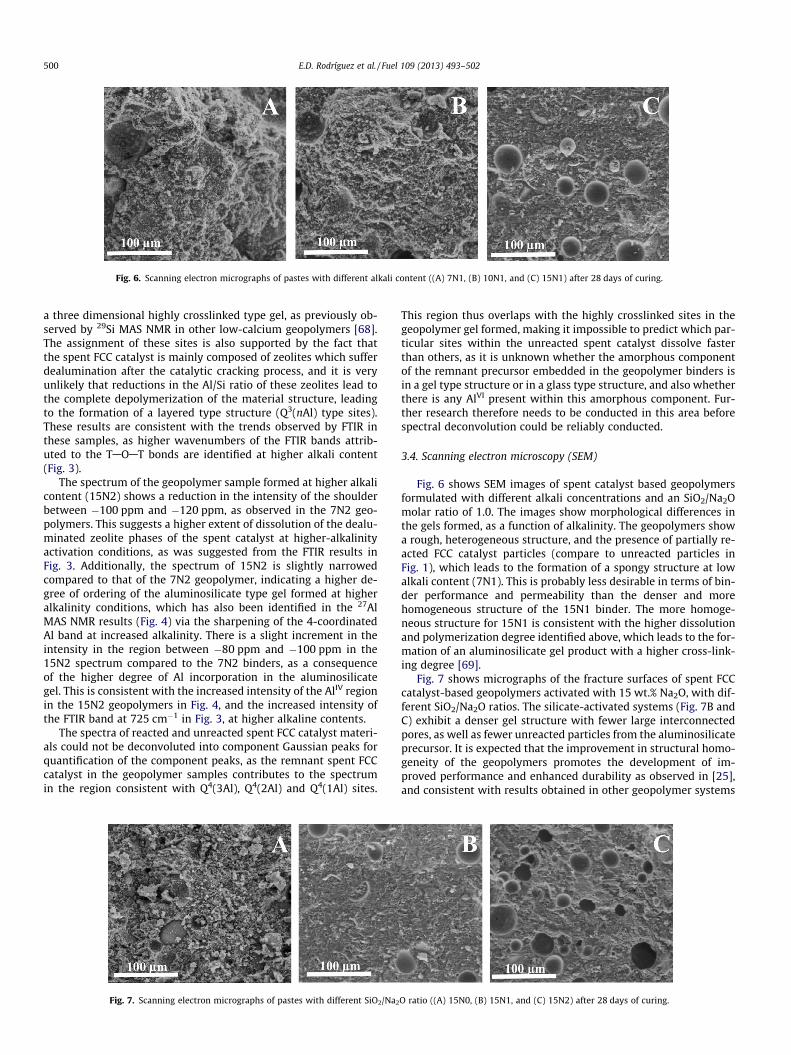
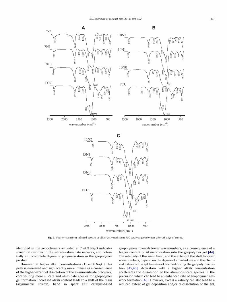
Fig. 6. Scanning electron micrographs of pastes with different alkali content ((A) 7N1, (B) 10N1, and (C) 15N1) after 28 days of curing.
500 E.D. Rodríguez et al. / Fuel 109 (2013) 493–502
a three dimensional highly crosslinked type gel, as previously ob-served by 29Si MAS NMR in other low-calcium geopolymers [68].The assignment of these sites is also supported by the fact thatthe spent FCC catalyst is mainly composed of zeolites which sufferdealumination after the catalytic cracking process, and it is veryunlikely that reductions in the Al/Si ratio of these zeolites lead tothe complete depolymerization of the material structure, leadingto the formation of a layered type structure (Q3(nAl) type sites).These results are consistent with the trends observed by FTIR inthese samples, as higher wavenumbers of the FTIR bands attrib-uted to the TAOAT bonds are identified at higher alkali content(Fig. 3).
The spectrum of the geopolymer sample formed at higher alkalicontent (15N2) shows a reduction in the intensity of the shoulderbetween �100 ppm and �120 ppm, as observed in the 7N2 geo-polymers. This suggests a higher extent of dissolution of the dealu-minated zeolite phases of the spent catalyst at higher-alkalinityactivation conditions, as was suggested from the FTIR results inFig. 3. Additionally, the spectrum of 15N2 is slightly narrowedcompared to that of the 7N2 geopolymer, indicating a higher de-gree of ordering of the aluminosilicate type gel formed at higheralkalinity conditions, which has also been identified in the 27AlMAS NMR results (Fig. 4) via the sharpening of the 4-coordinatedAl band at increased alkalinity. There is a slight increment in theintensity in the region between �80 ppm and �100 ppm in the15N2 spectrum compared to the 7N2 binders, as a consequenceof the higher degree of Al incorporation in the aluminosilicategel. This is consistent with the increased intensity of the AlIV regionin the 15N2 geopolymers in Fig. 4, and the increased intensity ofthe FTIR band at 725 cm�1 in Fig. 3, at higher alkaline contents.
The spectra of reacted and unreacted spent FCC catalyst materi-als could not be deconvoluted into component Gaussian peaks forquantification of the component peaks, as the remnant spent FCCcatalyst in the geopolymer samples contributes to the spectrumin the region consistent with Q4(3Al), Q4(2Al) and Q4(1Al) sites.
Fig. 7. Scanning electron micrographs of pastes with different SiO2/Na2
This region thus overlaps with the highly crosslinked sites in thegeopolymer gel formed, making it impossible to predict which par-ticular sites within the unreacted spent catalyst dissolve fasterthan others, as it is unknown whether the amorphous componentof the remnant precursor embedded in the geopolymer binders isin a gel type structure or in a glass type structure, and also whetherthere is any AlVI present within this amorphous component. Fur-ther research therefore needs to be conducted in this area beforespectral deconvolution could be reliably conducted.
3.4. Scanning electron microscopy (SEM)
Fig. 6 shows SEM images of spent catalyst based geopolymersformulated with different alkali concentrations and an SiO2/Na2Omolar ratio of 1.0. The images show morphological differences inthe gels formed, as a function of alkalinity. The geopolymers showa rough, heterogeneous structure, and the presence of partially re-acted FCC catalyst particles (compare to unreacted particles inFig. 1), which leads to the formation of a spongy structure at lowalkali content (7N1). This is probably less desirable in terms of bin-der performance and permeability than the denser and morehomogeneous structure of the 15N1 binder. The more homoge-neous structure for 15N1 is consistent with the higher dissolutionand polymerization degree identified above, which leads to the for-mation of an aluminosilicate gel product with a higher cross-link-ing degree [69].
Fig. 7 shows micrographs of the fracture surfaces of spent FCCcatalyst-based geopolymers activated with 15 wt.% Na2O, with dif-ferent SiO2/Na2O ratios. The silicate-activated systems (Fig. 7B andC) exhibit a denser gel structure with fewer large interconnectedpores, as well as fewer unreacted particles from the aluminosilicateprecursor. It is expected that the improvement in structural homo-geneity of the geopolymers promotes the development of im-proved performance and enhanced durability as observed in [25],and consistent with results obtained in other geopolymer systems
O ratio ((A) 15N0, (B) 15N1, and (C) 15N2) after 28 days of curing.

E.D. Rodríguez et al. / Fuel 109 (2013) 493–502 501
based on different aluminosilicate precursors, such as metakaolin[68] and fly ashes [35]. The increase in the silica content from sys-tem 15N1 to 15N2 does not show to promote significant differ-ences in the gel structure, but the less favorable rheology of thehighest-silica system seems to have led to the inclusion of a greaternumber of relatively large air bubbles in this specimen.
4. Conclusions
This study has demonstrated the potential of a zeolite-basedspent fluid catalytic cracking catalyst as an effective precursor forthe production of geopolymer binders. In these systems, the rem-nant dealuminated zeolites in the unreacted spent residue arereadily dissolved, even when activation is carried out under rela-tively low alkalinity conditions, indicating the high reactivity ofthis precursor during the alkali-activation reaction. Increased alkalicontents lead to the formation of a highly dense and crosslinkedaluminosilicate type gel, when compared with the gels formed atlower alkali content, which were enriched in Si and present arather heterogeneous structure with interconnected pores. This isrelated to the high alkalinity required to promote the dissolutionof the AlO�4 species from the distorted zeolite structures and otherphases present in the spent catalyst. This is consistent with the factthat independent of the alkali content, an increased reactive SiO2/Al2O3 ratio promotes the formation of highly crosslinked Si-en-riched type gels with low Al content. This work then providesthe basis for further developments in this area, as a means of val-orizing spent fluid catalytic cracking catalyst residues into usefulgeopolymer materials.
Acknowledgments
This study was sponsored by research scholarship BES-2008-002440 and EEBB-2011-43847 from the Ministerio de Ciencia y Tec-nología of Spain, the European regional development fund (FEDER),and the Universitat Politècnica de València (Spain). The participationof SAB and JLP was funded by the Australian Research Councilthrough the Discovery Projects program, and also including partialfunding through the Particulate Fluids Processing Centre, a SpecialResearch Centre of the ARC. The authors wish to acknowledge theAdvanced Microscopy Facility at The University of Melbourne forassistance with the electron microscopy experiments conductedin this study.
References
[1] EIA Independent Statistics & Analysis. US Energy Information Administration.Short-term energy, outlook. September 2012.
[2] Speight JG. The chemistry and technology of petroleum. 4th edition. NewYork: CRC Press. Taylor & Francis Group, LLC; 2006.
[3] Marafi M, Stanislaus A, Furimsky E. Handbook of spent hydroprocessingcatalysts: regeneration, rejuvenation, reclamation, environment and safety. 1sted. The Netherlands: Elsevier: Amsterdam; 2010.
[4] Schreiber R, Yonley G. The use of spent catalyst as a raw material substitute incement manufacturing. ACS Petrol Chem Div 1993;38:97–9 [Preprints].
[5] Lin J, Tarn J, Yu D, Hsiao L. Utilization of ROC spent catalyst on asphalt concrete.In: International Conference on Industrial Waste Minimization. Taiwan; 1995,p. 667–74.
[6] Escardino A, Amoros J, Moreno A, Sanchez E. Utilizing the used catalyst fromrefinery FCC units as a substitute for kaolin in formulating ceramic frits. WasteManag Res 1995;13:569–78.
[7] Basaldellaa EI, Torres RM, Conconi MS. Conversion of exhausted fluid crackingcatalysts into zeolites by alkaline fusion. Appl Clay Sci 2009;42:611–4.
[8] Al-Sheeha H, Marafi M, Stanislaus A. Reclamation of alumina as boehmite froman alumina-supported spent catalyst. Int J Miner Process 2008;88:59–64.
[9] Sun DD. Stabilization treatment for reutilization of spent refinery catalyst intovalue-added product. Energy Source 2003;25:607–15.
[10] Stonys R, Pundiene I, Antonovic V, Goberis S, Aleknevicius M. The effect ofwaste oil-cracking catalyst on the properties of MCC-type castable. Mater Sci-Medzg 2008;14:59–62.
[11] Pacewska B, Wilinska I, Kubissa J. Use of spent catalyst from catalytic crackingin fluidized bed as a new concrete additive. Thermochim Acta1998;322:175–81.
[12] Payá J, Monzó J, Borrachero MV. Fluid catalytic cracking catalyst residue(FC3R): an excellent mineral by-product for improving early-strengthdevelopment of cement mixtures. Cem Concr Res 1999;29:1773–9.
[13] Chen H-L, Tseng Y-S, Hsu K-C. Spent FCC catalyst as a pozzolanic material forhigh-performance mortars. Cem Concr Compos 2004;26:657–64.
[14] Dweck J, Pinto CA, Buchler P. Study of a Brasilian spent catalyst as cementaggregate by thermal and mechanical analysis. J Therm Anal Calorim2008;92:121–7.
[15] García de Lomas M, Sánchez de Rojas M, Frías M. Pozzolanic reaction of a spentfluid catalytic cracking catalyst in FCC-cement mortars. J Therm Anal Calorim2007;90:443–7.
[16] Glasser FP, Zornoza E, Garcés P, Payá J, Brew DRM. Pozzolanic activity of aspent fluid catalytic cracking catalyst residue. Adv Cem Res 2011;23:105–11.
[17] Bayraktar O. Bioleaching of nickel from equilibrium fluid catalytic crackingcatalysts. World J Microb Biot 2005;21:661–5.
[18] Pacewska B, Wilinska I, Bukowska M, Blonkowski G, Nocun-Wczelik W. Anattempt to improve the pozzolanic activity of waste aluminosilicate catalyst. JTherm Anal Calorim 2004;77:133–42.
[19] Hsu K-C, Tseng J-S, Ku F-F, Su N. Oil cracking waste catalyst as an activepozzolanic material for superplasticized mortars. Cem Concr Res2001;31:1815–20.
[20] Payá J, Monzó J, Borrachero MV, Velázques S. Chemical activation of pozzolanicreaction of fluid catalytic cracking catalyst residue in lime pastes. Adv Cem Res2004;16:123–30.
[21] Roy DM. Alkali-activated cements Opportunities and challenges. Cem ConcrRes 1999;29:249–54.
[22] van Deventer JSJ, Provis JL, Duxson P. Technical and commercial progress in theadoption of geopolymer cement. Miner Eng 2012;29:89–104.
[23] Provis JL, van Deventer JSJ. Geopolymers: structure, processing, properties andindustrial applications. Cambridge: Woodhead Publishing; 2009.
[24] Duxson P, Provis JL. Designing precursors for geopolymer cements. J Am CeramSoc 2008;91:3864–9.
[25] Tashima MM, Akasaki JL, Castaldelli VN, Soriano L, Monzó J, Payá J, et al. Newgeopolymeric binder based on fluid catalytic cracking catalyst residue (FCC).Mater Lett 2012;80:50–2.
[26] Payá J, Monzó J, Borrachero MV, Velázquez S, Bonilla M. Determination of thepozzolanic activity of fluid catalytic cracking residue. Thermogravimetricanalysis studies on FC3R–lime pastes. Cem Concr Res 2003;33:1085–91.
[27] Payá J, Monzó J, Borrachero MV, Mellado A, Ordoñez LM. Determination ofamorphous silica in rice husk ash by a rapid analytical method. Cem Concr Res2001;31(2):227–31.
[28] Kolesnikov IM, Frolova IN. Production and activity of sillimanite andsillimanite-zeolite aluminosilicate catalyst. J Appl Chem USSR1982;55:561–71.
[29] Reagan WJ, White DW, Schultz WR, Jarnagin LA, Pitts F. Mullite/silica contactmaterial, its production, and its use in selective vaporization of petroleumfeedstock, European Patent EP 0185551; 1986.
[30] Liu C, Deng Y, Pan Y, Zheng S, Gao X. Interactions between heavy metals andclay matrix in fluid catalytic cracking catalysts. Appl Catal A-General2004;257:145–50.
[31] Fernández-Jiménez A, Delatorre A, Palomo A, Lopezolmo G, Alonso M, ArandaM. Quantitative determination of phases in the alkali activation of fly ash PartI. Potential ash reactivity. Fuel 2006;85:625–34.
[32] Rahier H, Mele B, Biesemans M, Wastiels J, Wu X. Low-temperaturesynthesized aluminosilicate glasses. J Mater Sci 1996;31:71–9.
[33] Rahier H, Simons W, Van Mele B, Biesemans M. Low-temperature synthesizedaluminosilicate glasses: part III influence of the composition of the silicatesolution on production, structure and properties. J Mater Sci1997;32:2237–47.
[34] De Silva P, Sagoe-Crenstil K. Medium-term phase stability of Na2O–Al2O3–SiO2–H2O geopolymer systems. Cem Concr Res 2008;38:870–6.
[35] Criado M, Fernández-Jiménez A, de la Torre A, Aranda M, Palomo A. An XRDstudy of the effect of the SiO2/Na2O ratio on the alkali activation of fly ash. CemConcr Res 2007;37:671–9.
[36] van Deventer JSJ, Provis JL, Duxson P, Lukey GC. Reaction mechanisms in thegeopolymeric conversion of inorganic waste to useful products. J Hazard Mater2007;139:506–13.
[37] Farmer VC. The infrared spectra of minerals. London: Royal Society; 1974.[38] Gadsden JA. Infrared spectra of minerals and related inorganic
compounds. London, U.K.: Butterworth; 1975.[39] Bugaev LA, van Bokhoven JA, Sokolenko AP, Latokha YV, Avakyan LA. Local
structure of aluminum in zeolite mordenite as affected by temperature. J PhysChem B 2005;109:10771–8.
[40] Miessner H, Kosslick H, Lohse U, Parlitz B, Tuan VA. Characterization of highlydealuminated faujasite-type zeolites: ultrastable zeolite Y and ZSM-20. J PhysChem 1993;97:9741–8.
[41] Masukawa T, Komatsu T, Yashima T. Alkylation of toluene on HSAPO-5 withvarious Si concentrations. Zeolites 1997;19:429–33.
[42] Li B, González RD. An in situ DRIFTS study of the deactivation and regenerationof sulfated zirconia. Catal Today 1998;46:55–67.
[43] Damjanovic L, Auroux A. Determination of acid/base properties bytemperature programmed desorption (TPD) and adsorption calorimetry. In:

502 E.D. Rodríguez et al. / Fuel 109 (2013) 493–502
Chester AW, Derouane EG, editors. Zeolite characterization andcatalysis. Netherlands: Springer. p. 107–67.
[44] Flanigen EM. Structural analysis by infrared spectroscopy. In: ZeoliteChemistry and Catalysis. American Chemical Society, ACS Monograph Series:Washington (DC); 1976.
[45] Rees CA, Provis JL, Lukey GC, van Deventer JSJ. Attenuated total reflectanceFourier transform infrared analysis of fly ash geopolymer gel aging. Langmuir2007;23:8170–9.
[46] Rees CA, Provis JL, Lukey GC, van Deventer JSJ. In Situ ATR-FTIR study of theearly stages of fly ash geopolymer gel formation. Langmuir 2007;23:9076–82.
[47] Lecomte I, Henrist C, Liégeois M, Maseri F, Rulmont A, Cloots R. (Micro)-structural comparison between geopolymers, alkali-activated slag cement andPortland cement. J Eur Ceram Soc 2006;26:3789–97.
[48] Zhang Z, Wang H, Provis JL, Bullen F, Reid A, Zhu Y. Quantitative kinetic andstructural analysis of geopolymers. Part 1. The activation of metakaolin withsodium hydroxide. Thermochim Acta 2012;539:23–33.
[49] Fernández-Jiménez A, Palomo A. Mid-infrared spectroscopic studies of alkali-activated fly ash structure. Micropor Mesopor Mater 2005;86:207–14.
[50] Fernández-Jiménez A, Palomo A, Sobrados I, Sanz J. The role played by thereactive alumina content in the alkaline activation of fly ashes. MicroporMesopor Mater 2006;91:111–9.
[51] Devine RAB. Ion implantation- and radiation-induced structural modificationsin amorphous SiO2. J Non-Cryst Solids 1993;152:50–8.
[52] Liu X. Infrared and Raman spectroscopy. In: Chester AW, Derouane EG, editors.Zeolite characterization and catalysis. Netherlands: Springer; 2010. p.197–222.
[53] He H, Guo J, Zhu J, Yuan P, Hu C. 29Si and 27Al MAS NMR spectra of mullitesfrom different kaolinites. Spectrochim Acta A 2004;60:1061–4.
[54] Hartman JS, Sherriff BL. Silicon-29 MAS NMR of the aluminosilicate mineralkyanite: residual dipolar coupling to aluminum-27 and nonexponential spin-lattice relaxation. J Phys Chem 1991;95:7575–9.
[55] Engelhardt G, Lohse U, Samoson A, Mägi M, Tarmak M, Lippmaa E. Highresolution 29Si NMR of dealuminated and ultrastable Y-zeolites. Zeolites1982;2:59–62.
[56] Behera B, Ray SS. Structural changes of FCC catalyst from fresh to regenerationstages and associated coke in a FCC refining unit: A multinuclear solid stateNMR approach. Catal Today 2009;141:195–204.
[57] Engelhardt G, Michel D. High-resolution solid-state NMR of silicates andzeolites. New York: John Wiley and Sons; 1987.
[58] Chen T-H, Houthoofd K, Grobet PJ. Toward the aluminum coordination indealuminated mordenite and amorphous silica–alumina: a high resolution27Al MAS and MQ MAS NMR study. Micropor Mesopor Mater 2005;86:31–7.
[59] Rocha J, Carr SW, Klinowski J. 27Al quadrupole nutation and 1H–27Al cross-polarization solid-state NMR studies of ultrastable zeolite Y with fast magic-angle spinning. Chem Phys Lett 1991;187:401–8.
[60] Rakiewicz EF, Mueller KT, Jarvie TP, Sutovich KJ, Roberie TG, Peters AW. Solid-state NMR studies of silanol groups in mildly and highly dealuminatedfaujasites. Micropor Mater 1996;7:81–8.
[61] Merwin LH, Sebald A, Rager H, Schneider H. 29Si and 27Al MAS NMRspectroscopy of mullite. Phys Chem Miner 1991;18:47–52.
[62] Duxson P, Lukey GC, Separovic F, van Deventer JSJ. Effect of alkali cations onaluminum incorporation in geopolymeric gels. Ind Eng Chem Res2005;44:832–9.
[63] Fyfe BCA, Thomas JM, Klinowski J, Gobbi GC. Magic–angle–spinning NMR(MAS–NMR) spectroscopy and the structure zeolites. Angew Chem Int Ed1983;22:259–75.
[64] Gore KU, Abraham A, Hegde SG, Kumar R, Amoureux J-P, Ganapathy S. MAS/3Q-MAS NMR studies of high silica USY zeolites. J Phys Chem B2002;106:6115–20.
[65] Barras J, Klinowski J, Mccomb DW. 27Al and 29Si solid-state NMR studies ofdealuminated mordenite. J Chem Soc Faraday Trans 1994;90:3719–23.
[66] Klinowski J. Recent advances in solid-state NMR of zeolites. Annu Rev MaterSci 1988;18:189–218.
[67] Jaymes I, Massiot D, Coutures J-P. Evolution of the Si environment in mullitesolid solution by 29Si MAS-NMR spectroscopy. J Non-Cryst Solids1996;204:125–34.
[68] Duxson P, Provis JL, Lukey GC, Separovic F, van Deventer JSJ. 29Si NMR study ofstructural ordering in aluminosilicate geopolymer gels. Langmuir2005;21:3028–36.
[69] Duxson P, Provis JL, Lukey GC, Mallicoat SW, Kriven WM, van Deventer JSJ.Understanding the relationship between geopolymer composition,microstructure and mechanical properties. Colloids Surfaces A2005;269:47–58.
Related Documents