Int. J. Rock Me~h. Min. Sci. & Ceometh. Abstr. VoL I0. pp. 133-150. Pergamon Press 1973. Printed in Great Britain A STUDY OF PRESSURIZED UNDERGROUND STORAGE CAVITIES: THEORETICAL AND LABORATORY INVESTIGATIONS D. E. S~SKINO,* H. R. HARDY JR~" and S. S. ALEXANDER~ (Received 20 May 1972) Abstract--The increasing u~ of oil and gas reservoir traps, salt cavities and other man-made underground cavities for the storage of natural gas and other fluids necessitates a better understanding of the loading and failure characteristics of such storage areas. In the present study cylindrical models containing miniature reservoir cavities were fabri- cated for the experimental simulation of storage reservoir behavior. These were loaded under typical in situ stress fields and subjected to internal pressurization. Tangential and radial stresses on the cavity walls were inferred from theoretical solutions and the known boundary condi- tions and were compared with those predicted from measured levels of acot,stic emission. The reservoir failures observed were tensile in form and occurred as predicted at/or near the north or south poles of the cavities. The internal pressures necessary to cause reservoir failure, however, were about 2-8-3"0 tintcs those predicted on the expectation of failure occurring when the tangential tensile stresses exceed the tensile strength of the rock surroundingthecavity. It was observed that the onset of acoustic emission began early in the pressurization cycle, at about one third of the pressure required for the eventual ultimate faihnre of the model. The acoustic activity and high failure pressures observed indicated that some kind of stress- relieving inelastic phenomenon probably commenced at a relatively low pressure, with the ultimate I~ilure, easily recognized by the sudden drop in reservoir pressure, occurring con- siderably later. Tltese results stnggcst the possible use of acoustic emission as a useful means of monitoring reservoir stability in both models and full-scale field structures. I. INTRODUCTION THE analysis of the failure characteristics of underground cavities is critical to many lields of mining, petroleum and natural gas, and civil engineering. Until recently interest in the stress conditions of such cavities has been mainly motivated by the desire to better understand the mechanisms associated with rockbursts and roof collapse. With the widespread practice of storing gas in natural and man-made underground cavities, knowledge of the behavior of such cavities under internal pressurization has also become of considerable practical importance. The present study was established to evaluate the failure parameters of internally pres- surized openings in rock-like materials under typical in situ triaxial stress conditions. The overall state of stress in the vicinity of the cavities was calculated by utilizing available theoretical solutions and previous experimental work. The level of acoustic emission (microseismic activity) occurring during loading was monitored to give indications of reservoir instability during testing and possible prediction of impending failure. The model * Twin Cities Mining Research Center, U.S, Bureau of Mines. Twin Cities, Minnesota. t Department of Mineral Engineering, The Pennsylvania State Unive~ity, University Park, Pennsylvania. Department of Geosciences, The Pennsylvania State University, University Park, Pennsylvania. R.Ch: lO/2--r, 133

1-s2.0-0148906273900521-main
Dec 11, 2015
doc
Welcome message from author
This document is posted to help you gain knowledge. Please leave a comment to let me know what you think about it! Share it to your friends and learn new things together.
Transcript

Int. J. Rock Me~h. Min. Sci. & Ceometh. Abstr. VoL I0. pp. 133-150. Pergamon Press 1973. Printed in Great Britain
A STUDY OF PRESSURIZED UNDERGROUND STORAGE CAVITIES: THEORETICAL AND LABORATORY
INVESTIGATIONS
D. E. S~SKINO,* H. R. HARDY JR~" and S. S. ALEXANDER~
(Received 20 May 1972)
Abstract--The increasing u~ of oil and gas reservoir traps, salt cavities and other man-made underground cavities for the storage of natural gas and other fluids necessitates a better understanding of the loading and failure characteristics of such storage areas.
In the present study cylindrical models containing miniature reservoir cavities were fabri- cated for the experimental simulation of storage reservoir behavior. These were loaded under typical in situ stress fields and subjected to internal pressurization. Tangential and radial stresses on the cavity walls were inferred from theoretical solutions and the known boundary condi- tions and were compared with those predicted from measured levels of acot, stic emission.
The reservoir failures observed were tensile in form and occurred as predicted at/or near the north or south poles of the cavities. The internal pressures necessary to cause reservoir failure, however, were about 2-8-3"0 tintcs those predicted on the expectation of failure occurring when the tangential tensile stresses exceed the tensile strength of the rock surroundingthecavity. It was observed that the onset of acoustic emission began early in the pressurization cycle, at about one third of the pressure required for the eventual ultimate faihnre of the model.
The acoustic activity and high failure pressures observed indicated that some kind of stress- relieving inelastic phenomenon probably commenced at a relatively low pressure, with the ultimate I~ilure, easily recognized by the sudden drop in reservoir pressure, occurring con- siderably later. Tltese results stnggcst the possible use of acoustic emission as a useful means o f monitoring reservoir stability in both models and full-scale field structures.
I. INTRODUCTION
THE analysis of the failure characteristics of underground cavities is critical to many lields of mining, petroleum and natural gas, and civil engineering. Until recently interest in the stress
condi t ions of such cavities has been mainly motivated by the desire to better unders tand the mechanisms associated with rockbursts and roof collapse. With the widespread practice of
storing gas in natural and man-made underground cavities, knowledge of the behavior of such cavities under internal pressurization has also become of considerable practical importance.
The present study was established to evaluate the failure parameters of internally pres- surized openings in rock-like materials under typical in s i tu triaxial stress conditions. The overall state of stress in the vicinity of the cavities was calculated by utilizing available
theoretical solutions and previous experimental work. The level of acoustic emission (microseismic activity) occurring dur ing loading was monitored to give indications of reservoir instability during testing and possible prediction of impending failure. The model
* Twin Cities Mining Research Center, U.S, Bureau of Mines. Twin Cities, Minnesota. t Department of Mineral Engineering, The Pennsylvania State Unive~ity, University Park, Pennsylvania.
Department of Geosciences, The Pennsylvania State University, University Park, Pennsylvania. R.Ch: lO/2--r, 133

134 D.F.. $ISKIND, H. R. HARDY JR AND S. S. ALEXANDER
cavity shapes tested were restricted to spherical and spheroidal due to the limited avail- ability of theoretical solutions for even simple geometric-shaped cavities under conditions of triaxial stress.
The studies carried out have been specifically orientated towards investigation of the stability of underground gas-storage r-~rvoirs; however, the results arc applicable to a wide range of engineering and g e o l ~ sRuations.
2. UNDIgRGROUND STORAGE
Generally, a gas-storage reservoir consists of a region of relatively high porosity and permeability, bounded on top and in some way on the sides by an extremely low perme- ability rock (cap rock). Most reservoirs are old gas and oil areas and are associated with structural or stratisraphic traps, in many cases, the rock surrounding thc trap is saturated with water up to the water table, and as a result, the pressure of the contained liquid and/or gas is equal to the hydrostatic head. In a relatively few traps, the original reservoir pressures are abnormal due to hydrodynamic or nonequitibrium conditions. Normally, the pressures used in gas-storage reservoirs approximate the original well discovery pres- sures, but a small number exceed these values by up to 30 per cent. A typical simple reservoir is exemplified by the Herscher Dome in Illinois, a structural trap that has been used for long-term gas storage (Em>oN[I ]) for some years.
3. ACOUSTIC EMISSION TECHNIQUES
Acoustic emission or microseismic techniques have become invaluable tools in geophysics and rock mechanics. Such techniques are considered as the basis of a promising ~ for advanced detection of impending structural failure in studies on large-scale phenomena such as failure of mine openings and microearthquakes (OUEaT and DUVALL [2], CttANDALL [3], and OUVEa, RYALL and BaUNE [4] and in studies on small-scale structures in the labor- atory (GOODMAN [5], SOIOLZ [6] and HANDY et ai. [7]). Acoustic emission techniques have been used to locate failure planes (Scnot~ [8]) and the incidence ofcreep (HANDY et al. [7]). Studies have also been made in an attempt to correlate acoustic emission and failure hLqory (GoOnMAN [5], CHUGH, HANDY and STEFAr'~gO [9]). A summary of acoustic emission techniques is given by KNILL, FRANKLIN and MALONE [!0].
In the present studies acoustic emission was used to detect the pressure at which initial cavity failure occurred. This technique could also be used to locate the point of failure (focus) in the model, but this was not practical in the present study because of ~lUipment limitations and the small size of the reservoir models. [nstead the failure location and characteristics were investigated by direct visual examination of the model following the completion of each test.
4. THEORETICAL SOLUTIONS
(a) Introduction
In order to evaluate the stresses in the vicinity of an otmning in a material subjected to a triaxial stress field, it is necessary to obtain a suitable solution to the general three-dimen- sional elasticity equations (Oseax and DUVALL [2], SADOWSKY and S~ttNIEaG It 1] and Tr.azAGm and RtCtO, RT [12]). The st~sses associated with a three-dimensional ~ i n g in a uniaxial stress field are given by OaEaT and DUVALL [2]. In the past, considerable work

A STUDY OF PRESSURIZED UNDERGROUND STORAGE CAVITIES 135
has been done in two-dimensions, both experimentally and mathematically: however, the problems investigated have generally been less complex than that considered in the present study. It should be pointed out here that as engineering approximations, two-dimensional solutions are commonly applied to three-dimensional openings of similar cross section, with the additional closure in the third dimension and the corresponding added supporting effect giving a built-in safety factor.
In the present study, the less complex case of a spherical cavity was considered and the results extrapolated to flattened openings (e.g. spheroids or ellipsoids of revolution). The medium was assumed to be homogeneous, isotropic and strictly elastic in all cases. The general solution for a nonspherical cavity under internal pressurization was not derived because of its complexity and since a two-dimensional finite-element solution was available (HARDY and CHUGH [13]).
(b) The spherical opening
The problem of a spherical cavity in a triaxiai stress field requires the superposition of three solutions of the uniaxial stress equation with linearity assumed. In the current study, the overburden load was considered to be the major cause of the in situ vertical field (S:) and the in situ horizontal stresses were considered due only to the effects of lateral con- straint. The uniaxial solutions used assume the existence of a uniform in situ vertical stress
Sur foce
tt t i " / ! , , I ~ ,~..% / r I
oL ,-':;A,,:Y, i / " \ I ; /11 :I
L
~ S y
"y
Fl(;. I. Spherical cavity loaded by itt .~itu ground stresses.
field in the vicinity of the cavity, and that all free surfaces are relatively remote. Figure ! shows the coordinate system and the sign convention as adopted from OaERT and DUVALL [2] with tension being defined as positive in sign. Here the vertical component of the in situ stress field is given by the following:
s : = s v = - p g z (1)
where p is the average density of the overlying rock, z is the depth and g is the gravitational

136 D. E. SISKIND. 14_ R. HARDY JR AND S. S. ALEXANDER
constant. The condition of complete lateral constraint allows the horizontal m'ess field to be calculated from the following:
s . = s° (2)
where v is Poisson's ratio and S, is the in situ vertical field defined in equation (i). The str--~ses for the region around spherical opening in a uniaxiai stress field are given
by OUmT and DUVALL [2] as
[( s , 10v - 14 + (50 - 100a ~ *" = 14 '-- 10v r~ rS sin 2 0
- r3 + - ~ - / j (3)
[( o . = 1 4 - I--------~ r z + r 5 J sin20
( ( 9 - - 1 5 , ) a ' 12a'~ ] + r3 r s / j (4)
[( S~ (30v-- 15)a 3 + - ~ ] sin" 0 u, - - - - - 1 4 - - lOv " r 3
1 + f i r ~ I J (5)
S= [ 1 0 v - 1 4 - ( 1 0 - 10~)a 3 24a s] *"* -~ 14 -- 10v r ~ + ~ ] sin 0 cos 0 (6)
. . , - ~-,, = 0 (7)
where a is the radius of the spherical cavity and the other factors have been defined earlier (see Fig. 1).
To obtain equations applicable to triaxiai loading three solutions of the uniaxial form just presented corresponding to the x, y and x-dh '~t iom are combined, and the appropriate expressions for the in situ stresses sutmtit~.ed from equatimts (I) and (2). M a ~ m u m stresses are considered to occur on the cavity wall (r ~ a), and under this condition, equations (4) and (5) reduce to the following:
S, [ v (30 cos" 0 -- 6)] (8) =" = 14 - - 10~, (30 sin 2 0 - - 151, - - 3 ) + 1 i ~
S. (30v sin 2 0 -- 15, - - 3~ + ~ (30, cos 0 -- 30v + . (9) ere = 1 4 _ 10 v
It should be noted that under these conditions, all other stress components are identically zero.
Values of*alSo and ,~]So are plotted in Figs 2 and 3 for a range of Poisson's ratio values. Most noticeable is the tendency toward tensile-type stress concentrations i n ~ ' p o l c regions"
0 ° (0 ----- 0 or 18&), and large compressive sums concentrations at the eqtmtor (, ----- 90 ).

A S T U D Y O F P R E S S U R I Z E D U N D E R G R O U N D S T O R A G E CAVITIES 137
u : 0-20
u 0 50 u =0 ~ - - u ' L - O . 3 0
15 u '= 0-40
/ / =o4o/I
J E
.8 E
30 60 90 Angle 0, deg.
Fit;. 2. Variat ion of the tangential stress concentration factor (%/S,,) on the wall o f a spherical cavity wi th O for a number o f values of Poisson's ratio.
t ~
~3
o
~ -e 5
Yl u :0-50
u=O
, ~ I ~ f I r f I 0 50 60 90
Angle e, deg.
I-to;. 3. Variat ion o f the tangential stress concentra t ion factor (%/Sv) on the wall o f a spherical cavity with 0, for a number o f values o f Poisson ' s ratio.
138 D. E. SISKIND, H. R. H A R D Y JR A N D S. S. A L E X A N D E R
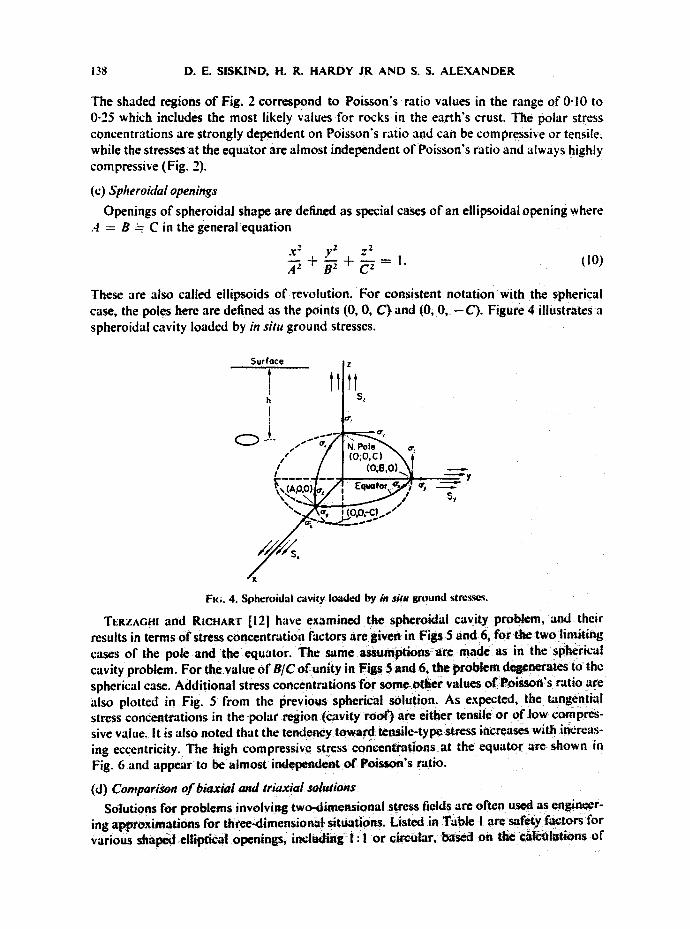
The shaded regions of Fig. 2 correspond to Poisson's ratio values in the range of 0-10 to 0-25 which includes the most likely values for rocks in the earth's crust. The polar stress concentrations are strongly dependent on Poisson's ratio and can be compressive or tensile. while the stresses at the equator are almost independent of Poisson's ratio and always highly compressive (Fig. 2).
(c) Spheroidal openings
Openings of spherokial shape are defined as special cases of an ellipsoidal opening where ,4 - - B ~ C in the general equation
X2 y2 Z2 ,4 + I. (lO)
These are also called ellipsoids of revolution. For consistent notation with the spherical case, the poles here are defined as the points (0, 0, C) and (0, 0, - C ) . Figure 4 illustrates a spheroidal cavity loaded by in sire ground stresses.
Surface! - I llil ~
s, "-.~AF, i (o,o;-c!...-"
Fl(;. 4. Spheroidal cavity Ioad~J by be situ ground strc'~.sc~.
TERZAG,! and RICtlAe'r [12] have examined the spheroidal cavity problem, and their results in terms of stress concentration factors are given in Figs 5 and 6, for the two limiting cases of the poic and the equator. The same assumptions arc made as in the spherical cavity problem. For the value of B/C of unity in Figs 5 and 6, the problem de~,'z~ra~es to the spherical ease. Additional stress concentrations for some other values of Poisson's ratio arc also plotted in Fig. 5 from the previous spherical solution. As expected, the tangential stress concentrations in the polar region (cavity roof) are either tensile or of low compres- sive vatue, it is also noted that the tendency toward tensile-type stress increases with increas- ing eccentricity. The high compressive stress concentrations at the equator are shown in Fig. 6 and appear to be almost independent of Poisson's ratio.
(d) Comparison of biaxial and triaxial solutions Solutions for problems involving two-dimensional stress fields arc often used as engineer-
ing approximations for three-dimensional situations. Listed in Table I arc safety factors for various shaped elliptical openings, i n c l ~ n g t : 1 or circular, based on the catcalatiOns of

A STUDY OF PRESSURIZED U N D E R G R O U N D STORAGE CAVITIES 139
z
, 5
?. ,.o- \.=o.so i: 2B "I ~ •Sphericol data
"~ "u=O u=0.20
I 2 5 tO 20 50 Eccentricity, B/C
F=(;. 5. Variation of the tangential stress concentration factor (~,,/S,.) at the poles of a spheroidal cavity for various eccentricities. (After TEaz^(;m and RICHART [12].)
20
15
u=O.511u-'O.2
E o
o
.g
/
! 2 5 I0 20 50
Eccentricity, B/C
Fie;. 6. Variation o f the tangential s tress concentra t ion factor (~,/S,) at the equa tor o f a spheroidal cavity for various eccentricities (After T~az^ ( ;m and RICH^R'r [12].)

140 D. E. SISKIND, H. IL HARDY JR AND S. S. ALEXANDER
TABLE I . STRESS CONCF.NTRATION$ ~' AND SAFETY FACTORS FOR
TWO-AND THREIE-DIME~iONAL ELLIPTICAL OPENINGS AND TUNNELS
(After TERZAGHI and RICHART [12l)
(A) Tangential stress concentration (~,/S,) at pole (O = 0) Ellipticity Safety
(B/A) Tunnel (2D) Cavity (3D) factor+
I : I --0-25 0.00 - - 1 : 2 0-50 0-20 2'5 I : 4 0"63 0"30 2- I I : I0 -0-70 -0.37 I-9 I : 20 -0-73 -0-40 1"8 I : 50 0.74 0"42 1"8
(B) Tangential stress concentration (adS¢) at equator (0 = 90 ) Ellipticity Safety
(B/A) Tunnel (2D) Cavity (3D) factor+
I:1 L2.7 -~2.0 1'4 1:2 4-4-8 n-3"2 1.5 I : 4 --12 ~7.0 I-7 I : I 0 - - 2 2 - 13 1"7 1:20 --43 ~25 1.7 I : 50 --- 105 ~- 65 1"7
* IkL~d on calculations where ~ = 0"2. Ratio of stress concentration factors in two-dimensions to those in three-dimensions.
TERZAGItl and RICtIAR'r [12J. These safety factors represent the differences between the stress concentrations for a two-dimensional opening (i.e. a tunnel) and a three-dimensional cavity o f similar vertical cross-sectional shape, for a Poisson's ratio o f 0-20.
(e) Additional stress fieid considerations
in the experimental phase o f the present study, a loading and failure cycle was completed within a few minutes, and the material was assumed to b¢ strictly elastic. I n preliminary runs on solid test specimens, strain m©asurcm©nts showed no inelastic behavior o r creep over time periods o f l0 rain and under uniaxial loads o f up to 1000 psi (50 per cent o f the ultimate strength). Dur ing the pressurization o f real underground rc~rvoirs , it is expected that inelastic yielding and stress transfer may occur, and as a result, influenccth¢ form o f the failure mechanism. The probabili ty o f occurrence ogstress reticf will however tend to incrc.as¢ the saf©ty factor in large reservoirs, with the transfer o f high local stresses into regions o f greater volume and a consequent reduct ion in the level o f stress conc©ntratiom.
It should be reiterated that a number o f simplifying assumptions were made in the analysis presented which involve the nature o f the al~)iied stress field. MCNlVEN and EWOLDS~ [14] recognize five pass /bi t hor izontal fields, i a ¢ ~ ~-adicm stress fields and the relatively new concept o f residual tectonic stresses. T h a ¢ solutions are not directly related to the present experimental study but should be comldcrcd , if possible, in the evaluat ion o f field
conditions.

A STUDY OF PRESSURIZED UNDERGROUND STORAGE CAVITIES 141
( f~ Internal pressurization In order to evaluate the behavior of an underground cavity for storage, it is necessary to
obtain equations which express the behavior of the cavity under internal pressure. For the case of a relatively deep cavity, simple approximations for spherical and cylindrical (tunnel- like) openings can be made, with the surrounding medium again assumed to be isotropic and homogeneous.
An approximation for a spherical opening under internal pressure can be derived from the solution of the well-known thick-walled sphere problem (PRESCOTT [15] and TIMOSHENKO and GOODIER [16]), where an internal pressure (--p~) generates normal and tangential stresses as follows:
p, a 3 ( b3 ) or,=-- b a _ a ~ ~-3-- I (11)
a , = O 0 = b 3 _ a 3 ! + 112)
where a and b are the inside and outside radii of the hollow sphere. If it is assumed that the outer boundary is remote from the cavity (i.e. b >/ 4a), and if
only the stresses on the cavity boundary are of interest (r : a), then equations (I I) and {12) reduce to the following:
a, = -- pj (13)
ao -,~ % =: (I/2) pi. 114)
The general equations for :in open-ended thick-walled cylinder under internal pressure are as follows:
o, = b V LSa 2 -
_. Pia-" ! + (16) oo b.rSSa2
o: = 0 (17)
where a and b are the i,mer and outer radii. By a reduction analogous to the spherical case described earlier, equations (I 5) and (16)
reduce to
o, = -- Pi (18)
°0 = Pl. (19)
In a deep cavity or circular closure that can be approximated by a sphere or a cylinder, equations (13) and (14) or (18) and (19) will apply. These results are sulticiently accurate as a first approximation to represent a number of geologic structures such as symmetrical domes, low plunging anticlinal traps, some salt domes and possibly some stratigraphic traps. They would not however apply to very elongate or flat traps, or to any structures close to the surface.
For an elongate reservoir, such as a broad dome with a relatively small vertical dimension
142 D.E. SISKIND, H. R. HARDY JR AND S. S. ALEXANDER
and for some isolated traps, an elliptical shape could be assumed. In such cases the normal and transverse stresses will be dependent on the angle 0. Such a problem is extremely diffic ult to solve analytically; however, HAar)v and Cttu6tt [13] have successfully applied finite- element techniques to this type of problem (e.g. an internally pressurized elliptical opening in a biaxial stress field).
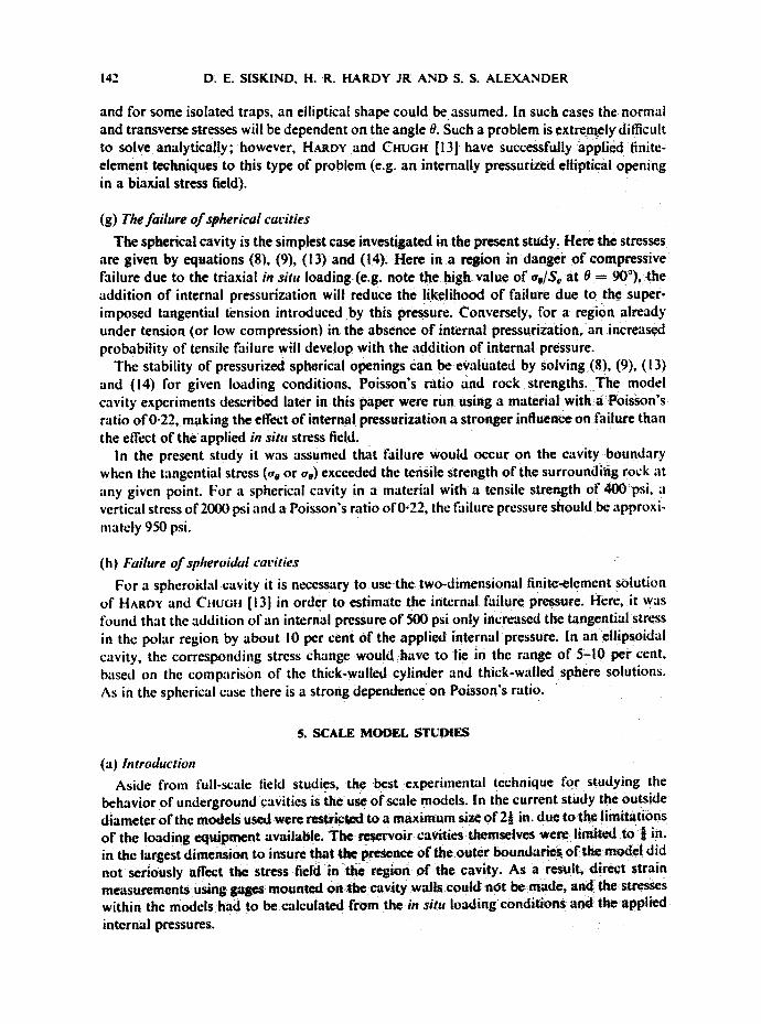
(g) The failure of spherical carities
The spherical cavity is the simplest case investigated in the present study. Here the stresses are given by equations (8), (9), (13) and (14). Here in a region in danger o f compressive failure due to the triaxial in situ loading (e.g. note the high value of oo/S~ at 0 = 90°), the addition of internal pressurization will reduce the likelihood of failure due to the super- imposed tangential tension introduced by this pressure. Conversely, for a region already under tension (or low compression) in the absence o f internal pressurization, an increased probability of tensile failure will develop with the addition of internal pressure.
The stability of pressurized spherical openings can be evaluated by solving (8), (9), (I 3) and (14) for given loading conditions, Poisson's ratio and rock strengths. The model cavity experiments described later in this paper were run using a material with a Poisson's ratio o f 0-22, making the effect of internal pressurization a stronger influence on failure than the effect of the applied in situ stress field.
In the present study it was assumed that failure would occur on the cavity boundary when the tangential stress (% or oe) exceeded the tensile strength of the surrounding rock at any given point. For a spherical cavity in a material with a tensile strength of 400 psi, a vertical stress of 2000 psi and a Poisson's ratio of 0-22, the failure pressure should be approxi- mately 950 psi.
(h) Failure of spheroidal carities
For a spheroidal cavity it is ne~essary to use the two-dimensional finite-element solution of HAar)v and CnuGn [13] in order to estimate the internal failure pressure. Here, it was found that the addition of an internal pressure of 500 psi only increased the tangential stress in the polar region by about l0 per cent of the applied internal pressure. In an eilipsoidal cavity, the corresponding stress change would have to lie in the range of 5-10 per cent, based on the comparison of the thick-walled cylinder and thick-walled sphere solutions. As in the spherical case there is a strong dependence on Poisson's ratio.
5. SCALE MODEL STUDIES
(a) Introduction Aside from full-scale lield studies, the best experimental technique for studying the
behavior of underground cavities is the use of scale models, in the current study the outside diameter of the models used were restricted to a maximum size o f 2~ in. due to thefimit_ations of the loading equipment available. The reservoir cavities themselves were limited to t in. in the largest dimension to insure that the presence of the outer boundaries of the model did not seriously affect the stress field in the region of the cavity. As a result, direct strain measurements using gages mounted on the cavity walls could not be made, and the stresses within the models had to be calculated from the in situ loading conditions and theapplied internal pressures.

A STUDY O F PRESSURIZED U N D E R G R O U N D STORAGE CAVITIES 143
(b') Tire model material
Considerable work has been done on the problem of using artificial material to simulate rock, i.e, OBERT and DUVaLL [2]. In this study, the reservoir models were made by casting a suitable shaped cavity into a cylindrical test cylinder. Two different methods of forming the reservoir were used. The development of the material used in the present study was based on the work of ROSEYBLaD [17] where a rock-like model material was made from a mixture of Hydrocal* B-II plaster, quartz sand and water (1.0:7.6:1.4 parts by weight respectively).
A number of modifications in the Rosenblad procedure were made in the present study. The quartz sand was limited to a maximum size of 354 Ix (0.0139 in.), and the final mixing ratios were 1-0:2.0:0-8 of Hydrocal, sand and water. The mixture was dry-tumbled and wet- poured into a mold treated with a suitable mold-release agent. A cure schedule of two days at 46"C in the mold and at least two additional days alter extraction was used. The cast material was tested and found to have a tensile strength of 400-500 psi, a compressive strength of about 2000 psi, a Young's modulus of approximately 0.9 ,'< 10 ~ psi and a Poisson's ratio in the range of 0.2-0.3.
(c) Reserroir casting
The first approach to the problem of casting a reservoir cavity was to fabricate a miniature reservoir of copper and place this in the test cylinder during casting. Subsequent tests with such reservoir models showed that they were unsatisfactory t\~r the present study, v, ith the copper inserts having too great an inherent strength.
- 5/Bin. -- -
/ - i Styrofoam I reservoir
~ F~aper disc ~-~--XlFb~a-~Y Dead space
lliL ~:,:. ( Ios`t in I finishing)
Copper 'tube
(A)RESERVOIR INSERT
--Mold
1
,s
.... Mold bose
(B) MOLDING ARRANGEMENT
/ M i ~ 2 l S i n _ ~ ;
ii M : machined surface
(C) MODEL READY (D) 'FINAL MODEL FOR ASSEMBLY
FIG. 7. Details of reservoir model fabrication.
Epoxy adhesive
* Hydrocal is a gypsum cement manufactured by the United States Gypsum Company, Pennsylvania.

144 D. E. SISKIND, H. R. HARDY JR AND S. S. ALEXANDER
A second type of reservoir model was developed, and the procedure involved is outlined in Fig. 7. The basis of the technique is the use of temporary styrofoam reservoir forms prepared to the desired cavity shapes which are cast in place in the test cylinder. After the Hydrocal had been cured, the cylinder was split open, the exposed faces were machined smooth with a lathe and tool post grinder, and the reservoir space was cleaned and inspected. Epoxy adhesive was then spread on the plane surfaces, the reservoir cavity walls and particu- larly around the inlet tube, in the thinnest layer possible, using a small brush. The twohalves of the model were then pressed together, separated momentarily to remove any excess epoxy and to insure that all surfaces were epoxy "wet', and then rejoined for curing.
(d) Experimental procedure The prepared reservoir models were tested under triaxial conditions in the conventional
manner (e.g. OBERT and DUVALL [2]. The triaxiai vessel and the essential features of the acoustic emission monitoring system are shown in Figs 8 and 9. The acoustic emission pick-up was located in the top end of the loading piston. This area was electric.ally shielded, and the entire vessel and electronic system was insulated with sheets of plexiglass from the platens of the testing machine used to apply the necessary axial loads.
Acousti det
Reservo*r
T "'3g machine platen
~int
nq p~ston
O-rinq
Trioxiol vessel
Top end cap
Model contoinin~J reservoir
Rubber locket
Bottom end cop
Confining oil in!
FtG. 8. Tr iax ia l vessel fo r test ing reservoi r models.
During tests on the reservoir models, the axial loads and confining pressures were first increased simultaneously until they reached prcde¢ermined levels. These par'Jm~ters were then held constant while the reservoir cavities were pressurized (using oil) up to .the failure point. Failure of the reservoirs could be detected by both the sudden drop in reservoir pressure and by the reduction of the pumping force. After removal from the loading system, the models were examined. It was found that the oil diffusion pattern around the reservoir g ave a good indication of the failure location.

A STUDY OF PRESSURIZED UNDERGROUND STORAGE CAVITIES 145
Tope recorder 60 ips for recording 1,5 igs for play back
I Filter
IOkHz-~kHz[ for6O,ps [ I
4kHz-15kHz forlS,~s I I
. • Filter IOkHz-lOOkHz I [ ~60d8 I
Gain and time control
Piezoelectric crystal on model loadinq piston
T
Fz•. 9. Acoustic emission detection system.
The microseismic detection system itself consisted of a lead zirconate titanate crystal, preamplifier, filter, tape recorder and oscilloscope. Recording was done at 60 in/see, and the overall band width of the monitoring system was 16 kHz-60 kHz. Following the pressuri- zation experiments, the tape containing the recorded acoustic emission data was played back into an automatic counting system (H^gov, KIMIILE and KIM [18]). In some cases photo- graphs of the acoustic emission data were taken using 'open shutter' techniques and allowing the acoustic emission pulses to trigger the oscilloscope.
6. EXPERIMENTAL RESULTS
(a) Reserroir failures
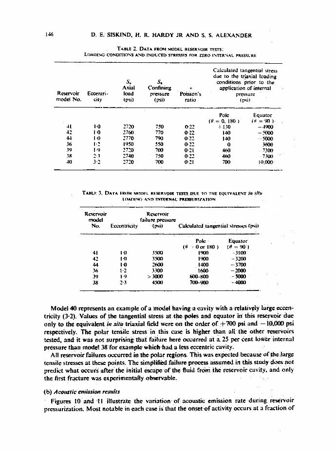
A total of twelve of the type-2 reservoirs were fabricated using the method described earlier, and of these, seven were successfully tested. Table 2 lists the loading conditions, reservoir geometries and reservoir failure pressures. Four of the models contained essenti- ally spherical reservoirs, and the remaining three had elliptically shaped cavities (spheroids). Most notable were the high values of the reservoir pressures at failure. Also listed in Table 2 are the theoretical applied tangential stresses at the poles and equators of the model reservoirs due to the equivalent in situ loading (based on the curves of Figs 2, 3, 5 and 6).
The total tangential stress at the poles and the equator of the reservoir models at failure due to the equivalent in situ loading and the internal pressures are given in Table 3 (based on Figs 2, 3, 5 and 6, equation (14), and the finite-element data obtained for pressurized elliptical cavities from HARDY and CtlUGI! [13]).
The data presented indicates that the reservoir cavities had high values of tensile stress at the poles at the time of failure. The four spherical reservoirs (41, 42, 44, 36) had approxi- mately the same stress, average of the order of 1700 psi, which is significantly greater than the material tensile strength of 400-500 psi. The models containing spheroidal cavities (38 and 39) had lower tensile stresses at the poles and higher values of compressive stress at the equator with failure by tension at the poles still expected.
146 D. E. SISKIND, H. R. HARDY JR AND S. S. ALEXANDER
TABLE 2. DATA FROM MODEL RESERVOIR I'ESTS: LOADI?',G CONDITIONS AND INDUCED STRESSES FOR ZERO INTERNAL PRESSURE
Reservoir model No,
Calculated tangential stress due to the triaxial loading
S~ S~ conditions prior to the Axial Confining v appl icat ion of internal
Eccentri- load pressure Poisson's pressure city (psi) (psi) ratio (psi
Pole Equator ( 0 = 0 , 1 8 0 ) (0 = 9 0 )
41 I'0 2720 750 0"22 - 130 4900 42 1-0 2760 770 0"22 140 5000 44 1.0 2770 790 0.22 140 - - 5000 36 I "2 1950 550 0-22 0 - 3600 39 1.9 2720 700 0"21 460 - 7300 38 2'3 2740 750 0-22 460 7300 40 3" 2 2720 700 O- 21 700 I 0,000
TABLE 3. DATA FROM MODEL RESERVOIR TESTS DUE TO r i lE EQUIVALENT i l l . ' i#li LOADING AND INTERNAL PRE~tSURIZATION
Reservoir Rc.'scrvoir model failure pressure
No. Eccentricity (psi) Calculated tangential stresses (psi)
Pole Equator ( 0 - O o r 180 ) (0 = 9 0 )
41 I-0 3500 1900 -3100 4 2 1.0 3 5 0 0 1900 - 3200 44 I -O 2600 1400 -- 3700 36 1.2 3300 1600 -2000 39 1.9 > 3000 600.-800 - 5000 38 2" 3 4500 700-900 - 4000
Model 40 r e p r e s e n t s a n example o f a mode l having a cavi ty with a relat ively large eccen- t r ic i ty (3-2). Values o f the tangent ia l stress a t t he poles and e qua to r in this reservoir d u e only to the equiva len t in situ t r iaxia l field were on the o r d e r o f + 7 0 0 psi and - - IO,000 psi respectively. The po la r tensile stress in this case is h igher than all the o the r reservoirs tested, and i t was no t surpr i s ing t ha t fai lure here occurred a t a 25 per cent lower in te rna l pressure than model 38 for example which had a less eccentric cavi ty.
All reservoir failures occur red in the p o l a r regions. This was expected because o f the large tensile stresses at these points . The s implif ied fai lure process assumed in this s tudy does not p red ic t wha t occurs af ter the initial escape o f the fluid from the reservoi r cavity, and only the first f racture was exper imenta l ly observable .
(b) Acoustic emission results
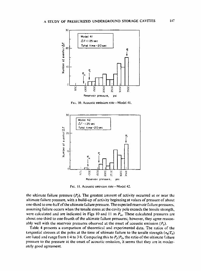
Figures !0 and I I i l lustrate the var ia t ion o f acous t ic emiss ion rate dur ing reservoir pressurizat ion. Mos t no tab le in each case is tha t the onset o f act ivi ty occurs a t a f ract ion o f
A STUDY OF PRESSURIZED UNDERGROUND STORAGE CAVITIES 147
3C
I - -
<3 "*-20
.D I0 E
Z
Model 41
AT= I -25 see
Total t ime - 2 0 sec
m
0
Reservoir pressure, psi
EnG. 10. Acoust ic emission r a t e - - M o d e l 41.
30;
t . -
<3
I 0 E
Z
Model 42 ~T : I. 25 sec
Total t i m e - 2 0 sec
r - - l l I
Reservoir pressure, psi
FtG. I 1. Acoust ic emission r a t e - - M o d e l 42.
the ultimate failure pressure (Ps). The greatest amount of activity occurred at or near the ultimate failure pressure, with a build-up of activity beginning at values of pressure of about one-third to one-half of the ultimate failure pressure. The expected reservoir failure pressures, assuming failure occurs when the tensile stress at the cavity pole exceeds the tensile strength, were calculated and are indicated in Figs 10 and 1 1 as Pt,- These calculated pressures are about one-third to one-fourth of the ultimate failure pressures; however, they agree reason- ably well with the reservoir pressures observed at the onset of acoustic emission (Po).
Table 4 presents a comparison of theoretical and experimental data. The ratios of the tangential stresses at the poles at the time of ultimate failure to the tensile strength (,to/To) are listed and range from 1.4 to 3.8. Comparing this to P.,'/Po, the ratio of the ultimate failure pressure to the pressure at the onset of acoustic emission, it seems that they are in moder- ately good agreement.

148 0. E. SISKIND, H. R. HARDY JR AND S. S. ALEXANDER
Shown in Fig. 12 is a typical acoustic emission event obtained during one of the reservoir model tests. Examination of several sets of such events selected over the complete loading and Failure cycle did not reveal any obvious trends in the characteristics of the events, except For increases in the rates of occurrence as the reservoir approached the Failure point. It is interesting to note that iarge magnitude events appeared to be scattered throughout the test rather than being concentrated near the Failure point as might have been expected.
Little dispersion was Found in the acoustic emission pulses. A constant period of about 20 ~sec seemed to pe rsist as Far down the wave train as could be measured; however, in some of the better photographs, a predominant Frequency of about 56 kHz seemed to characterize the beginning of the pulse. slowly dropping off to about 48 kHz after about 2 t~sec. This was not usually noticeable because of the short duration and rapid decay of the events. It was expected that perhaps there would be a change in dominant Frequency as the Faiture point was approached, but none was Found.
There was a distinctive ringing effect probably caused by reflections within the loading ram and the specimen. The durations of the main pulses were about 200 @ec but the ringing resulting From the multipath arrivals continued For several milliseconds. The basic envelopes of the pulses were typical exponential decay curves observed in most acoustic emission studies.
7. CONCIAJSIONS
The objective of this study was the examination of the faiture characteristics of internally prcssurizcd cavities subjected to triaxial it1 situ stress fields. The experimental resutts indicate the Following primary conclusions:
(I) The onset of acoustic emission activity is a sign of the beginning oF reservoir instability with :m increasing rate of events indicative of continuing and increasing instability. In the present study, the onset of such activity in each model~rescrvoir approximatcty coincided with the point at which the tensite stress at the cavity wall in the polar region exceeded the tensile strength of the model materiat. These results are summarized in Table 4.
TAULE 4. RESERVOIR STRESSES AND ACOUSTIC MSSAON DATA
PO
Tan&tiul Reservoir
Pf pressure at stress at Rgswvoir onset
failure (psi) prssure at mierwcismif Model No. (8 = 0, IW) dTl”” ftilure ipsi) iwtivity (psi) P,lPu
41 I’)(x) 3-n 3soo 1200 2.9 42 1900 3.8 3500 1608 2.2 44 1400 2-8 2600 1200 2.2 36 1600 3.2 3u10 WI0 2-3 38 ?OO+OO Id-I-8 4500 3700 I$!
l To is the tcnde strength of the model material.

FI(;. 12. Typical acoustic emission pulses---Model 42.
RM f.p. 14gl

A STUDY OF PRESSURIZED UNDERGROUND STORAGE CAVITIES 149
(2) The most critical reservoir parameters were found to be the values of the tensile strength and Poisson's ratio of the rock surrounding the cavity.
(3) The results obtained could be applied to some full-scale reservoir cavities of regular geometry; however, extreme eccentricities, angular cavities, a predominance of preexisting fractures and inelastic behavior present in many cases must be taken into account.
(4) The analyses presented are based on the assumption that the internally pressurized cavities are empty or devoid of solid material. As already discussed, real storage reservoirs are usually filled with material which is relatively porous but capable of transmitting stress. It is probable that the stress concentrations caused by loading such filled reservoir cavities would not be as high as those found in the present study, due to the support provided by this porous rock. Problems of this complexity are best attacked analytically using finite-element techniques.
(5) The primary results of this study are the predicted polar locations of the cavity failures and the unusually high failure pressures possible in such cavities. For example, at ultimate failure the model reservoirs tested had values of tangential stresses in the polar regions in the range of 2.8-3.8 times the tensile strength.
(6) There exist a number of logical extensions of the present work in the areas of model and field studies. Stresses could be directly measured in models ktrge enough to have internally mounted strain gages. The instrumentation of a full-scale reservoir for seismic detection would be of considerable value in addition to the extension of the analytical techniques presented to related geological problems such as the intrusion of laccoliths, etc.
,.h'knowh,dements-The research described was supported by funds supplied by the Pipeline Research Committee of the American Gas Association as part of a continuing project (PR-12-431 with the Department of Mineral Engineering at The Pennsylvania State University.
The majority of the material presented in this paper forms part of a Ph.D. Thesis in Geophysics at the Pennsylvania State University by one of the attthors (Siskindl.
REFERENCES
I. Emu)N J. F. Herscher: First use of water sand for natural gas storage. Gas, Los Angeh,s 31, I07-115 (1955).
2. Oaeur L. and DUVALL W. I. Rock Mechanics and the Desicn of Slrnclure$ in Rock, Wiley, New York (1967).
3. CRANDALL F. J. Determination of incident roof failures in rock tunnels by micro-seismic detection. J. Boston Soc. cir. Engrs 39-59, January (1955).
4. OLIVER J., RYALL A. and BRUNE J. N. Microearthquake activity recorded by portable seismographs o f high sensitivity. Bull. seism. Soc. Am. 56, 899-924 0966).
5. GOODMan R. Subaudible noise during compression of rock. Bull. geol. Soc. Am. 74, 487-490 (1963). 6. SCHOLZ C. H. Microfracturing and the inelastic deformation of rocks in compression. J. geoph.vs. Res.
73, 1417-1432 (1968). 7. HARDY H. R. JR, KIM R. Y., SrEFANKO R. and WANG Y. J. Creep and Microseismic Activity in Geologic
Materials, Proceedin, es o f the Eleventh Symposium on Rock Mechanics, Berkeley, 1969, pp. 377-413, AIME, New York (1970).
8. SCHOLZ C. H. Experimental study of the fracturing process in brittle rock. J. geophys. Res. 73, 1447-1452 (1968).
9. CHUG8 Y. P., HARDY H. R. Jr and SrEEANKO R. Recent laboratory studies o f microseismic activity in rock under stress [abstract only]. Trans. Am. geophys. Un. 49, 300 (1968).
10. KNILL J. L., FRANKUN J. A. and MALONE A. W. A study of acoustic emission from stressed rock. hit. J. Rock Mech. Min. SoL 5, 87-121.
I I. SAOOWSKY M. A. and Srersm!rG E. Stress concentration around a triaxial ellipsoidal cavity. J. appl. ,Vh, ch. 71, 149-157 (1949).
ROCK 1012--~
150 D. E. SISKIND, H. R. HARDY JR AND S. S. ALEXANDER
I~ Tr~zAOH! IC and RICHART F. E. Ja Stresses in rock around cavities. Geot~c /m~ 3, 57-90 (1952). 13. HAaDY H. R, Jr and CHUGH Y' P. Application o f the Finite Element Analysi~ Teehniq~w to the Incestiga-
tion o f Stresses around Underground Gas Storage Reservoirs, Research ProlF¢~ Report AGA/69't, Department of M ~ E n g i ~ g , The Pennsylvania State University (1969).
14. McNivr~ H. D. and EwolJ3~N H, M. Rockboitingof tunnels for structural support: Int. J. Rock Mech, Min. Sci. 6, 465-481 (1969).
15. P e ~ J. Applied Elasticity, Dover, New York (1946). 16. TIMOSHENKO S. and GOODIEa J. M, Theory o f Elasticity, McGraw-Hill, New York (1951). i 7. RO~mLAD J. L. Development of a Rock-like Material, Proceedings o f the Tenth Symposium on Rock
Mechanics, Austin, Texas 1968, AAME, New York (1972). 18. HARDY H. R. JR' KIMaeL E. and KIM R. Y. Development of facilities for monitoring microseismic
activity in geologic materials [Abstract only]. Trans, Am. geophys. Un. $1, 350 (|970).:
Related Documents