1 Protecting Military Avionics Platforms from Attacks on MIL-STD-1553 Communication Bus Orly Stan, Yuval Elovici, Asaf Shabtai, Gaby Shugol, Raz Tikochinski, Shachar Kur Abstract—MIL-STD-1553 is a military standard that defines the physical and logical layers, and a command/response time division multiplexing of a communication bus used in military and aerospace avionic platforms for more than 40 years. As a legacy platform, MIL-STD-1553 was designed for high level of fault tolerance while less attention was taken with regard to security. Recent studies already addressed the impact of successful cyber attacks on aerospace vehicles that are implementing MIL-STD-1553. In this study we present a security analysis of MIL-STD-1553. In addition, we present a method for anomaly detection in MIL-STD-1553 communication bus and its performance in the presence of several attack scenarios implemented in a testbed, as well as results on real system data. Moreover, we propose a general approach towards an intrusion detection system (IDS) for a MIL-STD-1553 communication bus. Index Terms—MIL-STD-1553, anomaly detection, communication bus security. ✦ 1 I NTRODUCTION M IL-STD-1553 is a military standard developed by the US Department of Defense (DoD) for the purpose of military platform integration [6] which has served as the backbone of military and aerospace avionic platforms (e.g., F-15, AH-64 Apache, F-16, V-22, X-45A, F-35) for more than 40 years. It is primarily used for mission-critical systems that require a high level of fault tolerance, since it is deterministic and dual redundant; it also uses a reduced cable topology, connecting all devices on a single bus in a multipoint topology, as opposed to point-to-point topologies. MIL-STD-1553 is considered deterministic, because it is based on a master/slave methodology in which the master issues messages based on a predefined order and timing. Although other modern, reliable and deterministic data buses have been introduced [5], [8], MIL-STD-1553 remains the most widely used standard in military aviation as it has been for the last 40 years, and is expected to be used in the future. The main reason that alternative deterministic communication buses are not used in existing platforms is the difficulty of modifying an entire operational platform and replacing the main data transmission topology. More- over, subsequent standards are based on the communication protocol defined by MIL-STD-1553. For these reasons, MIL- STD-1553 will likely be an integral component of critical military platforms for many more years to come. MIL-STD-1553 was developed long before the notion of cyber security was familiar and even basic cyber attacks, such as denial-of-service (DoS) attacks [9], had not yet been introduced. Research regarding DoS attacks initially reported in the early 1980s, several years after the release of the most recent version of MIL-STD-1553 in 1978, and • O. Stan, Y. Elovici, and A. Shabtai are with the Department of Software and Information Systems Engineering, Ben-Gurion University of the Negev. E-mails: [email protected], {elovici,shabtaia}@bgu.ac.il • G. Shugol, R. Tikochinski, and S. Kur are with Astronautics C.A. ltd. E-mails: {g.shugol, r.tikochinski, s.kur}@astro.co.il focused mainly on DoS in operating systems, rather than computer networks [9]. The Designer’s Notes for MIL- STD-1553 include a chapter discussing several aspects of network system security which should be addressed when implementing a 1553 communication bus [6]: • system security policy – defines the classification levels of the system, data, and personnel that are related to the communication bus; • system security architecture – specifies four approaches for designing systems that process classified plain text data and unclassified data; • Tempest – states that all components processing un- encrypted classified data should be protected against compromising emanation; • Encryption – should be used in order to isolate compo- nents with different classification levels from classified data; • Trusted message routing and control design – maintain- ing low bit error rate, parity coding of control words, and monitoring the bus controller can help in detecting errors in messages or in their routing. Although the Designer’s Notes provide references to security aspects, they only contain general guidelines, in- cluding references to standards that might not be appro- priate for all MIL-STD-1553-based systems (e.g., military vessels developed by other countries might have different or additional compliance requirements than those defined in MIL-STD-1553). Moreover, because the standard is defined for military purposes, more specific guidelines cannot be provided due to confidentiality requirements. Finally, the standard is implemented by various types of systems with diverse objectives, which makes it extremely complicated to provide more specific requirements will suite all existing systems. Therefore, despite the attention paid to security issues in the Designer’s Notes, MIL-STD-1553 still contains vulnera- bilities that expose the platforms implementing it to cyber attacks, which are not addressed in the Designer’s Notes or in the various updates that have been made to the standard arXiv:1707.05032v1 [cs.CR] 17 Jul 2017

Welcome message from author
This document is posted to help you gain knowledge. Please leave a comment to let me know what you think about it! Share it to your friends and learn new things together.
Transcript
1
Protecting Military Avionics Platforms fromAttacks on MIL-STD-1553 Communication Bus
Orly Stan, Yuval Elovici, Asaf Shabtai, Gaby Shugol, Raz Tikochinski, Shachar Kur
Abstract—MIL-STD-1553 is a military standard that defines the physical and logical layers, and a command/response time divisionmultiplexing of a communication bus used in military and aerospace avionic platforms for more than 40 years. As a legacy platform,MIL-STD-1553 was designed for high level of fault tolerance while less attention was taken with regard to security. Recent studiesalready addressed the impact of successful cyber attacks on aerospace vehicles that are implementing MIL-STD-1553. In this study wepresent a security analysis of MIL-STD-1553. In addition, we present a method for anomaly detection in MIL-STD-1553 communicationbus and its performance in the presence of several attack scenarios implemented in a testbed, as well as results on real system data.Moreover, we propose a general approach towards an intrusion detection system (IDS) for a MIL-STD-1553 communication bus.
Index Terms—MIL-STD-1553, anomaly detection, communication bus security.
F
1 INTRODUCTION
M IL-STD-1553 is a military standard developed by theUS Department of Defense (DoD) for the purpose of
military platform integration [6] which has served as thebackbone of military and aerospace avionic platforms (e.g.,F-15, AH-64 Apache, F-16, V-22, X-45A, F-35) for more than40 years. It is primarily used for mission-critical systems thatrequire a high level of fault tolerance, since it is deterministicand dual redundant; it also uses a reduced cable topology,connecting all devices on a single bus in a multipointtopology, as opposed to point-to-point topologies.
MIL-STD-1553 is considered deterministic, because it isbased on a master/slave methodology in which the masterissues messages based on a predefined order and timing.Although other modern, reliable and deterministic databuses have been introduced [5], [8], MIL-STD-1553 remainsthe most widely used standard in military aviation as it hasbeen for the last 40 years, and is expected to be used inthe future. The main reason that alternative deterministiccommunication buses are not used in existing platforms isthe difficulty of modifying an entire operational platformand replacing the main data transmission topology. More-over, subsequent standards are based on the communicationprotocol defined by MIL-STD-1553. For these reasons, MIL-STD-1553 will likely be an integral component of criticalmilitary platforms for many more years to come.
MIL-STD-1553 was developed long before the notion ofcyber security was familiar and even basic cyber attacks,such as denial-of-service (DoS) attacks [9], had not yetbeen introduced. Research regarding DoS attacks initiallyreported in the early 1980s, several years after the releaseof the most recent version of MIL-STD-1553 in 1978, and
• O. Stan, Y. Elovici, and A. Shabtai are with the Department of Softwareand Information Systems Engineering, Ben-Gurion University of theNegev.E-mails: [email protected], {elovici,shabtaia}@bgu.ac.il
• G. Shugol, R. Tikochinski, and S. Kur are with Astronautics C.A. ltd.E-mails: {g.shugol, r.tikochinski, s.kur}@astro.co.il
focused mainly on DoS in operating systems, rather thancomputer networks [9]. The Designer’s Notes for MIL-STD-1553 include a chapter discussing several aspects ofnetwork system security which should be addressed whenimplementing a 1553 communication bus [6]:• system security policy – defines the classification levels
of the system, data, and personnel that are related tothe communication bus;
• system security architecture – specifies four approachesfor designing systems that process classified plain textdata and unclassified data;
• Tempest – states that all components processing un-encrypted classified data should be protected againstcompromising emanation;
• Encryption – should be used in order to isolate compo-nents with different classification levels from classifieddata;
• Trusted message routing and control design – maintain-ing low bit error rate, parity coding of control words,and monitoring the bus controller can help in detectingerrors in messages or in their routing.
Although the Designer’s Notes provide references tosecurity aspects, they only contain general guidelines, in-cluding references to standards that might not be appro-priate for all MIL-STD-1553-based systems (e.g., militaryvessels developed by other countries might have differentor additional compliance requirements than those defined inMIL-STD-1553). Moreover, because the standard is definedfor military purposes, more specific guidelines cannot beprovided due to confidentiality requirements. Finally, thestandard is implemented by various types of systems withdiverse objectives, which makes it extremely complicatedto provide more specific requirements will suite all existingsystems.
Therefore, despite the attention paid to security issues inthe Designer’s Notes, MIL-STD-1553 still contains vulnera-bilities that expose the platforms implementing it to cyberattacks, which are not addressed in the Designer’s Notes orin the various updates that have been made to the standard
arX
iv:1
707.
0503
2v1
[cs
.CR
] 1
7 Ju
l 201
7
2
since its first release. Section 4 provides a security analysisof MIL-STD-1553 and discusses possible attack methods andtheir consequences.
As cyber attacks play a major role in modern warfare andsince military platforms are likely to be attractive targets forattackers [20], [16] , it has become clear that the systems im-plementing the MIL-STD-1553 standard require improvedprotection. Due to its widespread deployment in many plat-forms, applying changes to the various components of the1553 communication bus is cost prohibitive. Hence, insteadof securing the standard itself, we introduce a method forthe detection of anomalous traffic transmitted over the 1553communication bus.
Recent studies have addressed the impact of successfulcyber-attacks on aerospace vehicles that implement MIL-STD-1553 [19], [24]. In [24] the author presents some of theassociated vulnerabilities and suggests theoretical methodsfor creating covert channels over the communication bus.The authors in [19] illustrated the physical impact of simu-lated cyber-attack on an aerospace vehicle. However, noneof them proposed a solution for detect and/or prevent suchattacks.
In this paper we present a security analysis of the MIL-STD-1553 communication protocol and propose a super-vised sequence-based anomaly detection method for iden-tifying cyber-attacks. For evaluating our method we estab-lished an operational testbed in which we executed threeattack scenarios. All three attacks were perfectly identifiedby our proposed method. Moreover we evaluated the learn-ing process of the proposed method on datasets collectedfrom a real system; this evaluation indicates that a veryshort period of time (two to five seconds) is sufficient forachieving a very low false alarm rate.
The following sections provide: an overview of the MIL-STD-1553 architecture and communication protocol (Section2); a review of related works regarding the security ofsystems implementing MIL-STD-1553 and other commu-nication bus technologies, (Section 3); a security analysiswhich defines the assets of a MIL-STD-1553 bus, the attackerprofile, and possible threats to the communication bus (Sec-tion 4); proposal for a sequence-based anomaly detectionmethod for a MIL-STD-1553 communication bus (Section 5);description of the testbed established for evaluating the pro-posed method and evaluation results for both simulated andreal-system scenarios (Section 6); finally Section 7 discussesthe performance and limitations of the proposed sequence-base anomaly detection method and suggests extensions tothe method; Section 8 concludes the paper and presentsfuture research direction.
2 1553 COMMUNICATION BUS - BACKGROUND
MIL-STD-1553 defines a dual redundant serial communica-tion bus used for transmitting data between a bus controllerand remote terminals using a multipoint, master-slave bustopology. It was first published in 1973 and the latest ver-sion, MIL-STD-1553B, published in 1978, is still used inmany military and aerospace systems to this day. MIL-STD-1553 defines the physical layer of the communication busas well as the logical layer and a command/response timedivision multiplexing methodology using a 1Mbps transferrate data bus, while specifying the transmission timings.
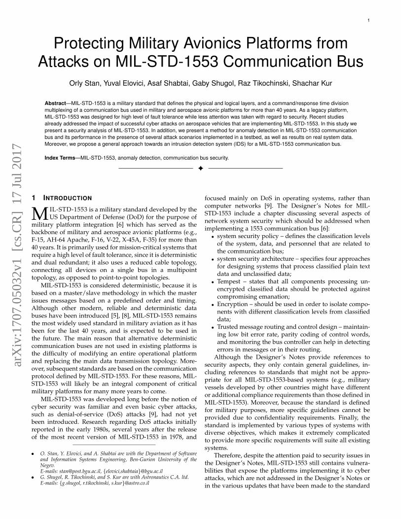
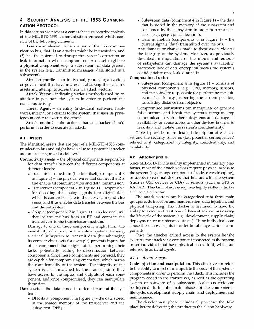
Fig. 1. The MIL-STD-1553 bus architecture and its primary components.
2.1 Bus architecture
The 1553 communication bus includes five key elements:Remote terminal (RT), bus controller (BC), bus monitor(BM), coupler, and the bus itself (illustrated in Figure 1).The bus is redundant – if a message cannot be transmittedon the main channel it will be retransmitted on the backupchannel. Although there are redundant channels, only oneelement can transmit data over the bus at a time. Allelements connected to the bus are continuously exposedto the data transmitted, even if not designated for them.The communication is managed by the BC, and all otherelements follow its commands. The bus can support up to31 connected remote terminals.
Remote terminal (RT). Consists of three components.The hardware transceiver is responsible for data transferbetween the bus and the subsystem. It is connected directlyto the bus and exchanges data with the subsystem via a dualport RAM (DPR). In addition, it must be able to decode andbuffer messages, detect transmission errors, and performdata validation tests. Invalid data should be discarded. TheDPR is shared memory which enables data transfer betweenthe transceiver and the subsystem. Both the transceiverand subsystem have read and write permission to thismemory. The subsystem is the computational unit (platformcomputer) of the RT. The subsystem is responsible for alldata processing and calculations required for the system tofunction.
Bus controller (BC). Responsible for managing the com-munication between the RTs connected to the bus usingcommand/response messages. It is the only component thatinitiates data transfers on the bus to/from RTs or betweentwo RTs. There may be several terminals with BC capabili-ties connected to the same bus for backup, but only one ofthem can function as the active BC at a given time. The BCinitiates commands to the RTs based on a predefined orderand timing.
Bus monitor (BM). Responsible for listening and col-lecting data from the bus in order to observe the stateand operational mode of the system and subsystems. TheBM is a passive device and does not send any messages,and therefore cannot provide a status report on the datatransferred over the bus.
Coupler. A physical component used to isolate thecomponents connected to the bus from one another andeliminate the possibility of damage to the bus in case oneof the components malfunctions.
3
Data Bus. The transmission medium that physicallyenables all communication between the components con-nected to it.
2.2 Communication protocolWords are the data structure used for transmitting com-mands, data, and status over the bus. A collection of wordsdefines a message used for receiving or transmitting data.Messages can be periodic or aperiodic. Periodic messagesare sent at fixed time intervals (i.e., time cycles). A majorframe is a predefined time frame in which all periodicmessages are transmitted at least once (derived from theperiodic message with the longest time cycle). Aperiodicmessages are event-driven and therefore are not sent infixed time cycles. However, they have a fixed time slot inthe major frame.
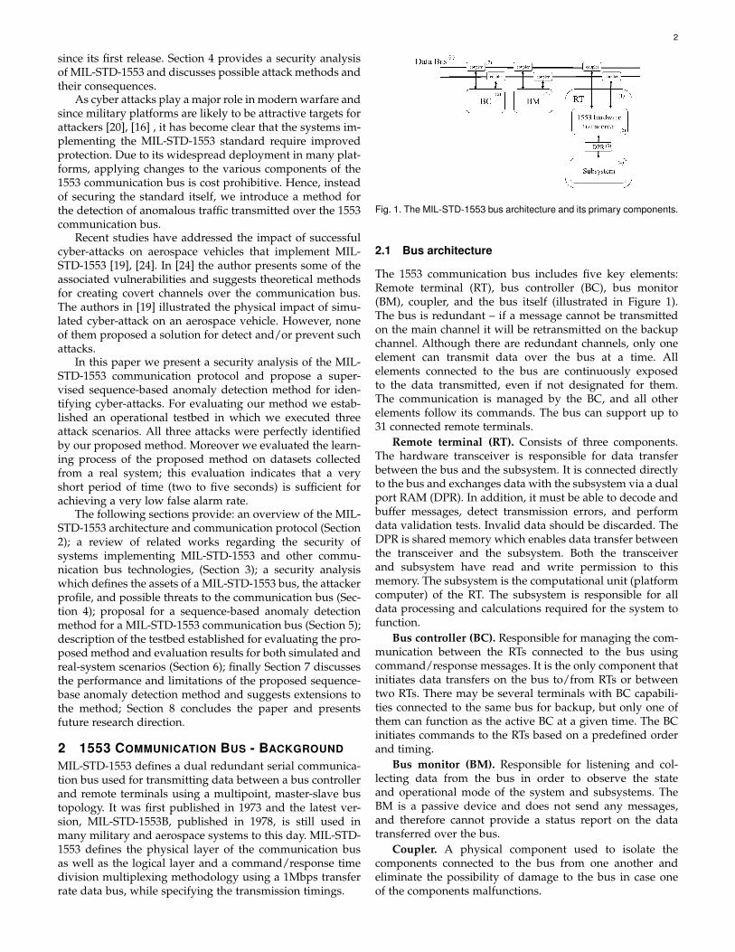
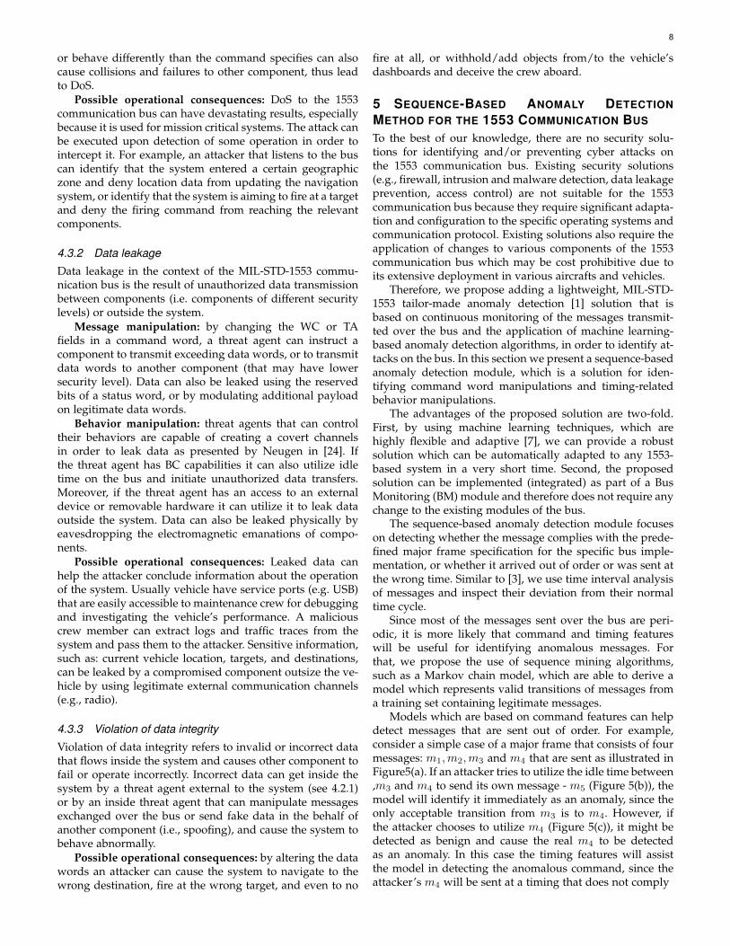
The standard defines three types of words: command,data, and status (illustrated in Figure 2). All words are 20bits long, starting with three bits of synchronization andending with a parity bit.Command word. Initiated by the BC and designated to
an RT. The command specifies the action that the RTshould perform: whether to receive or transmit data.The remaining 16 bits are defined as follows:Terminal address (TA) – a five bit field containing theaddress of the RT that the command is designatedfor. It can contain up to 31 RT addresses (00000B to11110B), since the terminal address 11111B is reservedfor broadcast command.T/R bit – a single bit that indicates the direction of therequired data transfer. Logic 1 indicates that the RTshould transmit data, and logic 0 indicates that the RTshould receive data.Subaddress/Mode – a five bit field indicating the subad-dress of the RT to receive/transmit the data, or thatthis command is a mode code (in this case it is set to00000B or 11111B). Mode codes are special commandsused to change the operation mode of the RTs such as:timing synchronization, RT transmitter shut down, andrequest to initiate self-test.Data word count/mode code – a five bit field whichcontains the number of data words to be re-ceived/transmitted. If a mode code is set, these five bitsindicate the mode code.
Data word. Contains the actual data being transferred onthe bus. There is no predefined structure for data words.
Status word. Sent by the RT to the BC upon receiving avalid message, in order to report its status to the BC.It contains different flags indicating different types oferrors, such as received data error, data processingerror, and circuitry error. It also allows the RT to requesta service from the BC.
2.3 Communication formatsThere are four types of communication between elementsover the bus, all of which are initiated by the BC. The com-munication formats are designed to maintain high reliabilityof the protocol by acknowledging every message sent on thebus and flagging for errors and validation of the messages(using status words).
Fig. 2. Communication protocol words structure.
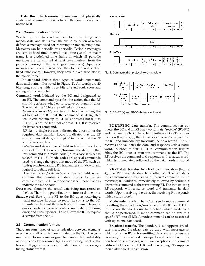
Fig. 3. BC-RT (a) and RT-BC (b) transfer format.
BC-RT/RT-BC data transfer. The communication be-tween the BC and an RT has two formats: ’receive’ (BC-RT)and ’transmit’ (RT-BC). In order to initiate a BC-RT commu-nication (Figure 3(a)), the BC issues a ’receive’ command tothe RT, and immediately transmits the data words. The RTreceives and validates the data, and responds with a statusword. In order to start a RT-BC communication (Figure3(b)), the BC issues a ’transmit’ command to the RT. TheRT receives the command and responds with a status word,which is immediately followed by the data words it shouldtransmit.
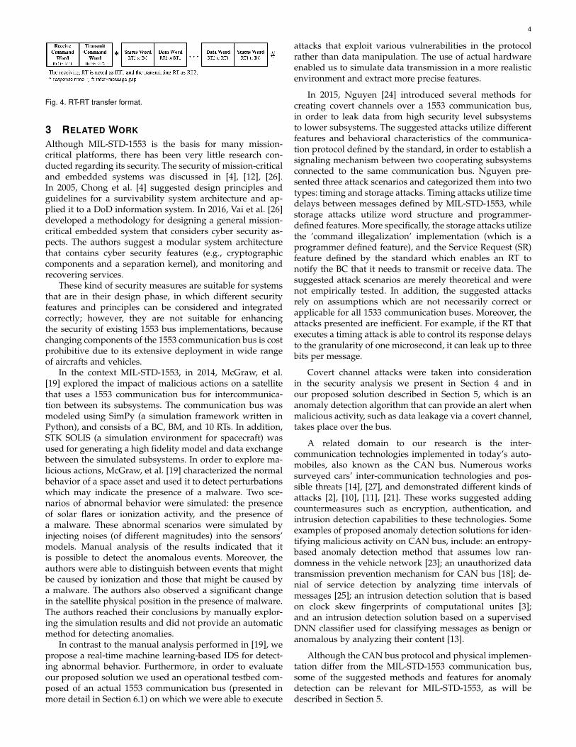
RT-RT data transfer. In RT-RT communication (Figure4), one RT transmits data to another RT. The BC startsthe communication by issuing a ’receive’ command to thereceiving RT, which is immediately followed by sending a’transmit’ command to the transmitting RT. The transmittingRT responds with a status word and transmits its datawords. Upon receiving the data, the receiving RT respondswith a status word.
Mode code transfer. The BC can send a mode commandby setting the subaddress/mode field to 00000B or 11111B.In this case the word count field defines which mode codeshould be performed. A mode command can be sent to aspecific RT or to all RTs. A mode command can be associatedwith up to one data word.
Broadcast transfer. The standard also supports broad-cast messages. Broadcast can be used with messages inwhich only the BC is transmitting data and all others arereceiving. The broadcast message format is similar to thenon-broadcast messages, with two exceptions: the terminaladdress field is set to 11111B, and all receiving RTs suppresstheir status word transmission.
4
Fig. 4. RT-RT transfer format.
3 RELATED WORK
Although MIL-STD-1553 is the basis for many mission-critical platforms, there has been very little research con-ducted regarding its security. The security of mission-criticaland embedded systems was discussed in [4], [12], [26].In 2005, Chong et al. [4] suggested design principles andguidelines for a survivability system architecture and ap-plied it to a DoD information system. In 2016, Vai et al. [26]developed a methodology for designing a general mission-critical embedded system that considers cyber security as-pects. The authors suggest a modular system architecturethat contains cyber security features (e.g., cryptographiccomponents and a separation kernel), and monitoring andrecovering services.
These kind of security measures are suitable for systemsthat are in their design phase, in which different securityfeatures and principles can be considered and integratedcorrectly; however, they are not suitable for enhancingthe security of existing 1553 bus implementations, becausechanging components of the 1553 communication bus is costprohibitive due to its extensive deployment in wide rangeof aircrafts and vehicles.
In the context MIL-STD-1553, in 2014, McGraw, et al.[19] explored the impact of malicious actions on a satellitethat uses a 1553 communication bus for intercommunica-tion between its subsystems. The communication bus wasmodeled using SimPy (a simulation framework written inPython), and consists of a BC, BM, and 10 RTs. In addition,STK SOLIS (a simulation environment for spacecraft) wasused for generating a high fidelity model and data exchangebetween the simulated subsystems. In order to explore ma-licious actions, McGraw, et al. [19] characterized the normalbehavior of a space asset and used it to detect perturbationswhich may indicate the presence of a malware. Two sce-narios of abnormal behavior were simulated: the presenceof solar flares or ionization activity, and the presence ofa malware. These abnormal scenarios were simulated byinjecting noises (of different magnitudes) into the sensors’models. Manual analysis of the results indicated that itis possible to detect the anomalous events. Moreover, theauthors were able to distinguish between events that mightbe caused by ionization and those that might be caused bya malware. The authors also observed a significant changein the satellite physical position in the presence of malware.The authors reached their conclusions by manually explor-ing the simulation results and did not provide an automaticmethod for detecting anomalies.
In contrast to the manual analysis performed in [19], wepropose a real-time machine learning-based IDS for detect-ing abnormal behavior. Furthermore, in order to evaluateour proposed solution we used an operational testbed com-posed of an actual 1553 communication bus (presented inmore detail in Section 6.1) on which we were able to execute
attacks that exploit various vulnerabilities in the protocolrather than data manipulation. The use of actual hardwareenabled us to simulate data transmission in a more realisticenvironment and extract more precise features.
In 2015, Nguyen [24] introduced several methods forcreating covert channels over a 1553 communication bus,in order to leak data from high security level subsystemsto lower subsystems. The suggested attacks utilize differentfeatures and behavioral characteristics of the communica-tion protocol defined by the standard, in order to establish asignaling mechanism between two cooperating subsystemsconnected to the same communication bus. Nguyen pre-sented three attack scenarios and categorized them into twotypes: timing and storage attacks. Timing attacks utilize timedelays between messages defined by MIL-STD-1553, whilestorage attacks utilize word structure and programmer-defined features. More specifically, the storage attacks utilizethe ’command illegalization’ implementation (which is aprogrammer defined feature), and the Service Request (SR)feature defined by the standard which enables an RT tonotify the BC that it needs to transmit or receive data. Thesuggested attack scenarios are merely theoretical and werenot empirically tested. In addition, the suggested attacksrely on assumptions which are not necessarily correct orapplicable for all 1533 communication buses. Moreover, theattacks presented are inefficient. For example, if the RT thatexecutes a timing attack is able to control its response delaysto the granularity of one microsecond, it can leak up to threebits per message.
Covert channel attacks were taken into considerationin the security analysis we present in Section 4 and inour proposed solution described in Section 5, which is ananomaly detection algorithm that can provide an alert whenmalicious activity, such as data leakage via a covert channel,takes place over the bus.
A related domain to our research is the inter-communication technologies implemented in today’s auto-mobiles, also known as the CAN bus. Numerous workssurveyed cars’ inter-communication technologies and pos-sible threats [14], [27], and demonstrated different kinds ofattacks [2], [10], [11], [21]. These works suggested addingcountermeasures such as encryption, authentication, andintrusion detection capabilities to these technologies. Someexamples of proposed anomaly detection solutions for iden-tifying malicious activity on CAN bus, include: an entropy-based anomaly detection method that assumes low ran-domness in the vehicle network [23]; an unauthorized datatransmission prevention mechanism for CAN bus [18]; de-nial of service detection by analyzing time intervals ofmessages [25]; an intrusion detection solution that is basedon clock skew fingerprints of computational unites [3];and an intrusion detection solution based on a supervisedDNN classifier used for classifying messages as benign oranomalous by analyzing their content [13].
Although the CAN bus protocol and physical implemen-tation differ from the MIL-STD-1553 communication bus,some of the suggested methods and features for anomalydetection can be relevant for MIL-STD-1553, as will bedescribed in Section 5.
5
4 SECURITY ANALYSIS OF THE 1553 COMMUNI-CATION PROTOCOL
In this section we present a comprehensive security analysisof the MIL-STD-1553 communication protocol which con-sists of the following elements:
Assets – an element, which is part of the 1553 commu-nication bus, that (1) an attacker might be interested in, and(2) has the potential to disrupt the system’s operation orleak information when compromised. An asset might bea physical component (e.g., a subsystem), or data presentin the system (e.g., transmitted messages, data stored in asubsystem).
Attacker profile – an individual, group, organization,or government that have interest in attacking the system’sassets and attempt to access them via attack vectors.
Attack Vector – indicating various methods used by anattacker to penetrate the system in order to perform themalicious activity.
Threat Agent – an entity (individual, software, hard-ware), internal or external to the system, that uses its privi-leges in order to execute the attack.
Attack method – the actions that an attacker shouldperform in order to execute an attack.
4.1 AssetsThe identified assets that are part of a MIL-STD-1553 com-munication bus and might have value to a potential attackerare can be categorized as follows:Connectivity assets – the physical components responsible
for data transfer between the different components atdifferent levels:• Transmission medium (the bus itself) (component 8
in Figure 1) – the physical wires that connect the RTsand enable all communication and data transmission.
• Transceiver (component 2 in Figure 1) – responsiblefor decoding the analog signals into digital datawhich is comprehensible to the subsystem (and viceversa) and thus enables data transfer between the busand the subsystem.
• Coupler (component 7 in Figure 1) – an electrical unitthat isolates the bus from an RT and connects thetransceivers to the transmission medium.
Damage to one of these components might harm theavailability of a part, or the entire, system. Denyinga critical subsystem to transmit data (by sabotagingits connectivity assets for example) prevents inputs forother component that might fail in performing theirtasks, potentially leading to disconnection betweencomponents. Since these components are physical, theyare capable for compromising emanation, which harmsthe confidentiality of the system. The integrity of thesystem is also threatened by these assets, since theyhave access to the inputs and outputs of each com-ponent, and once compromised, they can manipulatethese data.
Data assets – the data stored in different parts of the sys-tem:• DPR data (component 3 in Figure 1) – the data stored
in the shared memory of the transceiver and thesubsystem (DPR).
• Subsystem data (component 4 in Figure 1) – the datathat is stored in the memory of the subsystem andconsumed by the subsystem in order to perform itstasks (e.g., geographical location).
• Data in motion (components 8 in Figure 1) – thecurrent signals (data) transmitted over the bus.
Any damage or changes made to these assets violatesthe integrity of the system. Moreover, as previouslydescribed, manipulation of the inputs and outputsof subsystems can damage the system’s availability.Moreover, lack of data encryption breaks the system’sconfidentiality once leaked outside.
Computational units:• Subsystem (component 4 in Figure 1) – consists of
physical components (e.g., CPU, memory, sensors)and the software responsible for performing the sub-system’s tasks (e.g., reporting the current position,calculating distance from objects).
Compromised subsystems can manipulate or generatefalse outputs and break the system’s integrity, stopcommunication with other subsystems and damage itsavailability, or abuse access to other devices in order toleak data and violate the system’s confidentiality.
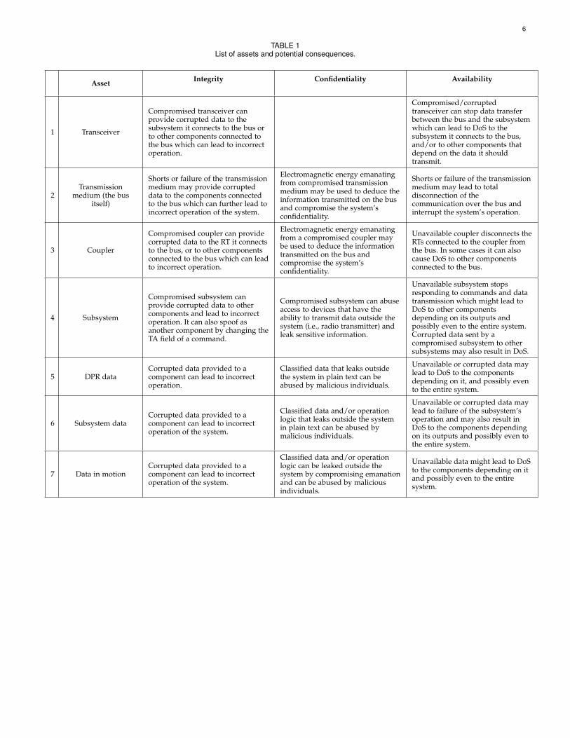
Table 1 provides more detailed description of each as-set and the security concerns (i.e., potential consequences)related to it, categorized by integrity, confidentiality, andavailability.
4.2 Attacker profileSince MIL-STD-1553 is mainly implemented in military plat-forms, most of the attack vectors require physical access tothe system (e.g., change components’ code, eavesdropping),or access to external devices that interact with the system(such as USB devices or CDs) or sensors (such as GPS orRADAR). This kind of access requires highly skilled attackersuch as a state actor.
The attack vectors can be categorized into three maingroups: code injection and manipulation, data injection, andphysical tampering. The attacker is assumed to have theability to execute at least one of these attack vectors duringthe life cycle of the system (e.g., development, supply chain,deployment, or maintenance stages). These individuals canabuse their access rights in order to sabotage various com-ponents.
Once the attacker gained access to the system he/sheexecutes the attack via a component connected to the systemor an individual that have physical access to it, which arereferred to as threat agents.
4.2.1 Attack vectorsCode injection and manipulation. This attack vector refersto the ability to inject or manipulate the code of the system’scomponents in order to perform the attack. This includes theprogram coded in the transceiver, as well as the operatingsystem or software of a subsystem. Malicious code canbe injected during the main phases of the component’slife cycle: development, supply chain, and deployment andmaintenance.
The development phase includes all processes that takeplace before delivering the product to the client: hardware
6
TABLE 1List of assets and potential consequences.
Asset Integrity Confidentiality Availability
1 Transceiver
Compromised transceiver canprovide corrupted data to thesubsystem it connects to the bus orto other components connected tothe bus which can lead to incorrectoperation.
Compromised/corruptedtransceiver can stop data transferbetween the bus and the subsystemwhich can lead to DoS to thesubsystem it connects to the bus,and/or to other components thatdepend on the data it shouldtransmit.
2Transmission
medium (the busitself)
Shorts or failure of the transmissionmedium may provide corrupteddata to the components connectedto the bus which can further lead toincorrect operation of the system.
Electromagnetic energy emanatingfrom compromised transmissionmedium may be used to deduce theinformation transmitted on the busand compromise the system’sconfidentiality.
Shorts or failure of the transmissionmedium may lead to totaldisconnection of thecommunication over the bus andinterrupt the system’s operation.
3 Coupler
Compromised coupler can providecorrupted data to the RT it connectsto the bus, or to other componentsconnected to the bus which can leadto incorrect operation.
Electromagnetic energy emanatingfrom a compromised coupler maybe used to deduce the informationtransmitted on the bus andcompromise the system’sconfidentiality.
Unavailable coupler disconnects theRTs connected to the coupler fromthe bus. In some cases it can alsocause DoS to other componentsconnected to the bus.
4 Subsystem
Compromised subsystem canprovide corrupted data to othercomponents and lead to incorrectoperation. It can also spoof asanother component by changing theTA field of a command.
Compromised subsystem can abuseaccess to devices that have theability to transmit data outside thesystem (i.e., radio transmitter) andleak sensitive information.
Unavailable subsystem stopsresponding to commands and datatransmission which might lead toDoS to other componentsdepending on its outputs andpossibly even to the entire system.Corrupted data sent by acompromised subsystem to othersubsystems may also result in DoS.
5 DPR dataCorrupted data provided to acomponent can lead to incorrectoperation.
Classified data that leaks outsidethe system in plain text can beabused by malicious individuals.
Unavailable or corrupted data maylead to DoS to the componentsdepending on it, and possibly evento the entire system.
6 Subsystem dataCorrupted data provided to acomponent can lead to incorrectoperation of the system.
Classified data and/or operationlogic that leaks outside the systemin plain text can be abused bymalicious individuals.
Unavailable or corrupted data maylead to failure of the subsystem’soperation and may also result inDoS to the components dependingon its outputs and possibly even tothe entire system.
7 Data in motionCorrupted data provided to acomponent can lead to incorrectoperation of the system.
Classified data and/or operationlogic can be leaked outside thesystem by compromising emanationand can be abused by maliciousindividuals.
Unavailable data might lead to DoSto the components depending on itand possibly even to the entiresystem.
7
manufacturing, code writing, integration, and testing. Dur-ing the development phase, malicious individuals can ex-ploit their access to the components and insert erroneous ormalicious code, or physically tampering with components.Though components are tested before they are deliveredto clients, a sophisticated attacker can inject code that isprogrammed to operate within a specific context and canidentify when it is in the real environment, thereby evadingdetection tools.
During the deployment and maintenance phase variousprocedures performed may expose the system to maliciouscode injection. These procedures include: operating systemand software updates, bug fixes, system configuration, anddata loading. Such maintenance activities may be performedvia wireless communication or physically via CD/DVD,USB connection, or through a computer that is connectedto the bus. In this phase, code injection and manipulationmay also be performed by another component that waspreviously compromised and is connected to the bus.
False data injection. Data injection refers to false dataprovided by sensors, such as Global Positioning System(GPS) or Radio Detection And Ranging (RADAR) systems,or an external device (e.g., magnetic tape, CD/DVD, orcomputer). In recent years extensive research has beenconducted regarding false data injection attacks on controlsystems, mainly on electrical power grids [17], [22]. Inthis type of attack, the attacker injects crafted data intothe system through sensors (or other input devices) thatalter the normal behavior of the system and might leadto failures and even the execution of malicious code. Note,however, that in order to perform a successful data injectionattack without detection, the attacker must have in depthknowledge of the system and its vulnerabilities.
Physical tampering. Every electronic device emits elec-tromagnetic radiation. By eavesdropping on the device andanalyze its electromagnetic emanations, an attacker can re-veal information regarding the device’s operation. This typeof attack is called tempest [15], and it is addressed in theDesigner’s Notes for MIL-STD-1553. However, a maliciousindividual who has physical access to the system can makesubtle changes to the system, such as adding computationalcapabilities to a coupler, manipulating wiring or the cou-pler’s grounding. Such modifications may not change thecomponent’s behavior significantly, but does create sometype of side effect (such as amplified electromagnetic ra-diation), which may also go undetected if the system is notspecifically tested for those specific side effects.
4.2.2 Threat agents
After the attacker managed to gain access to the system,he/she can use one of the following threat agents in orderto execute an attack: a component connected to the bus ora malicious individual (human) possessing access permis-sions to the system.
Component (RT and BC) – we distinguish between twotypes: a compromised component and a fake component.A compromised component is a component which wasoriginally part of the system and was manipulated by the at-tacker. This may include components that are not constantlyconnected to the bus and are connected on demand (e.g.,
for uploading configurations, downloading logs, and main-tenance). A fake component was not part of the system andwas connected to it illegitimately. Once connected, the fakecomponent becomes part of the system and can transmitdata and listen to all communications. We also distinguishbetween BC and RT components, since the functionality ofthe BC is more extensive than the functionality of the RT,and hence has greater capabilities for executing attacks.
Malicious individual – an individual (human) that co-operates with the attacker (or the attacker himself) and hasaccess to the system, who can tamper with its componentsphysically (by sabotaging their circuitry, for instance), orlogically (e.g., by inserting errors in a component’s code).
4.3 Attack Methods and Consequences
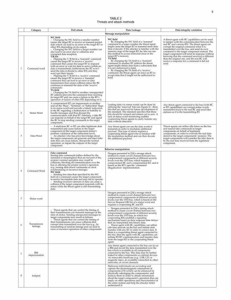
This section describes the threats to the MIL-STD-1553 com-munication protocol, which are categorized by their impact:denial of service, data leakage and data integrity violation.The following subsections elaborate on the different threatsto the 1553 communication bus and provides methods toexecute them. Table 2 provides more detailed description ofeach attack method, categorized by message manipulationand behavior manipulation. Message manipulation refers tomodification of legitimate words (command, data, or status)transmitted over the bus. Behavior manipulation refers toaltering the behavior of the compromised component, forexample, transmitting fake (malicious) messages in unusualtimings or order.
4.3.1 Denial of Service (DoS)DoS can be achieved by damaging physically or logicallythe system’s assets, and will usually require only one threatagent. Physical damage to a component can harm its abilityto perform operations, produce outputs, or transmit themover the bus. In particular, if the damaged component is thebus itself, there could be a complete disconnection betweenall of the components connected to it.
Logical damage refers to exceptions occurred duringcomponent’s normal operation, component’s incorrect oper-ation, or data manipulation and corruption. These scenariosresult in corrupted output or lack of response, which canlead to denying the operation of one or more components.Following a description of possible methods to achieve DoSto an 1553 communication bus.
Message manipulation: compromised components withBC capabilities can change fields of a command word (e.g.WC, T/R, and TA) to control data routing and cause col-lisions. For example: denying a ’transmit’ command fromreaching the GPS by changing its TA field will cause othersubsystems (e.g. navigation, artillery, etc.) rely on outdateddata, which can have severe outcomes. Manipulating statuswords by a threat agent to falsely indicate on errors in thetarget RT might lead to termination of the communicationwith it, although it operates correctly. Data words can beeasily corrupted by different threat agents, by causing col-lisions or manipulating them at the subsystem’s level. Lackof sufficient input validation by the component can lead toan incorrect operation and even crash it.
Behavior manipulation: compromised components thatcan control their transmission times and response delays
8
or behave differently than the command specifies can alsocause collisions and failures to other component, thus leadto DoS.
Possible operational consequences: DoS to the 1553communication bus can have devastating results, especiallybecause it is used for mission critical systems. The attack canbe executed upon detection of some operation in order tointercept it. For example, an attacker that listens to the buscan identify that the system entered a certain geographiczone and deny location data from updating the navigationsystem, or identify that the system is aiming to fire at a targetand deny the firing command from reaching the relevantcomponents.
4.3.2 Data leakage
Data leakage in the context of the MIL-STD-1553 commu-nication bus is the result of unauthorized data transmissionbetween components (i.e. components of different securitylevels) or outside the system.
Message manipulation: by changing the WC or TAfields in a command word, a threat agent can instruct acomponent to transmit exceeding data words, or to transmitdata words to another component (that may have lowersecurity level). Data can also be leaked using the reservedbits of a status word, or by modulating additional payloadon legitimate data words.
Behavior manipulation: threat agents that can controltheir behaviors are capable of creating a covert channelsin order to leak data as presented by Neugen in [24]. Ifthe threat agent has BC capabilities it can also utilize idletime on the bus and initiate unauthorized data transfers.Moreover, if the threat agent has an access to an externaldevice or removable hardware it can utilize it to leak dataoutside the system. Data can also be leaked physically byeavesdropping the electromagnetic emanations of compo-nents.
Possible operational consequences: Leaked data canhelp the attacker conclude information about the operationof the system. Usually vehicle have service ports (e.g. USB)that are easily accessible to maintenance crew for debuggingand investigating the vehicle’s performance. A maliciouscrew member can extract logs and traffic traces from thesystem and pass them to the attacker. Sensitive information,such as: current vehicle location, targets, and destinations,can be leaked by a compromised component outsize the ve-hicle by using legitimate external communication channels(e.g., radio).
4.3.3 Violation of data integrity
Violation of data integrity refers to invalid or incorrect datathat flows inside the system and causes other component tofail or operate incorrectly. Incorrect data can get inside thesystem by a threat agent external to the system (see 4.2.1)or by an inside threat agent that can manipulate messagesexchanged over the bus or send fake data in the behalf ofanother component (i.e., spoofing), and cause the system tobehave abnormally.
Possible operational consequences: by altering the datawords an attacker can cause the system to navigate to thewrong destination, fire at the wrong target, and even to no
fire at all, or withhold/add objects from/to the vehicle’sdashboards and deceive the crew aboard.
5 SEQUENCE-BASED ANOMALY DETECTIONMETHOD FOR THE 1553 COMMUNICATION BUS
To the best of our knowledge, there are no security solu-tions for identifying and/or preventing cyber attacks onthe 1553 communication bus. Existing security solutions(e.g., firewall, intrusion and malware detection, data leakageprevention, access control) are not suitable for the 1553communication bus because they require significant adapta-tion and configuration to the specific operating systems andcommunication protocol. Existing solutions also require theapplication of changes to various components of the 1553communication bus which may be cost prohibitive due toits extensive deployment in various aircrafts and vehicles.
Therefore, we propose adding a lightweight, MIL-STD-1553 tailor-made anomaly detection [1] solution that isbased on continuous monitoring of the messages transmit-ted over the bus and the application of machine learning-based anomaly detection algorithms, in order to identify at-tacks on the bus. In this section we present a sequence-basedanomaly detection module, which is a solution for iden-tifying command word manipulations and timing-relatedbehavior manipulations.
The advantages of the proposed solution are two-fold.First, by using machine learning techniques, which arehighly flexible and adaptive [7], we can provide a robustsolution which can be automatically adapted to any 1553-based system in a very short time. Second, the proposedsolution can be implemented (integrated) as part of a BusMonitoring (BM) module and therefore does not require anychange to the existing modules of the bus.
The sequence-based anomaly detection module focuseson detecting whether the message complies with the prede-fined major frame specification for the specific bus imple-mentation, or whether it arrived out of order or was sent atthe wrong time. Similar to [3], we use time interval analysisof messages and inspect their deviation from their normaltime cycle.
Since most of the messages sent over the bus are peri-odic, it is more likely that command and timing featureswill be useful for identifying anomalous messages. Forthat, we propose the use of sequence mining algorithms,such as a Markov chain model, which are able to derive amodel which represents valid transitions of messages froma training set containing legitimate messages.
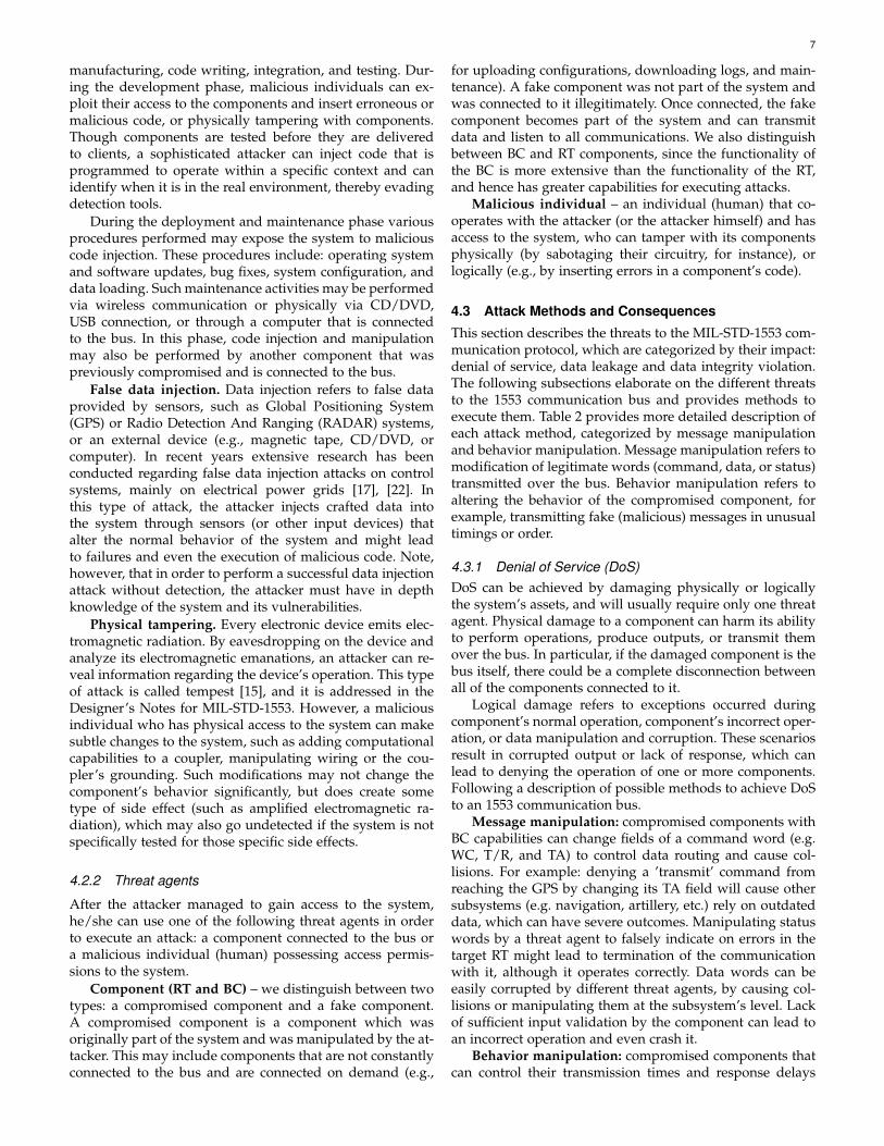
Models which are based on command features can helpdetect messages that are sent out of order. For example,consider a simple case of a major frame that consists of fourmessages: m1,m2,m3 and m4 that are sent as illustrated inFigure5(a). If an attacker tries to utilize the idle time between,m3 and m4 to send its own message - m5 (Figure 5(b)), themodel will identify it immediately as an anomaly, since theonly acceptable transition from m3 is to m4. However, ifthe attacker chooses to utilize m4 (Figure 5(c)), it might bedetected as benign and cause the real m4 to be detectedas an anomaly. In this case the timing features will assistthe model in detecting the anomalous command, since theattacker’s m4 will be sent at a timing that does not comply
9
TABLE 2Threats and attack methods
Category DoS attack Data Leakage Data integrity vaiolation
Message manipulation
1 Command word
WC field– Changing the WC field to a smaller numbercauses the target RT to receive or transmit partialdata which can lead to an error in the target RT orother RTs depending on its output.– Changing the WC field to a larger number canalso lead to an error due to collisions andcorrupted data reception.T/R bit– Flipping the T/R bit in a ’transmit’ commandcauses the target RT to receive a ’receive’command that causes the target RT to respondwith an error or wait for data to arrive (while nodata is transmitted); furthermore the RT won’tsend the data it should to other RTs and theywon’t get their inputs.– Flipping the T/R bit in a ’receive’ commandcauses the target RT to receive a ’transmit’command that can lead to an error or datatransmission that causes collision (since the BCcontinues to transmit the data of the ’receive’command).TA field– Changing the TA field to another/unsupportedRT address prevents the command from reachingits target RT and can cause a failure in the RT’soperation or failure of other RTs depending on it.
WC field– By changing the WC field of a ’transmit’command to a larger number the threat agentmight cause the target RT to transmit more datathan it should. If the attacker is familiar with thememory map of the target RT, he/she can usethis method to access restricted areas in thetarget RT’s memory.TA field– By changing the TA field in a ’transmit’command to another RT address the threatagent might obtain data from a subsystem thatit is not authorized to hold.– By changing the TA field of a ’receive’command, the threat agent can force an RT toaccept data that it might not be authorized tohold.
A threat agent with BC capabilities can be usedto tamper with the communication between thereal BC and various RTs. The threat agent cancorrupt the original command when it istransmitted over the bus, and send its owncommand to the target component instead. Thetarget component will send its response withoutknowing that the command received is differentthan the original one, and the real BC willreceive a response for a command it did notsend.
2 Status Word
A compromised RT can impersonate as anotherand set the ’Busy’, ’Terminal’, or ’Subsystem’ flagsin its status word and provide a falsely indicationto the BC regarding a malfunction or inability tohandle messages and thus disrupt thecommunication with that RT. Similarly, a fake BCcan respond on behalf of the target RT and signalthe BC to stop sending commands to the targetcomponent.
Leaking data via status words can be done byutilizing the ’reserved’ bits (see Figure 2) - threebits that are reserved for future development ofthe standard. The standard specifies that thesebits should be unused and remain set to zero. Alack of status word monitoring enablescooperating threat agents to easily transfer anydata without detection.
Any threat agent connected to the bus (with BCor RT capabilities) can corrupt status wordstransmitted back to the real BC and send fakestatuses as if is the transmitting RT.
3 Data Word
– A malicious BC or RT can alter legitimate datatransmitted and cause failure in the targetcomponent (if the target component doesn’tperform validation at the subsystem level).– An attacker who has prior knowledge aboutthe target component can generate and inject fakedata that can cause failure, disrupt the normaloperation, or impair the outputs of the targetcomponent.
Any threat agent can use the data words ittransmits in order to modulate additionalpayload. This type of attack requires acooperating threat agent who is familiar withthe modulation method and can then decodethe additional payload.
Threat agents can utilize idle times on the busand resend fake commands to targetcomponents on behalf of legitimatecomponents, in order to override the real datastored in the target components’ memory. Thetarget components will consider the fake data tobe the real data received from the legitimatecomponent.
Behavior manipulation
4 Command Word
Fake commandIssuing fake commands (either defined by thestandard or meaningless) that are not part of thesystem’s normal operation may result incollisions, blocking all communication over thebus or affecting the proper system’s operation(e.g. issuing shut-down commands or clocksynchronizing at incorrect timings).WC field– Sending less data than specified by the WCfield of a command causes the target componentto receive incomplete data and may fail to operate.– Sending excessive amount of data can cause acollision if the target component responds with itsstatus while the threat agent is still transmittingdata.
Neugen presented in [24] a storage attackmethod to create covert channel between twocompromised components of different securitylevels over the 1553 bus, which requires acompromised BC and a compromised RT, and isbased on the RT’s specific ’commandillegalization’ implementation.
5 Status word
Neugen presented in [24] a storage attackmethod to create covert channel between twocompromised components of different securitylevels over the 1553 bus, which is based on theService Request (SR) bit of a status word andrequires a cooperating BC and RT.
6 Transmissiontimings
– Threat agents that can control the timing oftheir transmissions can transmit messages at thetime of choice. Sending unexpected messages totarget components may result in failures.– Threat agents that can control the timing oftheir transmissions can cause collisions thatcorrupt data transmitted over the bus (e.g., bytransmitting at random timing) and can lead toerror or incorrect operation of other components.
– Neugen presented in [24] a timing attackmethod to create covert channel between twocompromised components of different securitylevels over the 1553 bus, in which twocooperating RTs establish a signalingmechanism based on their response time delaysthat are interpreted into binary data.– Threat agent with BC capabilities can utilizeidle time periods on the bus and initiate datatransfer with any RT in order to extract data. Ifthere is a cooperating threat agent connected tothe bus, then the agent with BC capabilities caninitiate RT-RT communication and transfer datafrom the target RT to the cooperating threatagent.
7 BMimpersonation
Any threat agent connected to the bus can act asa BM and record the data transmitted over thebus which is available to all componentsconnected to the bus. This data may be furtherleaked to other components or external devicesvia removable hardware (e.g., USB, CD, ormagnetic tape), an available connection to othernetworks, or covert channels.
8 tempest
Malicious individuals can eavesdrop andcapture the electromagnetic emanations ofcomponents [15] (which can be enhanced byphysically sabotaging the components), andanalyze them in order to obtain informationabout the target component’s operation that canimply on other operations and characteristics ofthe entire system and help the attacker betterunderstand it.
10
with its normal transmission timing, as defined by the majorframe.
If a message is found anomalous by this module, an alertis generated.
Fig. 5. Simple major frame examples for: (a) a legitimate major frame, (b)new message injection attack, (c) legitimate message injection attack.
5.1 Detection algorithmAs previously described, we detect anomalous messagesbased their timing and order. We opt to use the Markovchain model as the basis for our detection mechanism, inorder to represent the normal behavior of the monitoredbus (similar to [28]).
We distinguish between two types of messages: periodicand aperiodic. A periodic message is sent by the BC atfixed time intervals (referred to as time cycles). An aperiodicmessage is sent by the BC as a result of an event or a ServiceRequest.
In order to profile both periodic and aperiodic messageswe use two Markov models - one for each type. The periodicMarkov model’s states are defined by command and timingfeatures (see Table 3). Aperiodic messages, which are sentupon demand, are likely to be found anomalous by the pe-riodic model which uses time-related features. Therefore, asecond model is maintained, the aperiodic Markov model, inwhich each of the states are represented only by commandfeatures. Next, we provide a detailed description of thetraining and detection processes of the proposed method.
TABLE 3Extracted features used for defining the Markov model states
Featurename Values Description
Commandfeatures
Src.TerminalAddress
0-31,N/A
The address of the terminal sending thedata. If the terminal is the BC, the addressis ’N/A’.
Src. Sub-address
0-31,N/A
The subaddress from which the data issent in the source terminal. If the terminalis the BC, the subaddress is ’N/A’.
Dst.TerminalAddress
0-31,N/A
The address of the terminal receiving thedata. If the terminal is the BC, the addressis ’N/A’.
Dst. Sub-address
0-31,N/A
The subaddress to which the data is savedin the destination terminal. If the terminalis the BC, the subaddress is ’N/A’.
Channel A, B The channel on which the message wassent.
WordCount 0-32 The number of data words sent in the
message frame.Is Mode
Code true, false Whether the command is a mode code ornot.
Timingfeatures
TimeCycle numeric
The time cycle (in microseconds) of themessage. Note that a message can haveseveral different time cycles.
LabelBenign,
Anomaly,N/A
The message label: ’Benign’, ’Anomaly’, or’N/A’ (for cases the model cannot classifythe message).
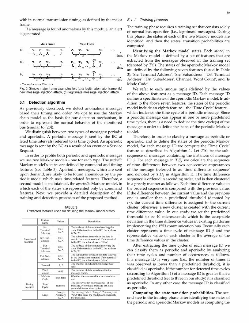
5.1.1 Training process
The training phase requires a training set that consists solelyof normal bus operation (i.e., legitimate messages). Duringthis phase, the states of each of the two Markov models areidentified, and then the states’ transition probabilities arecomputed.
Identifying the Markov model states. Each statej inthe Markov model is defined by a set of features that areextracted from the messages observed in the training set(denoted by TS). The states of the aperiodic Markov modelare defined by the following seven features (listed in Table3): ’Src. Terminal Address’, ’Src. Subaddress’, ’Dst. TerminalAddress’, ’Dst. Subaddress’, Channel, ’Word Count’, and ’IsMode Code’.
We refer to each unique tuple (defined by the valuesof the above features) as a message ID. Each message IDdefines a specific state of the aperiodic Markov model. In ad-dition to the above seven features, the states of the periodicmodel include an eighth feature – the ’Time Cycle’ feature –which indicates the time cycle of a periodic message. Sincea periodic message can appear in one or more predefinedtime cycles, there is a need to deduce the time cycle(s) of themessage in order to define the states of the periodic Markovmodel.
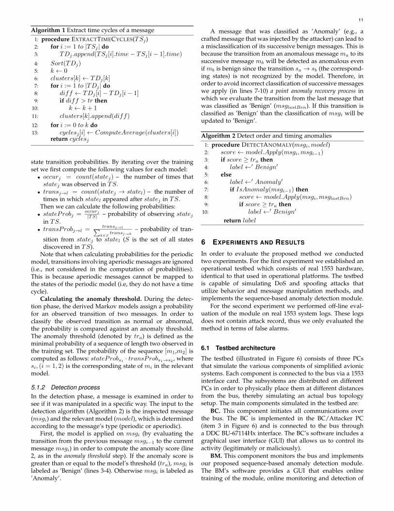
Therefore, in order to classify a message as periodic oraperiodic, and to define the states of the periodic Markovmodel, for each message ID we compute the ’Time Cycle’feature as described in Algorithm 1. Let TSj be the sub-sequence of messages containing the instances of messageID j. For each message in TSj we calculate the sequenceof time differences between two consecutive appearancesof the message (referred to as ’time difference sequence’and denoted by TDj in Algorithm 1). The time differencesequence is ordered in ascending order, and is then clusteredin a greedy manner as follows. Each time difference value inthe ordered sequence is compared with the previous value.If the difference between the current value and the previousone is smaller than a predefined threshold (denoted bytr), the current time difference is assigned to the currentcluster; otherwise, a new cluster is created with the currenttime difference value. In our study we set the predefinedthreshold to be 40 microseconds which is the acceptabledeviation in the time difference values in existing platformsimplementing the 1553 communication bus. Eventually eachcluster represents a time cycle of message ID j and therepresentative value of each cluster is the average of thetime difference values in the cluster.
After extracting the time cycles of each message ID wecan classify them as periodic and aperiodic by analyzingtheir time cycles and number of occurrences as follows.If a message ID is very rare (i.e., the number of times itwas observed is lower than a predefined threshold), it isclassified as aperiodic. If the number for detected time cycles(according to Algorithm 1) of a message ID is greater than apredefined threshold (set to three in our study) it is classifiedas aperiodic. In any other case the message ID is classifiedas periodic.
Computing the state transition probabilities. The sec-ond step in the training phase, after identifying the states ofthe periodic and aperiodic Markov models, is computing the
11
Algorithm 1 Extract time cycles of a message1: procedure EXTRACTTIMECYCLES(TSj)2: for i := 1 to |TSj | do3: TDj .append(TSj [i].time− TSj [i− 1].time)
4: Sort(TDj)5: k ← 06: clusters[k]← TDj [k]7: for i := 1 to |TDj | do8: diff ← TDj [i]− TDj [i− 1]9: if diff > tr then
10: k ← k + 111: clusters[k].append(diff)
12: for i := 0 to k do13: cyclesj [i]← ComputeAverage(clusters[i])
return cyclesj
state transition probabilities. By iterating over the trainingset we first compute the following values for each model:• occurj = count(statej) – the number of times thatstatej was observed in TS.
• transj→l = count(statej → statel) – the number oftimes in which statel appeared after statej in TS.
Then we can calculate the following probabilities:• stateProbj =
occurj|TS| – probability of observing statej
in TS.• transProbj→l =
transj→l∑k∈S
transj→k– probability of tran-
sition from statej to statel (S is the set of all statesdiscovered in TS).
Note that when calculating probabilities for the periodicmodel, transitions involving aperiodic messages are ignored(i.e., not considered in the computation of probabilities).This is because aperiodic messages cannot be mapped tothe states of the periodic model (i.e, they do not have a timecycle).
Calculating the anomaly threshold. During the detec-tion phase, the derived Markov models assign a probabilityfor an observed transition of two messages. In order toclassify the observed transition as normal or abnormal,the probability is compared against an anomaly threshold.The anomaly threshold (denoted by tra) is defined as theminimal probability of a sequence of length two observed inthe training set. The probability of the sequence [m1,m2] iscomputed as follows: stateProbs1 · transProbs1→s2 , wheresi, (i = 1, 2) is the corresponding state of mi in the relevantmodel.
5.1.2 Detection processIn the detection phase, a message is examined in order tosee if it was manipulated in a specific way. The input to thedetection algorithm (Algorithm 2) is the inspected message(msgi) and the relevant model (model), which is determinedaccording to the message’s type (periodic or aperiodic).
First, the model is applied on msgi (by evaluating thetransition from the previous message msgi−1 to the currentmessage msgi) in order to compute the anomaly score (line2, as in the anomaly threshold step). If the anomaly score isgreater than or equal to the model’s threshold (tra), msgi islabeled as ’Benign’ (lines 3-4). Otherwise msgi is labeled as’Anomaly’.
A message that was classified as ’Anomaly’ (e.g., acrafted message that was injected by the attacker) can lead toa misclassification of its successive benign messages. This isbecause the transition from an anomalous message ma to itssuccessive message mb will be detected as anomalous evenif mb is benign since the transition sa → sb (the correspond-ing states) is not recognized by the model. Therefore, inorder to avoid incorrect classification of successive messageswe apply (in lines 7-10) a point anomaly recovery process inwhich we evaluate the transition from the last message thatwas classified as ’Benign’ (msglastBen). If this transition isclassified as ’Benign’ than the classification of msgi will beupdated to ’Benign’.
Algorithm 2 Detect order and timing anomalies1: procedure DETECTANOMALY(msgi,model)2: score← model.Apply(msgi,msgi−1)3: if score ≥ tra then4: label←′ Benign′
5: else6: label←′ Anomaly′
7: if IsAnomaly(msgi−1) then8: score← model.Apply(msgi,msglastBen)9: if score ≥ tra then
10: label←′ Benign′
return label
6 EXPERIMENTS AND RESULTS
In order to evaluate the proposed method we conductedtwo experiments. For the first experiment we established anoperational testbed which consists of real 1553 hardware,identical to that used in operational platforms. The testbedis capable of simulating DoS and spoofing attacks thatutilize behavior and message manipulation methods, andimplements the sequence-based anomaly detection module.
For the second experiment we performed off-line eval-uation of the module on real 1553 system logs. These logsdoes not contain attack record, thus we only evaluated themethod in terms of false alarms.
6.1 Testbed architecture
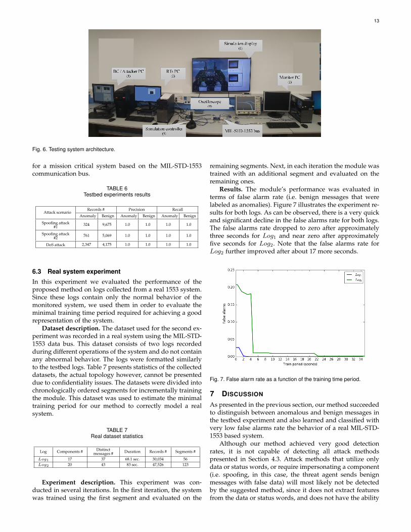
The testbed (illustrated in Figure 6) consists of three PCsthat simulate the various components of simplified avionicsystems. Each component is connected to the bus via a 1553interface card. The subsystems are distributed on differentPCs in order to physically place them at different distancesfrom the bus, thereby simulating an actual bus topologysetup. The main components simulated in the testbed are:
BC. This component initiates all communications overthe bus. The BC is implemented in the BC/Attacker PC(item 3 in Figure 6) and is connected to the bus througha DDC BU-67114Hx interface. The BC’s software includes agraphical user interface (GUI) that allows us to control itsactivity (legitimately or maliciously).
BM. This component monitors the bus and implementsour proposed sequence-based anomaly detection module.The BM’s software provides a GUI that enables onlinetraining of the module, online monitoring and detection of
12
anomalous messages transmitted over the bus, and display-ing visual alerts when such messages are detected. In addi-tion, the BM writes to a log file all monitored messages andtheir labels (assigned by the anomaly detection algorithm)for offline analysis. The BM is implemented in the MonitorPC (item 1 in Figure 6) and is connected to the bus througha DDC BU-67114Hx interface.
RTs. The RTs’ programs are implemented on the RTs PC(item 2 in Figure 6). The RTs PC is connected to the busthrough two interfaces: a DDC BU-67114Hx interface andan Excalibur EXC-4000PCIe card which logically enables upto 32 connections. These RTs are used for benign activitysimulation, and their software also provides a simple GUIwhich enables us to start or stop their operation.
Attacker component. This component has the function-ality of either a BC or an RT and is responsible for executingvarious attacks as a fake RT/BC (i.e., illegitimately con-nected to the bus) or a compromised RT/BC. The attackercomponent is controlled manually through a GUI, and itssoftware is implemented in the same PC as the BC (item 3in Figure 6) and is connected to the bus via another DDCBU-67114Hx interface.
The testbed also contains: (1) an oscilloscope (item 4 inFigure 6) for visualizing electric signals transmitted overthe bus, (2) a controller (item 5 in Figure 6) for simulatinguser operations, and (3) a display (item 6 in Figure 6) forvisualizing the physical impact on the simulated operationson the simulated system.
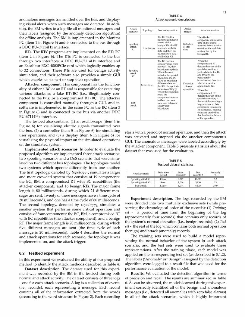
Implemented attack scenarios. In order to evaluate theproposed algorithm we implemented three attack scenarios:two spoofing scenarios and a DoS scenario that were simu-lated on two different bus topologies. The topologies modeltwo systems which operate differently from one another.The first topology, denoted by topology1, simulates a largerand more crowded system that consists of 19 components:the BC, BM, a compromised RT with BC capabilities (theattacker component), and 16 benign RTs. The major framelength is 80 milliseconds, during which 21 different mes-sages are sent. Twenty of these messages have a time cycle of20 milliseconds, and one has a time cycle of 80 milliseconds.The second topology, denoted by topology2, simulates asmaller system that performs some critical operation andconsists of four components: the BC, BM, a compromised RTwith BC capabilities (the attacker component), and a benignRT. The major frame length is 20 milliseconds, during whichfive different messages are sent (the time cycle of eachmessage is 20 milliseconds). Table 4 describes the normaland attack operations for each scenario, the topology it wasimplemented on, and the attack trigger.
6.2 Testbed experiment
In this experiment we evaluated the ability of our proposedmethod to identify the attack methods described in Table 4.
Dataset description. The dataset used for this experi-ment was recorded by the BM in the testbed during bothnormal and attack activity. The dataset consists of three logs– one for each attack scenario. A log is a collection of events(i.e., records), each representing a message. Each recordcontains all of the information extracted from the words(according to the word structure in Figure 2). Each recording
TABLE 4Attack scenario descriptions
Attackscenario Topology Normal operation Attack
trigger Attack operation
Spoofingattack
#1 topology1
The BC sends atransmit commandto one of thebenign RTs, the RTresponds with itsdata and then theBC transmits datato all other RTs.
Detectionof idletime
The attackercomponent utilizes idletime on the bus totransmit fake data thatoverrides the real datasent earlier by thebenign RT.
Spoofingattack
#2
topology2
The BC queriescertain values fromthe two TRs, thenbroadcasts updates.When the userinitiates the specialoperation, the BCstarts to broadcastdifferent data andthe RTs change theirstates accordingly.When the operationends, thecomponents returnto their previousstate and behavior(query andbroadcast)
Detectionof user
operation
When thecompromised RTdetects the start of thespecial operation, itpretends to be the BCand thwarts theoperation bybroadcasting fake datawhich causes theoperation to fail.
DoSattack
When thecompromised RTdetects the start of thespecial operation, itthwarts it by sending alarge amount of fakecommands to randomRT addresses, causingcollisions on the busthat lead to the failureof the operation.
starts with a period of normal operation, and then the attackwas activated and stopped via the attacker component’sGUI. The anomalous messages were labeled accordingly bythe attacker component. Table 5 presents statistics about thedataset that was used for the evaluation.
TABLE 5Testbed dataset statistics
Attack scenario Train timeperiod
Trainrecords #
Testrecords #
Anomaly%
Spoofing attack #1 4.5 sec. 4,579 10,021 3.2Spoofing attack #2 4 sec. 1,004 5,836 13
DoS attack 4.2 sec. 1,074 6,528 35.9
Experiment description. The logs recorded by the BMwere divided into two mutually exclusive sets (while pre-serving the chronological order of the records): (1) Trainingset - a period of time from the beginning of the log(approximately four seconds) that contains only records ofthe system’s normal operation (i.e., benign records); (2) Testset - the rest of the log which contains both normal operation(benign) and attack (anomaly) records.
The training sets were used to build a model repre-senting the normal behavior of the system in each attackscenario, and the test sets were used to evaluate theserepresentations. After the training phase, each model wasapplied on the corresponding test set (as described in 5.1.2).The labels (’Anomaly’ or ’Benign’) assigned by the detectionalgorithm were logged to a result file that was used for theperformance evaluation of the model.
Results. We evaluated the detection algorithm in termsof precision and recall. The results are summarized in Table6. As can be observed, the models learned during this exper-iment correctly identified all of the benign and anomalousmessages (i.e., detected all anomalies with zero false alarms)in all of the attack scenarios, which is highly important
13
Fig. 6. Testing system architecture.
for a mission critical system based on the MIL-STD-1553communication bus.
TABLE 6Testbed experiments results
Attack scenarioRecords # Precision Recall
Anomaly Benign Anomaly Benign Anomaly Benign
Spoofing attack#1 324 9,675 1.0 1.0 1.0 1.0
Spoofing attack#2 761 5,069 1.0 1.0 1.0 1.0
DoS attack 2,347 4,175 1.0 1.0 1.0 1.0
6.3 Real system experiment
In this experiment we evaluated the performance of theproposed method on logs collected from a real 1553 system.Since these logs contain only the normal behavior of themonitored system, we used them in order to evaluate theminimal training time period required for achieving a goodrepresentation of the system.
Dataset description. The dataset used for the second ex-periment was recorded in a real system using the MIL-STD-1553 data bus. This dataset consists of two logs recordedduring different operations of the system and do not containany abnormal behavior. The logs were formatted similarlyto the testbed logs. Table 7 presents statistics of the collecteddatasets, the actual topology however, cannot be presenteddue to confidentiality issues. The datasets were divided intochronologically ordered segments for incrementally trainingthe module. This dataset was used to estimate the minimaltraining period for our method to correctly model a realsystem.
TABLE 7Real dataset statistics
Log Components # Distinctmessages # Duration Records # Segments #
Log1 17 37 68.1 sec. 30,034 56Log2 20 43 83 sec. 47,526 123
Experiment description. This experiment was con-ducted in several iterations. In the first iteration, the systemwas trained using the first segment and evaluated on the
remaining segments. Next, in each iteration the module wastrained with an additional segment and evaluated on theremaining ones.
Results. The module’s performance was evaluated interms of false alarm rate (i.e. benign messages that werelabeled as anomalies). Figure 7 illustrates the experiment re-sults for both logs. As can be observed, there is a very quickand significant decline in the false alarms rate for both logs.The false alarms rate dropped to zero after approximatelythree seconds for Log1 and near zero after approximatelyfive seconds for Log2. Note that the false alarms rate forLog2 further improved after about 17 more seconds.
Fig. 7. False alarm rate as a function of the training time period.
7 DISCUSSION
As presented in the previous section, our method succeededto distinguish between anomalous and benign messages inthe testbed experiment and also learned and classified withvery low false alarms rate the behavior of a real MIL-STD-1553 based system.
Although our method achieved very good detectionrates, it is not capable of detecting all attack methodspresented in Section 4.3. Attack methods that utilize onlydata or status words, or require impersonating a component(i.e. spoofing, in this case, the threat agent sends benignmessages with false data) will most likely not be detectedby the suggested method, since it does not extract featuresfrom the data or status words, and does not have the ability
14
to physically authenticate the components connected to thebus.
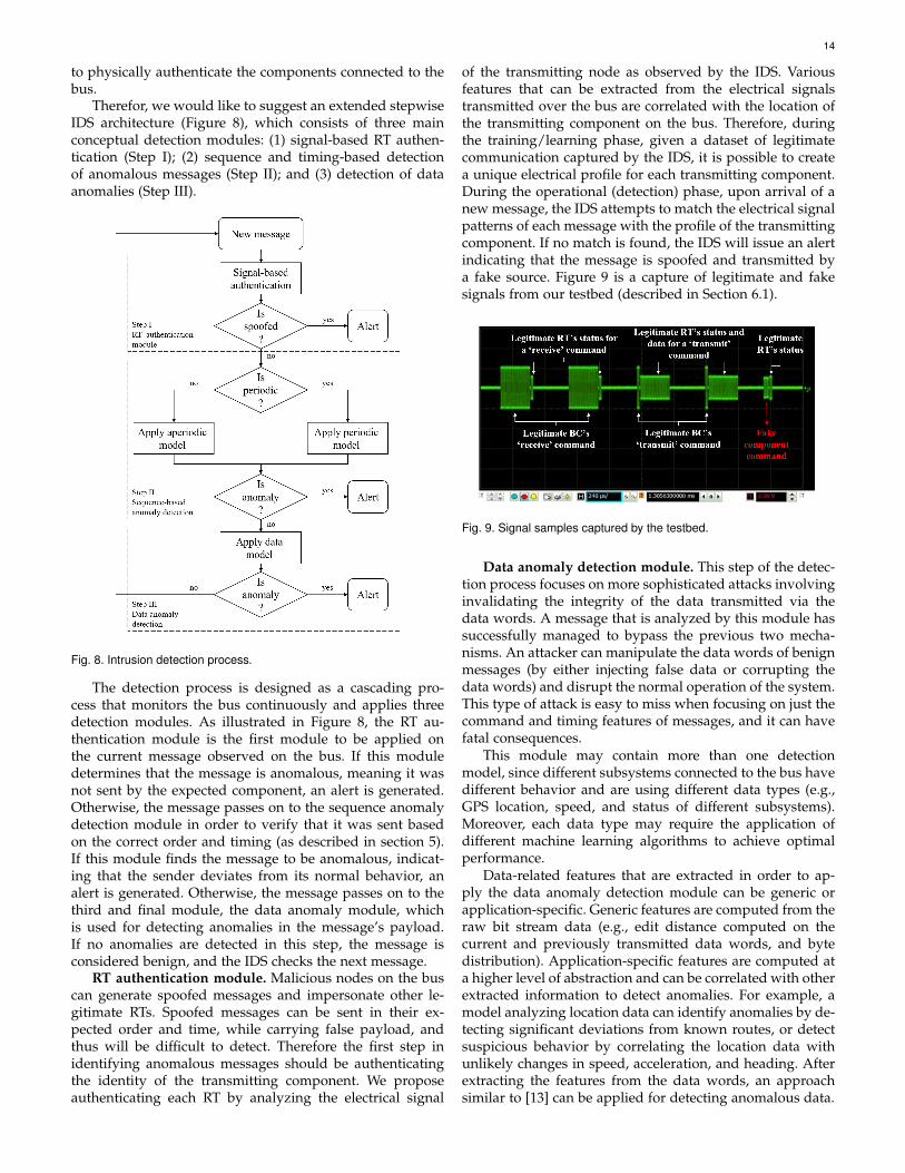
Therefor, we would like to suggest an extended stepwiseIDS architecture (Figure 8), which consists of three mainconceptual detection modules: (1) signal-based RT authen-tication (Step I); (2) sequence and timing-based detectionof anomalous messages (Step II); and (3) detection of dataanomalies (Step III).
Fig. 8. Intrusion detection process.
The detection process is designed as a cascading pro-cess that monitors the bus continuously and applies threedetection modules. As illustrated in Figure 8, the RT au-thentication module is the first module to be applied onthe current message observed on the bus. If this moduledetermines that the message is anomalous, meaning it wasnot sent by the expected component, an alert is generated.Otherwise, the message passes on to the sequence anomalydetection module in order to verify that it was sent basedon the correct order and timing (as described in section 5).If this module finds the message to be anomalous, indicat-ing that the sender deviates from its normal behavior, analert is generated. Otherwise, the message passes on to thethird and final module, the data anomaly module, whichis used for detecting anomalies in the message’s payload.If no anomalies are detected in this step, the message isconsidered benign, and the IDS checks the next message.
RT authentication module. Malicious nodes on the buscan generate spoofed messages and impersonate other le-gitimate RTs. Spoofed messages can be sent in their ex-pected order and time, while carrying false payload, andthus will be difficult to detect. Therefore the first step inidentifying anomalous messages should be authenticatingthe identity of the transmitting component. We proposeauthenticating each RT by analyzing the electrical signal
of the transmitting node as observed by the IDS. Variousfeatures that can be extracted from the electrical signalstransmitted over the bus are correlated with the location ofthe transmitting component on the bus. Therefore, duringthe training/learning phase, given a dataset of legitimatecommunication captured by the IDS, it is possible to createa unique electrical profile for each transmitting component.During the operational (detection) phase, upon arrival of anew message, the IDS attempts to match the electrical signalpatterns of each message with the profile of the transmittingcomponent. If no match is found, the IDS will issue an alertindicating that the message is spoofed and transmitted bya fake source. Figure 9 is a capture of legitimate and fakesignals from our testbed (described in Section 6.1).
Fig. 9. Signal samples captured by the testbed.
Data anomaly detection module. This step of the detec-tion process focuses on more sophisticated attacks involvinginvalidating the integrity of the data transmitted via thedata words. A message that is analyzed by this module hassuccessfully managed to bypass the previous two mecha-nisms. An attacker can manipulate the data words of benignmessages (by either injecting false data or corrupting thedata words) and disrupt the normal operation of the system.This type of attack is easy to miss when focusing on just thecommand and timing features of messages, and it can havefatal consequences.
This module may contain more than one detectionmodel, since different subsystems connected to the bus havedifferent behavior and are using different data types (e.g.,GPS location, speed, and status of different subsystems).Moreover, each data type may require the application ofdifferent machine learning algorithms to achieve optimalperformance.
Data-related features that are extracted in order to ap-ply the data anomaly detection module can be generic orapplication-specific. Generic features are computed from theraw bit stream data (e.g., edit distance computed on thecurrent and previously transmitted data words, and bytedistribution). Application-specific features are computed ata higher level of abstraction and can be correlated with otherextracted information to detect anomalies. For example, amodel analyzing location data can identify anomalies by de-tecting significant deviations from known routes, or detectsuspicious behavior by correlating the location data withunlikely changes in speed, acceleration, and heading. Afterextracting the features from the data words, an approachsimilar to [13] can be applied for detecting anomalous data.
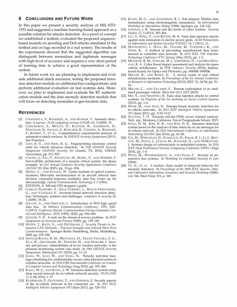
15
8 CONCLUSIONS AND FUTURE WORK
In this paper we present a security analysis of MIL-STD-1553 and suggested a machine learning-based approach as apossible solution for attacks detection. As a proof of conceptwe established a testbed, evaluated the proposed sequence-based module on spoofing and DoS attacks simulated in thetestbed and on logs recorded in a real system. The results ofthe experiments showed that the suggested algorithm candistinguish between anomalous and legitimate messageswith high level of accuracy and requires a very short periodof training time to achieve a good representation of thesystem.
In future work we are planning to implement and eval-uate additional attack scenarios, testing the proposed intru-sion detection module on additional bus configurations, andperform additional evaluation on real systems data. More-over, we plan to implement and evaluate the RT authenti-cation module and the data anomaly detection module thatwill focus on detecting anomalies in geo-location data.
REFERENCES
[1] CHANDOLA, V., BANERJEE, A., AND KUMAR, V. Anomaly detec-tion: A survey. ACM computing surveys (CSUR) 41, 3 (2009), 15.
[2] CHECKOWAY, S., MCCOY, D., KANTOR, B., ANDERSON, D.,SHACHAM, H., SAVAGE, S., KOSCHER, K., CZESKIS, A., ROESNER,F., KOHNO, T., ET AL. Comprehensive experimental analyses ofautomotive attack surfaces. In USENIX Security Symposium (2011),San Francisco.
[3] CHO, K.-T., AND SHIN, K. G. Fingerprinting electronic controlunits for vehicle intrusion detection. In 25th USENIX SecuritySymposium (USENIX Security 16) (Austin, TX, 2016), USENIXAssociation, pp. 911–927.
[4] CHONG, J., PAL, P., ATIGETCHI, M., RUBEL, P., AND WEBBER, F.Survivability architecture of a mission critical system: the dpasaexample. In 21st Annual Computer Security Applications Conference(ACSAC’05) (Dec 2005), pp. 10 pp.–504.
[5] DESHU, C., AND JIXIANG, W. Guilin institute of optical commu-nications; fiber-optic mechanization of an aircraft internal timedivision command/response multiplex data bus (come up fordiscussions)[j]. Optical Communication Technology Z 1 (1991).
[6] EDITION, S. Mil-std-1553 designer’s guide.[7] GARCIA-TEODORO, P., DIAZ-VERDEJO, J., MACIA-FERNANDEZ,
G., AND VAZQUEZ, E. Anomaly-based network intrusion detec-tion: Techniques, systems and challenges. computers & security 28,1 (2009), 18–28.
[8] GILLEN, A., AND SHELTON, J. Introduction of 3910 high speeddata bus. In Military Communications Conference, 1992. MIL-COM’92, Conference Record. Communications-Fusing Command, Con-trol and Intelligence., IEEE (1992), IEEE, pp. 956–960.
[9] GLIGOR, V. D. A note on the denial-of-service problem. In IEEESymposium on Security and Privacy (1983), pp. 139–149.
[10] HOPPE, T., KILTZ, S., AND DITTMANN, J. Security Threats to Au-tomotive CAN Networks – Practical Examples and Selected Short-TermCountermeasures. Springer Berlin Heidelberg, Berlin, Heidelberg,2008, pp. 235–248.
[11] ISHTIAQ ROUFA, R. M., MUSTAFAA, H., TRAVIS TAYLORA, S. O.,XUA, W., GRUTESERB, M., TRAPPEB, W., AND SESKARB, I. Secu-rity and privacy vulnerabilities of in-car wireless networks: A tirepressure monitoring system case study. In 19th USENIX SecuritySymposium, Washington DC (2010), pp. 11–13.
[12] JIANG, W., GUO, W., AND SANG, N. Periodic real-time mes-sage scheduling for confidentiality-aware cyber-physical system inwireless networks. In 2010 Fifth International Conference on Frontierof Computer Science and Technology (Aug 2010), pp. 355–360.
[13] KANG, M.-J., AND KANG, J.-W. Intrusion detection system usingdeep neural network for in-vehicle network security. PLOS ONE11, 6 (06 2016), 1–17.
[14] KLEBERGER, P., OLOVSSON, T., AND JONSSON, E. Security aspectsof the in-vehicle network in the connected car. In 2011 IEEEIntelligent Vehicles Symposium (IV) (June 2011), pp. 528–533.
[15] KUHN, M. G., AND ANDERSON, R. J. Soft tempest: Hidden datatransmission using electromagnetic emanations. In InternationalWorkshop on Information Hiding (1998), Springer, pp. 124–142.
[16] LINDSAY, J. R. Stuxnet and the limits of cyber warfare. SecurityStudies 22, 3 (2013), 365–404.
[17] LIU, Y., NING, P., AND REITER, M. K. False data injection attacksagainst state estimation in electric power grids. ACM Transactionson Information and System Security (TISSEC) 14, 1 (2011), 13.
[18] MATSUMOTO, T., HATA, M., TANABE, M., YOSHIOKA, K., ANDOISHI, K. A method of preventing unauthorized data trans-mission in controller area network. In 2012 IEEE 75th VehicularTechnology Conference (VTC Spring) (May 2012), pp. 1–5.
[19] MCGRAW, R. M., FOWLER, M. J., UMPHRESS, D., AND MACDON-ALD, R. A. Cyber threat impact assessment and analysis for spacevehicle architectures. In SPIE Defense+ Security (2014), Interna-tional Society for Optics and Photonics, pp. 90850K–90850K.
[20] MILLER, B., AND ROWE, D. A survey scada of and criticalinfrastructure incidents. In Proceedings of the 1st Annual Conferenceon Research in Information Technology (2012), RIIT ’12, ACM, pp. 51–56.
[21] MILLER, C., AND VALASEK, C. Remote exploitation of an unal-tered passenger vehicle. Black Hat USA 2015 (2015).
[22] MO, Y., AND SINOPOLI, B. False data injection attacks in controlsystems. In Preprints of the 1st workshop on Secure Control Systems(2010), pp. 1–6.
[23] MTER, M., AND ASAJ, N. Entropy-based anomaly detection forin-vehicle networks. In 2011 IEEE Intelligent Vehicles Symposium(IV) (June 2011), pp. 1110–1115.
[24] NGUYEN, T. D. Towards mil-std-1553b covert channel analysis.Tech. rep., Monterey, California. Naval Postgraduate School, 2015.
[25] SONG, H. M., KIM, H. R., AND KIM, H. K. Intrusion detectionsystem based on the analysis of time intervals of can messages forin-vehicle network. In 2016 International Conference on InformationNetworking (ICOIN) (Jan 2016), pp. 63–68.
[26] VAI, M., WHELIHAN, D., EVANCICH, N., KWAK, K. J., LI, J., BRIT-TON, M., FOLEY, J., LYNCH, M., SCHAFER, D., AND DEMATTEIS,J. Systems design of cybersecurity in embedded systems. In 2016IEEE High Performance Extreme Computing Conference (HPEC) (Sept2016), pp. 1–6.
[27] WOLF, M., WEIMERSKIRCH, A., AND PAAR, C. Security in au-tomotive bus systems. In Workshop on Embedded Security in Cars(2004).
[28] YE, N., ET AL. A markov chain model of temporal behavior foranomaly detection. In Proceedings of the 2000 IEEE Systems, Man,and Cybernetics Information Assurance and Security Workshop (2000),vol. 166, West Point, NY, p. 169.
Related Documents