1 Pipelining • Reconsider the data path we just did • Each instruction takes from 3 to 5 clock cycles • However, there are parts of hardware that are idle many time • We can reorganize the operation • Make each hardware block independent – 1. Instruction Fetch Unit – 2. Register Read Unit – 3. ALU Unit – 4. Data Memory Read/Write Unit – 5. Register Write Unit • Units in 3 and 5 cannot be independent, but operations can be • Let each unit just do its required job for each instruction • If for some instruction, a unit need not do anything, it can simply perform a noop

Welcome message from author
This document is posted to help you gain knowledge. Please leave a comment to let me know what you think about it! Share it to your friends and learn new things together.
Transcript

1
Pipelining
• Reconsider the data path we just did
• Each instruction takes from 3 to 5 clock cycles
• However, there are parts of hardware that are idle many time
• We can reorganize the operation
• Make each hardware block independent
– 1. Instruction Fetch Unit
– 2. Register Read Unit
– 3. ALU Unit
– 4. Data Memory Read/Write Unit
– 5. Register Write Unit
• Units in 3 and 5 cannot be independent, but operations can be
• Let each unit just do its required job for each instruction
• If for some instruction, a unit need not do anything, it can simply perform a noop
2
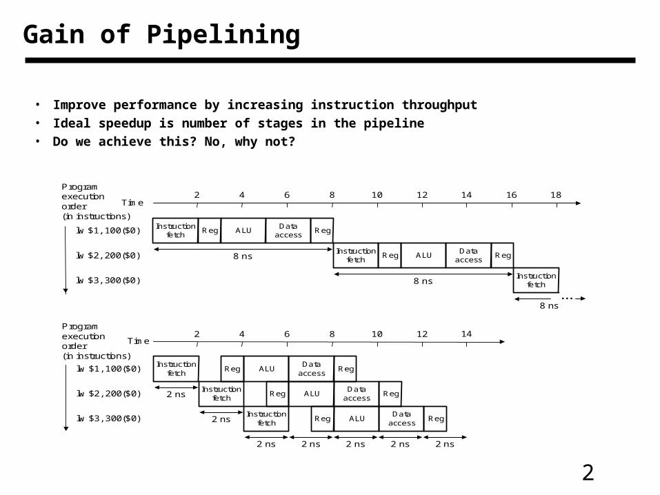
Gain of Pipelining
• Improve performance by increasing instruction throughput
• Ideal speedup is number of stages in the pipeline
• Do we achieve this? No, why not?
Instructionfetch
Reg ALUData
accessReg
8 nsInstruction
fetchReg ALU
Dataaccess
Reg
8 nsInstruction
fetch
8 ns
Time
lw $1, 100($0)
lw $2, 200($0)
lw $3, 300($0)
2 4 6 8 10 12 14 16 18
2 4 6 8 10 12 14
...
Programexecutionorder(in instructions)
Instructionfetch
Reg ALUData
accessReg
Time
lw $1, 100($0)
lw $2, 200($0)
lw $3, 300($0)
2 nsInstruction
fetchReg ALU
Dataaccess
Reg
2 nsInstruction
fetchReg ALU
Dataaccess
Reg
2 ns 2 ns 2 ns 2 ns 2 ns
Programexecutionorder(in instructions)
3
Pipelining
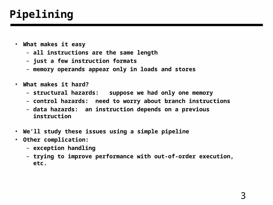
• What makes it easy– all instructions are the same length– just a few instruction formats– memory operands appear only in loads and stores
• What makes it hard?– structural hazards: suppose we had only one memory– control hazards: need to worry about branch instructions– data hazards: an instruction depends on a previous instruction
• We’ll study these issues using a simple pipeline• Other complication:
– exception handling– trying to improve performance with out-of-order execution, etc.

4
Basic Idea
• What do we need to add to actually split the datapath into stages?
Instructionmemory
Address
4
32
0
Add Addresult
Shiftleft 2
Instruction
Mux
0
1
Add
PC
0Writedata
Mux
1Registers
Readdata 1
Readdata 2
Readregister 1
Readregister 2
16Sign
extend
Writeregister
Writedata
ReaddataAddress
Datamemory
1
ALUresult
Mux
ALUZero
IF: Instruction fetch ID: Instruction decode/register file read
EX: Execute/address calculation
MEM: Memory access WB: Write back
5
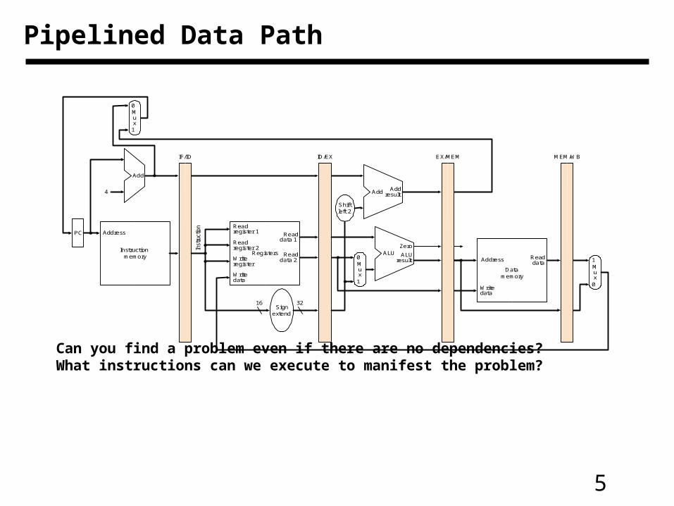
Pipelined Data Path
Can you find a problem even if there are no dependencies? What instructions can we execute to manifest the problem?
Instructionmemory
Address
4
32
0
Add Addresult
Shiftleft 2
Inst
ruct
ion
IF/ID EX/MEM MEM/WB
Mux
0
1
Add
PC
0Writedata
Mux
1Registers
Readdata 1
Readdata 2
Readregister 1
Readregister 2
16Sign
extend
Writeregister
Writedata
Readdata
1
ALUresult
Mux
ALUZero
ID/EX
Datamemory
Address

6
Corrected Data Path
Instructionmemory
Address
4
32
0
Add Addresult
Shiftleft 2
Inst
ruct
ion
IF/ID EX/MEM MEM/WB
Mux
0
1
Add
PC
0
Address
Writedata
Mux
1Registers
Readdata 1
Readdata 2
Readregister 1
Readregister 2
16Sign
extend
Writeregister
Writedata
Readdata
Datamemory
1
ALUresult
Mux
ALUZero
ID/EX
7
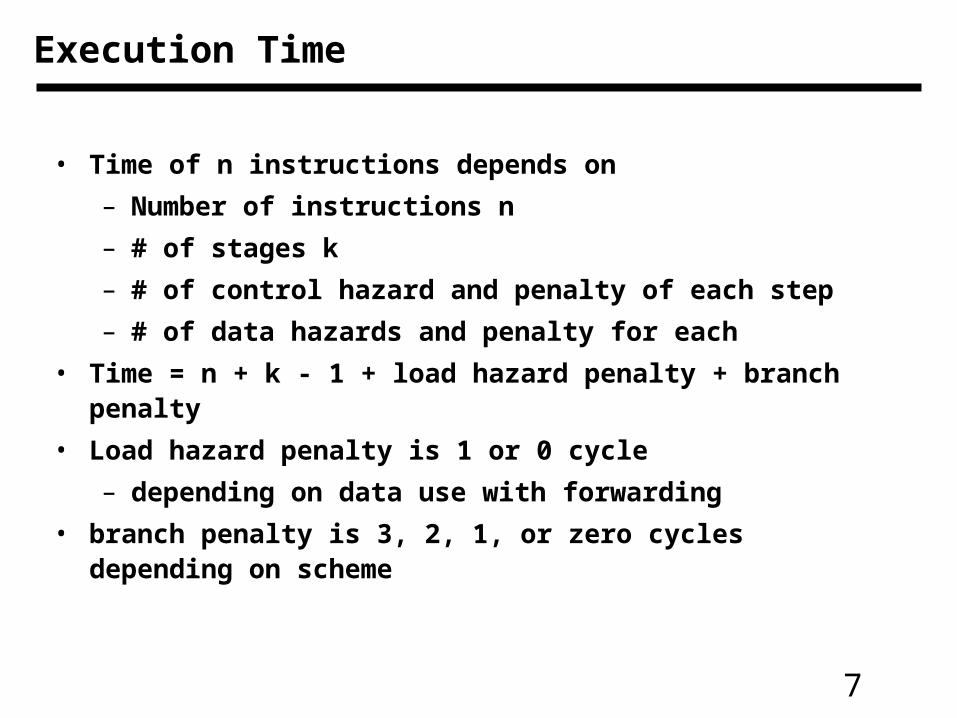
Execution Time
• Time of n instructions depends on
– Number of instructions n
– # of stages k
– # of control hazard and penalty of each step
– # of data hazards and penalty for each
• Time = n + k - 1 + load hazard penalty + branch penalty
• Load hazard penalty is 1 or 0 cycle
– depending on data use with forwarding
• branch penalty is 3, 2, 1, or zero cycles depending on scheme

8
Design and Performance Issues With Pipelining
• Pipelined processors are not EASY to design
• Technology affect implementation
• Instruction set design affect the performance, i.e., beq, bne
• More stages do not lead to higher performance

9
Pipeline Operation
• In pipeline one operation begins in every cycle
• Also, one operation completes in each cycle
• Each instruction takes 5 clock cycles (k cycles in general)
• When a stage is not used, no control needs to be applied
• In one clock cycle, several instructions are active
• Different stages are executing different instructions
• How to generate control signals for them is an issue

10
Graphically Representing Pipelines
• Can help with answering questions like:– how many cycles does it take to execute this code?– what is the ALU doing during cycle 4?– use this representation to help understand datapaths
IM Reg DM Reg
IM Reg DM Reg
CC 1 CC 2 CC 3 CC 4 CC 5 CC 6
Time (in clock cycles)
lw $10, 20($1)
Programexecutionorder(in instructions)
sub $11, $2, $3
ALU
ALU
11
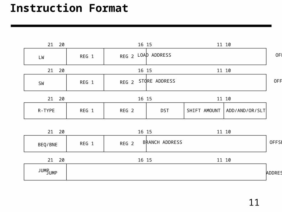
Instruction Format
31 26 25 21 20 16 15 11 10 6 5 0
JUMP JUMP ADDRESS
31 26 25 21 20 16 15 11 10 6 5 0
REG 1 REG 2BEQ/BNE BRANCH ADDRESS OFFSET
31 26 25 21 20 16 15 11 10 6 5 0
REG 1 REG 2SW STORE ADDRESS OFFSET
31 26 25 21 20 16 15 11 10 6 5 0
REG 1 REG 2LW LOAD ADDRESS OFFSET
31 26 25 21 20 16 15 11 10 6 5 0
REG 1 REG 2 DSTR-TYPE SHIFT AMOUNT ADD/AND/OR/SLT
12
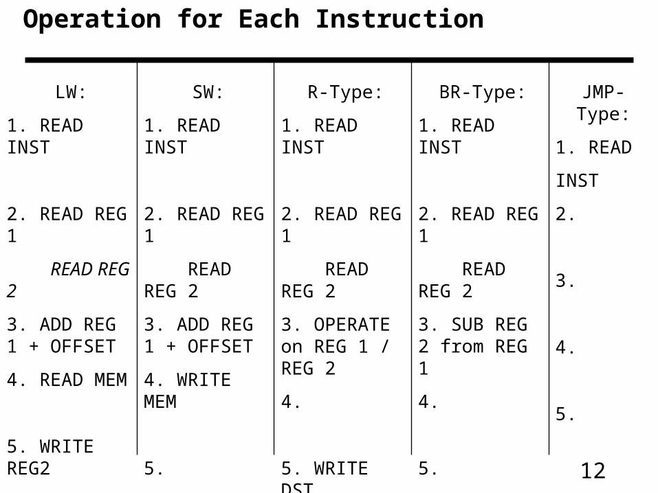
Operation for Each Instruction
LW:
1. READ INST
2. READ REG 1
READ REG 2
3. ADD REG 1 + OFFSET
4. READ MEM
5. WRITE REG2
SW:
1. READ INST
2. READ REG 1
READ REG 2
3. ADD REG 1 + OFFSET
4. WRITE MEM
5.
R-Type:
1. READ INST
2. READ REG 1
READ REG 2
3. OPERATE on REG 1 / REG 2
4.
5. WRITE DST
BR-Type:
1. READ INST
2. READ REG 1
READ REG 2
3. SUB REG 2 from REG 1
4.
5.
JMP-Type:
1. READ
INST
2.
3.
4.
5.
13
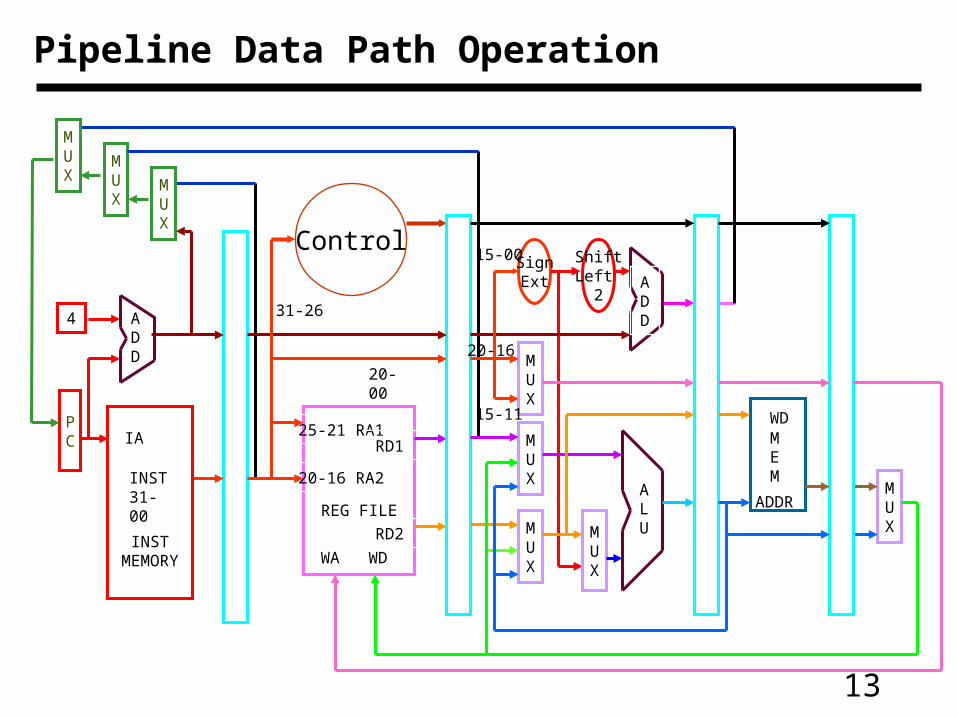
Pipeline Data Path Operation
PC
4 ADD
INSTMEMORY
IA
INST31-00
MUX
MUX
MUX
Control
20-00
31-26
REG FILE
25-21 RA1
20-16 RA2
RD1
RD2
WA WD
MUX
SignExt
ShiftLeft
2
MUX
MUX
MUX
20-16
15-11
ALU
ADD
15-00
MUX
MEM
WD
ADDR

14
Fetch Unit
PC
4 ADD
INSTMEMORY
IA
INST31-00
MUX
MUX
MUX
NPC
INST
Jump Address
Jump Register AddressBranch Address
15
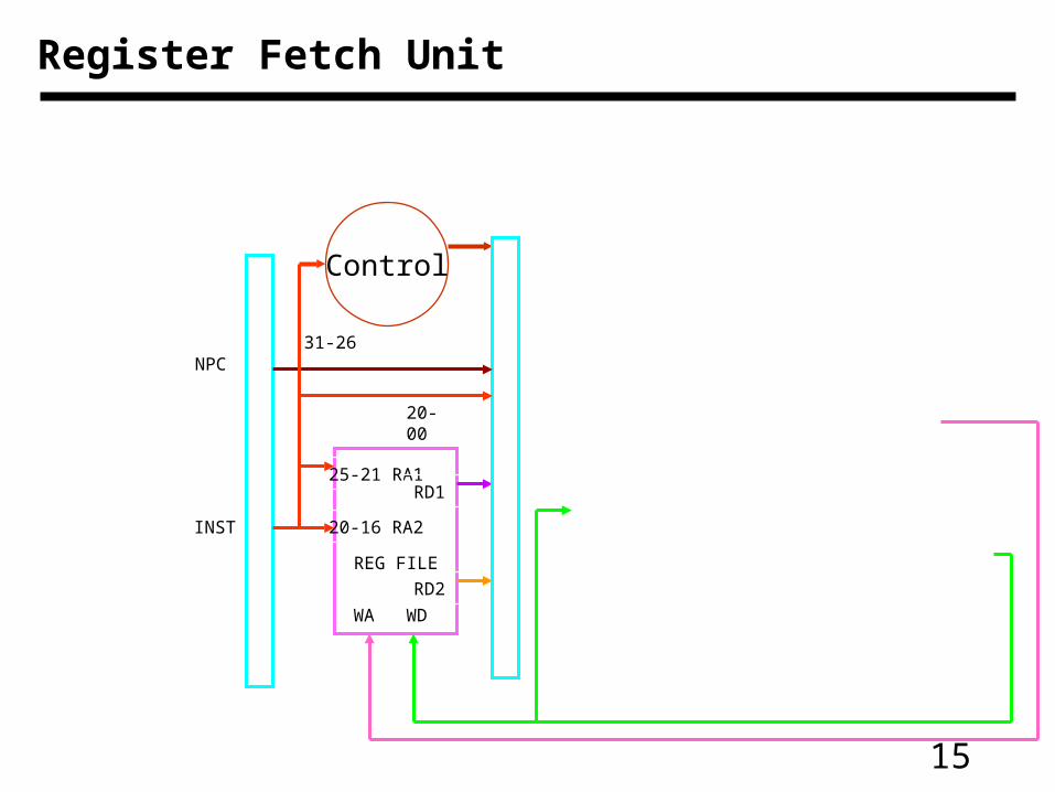
Register Fetch Unit
Control
20-00
31-26
REG FILE
25-21 RA1
20-16 RA2
RD1
RD2
WA WD
NPC
INST

16
ALU Operation and Branch Logic
MUX
SignExt
ShiftLeft
2
MUX
MUX
MUX
20-16
15-11
ALU
ADD
15-00
RD1
RD2
INST 20-00
Branch address
Reg Write Address
Write Data
ALU OUTPUT
17
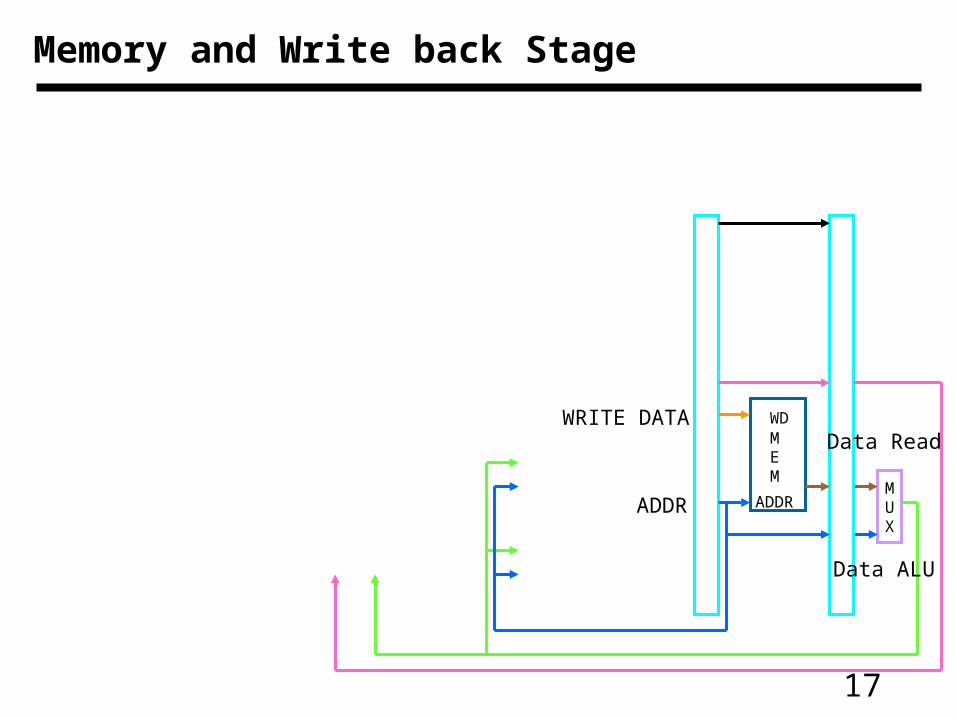
Memory and Write back Stage
MUX
MEM
WD
ADDR
WRITE DATA
ADDR
Data Read
Data ALU

18
Pipeline Data Path Operation
PC
4 ADD
INSTMEMORY
IA
INST31-00
MUX
MUX
MUX
Control
20-00
31-26
REG FILE
25-21 RA1
20-16 RA2
RD1
RD2
WA WD
MUX
SignExt
ShiftLeft
2
MUX
MUX
MUX
20-16
15-11
ALU
ADD
15-00
MUX
MEM
WD
ADDR
19
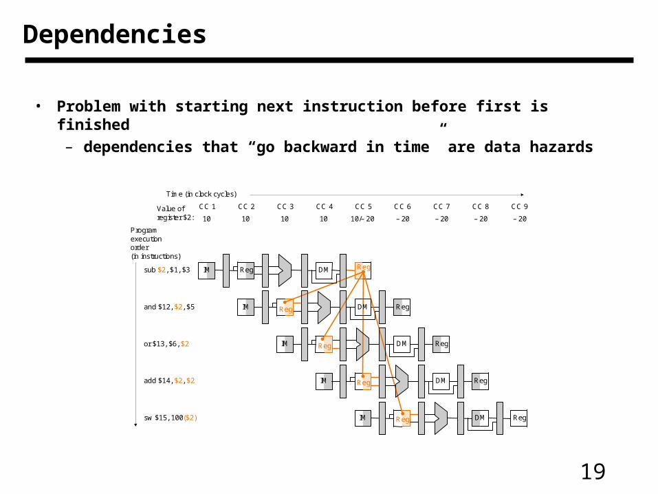
• Problem with starting next instruction before first is finished
– dependencies that “go backward in time” are data hazards
Dependencies
IM Reg
IM Reg
CC 1 CC 2 CC 3 CC 4 CC 5 CC 6
Time (in clock cycles)
sub $2, $1, $3
Programexecutionorder(in instructions)
and $12, $2, $5
IM Reg DM Reg
IM DM Reg
IM DM Reg
CC 7 CC 8 CC 9
10 10 10 10 10/– 20 – 20 – 20 – 20 – 20
or $13, $6, $2
add $14, $2, $2
sw $15, 100($2)
Value of register $2:
DM Reg
Reg
Reg
Reg
DM

20
• Consider the following program
add $t0, $t1, $t2
add $t1, $t0, $t3
and $t2, $t4, $t0
or $t3, $t1, $t0
slt $t4, $t2, $t3
• Problem with starting next instruction before first is finished– dependencies that “go backward in time” are data hazards
A program with data dependencies

21
Data Path Operation
C1 C2 C3 C4 C5 C6 C7 C8 C9
ALU
MUX
INSTFETCH
REGFILE
MUX
DATAMEMORY
ALU
MUX
INSTFETCH
REGFILE
MUX
DATAMEMORY
ALU
MUX
INSTFETCH
REGFILE
MUX
DATAMEMORY
ALU
MUX
INSTFETCH
REGFILE
MUX
DATAMEMORY
ALU
MUX
INSTFETCH
REGFILE
MUX
DATAMEMORY
add $t0, $t1, $t2
add $t1, $t0, $t3
and $t2, $t4, $t0
or $t3, $t1, $t0
slt $t4, $t2, $t3
22
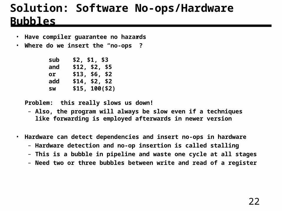
• Have compiler guarantee no hazards• Where do we insert the “no-ops” ?
sub $2, $1, $3and $12, $2, $5or $13, $6, $2add $14, $2, $2sw $15, 100($2)
Problem: this really slows us down!– Also, the program will always be slow even if a techniques like
forwarding is employed afterwards in newer version
• Hardware can detect dependencies and insert no-ops in hardware– Hardware detection and no-op insertion is called stalling– This is a bubble in pipeline and waste one cycle at all stages– Need two or three bubbles between write and read of a register
Solution: Software No-ops/Hardware Bubbles

23
Hazard Detection Unit
• Stall by letting an instruction that won’t write anything go forward
PCInstruction
memory
Registers
Mux
Mux
Mux
Control
ALU
EX
M
WB
M
WB
WB
ID/EX
EX/MEM
MEM/WB
Datamemory
Mux
Hazarddetection
unit
Forwardingunit
0
Mux
IF/ID
Inst
ruct
ion
ID/EX.MemRead
IF/I
DW
rite
PC
Wri
te
ID/EX.RegisterRt
IF/ID.RegisterRd
IF/ID.RegisterRt
IF/ID.RegisterRt
IF/ID.RegisterRs
RtRs
Rd
Rt EX/MEM.RegisterRd
MEM/WB.RegisterRd
24
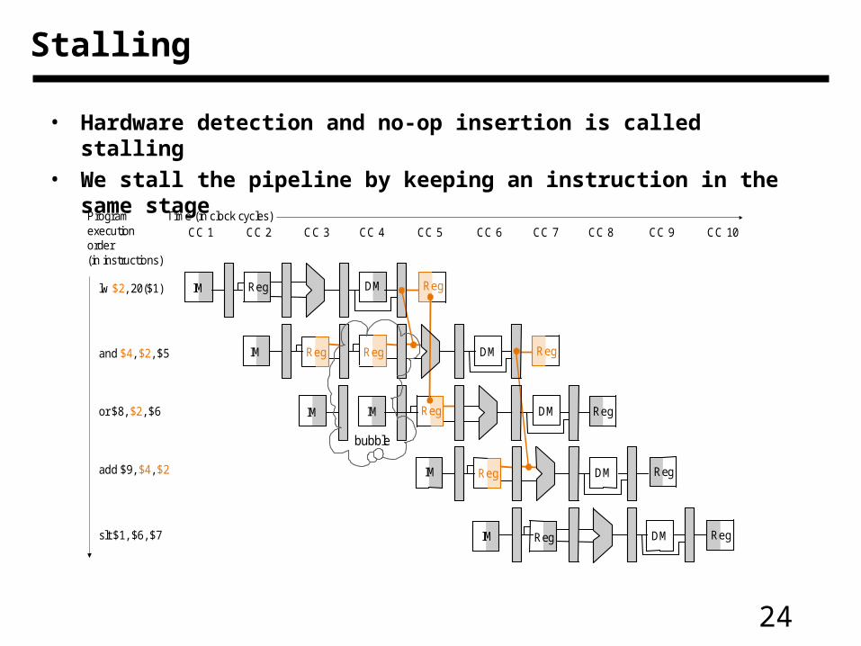
Stalling
• Hardware detection and no-op insertion is called stalling
• We stall the pipeline by keeping an instruction in the same stage
lw $2, 20($1)
Programexecutionorder(in instructions)
and $4, $2, $5
or $8, $2, $6
add $9, $4, $2
slt $1, $6, $7
Reg
IM
Reg
Reg
IM DM
CC 1 CC 2 CC 3 CC 4 CC 5 CC 6Time (in clock cycles)
IM Reg DM RegIM
IM DM Reg
IM DM Reg
CC 7 CC 8 CC 9 CC 10
DM Reg
RegReg
Reg
bubble

25
Stalled Operation (no write before read)
C1 C2 C3 C4 C5 C6 C7 C8 C9
ALU
MUX
INSTFETCH
REGFILE
MUX
DATAMEMORY
ALU
MUX
INSTFETCH
REGFILE
MUX
DATAMEMORY
ALU
MUX
INSTFETCH
REGFILE
MUX
DATAMEMORY
ALU
MUX
INSTFETCH
REGFILE
MUX
DATAMEMORY
ALU
MUX
INSTFETCH
REGFILE
MUX
DATAMEMORY
add $t0, $t1, $t2
add $t1, $t0, $t3
add $t1, $t0, $t3
add $t1, $t0, $t3
add $t1, $t0, $t3
26
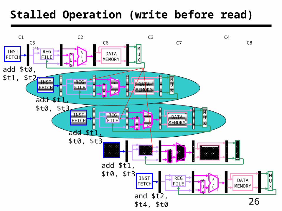
Stalled Operation (write before read)
C1 C2 C3 C4 C5 C6 C7 C8 C9
ALU
MUX
INSTFETCH
REGFILE
MUX
DATAMEMORY
ALU
MUX
INSTFETCH
REGFILE
MUX
DATAMEMORY
ALU
MUX
INSTFETCH
REGFILE
MUX
DATAMEMORY
ALU
MUX
INSTFETCH
REGFILE
MUX
DATAMEMORY
ALU
MUX
INSTFETCH
REGFILE
MUX
DATAMEMORY
add $t0, $t1, $t2
add $t1, $t0, $t3
add $t1, $t0, $t3
and $t2, $t4, $t0
add $t1, $t0, $t3

27
• EX hazard– If ((EX/MEM.RegWrite) and (EX/MEM.RegisterRd != 0) and
(EX/MEM.REgisterRd = ID/EX.RegisterRs)) ForwardA = 10– If ((EX/MEM.RegWrite) and (EX/MEM.RegisterRd != 0) and
(EX/MEM.RegisterRd = ID/EX.RegisterRt)) ForwardB = 10
• MEM hazard– If ((MEM/WB.RegWrite) and (MEM/WB.REgisterRd != 0) and
(MEM/WB.REgisterRd = ID/EX.RegisterRs)) ForwardA = 01– If ((MEM/WB.RegWrite) and (MEM/WB.REgisterRd != 0) and
(MEM/WB.REgisterRd = ID/EX.RegisterRt)) ForwardB = 10
• In case of lw followed by a sw instruction, forwarding will not work. This is because data in MEM stage are still being read– Plan on adding forwarding in MEM stage of put a
stall/bubble• In case of lw followed by an instruction that uses the value
– One has to add an stall
Detecting Hazards for Forwarding

28
• Use temporary results, don’t wait for them to be written
– register file forwarding to handle read/write to same register
– ALU forwarding
– May also need forwarding to memory (think!!)
Forwarding
what if this $2 was $13?
IM Reg
IM Reg
CC 1 CC 2 CC 3 CC 4 CC 5 CC 6
Time (in clock cycles)
sub $2, $1, $3
Programexecution order(in instructions)
and $12, $2, $5
IM Reg DM Reg
IM DM Reg
IM DM Reg
CC 7 CC 8 CC 9
10 10 10 10 10/– 20 – 20 – 20 – 20 – 20
or $13, $6, $2
add $14, $2, $2
sw $15, 100($2)
Value of register $2 :
DM Reg
Reg
Reg
Reg
X X X – 20 X X X X XValue of EX/MEM :X X X X – 20 X X X XValue of MEM/WB :
DM

29
Forwarding
PCInstruction
memory
Registers
Mux
Mux
Control
ALU
EX
M
WB
M
WB
WB
ID/EX
EX/MEM
MEM/WB
Datamemory
Mux
Forwardingunit
IF/ID
Inst
ruct
ion
Mux
RdEX/MEM.RegisterRd
MEM/WB.RegisterRd
Rt
Rt
Rs
IF/ID.RegisterRd
IF/ID.RegisterRt
IF/ID.RegisterRt
IF/ID.RegisterRs
30
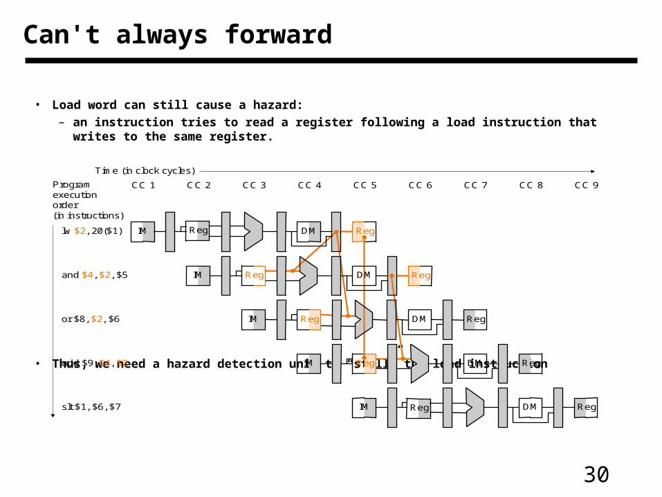
• Load word can still cause a hazard:
– an instruction tries to read a register following a load instruction that writes to the same register.
• Thus, we need a hazard detection unit to “stall” the load instruction
Can't always forward
Reg
IM
Reg
Reg
IM
CC 1 CC 2 CC 3 CC 4 CC 5 CC 6
Time (in clock cycles)
lw $2, 20($1)
Programexecutionorder(in instructions)
and $4, $2, $5
IM Reg DM Reg
IM DM Reg
IM DM Reg
CC 7 CC 8 CC 9
or $8, $2, $6
add $9, $4, $2
slt $1, $6, $7
DM Reg
Reg
Reg
DM
31
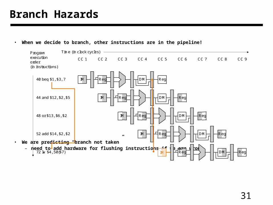
• When we decide to branch, other instructions are in the pipeline!
• We are predicting “branch not taken”– need to add hardware for flushing instructions if we are wrong
Branch Hazards
Reg
Reg
CC 1
Time (in clock cycles)
40 beq $1, $3, 7
Programexecutionorder(in instructions)
IM Reg
IM DM
IM DM
IM DM
DM
DM Reg
Reg Reg
Reg
Reg
RegIM
44 and $12, $2, $5
48 or $13, $6, $2
52 add $14, $2, $2
72 lw $4, 50($7)
CC 2 CC 3 CC 4 CC 5 CC 6 CC 7 CC 8 CC 9
Reg
32
Improving Performance
• Try and avoid stalls! E.g., reorder these instructions:
lw $t0, 0($t1)lw $t2, 4($t1)sw $t2, 0($t1)sw $t0, 4($t1)
• Add a “branch delay slot”
– the next instruction after a branch is always executed
– rely on compiler to “fill” the slot with something useful
• Superscalar: start more than one instruction in the same cycle
33
Other Issues in Pipelines
• Exceptions
– Errors in ALU for arithmetic instructions
– Memory non-availability
• Exceptions lead to a jump in a program
• However, the current PC value must be saved so that the program can return to it back for recoverable errors
• Multiple exception can occur in a pipeline
• Preciseness of exception location is important in some cases
• I/O exceptions are handled in the same manner
34
Handling Branches
• Branch Prediction
– Usually we may simply assume that branch is not taken
– If it is taken, then we flush the pipeline
• Clear control signals for instruction following branch
• Delayed branch
– Fill instructions that need to be executed even if branch occur
– If none available fill NOOPs
• Reduce delay in resolving branches
– Compare at register stage
– Branch prediction table
• PC value (for branch) and next address
• One or two bits to store what should be prediction

35
Two State vs Four State Branch Prediction
• Two state model
• Four State Model
PredictTaken
Predict Not
TakenTakenNot Taken
Not TakenTaken
PredictNot
Taken
Predict Not
TakenTaken
Not Taken
Not Taken
Taken
PredictTaken
Predict TakenTaken
Not Taken
Not TakenTaken
36
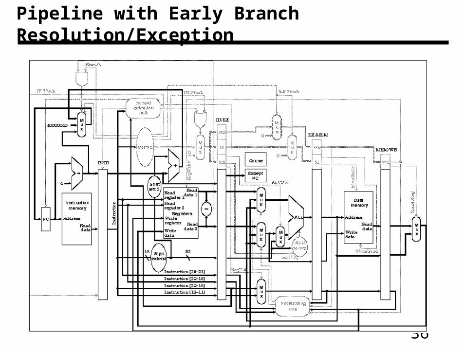
Pipeline with Early Branch Resolution/Exception
37
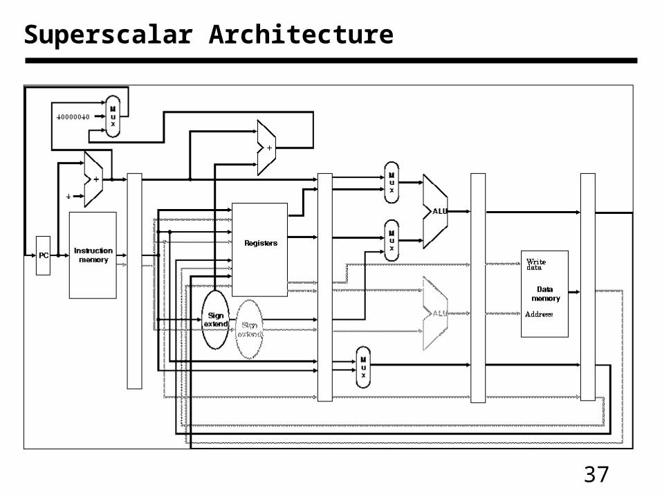
Superscalar Architecture
38
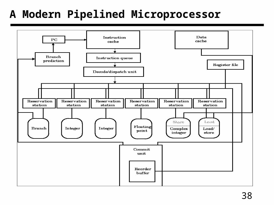
A Modern Pipelined Microprocessor
39
Important Facts to Remember
• Pipelined processors divide the execution in multiple steps
• However pipeline hazards reduce performance
– Structural, data, and control hazard
• Data forwarding helps resolve data hazards
– But all hazards cannot be resolved
– Some data hazards require bubble or noop insertion
• Effects of control hazard reduced by branch prediction
– Predict always taken, delayed slots, branch prediction table
– Structural hazards are resolved by duplicating resources

40
• We have 5 stages. What needs to be controlled in each stage?– Instruction Fetch and PC Increment– Instruction Decode / Register Fetch– Execution– Memory Stage– Write Back
• How would control be handled in an automobile plant?– a fancy control center telling everyone what to do?– should we use a finite state machine?
Pipeline control
41
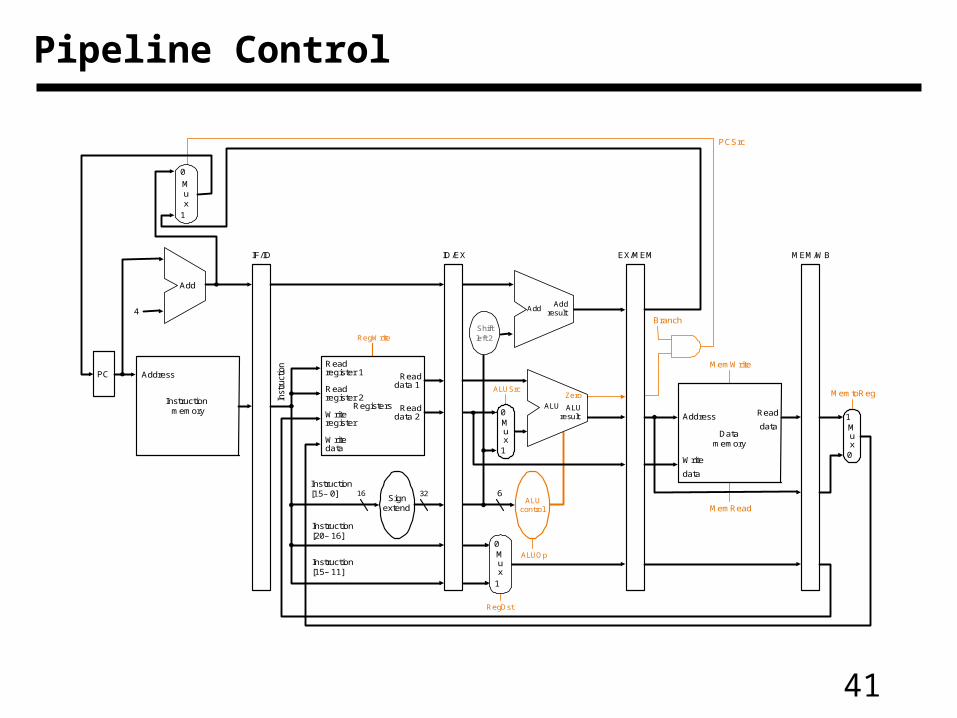
Pipeline Control
PC
Instructionmemory
Address
Inst
ruct
ion
Instruction[20– 16]
MemtoReg
ALUOp
Branch
RegDst
ALUSrc
4
16 32Instruction[15– 0]
0
0Registers
Writeregister
Writedata
Readdata 1
Readdata 2
Readregister 1
Readregister 2
Signextend
Mux
1Write
data
Read
data Mux
1
ALUcontrol
RegWrite
MemRead
Instruction[15– 11]
6
IF/ID ID/EX EX/MEM MEM/WB
MemWrite
Address
Datamemory
PCSrc
Zero
AddAdd
result
Shiftleft 2
ALUresult
ALU
Zero
Add
0
1
Mux
0
1
Mux

42
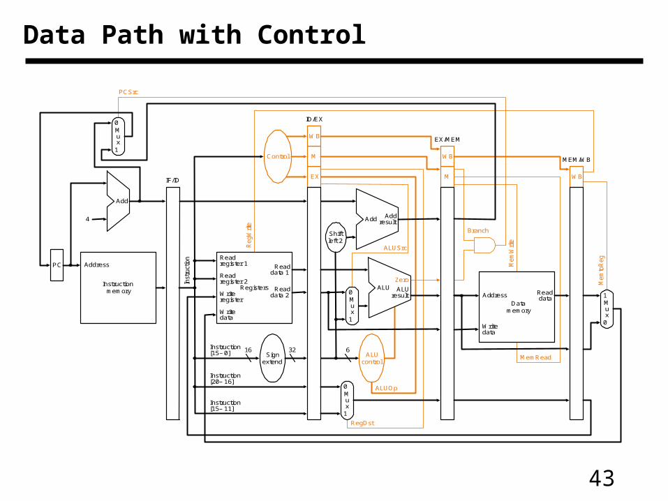
• Pass control signals along just like the data
Pipeline Control
Execution/Address Calculation stage control lines
Memory access stage control lines
Write-back stage control
lines
InstructionReg Dst
ALU Op1
ALU Op0
ALU Src Branch
Mem Read
Mem Write
Reg write
Mem to Reg
R-format 1 1 0 0 0 0 0 1 0lw 0 0 0 1 0 1 0 1 1sw X 0 0 1 0 0 1 0 Xbeq X 0 1 0 1 0 0 0 X
Control
EX
M
WB
M
WB
WB
IF/ID ID/EX EX/MEM MEM/WB
Instruction
43
Data Path with Control
PC
Instructionmemory
Inst
ruct
ion
Add
Instruction[20– 16]
Mem
toR
eg
ALUOp
Branch
RegDst
ALUSrc
4
16 32Instruction[15– 0]
0
0
Mux
0
1
Add Addresult
RegistersWriteregister
Writedata
Readdata 1
Readdata 2
Readregister 1
Readregister 2
Signextend
Mux
1
ALUresult
Zero
Writedata
Readdata
Mux
1
ALUcontrol
Shiftleft 2
RegW
rite
MemRead
Control
ALU
Instruction[15– 11]
6
EX
M
WB
M
WB
WBIF/ID
PCSrc
ID/EX
EX/MEM
MEM/WB
Mux
0
1
Mem
Writ
e
AddressData
memory
Address
44
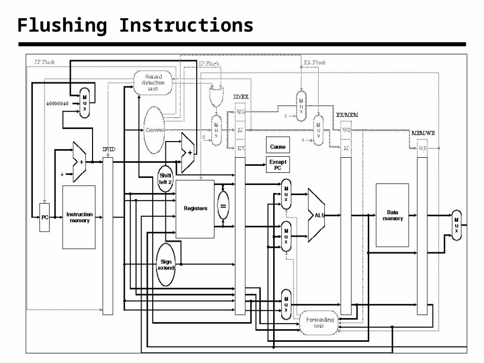
Flushing Instructions
Related Documents