1 Outline •Standards Organisations •Interface Standards The RS-232-C Standard RS-449, RS-422-A, RS-423-A USB and FireWire

1 Outline Standards Organisations Interface Standards The RS-232-C Standard RS-449, RS-422-A, RS-423-A USB and FireWire.
Dec 20, 2015
Welcome message from author
This document is posted to help you gain knowledge. Please leave a comment to let me know what you think about it! Share it to your friends and learn new things together.
Transcript
1
Outline
•Standards Organisations
•Interface Standards
The RS-232-C Standard
RS-449, RS-422-A, RS-423-A
USB and FireWire

2
Standards Organisations
ISO: International Organisation for Standards. It is comprised by national standards organisations from all countries.
ANSI: American National Standards Institute. It works under ISO.
Standardisation is required to achieve compatibility among different communications hardware and software produced by different companies.
IEEE: Institute of Electrical Electronic Engineers (e.g., IEEE 802)
3
Standards Organisations
ITU: International Telecommunications Union. Before 1992 ITU had a sub-group, CCITT (Comité Consultatif International Téléphonique et Télégraphique), to act as a standardisation group. CCITT does not exist anymore. ITU has assumed the task.
IETF: Internet Engineering Task Force. Main standardisation organisation for Internet.
EIA: Electronics Industries Association.
4
RS-232-C Interface
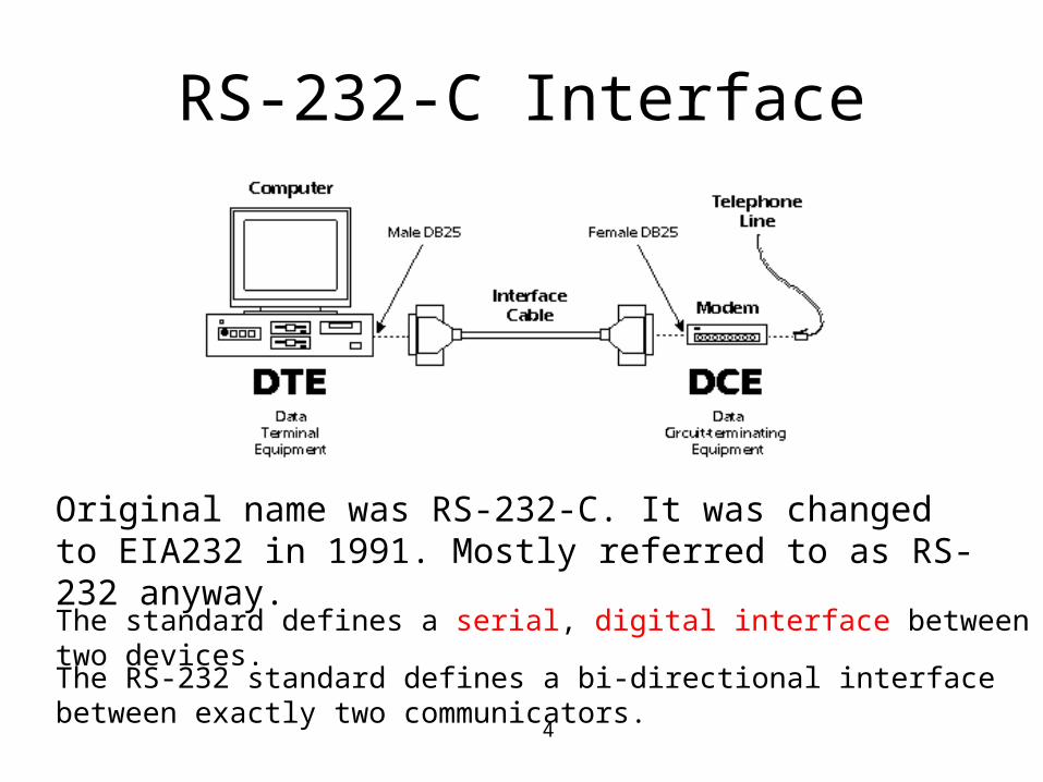
Original name was RS-232-C. It was changed to EIA232 in 1991. Mostly referred to as RS-232 anyway. The standard defines a serial, digital interface between two devices. The RS-232 standard defines a bi-directional interface between exactly two communicators.
5
RS-232-C Interface
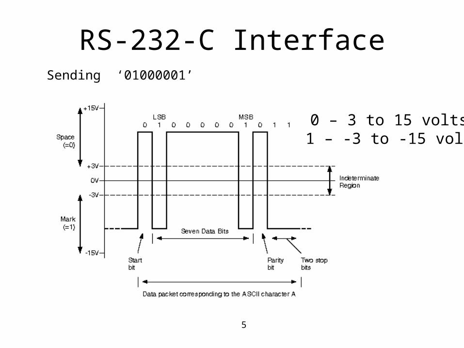
0 – 3 to 15 volts 1 – -3 to -15 volts
Sending ‘01000001’
6
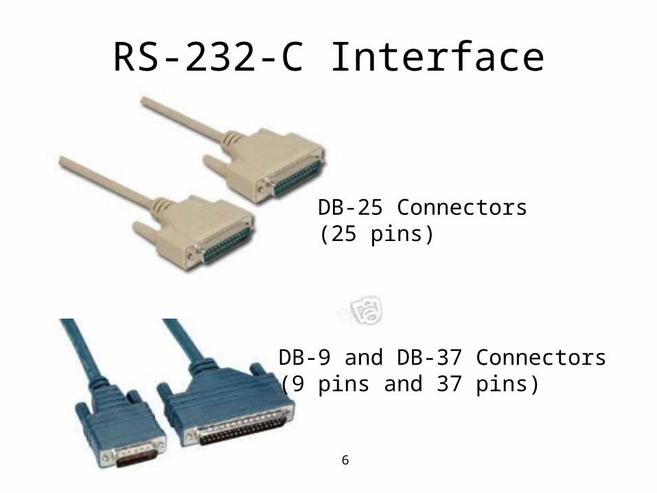
RS-232-C Interface
DB-25 Connectors(25 pins)
DB-9 and DB-37 Connectors(9 pins and 37 pins)
7
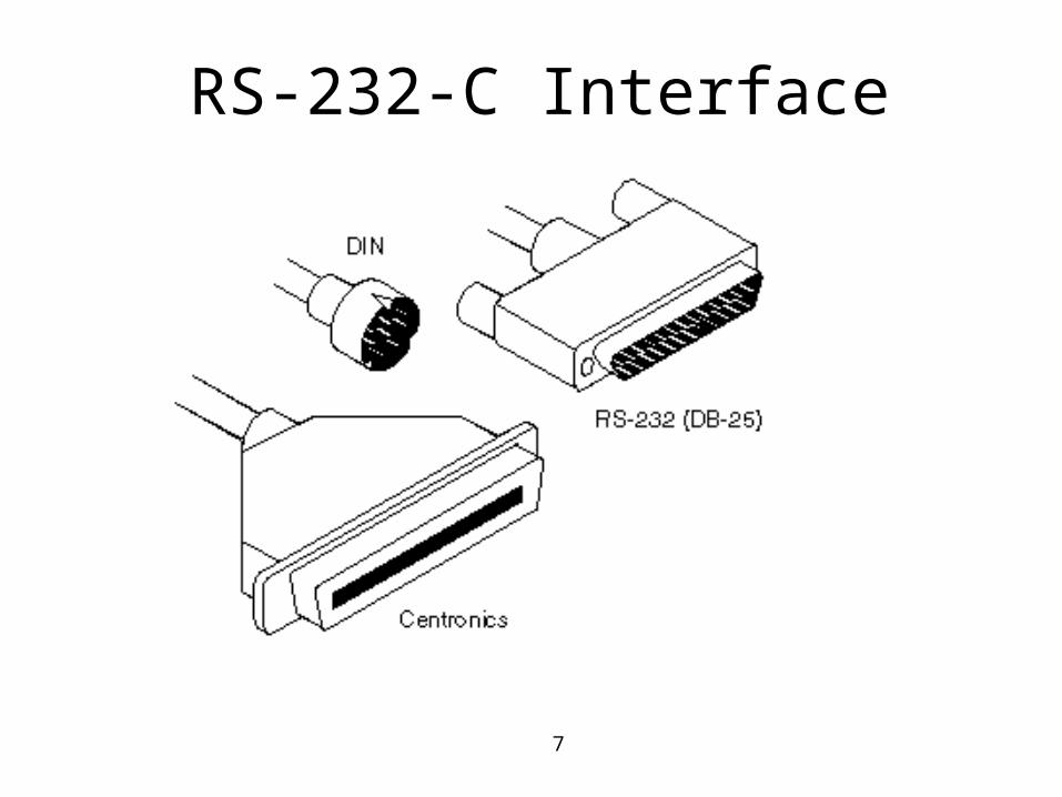
RS-232-C Interface
8
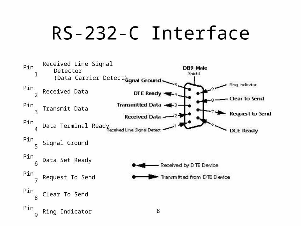
RS-232-C Interface
Pin 1Received Line Signal Detector
(Data Carrier Detect)
Pin 2 Received Data
Pin 3 Transmit Data
Pin 4 Data Terminal Ready
Pin 5 Signal Ground
Pin 6 Data Set Ready
Pin 7 Request To Send
Pin 8 Clear To Send
Pin 9 Ring Indicator
9
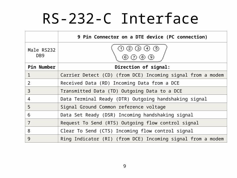
9 Pin Connector on a DTE device (PC connection)
Male RS232 DB9
Pin Number Direction of signal:
1 Carrier Detect (CD) (from DCE) Incoming signal from a modem
2 Received Data (RD) Incoming Data from a DCE
3 Transmitted Data (TD) Outgoing Data to a DCE
4 Data Terminal Ready (DTR) Outgoing handshaking signal
5 Signal Ground Common reference voltage
6 Data Set Ready (DSR) Incoming handshaking signal
7 Request To Send (RTS) Outgoing flow control signal
8 Clear To Send (CTS) Incoming flow control signal
9 Ring Indicator (RI) (from DCE) Incoming signal from a modem
RS-232-C Interface
10
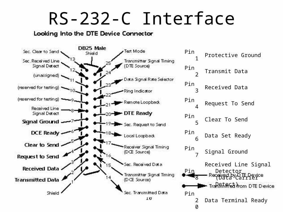
RS-232-C Interface
Pin 1 Protective Ground
Pin 2 Transmit Data
Pin 3 Received Data
Pin 4 Request To Send
Pin 5 Clear To Send
Pin 6 Data Set Ready
Pin 7 Signal Ground
Pin 8Received Line Signal Detector
(Data Carrier Detect)
Pin 20 Data Terminal Ready
Pin 22 Ring Indicator
11
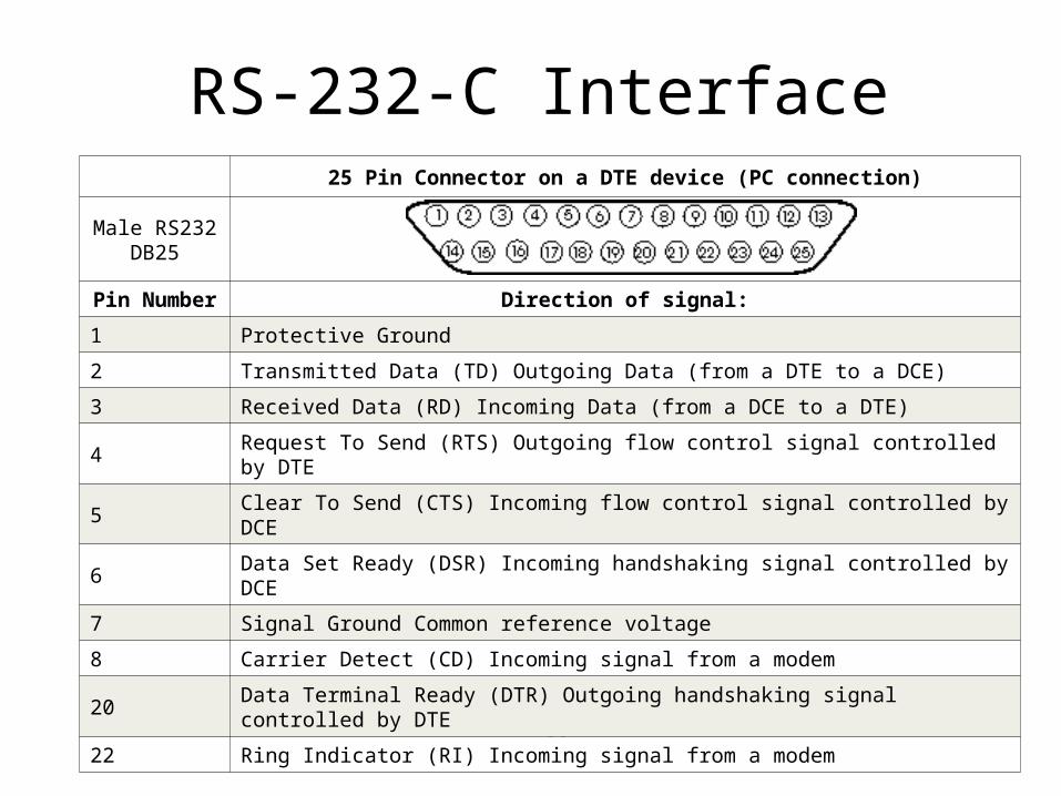
25 Pin Connector on a DTE device (PC connection)
Male RS232 DB25
Pin Number Direction of signal:
1 Protective Ground
2 Transmitted Data (TD) Outgoing Data (from a DTE to a DCE)
3 Received Data (RD) Incoming Data (from a DCE to a DTE)
4 Request To Send (RTS) Outgoing flow control signal controlled by DTE
5 Clear To Send (CTS) Incoming flow control signal controlled by DCE
6 Data Set Ready (DSR) Incoming handshaking signal controlled by DCE
7 Signal Ground Common reference voltage
8 Carrier Detect (CD) Incoming signal from a modem
20 Data Terminal Ready (DTR) Outgoing handshaking signal controlled by DTE
22 Ring Indicator (RI) Incoming signal from a modem
RS-232-C Interface
12
RS-232-C Interface
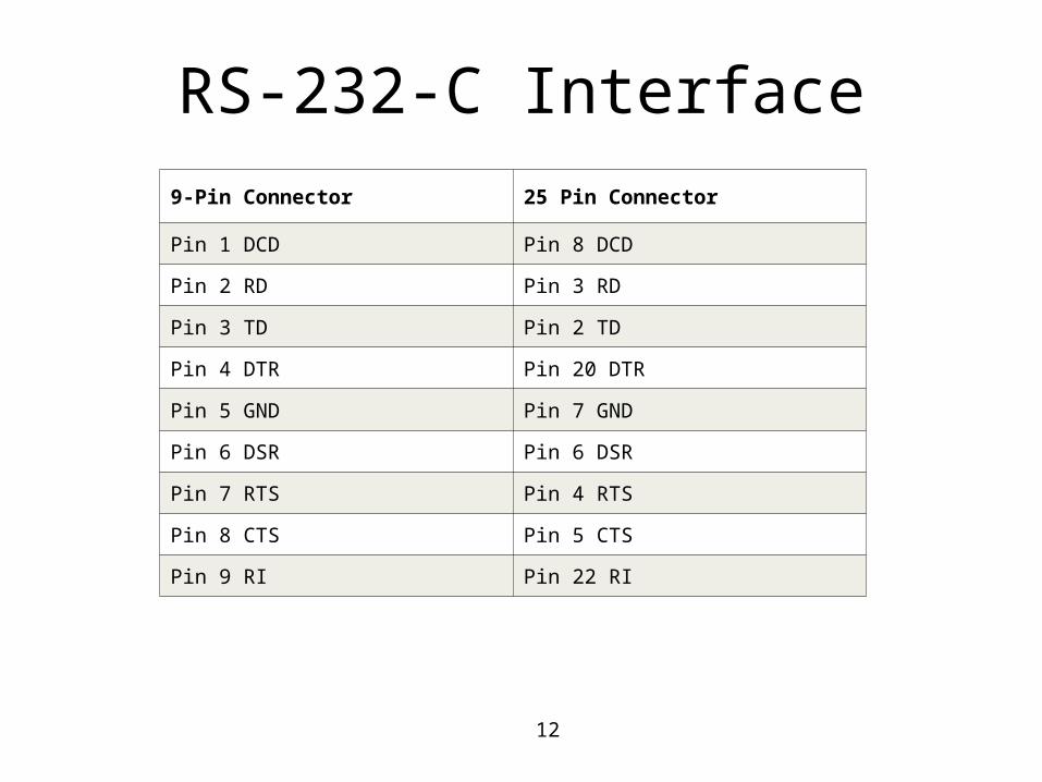
9-Pin Connector 25 Pin Connector
Pin 1 DCD Pin 8 DCD
Pin 2 RD Pin 3 RD
Pin 3 TD Pin 2 TD
Pin 4 DTR Pin 20 DTR
Pin 5 GND Pin 7 GND
Pin 6 DSR Pin 6 DSR
Pin 7 RTS Pin 4 RTS
Pin 8 CTS Pin 5 CTS
Pin 9 RI Pin 22 RI
13
14
15
16
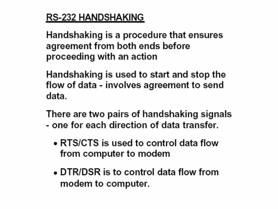
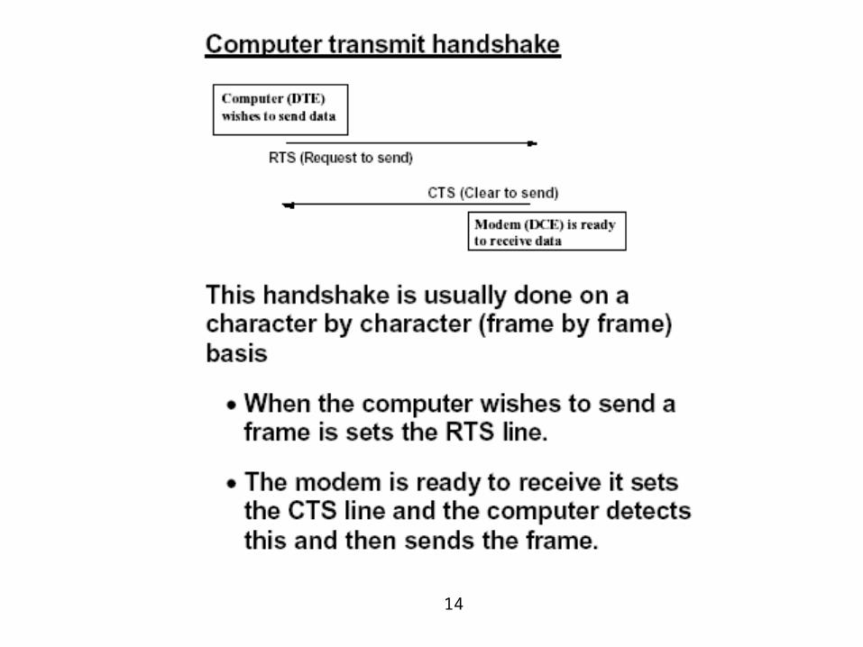
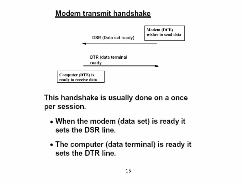
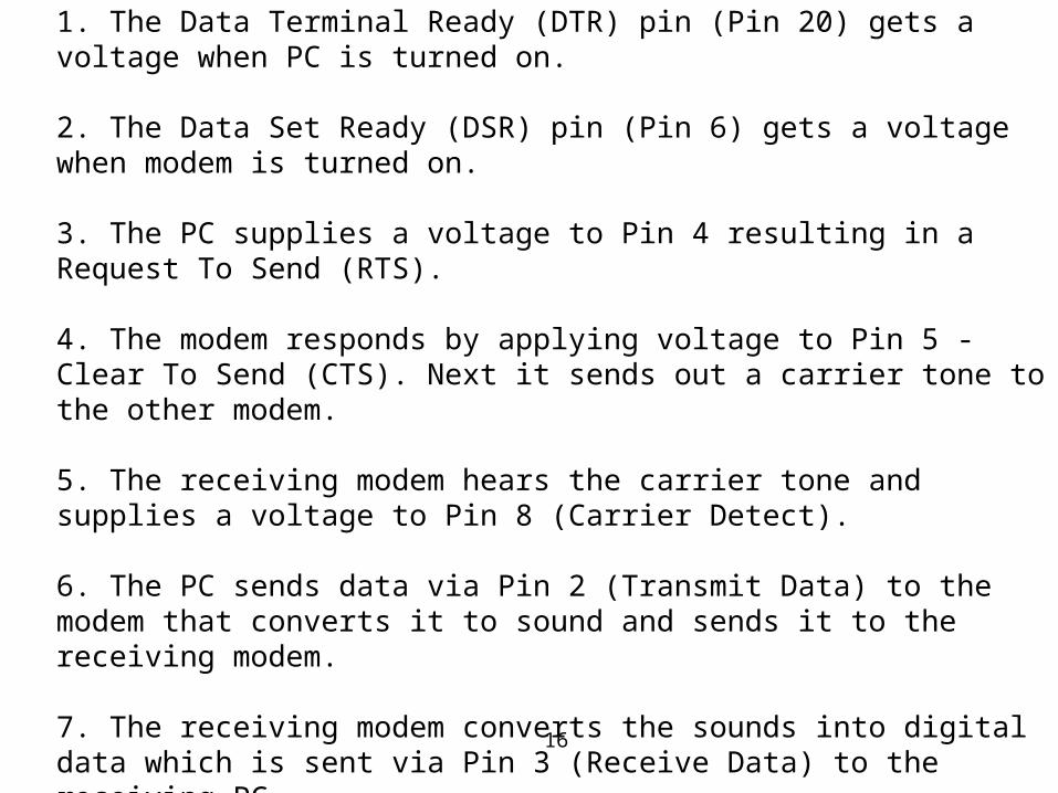
RS-232 Handshaking
1. The Data Terminal Ready (DTR) pin (Pin 20) gets a voltage when PC is turned on. 2. The Data Set Ready (DSR) pin (Pin 6) gets a voltage when modem is turned on. 3. The PC supplies a voltage to Pin 4 resulting in a Request To Send (RTS). 4. The modem responds by applying voltage to Pin 5 - Clear To Send (CTS). Next it sends out a carrier tone to the other modem. 5. The receiving modem hears the carrier tone and supplies a voltage to Pin 8 (Carrier Detect). 6. The PC sends data via Pin 2 (Transmit Data) to the modem that converts it to sound and sends it to the receiving modem. 7. The receiving modem converts the sounds into digital data which is sent via Pin 3 (Receive Data) to the receiving PC.

17
18
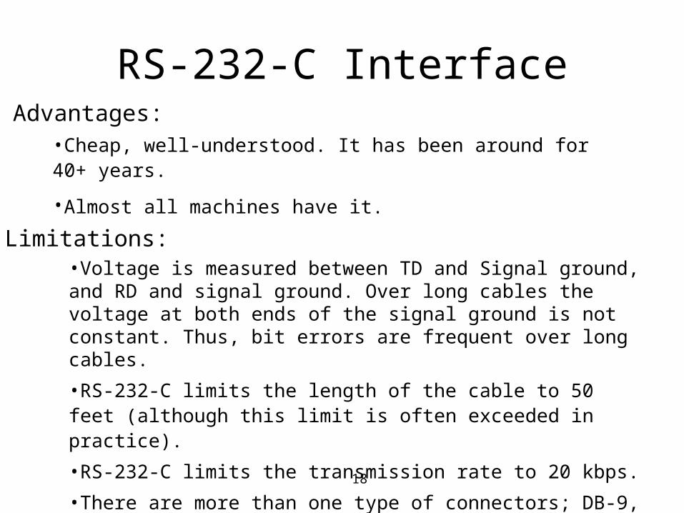
RS-232-C InterfaceAdvantages:
•Cheap, well-understood. It has been around for 40+ years.
•Almost all machines have it.
Limitations:•Voltage is measured between TD and Signal ground, and RD and signal ground. Over long cables the voltage at both ends of the signal ground is not constant. Thus, bit errors are frequent over long cables.
•RS-232-C limits the length of the cable to 50 feet (although this limit is often exceeded in practice).
•RS-232-C limits the transmission rate to 20 kbps.
•There are more than one type of connectors; DB-9, 25, and 37
19
RS-449, RS-423-A, RS-422-A• They are all improvements to RS-232-C. (page:67-68, Beyda)
• RS-449 is the “parent standard” that specifies the functional and
mechanical characteristics of the interconnection between DTE and
complying EIA signaling standards RS-422 and RS-423.
Two pins – Category I signals; (RS-422A) : Balanced Transmission
Single pin – Category II signals (RS-423A) : Unbalanced Transmission
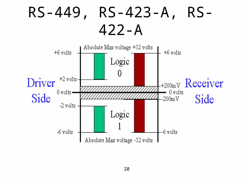
• While RS-232 uses signals with reference to ground, RS449
receivers look for the difference between two wires – less prone to
noise problem.
• RS-422 supports multipoint connections whereas RS-423 supports
only point-to-point connections.
20
RS-449, RS-423-A, RS-422-A
21
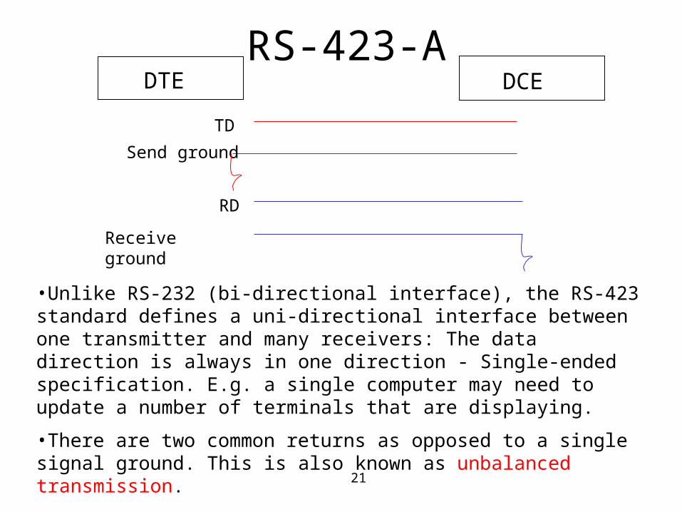
RS-423-ADTE DCE
TD
RD
Send ground
Receive ground
•Unlike RS-232 (bi-directional interface), the RS-423 standard defines a uni-directional interface between one transmitter and many receivers: The data direction is always in one direction - Single-ended specification. E.g. a single computer may need to update a number of terminals that are displaying.
•There are two common returns as opposed to a single signal ground. This is also known as unbalanced transmission.
•RS-423 allows for distances up to 4000 feet but limits data rates to only 100 kb/sec for a maximum of ten receivers.
22
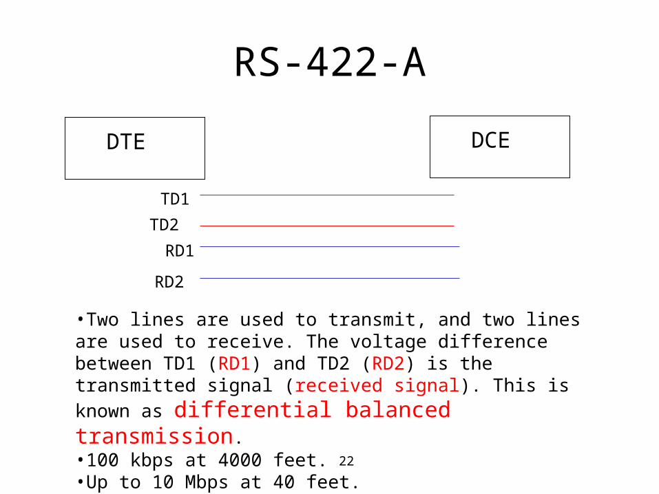
RS-422-A
DTE DCE
TD1
RD1
TD2
RD2
•Two lines are used to transmit, and two lines are used to receive. The voltage difference between TD1 (RD1) and TD2 (RD2) is the transmitted signal (received signal). This is known as differential balanced transmission.•100 kbps at 4000 feet.•Up to 10 Mbps at 40 feet.
23
What do they mean by Balanced line? How does it work?
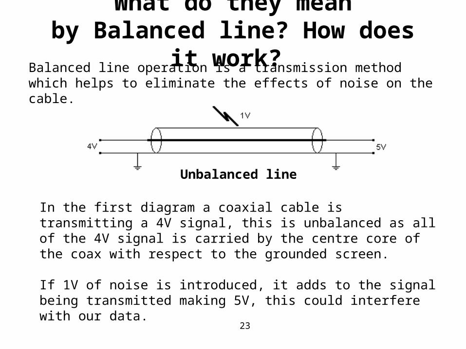
Balanced line operation is a transmission method which helps to eliminate the effects of noise on the cable.
In the first diagram a coaxial cable is transmitting a 4V signal, this is unbalanced as all of the 4V signal is carried by the centre core of the coax with respect to the grounded screen.
If 1V of noise is introduced, it adds to the signal being transmitted making 5V, this could interfere with our data.
Unbalanced line
24
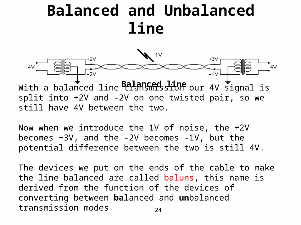
Balanced line
With a balanced line transmission our 4V signal is split into +2V and -2V on one twisted pair, so we still have 4V between the two.
Now when we introduce the 1V of noise, the +2V becomes +3V, and the -2V becomes -1V, but the potential difference between the two is still 4V.
The devices we put on the ends of the cable to make the line balanced are called baluns, this name is derived from the function of the devices of converting between balanced and unbalanced transmission modes
Balanced and Unbalanced line
25
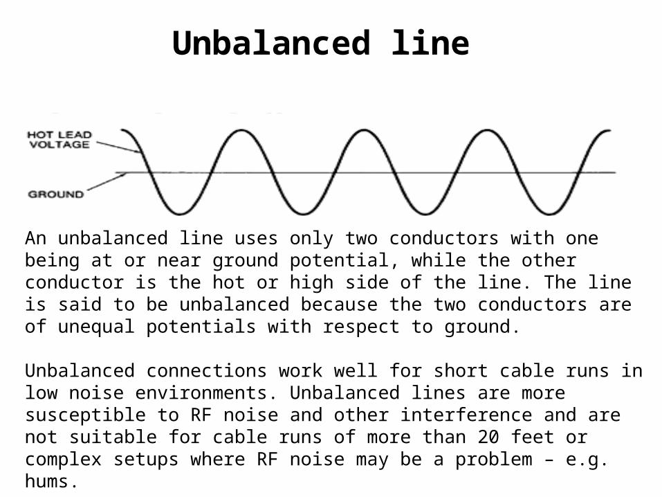
Unbalanced line
An unbalanced line uses only two conductors with one being at or near ground potential, while the other conductor is the hot or high side of the line. The line is said to be unbalanced because the two conductors are of unequal potentials with respect to ground.
Unbalanced connections work well for short cable runs in low noise environments. Unbalanced lines are more susceptible to RF noise and other interference and are not suitable for cable runs of more than 20 feet or complex setups where RF noise may be a problem – e.g. hums.
26
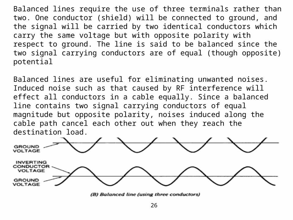
Balanced line Balanced lines require the use of three terminals rather than two. One conductor (shield) will be connected to ground, and the signal will be carried by two identical conductors which carry the same voltage but with opposite polarity with respect to ground. The line is said to be balanced since the two signal carrying conductors are of equal (though opposite) potential
Balanced lines are useful for eliminating unwanted noises. Induced noise such as that caused by RF interference will effect all conductors in a cable equally. Since a balanced line contains two signal carrying conductors of equal magnitude but opposite polarity, noises induced along the cable path cancel each other out when they reach the destination load.
27
Balanced and Unbalanced line
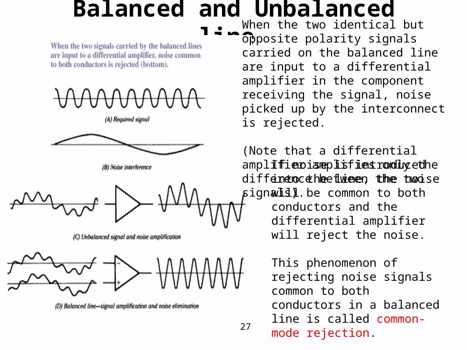
When the two identical but opposite polarity signals carried on the balanced line are input to a differential amplifier in the component receiving the signal, noise picked up by the interconnect is rejected.
(Note that a differential amplifier amplifies only the difference between the two signals).
If noise is introduced into the line, the noise will be common to both conductors and the differential amplifier will reject the noise.
This phenomenon of rejecting noise signals common to both conductors in a balanced line is called common-mode rejection.
28
The RS232 standard had some problems: •The data transmission rate was limited to 20 kbps. •The distance for transmission is limited to 50 ft. •The standard does not specify a connector, which led to some 25-pin designs not compatible with each other. •Only one conductor per circuit is used, with only one signal return for both directions of transmission. •The interface uses unbalanced transmitters and receivers (unbalanced circuit is less desirable (relative to performance) than a balanced circuit). •The interface can generate considerable crosstalk among its component signals. •The overall interface design is for discrete component technology.
The RS449 standards had to achieve the following goals: •Maintain compatibility with the old RS-232-C. •Support a higher signaling rate bandwidth over longer distances than the RS-232-C. •Resolve the mechanical interface problems that were caused from the lack of connector specifications in the old standard (9, 25, 37 pins). – standard 37 pins throughout. •Improve the electrical characteristics of the interface by providing for balanced circuits.
29
USB (Universal Serial Bus) Interface
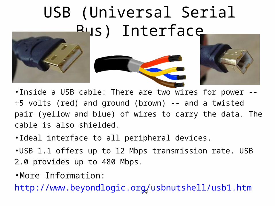
•Inside a USB cable: There are two wires for power -- +5 volts (red) and ground (brown) -- and a twisted pair (yellow and blue) of wires to carry the data. The cable is also shielded.
•Ideal interface to all peripheral devices.
•USB 1.1 offers up to 12 Mbps transmission rate. USB 2.0 provides up to 480 Mbps.
•More Information: http://www.beyondlogic.org/usbnutshell/usb1.htm
30
USB (Universal Serial Bus) Interface
•It is expected to replace parallel and serial ports.
•Power lines are to provide power for peripheral devices.
•One USB Bus can support up to 127 devices.
•Supports plug-n-play, and hot-plugging.
•The computer can guarantee bandwidth by reserving time slots in a 1500-byte frame every millisecond. 10 % bandwidth is reserved for control signaling.
•Supports real-time devices such as video cameras
•Cable length is up to 5 meters.
•Allows device-to-host connection only.
31
IEEE 1394 (FireWire) Interface
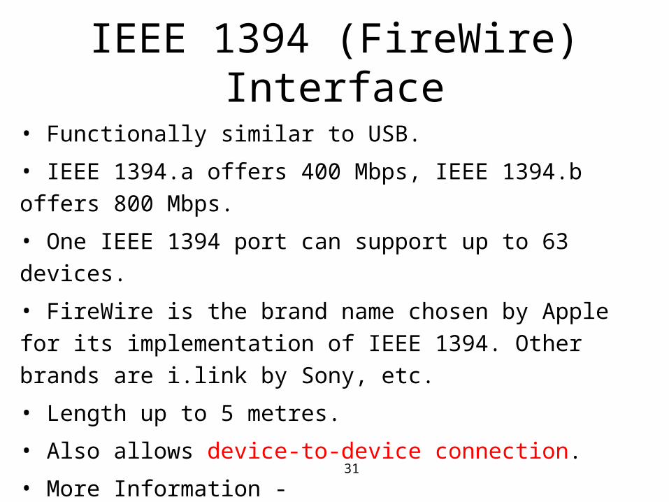
• Functionally similar to USB.
• IEEE 1394.a offers 400 Mbps, IEEE 1394.b offers 800 Mbps.
• One IEEE 1394 port can support up to 63 devices.
• FireWire is the brand name chosen by Apple for its implementation
of IEEE 1394. Other brands are i.link by Sony, etc.
• Length up to 5 metres.
• Also allows device-to-device connection.
• More Information - http://firewirestuff.com/whatis.html or
http://developer.apple.com/devicedrivers/firewire/index.html
32
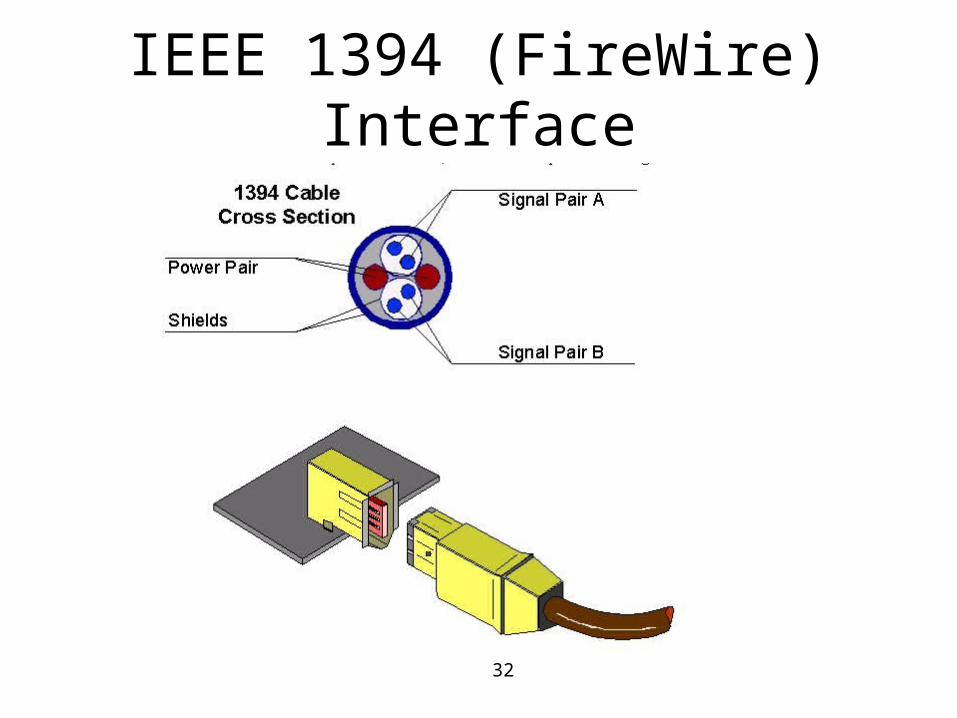
IEEE 1394 (FireWire) Interface
33
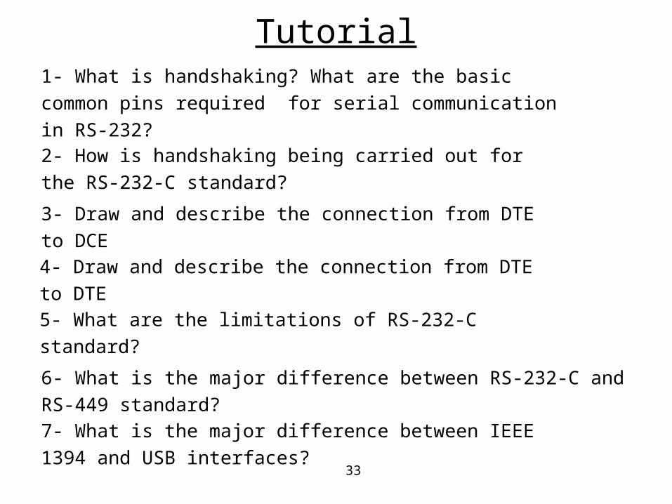
1- What is handshaking? What are the basic common pins required
for serial communication in RS-232?
5- What are the limitations of RS-232-C standard?
3- Draw and describe the connection from DTE to DCE
2- How is handshaking being carried out for the RS-232-C standard?
4- Draw and describe the connection from DTE to DTE
6- What is the major difference between RS-232-C and RS-449 standard?
7- What is the major difference between IEEE 1394 and USB
interfaces?
Tutorial
Related Documents