1 of 25 1 of 22 Blind-Spot Experiment Draw an image similar to that below on a piece of paper (the dot and cross are about 6 inches apart) Close your right eye and focus on the cross with your left eye Hold the image about 20 inches away from your face and move it slowly towards you The dot should disappear!

1 of 25 1 of 22 Blind-Spot Experiment Draw an image similar to that below on a piece of paper (the dot and cross are about 6 inches apart) Close your right.
Dec 19, 2015
Welcome message from author
This document is posted to help you gain knowledge. Please leave a comment to let me know what you think about it! Share it to your friends and learn new things together.
Transcript
1of25
1of22 Blind-Spot ExperimentDraw an image similar to that below on a piece of paper (the dot and cross are about 6 inches apart)
Close your right eye and focus on the cross with your left eye
Hold the image about 20 inches away from your face and move it slowly towards you
The dot should disappear!

2of25
2of22
Mobile Robotics:7. Vision 2
Dr. B
rian Mac N
amee (w
ww
.comp.dit.ie/bm
acnamee)

4of25
4of22 Acknowledgments
These notes are based (heavily) on those provided by the authors to accompany “Introduction to Autonomous Mobile Robots” by Roland Siegwart and Illah R. Nourbakhsh
More information about the book is available at:http://autonomousmobilerobots.epfl.ch/
The book can be bought at:The MIT Press and Amazon.com

5of25
5of22 Today’s LectureToday we will have a quick tour of some of the uses of vision sensors in robotics today, including:
– Colour models– Object recognition– Face recognition– Stereo vision– Object tracking
We will give a brief overview of all of this as computer vision is far too massive a subject to cover in our course
6of25
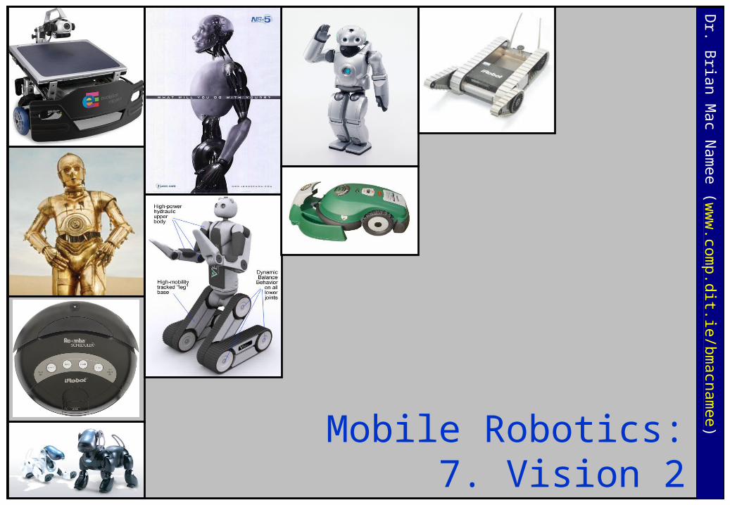
6of22 RGB Colour ModelThink of R, G, B as color orthobasis
(0,1,0) – pure green
(0,0,1) – pure blue
(1,0,0) pure red
(1,1,1) - white
(0,0,0) - black (hidden)

7of25
7of22 HSV Colour Model
More robust against illumination changes
Still must confront noise, specularity etc.

8of25
8of22 Object DetectionSuppose we want to detect an object (e.g., a colored ball) in the field of view
We simply need to identify the pixels of some desired colour in the image…right?
Image coordinates (pixels)
u
v
IO width
height

9of25
9of22 It’s Not That Easy!
Occluded light source
Specularhighlights
Mixedpixels
Complex surfacegeometry (self-shadowing)
Noise!

10of25
10of22 Evolution Robotics’ ViPR System
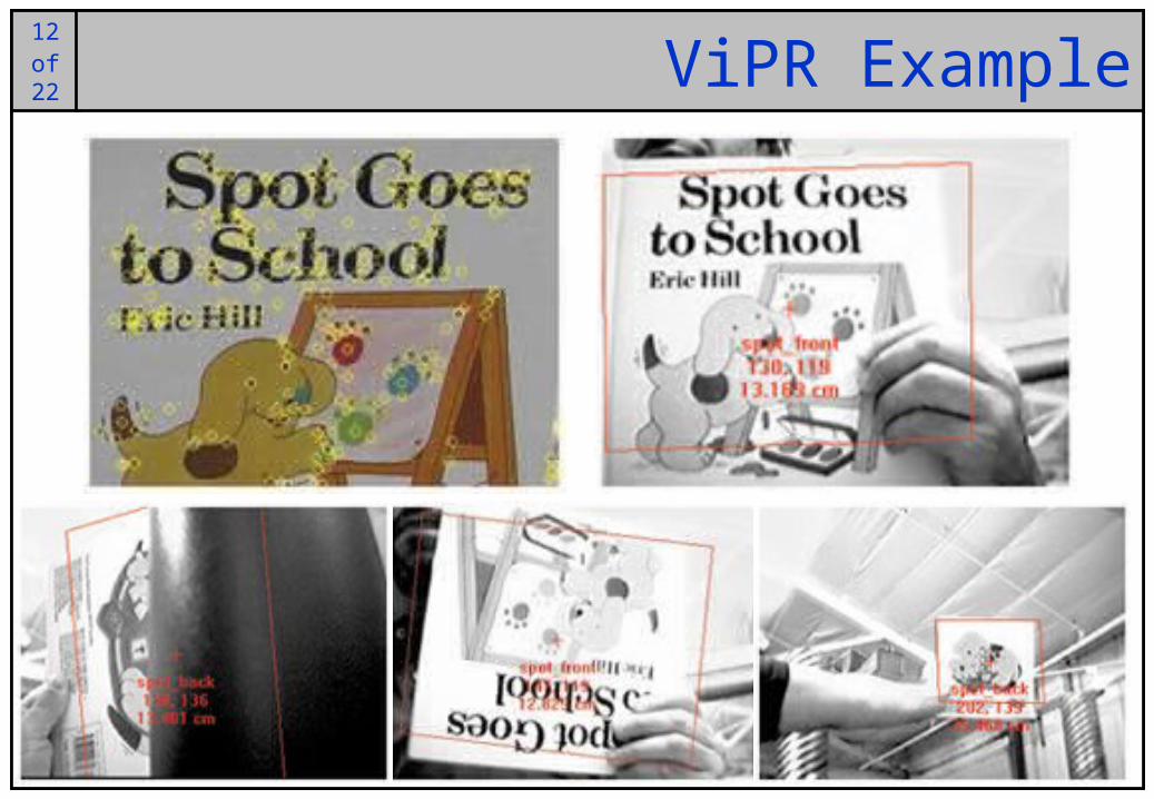
Evolution Robotics ViPR (visual pattern recognition) technology provides a reliable and robust vision solution to object
recognitionThe technique is based on
extracting salient features from an imageSalient features are artefacts such as edges, corners etcThe description of an object is a set of up to a thousand salient features, the textures of the pixels around them and their relationships to each other

11of25
11of22
Evolution Robotics’ ViPR System (cont…)
Object recognition then involves first finding all of the features in a new imageThese features are matched against those of all of the models in a databaseIf many features in a new image are the same as those in a database model, the model is a good candidate matchFurther accuracy is obtained by comparing the relative positions of the matched features in the image and the modelThe model in the database with the best match score is then recognised
12of25
12of22 ViPR Example
13of25
13of22 ViPR Pros & ConsThe advantages of the ViPR system include:
– Invariance to rotation and affine transformation– Invariance to changes in scale– Invariance to lighting changes– Invariance to occlusions– Reliable recognition
However, while the ViPR can be used to recognise symbols and 3D objects it cannot be used to recognise deformable 3D objects such as faces
For more information on the technologies behind ViPR have a look at:“Core Technologies for Service Robotics”, N. Karlsson, M. E. Munich, L. Goncalves,
J. Ostrowski, E. Di Bernardo & P. Pirjanian“Distinctive Image Features from Scale-Invariant Keypoints”, D. Lowe
14of25
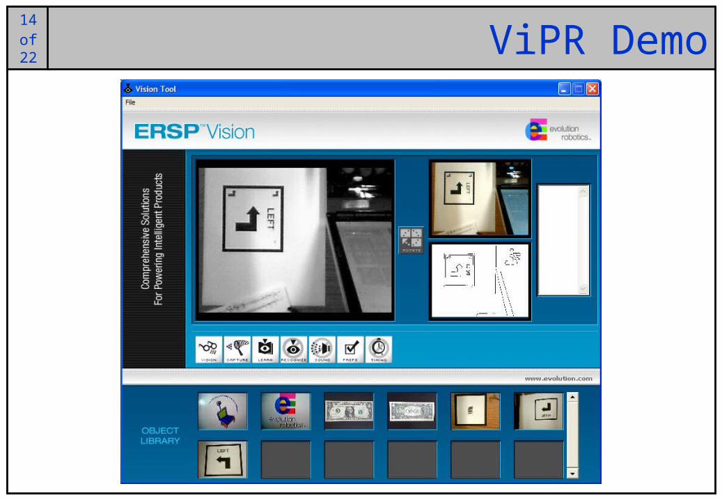
14of22 ViPR Demo

15of25
15of22 Vision Through Colour TrackingOften colour alone can be used to perform vision tasks
We use flood fill techniques like those in Photoshop
Particularly useful in controlled environments

16of25
16of22 Face Tracking Using Colour Alone
Image Acquisition RGB to HSV Conversion Skin Colour Binary Image
Image Closing Segmentation Selection by Size

17of25
17of22 Stereo VisionStereo vision is used to determine distance through differences in images taken from two cameras positioned slightly apart
– Just like our eyes!

18of25
18of22 Stereo VisionIdealized camera geometry for stereo vision

19of25
19of22 Stereo VisionA point visible from both cameras produces a conjugate pair
– Conjugate pairs lie on epipolar line (parallel to the x-axis for the arrangement in the figure above)
From a conjugate pair distance can be estimated
20of25
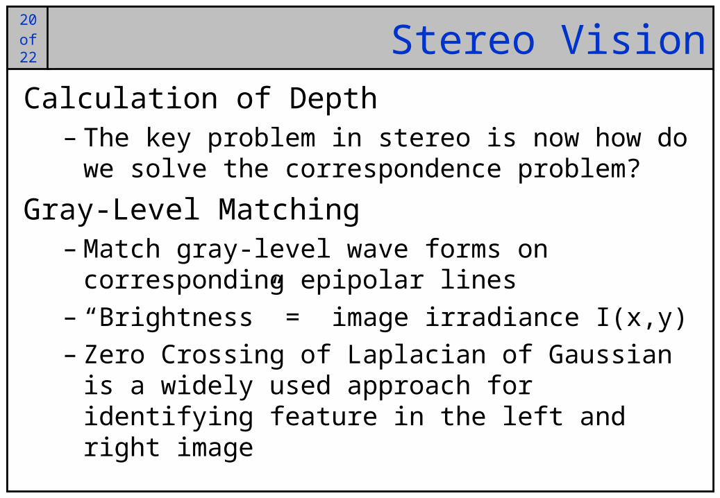
20of22 Stereo VisionCalculation of Depth
– The key problem in stereo is now how do we solve the correspondence problem?
Gray-Level Matching– Match gray-level wave forms on corresponding
epipolar lines– “Brightness” = image irradiance I(x,y)– Zero Crossing of Laplacian of Gaussian is a widely
used approach for identifying feature in the left and right image

21of25
21of22 Stereo Vision Example
Depth image (bright = close, dark = far)
Confidence image (bright =
high confidence)
Vertical edge filtered
left and right images
Original left and right
images

22of25
22of22 SummaryToday we looked at some of the vision techniques commonly used in robotics
We have barely scratched the surface, but hopefully you have gained some appreciation of the difficulties involved

23of25
23of22 Questions?
?
Related Documents