NAMI- 1043 USAARU Serial No. 68-10 INSTRUMENTATION FOR MEASUREMENT OF VESTIBULAR-S IGNIFICANT FORCES IN HE LJCOPTERS W. Carroll Hixson and Jorma 1. Niven 1 0 PRICE s \ CFSTI PRICE(S) $ I Hard copy (HC) Microfiche (M F) . I (THRU) I8 (ACCESSION NUMBER) I d 1 - I U. S. ARMY AEROMEDICAL RESEARCH UNIT NAVAL AEROSPACE MEDICAL INSTITUTE May 1968 This document has been approved for public release and sale; its distribution is unlimited. https://ntrs.nasa.gov/search.jsp?R=19680023261 2018-06-23T01:16:43+00:00Z

Welcome message from author
This document is posted to help you gain knowledge. Please leave a comment to let me know what you think about it! Share it to your friends and learn new things together.
Transcript

NAMI- 1043 USAARU Serial No. 68-10
INSTRUMENTATION FOR MEASUREMENT OF
VESTIBULAR-S IGNIFICANT FORCES IN HE LJCOPTERS
W. Carroll Hixson and Jorma 1. Niven
1 0 PRICE s \
CFSTI PRICE(S) $
I Hard copy (HC)
Microfiche (M F) .
I (THRU) I8 (ACCESSION NUMBER) I
d 1 - I
U. S. ARMY AEROMEDICAL RESEARCH UNIT
NAVAL AEROSPACE MEDICAL INSTITUTE
May 1968
This document has been approved for public release and sale; i t s distribution i s unlimited.
https://ntrs.nasa.gov/search.jsp?R=19680023261 2018-06-23T01:16:43+00:00Z
This document has been approved for pu6lic release and sale; i t s distribution i s unlimited.
INSTRUMENTATION FOR MEASUREMENT OF
VESTIBULAR-S IG N IF ICA NT FORCES IN HELICOPTERS
W. Carroll Hixson and Jorma 1. Niven
Bureau of Medicine and Surgery MF022.03-02-5016.2
U. S. Army Aeromedical Research Unit
NASA Order R-93
Approved by Released by
Ashton Graybiel, M, D. Head, Research Department
Captain J. W. Weaver, MC USN Commanding Officer
21 May 1968
"This research was in part supported by the Office of Advanced Research and Technology, National Aeronautics and Space Administration.
NAVAL AEROSPACE MEDICAL INSTITUTE NAVAL AEROSPACE MEDICAL CENTER
PENSACOLA, FLORIDA 32512

SUMMARY PAGE
THE PROBLEM
The need for airborne instrumentation to measure and record the vestibular- significant flight forces encountered in helicopter operations.
FINDINGS
The deve lopmen t of a se I f-con tained, se I f-powered airborne instrumentation package which can be installed on a noninterference basis in most military helicopters and used for the in-flight acquisition and storage of low-frequency triaxial linear acceleration and triaxial angular velocity data.
I
ACKNOWLEDGEMENT
The authors wish to acknowledge Mr. C. A. Lowery of the Medical Electronics Branch for the construction of the instrument package and the collection of field data.
The findings in this report are not to be construed as an official Department of the Army position, unless so designated by other authorized documents.
Trade names of materials or products of commercial or nongovernment organizations are cited only where essential to precision in describing research procedures or evalu- ation of results. Their use does not constitute official endorsement or approval of the use of such commercial hardward or software.
.. i l
1 NTRODUCTI ON
One of the many approaches personnel of this laboratory choose to use in their investigation of pilot disorientation i s the identification of specific flight environmental factors in operational flying which can affect the visual and/or vestibular sensing capability of the pilot. As part of this program, attention has been given to the in- flight acquisition of aircraft acceleration data in order to place some quantitative weight on the potential contribution of this element of the flight environment to vestibular disorientation. This report presents a brief technical description of a relatively low-cost airborne instrumentation system which was developed to measure and record triaxial linear and angular motion data in conventipnal military helicopters performing rated tactical maneuvers as we1 I as routine flight operations.
DESIGN FACTORS
The study goal of collecting triaxial motion data in a wide variety of military helicopters that would necessarily be assigned to many different organizational comm'ands was in itself a significant design factor. It i s a fact of l i fe that, when per- forming research in the operational situation, a reasonable amount of data in a reason- able amount of time can be collected only when the related instrumentation can be installed on an almost complete noninterference basis with respect to both the aircraft proper and i t s flight crew. Any installation which requires a modification of the air- craft structure, involves a relocation of any interior or exterior equipment, demands an aircraft electrical power source, alters any operational tasks of the crew, or requires complicated in-flight calibration or adjustment procedures wi l I result in delay of the project and decrease the amount of flight time available for experimentation. For these reasons, it was considered essential that the instrumentation system be self-contained and self-powered, and that it place minimal operating demands on the flight crew.
The proposed objective also brought about the decision to place init ial emphasis on the measurement of the motions of the aircraft proper rather than of one of its crew members so that a comparative evaluation could be made of the flight motions associated with different types of helicopters. In effect, it was decided to hard-mount the transducer assembly to the aircraft structure at, or immediately adjacent to, the crew station of interest. The alternative approach of fixing a subminiature transducer package on the helmet, or directly to the head, of a crew member was not considered at this point in the project because of the extreme differences which exist between the characteristics of the acceleration patterns produced by aircraft motions and those produced by normal head movements. The measurement significance of these often overlooked differences can be illustrated as follows. Consider some turn maneuver of an aircraft which produces a relatively constant angular acceleration leve I of approxi- mately 10 deg/sec2 for several seconds or more, i.e., a recognizable vestibular stimulus. If one fixed an angular accelerometer to the aircraft structure, selecting a transducer with low natural frequency and high damping ratio characteristics, this stimulus could be readily detected even with an accelerometer having a full-scale range on order or so greater than 10 deg/sec2.
1

Now consider the alternative approach of measuring this stimulus with a head- mounted accelerometer with the objective of gaining a complete and faithful profile of inertial head accelerations in their entirety. An immediate consequence of this approach i s that during the maneuver, the involuntary head movements of the pilot that wi l l occur, and the voluntary movements that may occur, w i l l produce head accelerations with peak levels far exceeding those produced by the aircraft maneuver. As measured in this laboratory, a quick rotation of the head about the z axis can result in peak angular acceleration levels of 5000 deg/sec2 or more. Even i f the pilot were seated in a motionless environment, he would find i t difficult to maintain the cyclic angular oscillations of his head below the 50-to 100-deg/sec2 range. This quiescent level would obviously be of much greater magnitude in a vibrating helicopter. As a result of the finite dynamic range limitations of a l l accelerometers, i t would be extremely difficult to recover accurately the desired information regarding aircraft angular acceleration from the much higher level angular accelerations produced by movement of the head. The same masking effect occurs, but on a more limited basis, when head-mounted angular velocity transducers are used to quantify the over-all angular motion stimulus. A quick rotation of the head can produce a peak angular velocity of over 600 deg/sec (100 rpm) .
The relatively high level of the linear and angular vibrations of helicopters, coupled with the decision to collect the init ial flight data with a transducer assembly fixed to the aircraft structure, led to the selection of angular velocity as the instrument- ed parameter of the aircraft's angular flight motions, If an angular accelerometer with a frequency response sufficiently great to define properly the amplitude-time profile of the helicopter angular accelerations i s structure mounted, there i s a high probability of transducer overload due to cyclic angular vibration e If an accelerometer with a full-scale sensitivity large enough to prevent overload is chosen, then a poor signal- to-noise ratio results because the level of the angular accelerations due to a given flight profile are far less than those due to the cyclic oscillations of the structure. This potential for accelerometer overload occurs even during straight and level flight. was decided, therefore, to use angular velocity transducers to describe the angular element of the flight force environment because their inherent integration property i s advantageous in the presence of high-frequency angular vibration. Since such trans- ducers directly establish the presence of a constant velocity state during a given flight maneuver or operation they are of obvious value also in detecting the potential for angular Coriolis stimulation. Since research interest in the vestibular area i s centered primarily on low-frequency stimuli, transform of the velocity data to an acceleration form i s easily carried out in the laboratory by digital measurement of slope. For similar reasons, angular velocity transducers w i l l be selected for installation on the pilot's helmet when the measurement program is extended to the definition of head movements.
A summary of several other pertinent design factors includirig frequency response, recording time, and system accuracy follows. In the vestibular area, it is rare that stimuli with a spectrum beyond 0-1 cps or, at most 0-5 cps, are used to investigate the response capabilities of the labyrinth sensors. However, because of the relatively great range of the low-fr-equency vibrations present in helicopters and their potential
2

for vestibular stimulation, it was decided to extend the frequency response of the linear and angular measurement channels to approximately 20 cps. If analyses of the flight data indicate that a frequency spectrum of lesser extent is of primary value, then additional filtering can be introduced during the laboratory data-reduction phase. If a frequency spectrum of greater extent becomes of interest, the previously described Triaxial Accelerometer Module (2) will provide the capability of extending the linear acceleration measurements of vibration to beyond 100 cps. A minimum continuous recording time of 90 min was selected for the self-powered system. With this amount of time, data could be collected with the objective of deriving an amplitude distri- bution of the flight forces encountered throughout typical missions as well as measuring the profile associated with specific flight maneuvers. Since the data are to serve a measurement function rather than an aircraft control or guidance one, and since data
. would be collected in a wide variety of aircraft flown by different pilots under widely varying weather conditions, an overall system accuracy of less than *5% was considered an adequate objective which would be compatible with the assigned budget.
0
I NS TR U ME NTAT I 0 N D ETA I LS
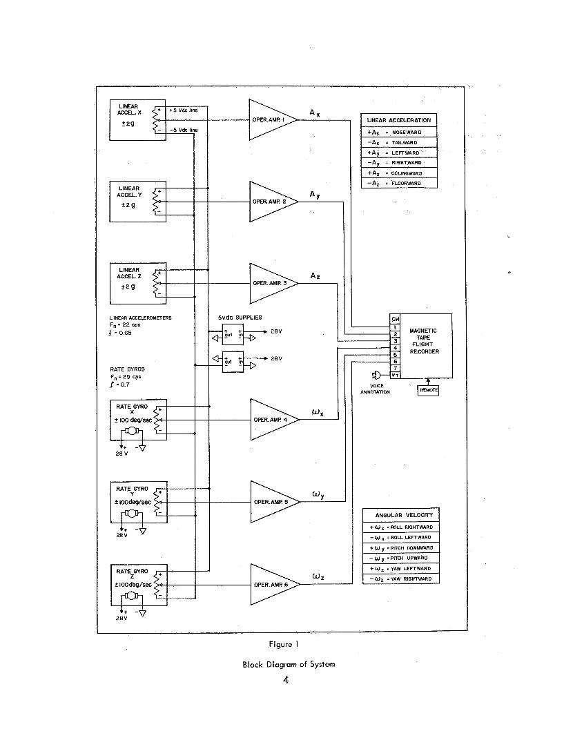
A block diagram of the instrumentation developed to meet these various criteria i s shown in Figure 1 . The basic elements of the system are three orthogonally mounted linear accelerometers which measure the instantaneous resultant linear acceleratian of the aircraft; three similarly oriented rate gyros which measure the resultant angular velocity; six amplifiers which serve a signal-conditioning function; and a magnetic tape instrumentation recorder which stores the in-flight motion data. The three linear channels, identified as A,, A and A, , record the instantaneous linear acceleration !, of the aircraft along its roll, pitch, and yaw axes, respectively. The three angular channels, identified as O, , a,, and a,, record the instantaneous angular velocity of the aircraft about its roll, pitch, and yaw axes, respectively.
The A, , A , , and A, transducers are hermetically sealed, gas-damped, potentiometer readout, linear accelerometers (Humphrey Inc. Model lA45) which are approximately 9 in. by 1 in. by 1 in. and weigh about 1 oz. Pertinent manufacturer's specifications include a full-scale range of *2g ; a natural frequency of 22 cps; a damping which remains between 0.6 and 0.7 over the -40° to +165O F temperature range; a 5000-ohm output potentiometer with a 150-turn equivalent resolution and a power dissipation of 0.5 W based on a maximum wiper current of 10 mA; a static threshold of less than 0.8 % of ful l scale; and a full-scale accuracy of 2 %. For applications involving high-performance aircraft, a f 5 g accelerometer is available for substitution in the A, channel.
The angular transducers are dc-operated gimballess rate gyros (Humphrey Inc. Series RG-28) which provide a potentiometer readout of the instantaneous angular velocity input. Each gyro has a diameter of 1.75 in., a length of 3.72 in., and a weight of approximately 14 oz. Basic specifications include a full-scale range of f 100 deg/sec; a natural frequency of 25 cps; a damping ratio of 0.7 kO.2; a 5000-ohm output potentiometer with characteristics similar to those of the linear accelerometers;
3
I 1
+5 Vdc line LINEAR
2 29
CCELERDMETERS
5 = 0.65
RATE GYROS F, = 25 cps 1 ~ 0 . 7
5vdc SUPPLIES
ANNOTATION $ OF€R.AMI? 4
ANGULAR VELOCITY
++ -0 2 8 V
Figure 1
Block Diagram of System
4
an accuracy envelope o f f 1 % at zero output increasing to f 2 % at full-scale velocity; and a repeatability and hysteresi Each gyro spin-motor requires 28 10 % for operation and draws a maximum running current of 300 mA, The peak s urrent i s defined by a 2.5-A current pulse of 50-ms duratiQn with approximately 15 sec required to reach running speed. A triaxial mounting frame provides orthogonal
As indicated in Figure 1, the are wired in parallel and connected o miniature dc-to-dc power supplies (Bourns Inc. Model 3960) which furnish zk5 Vdc relative to circuit ground. Each of these input-output isolated supplies i s rated to deliver 5 Vdc at currents up to 100 mA with a line regulation of 0.005 Vdc over the 24-32 V input range and a temperature sensitivity of kO.01 % per deg C with constant input. The wiper arm of each output potentiometer, producing an output voltage of rt5 V for full-rated motion input, i s then connected to the input of a dc operational amplifier (Philbrick Research Model P25C) which permits the transducer to drive the rated 20,000 ohm input impedance of the related tape-recorder channel with minimal loading effects. Resistive and capacitive feedback around each amplifier allows operator control of circuit gain and the high- frequency rolloff point with the actual circuitry following that used for the Triaxial Accelerometer Module (2).
% of full-scale within the above envelope.
tion of the gyros.
nds of the six transducer output potentiometers
'
"
A photograph of the gyro mounting frame with the three rate gyros installed i s shown in Figure 2. The frame also serves as an orthogonal mount for the three linear accelerometers and as a fastening base for the two 5-Vdc potentiometer supplies. A l l input and output circuitry to the finished assembly i s routed through a single connector installed at the rear of the unit. The complete six-channel transducer assembly is compact and weighs only 4 Ibs, 10 oz.
A photograph of the magnetic tape recorder selected for in-flight storage of the measurement data i s shown in Figure 3. The recorder i s a small battery-powered, 7-channel, magnetic tape unit (Lockheed Electronics Co. Model 4170) which utilizes FM record/reproduce techniques on &-in. tape and is fully lRlG compatible. The recorder has a differential capstan-drive system with phase-lock servo motor control of speed and a special oscillator to provide 0.1 % servo drift over the 32 to 120 deg F temperature range. Plug-in electronics and internal motor speed adjustments allow record/reproduce speeds of 15, 3 2, and 7 Q ips, with the condition that the instrument can only record or only reproduce depending on the type of amplifiers installed. How- ever, an eighth electronic channel and a switchable reproducer head assembly permit the output level of each channel to be monitored sequentiaIly.while recording; The pertinent laboratory-based specifications at the 7 -ips speed selected to record the flight motions include an rms signal-to-noise ratio of 40 db, and a maximum peak-to- peak flutter of 0.5 % over a spectrum of 0-150 cps. The operation of the recorder for the desired 90 min at this speed is compatible with both the power capability of the internal battery and a 3, 150-ft supply of 0.65-mil thick tape on the 7-in. reels. Ancillary features include an edge track for voice annotation and a remote control box
5
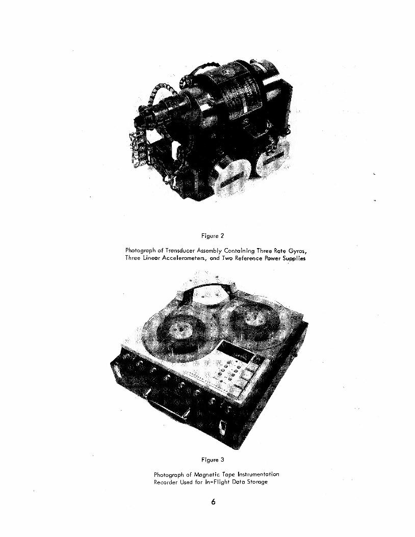
Figure 2
Photograph of Transducer Assembly Containing Three Rate Gyros, Three Linear Accelerometers, and Two Reference Power Supplies
Figure 3
Photograph of Magnetic Tape Instrumentation Recorder Used for In-Flight Data Storage
6

for pilot operation of the system. The entire recorder, including a l l electronics and the battery power source i s housed in a single case which has an approximate width of 14 in., a depth of 15&in., a height of 62in., and a weight of less than 30 Ib. The recorder features of best advantage to this application were i t s self-contained packaging and i t s low power requirement of less than 12 W based on 750 mA at 17 Vdc.
A photograph of one particular configuration of the over-all system i s shown in Figure 4. The transducer assembly, signal-conditioning circuitry, and nickel-cadmium batteries are installed in a case identical to that used for the tape recorder which, in this photograph, i s the uppermost module. A minimal amount of vibration isolation i s
Figure 4
Photograph of One Particular Configuration of System. Transducer Assembly, Signal-Conditioning Amplifiers, and Batteries are Housed in
Bottom Case Which i s Identical to the Tape Recorder Case Installed at the Top.
provided for the tape recorder by means of two % -in. foam neoprene pads placed above and immediately beneath the recorder case. The remote control box, technician's microphone, and related cables can be seen at the right. Other configurations can be achieved readily by separating the transducer assembly from the remaining components.
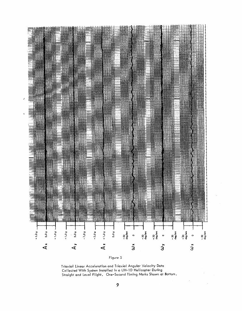
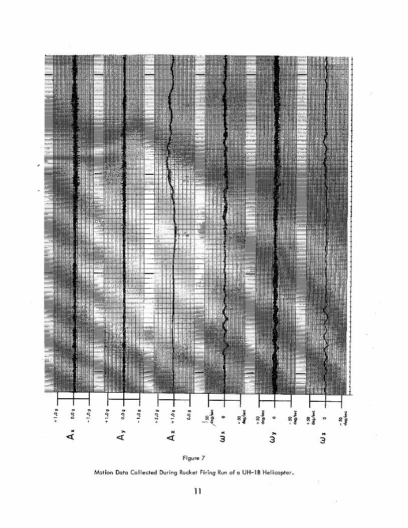
A few sample records illustrating typical flight data collected with the instrumen- tation system, configured as shown in Figure 4 and installed in various helicopters, are presented in Figures 5 through 7. For each of these records, the system was installed immediately adjacent to the pilot station and oriented so that i t s x , y , and z axes of
7

sensitivity were in alignment with the roll, pitch, and yaw axes of the aircraft with +x directed forward. The stored flight data were played back in the laboratory and dis- played on a conventional direct-writing recorder with a frequency response of 0 to 100 cps. Accordingly, the upper frequency limit of the measurements as shown in these records i s determined by the transducer. In a l l cases, an upward-directed displacement from the given reference corresponds to a positive output voltage such that + A, , + A, , and + A, describe noseward, leftward, and ceilingward linear accelerations of the heli- copter while + w,,I-o,, and+&, correspond to roll rightward, pitch downward, and yaw leftward angular velocities. One-second timing marks are shown at the bottom of each record.
A subsequent report w i l l detail the helicopter flight measurement data currently x
being collected with the system.
REFERENCES
1. Hixson, W. C., Niven, J. I., and Correia, M. J., Kinematics nomenclature for physiological accelerations: With special reference to vestibular appli- cations. Monograph 14. Pensacola, Fla .: Naval Aerospace Medical Institute, 1966.
2. Hixson, W. C., A triaxial accelerometer module for vestibular application. NAMI-1040. USAARU Serial No. 68-9. Pensacola, Fla.: Naval Aerospace Medical Institute, and U. S. Army Aeromedical Research Unit, 1968.
8
m m m m m m m m m 0 0 " 0 0 0
9 9 9 3 2 2 a 3 0 0% 8% 0 0 % a% 0 a$ + I + I + + + d IU * a tu + d 9 9 9
- a - 0 - - 0 - 8 - 0 + v
d Tr N
a a x
3 * 3
Figure 5
Triaxial Lineor Accelerotion and Triaxial Angular Velocity Data Collected With System Installed in a UH-1D Helicopter During Straight and Level Flight. One-Second Timing Marks Shown a t Bottom.
N
3
9

m m m m m m m m m
I + I - 0 - - 0 % -
0 0 0 0 " + 9 9 9 : E x & 0 & a% 0 ,s & 0 8$ 9 9 9
7-8 + t I V + + +t I t + t x h N
a a a Y
3 299
3
Figure 6
Motion Doto Collected During on Auto-rotation of a UH-1D Helicopter
N
3
10
s-l
a M x
3 * 3
Figure 7
M3tion Data Collected During Rocket Firing Run of a UH-1B Helicopter.
N
3
1 1
O R , G I N A T I N O A C T I V I T Y (Corporate author)
Naval Aerospace Medical Institute Pensacola, Florida 32512
Ze. R E P O R T S E C U R I T Y C L A S S I F I C A T I O N
Unclassified 2b. G R O U P
N/A
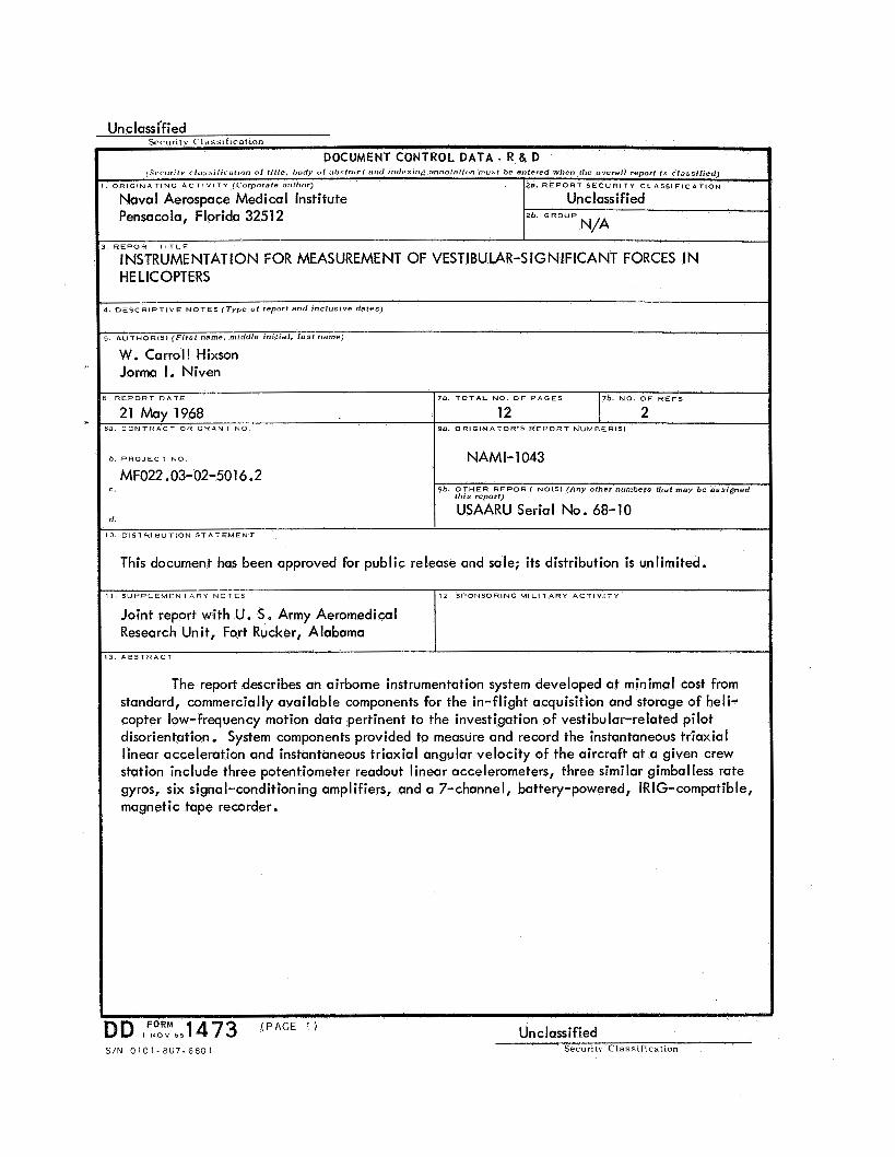
The report describes an airborne instrumentation system developed at minimal cost from standard, commercially available components for the in-flight acquisition and storage of heli- copter low-frequency motion data pertinent to the investigation of vestibular-related pilot disorientation. System components provided to measure and record the instantaneous triaxial linear acceleration and instantaneous triaxial angular velocity of the aircraft at a given crew station include three potentiometer readout linear accelerometers, three similar gimballess rate gyros, six signal-conditioning amplifiers, and a 7-channe1, battery-powered, IRIG-compatible, magnetic tape recorder.
R E P O R T D A T E
21 May 196% a C O N T H A C T O R G R A N T NO
b . P R O J E C T N O
MF022.03-02-5016.2 C .
d .
I D IFNo61/M651 473 ( P A G E Unclassified
7 6 . N O O F R E F S 78. T O T A L NO O F P A G E S
12 2 9a. O R I G I N A T O R * S R E P O R T N U M B E R I S )
NAMI- 1043
9 6 . O T H E R R E P O R T N O ( S 1 (Any other numbers that m a y be a s s i g n e d th is repor?)
USAARU Serial No. 6%- 10
Securtt\ Class i f ica t ion S/N 0 1 0 1 - 8 0 7 - G 8 0 1
I S U P P L E M E N T A R Y N O T E S
Joint report with U. S. Army Aeromedical Research Unit, Fort Rucker, Alabama
12 S P O N S O R I N G M I L I T A R Y A C T I V I T Y

Unclassified Security Classification
I L I N K E Y W O R D S
R O L E
lnstrumentat ion
He1 icopten
Linear acce lera t ion
Angular velocity
Vestibular system
Pi lot disorientation
W T - -~
L I N K 8
POLE -
111
R O L E - W T -
FORM ( BACK ) Unclassified 1 N O V O S
Security Classification (PAGE 2)
Related Documents