1 Moving to Use Cases Chapter 2 – Use Cases Text plus Personal Notes

1 Moving to Use Cases Chapter 2 – Use Cases Text plus Personal Notes.
Dec 19, 2015
Welcome message from author
This document is posted to help you gain knowledge. Please leave a comment to let me know what you think about it! Share it to your friends and learn new things together.
Transcript

1
Moving to Use Cases
Chapter 2 – Use Cases Text plus
Personal Notes
2
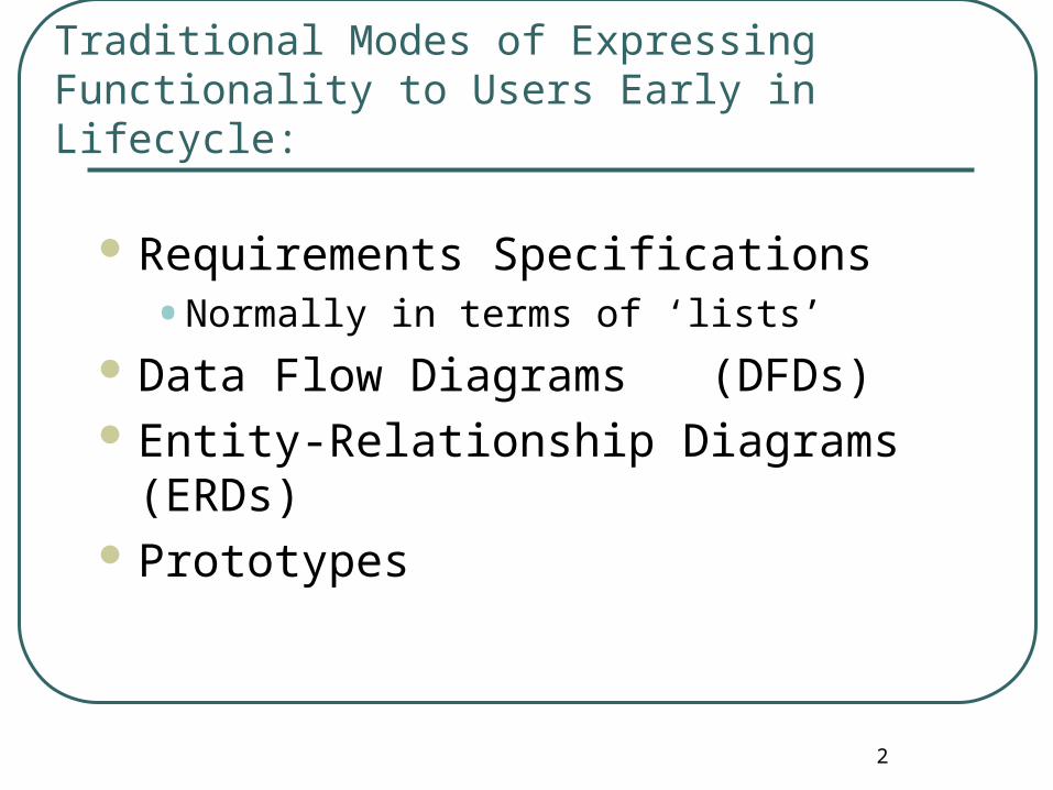
Traditional Modes of Expressing Functionality to Users Early in Lifecycle:
Requirements Specifications• Normally in terms of ‘lists’
Data Flow Diagrams (DFDs) Entity-Relationship Diagrams (ERDs) Prototypes
3
Discussing these technologies
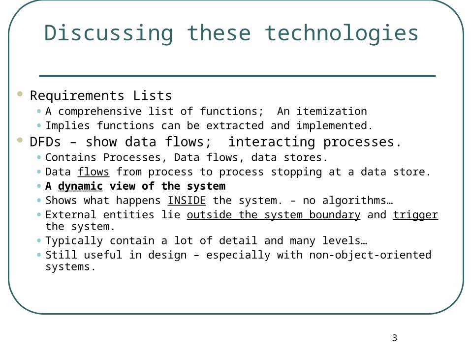
Requirements Lists• A comprehensive list of functions; An itemization
• Implies functions can be extracted and implemented. DFDs – show data flows; interacting processes.
• Contains Processes, Data flows, data stores.
• Data flows from process to process stopping at a data store.
• A dynamic view of the system
• Shows what happens INSIDE the system. – no algorithms…
• External entities lie outside the system boundary and trigger the system.
• Typically contain a lot of detail and many levels…
• Still useful in design – especially with non-object-oriented systems.
4
1
Data Flow Diagram ConventionsData Flow Diagram Conventions
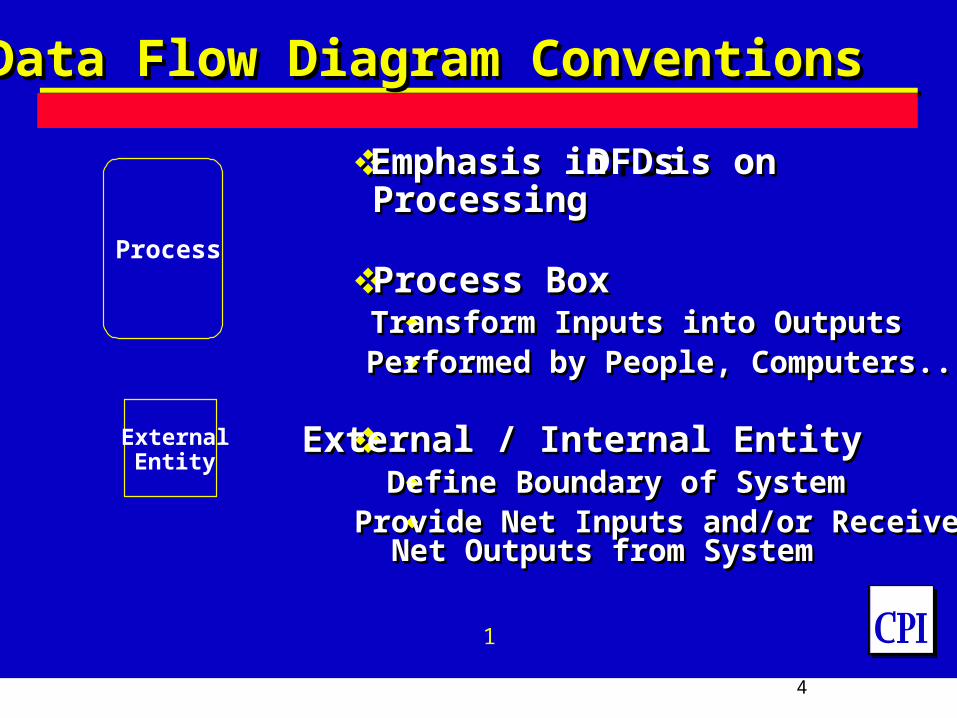
Emphasis inDFDsis on Processing
Process BoxTransform Inputs into OutputsPerformed by People, Computers...
External / Internal EntityDefine Boundary of SystemProvide Net Inputs and/or Receive Net Outputs from System
Emphasis inDFDs is on Processing
Process BoxTransform Inputs into OutputsPerformed by People, Computers...
External / Internal EntityDefine Boundary of SystemProvide Net Inputs and/or Receive Net Outputs from System
Process
ExternalEntity

57
Data Flow Diagram ConventionsData Flow Diagram Conventions
Data Stores -Open-EndedCabinets, Logs, Files.Data “at rest”
Data FlowsDepict Data Flowing Into or Out of a
ProcessFlowlinestypically labeledDirectionalTypically Represent Reports, Forms,
Documents, Memos, Phone Calls, Retrievals, Letters, ...
Data Stores -Open-EndedCabinets, Logs, Files.Data “at rest”
Data FlowsDepict Data Flowing Into or Out of a
ProcessFlowlinestypically labeledDirectionalTypically Represent Reports, Forms,
Documents, Memos, Phone Calls, Retrievals, Letters, ...
68
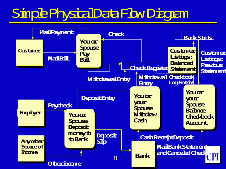
Mail Bill
Mail Payment
Customer
Withdrawal Entry
Check
CustomerListings:BalancedStatement
CustomerListings:BalancedStatement
BankStmts
CustomerListings:PreviousStatements
WithdrawalEntry
You or your SpouseBalanceCheckbookAccount
You or your SpouseWithdrawCash
Check Register
Mail Bank Statementand Canceled ChecksBank
You or SpouseDeposit money in to BankAny other
Source ofIncome
Employer
You or SpousePayBill
Paycheck
Other income
Deposit Entry
DepositSlip
Cash Receipt Deposit
CheckbookLog Entries
Simple Physical Data Flow Diagram
712
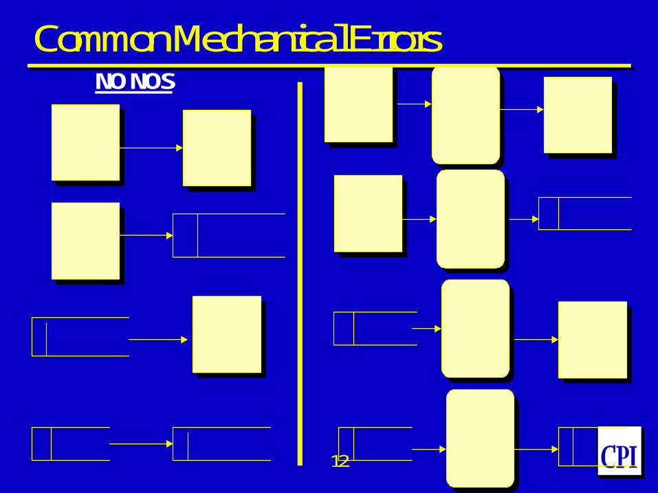
NO NOS
Common Mechanical Errors
814
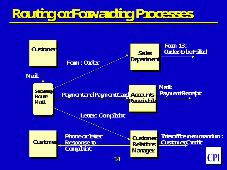
Routing or Forwarding ProcessesRouting or Forwarding Processes
Secretary:RouteMail
Customer
Form 13:Order to be Filled
Mail:Payment Receipt
Interoffice memorandum:Customer Credit
Form: Order
Payment and Payment Card
Letter: Complaint
Phone or letterResponse to Complaint
CustomerSales
Department
AccountsReceivable
CustomerRelationsManager
915
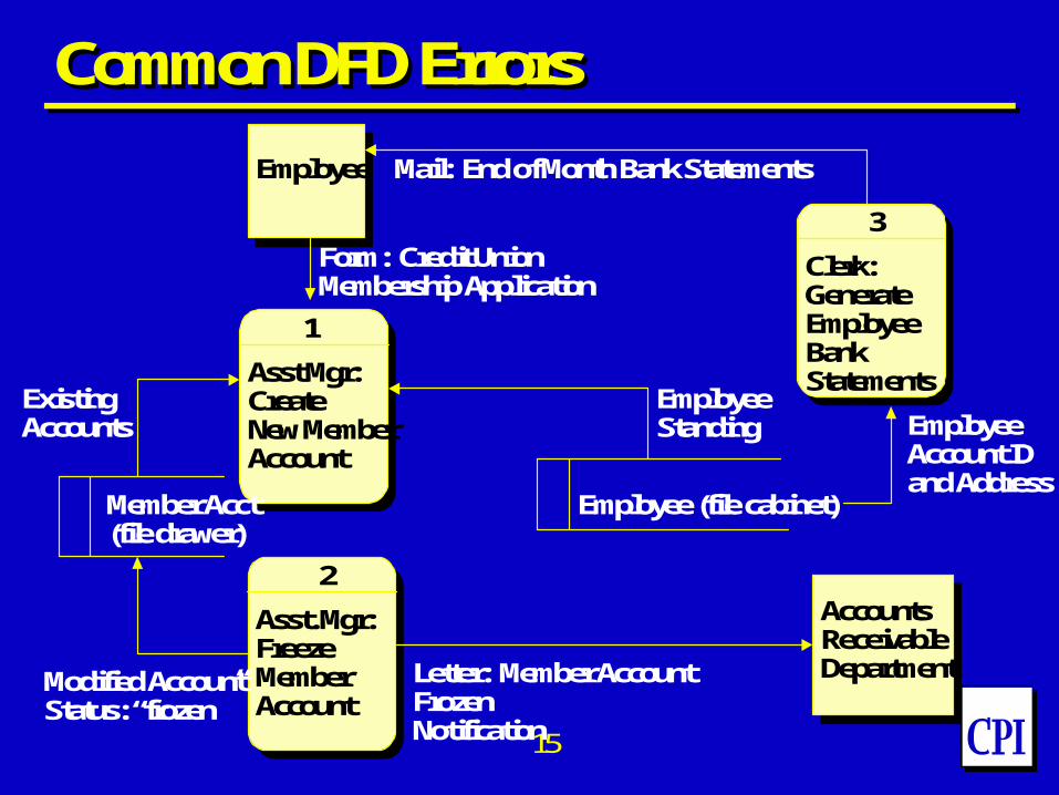
Common DFD ErrorsCommon DFD Errors
Employee
Asst Mgr:CreateNew MemberAccount
Asst. Mgr:Freeze MemberAccount
Clerk:GenerateEmployeeBankStatements
AccountsReceivableDepartment
Member Acct(file drawer)
Employee (file cabinet)
Mail: End of Month Bank Statements
Form: Credit Union Membership Application
ExistingAccounts
Modified AccountStatus: “frozen”
Letter: Member Account FrozenNotification
EmployeeAccount IDand Address
EmployeeStanding
1
2
3
1019
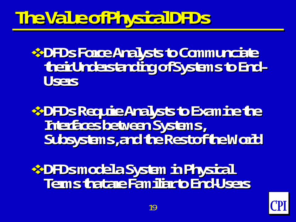
The Value of PhysicalDFDsThe Value of PhysicalDFDs
DFDsForce Analysts toCommunciatetheir Understanding of Systems to End-Users
DFDsRequire Analysts to Examine the Interfaces between Systems, Subsystems, and the Rest of the World
DFDsmodel a System in Physical Terms that are Familiar to End-Users
DFDsForce Analysts toCommunciatetheir Understanding of Systems to End-Users
DFDsRequire Analysts to Examine the Interfaces between Systems, Subsystems, and the Rest of the World
DFDsmodel a System in Physical Terms that are Familiar to End-Users
1111
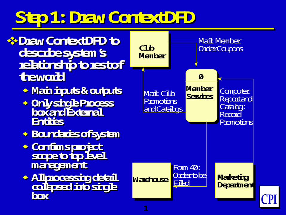
Step 1: Draw Context DFDStep 1: Draw Context DFD
Draw Context DFD to describe system’s relationship to rest of the worldMain inputs & outputsOnly single Process
box and External Entities
Boundaries of systemConfirms project
scope to top level management
All processing detail collapsed into single box
Draw Context DFD to describe system’s relationship to rest of the worldMain inputs & outputsOnly single Process
box and External Entities
Boundaries of systemConfirms project
scope to top level management
All processing detail collapsed into single box
MemberServices
ClubMember
Warehouse MarketingDepartment
Mail: MemberOrder Coupons
Mail: ClubPromotionsand Catalogs
ComputerReport andCatalog: RecordPromotions
Form 40:Order to beFilled
0
1233
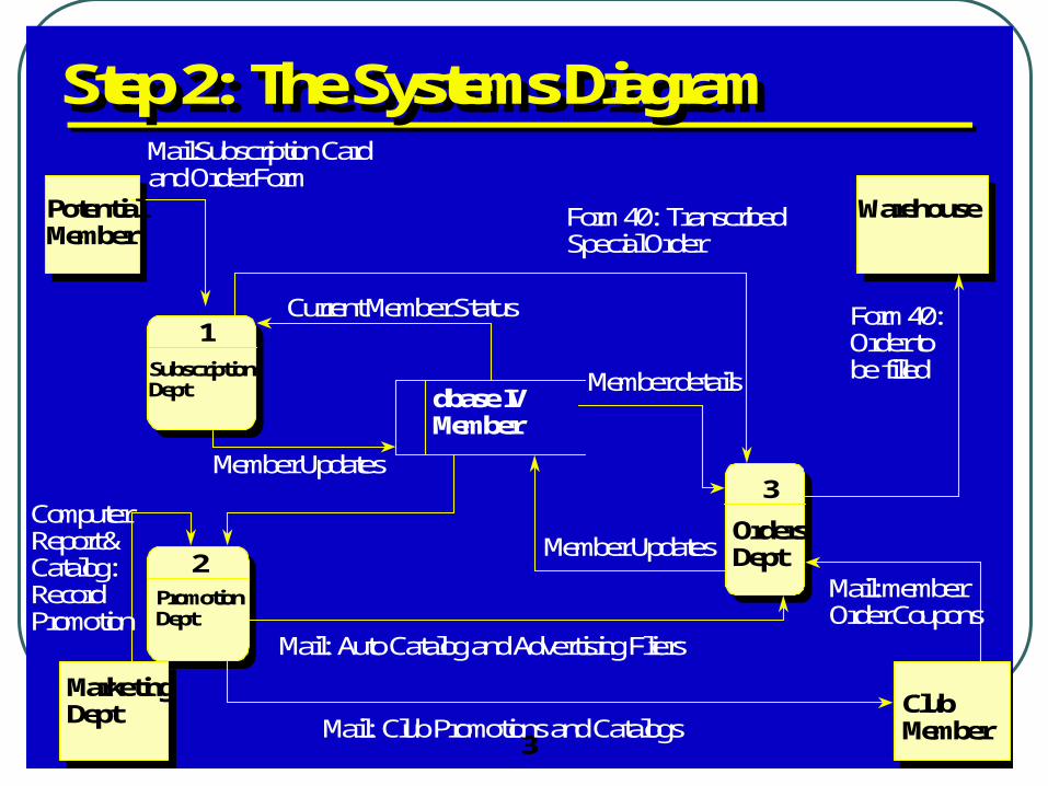
Step 2: The Systems DiagramStep 2: The Systems Diagram
PotentialMember
MarketingDept Club
Member
Warehouse
SubscriptionDept
PromotionDept
OrdersDept
dbase IVMember
Mail:Subscription Cardand Order Form
Current Member Status
Form 40: TranscribedSpecial Order
Member Updates
ComputerReport &Catalog:RecordPromotion
Mail: Club Promotions and Catalogs
Mail: Auto Catalog and Advertising Fliers
Mail: memberOrder Coupons
Form 40:Order tobe filledMember details
Member Updates
1
2
3

13
Step 3 – Middle Level – Identification of Transaction Flow
44
-
PotentialMember
ClubMember
ProcessSubscriptionTransaction
ProcessMembership
RenewalTransaction
ProcessMembershipCancellationTransaction
A/RDepartment
dbase IV Member
Form letter: MembershipWelcome or Denial
Mail SubscriptionCard & Order Form
Form 40: Transcribed Special Order
Current Member Status
FormLtr: Notice of Pending Bonus
Mail: MbrshpRenewal Slip
Mail: Renewal WelcomeLtr
FormLtr: MembershipCancellation Confirmation
Mail/Phone: MembershipCancellation (letter)
MemberUpdates
Form 25: OutstandingCredit Notice
Member Updates
1.1
1.2
1.3

14
ApplicationNotebook
Past MemberFile Cabinet
dbase IVMember
Form letter: Membership welcome or denial
Mail: Subscription card and order form
Subscription card and order via advertisement
ProcessedApplication
ProcessedApplication
Standing at timeacoount was closed
Special Order Form
Form 40: TranscribedSpecial Order
Existing Member’s bonus order (bottom)
Form ltr:Notice of PendingBonus Prospective Member application and order
New memberdetails
Currentmemberstatus
Screen:CurrentMemberStatus
Subscriptioncard and ordervia referral
PotentialMember
ClubMember
Clerk:TranscribeOrder
1.1.3
A
1.1.5Clerk: Notify Applicant of Status
Mail Clerk:DistributeMail
1.1.1
1.1.6dbase IVprogram:Chk RefrlValidity
1.1.7dbase IV programAdd newmember
1.1.2Subscript
ionclerk:
ApproveApplicant
1.1.4
Clerk:Notify Applicantof Status
G
A
AF
A
F
D
DC
A
E
A
B
Step 4 – Detailed Transaction Description
15
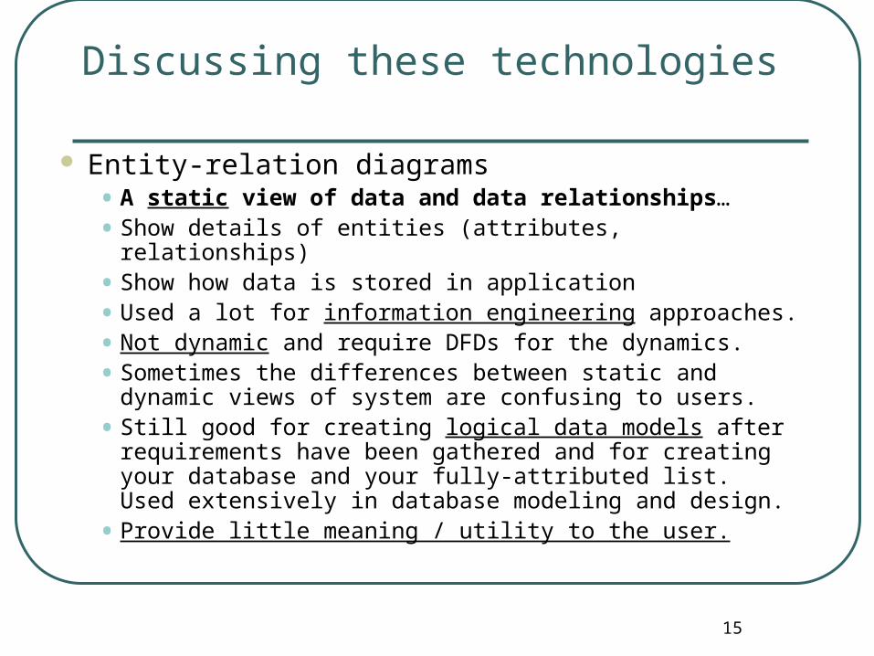
Discussing these technologies
Entity-relation diagrams• A static view of data and data relationships…
• Show details of entities (attributes, relationships)
• Show how data is stored in application
• Used a lot for information engineering approaches.
• Not dynamic and require DFDs for the dynamics.
• Sometimes the differences between static and dynamic views of system are confusing to users.
• Still good for creating logical data models after requirements have been gathered and for creating your database and your fully-attributed list. Used extensively in database modeling and design.
• Provide little meaning / utility to the user.

168
CSX
Data Modeling with Entity Relationship DiagramsData Modeling with Entity Relationship Diagrams
ERDs define relations between data objects Considered the cornerstone in Data Modeling Shows attributes/properties for each data object
Producer/consumer of information
Shows relationships connecting objects Number of objects in the relationship (cardinality)
{1-1; 1-n; m-n} Indicates if relationship is required or not (modality)
{0 or 1}
179
CSX
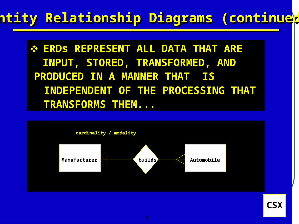
Entity Relationship Diagrams (continued)Entity Relationship Diagrams (continued)
ERDs REPRESENT ALL DATA THAT ARE INPUT, STORED, TRANSFORMED, AND
PRODUCED IN A MANNER THAT IS INDEPENDENT OF THE PROCESSING THAT TRANSFORMS THEM...
Manufacturer builds Automobile
cardinality / modality

1810
CSX
Entity Relationship Diagrams (continued)Entity Relationship Diagrams (continued)
Oftentimes specific attribute values may be shown in tables
|<------------------- ATTRIBUTES (FIELDS / MEMBERS) ---------------- >
MAKE MODEL ID# BODY TYPE COLOR REFERENC E
FORD MUSTANG 1234 2-DOOR RED RFR
PLYM VOYAGER 2345 4-DOOR WHITE CAR
HONDA LX 4455 4-DOOR GREEN JDR
PONT GRAN AM 8899 2-DOOR RED ETS
|<------------------- ATTRIBUTES (FIELDS / MEMBERS) ---------------- >
MAKE MODEL ID# BODY TYPE COLOR REFERENCE E
FORD MUSTANG 1234 2-DOOR RED RFR
PLYM VOYAGER 2345 4-DOOR WHITE CAR
HONDA LX 4455 4-DOOR GREEN JDR
PONT GRAN AM 8899 2-DOOR RED ETS
19
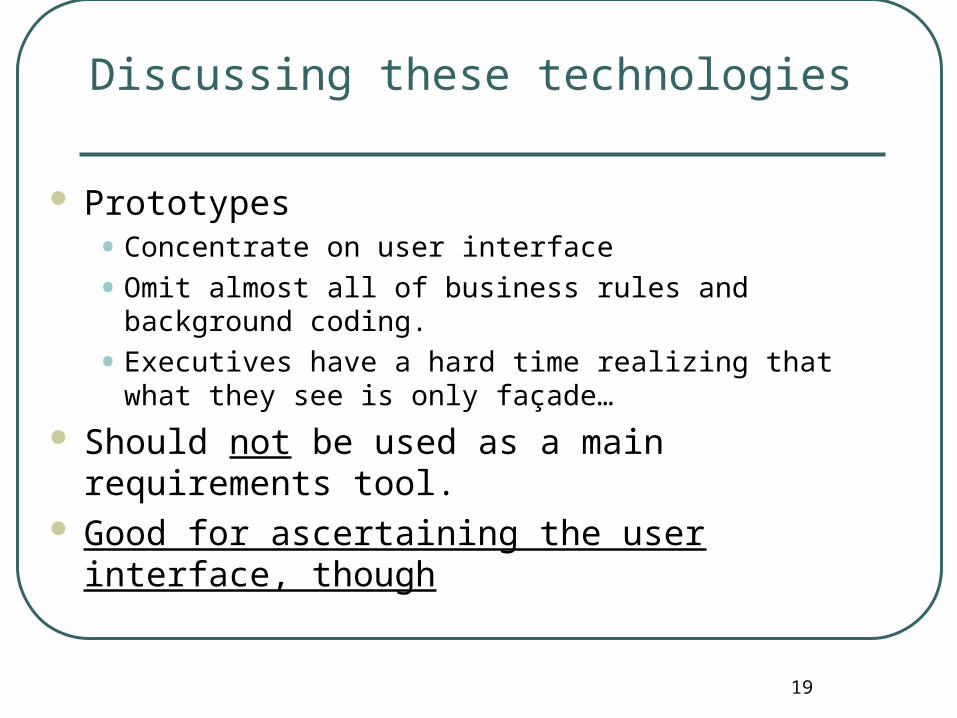
Discussing these technologies
Prototypes• Concentrate on user interface
• Omit almost all of business rules and background coding.
• Executives have a hard time realizing that what they see is only façade…
Should not be used as a main requirements tool. Good for ascertaining the user interface, though

20
Discussion: Summary of these Technologies
Requirements Specs are rarely used once application is produced. (Discuss…)
DFDs and ERDs are useful for moving into programming and into database design• Mean little to users
Prototypes obscure the real requirements and seem to emphasize the interface at the expense of the real application’s functionality.
DFDs, ERDs, and prototypes include both ‘whats’ and ‘hows’ in their perspectives – confuses users, and this is not advisable.
21
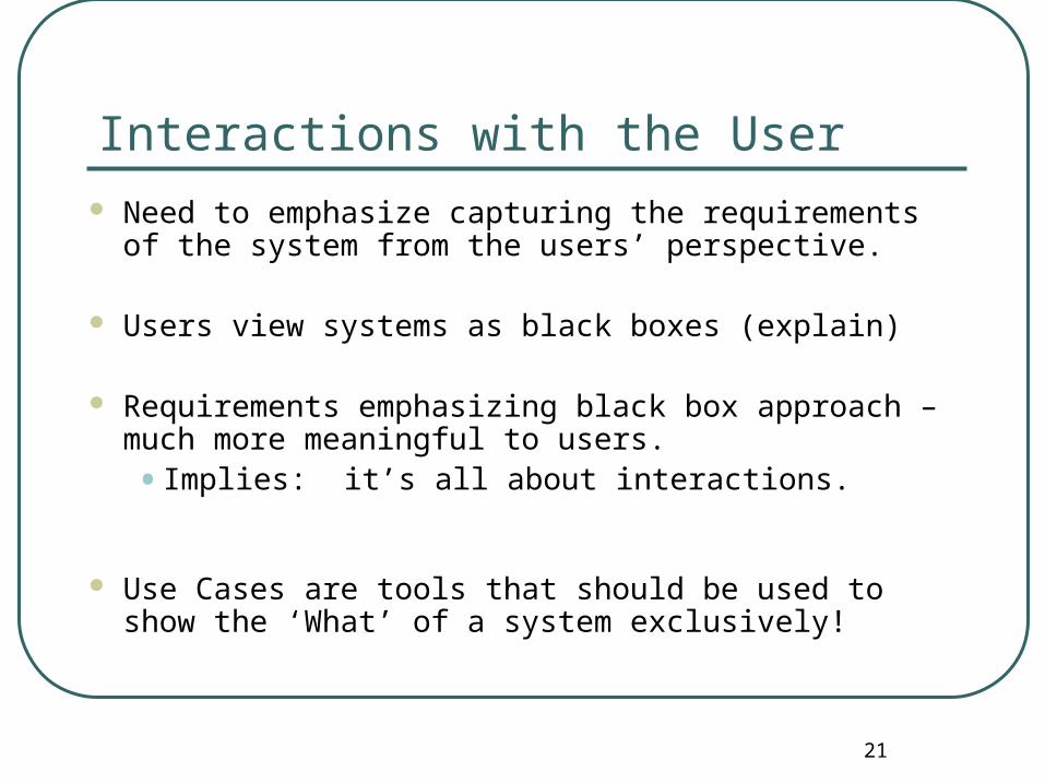
Interactions with the User Need to emphasize capturing the requirements of the
system from the users’ perspective.
Users view systems as black boxes (explain)
Requirements emphasizing black box approach – much more meaningful to users.
• Implies: it’s all about interactions.
Use Cases are tools that should be used to show the ‘What’ of a system exclusively!

22
Hello World Basic Hello World Use Case is a ‘system context’ use case.
Covered later…(Façade Use Case) Use Case – two parts
• Use Case Diagram
• Use Case Description (narrative) Diagram presents overview of important interactions
• Can include in Rational Rose Narrative presents the details of the interactions
• Can include Word Descriptions in Rational Rose via Requisite Pro Use Cases have actors (entities outside the system) interacting with
Use Cases. A Use Case represents requirements often stated in verb-object
format, like Sell Property; stories of user interactions with system.

23
Typical Use Case for Selling Property – Main Use Case Diagram
Buyer
Seller
Advisor
Sell Property
<<communicate>>
<<communicate>>
<<communicate>>
24
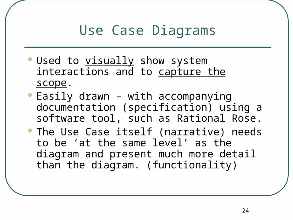
Use Case Diagrams
Used to visually show system interactions and to capture the scope.
Easily drawn – with accompanying documentation (specification) using a software tool, such as Rational Rose.
The Use Case itself (narrative) needs to be ‘at the same level’ as the diagram and present much more detail than the diagram. (functionality)
25
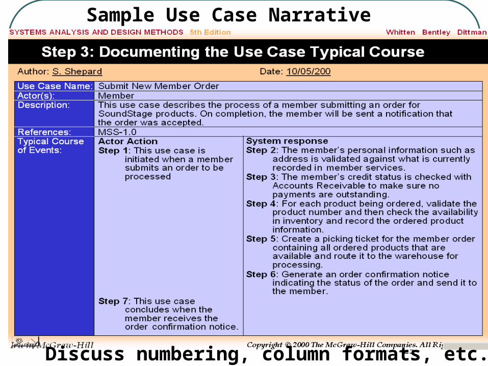
Sample Use Case Narrative
Discuss numbering, column formats, etc.
26
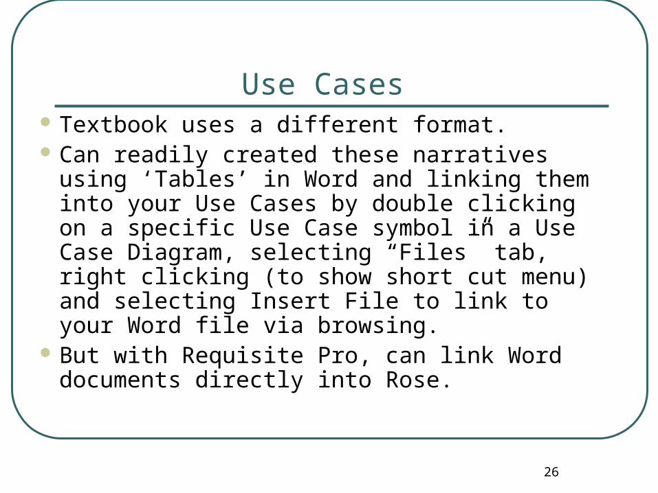
Use Cases Textbook uses a different format. Can readily created these narratives using
‘Tables’ in Word and linking them into your Use Cases by double clicking on a specific Use Case symbol in a Use Case Diagram, selecting “Files” tab, right clicking (to show short cut menu) and selecting Insert File to link to your Word file via browsing.
But with Requisite Pro, can link Word documents directly into Rose.
27
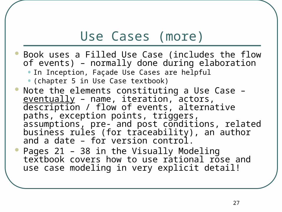
Use Cases (more) Book uses a Filled Use Case (includes the flow of
events) – normally done during elaboration• In Inception, Façade Use Cases are helpful• (chapter 5 in Use Case textbook)
Note the elements constituting a Use Case – eventually – name, iteration, actors, description / flow of events, alternative paths, exception points, triggers, assumptions, pre- and post conditions, related business rules (for traceability), an author and a date – for version control.
Pages 21 – 38 in the Visually Modeling textbook covers how to use rational rose and use case modeling in very explicit detail!

28
Unified Modeling Language Recall: the UML is a ‘notation’ – a way to document
system specifications and interactions. UML is not dependent upon any specific methodology
(process). You need a process WITH this notation!! UML does require that the system has object-oriented
components. Use cases themselves can be used for systems that are
NOT based on object orientation. The UML has nine diagrams that provide different
necessary views of the system. Diagrams are dependent upon each other.
• Changes to one often means changes to another diagram.
29
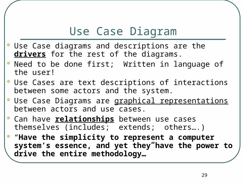
Use Case Diagram Use Case diagrams and descriptions are the drivers for
the rest of the diagrams. Need to be done first; Written in language of the user! Use Cases are text descriptions of interactions between
some actors and the system. Use Case Diagrams are graphical representations between
actors and use cases. Can have relationships between use cases themselves
(includes; extends; others….) “Have the simplicity to represent a computer system’s
essence, and yet they have the power to drive the entire methodology…”

30
Thank you.
Related Documents
![Diamanti Report User Survey 061719 · updating open-source software. [03] EXPANDING USE CASES Container use cases are moving beyond cloud-native applications. Respondents are exploring](https://static.cupdf.com/doc/110x72/5ec394c888b7a70a2e1b61ee/diamanti-report-user-survey-061719-updating-open-source-software-03-expanding.jpg)


