1 1 McCanney Wing Generator TM Distributed Energy National Grid WORLD ENERGY PROJECT With supplement “The Myth of Alternative Energy” By James M. McCanney, M.S. THIS TEXT PRESENTS AN OVERALL DESIGN AND PLAN FOR A WORLD ENERGY SYSTEM BASED ON A NEW HIGHLY EFFICIENT “WING” DESIGN IT PRESENTS A NATIONAL DISTRIBUTED ENERGY SYSTEM WHICH USES OUR CURRENT ELECTRICAL GRID (NO SMART GRID NEEDED) THE FUNCTION OF HIGHLY EFFICIENT WING GENERATORS FOR NATIONAL ENERGY PRIOR MISCONCEPTIONS ARE DISCUSSED - THE 3-BLADE WIND GENERATOR SCAM AND THE FALSE NEED TO BURN FUEL FOR LARGE SCALE ENERGY PRODUCTION jmccanneyscience.com press - ISBN 978-0-9828520-4-0 $49.95US NOT FOR RESALE Copyrights 2006, 2009, 2011, 2014 * TRADEMARKS AND PATENTS APPLY *

Welcome message from author
This document is posted to help you gain knowledge. Please leave a comment to let me know what you think about it! Share it to your friends and learn new things together.
Transcript
1
1
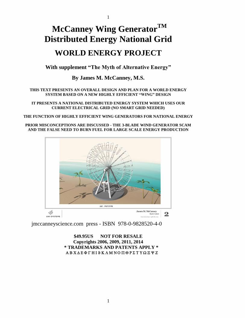
McCanney Wing GeneratorTM
Distributed Energy National Grid
WORLD ENERGY PROJECT
With supplement “The Myth of Alternative Energy”
By James M. McCanney, M.S.
THIS TEXT PRESENTS AN OVERALL DESIGN AND PLAN FOR A WORLD ENERGY
SYSTEM BASED ON A NEW HIGHLY EFFICIENT “WING” DESIGN
IT PRESENTS A NATIONAL DISTRIBUTED ENERGY SYSTEM WHICH USES OUR
CURRENT ELECTRICAL GRID (NO SMART GRID NEEDED)
THE FUNCTION OF HIGHLY EFFICIENT WING GENERATORS FOR NATIONAL ENERGY
PRIOR MISCONCEPTIONS ARE DISCUSSED - THE 3-BLADE WIND GENERATOR SCAM
AND THE FALSE NEED TO BURN FUEL FOR LARGE SCALE ENERGY PRODUCTION
jmccanneyscience.com press - ISBN 978-0-9828520-4-0
$49.95US NOT FOR RESALE
Copyrights 2006, 2009, 2011, 2014
* TRADEMARKS AND PATENTS APPLY *
2
2
McCanney WING GENERATORTM
Distributed Energy National Grid
WORLD ENERGY PROJECT
By James M. McCanney, M.S.
I call the 20th
Century “The Black Century” because its hallmark was filthy polluting energy, the
wholesale destruction of natural resources for false economies and war machines and unbridled
greed. It was blackened further by international corporate rule that held profit as its only measure
of success. Governments of the world were united under a single banking structure that helped
the few greedy leaders in each country to see fabulous wealth while keeping the vast majority of
humans in destitute poverty. The CIA (the police force of the international European banking
devil worshipping cartel) worked behind the scenes creating havoc and terror wherever its
criminal hands touched. In the 21st century the control of world fresh water became the target.
Water and air pollution were sanctioned by the government agencies that were entrusted to
protect them. All aspects of human life in the “modern western world” became shrouded in
governmental agencies controlled by revolving door agents from the industries they were
designed to monitor. Solving the world’s energy problem is at the heart of solving every major
problem on earth. So called solutions such as the “SMART GRID” are fallacies.
The current text is a well documented and well designed system which uses the current electrical
grid system in its current form to distribute energy created by a completely new breed of large
scale high efficiency WING GENERATORS. I have altered the name not to be confused with
the myriad of designs called “wind generators”. The new WING GENERATORS can be
implemented on a large scale to replace one for one the coal, nuclear and other large scale
electrical generation facilities. They can be built as well as medium installations on ranches and
farms for profitable wing generation systems all the way to local individual houses for personal
power production. The concept I call DISTRIBUTED ENERGY also provides for security of the
power system rather than having centralized power only which is susceptible to EMP and other
forms of attack that would neutralize the national energy system.
This book provides an open architecture which permits small scale producers and individuals to
inexpensively create their own local power generation systems but prevents large corporations
from patenting and setting on technology that is needed to free the world from corporate energy
domination. The book also includes a supplement “The Myth of Alternative Energy” which
explains the history of alternative energy and how it has been manipulated and abused including
the 3-blade wind generator scam that has forever tainted the real world of alternative energy.
jmccanneyscience.com press - ISBN 978-0-9828520-4-0 $49.95
3
3
For patent trademark licensing contact the licensing and use department of the
jmccanneyscience group by replying to the email you received when you ordered this
eBook. It contains your customer number which is embedded encoded in this copy of the
eBook. DO NOT COPY this book or distribute to others since your copy is encoded with
your customer number. Any misuse will be traced to your eBook. Due to the constantly
changing situation with patents trademark and copyright protection the conditions of
licensing may change without notice.

4
4
TABLE OF CONTENTS
I. About the Title and Cover Photo……………………….. 6
II. Preface by the Author……………..…………….…12
III. About the Author ………………………………….13
IV. How to Use this Text …………..........………….….20
V. Critique of the standard 3-blade wind generator …..23
VI. The McCanney WING GENERATOR ………….…36 - WING GENERATOR CONFIGURATIONS…………....46
- TABLE OF COMPARISON BETWEEN THE 3-BLADE AND WING
GENERATOR SYSTEM…………………………….…...49
VII. PATENTS –trademarks – open architecture………..53
VIII. SMALL WING GENERATOR DISIGN…………. .62
IX. FAQs (Frequently Asked Questions) ………….…...73
X. DISTRIBUTED ENERGY ….………………….…..75
XI. The Myth of Alternative Energy ……………………77
XII. Batteries and Support Equipment……………………81
XIII. Tesla Power Feasibility ……………..…………..…..83
XIV. Electric Cars and Distributed Free Energy……....…..86
XV. World Domination of Major Industries…………. …87
XVI. Myth of the “Smart Grid”……………………….…...88
XVII. Proposals and prior funding efforts……………….…89 THE Final Statement………………………………………………..105

5
5
OTHER BOOKS AND INFORMATION
BY JAMES M. McCANNEY, M.S. Physics
www.jmccsci.com for eBooks and hardcopy books
Books and eBooks (some available also in Spanish)
Planet X- Comets and Earth Changes
Surviving Planet X Passage
Atlantis to Tesla–The Kolbrin Connection
Principia Meteorologia – The Physics of Sun Earth Weather
Calculate Primes (only available in print version)
The Diamond Principle
Comets
WATER
Breaking RSA Codes for Fun and Profit
CDs and DVDs
2 DVD set – Historical video lectures re-mastered to DVD
DVD lectures series – DVDs
CD – 110 high resolution aerial photos of the American Southwest taken from 45,000
foot altitude from Los Angeles to Denver
2CD set – 18 hours - The Physics of Ancient Celestial Disasters
Emergency Survival Re-Calendar Portable Sun-Star Clock
ALSO AVAILABLE ARE the James McCanney Name Branded water filter line for
sports – travel – home – emergency see the web site below for details
Professor McCanney hosts a weekly radio show heard worldwide on station
WWCR – Nashville, Tennessee
“The James McCanney Science Hour – At the Crossroads”
- See www.jmccsci.com for details

6
6
I. About the Title and Cover Photo
The reason for the higher than normal price for this book is because it is intended for
developers who will be interested in obtaining licensing rights. For those just interested
in another good read you must understand that this book is based on many years of
development and is more than a minor addition to resolving the world energy dilemma.
You are supporting this effort which has cost me personally a great deal of money, time
and other expenses over past years. Making this information public is just a minor
portion of the effort but is important for two reasons. First it protects the work from
greedy corporations intent on securing patents and burying anything real from ever
appearing in the world of alternative energy and secondly it allows for the open
architecture concept where development can proceed under minimal licensing to small
groups who will make a large difference.
The title is important in understanding the full impact of this work. The concepts
presented here are not new but have taken many turns in the long and treacherous history
of trying to bring in new technology online that potentially could solve the world’s
energy problems in a single blow. The history spans a number of decades as I attempted
to present this information to venture-capital groups in technology centers in private
behind-the-scenes only to repeatedly arrive at the same point.
Ultimately someone behind-the-scenes I was working in confidentiality and under
strict confidentiality agreements would try to pass information to a body or secret contact
either in the energy industry, government agency, NASA in some cases or an
unscrupulous company eager to steal ideas which are rare in any industry. Stopping this
and maintaining control of sensitive information convinced me that the only way to
distribute this information was with an open architecture that was available to the public
but also with a certain level of protection to trademarks and patents that would prevent
large corporations from taking it out of commission to protect their other interests. Open
disclosure is a weapon not even patent attorneys of large corporations can battle.
I do not want to dwell on the history of this but it is important for the public
understand the pains that one has to go through in attempt to distributed truly valuable
information that will help the world energy crisis and keep it from the hands of greedy
self-centered self-serving small minded individuals and corporations not to mention inept
crony laden government agencies.
The title depicts an entirely new concept in the world of alternative energy using the
word WING rather than the traditional term “wind”. There are many myths that abound
in the alternative energy industry especially in the field of energy generation by wind.
Ultimately the aim with any alternate energy project must come down to a single
criterion. It is not profit or financial stability, it is not government grants or subsidies, it
is not a presidential directive nor selling off-shore wind rights to companies deep in the
back pocket of high level government officials and most of all it is not related to the
companies that promote “green energy” alternatives like GE or SIEMENS who have
7
7
vested interests in large scale technologies like nuclear and who have absolutely NO
INTEREST in the success of alternative energy solutions.
The single and only criteria that one must use when examining any alternative energy
“solution” is … “can it create with a reasonable economic investment the sum total
amount of energy we use daily on planet earth which includes nuclear – coal – oil (and its
derivatives) – natural gas”. PERIOD END OF DEBATE. If you look at the sun total of
research programs that have been funded or the government approved projects to date for
alternative energy, not a single one of them passes these simple criteria.
There is a myth that for large scale power one has to burn high energy content fuels to
create electrical energy. One thing that this book will accomplish is to break that myth.
Simply put, the horrendous pollution, the burning of oxygen which is the life molecule of
our planet, the aftermath of nuclear waste not to mention the mining and processing and
transportation of these “fuels” are only part of the problem. The greater problem is that
these heat to electricity to distribution to end use (light – motors – industry – etc)
processes are horribly inefficient (horribly is putting it mildly).
Of the so called mega projects that have sprung up for solar and wind and wave
conversion to electricity, NONE of them even come close to fulfilling the single criteria
that must be met in any alternative energy project and this should have been clear long
before the first penny was spent on any of them. But the single main criteria has never
been uttered by anyone in the industries who have capitalized on government incentives
to make a buck out of technologies that could not possibly make a difference in the world
of “green energy” and which could never be profitable on their own.
People drive electric automobiles with pride beaming that they have a green vehicle
and falsely parade statistics that they have wonderful gas mileage. They fail to
understand that the amount of electrical energy that comes either from nuclear or coal
burning electrical plants coupled with the inefficiency of heat conversion – distribution
inefficiencies and then conversion to battery which in turn is reconverted to electricity is
astronomically more polluting than just burning the gasoline in the engine in the first
place.
We live in a world of misconceptions and unfortunately the western mind has a
property that once it adheres to a belief it is almost impossible to pry it out of the
disoriented cerebral memory slot. There is actually a chemical in the brain which turns
on when contradicting information is processed in the brain which prevents alternative
knowledge to enter and be processed. I call this the “university professor syndrome
enzyme” or simply PhDitis. Most university professors live by what they learned 20
years ago in a text book. I call them text book repeaters or text book geniuses; repeating
what they were taught in a sing song matter and receiving a hefty pay check for their
“work”.
Unfortunately the general public is no better. How many people repeat without
questioning “global warming” or global climate change” without ever understanding that
this has been a complete hoax actually driven by people who use it to divert real attention
from the real issues of stopping nuclear – oil – natural gas – coal from continuing as our
main source of energy. Once again, university professors eager to secure grant moneys

8
8
will repeat this until the fat woman sings as long as it gets them closer to retirement and
keeps their tenure and publication string going. The simple solution is that we simply
cannot continue burning high energy content fuels for energy. That simple solution is
never discussed as the topic never arrives at that table because of the political football of
“global climate change”.
There is a myth that we must produce and use the amount of energy we are
consuming today to drive a false economy and the unsung pig of energy usage the US
military (which singly uses over 70% of the daily energy consumption of the world).
Along with this is the other great myth that people need a 40 hour a week job to pay for
outrageous interest on loans for vastly overpriced housing, automobiles and credit for
almost everything else in their existence.
Yes there are many myths that have to be overcome before the public really
understands in context the complex solution of the energy dilemma in the world today.
So in beginning at the bottom and designing a world energy plan including equipment
that will truly solve the world energy problems I had to first understand the multitude of
problems and myths that surround the energy crisis. I had to intricately understand the
current electrical grid and I had to understand the complexities of the alternative energy
industry that exists today. I had to understand the fallacious efforts such as the so called
“Smart Grid” and other efforts meant to mask the hidden agendas of the politicians
pushing these agendas. I had to start at the bottom and examine the current status of wind
and solar energy production and I had to redesign the heart of the new systems that would
set the new paradigms that will last into the future. The solution had to be economically
feasible and it had to replace on a grand scale the systems that were in existence today
not only in the developed world but in the second and third worlds.
Some years ago I began a project (noted on the cover of my home internet page) to
develop a full scale Tesla Tower which had as its original intention the ability
(discovered by Tesla) to extract energy from the vertical electric field of earth by tapping
into the earth to ionosphere “capacitor”. In a chapter in this book I will discuss this in
detail (the physics of this topic are discussed in my prior books). But my project was my
first effort to solve the world energy situation with naturally occurring energy capture.
However I ran into a few small problems that convinced me that this form of energy
production was not practical for commercial use. First of all, the tower would be
attached to the public grid. Second of all, once the naturally occurring energy and
electric current began to flow like a vast river from outer space to the electric grid, if we
ever experienced a solar storm or other form of atmospheric EMP (electromagnetic
pulse), there would be no practical way to stop that current flow from emanating out into
the public grid.
Simply doing experiments with something on his grand scale would be very difficult
because you do not simply produce a small amount of power. Once you tap into this
enormous cosmic capacitor and the current begins to flow there is no way to turn it off,
just like a massive dam that just broke sending a cascade of water down the mountain
valley to destroy everything in its path. Tesla technology was not the solution. Someday
there may be a use for Tesla technology that would extract energy from the vertical

9
9
electric field of this planet or possibly another. Just experimenting with it posed
severe physical constraints. One needed an entire city as the power sink for the energy
and this was simply not available. Wind however was a different story as it could be
tested and controlled. We understand wind and deal with it every day. It is abundant far
beyond our energy needs. Just an extremely small portion of it will power all of our
needs for world energy and it blows day and night all over the world. There is no place
or time that is devoid of wind for more than a few hours.
One has to understand that wind also is a form of electric power. There is a
misconception in the world of meteorology that wind is somehow caused by solar light
that comes into our atmosphere and heats which in turn causes atmospheric flow and
therefore winds. I also talk about this later in this book and of course it is the main topic
of consideration in my previous works and books (see prior booklist at the beginning of
this book). The true cause of wind on planet Earth is due to electrical currents that flow
by our planet every day. The major wind systems which we call jet streams are charged
flows of atmosphere that are literally coupled to the magnetic field of earth. There are so
many contradictions in the standard “solar light causes weather” story that this book can
only reference the major ones discussed at length in the other earlier books by this author.
The major result is that WIND is another manifestation of the electrical nature of our
world.
Wind is available in certain places more than others and on the ocean it is steady and
available all the time. The only problem is that the wind generation technology that has
been implemented to date is terribly inefficient and woefully short of making any
significant contribution to the single important criteria of making a dent in the world
energy consumption needs. I have given many radio show interviews and lectures to the
public and professionals in the electric industry as a private consultant. One of the most
telling results is that it would take over 77 million of the 1.5 megawatt 3- blade
commercial wind generators (like you see dotting the landscape of Europe or the central
plain states or other areas of the world) … yes it would take over 77 million of these to
begin to approach the world energy needs IF THEY WERE WORKING. The problem is
that most fall idle shortly after installation and produce little or no energy at all.
This vast failure I contend was a planned failure coordinated to keep the green tree
huggers and alternative energy glossy magazines occupied thinking that “green energy”
was upon us when in fact nothing would be farther from the truth. Belgium, a country
desperately in need of alternative energy, recently passed a law banning wind energy and
government subsidies of wind energy. Recent studies of field results from England, the
Netherlands and other countries that made significant investments in alternative wind
energy systems (investing in the standard 3-blade wind generator designs) all came to the
same conclusion that they were a huge waste of investment and that they had been sold a
bill of goods that never could produce. The problem was a control of this industry by
companies that were interested in making a quick profit and sold these systems claiming
peak operating capacity of the 3-blade wind turbines when the reality was that they could
only produce a maximum of 15% of capacity on average IF THEY WERE
OPERATIONAL. Within a year of installation the majority sat idle with technical

10
10
problems and the companies who installed them started the finger pointing game and
left these countries holding the bag.
A supplement included in this book is called “The Myth of Alternative Energy” and
discusses the history and deception of the alternative energy industry. It is a must read to
understand why the WING GENERATORS presented in this book are not called “wind
generators” because they have to stand apart from the previous generation of scams that
were generated based on the original non-functional design that was initially developed
by none other than NASA.
The simple solution is that there is a solution. The solutions must come from
engineers who have engineering solutions at heart (like in the early days of the computing
industry) and who design for efficiency and not the objectives of politicians or their crony
corporate buddies or the profits of government subsidies and poorly managed
government regulatory agencies.
This book presents the solution and at the heart of it is an electrical generation system
that can be scaled from the small home user to midsized installations on farms and
ranches to large scale systems that can rival the energy production of nuclear power
plants and all at a cost which is reasonable. Once the initial installations are made the
only cost will be the upkeep of these relatively simple devices. The other half of the
system is what I call DISTRIBURED ENERGY where the individual can invest in a
piece of the energy production facility (like owning stock in a company) and additionally
may have a small generator at their house. The individual would also possibly have a
distributed storage battery system in their home that would store a few days worth of
electrical energy and this would become as common a home appliance as a water heater
or kitchen stove complete with inverter to convert to electric wall A/C power. Along
with this is the reduction of usage and the more efficient use of the electricity we
produce.
The cover photo is page 2 of a set of drawings that were produced in 2009 as part of
one of my offshore venture capital procurement efforts which ended in failure as
someone got to the private investors behind the scenes. Depicted is a beach setting which
was our plan at that time to build the 100 prototype models on a remote stretch of private
beach in Mexico. The other prints from this proposal including the full written proposal
which was all handled by myself personally as I travelled to remote areas of the
American southwest to meet with the financiers are included later in this text. The
prototypes were designed to be 100 feet tall and we planned to make the first
commercially available models 200 feet tall. The next round of investment was to the
next level with a 500 foot tall model and finally we would go to the final size of the full
scale 1000 foot tall model capable of producing the equivalent of a full size 500
MegaWatt nuclear generator. I had the OK on the engineering end of the project from
my private contacts that these were completely feasible to construct on this scale and my
own work involved the physics and engineering of a system that could consistently
produce this level of energy even at lower wind speeds unlike the 3 blade predecessor
“wind turbines” that at most would put out a few megawatts of electricity on a good day
and possibly only one tenth of that on an average day.

11
11
Remember this was in 2009 and a prior project met the same fate in 2005 when I
had an international engineering construction company and financiers set to build the
small scale roof top WING generators for industrial applications. In this case we were
completely ready to go into development and construction of the first prototypes when
we needed the final signature of the president of the company. I had the company and all
employees as well as the financiers under strict confidentiality agreements which
specifically prevented them from contacting anyone in government or industry while we
were in development. At the last minute the president of the engineering company that
would be doing the installations decided he “had a buddy at NASA who he wanted to
review the project” and that is where it ended. It in fact was NASA that had developed
the fiasco 3-blade wind generators in common usage and it also was the same NASA that
was famous for stealing ideas of unsuspecting engineers and developers and integrating
into their programs to give credit to their staff and squeeze out the original designers.
Yes that is where that effort died.
The reality of dealing with people in industry and government and in the world of
venture capital is that they simply do not know who is making the world go around and
who is in control. They do not understand that alternative energy programs are only
permitted if they have no hope of solving any problems and which have no capacity to
truly replace the major forms of energy production now in common use. They do not
understand that if word of a real program that truly can make a difference gets to the
wrong people they are putting the lives in jeopardy of everyone associated with the
project. Once again I can only come to the conclusion that I have to release this
information to the public in the manner of this book with limited licensing open
architecture that encourages small entrepreneurs and local home users to produce their
own electrical systems at minimal costs while preventing large corporations and
government agencies and politicians with agendas from getting their greedy hands on it.
.
12
12
II. Preface by the author
Breaking paradigms is not easy. Breaking corporate rule on monopolized industries
is even harder. Redirecting controlled politicians is nearly impossible. But breaking the
back of the world bankers with their control on energy – war – money (the root of all
evil) – water – and the list goes on and on … yes breaking the back of the international
bankers would be the nigh most impossible task on planet earth. Yet if done it would
solve the majority of world problems. The rest we could solve with good old fashioned
love and caring, something that has been lacking in the world for a very long time.
I am going to give a list of projects that I am working on in a later chapter including
the current topic of energy production and distribution to replace the current world
energy sources. The end result is what I call “FREE LIVING”. The scams that have
been placed on top of the public and the associated burdens are now beyond measure. I
remember 50 years ago listening to one of the international bankers front men named
Henry Kissinger talk about peace talks in the Middle East. That was 50 years ago and
guess what … he is saying the same thing today as this book goes to press. There have
been no solutions nor will there ever be a solution. This is the world “game”.
If you look closely the dog and pony show of international politics, it keeps the
international control of all countries in the hands of the few … the European bankers.
They control science and engineering also as I have stated many times in my previous
work. Before you solve the world energy problem you have to understand that there are
some very powerful people who hold their power because of the control of energy and
they have been at this for a very long time. The majority of strife throughout the world
over the past 100 years has been due to energy procurement and control. So producing
an energy solution that will replace the current world energy management establishment
is only a very small portion of the problem. There are some very powerful people with a
long list of hired thugs who have no intention of letting something like this happen.
When I released my book “Calculate Primes” I was fully aware that it was not just the
solution to and age old mathematical problem. It also broke the public key encryption
codes that were used for secure computing. This caused and avalanche of disasters in the
computer world which are continuing to this day. Because I knew this before I released
the book I had to protect myself as I had worked in the industry of secure computing at
the professional engineering level for about 25 years of my private career. 10 of those
years were in the design of high level secure telecommunications computers used by
banking and industry. So I knew in advance of the problems that I would face in
releasing that information.
The current release is even more risky as it involves resolving one of the most
controlled substances on the planet … energy. The field is so complicated that few have
even a reasonably close to reality view of the truth. Many believe for example that we
have reached “peak oil” and that the future of oil is higher costs and higher gasoline
prices. The reality is that there is so much oil (and readily available oil at that) that we
have far more than we could every use. The problem is that if the public knew that the

13
13
cost of oil would not be controllable as it is today. Secondly the real truth is that we
cannot continue to burn oil at the rate we are burning today because we are literally
burning up all the oxygen in the atmosphere. We have 50% of the oxygen that the earth
had in the early 1900s before the industrial revolution. But you will never hear any
“Global Warming” experts talk about that. They will only talk about getting another
grant to do another 5 years study where they can fudge the data to get the next
government issued grant. The federal government (the middle management of the world
banker control network) will not tell you that because the real reason for “global climate
change” policy is to create more draconian laws to control the public and especially
WATER (see my recent eBook WATER for details).
There is a myth that oil comes from dinosaur bones and decayed fern forests. Oil is
found all over the world including at the basins of the deepest oceans and some core
deposits are over 20,000 feet below the surface of the earth (below the base of the
oceans). How did the fern forests grow there captain hook? The real issue of where oil
comes from is clouded in more mumbo jumbo fairy tale science that is pawned off on the
public everywhere from kindergarten to the daily newspaper to the History Channel or
National Geographic specials.
What I do on my weekly radio broadcast (commercial free heard worldwide on the
most powerful radio station in the world WWCR Nashville, TN – USA) is to
communicate the fallacies in standard science but also to replace it with real science that
you can understand. You do not need a PhD to understand real science. It is very
understandable from a basic point of view and everyone can see the details. When you
understand where energy comes from and the myths that have been propagated to the
public you can start to turn the corner to truly understand the methodology to replace
what is being handed to us today.
But with respect to the WING GENERATOR systems here is what is going to
happen. This is an open architecture with a feedback loop. Many people are
knowledgeable in the use and technology of alternative energy. People will start building
and altering and feeding their discoveries and improvements back into the system and
others will do the same. This is not like a traditional engineering project done in secret in
a laboratory of a company set on filing the patents and protecting from anyone else using
them. Within a few years the avalanche of developments will break the bond of
expensive alternative energy and we will be able to start replacing the larger scale
systems up to and including large coal and nuclear systems that are now the heart of the
national power generation system. As this goes to press I have been told that the battery
division of the Tesla Automobile company is going to produce large volumes of batteries
that will drive down the cost of batteries which can also be used in the home setting as
well as in electric automobiles. Musk the leader of the Tesla Company has opened up the
patents they hold on battery technology for anyone to use. Could we be heading into an
era where individuals with foresight are redirecting the future of energy … how it is
produced and how it is used in our daily lives?
jim mccanney
14
14
III. About the Author
James McCanney is known worldwide for his research and books as well as radio and
lecture appearances dealing with the electrical nature of the cosmos. What many people
do not know is that he is also a Mathematician who has worked on and solved some of
the more complex problems of Physics and Mathematics, and is an expert in computer
design, solid-state physics, telecommunications and computer protocols.
He has worked about half of his lengthy career in private industry, owning several of
his own companies and also taught at the University level in Physics, Mathematics,
Computer Science and Astronomy. Much of this was accomplished in multi-lingual
settings, having worked in the USA, Latin America and with high-level Russian
scientists. He has presented his findings at numerous international conferences and is a
regular presenter at American Geophysical Union meetings. He has presented his
theoretical research in locations such as Los Alamos National Laboratories, International
Air shows and International Electric Propulsion conferences. Understanding his
background is important in placing the current text into perspective.
James M. McCanney, M.S. received sound classical physics training at St. Mary’s
University (Winona, Minnesota) receiving a Bachelor of Arts degree with a double major
in Physics and Mathematics in 1970. He was offered full scholarship awards to three
major US physics graduate schools to pursue his graduate physics studies. However, he
chose instead to postpone graduate studies for a period of three years while he traveled
and taught Physics and Mathematics in Latin America.
During this time he spent a good deal of time traveling to ruins of ancient cities and
archeological sites, studying firsthand many times as the ruins were dug from under dirt
that had not been moved for thousands of years. Also during this time he developed the
basis for his theoretical work that would, at a later date, deal with the celestial mechanics
of N-bodies and plasma physics, as well as the groundwork for the current treatise on
prime numbers.
He has stated that in his travels he learned that nature provides elegant yet simple
solutions to even the most complex problems, and that she reveals these fundamental
secrets to only those who pursue truth for truth’s sake, without the encumbrances of
modern life or economic rewards that so many times cloud the visions of humans,
especially scientists, most of whom are entrenched in the age of big business and
government monopolized science.
With this new understanding of archeology, astronomy of the ancients, physics and
the world around him, Mr. McCanney returned to graduate school in 1973 and earned a
Master of Science degree in nuclear and solid-state physics from Tulane University, New
Orleans, LA. His research involved a National Institute of Health research grant (in
conjunction with Gulf South Research Institute) to study visible light and x-ray sensitive
photo polymers to be used in medical Xerox x-ray machines. The results of his research
resulted in patented discoveries. He was again offered a full fellowship to continue on
with Ph.D. studies, but once again he declined and returned to Latin America to study
15
15
archeology and teach Physics, Mathematics and Computer Science in Spanish. He
continued his personal work to explore the mysteries of celestial mechanics and its
relationship to the planets, moons and other celestial bodies.
At this time a fellow Ph.D. at Tulane wrote in a letter to a professor at another
University, “the first observation that comes to mind concerning Jim McCanney is his
unusually broad range of scientific and intellectual interests. His mind is a veritable fund
of information and ideas on topics as varied as Egyptian pyramids and the classification
of mushrooms. His character and morals are of the highest caliber. He possesses an
excellent aptitude for design and construction of research and measurement systems as
well as a creative bent in understanding and explaining observed physical processes. He
is able to engage in significant research with little or no direct supervision. His research
experience is such that he could involve undergraduates with minimal outlay of funds.
He has the ability to command respect of those in his classes and is able to generate an
unusually good rapport with students.”
After four years living and teaching at the university level in Latin America, in 1979
Mr. McCanney joined the faculty of Cornell University, Ithaca N.Y. as an introductory
instructor in physics. It was during this time that he had access to NASA data returning
daily from the Voyager I and II spacecraft as they traveled by the planets Jupiter, Saturn
and beyond (as well as data from many other space craft). It was here he recognized that
the mathematical models in his theoretical work regarding the electro-dynamic nature of
the solar system and universe had its signatures in the new data that was streaming in
from the edges of the solar system.
His papers were published at first in the peer reviewed astrophysical journals, but
soon he began to receive resistance from the standard astronomical community. Mr.
McCanney was removed from his teaching position because the standard scientific
community did not accept his beliefs regarding the electro-dynamic nature of the solar
system, beliefs that are just now becoming the basis for modern Space Science and
Astrophysics.
His innovative theories on plasma physics and a new model for fusion in the solar
atmosphere provided the basis for the electric fields and plasma discharge phenomena
that have become the core elements of his theoretical models of the true nature of the
solar system in which we live, and which are the fast becoming the basis for every
international conference on space weather and space physics.
Upon being removed from the physics department for his then radical beliefs, Mr.
McCanney was rehired shortly thereafter by the mathematics department also at Cornell
University, where he taught for another year and a half and continued to publish his
papers in peer reviewed astrophysical journals. Again astronomers coerced his removal
from the Mathematics Department and ultimately he was blackballed from publishing in
the astrophysics journals in1981.
His first peer-reviewed paper in 1980 “Continuing Galactic Evolution” (written while
he was in the Physics Department but published while in the Mathematics Department of
Cornell University) advanced a new technique for solving simultaneous differential
equations for the orbits of stars in a galaxy. It is said that only a small handful of people
16
16
in the world understood the significance of this short but important paper. With a
second paper “Saturn’s Sweeper Moons Predicted”, he was, according the department
chairman at the time, the only Cornell Mathematics Department faculty member ever to
be published in the peer reviewed astrophysics journals.
During this time Mr. McCanney established himself as the originator of the
theoretical work regarding the electrical nature of the cosmos for which he coined the
term “THE ELECTRIC UNIVERSE”, which today is being proven correct on an ongoing
basis by space-probes returning data from outer space. Many of his predictions such as
x-rays to the sunward side of comet nuclei, that comet nuclei would be found to have no
ice or water frozen on their surfaces and that comets interact electrically with the Sun as
well as solar electrical activity affecting Earth weather, have now been confirmed by
direct measurements in 1986, 1996, 2001 and 2002 to the present day. Many other more
abstract concepts have also been verified.
After the Cornell years Mr. McCanney worked in the telecommunications industry as
a Principle Systems Engineer at a major telecommunications corporation designing
computer telecommunications equipment, and also ran a number of his own companies
dealing with satellite communications and electrical propulsion systems. He attended and
spoke at numerous international conferences on the future of space flight using his
designs of electro-magnetic propulsion.
It was during these same years that he continued to interact with the scientists at Los
Alamos Labs and Goddard Space Flight Center during the era of the first comet fly bys of
comets Giacobini-Zinner and Comet Halley. Throughout the years and the decades, he
has always remained an Independent Scientist, never using government funding or
positions to further his personal research.
In the mid-1990s Mr. McCanney’s work was recognized by a group of high-level
Russian scientists at the University at Novosibirsk who had measured but did not
understand electro-dynamic effects around Earth and in the solar system. Upon
discovering Mr. McCanney’s work, they translated all of his papers to date into Russian.
These are still being taught at the university level as the leading edge of research in this
field. It is only due to the ongoing and intentional efforts of NASA that his work has
received such little attention in the western scientific community and press.
In the background Mr. McCanney continued working on the illusive mathematical
problems facing celestial mechanics, that is, the unknown method of solving
simultaneous differential equations. He believed that nature had provided a simple but
elegant method to solve these complex problems that did not exist in current
mathematical capabilities. He envisioned a mathematical technique that would be
applied and reapplied to generate a final solution. In this respect, many unsolved
problems of mathematics and quantum mechanics and even genetic molecular structures
would have their solutions in this new mathematical technique.
His search lead to a technique that is the basis for the discovery of the solution to the
prime number problem presented in his book released in 2007 “Calculate Primes”, and
which now holds promise at solving some of the great mysteries of Quantum Physics as
well as Genetics. It is based on the “Mathematical Operators” that the Professor calls

17
17
“Generator Functions”.
These mathematical expressions operate on fundamental units or building blocks of
nature such as the numbers 0 and 1 (as in the case of the prime number solution in this
book) or atomic nuclei (in the case of quantum mechanics) or atoms and small molecules
(in the construction of large organic molecules or genetic structures). According to Mr.
McCanney, “the Generator Function is an operator that reflects conditions in nature, it
builds up a first layer when applied to the basic building blocks, and then is applied to
this construct to form a second more complex structure. The same Generator Function is
then reapplied to this result and the process continues, with each successive application
modifying the prior set of results”.
This leads to questions that are being asked for the first time. For example in
genetics, could the makeup of the human biped be not only duplicated somewhere else in
the universe, but is the norm rather than the exception based on “Generator Functions”
that operate on the building blocks of life. Could this pattern be replicated on the far side
of the universe just as a diamond would appear the same in such a distant place?
On a simpler note, as the prime numbers would be discovered by intelligent beings on
the far side of the universe, they would follow the same mathematical Generator Function
that we would discover here on earth. The implications of this new mathematical
technique may someday very well overshadow this initial application and the discovery
of the formula for directly calculating the prime numbers to infinity as presented in this
book and DVD lecture (Appendix I contains the original mathematical treatise). All of
Mr McCanney’s books CDs DVDs are only available on his internet web page along with
all of his archived radio shows at www.jmccsci.com .
An essential aspect of the Generator Function concept is that it creates intermediate or
“false” solutions that are necessary steps to generate the final correct solution. This is
possibly but one of the reasons why so many mathematicians have worked around the
prime number problem without finding a solution, as they failed to see the total picture as
presented in this book. Countless mathematicians have come to the conclusion that that
prime numbers are random with but passing patterns. This book proves that to be
incorrect. When you finally look at the prime number table and see why every number is
there and how it is related to all the other primes, with all of their “ancestors” bridging
back to the numbers 0 and 1, you will understand the powerful impact this book will have
on the future.
This is a brief but incomplete history of the background that makes “The Professor”,
as many people call Mr. McCanney, a person with a unique background and
qualifications.
Mr. McCanney airs a weekly radio show “The James McCanney Science Hour – At
the Crossroads” heard world wide on short wave radio and also broadcast on the internet.
He has been a popular regular guest on many national and international radio shows.
Most people know of “The Professor” from his work regarding the electrical nature of
outer space and its relation to our planet and human beings that inhabit our blue planet.
He has worked over his career on the current topic of the prime number solution and
has taught the following mathematics courses at the University level (in addition to
18
18
Physics, Computer Science and Astronomy); Abstract Algebra, Linear
Algebra, Matrix Algebra, Probability and Statistics, Statistics for Computing,
Mathematical Logic, Theory of Numbers, Calculus I, II and III, Engineering Math I and
II, Advanced Topics in Geometry and Topology.
He has been an avid student of the history of both Physics and Mathematics and has
studied the past to understand what is of greatest importance in the future of these fields
of study. The present book is a glimpse into this rarely seen side of Professor McCanney.
He has stated that his greatest discoveries to date include the cause of surface fusion on
the sun, which gives rise to the solar electric field that drives the electrical nature of the
solar system. His second great discovery, which was published almost 2 decades before
its discovery, was the prediction that comets would produce x-rays far to the sunward
side, as well as the electrical nature of comets and the prediction that comet nuclei would
not contain water or ice, but would be hot dry asteroid type bodies (a prediction that has
repeatedly been proven by subsequent space probes), much to the surprise of professional
astronomers.
A third major theoretical discovery, which has been observed both in nature and
subsequently measured in the laboratory, he calls “The Induced Electric Dipole Red
Shift”. This is an effect on photons of light moving through a non-uniform electric field
that causes both a red shift as well as a bending of light. It also explains the previously
unknown cause of pair production (electron-positron production) in photons passing near
heavy atomic nuclei. His theoretical work then restructures the laws of cosmology based
on this new form of red shift.
And last but not least, his work has rediscovered the work of Tesla and further
provides a theoretical basis for deriving unlimited electrical energy from the ionosphere.
Another result of his decades of research has been the realization that severe earth
weather including hurricanes and tornados are powered by electrical discharges from the
ionosphere to the clouds in storm systems. The list of scientific discoveries also includes
an electromagnetic propulsion system for use in space travel that has been field-tested.
In spite of these discoveries that were confirmed in many cases decades after Mr.
McCanney’s theoretical predictions were published, he now has stated that the treatise on
prime numbers potentially may have the greatest significance in the history of both
Physics and Mathematics. The solution of the Prime Number Problem has eluded every
great mind since the Greeks first defined it nearly 2500 years ago. Cauchy, Gauss,
Riemann, Euler, and countless others spent their entire lives scouring this problem, yet
could not crack the fundamental problem of being able to directly calculate the prime
numbers. Countless major unsolved problems in both Physics and Mathematics base
their solutions on the prime numbers, yet no one could directly calculate these illusive
and perplexing numbers, that is, until now.
The current text “McCanney WING GENERATOR” is the culmination of many
years of perfecting the solutions of the WING designs which are presented in this book
coupled with the decision to release it as an open architecture directly to the public. It not
only creates a new family of energy generator products which are scalable but
furthermore shows how to incorporate them at all levels into the current electrical grid
19
19
structure. This would be a major achievement but the most important aspect
of this family of designs is that it is affordable and radically reduces the cost of energy
production. It is a true alternative energy solution that can be produced by the individual
all the way up to large scale systems that will replace one for one the large heat
conversion electrical systems based on nuclear – coal - # 2 fuel oil – natural gas. The
system can be used on boats and automobiles directly driving these mobile devices
wherever there is wind. It could be used for direct powering (without conversion to
electricity) of everything from hydraulic or compressor based systems in factories or to
move water on a large scale from flood high water areas to drought stricken areas of the
planet. It can be used on converted oil tankers that we can convert to water carrying
tankers which can use direct WING power to move them from areas like Antarctica or
Greenland melting ice fields and take the fresh water to areas where the water is needed.
WING systems can be used to directly drive desalinization plants in remote areas without
electricity. Direct powering of factories using WING power as assist to electrical power
will cause a huge savings in electrical power requirements of factories which accounts for
a full one third of all electrical power consumption in the industrialized world.
With the reduction of lighting consumption with modern LED or equivalent bulbs
another one third of energy consumption can be drastically reduced. If we use less
energy by making wise choices then we have to produce less energy. By storing energy
at the household level we also increase security of the energy resource and reduce the risk
of national energy terrorist or naturally occurring EMP attacks.
a.s.
.
20
20
IV. How to Use This Text There is a wide variety of people who are going to read this text but can be divided
into two basic groups. Those who are just trying to be informed and those who want to
build and make workable models. This book is partially educational so you have a firm
understanding of the alternative energy industry as we see it today and how it arrived at
the current state. Everyone should learn this and especially if you are interested in
building the open architecture systems.
First I have to present what is the standard caution in any industrial situation whether
you are baking a cake or hang gliding in the mountains. If you do not know what you are
doing, or even if you think you know what you are doing, anything you build is at your
own risk. With any technology there are risks. In the case of wind energy you are
dealing with lethal amounts of electrical currents. You can encounter strong winds or
gusty winds and no matter how well built or well planned your construction, at some
point all systems will fail.
That is why I do not present step by step “cookbook” plans in this book. I present
designs that YOU THE USER will take and make into your own creations based on your
abilities and available materials. As a spoof I made a WING GENERATOR out of
primitive materials. I used naturally occurring magnets (you can purchase at any rock
shop in the American west) with wire created from poorly refined copper ore to create the
generator (alternator). I used dried palm tree branches (fallen to the ground from trees on
the beach) and the hub I made from a section of palm trunk. Lubricated bearings were
made with coconut oil and the sails and support ropes I fashioned from woven husks of
the coconuts (just like ancient Polynesians used to make their sails on the ocean going
canoes). This primitive set up worked to create electricity.
Out of this concept of “open architecture” including the feedback loop from you the
people working in all directions we will together create and engineering set of design
parameters that will help others build more efficient and stable WING GENERATORS.
The concept of “open architecture” is new to an industry bent on corporate ownership of
patents ready to sue and defend anyone in courts to keep their market share. A separate
chapter in this book deals with the concept of patents. My philosophy is somewhat that
of the famous book during the 1960’s “STEAL THIS BOOK” by Jerry Rubin which dealt
with the social illnesses of the United States during the height of the Viet Nam War
fiasco.
Clearly I want to have my name attached to the introduction of the WING philosophy
and design innovation along with profits that will allow me to continue research, but I
also want every person on the local level to be able to build and create a system and then
provide feedback information so that all people can benefit from the combination of
innovation. Additionally I have discovered from my history of dealing with this topic
that the road to success is fraught with road blocks all the way to the top of the world
banking cartel. REAL innovation is not allowed. Anything you see in the alternative
energy market is allowed because 1) it is relatively expensive for the amount of energy
21
21
you will receive and 2) it will not match the single criterion necessary for any real
contender in the alternative energy market (that it can truly replace the large scale heat
conversion systems that power our world today and which keeps the public energy
dependent on large corporations ultimately controlled by the central European banking
cartel). With that in mind read the chapter on patents which includes the licensing of the
WING GENERATOR.
When I was young I worked for a short time as a fishing guide at a resort in the
northern woods of Minnesota’s wilderness country. My mentor told me that when
handling boats or canoes or other equipment of customers to always have them keep at
least one hand on their equipment. That way if something happened they had their hand
on it too. The same holds true for electrical systems. This is not like baking a cake or
buying a UL approved product that has had extensive UP approval ratings so the
complete home idiot is safe. With the WING GENERATOR technology you will be
forging your own new ground in a sense. Remember I could have produced products and
sold them in the mid-scale commercial market to make a LOT of money rather than
release this book, but the extensive UL approval testing is prohibitive to get a new
potentially dangerous product on the market. Besides, if it ever had a chance of creating
an energy revolution it would be bound up and prevented from seeing the light of day and
could more easily than not cost me my life.
The designs here are meant to direct you. My personal designs for example use only
plastic and light weight synthetic materials. They are extremely light weight. But you
can take the same design and build it with stainless steel if you like or heavy canvas or a
combination of various materials. Kids could make small models out of cardboard and
string and light weight plastic tubing.
Another major consideration was to take existing wind generation systems (the 3 or
multiple thin blade designs you commonly see on the market today) and convert them to
the new WING designs. This is discussed in the text. The major scale 3-blade wind
generation systems around the world eventually will have to be taken down. A single
pole is not the best configuration for the WING GENERATOR designs but I had to take
this into consideration so I developed a way to at least salvage the use of the central
column from the existing 3-blade systems and convert to the WING design. My
estimate is that a 1.5 megawatt 200 foot 3-blade wind tower that only produces about
150,000 watts (one tenth its rated capacity at low wind speeds) could be converted to a
WING GENERATOR system to produce 8 to 10 megawatts on a consistent basis
including lower wind speeds. At least the countries of Europe who have egg all over
their faces from recent 3-blade wind generator fiascos can salvage and regain their losses
over time. Unfortunately all of the hardware in the tower will have to be discarded since
the generators are far below the energy production capability of the WING designs for
the equivalent size system.
We have seen other industries suffer the same fate. Remember a number of decades
ago the large backyard satellite antennas? I actually had a small business at one time
selling these along with MACOM satellite receivers. I also knew and talked to Stanley
Hubbard (owner of the Saint Paul radio and TV station KSTP) who was developing and
22
22
funding the first high power geosynchronous satellite that allowed the
smaller roof top antennas in vogue today. So at a certain point I knew that the industry
would change to the smaller style roof top dishes. I still have a number of the large
parabolic MACOM 3 meter antennas that I use for an FM band (water frequency)
amateur radio telescope long baseline interferometer for searching for intelligent life near
earth (I have not detected any aliens yet). But it is an example of an industry that
invested in a technology that went asunder overnight.
My estimate is that within 10 years all of the 3-blade wind generators will have been
converted to WING systems and the majority of coal and nuclear power plants will be in
the process of being decommissioned and replaced by banks of offshore WING systems.
There will be a large scale local base with localized battery storage on a wide scale as
well as direct drive applications. Also I estimate that there will be severe consequences
and squabbles as the industry players scramble to accommodate the patent wars that are
sure to ensue even though none of their patents have anything to do with the new
technology. Keeping the architecture open is one way of doing and end run around the
court system that is owned and operated by the world bankers.
This text is a starting point not and end point. Replacing the world energy structure
will not be easy in fact it will be nearly impossible. By placing the power to create
energy at the household which is inexpensive you can vote with your own electric box by
shutting it off and sending the electric company and its nuclear power plants down the
street.
.

23
23
V. Critique of the standard 3-Blade Wind Generator
Before you can understand why I created the new WING designs, you have to
understand what I saw in the standard 3-blade wind generator designs and the myriad of
basic design flaws that should have prevented these from ever seeing the light of day.
But first understand that this is a classic case of sheep following the leading sheep over
the cliff. The original designs were performed by NASA and everyone has followed their
lead ever since without questioning or giving a second thought. Actually the internet is
filled with “innovative designs” for wind generators but as I have discussed earlier they
all fail at the one most important criterion that no one seems to have mentioned … that is,
“can it really produce energy on a scale that will replace the major forms of energy
currently in use on planet earth?” They all seem to make the erroneous assumption that
wind generators have to spin fast to extract energy from the wind. As you will see that is
simply not the case and is the major flaw in what I call “scalability” … the ability to
make your system large. Simply put … big things cannot spin fast. In fact the faster they
spin the more inefficient the 3-blade systems become. You will learn why as I do my
analysis.
In just the term “alternative energy” seems to be an inherent assumption that it is
weak and subordinate and that no one really expects it to produce ALL the energy you
need with alternative energy. One day in Holland they boasted that for a brief 6 hour
very windy period they produced all of the country’s electrical energy needs with their
vast array of 3-blade wind generators. They did not boast the next day when they
produced almost none due to a drastic drop in wind.
Belgium has outlawed wind generation which seems a bit odd for a country that is in
desperate need of alternative energy. You can find the studies and news announcements
online coming from the red faced Brits and the Netherlands who invested heavily in wind
technology only to discover they subsidized a bill of goods that did not produce. They
spent all of their alternative energy money and got an ugly landscape and a lot of very
angry residents. The companies that installed the monstrosities had no provision to
remove them if they did not perform. The problem was that the unsuspecting politicians
listened to the sales pitch of the wind generation companies only quoting the peak output
of the 3-blade wind generators as if that would be the expected energy production on an
ongoing basis when the industry is painfully aware that 20% is the best that is
accomplished on an annual basis (10% is more realistic when you include maintenance
which is a real but sometimes invisible cost) and that is only for the towers that are
operational.
Stories abound in the industry that within the first year the majority of the 3-blade
wind generators are out of repair and setting idle. A single missing part on backorder
will stall the system for months. When I drive through areas like the central US or other
areas with fields of the 3-blade wind generators I take note of their production and
motion. In general they are setting there idle with a few spinning very slowly. One
factor that has to be included in any “alternative energy analysis” is … how long will it

24
24
take for this devise to produce the amount of energy that it took to make it and get it
here (please include all costs and energy when you do this). This is a sort of von
Neumann question (these were hypothetical machines that could not only do useful work
deriving their energy from local sources but could also reproduce themselves so the
process could go on forever). These were imagined for space exploration in the distant
future but it does pose an interesting question.
Take another example … building roads and cars and airplanes and all of the
infrastructure to support them. If in the long run it were easier to just walk to get where
we wanted to go why go to all this trouble? Certainly there has to be a payback here …
an efficiency of labor so to speak. The same is with any form of energy production.
People are finding out the nuclear energy is not really that “cheap” when you include the
spent fuel storage problem and the final problem of decommissioning the plant once its
useful life is over (or to when it fails). It is not as simple as decommissioning a coal
burning plant where you can pretty much just shut the door and walk away. Someday our
decedents will have some serious discussions about our use of energy and the mess it
created for them. The cost of our energy use will be felt for the rest of time on this
planet.
But let’s get back to the 3-blade wind generator. The small 3-blade systems are pretty
efficient when compared to any other form of energy capture. The reason is that they can
spin fast and match the “code” RPMs (revolutions per minute) seen in the electrical
industry. 3600 RPM is very standard. That is 60 RPS (revolutions per second) and you
can easily build and balance a set of small blades that can perform this. At a 30 mile per
hour wind which is considered to be “peak” wind speed you can design the blade system
to spin that fast under a load and produce energy with essentially the same electrical
device as an automobile alternator, convert it to 12 or 24 volts and WALLA you have a
fairly efficient small wind generator that can produce up to a kilowatt of energy. You can
then add bells and whistles like a overvoltage protection if the wind is too strong and “flat
line” the output production at wind speeds in excess of the 30 MPH rate.
Since the blades are an optimized static shaped airfoil they are designed (like the
propeller on a boat or airplane) for maximum efficiency at a certain RPM rating which
relates to the relative wind speed as the air passes the blade. At higher or lower RPMs
they are less efficient. That is just one factor. At higher wind speeds the electronics in
the wind generator (even for the small home systems) shut down and “flat line” the
energy generation to protect both the generator and load. So even if the blades were
more efficient the system would not produce any more energy.
But now let’s look at lower wind speeds. Not only does the propeller system become
less efficient (because it was designed for max RPM) but you have the blades in a static
position with set angle that is almost perpendicular to the rotational direction of the hub
and therefore the force of the airfoil does not drive the rotation (only a small percentage
of the force creates useful work. Larger systems “feather” the blades to adjust this angle
but still their airfoil force is nearly perpendicular to the direction of rotation and therefore
most of the force is useless as it simply pushes against the tower and does not perform
any useful work.

25
25
Herein lies one of the greatest practical difficulties with the 3-blade design,
especially as the systems get larger and larger. In small systems it appears by what
people call “vibration”. This is because the frequency of rotation is high and our term for
rapid alternating motion is “vibration”. It is caused by the fact that even in small systems
the wind vector (both speed and direction of the wind) at the bottom of the system is
different from the wind vector at the top of the system. Since the blades are directing the
vast majority of their force in the direction of the tower (or away from the tower as the
design case may be) the differential (the difference) between the force at the top of the
blade system is different from the force at the bottom of the blade system and this
constant thumping causes the blade system to “vibrate” as the blade on the top swings to
the bottom and the blade at the bottom swings toward the top. This creates tremendous
stress on the entire system all the way down to the support pole and whatever is holding it
up. One of the greatest complaints regarding 3-blade systems both large and small deals
with the issue of noise and vibration.
Loud noisy systems are common. The industry “solution” was to make the blade
cross sections small at the tips and therefore minimize the vibration problem. But holy
strange design parameters Batman and Boy Wonder Robin !@#*$^#%@*%(&)&*#((!!?
KAPOWW … this is where the maximum torque of the rotor is (the distance farthest
from the central shaft). This is where you want the maximum surface area to produce the
greatest force and therefore maximum amount of torque and therefore work (torque x
radial movement = work).
Some systems use 4 or an even number of blades for a number of reasons but one
concept is that if you ever lose or chip a blade then the unbalanced blades will not run. A
system with an odd number of blades is impossible to “balance” once one of the blades is
damaged. At least with an even blade system you can remove the two opposite blades
and continue to operate until your replacements come in (which may be quite a while or
never in older systems). With a system with odd number of blades a chipped blade could
mean an early grave or no use until the replacement blades arrive.
The reality is that for what they are needed for (boats or small home or farm
applications) the smaller (below 1.5 kilowatt) systems are not bad and one can live with
them if you are fortunate enough to live in a relatively windy area. I personally have
used them and they are wonderful for small applications like boats to keep the battery
bank charged day and night. But even the relatively efficient small systems fall
drastically off peak performance with slightly less than peak wind speed. The typical
energy curve for a small wind generator is typically maxed at the rated “peak” power
generation rating at 30 MPH wind (this is pretty much an industry standard even when in
the metric system). The energy production at just 26 MPH can become 50% of peak. At
20 MPH it can drop to 25% and below that it is not producing any useful energy since the
systems set idle below the “start threshold”, that is, below a certain wind speed they will
not rotate at all.
The question is how do small 3 blade systems rank when compared to the WING
design. You will see that the WING system needs a gear reduction to alter its slower
rotational speed to match the higher RPM of the alternator (this will become clear later in
26
26
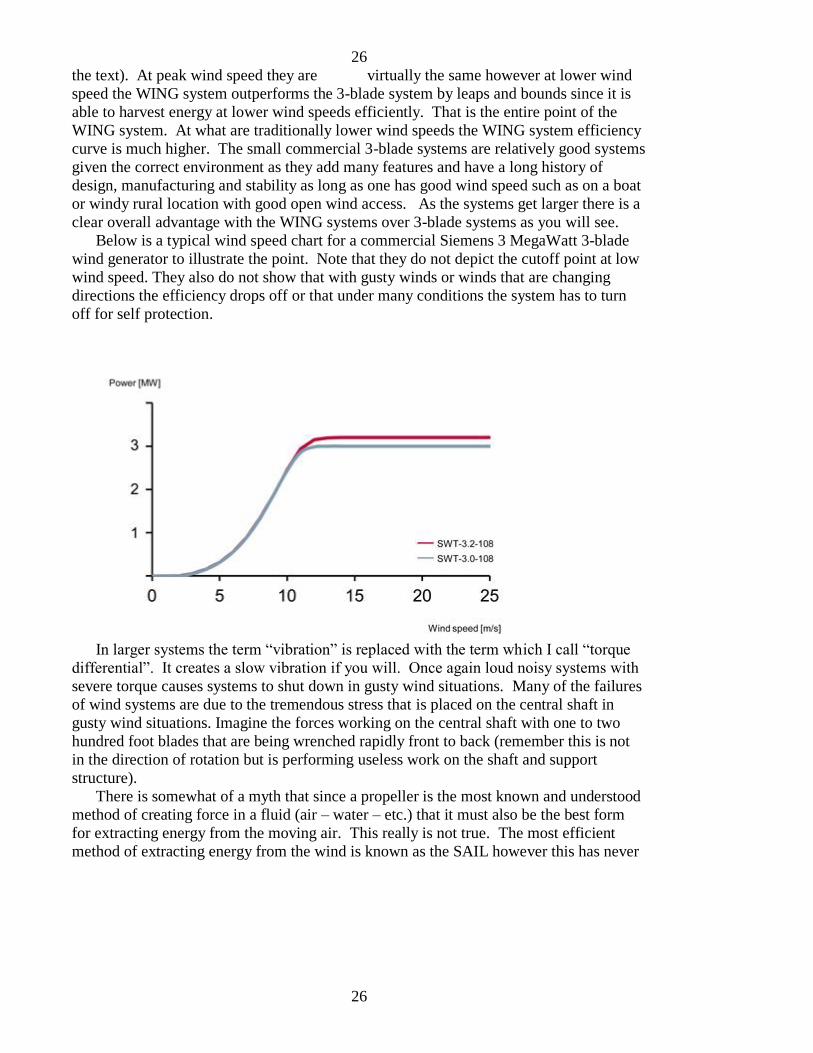
the text). At peak wind speed they are virtually the same however at lower wind
speed the WING system outperforms the 3-blade system by leaps and bounds since it is
able to harvest energy at lower wind speeds efficiently. That is the entire point of the
WING system. At what are traditionally lower wind speeds the WING system efficiency
curve is much higher. The small commercial 3-blade systems are relatively good systems
given the correct environment as they add many features and have a long history of
design, manufacturing and stability as long as one has good wind speed such as on a boat
or windy rural location with good open wind access. As the systems get larger there is a
clear overall advantage with the WING systems over 3-blade systems as you will see.
Below is a typical wind speed chart for a commercial Siemens 3 MegaWatt 3-blade
wind generator to illustrate the point. Note that they do not depict the cutoff point at low
wind speed. They also do not show that with gusty winds or winds that are changing
directions the efficiency drops off or that under many conditions the system has to turn
off for self protection.
In larger systems the term “vibration” is replaced with the term which I call “torque
differential”. It creates a slow vibration if you will. Once again loud noisy systems with
severe torque causes systems to shut down in gusty wind situations. Many of the failures
of wind systems are due to the tremendous stress that is placed on the central shaft in
gusty wind situations. Imagine the forces working on the central shaft with one to two
hundred foot blades that are being wrenched rapidly front to back (remember this is not
in the direction of rotation but is performing useless work on the shaft and support
structure).
There is somewhat of a myth that since a propeller is the most known and understood
method of creating force in a fluid (air – water – etc.) that it must also be the best form
for extracting energy from the moving air. This really is not true. The most efficient
method of extracting energy from the wind is known as the SAIL however this has never
27
27
been adopted to modern wind generation systems mainly because I believe the
connection to the Holland style wind mills with their slow lumbering blades are not seen
as sources of efficient power. You will see also why these age old designs are good but
could have been greatly improved long ago but this never happened. Once again when a
design is accepted the norm is to maintain without further investigation.
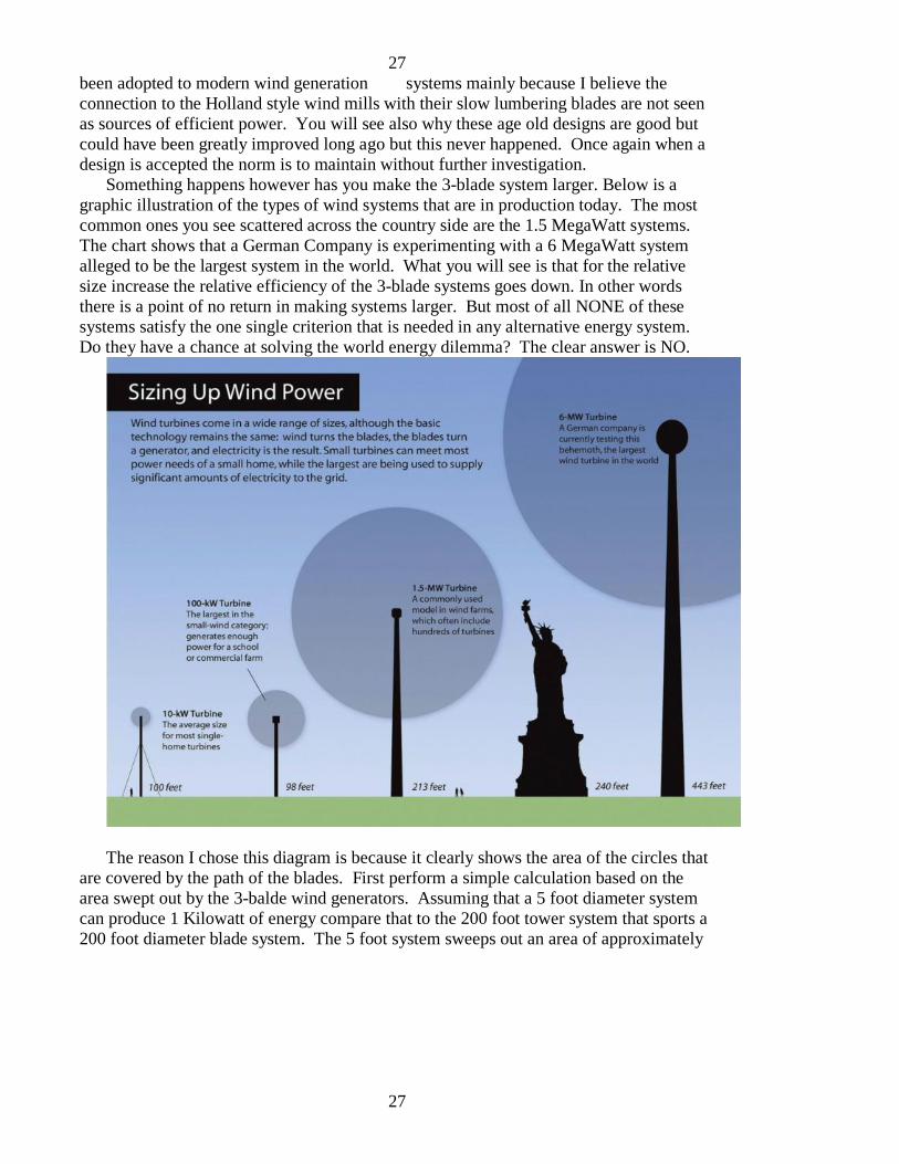
Something happens however has you make the 3-blade system larger. Below is a
graphic illustration of the types of wind systems that are in production today. The most
common ones you see scattered across the country side are the 1.5 MegaWatt systems.
The chart shows that a German Company is experimenting with a 6 MegaWatt system
alleged to be the largest system in the world. What you will see is that for the relative
size increase the relative efficiency of the 3-blade systems goes down. In other words
there is a point of no return in making systems larger. But most of all NONE of these
systems satisfy the one single criterion that is needed in any alternative energy system.
Do they have a chance at solving the world energy dilemma? The clear answer is NO.
The reason I chose this diagram is because it clearly shows the area of the circles that
are covered by the path of the blades. First perform a simple calculation based on the
area swept out by the 3-balde wind generators. Assuming that a 5 foot diameter system
can produce 1 Kilowatt of energy compare that to the 200 foot tower system that sports a
200 foot diameter blade system. The 5 foot system sweeps out an area of approximately
28
28
20 square feet whereas the 200 foot diameter system sweeps out an area of
approximately 31,500 square feet and produces a stated maximum output of 1.5
Megawatts. This comparison shows that the maximum quoted efficiency is directly
proportional to size. The ratio of the areas swept out by the blade system (the cross
section of wind) is about 1500 and the stated output of the systems is about 1500 also. If
one looks however at the measured output curves of both systems, even with the
feathered blade capability of the larger systems, the efficiency vs. wind speed of the
larger systems is far below that of the smaller systems. You will never get anyone in the
industry tell you this. The larger systems are also wrought with mechanical problems and
complexities. Many set idle waiting backlogged parts as it is always the same parts that
fail. In their rush to market to gain a competitive edge some engineering was slighted.
So the backlog and company warranty support cannot keep up with the demand of failed
systems.
This brings to mind a letter I received from a listener of my weekly radio show
responding to comments I had made regarding the 3-blade systems. Her school in a rural
area decided to “go green” and purchase a wind tower. The kids sold things to raise the
money and the community was abuzz about the new effort. At long last they had the
money and selected a company to install their wind system on a hill overlooking the
school. The trucks came and the small farming community beamed with pride as the
huge pieces were assembled. The future of free energy and a community project coming
to completion kept them feeling content.
The project was completed and at long last the big blades began to turn and produce
electricity. The first thing they noticed was the noise emanating from the huge system
that kept them from sleeping at night. Since it was on the highest hill in the area the
noise ranged far and wide. But the still could remain content knowing that their school
project and hard labors were paying back in free electricity.
Then one day there was a loud noise and the big blades started to make a noise that
did not sound good. There was something broken inside and the called the maintenance
company. They responded and said there were certain parts that had to be ordered and
replaced but that there was a backlog on these parts. Weeks went by and their calls were
met with answering machines and no response. The big system had been shut down so it
did not make any noise anymore and likewise was not making any electricity. When the
listener wrote to me it had been over a year and the town including the kids who had
worked hard selling their goods to buy the system. The listener could go to the tower and
could point to the parts that were dysfunctional. To this day the hill top monster stands as
a tribute to an industry that has failed the public and walked away with the profits.
Entire countries now stand with economic egg all over their collective faces and
“wind alternative energy” has gained a bad name. Was this the intention all along? Was
this an industry that was designed for failure or is it an industry with a history of
incompetence and engineering failures where no one really examined what they were
doing? It certainly has a healthy dose of the second.
Now imagine the 3 thin blades setting there on a relatively average wind day barely
spinning. Literally all the wind is blowing right through the wind generator without
29
29
being captured and without doing a single ounce of useful power generation. Even at
max RPM the systems cannot respond to the engineering necessity of one blade
following the other as they rotate.
Let me explain this in detail. On a small 3-blade system rotating at 3600 RPM the
blades are “following” one another or “cutting the wind” right behind the cut of the next
leading blade. That is why small 3-blade (or small multi-blade) systems are relatively
efficient and can capture a good portion of the energy in the passing wind flow at 30
MPH wind speed (the truly good small systems use as many as 6 blades that are wider
and flatter but still follow the same concept that they must spin very fast to work). In a
30 MPH wind when properly designed each blade cuts the wind relative to the wind flow
just behind the wind flow cut of the adjacent leading blade. Thus the maximum amount
of energy can be extracted from the wind BUT REMEMBER that the vast majority of the
force generated does no useful work as the force vector of the airfoil is not directed in the
radial direction (it is directed towards the support shaft and performs no useful work apart
from causing a lot of noise and vibration). The small system has the ability to spin at the
required 3600 RPM and hang together although this is the source of many problems for
these systems when running at full RPMs.
On the larger system however, imagine the blades 100 feet long or larger spinning
fast enough to follow behind the next leading blade and efficiently cut the air behind the
next leading blade. Sorry Sponge Bob, it ain’t going to happen. In the larger systems the
vast majority of wind is passing through the 3 blades without doing anything relative to
useful work. They are SO INNEFFICIENT that it is amazing they are considered at all.
Relative to the small systems they simply cannot scale up to larger sizes and maintain the
efficiency. Essentially you cannot get large systems to spin fast. If they were designed to
spin at the 3600 RPM rate they would literally fly apart. We simply do not have
materials that would hold together under these stresses and furthermore one would need
the scaled up wind speed of 100 miles per hour. Clearly somewhere in the ivory towers
of the world engineering schools something was never noticed as the waves of engineers
were released who did not understand basic design principles (but all got their A’s and
got their degrees).
Small fast spinning systems DO NOT SCALE UP. When you see the design of the
WING systems you will start to understand the issues of design and scaling. I should
note here also that the majority of ALL wind generator designs likewise DO NOT
SCALE UP for many of the same reasons and therefore are of no value in solving the one
requirement of any alternative energy solution (to match the world physical energy
production economically). You will see that the WING GENERATOR designs become
MORE efficient as they are scaled up.
Let me take another example. In my youth I designed sail boats (the classic old
wooden kind) and learned some things about scaling of designs. In the case of sail boats
I was taking a design of a world famous cruising sailboat and making it smaller. The sail
plan goes as the square of the dimensions whereas the hull and its displacement go as the
cube of the dimensions. The result is that if you make a sail boat smaller you have to
reduce the amount of sail more than proportionately or the boat will not be able to handle
30
30
the sail plan in normal wind conditions. Conversely if you make the boat larger the
hull does not have to be as wide or displace as much water to handle a larger sail plan.
This is called “scaling” and any design must be adjusted according to sound
engineering principles. In brief, the 3-blade wind generators DO NOT SCALE UP.
When we start to compare the WING GENERATOR with the 3-blade systems you will
understand more about all the defects of scaling related to the 3-blade design.
The larger 3-blade systems are so inefficient at low wind speeds that they need a
motor to get them rotating. Imagine that, a wind generator that needs a motor to start but
it is true. This leads to another difficulty of the 3 blade design. All of the heavy
equipment is hundreds of feet in the air in a housing that you wish to keep as small as
possible to reduce wind problems. But the issue of having all the hardware high in the
air creates a maintenance issue. Everything has to be taken up with large cranes or
elevators within the central shaft. You will see that with the WING design the heavy
equipment is at ground level and in the systems I have been experimenting the WING
systems are very light weight made from modern plastics and synthetic materials and
“stayed” with thin wire cables. The structures are extremely light weight yet strong.
In conclusion the 3-blade systems are extremely inefficient at average wind speeds
and do not scale up to large sizes. As they become larger they develop many problems
related to simply being large and last but not least they do not satisfy the single important
criteria necessary for any alternative energy solution. They will never solve the world
energy problem no matter how many are installed. The pay back on resources invested is
simply not there as they have painfully learned in England and the Netherlands.
The only manner in which these wind generation companies can survive is through
government subsidies and benefits whether it is directly to the company or through the
back door via tax incentives to customers who buy “alternative energy”. If you look at
the large installations that now lay idle around the world (and which are never mentioned
in the glossy trade magazines of the wind alternative energy industry) they ALL had
government subsidies. The systems that are in existence are quoted by their companies
using the maximum “installed base” of output but they never tell you that the real output
is at best 10% when you include maintenance. If you subtract out the government
incentives these systems could never be cost justified by any sane corporation. Clearly
someone with interest in maintaining this façade for the public is behind it and you the
public once again are paying for it.
Remember the race to install bio-fuel installations from corn. All of a sudden the
farms were competing with oil prices. This once again met with heavy government
subsidies and was highly successful until they had to maintain on their own. At this point
the true inefficiencies of the process came to light … something that was hidden in any
cost analysis as this bill of goods was pawned off on the unsuspecting public who
cheered it all the way to its final day of destiny. This all ended in a giant fiasco however
many investors made out big time including the companies that installed the facilities to
the investors who gained immediate profits based on government kick back incentives
and the vendors. Another silent victim were the masses of people around the world who
starved to death because the replacement of corn in the fuel market drove up world grain

31
31
prices and the marginally poor simply could not afford to eat. No one that made
off with the goods (ill gotten gains) ever batted an eye lash. I knew many of these people
as I worked behind the scenes around the year 2005 to implement my WING systems
only to have to compete with this monetary sham.
After you understand the engineering issues you will start to become suspect of the
intentions of large scale corporations like General Electric and Siemens investing in a
technology (commercial 3-blade wind generators) that takes valuable alternative energy
resources and investment money and which will never replace the major electrical energy
systems that they also build such as nuclear power plants.
You will also become suspect of efforts for example by current President Obama to
race continue tax incentives to “alternative energy” that will never make a difference but
which indirectly supports and industry with very expensive “solutions” or to distribute
water rights to companies to place offshore wind generation facilities that will later
prevent anyone else from putting in installations that could in fact make a difference in
the world energy crisis. His plan to shut down coal burning electrical generation plants is
nothing more than a way to create a monopoly with nuclear power in the USA and force
electric prices sky high at a time when we desperately need true alternative energy
solutions. Shutting down coal plants to force more dependence on nuclear power
generation is not a solution for future generations (“for the children” as the forked
tongued Obama claims).
I have another story related to the wind generation business and it appears that some
major corporations are positioning themselves in the small home alternative wind energy
market. I recently saw an advertisement coming from a electronics firm that makes all
kinds of electronics for home and business offer a roof top wind generator with some
amazing claims. Upon further examination I noticed some strange specifications. The
system is rated at “2 KW” or 2 kilowatts. They note that this is at a maximum wind
speed of 45 miles per hour and is being sold through a national home improvement chain.
The cost is under $5000.00 at this time complete with electrical controller. The problem
I have with this is that how often are you going to have a 45 mile per hour wind at your
house and in the city you will have other issues such as trees and neighborhood
structures, etc. With a commonly seen efficiency curve of systems like this one would
expect that at normal everyday wind speeds one would be lucky to obtain a few hundred
watts at best. I believe we are going to see more marketing ploys like this to sell a bill of
goods to the public just like the manufacturers of automobiles use false mileage data on
hybrid cars to sell a product (not quoting that the super gas mileage is coming at the
expense of nuclear and coal fired electricity).
“RESISTANCE” is forming around the globe against wind systems being carte
blanche approved by governments with big business in their back pockets putting tax
payer money into the wind businesses that produce no final product (energy). One such
resistance movement is in Ontario Canada where they are very well organized and on to
the games that industry plays with governments. The following letters to a government
official posted on their web page shows the attitude.
32
32
Letter posted on the web page (citizen to politician) Ontario-wind-resistance.org
Mr. McGuinty:
The Green Energy Bill 150 is the tip of the iceberg in your web of deceit and lies. Never
again will I trust your Government. We, the people have been lied to, ignored, and our
lives and homes have been devalued.
CanWea has infiltrated Government at the highest levels. Their members, Mr.
Livingstone, Mr. Howe, Helimax, Stantec and Aercoustics spin their web to confuse the
general public. But the truth is beginning to emerge despite their money, deceit and lies.
With profits of $500,000. per turbine per year and government incentive money , from
our hard earned tax dollars, to line their pockets, CanWea is like a cancer that won’t go
away.
The truth is now out in the open. The wind turbines are noisy, a health and safety hazard
to birds, bats, man and animals, a visual blight to rural landscapes, and all the time doing
nothing for the carbon footprint or the power needs of future generations.
Mr. McGuinty lets put a turbine 350 meters from your back door and one in your child’s
school playground. Only then can you truly understand the meaning of
NIMBY…..sleepless nights, fear, dodging flying ice and devaluation of your home……
Add my name to the mass opposition to Bill 150-The Green Energy Bill, that is anything
but Green. I think that Red is a more appropriate color for this bill….The Red Energy
Act….Symbolizing people’s anger, and death of a lifestyle we will never again have as
you industrialize our rural landscapes, and turn your back to our objections.
With disgust
Joan Lever
A second letter also posted on Ontario-wind-resistance.org
Re: McGuinty advice to Federal Parliament
On December 10, 2007 Premier McGuinty made the following statement directed at the
Canadian Federal Parliament.
“…it’s about every Canadian having a fair voice in the debates that affect each and every
one of us.”
Apparently this statement does not apply to the McGuinty Liberals.
What does Premier McGuinty do when Ontario residents express their voice regarding
reported adverse health effects from wind turbine complex exposure? The answer is
Premier McGuinty labels these children, adults and seniors as NIMBYs.
What does Premier McGuinty do when 19 Ontario municipalities express their voice by
passing resolutions requesting that the McGuinty Liberals study issues such as health
risks associated with wind turbine complex development? The answer is Premier
McGuinty ignores them and introduces the Green Energy Act.
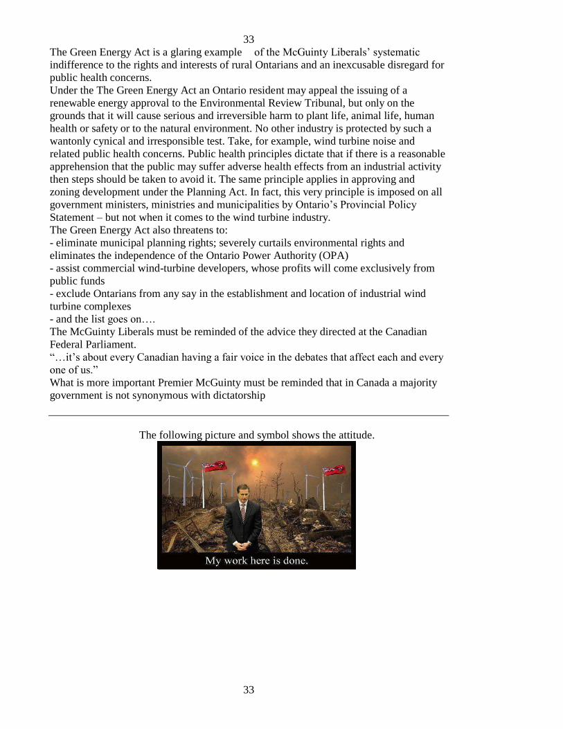
33
33
The Green Energy Act is a glaring example of the McGuinty Liberals’ systematic
indifference to the rights and interests of rural Ontarians and an inexcusable disregard for
public health concerns.
Under the The Green Energy Act an Ontario resident may appeal the issuing of a
renewable energy approval to the Environmental Review Tribunal, but only on the
grounds that it will cause serious and irreversible harm to plant life, animal life, human
health or safety or to the natural environment. No other industry is protected by such a
wantonly cynical and irresponsible test. Take, for example, wind turbine noise and
related public health concerns. Public health principles dictate that if there is a reasonable
apprehension that the public may suffer adverse health effects from an industrial activity
then steps should be taken to avoid it. The same principle applies in approving and
zoning development under the Planning Act. In fact, this very principle is imposed on all
government ministers, ministries and municipalities by Ontario’s Provincial Policy
Statement – but not when it comes to the wind turbine industry.
The Green Energy Act also threatens to:
- eliminate municipal planning rights; severely curtails environmental rights and
eliminates the independence of the Ontario Power Authority (OPA)
- assist commercial wind-turbine developers, whose profits will come exclusively from
public funds
- exclude Ontarians from any say in the establishment and location of industrial wind
turbine complexes
- and the list goes on….
The McGuinty Liberals must be reminded of the advice they directed at the Canadian
Federal Parliament.
“…it’s about every Canadian having a fair voice in the debates that affect each and every
one of us.”
What is more important Premier McGuinty must be reminded that in Canada a majority
government is not synonymous with dictatorship
The following picture and symbol shows the attitude.
34
34
This symbol shows the attitude of the public in Canada where they now realize that
they have subsidized and industry that has taken the money and run. Never in the
contracts was there a line about who should remove these useless 3-blade monstrosities
when they failed to perform. Any good contract would have a failure to perform clause
but NONE of these ever did. It was all about the government dumping public money
directly into the pockets of industry through “incentives” at the rate of a half million
dollars per year per tower. This has happened in the USA as well and in many countries
around the world. For more information see sites such as http://www.na-paw.org/ .
Look at the deceptive names given to the Canadian directives “Green Energy and
Economy Act of Ontario”. Need I say more? You see this consistently with politicians
who create names that are covers for the real actions which generally rob from the
unsuspecting public and sell on motifs that fool the public long enough to get the
legislation passed and then it is too late. The money is spent … the liars and thieves have
absconded and run with the money and the only thing left in their dust are the angry faces
of the people holding signs in protest. I am not sure why there are not more lynching
sessions or at least tar and featherings as in the old western movies where the snake oil
salesman and his sidekick are running out of town for their lives.
Do you think this blocks the advancement of REAL alternative energy? YES because
now all the money has been spent on a pig in a poke as the old expression goes. There is
no money left let alone public interest to entertain real alternative energy. Could this
have been the plan all along (to crush alternative energy from ever seeing the light of day
by following a dead end path) or was this a case of bad NASA engineering from the start
(where this whole 3-blade fiasco began) and everyone followed the lead sheep over the
cliff? It really is a mute point right now as the world has gained a severe bad taste for
alternative energy.
This ushers in a future of dependence on nuclear – coal – big oil for the autos – and
the bogus “hybrid” automobiles who gain their power from horribly inefficient nuclear
and coal electricity. Even in this vein the major automobile industries have dragged their
feet and the best thing they can do is try to prevent real electric cars like the TESLA from
being sold in their respective states. Clearly there is a marriage of reliance between big
auto and big oil and this is not going to end any time soon.
The world of large international corporations and politics and all that goes with the
energy issues is complex. Real solutions are necessary but you will never see these come
from the companies entrenched in maintaining the current status quo.

35
35
The following is a photo that depicts just one of the failed wind projects stationed on
the windswept island of Hawaii. The reason I am showing this here is because these
3-blade wind generators have been idle almost since their installation decades ago. The
earth will be scarred with this blight unless the people are allowed to dismantle them and
make them into furniture or electric car parts of something of earthly use.
.
36
36
VI. The McCanney WING GENERATORTM
With the basis of understanding the flaws of the current industry standard commercial
3-blade wind generators detailed in the previous chapter you will be able to understand
the reasoning behind the WING GENERATOR.
There is a story about Christopher Columbus as he met with the Queen looking for
funding for his venture to find a route to India by sailing west. Remember at this point in
history all the nobility knew that the world was round. It was just the bad science that
they pawned off on the public to make them think the world was flat that was meant to
keep the public at bay and mentally sequestered.
At any rate the story goes like this. At a party of dignitaries someone proposed a
challenge to anyone who could balance an egg on one end. The people in turn attempted
and tried but all failed to maintain the egg on end for more than a split second. Columbus
however took the egg (which he knew was hard boiled) and gave it a slight tap flattening
it on one end. With this he sat the egg on end and won the favor of the queen for his
insight that had escaped all the others. The point is that once the obvious was seen it
became just that to all … obvious. But prior to that point no one could see the obvious.
The WING GENERATOR is something like the egg with Columbus. Once you see it
the obvious becomes just that. But first you have to understand the physics of moving
air. If you slow the air down in your efforts to remove energy from the air then you
create a back pressure that slows the wind down and diverts its path from your energy
extracting device. So you want to create as little back pressure as possible to keep the
natural air flow as linear as possible. Secondly and more importantly is the use of airfoil.
This of course is already used in the 3-blade systems however the extremely narrow
airfoil has its direction nearly perpendicular to the direction of rotation of a horizontal
axis turbine. One has to overcome the misconception that generators have to spin fast to
work. The reality is that the electric generator (that part of the system which turns
mechanical energy into electrical energy) which is comprised of moving wire in a
magnetic field … yes these have to move fast in fact the faster the better (the amount of
current generated is directly related to how fast the coils move through the magnetic
fields of the fixed magnets in the electrical generator design). The additional issue with
the airfoil is that the “lift force” is directly dependent on the base area so a larger airfoil
base will create a larger force. One wants this force to be greatest at the tips of the
airfoils because this is where the greatest torque is generated, but as mentioned in the 3-
blade design the tips are kept small because they are the main source of vibration as their
airfoils are directed towards (or away from) the tower.
For those not familiar with the physics terms for rotational dynamics “torque” is the
“cross product” (not just product to be explained in a second) of the force acting on the
“wheel” and the radius of action. If the force is not in the direction of rotation of the
“wheel” (or whatever round device you are trying to move) then only the component of
force that is helping move the wheel in the rotational direction is considered to be a
37
37
legitimate part of the torque. The radius factor says that the farther out you go from
the hub (center point of the wheel) the greater the effect of the force.
As an example the 3-blade wind generator moving at maximum rated RPMs may
develop considerable force BUT it is not directed in the direction of rotation so literally
almost all of the usable force is ill directed. The WING GENERATOR solves this
problem and as you will see has many other attributes that the 3-blade system cannot
accomplish. It is necessary to maximize these seemingly conflicting factors to create a
design that provides the greatest extraction of energy from the passing wind while
creating the maximum electrical power at the onboard generator transferring this to the
electric grid at the end of the process.
I suspect that the designs that will finally result from many upcoming years of
development will be a combination of improvements made by both individuals (including
myself as I continue my own research in this area) and possibly large companies.
Remember that one of my stated goals is to keep this out of the hands of the patent
hungry large corporations who wish to corner the market and make profit rather that
solve the world energy crisis with true alternative energy. That is why my open
architecture concept works against them since there will be no profit in their historically
greedy actions.
With this in mind I am now presenting the WING GENERATOR using a set of
engineering drawings that were produced in 2009 as part of one of my offshore ventures
that ended when the financial end of the team disappeared and I have never heard from
him again (that does not mean he is dead that only means I have been unable to locate
him).
SEE PATENT – TRADEMARK – OPEN ARCHITECTURE next chapter for
procuring usage rights for the WING GENERATOR
CRITERIA FOR ALTERNATIVE ENERGY TECHNOLOGY – there is one and only one criteria for any alternative energy “solution” – CAN IT REPLACE ON A WORLD
SCALE THE CURRENT HEAT CONVERSION ENERGY PRODUCTION SOURCES
AND DO IT ECONOMICALLY WITHOUT GOVERNMENT SUBSIDIES AND
CORPORATE CONTROL?
.
THE NEXT PAGES PRESENT THE WING GENERATOR
(be sure to view the chapter on the variety of configurations available for the WING
GENERATOR systems)

38
38
The first plate below shows the front – side – and isometric views of the 100 foot
prototype WING system as it was planned to be build on the deserted western beach in
Mexico. As you can see the base rotates to direct the wind perpendicular to the plane of
the wheel. To the average person this appears to look like the Farris wheel and in fact the
company that I was working with to do the design engineering is the builder of the
world’s largest Farris wheels (sometimes also called viewing towers). Part of the
engineering problem was to design a system that was scalable to 1000 feet tall and
withstand the stress of an operational wind system. One of the design parameters was
that the wheel would not spin fast (as is the requirement of 3-blade wind systems). Also
remember that in the WING system the airfoils which are very large are pushing
(directing their force) in the rotary direction which minimizes the lateral forces. The
relative cross section blocking the wind flow is minimal and therefore the forces are not
trying to blow the system over so to speak. The view on the left below (front view)
illustrates this point.
In place of the x panels you must envision the “WING” cross sections. In my own
designs I use extremely light weight plastic and synthetic materials in the form of sails
rather than wings that can be furled and adjusted based on wind conditions. They create
less stress and are less demanding on the base structure.
One of the design parameters is the width of the sails or wings. As the surface area of
the wings increases, the useful force also increases. So this design by its very nature is 3
dimensional whereas the 3-blade generators only increase in 2 dimensions.

39
39
The second plate below illustrates the prototype system on a deserted beach to
scale. You can see the 50 foot tall palm trees and a person next to this structure. Now
imagine assembling the pieces. One of the beauties of the WING system is that ALL of
the construction takes place from the staging platform (where the belt driven generator is
currently positioned). You begin by erecting the support structure and after that the
entire assembly is put together piece by piece and then rotated so the next piece is
assembled from the staging region. At last the heavy equipment is placed on the staging
area. The smallest to largest systems will have all have the heavy equipment on the
ground level where maintenance is readily available. If changes to the WING or
structure need to be made they are done from the staging area. You do not need huge
cranes to move heavy equipment to heights and then send technicians up to make repairs
or regular maintenance. The advantage of a belt driven system is that the new Kevlar
belts have nearly an infinite life time in all weather conditions. They offer a simple
inexpensive method of altering the slow turning highly efficient WING wheel to the
GENERATOR portion allowing for up to 3600:1 ratios where the larger wheels might
make one revolution per minute yet the generator would be turning at the 3600 RPM
industry standard rate. Also as with for example Hydro Electric systems, multiple
generators motors can be staged and brought online depending on the wind speed and
user demand. SIMPLE – EASILY ASSEMBLED AND MAINTAINED – WORKS
WITH LOW WIND SPEED ANDIS SELF STARTING – the extensive list of advantages
will be presented below. Since all of the WINGS are connected structurally, the WINGs
all perform work to their abilities and self adjust for wind speed and direction.

40
40
The third table is a scaling representation for future expansion. These planned
systems would take us from the 100 foot prototype (at left) to the full size 1000 foot
diameter WING GENERATOR capable of power generation from 200 to 500 Megawatts.
I have made estimates that the peak output of a well designed 1000 system could be as
high as 2 Gigawatts based on the expansion of the WINGs in the Z direction. In the
model diagram below the width of the WING slots are 75 feet. This dimension can be
tripled to 200 feet and additionally the number of veins or WINGs inserted in the gaps of
the large system can be greatly increased. This traps a larger cross section of the wind
and as noted in the design parameters the object is to extract the maximum amount of
wind energy without disturbing the wind flow. An additional effort can be made by
adding a secondary set of WINGs behind the first set using the same principle as geese in
flight where the lift of the lead goose provides flight advantage for the second goose
which does the same for the third goose. This is why they fly in V formations. Thus the
WING design expands in 3 dimensions providing much more ability to extract energy
from the passing wind. Note the belt drives in the diagrams illustrate a 1:1 ratio however
real systems can change this by as much as 3600:1 or more OR use efficient gear
reduction transmissions to change the slow wheel rotation rates to generator speeds. A
good deal of engineering has already been done on the feasibility of the large systems.
The next pages illustrate the work performed by the engineering companies like USI-
SYSTEMS noted in the drawings below.
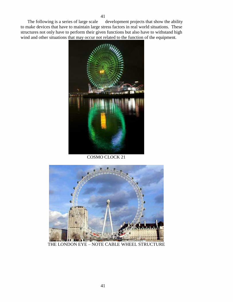
41
41
The following is a series of large scale development projects that show the ability
to make devices that have to maintain large stress factors in real world situations. These
structures not only have to perform their given functions but also have to withstand high
wind and other situations that may occur not related to the function of the equipment.
COSMO CLOCK 21
THE LONDON EYE – NOTE CABLE WHEEL STRUCTURE

42
42
NAVY PIER CHICAGO
RIESENRAD
43
43
TOURIST PHOTO
SINGAPORE FLYER
44
44
TEXAS WHEEL
THUNDER DOLPHIN BIG O

45
45
TOKYO EYE
These structures are for tourist fun and to strike awe in the eye of the beholder. These
same design principles can be used to harness the power of the wind and drive our entire
energy needs worldwide. Oddly enough the diesel powered boat in this picture could
easily be driven directly by WING systems on the roof and assisted by electric motors
that derive their energy from the large scale WING GENERATOR systems when at dock
for the night. In fact well designed boats and automobiles with fair lines and wind entry
offer little resistance. Is it not odd in our world of auto and truck engineering that all
seem to have large flat rear panels that act as a vacuum drag that is constantly pulling the
vehicles backwards causing further excessive use of gasoline and fuel. Do you think that
the engineers are so stupid that they never have figured this out? These are on the
“economy” cars. The other option is a gas guzzling SUV that has worse gas mileage than
a 1950 giant Cadillac. Are there design constraints to make these “fossil fuel monsters”
as gas inefficient as possible?
Electric autos and mass transit vehicles for local transportation should all be operating
on electric and this electric should not come from burning high energy content fuels such
as coal or nuclear (or #2 fuel oil or natural gas). In a real world with real energy
solutions these should have been outlawed long ago. Wind power is the only rational
alternative energy. Solar power cannot match it for consistency in all parts of the world
at all times of year. Hydro and other less used forms of alternative energy are extremely
expensive to implement. The construction of only 300 of the large 1000 foot WING
46
46
GENERATOR towers in high wind areas of the United States would provide us with
eternal free energy for the cost of maintenance. By contrast it would take over 77 million
of the 1.5 megawatt 3-blade generators. We can convert to wind and transport the energy
from wind areas to the rest of the country on the currently existing power grid (NO
SMART GRID NEEDED).
The cost of construction of the WING GENERATOR towers would be less than a
few nuclear reactors and the social and economic benefits would be passed on
immediately. Conversion to a truly electric transportation system with free electric non-
polluting power should have obvious benefits. Clearly this will not exactly be popular in
certain circles.
WING GENERATOR CONFIGURATIONS
As you will see the WING GENERATOR concept is very adaptable from small direct
drive systems and home electric generation to full scale commercial direct drive or
electric generation systems. Rather than drawings I will simply describe the
configurations starting from the smallest to the largest and let your imaginations carry
you into the future.
There is a great need in the small home wind generator industry for a small
conversion from the inefficient 3-blade wind generator designs to WING designs.
Unfortunately this is not the optimal design platform for the WING designs but what are
you going to do with all the hardware already installed around the world. I have adapted
some of the small commercial 3-blade wind generators to WING configurations using off
the shelf gear reduction housings and the results are limited due to the gear reduction
itself. There are two possibilities in the conversion. Leave the 3-blade housing and adapt
a WING system to the housing with gear reduction OR reconstruct the housing and
control electronics to simply be the alternator on the WING system. In general the
alternators and support electronics for the commercial 3 (or multi) blade systems are
excellent and offer many benefits that will save the batteries and protect against high
wind situations. Their drawback is in the 3-blade system itself.
Direct drive applications like wind support water pumps. The history of wind is well
rooted in the old farm wind mill. It is an interesting design with a self starting blade
system that begins at nearly zero wind speed. It gains its power by redirecting the wind
with flat or slightly curved blades and is the old reliable made of durable light weight
metals. After 100 years some are still standing and working. The issue with these is that
they never took advantage of the wind with air foils. An airfoil affords a 10 times
advantage over a flat or slightly curved plate that simply diverts the air. Once again over
100 years of wind design developers seemed to miss the idea that capturing energy from
the wind is different from using a propeller to drive the wind, thus wind energy designs
have always been made on the basis of propellers running in reverse. They work but not
at the efficiency necessary to truly trap energy from the wind. Likewise the 3-blade wind
generator propeller like designs use an airfoil but the resulting force from the thin blades is mostly directed in the direction of the tower that supports it, not in the direction of
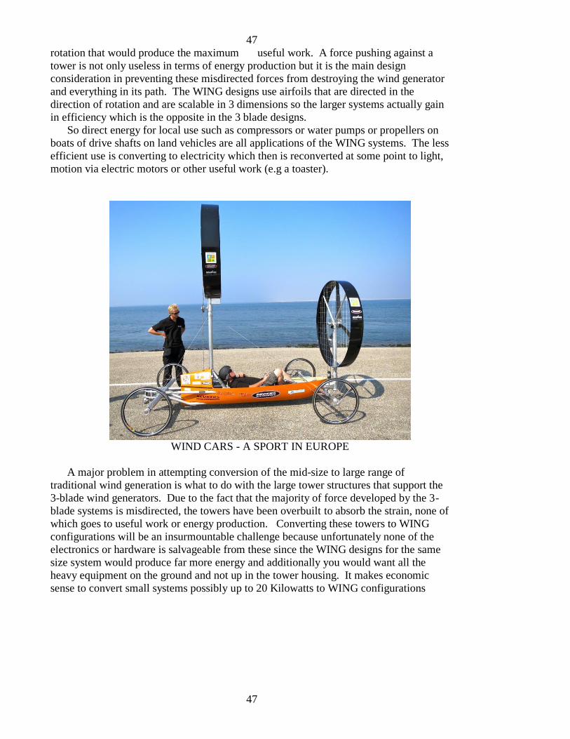
47
47
rotation that would produce the maximum useful work. A force pushing against a
tower is not only useless in terms of energy production but it is the main design
consideration in preventing these misdirected forces from destroying the wind generator
and everything in its path. The WING designs use airfoils that are directed in the
direction of rotation and are scalable in 3 dimensions so the larger systems actually gain
in efficiency which is the opposite in the 3 blade designs.
So direct energy for local use such as compressors or water pumps or propellers on
boats of drive shafts on land vehicles are all applications of the WING systems. The less
efficient use is converting to electricity which then is reconverted at some point to light,
motion via electric motors or other useful work (e.g a toaster).
WIND CARS - A SPORT IN EUROPE
A major problem in attempting conversion of the mid-size to large range of
traditional wind generation is what to do with the large tower structures that support the
3-blade wind generators. Due to the fact that the majority of force developed by the 3-
blade systems is misdirected, the towers have been overbuilt to absorb the strain, none of
which goes to useful work or energy production. Converting these towers to WING
configurations will be an insurmountable challenge because unfortunately none of the
electronics or hardware is salvageable from these since the WING designs for the same
size system would produce far more energy and additionally you would want all the
heavy equipment on the ground and not up in the tower housing. It makes economic
sense to convert small systems possibly up to 20 Kilowatts to WING configurations

48
48
(simply to benefit from the electronics) but for power levels above that there is no
economic rational to convert what is standing in the field. These eye sores will someday
be sold for scrap metal to remove their rusting hulks as a blight on the countryside.
The WING systems best location is out on the open planes on elevated platforms or
on a roof top with access to good wind free of trees and hills nearby. The larger systems
should be placed on the open planes or on open water on a barge. The following picture
is taken from my 110 High Altitude Photos of the American Southwest that I sell on my
web page. It depicts a region of the American southwest just one (of which there are
many remote areas) with constant straight line winds capable of producing large
quantities of energy for the National WING project.
POTENTIAL LOCATION FOR A REMOTE WING SYSTEM
e

49
49
TABLE OF COMPARISON BETWEEN THE 3-BLADE AND WING SYSTEMS
CRITERIA
Installation
Maintenance
Eco-friendly
Can it solve the world
energy crisis ?
3-BLADE SYSTEM
Requires large cranes – lift
heavy equipment to top of
tower
Requires internal elevators
or cranes for even the most
minor repairs
Are noisy and kill birds –
low frequency vibration
noise carries for miles
across the countryside – are
unsightly standing
motionless against the
horizon
NO – it would take 77
million 1.5 megawatt 3-
blade towers (operating at
the industry average of 15%
with all operational
24/7/365) to come close to
replacing world energy
needs
WING GENERATORTM
Installs from the ground
level without the use of
cranes – all heavy
equipment is at ground level
All maintenance is
performed from the staging
platform or on the ground –
light weight construction
allows even medium sized
installations to be
assembled by hand
Slow speed and white sails
make this an eco friendly
design which does not
damage wildlife – large
systems are quiet and
vibration free – are pleasing
to look at – the large scale
systems produce enough
energy to solve the world
energy crisis and would be
placed in remote regions
and offshore
YES – with just 300 of the
1000 foot towers we could
shut down all coal – nuclear
– and other heat conversion
electric generators in the
USA and would allow third
world countries to develop
without dependency on
world politics of oil and
nuclear power

50
50
Aesthetically pleasing
Low wind conditions
Mid wind speeds
NO – the country side is
littered with thousands of 3-
blade wind generators
which do not contribute
significant energy
Need an assist motor to start
them even in moderate wind
conditions – they require a
good deal of energy and are
horribly inefficient at low to
mid wind speeds
Even a few MPH less wind
than their maximum rating
can drop to 50% of peak
rated power output – their
efficiency curves make
them essentially useless at
mid wind speeds as most of
the wind blows through the
3-blades without creating
any useful work – the
blades airfoil force is
directed mainly
perpendicular to the
rotational direction of the
hub and do not contribute
any useful work – this also
causes the blades to work
against one another causing
vibrational modes that
require extensive
engineering and is the cause
the systems to shut down on
gusty days or to fail
prematurely
YES - A few major
installations in out of sight
locations will provide us
with all our energy needs
Self start at near zero wind
speeds and have a high
efficiency even at low wind
speeds
At mid wind speeds the
WING systems are highly
efficient which is a result of
the fact that the sails or
wings are driving the wheel
in the direction of rotation –
their ability to capture wind
energy is augmented by the
fact that they are 3
dimensional with large
surface areas – the sails or
wings are integrated into a
single wheel so that no
matter what the angle of
attack or strength of the
wind all WINGs contribute
to the overall rotational
torque to the ability – their
airfoils which provide up to
10 times the force of a flat
blade are directing that
force in the direction of
rotation – they never work
against one another – the
WINGS can be designed to
self adjust to local wind
speed and direction (with a
simple trailing edge
feathering trailing edge) so
each WING is optimized for maximum torque

51
51
High wind speeds
Overall weight
Offshore installation and
maintenance comparison
Scalability
Generally the 3 blade
systems shut down in gusty
or high wind speed
conditions – only in steady
mild conditions do they
work without down time
Heavy components are
required because of the
stress put on the system –
heavy equipment is
hundreds of feet in the air
Towers require massive
cement footings underwater
that support a single tower –
they require helicopters and
massive sea born crane
systems for installations and
maintenance - maximum
practical size of these
generators is currently 3
Megawatts – the only way
these systems can be
profitable is with
government subsidies – due
to inefficient design they
generally only produce
about 15% of peak power
when operational
The 3-blade system is a 2
dimensional design that
requires high RPM in the
blade system and therefore
do not scale up to larger
dimensions – the largest
systems to date 1.5 megawatts and a few 3
contribution no matter how
gusty or variable the wind
Self furling self directing
independent sails used as
wings can work under the
most stringent gusty
conditions and still produce
useful power
Components are super light
weight strong made from
synthetics – cable “wheel”
systems with ultra-light sail
material – heavy equipment
is at ground level
Off shore installations are
placed on floating barges
which can be assembled or
repaired at a dock and
moved to offshore locations
– the only underwater
equipment is a chain and
anchor – they adjust to
changing wind directions by
swinging on anchor like a
sail boat at anchor - the
large 500 megawatt WING
systems can replace a single
large scale nuclear or coal
power plant – they can
convert our entire power
grid to free wind energy
The WING design is a low
RPM design that uses high
efficiency sails or WINGS
to extract energy from the
wind – it is a 3 dimensional
design and therefore
becomes more efficient with larger size as it grows

52
52
Voltage production at
source
Industry view
megawatt units are wrought
with engineering problems
with the estimated largest
possible size of only 6
megawatts (considered in
the industry to be a major
accomplishment)
The industry standard is 640
volts at the power head
which has to be converted
again to transport on the
high voltage transport
system
Although there is
tremendous hype in the
wind trade magazines the
reality is that many
companies and entire
countries have been
financially taken to the
cleaners by investing in the
3-blade wind generation
systems – power grid
operators currently view
wind and other sources of
“alternative” energy as a
thorn in their sides – the
current generation of
installed 3-blade wind
generator base do not
contribute significant
amount of energy and when
they come online the
operators have to constantly
adjust for their erratic
output
as the cube of the
dimensions rather than the
square (2 dimensions) –
larger sizes capture more
wind energy for their
overall size than the smaller
models – they therefore
scale to extremely large
sizes capable of 500
megawatts or more
The remote large scale
WING GENERATORS will
be capable of producing
high voltage output directly
to the cross country power
transport system
TIME WILL TELL – but
with DISTRIBUTED
energy – direct power
applications of WING
systems that completely
bypass conversion to
electricity – large scale
WING systems distributed
around the country where
we will always have
electrical power generation
AND power storage in the
home – the new generation
of designs can fully replace
the coal nuclear and other
sources of heat conversion
power generation and lead
to an eco-friendly world
with electric ground
transportation and direct
drive WING generation
power for boats and ships

53
53
VII. PATENTS - TRADEMARKS – OPEN ARCHITECTURE
The reason for the higher than normal price for this book is because it is intended for
developers who will be interested in obtaining licensing rights. For those just interested
in another good read you must understand that this book is based on many years of
development and is more than a minor addition to resolving the world energy dilemma
and you are supporting this effort which has cost me personally a great deal of money,
time and other expenses over past years. This is in an industry where patents and
ownership of technologies are paramount; where it is becoming clear that the rights and
interests of the people take a back seat to corporate return on investment primarily based
on government subsidies. A trade magazine article is presented below to set the tone.
The wind generator trade magazines are filled with hype and delusionary vistas with the
image that landscapes covered with 3-blade wind generators as a thing of beauty. One
has to ask what on earth these people are smoking as the rage of public sentiment mounts
against GREEN and WIND and ALTERNATIVE government sanctioned projects.
To the contrary the people who are seeing this first hand and experiencing the
devastation caused while witnessing the lack of electric power output from the 3-blade
wind generators have become enraged with government subsidies. They hate GREEN.
They hate WIND. They hate ALTERNATIVE ENERGY. They hate two faced
government officials with slogans and political agendas like “Green Energy and
Economic Development”. But behind all of this is the ownership of technology and the
need of investors to reap a profit do not mind that the patents protect technologies that
simply do not work.
So with that in mind read the following article from a rah rah trade magazine and you
will pick up on the attitude that ignores the simple fact that the patents protect companies
whose products are a sham. Possibly they will someday have a taste of reality.
The following article is tell tale regarding the attitude of industry patent and
protection. Although it seems “pure and good” from a capitalistic western philosophy, it
clearly spanks of corporate greed and control. Remember that the ENTIRE reason for
patents was to afford the inventor temporary monetary compensation and keep others
from using the concept to the inventors benefit but also to produce incentives THAT
WOULD HELP MANKIND with technological advances. There should have also been a
clause that required the patent owner to use the patents towards those ends. Too many
times (especially in the energy industry) we have seen patents buried to protect the vested
interests of already existing technologies.
Read this article and I will use it as a stepping block to discuss my way of releasing
the WING GENERATOR technology to the public.
54
54
Article below is a news article used under open use policy from online www.windsystemsmag.com
Patenting the Winds of Innovation Companies are racing to protect their wind turbine technology with new patents,
helping protect the market positions of innovator companies and leading to
enhanced licensing opportunities.
Research and development activity at the world’s top wind-power companies has given rise to hundreds of new patents pertaining to all elements of wind turbine design, manufacture, and operation. Since 2001, the number of U.S. patents issued for innovations in wind power technology has continually increased (figure 1 omitted) . The 2011 projections are based on patents issued through September 30, 2011.
The last decade has seen the concentration of wind-power patents in a handful of top companies. Many companies recognize that a strong intellectual property position is important to protect their investments in research and development and to secure their market position. Patent leader General Electric entered the wind-power marketplace in 2002 when it acquired the assets of the Enron Wind Corp. and formed GE Wind Energy. GE has grown its wind patent portfolio rapidly since then, and it has been issued more wind-technology patents each year than any other company. Enercon, another market leader, benefits from a significant U.S. patent portfolio held by its founder and managing director, Aloys Wobben. Vestas Wind Systems began protecting its intellectual property in the U.S. in 2001, when it filed its first patent application. Vestas’ first U.S. patent was issued in 2003.
However, a significant portion of wind-technology patents are held by smaller players. They are made up of more than 100 individuals and companies including Acciona, Aerodyne Engineering, Clipper Windpower, DeWind, Gamesa, Northern Power Systems, and Valmont Industries.
Some companies have specific research focal points. For example, the ABB Group, headquartered in Switzerland, holds several patents for wind farm design, wind farm management, and operations methods for flexible and efficient energy delivery. Clipper Windpower, a Canadian turbine manufacturer, has patented several generator designs, as well as extendable/retractable rotor blades for wind and water turbines. Hitachi holds several patents on wind turbine generator designs. Dutch turbine maker NEG Micon, which was acquired by Vestas, focused research efforts on managing and dampening unwanted turbine blade oscillation, including using liquids within blade components to counteract blade stress.
55
55
Valmont Industries, headquartered in Nebraska, has focused on towers and structures and has several patents relating to methods for erecting a wind turbine rotor on top of a tower.
Patented innovations in the wind-power industry have focused on several key areas, including improved equipment design, especially for wind towers in remote locations; improved construction and assembly methods; and improved control and management techniques. With respect to equipment, inventors have continued to refine the basic components of the wind turbine and blades to improve efficiency, longevity, and safety. To compensate for the material degradation wind turbines face from their reliance on the elements, companies also have patented mechanical improvements and methods for reducing wear and damage from lightning, salt water, and ambient particulates that wear the turbine rotors. Turbine makers also have patented a number of strategies for managing the heat created by wind turbines, using air or water cycles to provide a renewable coolant. Several leading companies also have patented methods of noise dampening to make wind farms better neighbors and to overcome opposition to wind turbine installation.
A second key area, construction and assembly methods, has seen innovations directed to improving the ability to install wind farms in remote locations. Companies have patented a variety of methods for constructing turbine towers or pylons that reduce the use of cranes and heavy weights. They also have patented systems for remote monitoring of wind farms, including farms that take advantage of less accessible locations with favorable wind conditions.
Proper management and control has been a third focus. Because the wind does not always blow steadily, wind turbines must negotiate between variable blade rotation and the need of the commercial power grid for steady, fixed rates of electricity production. Inventors have addressed these problems, and the associated risks from power surges and abrupt cutoffs, with patented energy storage systems and techniques to balance turbine output within a wind farm. Recently issued patents describe improvements to reduce energy wasted in transfer to the electrical grid, and to maintain the economies of scale promoted by large rotor diameters. Monitoring systems also have been widely patented. A number of strategies have been developed to address and alert operators to the risks of wind sheer, imbalance of wind flow across a rotor, and material fatigue. There are several patented systems for alerting aircraft to the presence of wind turbines.
Patent Litigation As the installed base of wind energy increases and wind power becomes increasingly valuable, and as patent portfolios continue to grow, patent litigation
56
56
is likely to become more frequent. Enforcing their patents gives companies the opportunity to generate revenues based on their inventions, which can be re-invested to develop new technology, and to protect their exclusivity in the marketplace. A review of the litigation landscape indicates that a handful of wind-technology patents have been litigated thus far, and more could be on the way.
GE filed a complaint with the U.S. International Trade Commission (ITC) in 2008 seeking to bar Mitsubishi Heavy Industries (MHI) from importing wind turbines and components alleged to infringe three GE patents. The patents are generally directed to maintaining continuous turbine operation despite changing wind speeds and low voltage events, as well as to decoupling turbines from the grid to avoid damage from power fluctuations. In January 2010 the ITC ruled in favor of MHI. In re Certain Variable Speed Wind Turbines and Components Thereof, Investigation No. 337-TA-641. GE appealed the ITC decision to the U.S. Court of Appeals for the Federal Circuit. In a split decision, the Federal Circuit recently (1) affirmed that MHI’s wind turbines did not infringe one GE patent, (2) reversed the ITC’s ruling on a second patent and remanded the case to the ITC for further proceedings on that patent, and (3) found that the appeal was moot with respect to the third patent because it expired in February 2011. General Electric Co. v. ITC, No. 2010-1223 (Fed. Cir. Feb. 29, 2012).
The dispute between GE and MHI has resulted in further litigation in three federal district courts. First, before the ITC issued its decision, GE sued MHI in Texas for infringing the patents involved in the ITC investigation. General Electric Co. v. Mitsubishi Heavy Indus., Ltd., No. 2:09-cv-00229 (S.D. Tex., filed September 3, 2009). Shortly after filing, that case was stayed (and remains stayed) pending the outcome of the ITC investigation. Next, GE sued MHI in a different Texas court for infringing a new set of patents related to wind turbines. After a seven-day trial in that case, on March 8, 2012, the jury awarded over $170 million in damages to GE for MHI’s infringement of U.S. Patent No. 7,629,705, titled “Method and Apparatus for Operating Electrical Machines.” A separate trial on MHI’s inequitable conduct defense will be held later. General Electric Co. v. Mitsubishi Heavy Indus., Ltd., No. 3:2010-cv-00276 (N.D. Tex., filed Feb. 11, 2010). MHI countered with an antitrust lawsuit asserting that GE fraudulently obtained patents and pursued “sham “ litigation. Mitsubishi Heavy Indus., Ltd. v. General Electric Co., No. 5:10-cv-05087 (W.D. Ark., filed May 20, 2010). The antitrust case is on hold pending the outcome of the patent cases. GE also sued an inventor—a former GE employee—over rights to certain patented technology, and MHI intervened in that lawsuit. General Electric Co. v. Wilkins, No. 1:10-cv-00674 (E.D. Cal., filed Apr. 15, 2010).
In an earlier lawsuit, Gamesa Eolica, S.A. v. General Electric Co., 359 F. Supp. 2d

57
57
790 (W.D. Wisc. 2005), Gamesa sued GE in 2004 for infringement of a patent related to a variable speed wind turbine with a special control strategy based on electrical adjustment of generator torque. The parties disputed the scope and interpretation of the patent claims, and the court sided with defendant GE. Ultimately, GE was cleared of any direct infringement.
GE is not the only litigant in the wind energy space. One of the same patents at issue in the GE-MHI dispute was litigated 10 years earlier, in Enercon GmbH v. ITC, 151 F.3d 1376 (Fed. Cir. 1998). The Federal Circuit upheld an ITC ruling that Enercon had sold infringing variable speed wind turbines for importation into the U.S. The key issue on appeal was claim interpretation. Enercon, the accused infringer, lost the appeal and was barred from shipping some of its turbine designs into the U.S.
In Baseload Energy, Inc. v. Roberts, No. 1:08-cv-01838 (D.D.C., filed Oct. 27, 2008), Baseload sought a declaratory judgment that Robert’s patent, directed to kite-based power generation, was invalid. The case has progressed slowly since the Federal Circuit ruled in September 2010 that Baseload’s claims were not barred by an earlier settlement. Finally, Vestas sued Beaird over three patents relating to wind-turbine support towers, seeking a judgment that it did not infringe. Vestas-American Wind Technology, Inc. v. Beaird Company, Ltd. et al., No. 3:07-cv-01651 (D. Or., filed Nov. 2, 2007). The case settled in March 2009.
Strategic Enforcement Whether your company is seeking to enforce its patent portfolio or is an accused infringer, it is important to remember that not all patents are created equal. Some are “pioneer patents” entitled to broad scope, while others are “improvement patents” that are more narrow in scope and sometimes can be designed around. Broad patents, in the absence of invalidating prior art, can protect a particular technological innovation and raise a barrier to entry by new competitors who want to practice that innovation. Investors, potential licensees, and accused infringers all should understand that evaluating the strength and value of a patent requires a legal analysis of the patent and its history in the U.S. patent office; the prior art patents, publications, and devices; and the availability of alternatives to the patented technology. Similarly, as a patent owner, a legal analysis of the validity, enforceability, and potential infringement of your own patents is fundamental to strategic management and enforcement of your portfolio.
Patents do not confer an exclusive right to manufacture, sell, or use a product or process. Rather, they grant the patent owner the right to exclude others from making, using, selling, or importing the patented invention. This is a critical
58
58
distinction. A patent has no intrinsic value; it derives its value from the ability to exclude others from a market opportunity. In other words, the value of a patent comes from the implicit threat that the patent holder will successfully sue for infringement. Thus, a willingness to litigate is often a necessary companion to a licensing program.
A patent holder has two broad options when enforcing its patents: sue its competitors for patent infringement to prevent them from practicing the patented technology, or license rights under the patents to one or more competitors in exchange for royalties or a cross-license to rights under the competitor’s patents. A finding of infringement can lead to an award of monetary damages including treble damages, interest, and reimbursement of attorney fees, as well as an injunction against further sales of the infringing product.
Licensing Considerations As companies innovate, many develop internal procedures for identifying promising inventions, filing patent applications, and building a patent portfolio. However, fewer companies develop appropriate policies to extract value from the investment in their patent portfolios by strategic patent licensing and enforcement. More than most other assets, patents and other intellectual property must be managed strategically to achieve maximum value. Depending upon the licensing strategy, a company’s intellectual property can be a source of significant revenue or a source of frustration. A successful licensing strategy can substantially enhance the value of a company, making it easier to attract financing and improving the odds of a favorable acquisition or successful public offering.
An important preliminary step in developing a licensing strategy is for a company to determine its business goals and opportunities. It is not enough to count your patents and determine whether they can be asserted against your direct competitors. Instead, a company should analyze how its patent portfolio can best complement its business plan. For example, three different albeit related objectives are to maximize your sales revenue by excluding competitors from using your innovations in the marketplace, to broadly license your patent portfolio to maximize your royalty income, or to selectively license your patents in specific geographies and market segments that you believe will not impact your own sales revenue.
Licensing strategies can be very sophisticated, and should be considered carefully. For example, complications can arise when two or more companies have “blocking patents,” i.e., two or more patents that are both necessary to practice a particular technology and thus block access to the technology. In those circumstances, cross licenses and patent pooling or package licensing
59
59
arrangements can be beneficial. However, such arrangements should be carefully crafted to avoid violating U.S. antitrust or patent misuse principles, or European Union competition rules. Compulsory licensing rules may provide another complication. Under compulsory licensing, a company is forced to license its technology to anyone seeking a license, often on terms dictated by a government body, not the company. Compulsory licensing is applied differently around the world, but it could become a concern with renewable energy technologies because of the perceived public mandate for rapid deployment of those technologies. Summary The race is on to stake out patent positions in the growing wind-power marketplace. Companies should be diligent in protecting their innovations and enforcing their patents. Likewise, when launching new products and services, companies should carefully evaluate the patent landscape to minimize the risks of having to defend against a costly charge of infringement.
End news article
With this is mind I will describe why an open architecture public release is important.
One thing about a patent is that it offers the inventor advantage but as I always say to
potential investors, a patent is a one way ticket to the courtroom as referred to in the
above article.
I cannot count the number of investor meetings I have been in where someone in a
shiny suite stands up and insists on having patents on all developments. I then tell that
person that they need to put their checkbook on the table to support the defense of those
patents and you well might imagine how quickly the investor shuts his mouth. There is
no direct profit in defending a patent and with good ideas (which are rare in any industry)
the hoard of takers will be at the door in seconds ready to try your pocket book at patent
infringement for fun and profit.
The only real way to protect an idea is to simply be ahead of the competition and etch
out a market share based on competitive edge. In a recent patent opening the TESLA
electric car owner Elon Musk opened up all the patent work they had on batteries for
anyone to use for whatever good they could accomplish with those advancements. At the
same time however he announced the plan to build the largest battery manufacturing
plant in the world which would of course drive down the cost of batteries for almost
every application under the sun including his new manufacturing plant for lower priced
TESLA automobiles for the general public. Anyone could use the patents, but who is
going to compete against someone who has the deep pockets to drive industry prices and
new developments out of reach of the average Joe in the industry.
The philosophy that gained billionaire status to Bill Gates (one of my least favorite
persons because of his lately association with new world order figures and programs).
Gates gave away his operating system to IBM which became the basis for all programs to
be placed on personal computers for decades after. No one had ever given anything away

60
60
in the computer industry but by doing so Gates created the defacto standard that still
lives today giving his company the inside edge on creating software to run on all
computers.
He did this at a time when the giant computer manufacturers could not imagine a
world of distributed computing. We are now on the verge of DISTRIBUTED ENERGY
production although the big energy providers cannot imagine such a thing because the
industry has been fraught with technologies that would never make a difference. Like the
early disk top computers that were woefully functionless has come the mini palm
computer that has more computing power and memory than the largest IBM mainframe
of yesteryear.
None of the large energy producers can yet imagine that a single WING
GENERATOR could replace a nuclear or coal powered electric generating plant BUT
THOSE DAYS ARE UPON US. In a world where tens of thousands of 3-blade wind
generators dot the horizon and do not make a doddle darn difference in energy
production they cannot imagine that an installed base of just 300 large scale WING
GENERATORS would ever provide the entire country power requirement 24/7/365 using
the basis of DISTRIBUTED ENERGY. In brief that means that the wind is always
blowing somewhere and in times of abundant wind the people will be storing the excess
energy in their electric car batteries and home battery systems and larger energy banks
will be storing for electric car stations. For those brief times when there is no wind we
will have collective battery backups. The world of batteries has always been the part of
the system that has trailed behind the others. A separate chapter on batteries discusses
this topic.
So you can understand the following principles relative to the WING GENERATOR
concepts with respect to patents trademarks and open architecture.
1) A patent does not afford an inventor real protection but provides the base for an
open architecture
2) A patent can be useful if the people willingly pay the inventor for his work and
this would be based on dedication and appreciation somewhat akin to an audience
of a living composer supporting his concerts
3) This payment may be in the form of a chicken or a box of nails if the person
cannot afford a monetary contribution or other form of compensation including
buying this book
4) The inventor should expect compensation for the work in the forms that
appreciating fans offer
5) Collectively the public and inventor should prevent success of the large
corporations whose intent is to flood the market with identity patents and
litigation only to take profits that they missed because they pursued ill fated
technologies with their corporate development dollars
The WING GENERATOR will have patent and trademark as well as copyright
coverage that will be available to those who have an interest in knowing these on a right
to know with licensing agreements for use of the base technology. Imagine it is like an

61
61
operating system on a computer. There will be many developments that set on top
of the WING GENERATOR design concepts but all use this as a stepping stone.
For patent trademark licensing contact the licensing and use department of the
jmccanneyscience group by replying to the email you received when you ordered this
eBook. It contains your customer number which is embedded encoded in this copy of the
eBook. DO NOT COPY this book or distribute to others since your copy is encoded with
your customer number. Any misuse will be traced to your eBook.

62
62
VIII. SMALL WING GENERATOR DESIGNS
I will include the initial design for the small home user that should provide sufficient
power along with appropriate battery pack and controllers to supply a small house or
cabin with all the electricity it needs. The one caveat is that you will have to complete
the design yourself because in the world of wind and electricity there are many hazards.
If you are not skilled at the use of wind and electrical systems then you should not
attempt to do any of this. You may wish to first watch as the feedback comes in from
users who successfully complete WING GENERATORs and take tips from the this
feedback process. My own research continues in the background.
The whole concept is to use available inexpensive off the shelf materials that should
be available almost anywhere. For example you may use aluminum tubing where I use
plastic PVC tubing. You may have to configure some of your own hardware for
example rather than using V-Belts for power transfer from the WING to your alternator
or generator you may chose a gear reduction set up if you have access to such equipment.
You also should learn about the principles of protection such as for lightning arrestors.
The reason I chose to work with all plastic and synthetics is exactly for lightning
protection. All my electrical equipment and wiring is at ground level. Only plastic and
synthetics are high up in the air.
With that understood I wish you the best of luck. Remember the commercialization
of the designs requires licensing. The smaller the business the less I plan to charge.
Larger businesses will pay much more and will have limited contract windows subject to
review. The end goal is to manage this so that the end result is implementation for the
public good and true energy independence. See the chapter on Patents – Trademarks –
Open Architecture for details on licensing.
SMALL WING GENERATOR DESIGN DETAILS
The entire concept of the WING GENERATOR is different from wind toys that you
may see on the market sold at for example a kite retail outlet. Producing power from the
wind is very different than making things spin fast. That is lesson number one and
something that literally ALL wind generator developers fail to understand. Extracting
power from the wind is half of the problem. Transferring this to a useful form of energy
usually involves things that do spin fast is the second part of the problem. For this I
personally have come to the conclusion that flexible belts are the least expensive and
most easily maintained and most efficient method available. You will note that in the
early development of such systems as hydro etc the designers came to the same
conclusion. Modern transmissions are complex and heavy and difficult to maintain so
add an extra element of design complexity that most amateurs do not need.
Lesson number two is that you need an open area with straight wind paths. You can
place these on roofs if your local zoning permits but there are many examples where
63
63
zoning restrictions prevent anything above the roofline and actually for good reason.
You do not want your neighbor’s roof top homemade wind generator flying into your
kitchen window on a windy day.
When the wind begins to blow is not the time to start crawling on your roof trying to
control a devise whose main purpose is to catch as much wind as possible. All wind
generation equipment needs fail safe methods of dealing with gusty windy conditions.
The second protection of house and limb is against lightning. Although this is rarer
than gusty wind situations it can be far more destructive and even deadly. You must
understand issues regarding lightning arrestors and design this into you system. I
personally like the WING designs since all the metal hardware and wiring are on the
ground level. Above ground or up high are only plastic materials. There is nothing that
lightning loves more than an easy path via a wire or metal cable to ground to spark its
interest.
Possibly you will now understand why I do not include a carte blanche set of plans
for people to follow in constructing home WING GENERATOR systems. The reality is
that large scale production of energy is the most efficient method of producing electricity
for the masses. The unfortunate issue is that it becomes controlled and pricing
manipulated as we see for example in Canada which has an abundance of hydro electric
but sells it to the United States leaving the locals footing the bill with excessive ever
increasing monthly energy bills.
A second possibility is for people to group together with mid-scale WING systems
that would provide the energy for small communities. This of course was the concept
with many of the early 3-blade wind generation systems except they never delivered the
power they were sold to produce. The WING systems which are far more efficient at low
to mid wind speeds coupled with battery banks in houses and on the local level would
provide electricity without jeopardizing individual houses and would keep the few
facilities nearby. This again was the concept with the 3-blade system but their limited
power output (the 15% of their rated 1.5 to 3 megawatts) was not enough to make a
difference in small communities and once again they never performed to rated levels.
With these caveats in mind here is a series of pictures showing a small inexpensive
WING system that could be implemented for home use. With one’s creativity and
diverse knowledge of mechanical systems this can be a basic starter WING system.
The photos below are meant to depict a home back yard project that costs under
$100.00 to complete. There are no special electrical controllers or expensive hardware
normally associated with home alternative energy solutions. A 12 volt battery and maybe
an added 12 volt to A/C power converter from the local home supply or hardware store
complete the system. Now enter the arena of serious engineering and large capital
investment and you will begin to see that energy independence for the individual is not
that far off. Two larger capacity auto alternators running under normal wind conditions
could provide any household with its energy needs provided one adopted all the energy
saving devices and methods available.
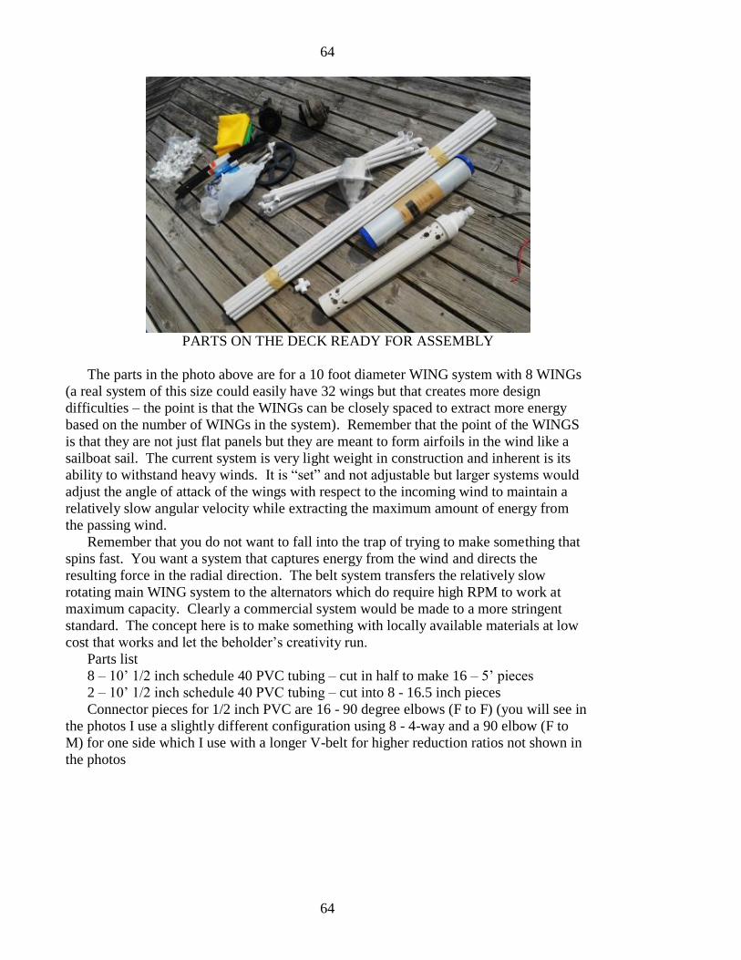
64
64
PARTS ON THE DECK READY FOR ASSEMBLY
The parts in the photo above are for a 10 foot diameter WING system with 8 WINGs
(a real system of this size could easily have 32 wings but that creates more design
difficulties – the point is that the WINGs can be closely spaced to extract more energy
based on the number of WINGs in the system). Remember that the point of the WINGS
is that they are not just flat panels but they are meant to form airfoils in the wind like a
sailboat sail. The current system is very light weight in construction and inherent is its
ability to withstand heavy winds. It is “set” and not adjustable but larger systems would
adjust the angle of attack of the wings with respect to the incoming wind to maintain a
relatively slow angular velocity while extracting the maximum amount of energy from
the passing wind.
Remember that you do not want to fall into the trap of trying to make something that
spins fast. You want a system that captures energy from the wind and directs the
resulting force in the radial direction. The belt system transfers the relatively slow
rotating main WING system to the alternators which do require high RPM to work at
maximum capacity. Clearly a commercial system would be made to a more stringent
standard. The concept here is to make something with locally available materials at low
cost that works and let the beholder’s creativity run.
Parts list
8 – 10’ 1/2 inch schedule 40 PVC tubing – cut in half to make 16 – 5’ pieces
2 – 10’ 1/2 inch schedule 40 PVC tubing – cut into 8 - 16.5 inch pieces
Connector pieces for 1/2 inch PVC are 16 - 90 degree elbows (F to F) (you will see in
the photos I use a slightly different configuration using 8 - 4-way and a 90 elbow (F to
M) for one side which I use with a longer V-belt for higher reduction ratios not shown in
the photos
65
65
You will also need 4- 4 way 1/2 inch schedule 40 connectors which act as the
center connectors inside the hub where the individual 5 foot PVC pieces come together as
noted in the photos below
1 – 24” – 3” diameter PVC heavy tubing (not the light weight sewer type)
Drill bit for plastic (see photo below)
8 yards of 60” wide nylon sail cloth and a sewing machine capable of cross stitching
(most home sewing machines will be more than adequate)
Pulley for 1/2 inch V-belt … this large pulley and V-belt was available in the farm
supply store but remember this is an example … you will have to locate your own design
hardware based on what is available in your area … the pulley in the photos only gives a
small reduction ratio and thus is not utilizing the alternators at full capacity but remember
this is only for example
V-belt 180 inch or larger (larger belts will allow for high ratio of WING to alternator
RPM reduction) – these are readily available on the internet if you cannot find at local
suppliers
Roll of Dacron string or for heavier applications you may use small diameter steel
cable – the PVC tubing needs a system of “stays” that link them together in a wheel
shape and maintain them rigidly connected as the wind works differently on the various
WINGS. You need to connect the WING tips together at the far edges and also stay them
to the hub (same principle as a bicycle wheel) – you will see a white hub in the photos
that is used to connect the stays
I do not state how I connect all of the hub pieces but basically they are both screwed
with small machine screws and glued with PVC glue. The glue by itself will fail with
stress of the WING system in operation but helps to hold the pieces in place when placing
the screws or other supporting structure.
2 used (or new if you like) automobile alternators – you can use with internal OR
external regulator types … if you use with the external regulator you can use smaller
gauge wire as this voltage is higher for the given output … the internal regulator
alternators are putting out a lower DC voltage and therefore require higher gauge wiring
… this is where you have to know what you are doing relative to electrical systems …
Larger WING systems may use DC motors that you purchase at places like Harbor
Freight or other suppliers and there are some 120VAC generator power heads available
commercially (meant for gasoline motor generator replacement parts). These offer 120
or 240 VAVconnection to standard “controllers” but once again these are for those who
have experience and knowledge of such systems.
The base is not shown in the system photos. Here once again this will depend on
whether you are placing this on the ground or on a tower or a roof top. The entire point
of course is that the WING wheel system is free moving on bearings (once again of your
choice) and is connected to the power generator via belt or other gear reduction system.
My personal investigations at this point are dealing with power wheels that are
integrated into the hubs of the system. One commercially available multi-blade system
uses magnets at the ends of the rotor blades. There are tradeoffs with any system and
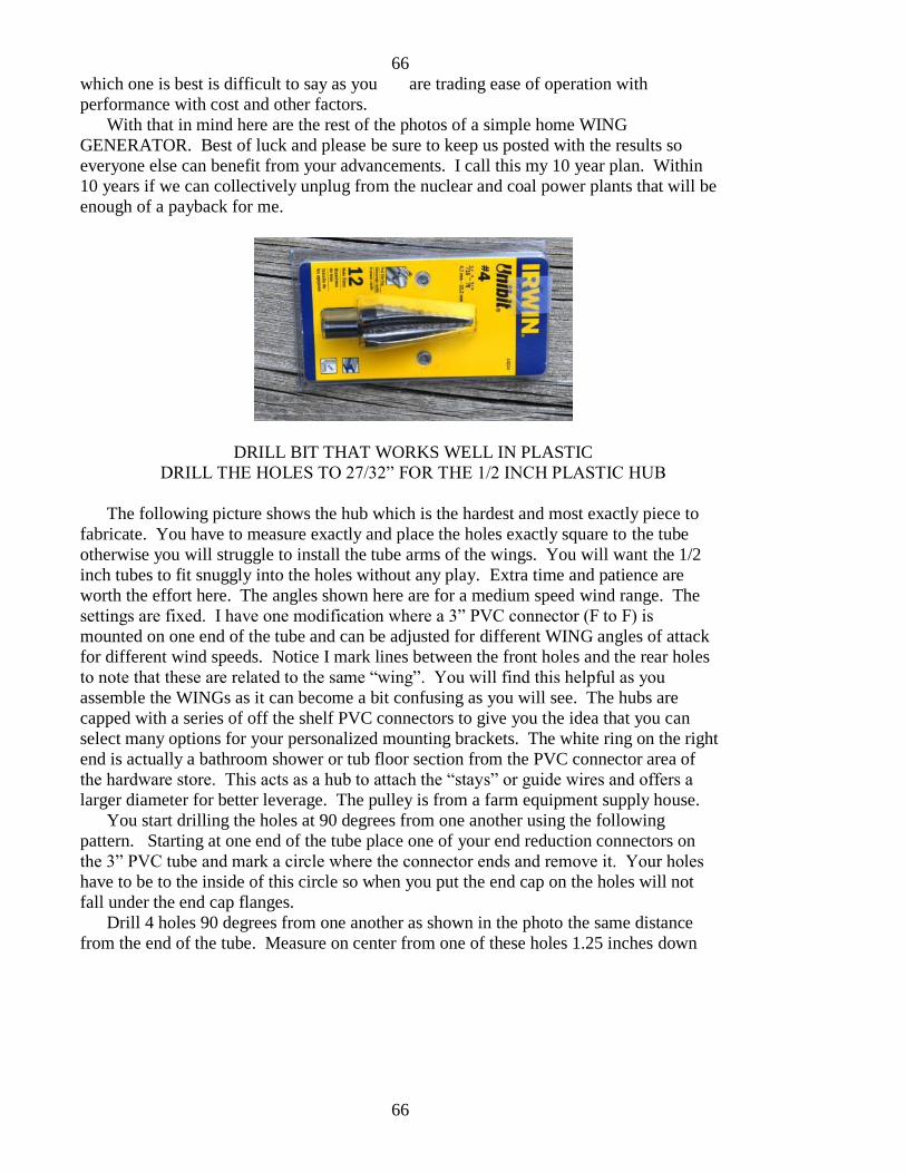
66
66
which one is best is difficult to say as you are trading ease of operation with
performance with cost and other factors.
With that in mind here are the rest of the photos of a simple home WING
GENERATOR. Best of luck and please be sure to keep us posted with the results so
everyone else can benefit from your advancements. I call this my 10 year plan. Within
10 years if we can collectively unplug from the nuclear and coal power plants that will be
enough of a payback for me.
DRILL BIT THAT WORKS WELL IN PLASTIC
DRILL THE HOLES TO 27/32” FOR THE 1/2 INCH PLASTIC HUB
The following picture shows the hub which is the hardest and most exactly piece to
fabricate. You have to measure exactly and place the holes exactly square to the tube
otherwise you will struggle to install the tube arms of the wings. You will want the 1/2
inch tubes to fit snuggly into the holes without any play. Extra time and patience are
worth the effort here. The angles shown here are for a medium speed wind range. The
settings are fixed. I have one modification where a 3” PVC connector (F to F) is
mounted on one end of the tube and can be adjusted for different WING angles of attack
for different wind speeds. Notice I mark lines between the front holes and the rear holes
to note that these are related to the same “wing”. You will find this helpful as you
assemble the WINGs as it can become a bit confusing as you will see. The hubs are
capped with a series of off the shelf PVC connectors to give you the idea that you can
select many options for your personalized mounting brackets. The white ring on the right
end is actually a bathroom shower or tub floor section from the PVC connector area of
the hardware store. This acts as a hub to attach the “stays” or guide wires and offers a
larger diameter for better leverage. The pulley is from a farm equipment supply house.
You start drilling the holes at 90 degrees from one another using the following
pattern. Starting at one end of the tube place one of your end reduction connectors on
the 3” PVC tube and mark a circle where the connector ends and remove it. Your holes
have to be to the inside of this circle so when you put the end cap on the holes will not
fall under the end cap flanges.
Drill 4 holes 90 degrees from one another as shown in the photo the same distance
from the end of the tube. Measure on center from one of these holes 1.25 inches down
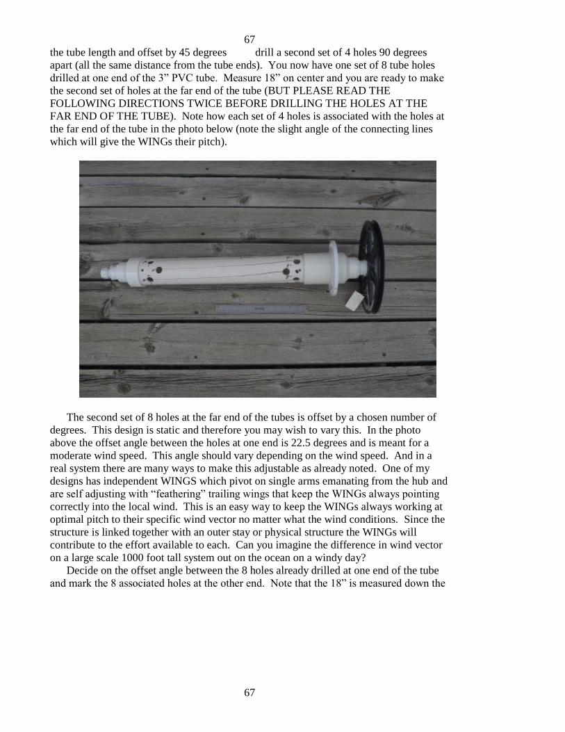
67
67
the tube length and offset by 45 degrees drill a second set of 4 holes 90 degrees
apart (all the same distance from the tube ends). You now have one set of 8 tube holes
drilled at one end of the 3” PVC tube. Measure 18” on center and you are ready to make
the second set of holes at the far end of the tube (BUT PLEASE READ THE
FOLLOWING DIRECTIONS TWICE BEFORE DRILLING THE HOLES AT THE
FAR END OF THE TUBE). Note how each set of 4 holes is associated with the holes at
the far end of the tube in the photo below (note the slight angle of the connecting lines
which will give the WINGs their pitch).
The second set of 8 holes at the far end of the tubes is offset by a chosen number of
degrees. This design is static and therefore you may wish to vary this. In the photo
above the offset angle between the holes at one end is 22.5 degrees and is meant for a
moderate wind speed. This angle should vary depending on the wind speed. And in a
real system there are many ways to make this adjustable as already noted. One of my
designs has independent WINGS which pivot on single arms emanating from the hub and
are self adjusting with “feathering” trailing wings that keep the WINGs always pointing
correctly into the local wind. This is an easy way to keep the WINGs always working at
optimal pitch to their specific wind vector no matter what the wind conditions. Since the
structure is linked together with an outer stay or physical structure the WINGs will
contribute to the effort available to each. Can you imagine the difference in wind vector
on a large scale 1000 foot tall system out on the ocean on a windy day?
Decide on the offset angle between the 8 holes already drilled at one end of the tube
and mark the 8 associated holes at the other end. Note that the 18” is measured down the
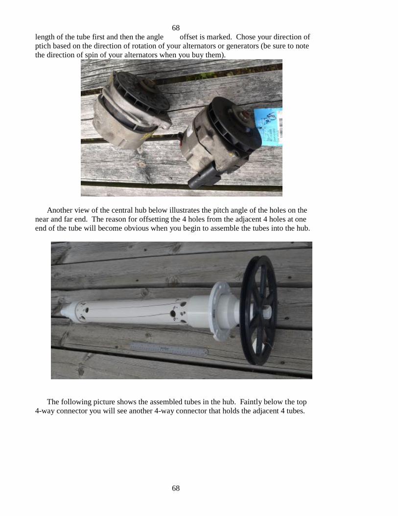
68
68
length of the tube first and then the angle offset is marked. Chose your direction of
ptich based on the direction of rotation of your alternators or generators (be sure to note
the direction of spin of your alternators when you buy them).
Another view of the central hub below illustrates the pitch angle of the holes on the
near and far end. The reason for offsetting the 4 holes from the adjacent 4 holes at one
end of the tube will become obvious when you begin to assemble the tubes into the hub.
The following picture shows the assembled tubes in the hub. Faintly below the top
4-way connector you will see another 4-way connector that holds the adjacent 4 tubes.
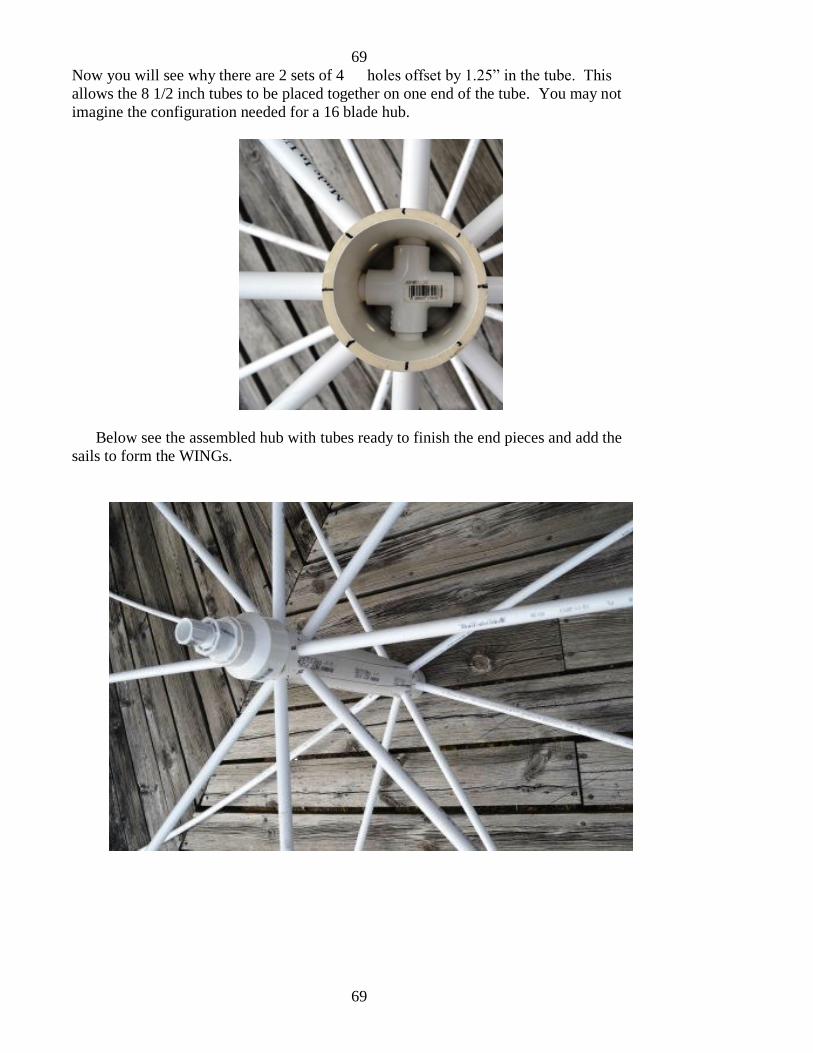
69
69
Now you will see why there are 2 sets of 4 holes offset by 1.25” in the tube. This
allows the 8 1/2 inch tubes to be placed together on one end of the tube. You may not
imagine the configuration needed for a 16 blade hub.
Below see the assembled hub with tubes ready to finish the end pieces and add the
sails to form the WINGs.
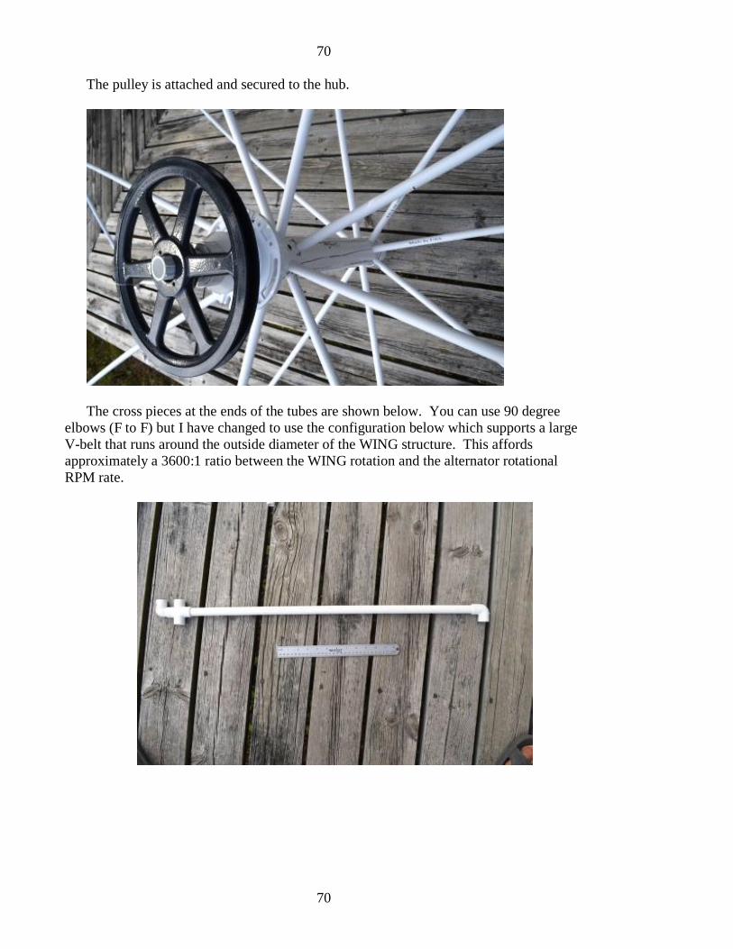
70
70
The pulley is attached and secured to the hub.
The cross pieces at the ends of the tubes are shown below. You can use 90 degree
elbows (F to F) but I have changed to use the configuration below which supports a large
V-belt that runs around the outside diameter of the WING structure. This affords
approximately a 3600:1 ratio between the WING rotation and the alternator rotational
RPM rate.
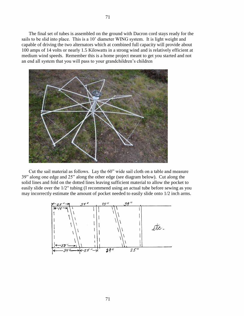
71
71
The final set of tubes is assembled on the ground with Dacron cord stays ready for the
sails to be slid into place. This is a 10’ diameter WING system. It is light weight and
capable of driving the two alternators which at combined full capacity will provide about
100 amps of 14 volts or nearly 1.5 Kilowatts in a strong wind and is relatively efficient at
medium wind speeds. Remember this is a home project meant to get you started and not
an end all system that you will pass to your grandchildren’s children
Cut the sail material as follows. Lay the 60” wide sail cloth on a table and measure
39” along one edge and 25” along the other edge (see diagram below). Cut along the
solid lines and fold on the dotted lines leaving sufficient material to allow the pocket to
easily slide over the 1/2" tubing (I recommend using an actual tube before sewing as you
may incorrectly estimate the amount of pocket needed to easily slide onto 1/2 inch arms.
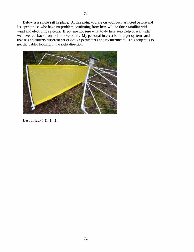
72
72
Below is a single sail in place. At this point you are on your own as noted before and
I suspect those who have no problem continuing from here will be those familiar with
wind and electronic systems. If you are not sure what to do here seek help or wait until
we have feedback from other developers. My personal interest is in larger systems and
that has an entirely different set of design parameters and requirements. This project is to
get the public looking in the right direction.
Best of luck !!!!!!!!!!!!!

73
73
IX. FAQs (Frequently Asked Questions)
This chapter could be very long but I have limited to a few fundamental questions
that most people would like to know. Just remember that we are in a complex
information war. Some people would like to enter an age of no modern devices and go
back to the day when food was food, a man’s word was based on the shake of a hand and
your house was your castle. We need energy and that need has been misdirected to make
us believe we need all the energy that is being consumed today. That simply is not true.
You must define your own footprint and hopefully reduce it. Think of efficient capture
and use of wind power as converting and using something that will be diverted naturally
anyway. We are just going to use some of it. We are not going to burn something to
make energy any more. That is an idea that must go away into the cave ages.
Automobiles and boats should be powered by the wind whether it is direct WING power
or via electricity generated by the wind. Then we will have true GREEN energy.
FAQ #1 - Is there hope to really power the world’s energy needs with a relatively
small number of large scale WING GENERATORs ?
ANSWER … yes … you have to understand that the practical energy output limit for
the large WING GENERATORS is equivalent to the nuclear or coal burning plants so we
can essentially replace them one for one. The expense of installing and maintaining a
large scale WING system is a small fraction of the expense of nuclear or coal and uses
the free energy of the wind. This is hard to imagine because of the gross failure of the 3-
blade wind generators that have gained the distain of people worldwide and given wind
power a bad name. Compare the output of a “large” 3 megawatt 3-blade wind generator
(about 15% of that which is only 450 kilowatts) with the output of a single 1000 foot
WING GENERATOR at 500 Megawatts that can replace a single nuclear power plant.
Compare the cost of operation with that of nuclear and coal and oil (and its derivatives)
not to mention the pollution or as in the case of nuclear the cost of spent fuel storage or
decommissioning a plant once it fails or ceases useful lifetime. The majority of nuclear
power plants in the USA are far past their expected life cycles but continue to have
renewed licensing from agencies that turn a blind eye to safety. They are burning high
grade bomb nuclear fuel for which they were never designed and an increasing amount of
energy is going to cool the spent nuclear fuel. If we fail to cool this fuel it will erupt and
one canister would potentially alter and even kill all life as we know it on earth.
FAQ #2 – how can we recoup the lost money wasted on the 3-blade wind generator
fiasco ?
ANSWER … countries must demand their money back literally. That money is in
the pockets of large corporations and immediately stop the government incentives that go
to these companies. Another approach is to cancel the offshore wind rights of the
companies installing 3-blade wind generators before it is too late and save these
installation sites for WING GENERATOR technology. Remember that the WING
74
74
technology offshore is totally different than the installation of 3-blade wind generators.
The 3-blade systems require large cement bases as footings whereas the WING systems
float or large barges and can be moved to any location. They can be brought into a
docking area for maintenance and remember also that all of the heavy equipment is at
ground level. No cranes or helicopters are required as they are completely maintained
from the staging area which is part of the main support structure of the WING
GENERATOR system. Plus they work to produce significant amounts of energy unlike
the 3-blade predecessors.
FAQ #3 – will the current book have an impact ?
ANSWER … My estimate is that with my open architecture concept within 10 years
at least some countries will be turning completely to my concept of DISTRIBUTED
ENERGY and national WING GENERATOR technology. Countries like the USA and
other western “advanced” countries will continue on the expensive destructive road of
nuclear and coal dependency and run their automobiles on gasoline. They will be
crushed economically by developing countries that will now have literally free energy
after their installation costs have been covered. Nuclear power will become a thing of the
past except where political forces keep it entrenched.
FAQ #4 – how long will it take to progress until the large scale 1000 foot WING
GENERATORs are online?
ANSWER … I have sound engineering information that these could easily be built
today with existing technology. That is why I present the large Ferris wheel photos in the
prior chapter presenting the WING technology. This technology already exists we
simply have to convert it a bit. I was ready to build these twice in my career (once in
2005 and again in 2009) but in both cases the efforts were scuttled for reasons I still do
not understand completely. But the point is that the engineering side of the coin is
already there. We just have to commit the resources (not necessarily money … I say the
resources which is very different) .
.

75
75
X. DISTRIBUTED ENERGY
We tend to think in old paradigms. Without knowing it your are conditioned every
day to accept the world as we see it today without questioning it. Local municipal
governments many times operate on remote control passing regulations based on “sound
management principles” without ever understanding that they are acting as gears in a
transmission of social norms that have been handed to you by people who do not exactly
have your best interest in mind.
Special interests set at every corner of government from top to bottom. At the heart
of all of this is dependency on the structure of energy as is marketed to us today. There
was an epoch of “peak oil” doom. The reality is that everyone repeated this like a mother
goose nursery rhyme. The reality is that the oil companies have identified so much oil in
the earth that 20 years ago they laid off the majority of geologists because they could
never recover the amount already identified. The real reason for the “peak oil” myth was
to keep oil prices high and the fear of returning to the Richard Nixon days of contrived
gas shortages with their long lines and to keep the people paying outrageous prices as the
pump.
The true story is that none of this should ever have happened in fact since the early
1900s the clear method of providing mass transit has always been with electric. Almost
all major cities sported an electric car system that was efficient in both cost and
maintainability. But all this was torn out to maintain Detroit and the auto industry. At
the helm has always been the oil industry pushing gas guzzling 4000 pound cars to
transport 150 pound people. The current world continues with that trend.
There are two parts to DISTRIBUTED ENERGY. The first is energy production and
one may imagine that we already have that. The only problem is that the energy sources
have to burn something to create heat which powers turbines. Alternative energy has
always been just that … you may as well preface “alternative” with the word
“subordinate”. It is one of those socially accepted norms that alternative energy is puny
– small – insignificant – a thorn in the side but a necessary evil to energy companies and
politicians who can boast GREEN while not providing anything real.
The reality is that the WING GENERATOR systems can and will (after a long and
bloody fight) provide real energy for the world. So the first aspect of DISTRIBUTED
ENERGY is the production and transportation of energy to the end user. A major
difference is that as with any COOP concept the average person should be able to buy a
portion of the energy generation equipment and in doing so own his portion of the facility
and therefore should receive his electricity for free based on the degree of ownership. But
the energy companies will not let that happen as they essentially make their money by
converting inert matter into heat and creating electricity from that source. It is not in
their financial best interest to change and it certainly is not in their financial interest to
acquire an energy source that is free. It has been like this since Westinghouse purchased
the first functional energy generation equipment from TESLA in the early 1900s. In a
76
76
later chapter I briefly discuss the Tesla story which is buried in misinformation
pawned off on the unsuspecting public.
An essential part of the generation of electricity will be in the future adoption of
energy production on site. At the factory or home, the waste of remote energy production
and distribution can be eliminated by onsite energy production and a further vast savings
occurs by eliminating the cycle of conversion to electricity which ultimately must be
reconverted to some useful form of work or energy. All of these conversions take an
enormous bite out of the energy equation and are literally wasted with no return on
investment whatsoever. Once again the energy companies have no interest in providing
incentives for you to become energy independent. They rely on the fact that current
technology is prohibitive in cost and even if one bears the expense it will never produce a
smidgeon of energy relative to the total needs of the user base. They have a monopoly
and they comfortably set on their laurels with no competition since they are licensed by
government entities which prohibits the slightest hint of competition.
The second aspect of DISTRIBUTED ENERGY is the function and form of what
happens to the electric energy once it is distributed. Once again the energy companies
rest on the monopoly they hold and produce just the amount of energy necessary for users
at a given moment. DISTRIBUTED ENERGY requires that the end users take energy
when it is ample and store for times when it is not as available. The term is called
buffering. We buffer food, water, manufactured products and almost everything else
related to our lives. But good old monopolized energy, we pay for it as we use it and that
is the only way it is available. Once again no one questions this daily “fact of life” and
we pay increasing costs offering it up to economic trends out of the control of mortal
man. This is complete BS but the average man cannot see his way out of this since all of
it is locked within the bowels of government agencies who are controlled by the energy
interests that they are designed to oversee.
Alternative energy such as the banks of 3-blade wind generators were supposed to
help but they turned out to be nothing more that a method of government to kick back
money directly into the coffers of big energy interests and these programs were designed
for failure from the onset. They were designed to use up all the GREEN money pools
and when they failed the angry public would sound the battle cry NOMORE !!!! playing
into the hands of the large energy companies who were poised to keep raising prices out
the roof tops and into orbit. Alternative energy especially at the local level would be
stymied forever. The current system of delivery prohibits DISTRIBUTED ENERGY.
In a true DISTRIBUTED ENERGY world the energy would come from the simple
maintenance costs of a relatively few remote large scale WING GENERATOR systems
and the people and industries would store energy locally as well as use direct drive
WING assist as a method of offsetting the conversion distribution inefficiencies of the
larger scale grid. Then entire point of the WING technology is that it efficiently converts
wind (available day and night all over the world) to electrical or direct energy and with a
properly designed system would provide the energy necessary for society to function.
This for the first time it would allow society to set back and really analyze its usage of
energy and start controlling energy rather than visa versa.
77
77
XI. The Myth of Alternative Energy
This is a topic I have lectured on publically many times and have been guest on major
international radio programs. It is something I know about and have studied the
intricacies of the deception occurring worldwide over the decades. I knew many people
because of my professional positions that for example worked in the oil industries or
other high level places
For example a man named Bill Paulec (now deceased) called me one day and
introduced himself. As it turned out he had many connections in many of the industries
and in particular was in the central computer rooms handling security of some of the
largest oil installations in the world. At one point all the geologists he knew were being
let go from their positions. It was because the oil companies had discovered so much oil
that they could never harvest it all. It was at the same time when the wave of “peak oil”
misinformation was making its way across the public horizon and repeated into reality.
The world of energy is filled with myths. I discuss many of these in my previous
books such as the myth of “fossil fuels”. There is nothing fossil about oil or coal or the
high oil content of some coals compared to others. The reality is that oil if found all over
the world in deep ocean basins and sometimes in pockets as deep as 24,000 feet under the
surface of the earth. Where were the fern forests and dinosaur bones that created these
pockets of black gold? Clearly the standard science that is being pawned off on the
public has nothing to do with any form of reality. But people repeat it as if it were the
Gospel Truth.
The reality that we think we perceive regarding alternative energy is filled with myths
and misconceptions sometimes due to the bumbling industries trying to sell a product or
sometimes planted there to protect the large energy producers. Let us look at the various
alternative energy sources and see if any have the ability to pass the criteria set forth
earlier in this book. That single criterion was simply that the alleged planet saving
technology has the ability to economically (on its own feet without government
subsidies) provide the equivalent amount of energy 24/7/365 currently produced by the
energy sources which convert heat to energy including nuclear – coal – oil – natural gas –
and in fact the small contribution of alternative energy sources that amount to far less
than 1% of overall energy production but generally at great subsidized expense.
There are two aspects to any analysis. The first is the financial investment to bring
any system on line and the pay back cycle. The second is the amount of available energy
in the source that would be 24/7/365 available and its ability to coordinate into the other
forms of energy production.
Wind – in its current form the 3-blade wind generator is simply a fiasco. It absorbs
by far the most government subsidy money and by its very existence prevents any other
possible alternative energy sources from ever coming online. Wind is the largest source
of power on earth so there is plenty of available wind energy. It blows day and night no
matter where you are and in a distributed energy world the time average wind energy is
essentially a constant. Unfortunately the 3-blade wind generators simply do not produce

78
78
any power and even at peak performance would not economically replace the major
sources of heat conversion energy systems. They should never have been implemented
but have been used as a symbol of green energy to gain political edge and kickbacks that
are highly profitable. The public will have a hard time overcoming the ongoing wave of
negative sentiment that has occurred over past decades. Like a wronged lover the scars
will never really heal. The GEs and SIEMENS have succeeded in destroying any hopes
of harvesting the one true source of energy that the earth has to offer.
The WING GENERATOR systems on the other hand do meet all of the requirements
for distributed large scale energy production with a national plan would provide 24/7/365
power to the entire nation and replace all other forms of energy.
Solar has been actually one of the main bright spots in the alternative energy world.
They are low maintenance once installed and they last a very long time. Once in place
you pretty much forget about them. The only problem is once again their expense vs.
heat conversion electricity with little hope of long term payback. I personally am
working on a possible physics solution that may advance the world of solar energy but
even with major breakthroughs and advancements the world of solar electrical conversion
cannot replace the level of power needed in the world. They will always be used as a
supplement but never a main source of power for general needs.
Hydro was the great hope of alternative energy and the early electric facilities were
based on hydro. It was the original best source of energy and you did not have to burn
anything. The Hoover Dam has a maximum capacity of over 2 Gigawatts but look at the
cement. You would not want to build it at today’s cement and construction prices. I was
just at the Hoover Dam and it sets idle with the generator water towers standing naked in
the empty lake bed. With the California drought of many years this monument to man’s
electrical world stands as an emblem of failure and dependency on rain in the middle of
the desert. China is making use of hydro but is having many difficulties in the mega
dams due to faulty construction. Big things are hard to engineer. The USA buys a lot of
hydro power from Canada which is a money maker for the country with the richest water
resources on the planet. Unfortunately the Canadians are not reaping the benefits from
this cheap electricity as their electric bills skyrocket. This is why governments cannot be
allowed anywhere near energy because they will always find a way to divert its benefits
from the people who paid for it and sell it through the backdoor to make a profit for their
business buddies.
The reality of hydro is that it can be inexpensive after the initial investment. But in
the case of the Hoover Dam in the middle of the desert, a handful of large WING
GENERATORS setting in the open desert nearby would rival the output of the dam and
at far less expense. If hydro is available it is a very good green source of energy but it
fails on the single criteria for providing all of the world energy needs. It simply will
never produce that level of energy even if we dam all of the world’s largest water ways.
The sum total available is not at that level. It is one source that should be utilized
wherever possible BUT if the cost of the facility is too large as in china they would be
better off using WING technology and letting the fish have the river.
79
79
Ethanol is one of my favorite “green” fuels as done in Brazil where they convert
sugar cane into fuel at the local level where it is refined and by process of reinvesting into
an expanding industry have grown to be the largest user and exporter of ethanol in the
world. You cannot buy a gasoline powered car in Brazil. You can fill your gas tank with
ethanol then fill your glass and drink it too (actually not a great idea but the idea is that
try that with gasoline and see where it gets you). When the Brazilian ethanol burns it
converts to CO2 and water which then can be reused by the sugar cane to grow to convert
more sunlight into more fuel. It is a very “green” system. For a country like Brazil it
does meet the one condition LOCALLY but it will not convert the world to biofuel.
Using corn to make ethanol however is not the same story. The government
subsidized bio fuel programs in the USA were total disasters as they discovered it took
almost as much fuel to produce and refine the ethanol as the benefit. Without
government subsidies it would never have seen the light of day. Additionally many
people in the world starved to death due to the sudden rise in grain prices triggered by
corn price futures. But on the final board of analysis the corn biofuel would never begin
to hold a candle to offset world energy production.
A success turned failure occurred when the Hawaiian state government passed a
“green” bill with good intentions that went bad. They gave a time period requiring that
all gasoline would have to have a certain percentage of ethanol. When the date came
there were no local sources of ethanol so they ended up having to purchase from
mainland ethanol suppliers and have it shipped to the islands to satisfy the law.
Water tide and wave energy generators have never been practical. They individually
produce very little energy especially from the cost of construction are not a practical
solution (paving the ocean with bobbing floats). Even on a local scale they cannot
produce enough useful energy. In my opinion they are yet another example of an energy
technology funded that would never make a difference. This is the common thread of all
the alternative energy projects that I have seen funded over past decades.
Another example of a great looking idea but one that has little to no practical value is
an aerial balloon wind tunnel device with a 3-bladewind generator mounted in the tube.
In the advertisements and promo literature it looks like a great idea but let me see this
operate in a gusty stormy lightning filled sky and attempt to manage this let alone derive
any real power from the generator. Part of the problem with any form of electrical
generation is the cable size to bring the power to a location where it can be converted to a
higher voltage for transport. Low voltage systems require high current capacity wiring
and this would seem to be a limitation on anything up in the air. A similar device has a
kite that flies on a tether and the pulling on the tether is translated into power on the
ground. Once again this looks good on a nice sunny day but try to manage this when the
stormy skys set it. The final reality is that although one may derive some power from any
of these devices they will never solve the world energy problem and further solidify the
concept that alternative energy is a field of novel ideas that can never produce real
amounts of energy that will replace burning high energy content fuels for primary energy
needs.

80
80
Geothermal stands in the same boat as the rest of the traditional alternative energy
sources. It is expensive to install and the payback is questionable. It only works in
certain places and it will never solve the world energy needs.
When I set out to design a system that would truly match the world energy output
requirements that was my primary goal. One needed an energy source available 24/7/365
in all parts of the world. You needed to capture that energy on a large scale so the end
units had to scale up to very large sizes. They had to contribute to a distributed energy
concept and be inexpensive to build and maintain relative to traditional energy sources
including nuclear – coal – oil and the other less important sources of energy.
The WING GENERATOR fills all of the requirements.
.
.
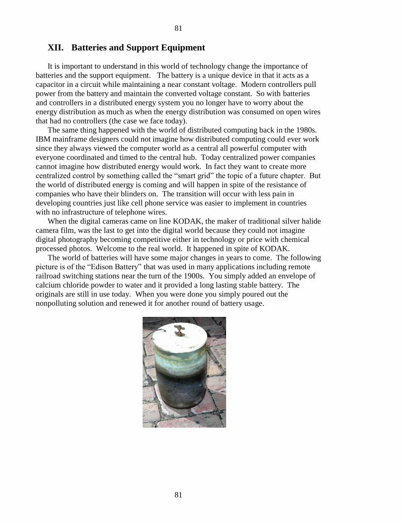
81
81
XII. Batteries and Support Equipment
It is important to understand in this world of technology change the importance of
batteries and the support equipment. The battery is a unique device in that it acts as a
capacitor in a circuit while maintaining a near constant voltage. Modern controllers pull
power from the battery and maintain the converted voltage constant. So with batteries
and controllers in a distributed energy system you no longer have to worry about the
energy distribution as much as when the energy distribution was consumed on open wires
that had no controllers (the case we face today).
The same thing happened with the world of distributed computing back in the 1980s.
IBM mainframe designers could not imagine how distributed computing could ever work
since they always viewed the computer world as a central all powerful computer with
everyone coordinated and timed to the central hub. Today centralized power companies
cannot imagine how distributed energy would work. In fact they want to create more
centralized control by something called the “smart grid” the topic of a future chapter. But
the world of distributed energy is coming and will happen in spite of the resistance of
companies who have their blinders on. The transition will occur with less pain in
developing countries just like cell phone service was easier to implement in countries
with no infrastructure of telephone wires.
When the digital cameras came on line KODAK, the maker of traditional silver halide
camera film, was the last to get into the digital world because they could not imagine
digital photography becoming competitive either in technology or price with chemical
processed photos. Welcome to the real world. It happened in spite of KODAK.
The world of batteries will have some major changes in years to come. The following
picture is of the “Edison Battery” that was used in many applications including remote
railroad switching stations near the turn of the 1900s. You simply added an envelope of
calcium chloride powder to water and it provided a long lasting stable battery. The
originals are still in use today. When you were done you simply poured out the
nonpolluting solution and renewed it for another round of battery usage.
82
82
The Edison batteries were connected in series and parallel to make any size battery
for the particular application. Since Edison could not patent sea water (a natural battery
solution) he changed the solution to the next element in the periodic table to get his
patent. Today the lead acid battery actually duplicates ancient designs that used apple
vinegar in a clay pot found in remote archaeological sites.
The Atlantians were said to have used sea water batteries and in remote areas of the
South China Sea it is said that their large battery casings are still by the ocean side where
the daily tides filled the containers with wires leading inland. I once was giving a talk to
a large audience where I was discussing the use of sea water batteries and a scientist from
the navy later confirmed that I was correct in my analysis.
I often talk about an old technology that is actually being produced in china … a
water battery. Whatever the future of batteries one can imagine even relatively low
efficiency batteries in the home may be large as a water heater. They simply set there
and are never moved so it is not like in the transportation industry where weight is a
factor.
Modern Li-Ion batteries are always being improved and are used in banks of small
batteries in the Tesla Roadster automobiles. The owner of Tesla is in the process of
building a battery factory that will drive the price of car battery packs down for electric
cars. At this price they would also start to become practical for distributed energy
applications in the home and industry. As I have stated before you do not need a battery
pack in the home or industry to drive all your energy needs, instead it acts as a buffer and
inexpensive voltage stabilizer in the world of distributed energy driven by WING
technology.
.
83
83
XIII. Tesla Power Feasibility
Many years ago I rediscovered the principles used by Tesla to extract energy from the
vertical electric field of the earth powered by the ionosphere to ground capacitor. I
realized that Tesla did not know where the power source originated but he certainly knew
it was there and how to tap into it. My work not only rediscovered the work of Tesla but
also identified the source of energy in the earth’s discharge of the solar capacitor as
outlined in my previous work. My early book “Atlantis to Tesla – the Kolbrin
Connection” outlined my discovery and within weeks of the release of that book a series
of events indicated that the US black ops constructed a Tesla Tower west of Ottawa in
Canada to try to gather power as described in my book. As they powered up the tower it
required more and more power as they drilled an electrical path through the dielectric of
the atmosphere. They needed more power than could be provided by the Ottawa nuclear
power plant so they requested more power to cross from the US northeast corridor to pass
to Canada. At this point they completed the “hole” to the ionosphere and the resulting
current from the ionosphere blew out the Ottawa nuclear reactor and backed up nine
nuclear power plants on the east coast from New York to Washington DC. This was the
true cause of the famous north east power outage. The official story is that a squirrel tail
fell across a power line in Ohio and caused the fiasco.
My home page announces that I have been embarking on a project to develop Tesla
Tower technology for commercial power however I have come to the conclusion that
although it meets the single criteria for world power production it also is a very
dangerous source of power since it is electrically connecting the grid to an immense
power source outside the planet over which we have no control. Once a current surge
begins there is no way to turn it off.
I have come to the conclusion that the wind power of the earth is THE one reasonable
and true source of energy that we need to tap for world energy production. That is when
I seriously began to research the way to harvest that energy on a scale commensurate
with other forms of energy production. The results are presented to the public in this
book.
With that I want to tell the true story of Tesla as history has distorted his work beyond
recognition. Today people are told that Tesla built his tower to transmit electrical energy
rather than use an electric grid. This is myth and you will now understand why. The
myth was created because the energy controllers know full well that if the people found
out that all these decades they have been paying for energy that is in abundance all
around us for the asking there might be a few lynchings. The reality is that Tesla had just
sold his entire system of power generation and distribution to Westinghouse for an
approximate $4 Million price tag. Of course there was a non-compete clause preventing
Tesla from using this technology to compete against Westinghouse. So the question I
have to ask those who promote the idea that Tesla intended to transmit power via his
tower … where exactly was he supposed to get the power to transmit?
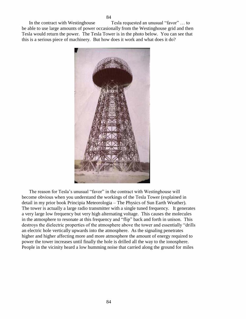
84
84
In the contract with Westinghouse Tesla requested an unusual “favor” … to
be able to use large amounts of power occasionally from the Westinghouse grid and then
Tesla would return the power. The Tesla Tower is in the photo below. You can see that
this is a serious piece of machinery. But how does it work and what does it do?
The reason for Tesla’s unusual “favor” in the contract with Westinghouse will
become obvious when you understand the workings of the Tesla Tower (explained in
detail in my prior book Principia Meteorologia – The Physics of Sun Earth Weather).
The tower is actually a large radio transmitter with a single tuned frequency. It generates
a very large low frequency but very high alternating voltage. This causes the molecules
in the atmosphere to resonate at this frequency and “flip” back and forth in unison. This
destroys the dielectric properties of the atmosphere above the tower and essentially “drills
an electric hole vertically upwards into the atmosphere. As the signaling penetrates
higher and higher affecting more and more atmosphere the amount of energy required to
power the tower increases until finally the hole is drilled all the way to the ionosphere.
People in the vicinity heard a low humming noise that carried along the ground for miles

85
85
around when Tesla was operating his tower. The same sound people reported
hearing near Ottawa before the northeast power outage.
At this point it is like any capacitor whose dielectric breaks down; all of the current
comes pouring down the path in an uncontrollable avalanche. When Westinghouse found
out what Tesla was doing he sent a pack of goons out and had the tower torn down. He
realized that Tesla could derive free power from a natural source and undercut is heat
conversion electrical generator pricing that he intended to sell to the public forever. The
story was changed to state that Tesla was going to distribute energy but as I said, where
was he supposed to get the energy to transmit? The tower clearly is standing all by itself
in the middle of a field with no power generation equipment anywhere in site. Even a
modern Hollywood movie depicts a young Tesla transmitting energy but Hollywood does
not have to explain where the energy supposedly came from.
86
86
XIV. Electric Cars and Distributed Free Energy
For those who are unfamiliar with electric cars they were actually in production in the
early 1900s. They were certain to beat the gasoline automobile for simplicity and ten
other reasons. So why did they not catch on?
That is why I call the 20th
and this first part of the 21st century the “black century”.
The real developments were sidetracked and kept out of reach of the public. People
simply do not understand how they have been manipulated through world wars,
government control of their lives and a model of society that strains at reason and with
the main controlling factor being energy.
Electric autos are in the future and I plan to purchase on as soon as they come down
in price. I may even try my hand at creating some electric cars. The current trend is to
duplicate the styles of cars to look somewhat the same as gasoline powered cars although
the electric car styles are far advanced from anything put out by the traditional “Detroit”
auto machine.
Refueling stations are going to become more common and all the required support
structure is going to be in place. It is going to be far easier to implement the electric car
support infrastructure than it would be if we were to convert from electric to gasoline
because of the inordinate amount of maintenance required by the gas guzzlers.
All of this is already happening and will continue in spite of resistance at every turn.
The real crux of the matter simply comes down to the source of electricity. If you
convert high heat content fuels to generate electricity then any economy of scale will be
offset by the fact that it is adding more energy demand on traditional energy supplies.
Along with buying my own electric car will be the knowledge that I am charging the
batteries with my very own WING power. My car will also sport a collapsible roof top
WING GENERATOR that will flip up when I am parked to recharge the batteries day
night.
In my own design I may have a car that is directly powered by a WING system and
pushes the excess power to the battery pack. Ultimately I want my electric power to
come from my financial share in a full scale remote WING system and delivered to me
on the public grid where I know I am getting true green energy.
.
.

87
87
XV. World Domination of Major Industries
In the pretend world of the Monopoly Game we have all lost and won as we played
with our friends. However in the real world game of monopoly, the winners have taken
their Boardwalks and Park Places and the game never ended. After putting hotels on
those they continued to take over the money industry, the war industry, politicians,
courts, legislatures … the list is endless. The one thing that is sure is the YOU were not
in the winner’s circle and never will be.
A long time ago I defined for myself what I call “free living”. It is my version of the
pioneers who forged the old west. There was no place to spend money. Other things had
value. In my list I tried to plan my future so I had no expenses for housing,
transportation, food, water, communications, and where I had time freedom to pursue my
interests in spite of the fact that I was not rich.
I defined where I wanted to dedicate my time in science and engineering. What you
see of my work is a result of that planning. I did not choose what I was going to do willy
nilly but defined the needs of man in general. The way I could live my life would be a
model for others to follow since this would alleviate the stresses on the world resources
so we had something to pass to the future generations.
I was not the only person looking for a better simpler life. Some think this means
living in a cave and eating roots from the nearby woods. Nothing could be farther from
the truth. In my travels I have come across areas where the people are happy, do not have
locks on their doors, have abundant food and clean water and take care of their elderly
into old age without government assistance. There is a myth that one must have a lot of
money to be independent. To the contrary I see people with money as those who do not
seem to really be happy. I do see some people with money who use it for the betterment
of the world and when I see these people’s faces I see people who are satisfied with their
lives.
The world is controlled by a dark side that is real. They use many intermediate
people including who we think are our “leaders” who are nothing more than middle
management in a worldwide control racket that has most of the people fooled. These
people rule by lies and deception. The leaders are handpicked to be people who can sell
you anything by telling you how good it will be for you and how they have your best
interest at heart, only to find out after the fact that you have been had again.
By then the next group of elected liars are in place and the sheeple are following that
pack of lies hoping for something to turn out better. The major industries are controlled
by the same group of people on planet earth. Our ability to resolve the international
energy issues is paramount to a decent life. There is more than plenty for all but the
leaders are under the misconception that if someone at the bottom rises up an inch, it will
take from their power and wealth.

88
88
XVI. Myth of the “Smart Grid”
You are being told that you need to spend billions of dollars to upgrade the national
electric grid to protect it from EMP (electro-magnetic pulse) whether man made or from
natural causes. The simple reality is that if an EMP is racing through our grid there is no
such thing as a smart grid that will stop or prevent anything. The simple reason is
because an EMP moves at the speed of light and by the time the “smart grid” has detected
it at a certain point the EMP has already passed, done its damage and is racing to the next
grid element at the speed of light to wreak havoc in the next grid element.
Possibly the middle manager president Obama has solved the mystery of faster than
the speed of light transmission or possibly his scientific advisors are smoking something
strange. The real reason for the smart grid is to monitor all activity on the grid. It has
NOTHING to do with grid safety. The grid safety depends on technology that has been
present for over 100 years in the form of shunts and diodes. These react as passive circuit
elements to counteract surges as they happen.
The WING GENERATOR systems do not require any changes to the grid system that
is presently in place. Since they are capable of replacing the large scale heat conversion
power plants and collectively maintaining constant voltages on the grid along with
distributed battery controller equipment in the distributed network, they can be adapted to
the grid without any smart technology.
These are topics which I discuss every week on my commercial free radio show so be
sure to listen for more details on this and other related topics.

89
89
XVII. Proposals and Prior Funding Efforts
The following is an example of one of the proposals that led me down numerous
funding efforts over the past years. These were funded and as we were ready to
proceeded with engineering studies and procurement the financiers literally disappeared
and I have been unable to locate or communicate with them since. The name have been
removed in the duplication below.
WIND – NEXT GENERATION
COMMERCIAL POWER SYSTEMS
PHASE-I
James M. McCanney, M.S.
In coordination with
xxxxxx Companies, Inc.
xxxxxxxx Street
xxxxxxxxxxxxxxxxxxxxxxxxxx
In Agreement Based on
Confidential Disclosure Agreement
Dated May 25, 2005

90
90
WIND – NEXT GENERATION
COMMERCIAL POWER SYSTEMS
PHASE-I
ABSTRACT
Of the four major areas of Green or renewable energy sources, wind energy is taking the
leading role in the alternative power industry. As efficiencies in large commercial wind
generators continue to increase, the projections for growth by industry experts suggests a
500% expansion of investment and power generation over the next five years. Power
companies are also providing incentives to offset peak energy demands, preventing the
need to build new large-scale power facilities based on coal, natural gas or nuclear power.
Over the past 10 years Physicist James McCanney has analyzed the progress and
development of the alternative energy generation industries. There are new technologies
available in 2005 that allow an entirely new breed of Next Generation Wind Commercial
Power Systems to be introduced. Based on planning and development meetings with the
well-established company xxxxxxxxxx Companies, Inc. there is a business opportunity to
build and commercialize the new breed of wind power systems,
It was decided that there are many associated commercial applications and that a first
effort PHASE-I plan would propose a prototype product line of Next Generation
industrial wind generators that would
1) be placed on location primarily in secured housings on the roof tops of
commercial industrial buildings (eliminating the tall pole windmill structures),
2) increase the efficiencies of both the wind retrieval systems for low to moderate
wind speeds (by innovative new fan systems),
3) increase the efficiency of the power delivery system (since the power is locally
available at the industrial site it eliminates the power loss due to conversion to
electricity and transport) and
4) to place a realistic goal of reducing the annual energy bill by 30 % for light
industry.
In conjunction with this project will be the initial designs of the wind generator housings
as well as the control systems that will automate their management as they are integrated
into the existing energy needs of the various users. Follow on projects are already
anticipated. For example mobile high efficiency emergency wind generation systems
could be located in strategic locations or moved via trucks for small, medium and large
91
91
applications. Another follow on application is to retrofit existing wind farm
towers with the low wind speed high efficiency Next Generation Fan Blade System.
An additional effort in the PHASE-I proposal is to study energy storage systems and to
increase their use in such wind systems to enhance the storage of energy on site and
further reduce the inefficiencies of energy conversion and transport.
PROBLEM / OPPORTUNITY
There are inherent losses of energy in all energy production and transport systems.
Commercial energy from utility power plants operates on an average of 33% conversion
of “energy in” (e.g. the heat of burning coal) to electrical “energy out” (e.g. electrical
energy actually placed on the electrical power grid). Another 5 to 10 % loss occurs in
transporting this energy to the substations and there are further losses in the lower voltage
distribution (in local power lines) and inside the industrial building itself.
An average electrical motor at an industrial site, although possibly capable of 90 %
efficient at capacity loading, are on average run at far lower efficiencies. Industry wide
use of electrical power shows that a combined 64 % of all the electrical power generated
in the United States (and other industrial nations) is consumed by industrial electric
motors. These facts are staggering. This means that of the total amount of energy
initially produced in the commercial power plants, only about 10 to 15 % if the initial
energy burned to produce electricity is actually utilized to produce useful work at the
industrial site.
In addition to the electrical needs of everyday business, the greatest demands at summer
peak season are air conditioners and compressors. Once again, based on the inherent
inefficiency of the cooling cycle, only a small fraction of the energy consumed is
converted to cooling a building.
The Next Generation Wind system will reduce the losses inherent in the traditional
commercial energy production and delivery systems by being on site and directly
providing “assist energy” to drive motors and compressor systems. On location power is
the most efficient delivery system and in many cases there will be no need to convert the
wind energy to electricity as it can be used to directly assist existing electrical compressor
motors, based on the available wind.
Additionally, the concept of the Next Generation Wind System is to perfect a new set of
high efficient fan blades that operate at all wind speeds but especially in low to average
winds which are most common in the average city.
The efficiency curve for currently available commercial wind generators shows that they
will produce peak power at 28 to 35 mile per hour wind speeds, but only produce about a
92
92
10th
of peak power at average wind speeds of 10 to 15 miles per hour. Thus, the
modern wind farm with traditional tower and 3-fan blade system will only trap and utilize
about 5 % of the wind that is passing through the blade system on an average day. After
transport and distribution the amount of usable work from the overall system is further
reduced as with any commercially produced power source.
Retrofitting existing wind farm towers with the Next Generation Fan Blade systems is a
major goal of the follow on projects to this Phase-I proposal. These future plans will also
include the use of “wind dams” to produce energy levels unheard of in current
commercial wind systems.
BACKGROUND
Extensive references and commercial documentation exists for the current wind
generation industry. Included here are a number of key references that will support the
claims and foundation of the current proposal.
Electrical Cogeneration Regulation and Information
Xcel Energy Inc., the local electrical energy utility company, is compliant with Federal
and State laws in providing interface and interconnection specifications for co-producers
of electrical power under the rules set forth by Minnesota Public Utilities Commission.
CO2 Emissions from electrical generation compared to all other uses of fuel
According to the World Energy Outlook 2004 report, electrical generation of power
contributes more metric tons of carbon-dioxide emissions and pollution to the atmosphere
than all other uses of energy combined which includes transportation, industry,
residential services and other sources of fossil fuel consumption.
sourceguides.com listing shows over 20 major industrial corporations world wide
are actively involved in the retail business of selling and servicing large scale wind
generation systems and components
The existing and growing number of large companies worldwide that are now involved in
wind generation is difficult to follow in this time of unprecedented growth. With wind
now comprising less than 1 % of overall national energy production in the United States
and the growing need for averting peak energy overloads in the ever growing need for
electrical services, the next 5 years holds a remarkable market for those with insight into
the innovations that will overtake the market.
Many subordinate industries are arising just to support the Wind Generation growth
industry

93
93
On the July 18, 2005 the front page of the Duluth News Tribune is a lead article with
color photo showing a new large growth industry for dockworkers that are learning how
to ship wind generation equipment. Gaining a good reputation for this specialized
shipping requirement has given them a new line of work.
Minnesota is a leader in sustainable clean energy programs
The manual “DESIGNING A CLEAN ENERGY FUTURE: A RESOURCE MANUAL”
is distributed by The Minnesota Project, University of Minnesota Regional Sustainable
Development Partnerships and the Minnesota Chamber of Commerce. It shows many
Minnesota community and private industry projects dedicated to improving energy
resources and clean energy. It includes help for those who wish to develop a project from
start to finish.
naturalgas.org like many other organizations educates and informs with facts about
the energy production industry
The facts regarding the efficiencies of energy production and transport are readily
available. After the first wave of investment in wind energy and distribution, it is now
time to take a second look at the industry and make innovative steps toward the Next
Generation of high efficiency generators, rotor systems and energy delivery systems.
CAD – CAM software in design of new high efficiency systems
There are many excellent CAD – CAM software packages on the market today. An
example used extensively in aerospace and aviation is the Ashlar-Vellum software
package. This software allows for end-to-end system design including airfoil system
design using the most recent algorithms.
Existing studies on low speed air foils
Extensive databases exist in the public domain regarding low speed airfoil dynamics and
design. These can also be utilized in the design to maximize fan blade systems and bring
a new dimension to slow to moderate wind speed high efficiency rotor systems.
xxxxxx Companies, Inc design and manufacturing history
The ability to take the designs and specify with industrial grade precision and ultimately
to build, install and maintain equipment of all sizes and complexities makes xxxxxx
Companies, Inc. an important aspect of this PHASE-I proposal. They are a Union shop
with proven ability to work globally on complex projects. They also have associations
94
94
with many other industries with associated products lines such as industrial
compressors and control equipment.
OBJECTIVES
The Phase-I objectives are listed below. Essentially the goal is to finalize and implement
the NEXT GENERATION FAN BLADE SYSTEM innovative fan blade rotor designs
and integrate them into a commercially viable package for roof top industrial wind assist
to existing energy needs of light to medium industry, and to provide roof top cooling
compressor assist technology to any commercial building.
1) NEXT GENERATION FAN BLADE SYSTEM development will involve both
CAD – CAM modeling and incorporation of existing data bases on low speed
airfoil design to finalize the initial design criteria for the fan blade system.
2) Field trials of pre-beta site systems
3) NEXT GENERATION wind collection and fan housing unit development will
incorporate existing roof top high strength designs and adapt them for the purpose
of housing the fan blade systems and support control systems
4) Integration of control systems for the PHASE-I prototype wind system.
5) Beta testing site determination and engineering Functional Specification
6) Regulatory approval of Beta sites with local building codes and regulatory PUC
interconnection rules
7) Beta site test
8) Marketing analysis and projection of potential cost per unit energy savings for
consumers using NEXT GENERATION WIND SYSTEMS
9) Initial analysis of subordinate PHASE-II projects such as adopting the new high
efficiency low wind speed fan blade systems to retrofit existing commercial wind
tower generators, potable emergency wind systems, energy storage system
analysis, and the initial conceptual prototyping of wind dam systems.
WORK PLAN
The PHASE-I project is anticipated to be a 6-month project with all aspects of the project
beginning at same time and being pursued by the numerous players that will be involved
in the project. The following people will conduct project oversight. The division of
labor of oversight is general and there is expected overlap based on the needs of the
business.
Business and legal: xxxxxx, Business Development, xxxxxxx Companies, Inc.
Mechanical, CAD – CAM, production and installation: xxxxxxx, Vice President,
xxxxxxx Companies, Inc

95
95
Theoretical, CAD – CAM and design: James McCanney, M.S.
We anticipate that we are going to be developing core groups of individuals who will
grow with the organization and project. These subgroups will utilize whenever possible
the existing expertise at xxxxxx Companies and when needed find affiliate companies
that will provide additional expert consultation (as in the integration with compressor
systems etc).
The goal is to have within 6 months a working prototype in Beta test with at least one
local business and be able to produce meaningful analysis of a working system. All
systems will be designed with the goal of retrofitting new innovations, upgrades or
additional capabilities. Systems will be designed with a modular concept so they can be
mated to existing systems for expansion without the removal of existing systems.
A user-friendly maintenance free system is the goal. As with the systems that will
interface to the NEXT GENERATION WIND SYSTEMS, there is a need for rugged
maintenance free environmentally safe systems.
BUDGET
The following budget is based on a 6 month PHASE-I project total of $250,000 and is
divided into ten $25,000 divisions.
1) CAD – CAM engineering and design
2) HOUSING prototyping
3) Fan blade construction and testing (2 units of $25,000)
4) Theoretical and Design stipend – James McCanney (to be paid in 6 performance
based installments)
5) Procurement of control systems, interface interoperability equipment (2 units of
$25,000)
6) Beta site development and regulatory approval
7) Legal / patents
8) Manufacturing of final test unit, installation and Beta test
96
96
The following is a 2009 proposal meant to build the first 100 foot prototypes on a
remote private beach in western Mexico which ended when the financiers disappeared.
WIND – NEXT GENERATION
COMMERCIAL POWER SYSTEMS
MCCANNEY - FERRIS WING – WIND GENERATOR
PHASE-I
April 30, 2009
James M. McCanney, M.S.
Prepared for –
xxxxxxxxxxxxx
xxxxxxxxxxxxxxxxxxxxxxxxxxxx
xxxxxxxxxxxxxxxxxxxxxxxxx
MCCANNEY - FERRIS WING – WIND GENERATOR
ABSTRACT
Of the four major areas of Green or renewable energy sources, wind energy is taking the
leading role in the alternative power industry. As interest and demand for large
commercial wind generators continue to increase, the projections for growth by industry
experts suggests a 500% expansion of investment and power generation over the next
five years. Power companies are also providing incentives to offset peak energy
demands, preventing the need to build new large-scale power facilities based on coal,
natural gas or nuclear power. The reality of the currently accepted “3 blade system” is
that it is extremely inefficient at low to mid wind speeds which are typical even in high
wind production areas. The current proposal shows a much more efficient design at these
wind speeds and also can be scaled to extremely large systems capable or replacing a
significant portion of the world energy infrastructure with wind power. Construction and
maintenance of the new wind generator design is far easier because all of the heavy
equipment is readily accessible from the base of the support system.
Over the past 10 years I have analyzed the progress and development of the alternative energy industries. Wind is the only energy source that is consistent both day and night
97
97
and which operates under all weather conditions. The issues with current wind
designs are 1) limit on size, 2) inefficient energy collection and transfer at mid to low
wind speeds, 3) small power output relative to the world total power demand (it would
take millions of these towers to create the amount of power needed on a world scale) and
4) the maintenance of equipment that is hundreds of feet from the ground or water
surface in an enclosed tower and equipment housing.
There is a new technology available that will allow an entirely new breed of Next
Generation Wind Commercial Power Systems to be introduced, with a business
opportunity to build and commercialize the new breed of wind power systems on a world
wide scale.
Phase – I Proposal
The initial project is to design and build a 100 foot prototype that will be used to finalize
the fin and supporting structural designs to be scaled up in commercialization of larger
systems that are planned to reach over 1000 feet in future developments. Three drawings
are included in this draft proposal. A separate page describes the information given in the
3 drawings. Included in the Phase – I study will be some ongoing theoretical
investigations into other aspects of using the wind generators for direct drive systems,
however the sole intended use of the initial prototype development is to generate
electricity. The specifications and goals of the initial 100 foot McCanney – Ferris Wing
Wind Generator are as follows. The total energy available in the 100 foot circular area
in a 30 mile per hour wind is approximately 18 MWatts. Current 3 blade systems with
circular area coverage of over 200 foot diameter only produce a maximum of about 1.5
MWatts of electrical power and the efficiency curve drops off sharply with reduced wind
speed. The goal of the 100 foot prototype is to at least match the larger 3 blade system
output power and more importantly, capture a higher percentage of available wind energy
at mid to low wind speeds from a smaller diameter collection area. With data available
from the prototype and engineering experience gained in this effort the second generation
system would seek funding and engineering support to build a Wing Generator with 200
foot diameter with the intention of making the first commercially available system.
The rational for building a large scale higher efficiency wind generating system only
becomes apparent when the world energy requirements are matched with current systems.
An analysis follows the brief diversion regarding non-electric direct drive systems that
could also eventually be utilized with the same Wing Generator systems.
There are many associated commercial applications based on the first effort PHASE-I
plan which would …
5) be placed on location primarily in secured housings on the roof tops of
commercial industrial buildings (eliminating the tall pole windmill structures),
98
98
6) increase the efficiencies of both the wind retrieval systems for low to
moderate wind speeds (by innovative new fan systems),
7) increase the efficiency of the power delivery system (since the power is locally
available at the industrial site it eliminates the power loss due to conversion to
electricity and transport) and
8) system examples would include wind powered desalinization plants, geared direct
drive powering of factory equipment or pumping water
In conjunction with this project will be the initial designs of the wind generator control
systems that will automate their management as they are integrated into the existing
energy needs of the various users. Follow on projects are already anticipated. For
example mobile high efficiency emergency wind generation systems could be located in
strategic locations or moved via trucks for small, medium and large applications. An
additional effort in the PHASE-I proposal is to study energy storage systems and to
increase their use in such wind systems to enhance the storage of energy on site and
further reduce the inefficiencies of energy conversion and transport.
Comparative technologies and return on investment:
- The Hoover Dam – 2 GWatts power at full capacity
- Nuclear Generator – 560 MWatts typical (NOTE – there is currently over 75,000
Metric tons of nuclear waste stored at our nuclear facilities)
- Coal Electrical Plant – 500 MWatts typical (40% efficient conversion heat to
electricity … the most polluting power source)
- Sterling engine solar power – 200 MWatts Kingman Arizona planned installation
$1Billion will take 4 years to build
- 3 blade wind turbine – only 2 MWatts but with industry average of 400 KWatts
- One – 1000 foot Wing Generator – anticipated AVERAGE power output 600
MWatts with peak sustainable output of 2 GWatts (the cost per installation is very
small relative to other equivalent energy sources and these will produce FREE
clean pollution free power for hundreds of years with proper maintenance)
PROBLEM / OPPORTUNITY
There are inherent losses of energy in all energy production and transport systems.
Commercial energy from utility power plants operates on an average of 37% conversion
of “energy in” (e.g. the heat of burning coal) to electrical “energy out” (e.g. electrical
energy actually placed on the electrical power grid). Another 5 to 10 % loss occurs in
transporting this energy to the substations and there are further losses in the lower voltage
distribution (in local power lines) and inside the industrial building itself.
An average electrical motor at an industrial site, although possibly capable of 90 %
efficiency at capacity loading, on average run at far lower efficiencies. Industry wide use
of electrical power shows that a combined 64 % of all the electrical power generated in
the United States (and other industrial nations) is consumed by industrial electric motors.
99
99
Another 20% is used to produce lighting, with approximately 90% of this energy
released as heat in standard incandescent light bulbs. These facts are staggering. This
means that of the total amount of energy initially produced in the commercial power
plants, only about 10 to 15 % if the initial energy burned to produce electricity is actually
utilized to produce useful work at the industrial site, with resulting heat and chemical.
In addition to the electrical needs of everyday business, the greatest demands at summer
peak season are air conditioners and compressors. Once again, based on the inherent
inefficiency of the cooling cycle, only a small fraction of the energy consumed is
converted to cooling a building.
The Next Generation Wind system will reduce the losses inherent in the traditional
commercial energy production and delivery systems by being on site and directly
providing “assist energy” to drive motors and compressor systems. On location power is
the most efficient delivery system and in many cases there will be no need to convert the
wind energy to electricity as it can be used to directly assist existing electrical compressor
motors, based on the available wind. Residue electricity can be placed back into the grid.
Additionally, the concept of the Next Generation Wind System is to perfect a new set of
high efficient fan blades that operate at all wind speeds but especially in low to average
winds which are most common in the average city.
The efficiency curve for currently available commercial “3 blade” wind generators shows
that they will produce peak power at 28 to 35 mile per hour wind speeds, but only
produce about a 10th
of peak power at average wind speeds of 10 to 15 miles per hour.
Thus, the modern wind farm with traditional tower and 3-fan blade system will only trap
and utilize about 10 % of the wind that is passing through the blade system on an average
day. After transport and distribution the amount of usable work from the overall system
is further reduced as with any commercially produced power source.
Retrofitting existing wind farm towers with the Next Generation Fan Blade systems is
NOT a goal of the current effort but could be considered as a follow on project to this
Phase-I proposal. These future plans will also include the use of “wind dams” to produce
energy levels unheard of in current commercial wind systems.
Energy Analysis
The following numbers show the world wide energy requirements that have to be
replaced if a viable alternative energy system is to be taken seriously. This study will use
the current estimate of the total world energy production and consumption of 10 trillion
watts. This includes coal, oil and residual energy sources such as gasoline, natural gas,
nuclear and other sources of power. World estimates of power usage by type are as
follows: Oil and derivatives 37% - Coal 25% - Natural Gas 23 % - Nuclear 6% - Biomass
4% - Hydro-electric 3% - Direct Solar Heating 0.5% - Wind 0.3% - Geothermal 0.2% -
100
100
BioFuels 0.2% and Photovoltaic 0.04%. Although wind energy under current
forecasts is projected to increase 5-fold in the next few years … this still only will create
a small fraction of world energy needs due to inherent inefficiencies of the 3 blade
design.
Free energy from wind is the most available energy resource, but with the current 3 blade
system, the dream of providing the world with its daily supply of energy from wind is out
of limits. It is a nice thought, but not achievable with currently used technology. Solar
energy per unit financial input is very low compared to current wind technology and only
works when the sun is shining and during daylight hours.
Imagine three representative “alternative” energy installations to understand the scope the
worldwide energy consumption problem. Using a currently existing wind farm populated
with 1000 - 1.5 Megawatt 3 blade wind generators, the total output on a 30 mph windy
day would be at capacity 1.5 gegawatts. It would take around 7,000,000 wind towers or
7,000 such installations to provide the daily world energy consumption requirement.
However due to the inefficiency of the 3 blade system at average wind speeds, as noted
above, the actual requirement would be about 10 times this number or 70 million towers
on 70,000 such installations (1000 wind towers per installation). Although larger wind
systems can be built with the 3 blade design, the practical limit has been reached with the
current 1.5 Megawatt systems using towers about 300 feet tall. This business explanation
does not incorporate the inherent physics and design inefficiencies of the 3 blade system,
but briefly, the majority of force created by the turbine system provides no useful energy
benefit. When you look at most current 3 blade wind farms, the majority of the time the
wind blades are barely turning. The manufacturers and industry spec them at highest
wind speed, but the reality is that they rarely produce anywhere near capacity. When you
understand the numbers, you realize that the currently available wind technology will
never make a dent in the world energy requirements, although they are useful on a
smaller local scale.
The second example is in Spain where a new state of the art solar plant just came on line
which uses sterling engine technology (reflecting mirrors to a tower to boil steam which
powers turbines to create electricity). The sterling engine is to date the most efficient
method of extracting solar power and converting to electricity. Hundreds of acres of land
are taken by the mirror system and the cement tower is a considerable investment but in
this latest technology installation, the maximum power output is only 20 Megawatts. It
would take 500,000 such installations to provide the world energy daily requirement.
Once again, the numbers are staggering when compared to the overall world power
requirement. This system only produces electricity during bright sunny days and only
during daylight hours.
The third example is the Hoover Dam which contains 3.5 million cubic yards of cement
plus considerable infrastructure to produce electrical power, with a total electrical output

101
101
from the 17 electrical turbines of about 2 GWatts. It would take approximately
1300 1.5 MWatt wind towers of the 3 blade variety running at full capacity on a day
with constant 30 MPH winds to create the same amount of power. But due to the
inherent inefficiencies of the 3 blade system on average it would take 13,000 of the 3
blade wind towers to consistently produce the same power as the Hoover Dam (which by
today’s standards is the 36th
largest Hydro plant in the world). It would take 2000
Hoover Dams to produce enough power to transfer the world to electrical power
equivalent of the world’s 10 trillion watt daily power consumption demand. By
comparison, the newly completed Three Gorges Dam in China has taken nearly 16 years
to complete, contains 35 million cubic yards of cement and at full capacity will produce
22 GWatts of power, about 10 times that of the Hoover Dam. It would take 500 such
dams to provide the world with its daily power supply.
Recently Denmark announced that it created 100% of its daily electrical requirement
from wind power. However, a few days later it only produced about 10% of the same
requirement due to the poor efficiency of the 3 blade wind generator systems.
Maintenance of the 3 blade wind systems is difficult because the equipment and
generator are hundreds of feet in the air. At sea installations are particularly difficult and
require helicopter assists just to make small maintenance visits.
What I have done is examine the inefficiencies and maintenance issues of current wind
systems and as a result created the “Next Generation” wind systems. These overcome the
inefficiencies at mid wind speeds and additionally can be scaled to extremely large sizes
to greatly reduce the number of installations needed to provide an area with electrical
power. As electrical power replaces gasoline in many common industries including
transportation, the ultimate goal is to approach the 10 trillion watt world energy
requirement capacity with large scale wind generators, assisted by many smaller on
location wind installations to provide local electrical and direct mechanical assistance.
The above examples were given to understand the scale and numbers required to produce
the level of power needed to seriously consider a technology that is capable of providing
the world’s power demands. The Wing Generators provide a very stable scalable design
that can reach in excess of 1000 feet in diameter. The power available in a circle 1000
feet in diameter with a 30 MPH wind is approximately 3.7 GWatts, almost twice the
overall electrical generating capacity of the Hoover Dam. A system capable of capturing
50% of this power at full wind speed is the type of system needed to seriously be
considered as a technology that could replace the world energy needs. At 25%
efficiency, it would take just 10,000 of these units to provide the world power. Just 2 of
these units could produce the equivalent power of the Hoover Dam, and with peak power
equivalent to that of the Hoover Dam. The cost and maintenance of the new system will
be far less than building a dam with reservoir and can be placed anywhere including

102
102
remote desert areas, on mountain tops to maximize sustained winds or on large
lakes or ocean shores.
THE 3 ATTACHED DRAWINGS – EXPLANATION
Attached are three drawings prepared by UNI-SYSTEMS under non-disclosure
agreement. This company has designed and built large scale systems including
retractable roof stadiums, industrial systems like mobile repair structures for 747 airliners
and they have designed and built the world’s largest Ferris wheels including the 651 foot
tall Singapore wheel currently under construction. I approached this company because of
their world scope and the prior large projects that they have accomplished including
many large Ferris wheels. To date they are not aware of the use if this wheel other than it
is for industrial purposes and that the wheels could become very large and will be
produced on a commercial basis and that it sets on a rotating base. They believe that the
motor in the drawing is to drive the wheel, when in fact it is the opposite with the wheel
driving the generator by a drive system. Uni-Systems also designs high efficiency drive
transfer systems, the type that would be needed by the Wing Generators. Additionally the
new design next generation wind generators utilize a new electrical generation system
with low RPM high torque generators unlike the high RPM generators used in previous
generation wind generator systems.
Drawing #1 – Three views of the 100’ tall prototype that is being proposed for Phase – I
development (this proposal). Front – side and isometric views. I left the design of the
WINGS off these drawings but they would be placed along side of the current radial truss
structures extending radially outwards from the center hub. The Physics of the design we
discussed in our prior meeting and why this design is more efficient than the currently
used 3 blade systems.
Drawing #2 – 100’ Prototype Beach Context – This gives the perspective of the prototype
project. While this is being built we will be building smaller models to examine the
types of control systems needed to control the wings in various wind conditions, etc.
Drawing # 3 – Scaled Development – This drawing puts into perspective the 100’
prototype in a scale with future commercialized projects that should reach 1000’ in
height.
The calculations I have made indicate the 1000’ scaled FERRIS WING – WIND
GENERATOR should be capable of generating in excess of 100 Megawatts at mid wind
speeds, or about 670 times the electrical output of current 3 blade systems. The goal
however is to maximize wind speeds by placing the systems in high wind areas such as
mountain tops, valleys or offshore locations with would increase the average output to
nearly 2 GWatts per system. Note that the base rotates to face the wind.
103
103
When I examined the world energy requirement and the currently available technologies,
the numbers just did not add up. An entirely new large scale highly efficient electrical
wind generation system with easier maintenance was required to meet the future world
energy needs.
Note in the drawings that there are two main poles that hold up the hub of the wheel.
This will eventually be a grid work to allow the entire structure to be assembled and
maintained from the base system. Many design considerations are not included in these
drawings but these will come as the design and further engineering works are added into
the design.
COST ANALYSIS
THIS ANALYSIS IS ONE OF MANY SCENARIOS – THERE ARE OTHER LESS
COSTLY OPTIONS BUT THIS OPTION GETS THE PRODUCT READY FOR
COMMERCIAL RELEASE WITH A LARGE SCALE INITIAL PROTOTYPE –
SMALLER SCALE PROJECTS CAN BE DESIGNED WITH LOWER COSTS
The Phase – I … proposal is estimated to cost approximately $5 Million US
Cost estimates … For Phase – I 100 foot diameter prototype described in this proposal
only – this does not include any other technologies or development efforts
- UNI-SYSTEMS engineering
Initial engineering design - $250,000
Building ready design and materials list - $350,000
- Patents / Legal work – I do not have an estimate for these costs
- Building materials and Labor Estimate - $3.5 Million
- McCanney 16 months – ½ time consulting – to replace my current ½ time
position and benefits … including travel expenses - $210,000
The plan previously discussed is as follows …
Approximate time from funding start (moneys are in place)
- 2 months initial engineering design - I work with UNI-SYSTEMS … this time
also includes on site preparations and planning at the off shore research location
- 2 months working also with UNI-SYSTEMS to prepared and finalize Building
ready design and materials – ongoing on site preparation
- 6 months to build and install 100 foot prototype
- Anticipated end result will be a functional prototype that will also be available for
ongoing power generation on location and will be able to sell electricity for local

104
104
or grid power requirements … with the expectation that the design and
future designs will be commercialized
Finances after the completion .. To be discussed
.

105
105
THE Final Statement
The fat lady has not sung the final note on the world energy scene … yet … and we
are in for a serious struggle for energy freedom from the barons of money and war that
have ravaged the world for the past thousands of years. World energy is a complex issue
but only because at every turn the people who make vast amounts of money have
furthered their claim by gaining ultimate power and control. They literally control
everything else.
As the individual becomes energy independent and as the public understands the true
nature of the game, you will understand that when the American Pioneers walked into the
forest with an axe in one hand and his family in the other, there was risk that came with
that rugged independence. But they understood that and accepted that failure was part of
independence. Those in government believe that only they can solve the world problems
when in fact they have created far more than they have solved and at an expense that can
never be repaid.
This book is my contribution to energy freedom which would lead to personal
freedom from the ravages of the controllers. I see myself buying an electric car one day
and powering it with WING technology that either comes from my own home unit or
from a DISTRIBURED ENERGY base WING GENERATOR that I have invested in and
own stock in and receive my energy for free. I foresee the day when heating a house on a
windy winter night will be supplemented with direct conversion of wind to heat. I
foresee the conversion of the giant oil tankers to carry fresh water from the melting ice
caps of Greenland and Antarctica to places in need of clean fresh water and these massive
ships will be powered with on deck direct drive WING GENERATOR systems. I foresee
the day when floodwaters from spring runoff are moved to the American southwest to
green it using again direct WING GENERATION technology and I foresee a day when
our future generations look back at the “black centuries” of unbridled natural resource
and energy usage from burning nuclear, coal and oil and see it as a time that ended where
finally mankind woke up to start the clean and real conversion of wind to provide all the
energy needs. They will talk in the history books how the 3-blade wind generators
scammed the public coffers for billions in subsidies and never produced an ounce of
electricity at the hands of the same companies who had a vested interest in maintaining
nuclear and coal as the main sources of power.
The list could go on and on but at some point we have to stop talking about it and
start doing. GO FOR IT !!!!!!!!!!!!!!!
------------------------------
THE END
------------------------------
Related Documents