1 Mapping table for NX/NG/ETH3 controllers Updated for firmware version v3.07.2 The following document contains the description on each of the databases that each controller implements and de different mappings for the industry standard protocols they support. • Section 1 o NX controllers, standard database fieldbus and IP mapping o Dual core additions fieldbus and IP mapping o NVRAM memory additions fieldbus and IP mapping • Section 2 o NG controller database fieldbus and IP mapping • Section 3 o NX/NG connected to SPI bus database fieldbus and IP mapping o Scoping mechanism for selecting between the ETH3 and the SPI::NX databases o ETH3 controller database fieldbus and IP mapping • Annex 1 decoding the 10 bytes for schedules • Annex 1 Delta HMI touch screens modbus registers mapping Revision history: Revision: Date: Notes: 1 12-Nov-2020 First revision of this document for v3.07.2 firmware by Ricardo Medina 2 20-Apr-2021 Correct table for ETH3 remote points in COM1, are mapped from AO-1001..2000 3 5-Aug-2021 Correct table for ETH3 remote points in COM2 alternate mapping for modbus, are mapped from HR-4501..5000. In BACnet/IP remote points can be mapped as either AnalogValues or BinaryValues.

Welcome message from author
This document is posted to help you gain knowledge. Please leave a comment to let me know what you think about it! Share it to your friends and learn new things together.
Transcript

1
Mapping table for NX/NG/ETH3 controllers
Updated for firmware version v3.07.2 The following document contains the description on each of the databases that each controller implements and de
different mappings for the industry standard protocols they support.
• Section 1 o NX controllers, standard database fieldbus and IP mapping
o Dual core additions fieldbus and IP mapping
o NVRAM memory additions fieldbus and IP mapping
• Section 2 o NG controller database fieldbus and IP mapping
• Section 3 o NX/NG connected to SPI bus database fieldbus and IP mapping
o Scoping mechanism for selecting between the ETH3 and the SPI::NX databases
o ETH3 controller database fieldbus and IP mapping
• Annex 1 decoding the 10 bytes for schedules
• Annex 1 Delta HMI touch screens modbus registers mapping
Revision history:
Revision: Date: Notes:
1 12-Nov-2020 First revision of this document for v3.07.2 firmware by Ricardo Medina
2 20-Apr-2021 Correct table for ETH3 remote points in COM1, are mapped from AO-1001..2000
3 5-Aug-2021 Correct table for ETH3 remote points in COM2 alternate mapping for modbus, are
mapped from HR-4501..5000.
In BACnet/IP remote points can be mapped as either AnalogValues or BinaryValues.

2

3
Section 1
NX controllers, standard database fieldbus and IP mapping
The following controllers support this standard database:
• OpenBAS-HV-NX10P
• OpenBAS-HV-NX10L
• OpenBAS-HV-NXHALF
• OpenBAS-HV-NXCORE
• OpenBAS-HV-NXLEARN
• OpenBAS-HV-NXSF
• OpenBAS-HV-NX12R
• OpenBAS-HV-NX4AO
• OpenBAS-HV-NXSMS
• NX5
• NX5_CIL40
• NX5_CORE
• NX5_ECO
• NX5_ECO_XHVAC
• NX5_ENTRENA
• NX5_HALF
• NX5_RETRO
• NX5_SD
• NX5_SF
• NX5_SMS
• NX5_USB_CURR
• NX5_X
• NX5_XHVAC
To any of the above NX controllers, the NVRAM memory expansion can be added expanding the database.
• OpenBAS-ACC-NV32K
The controllers supporting dual core are:
• OpenBAS-HV-NX10D
• OpenBAS-HV-OPC2
• NX5_DUAL_CORE
NOTE: The dual core and the NVRAM expansion are mutually exclusive, therefore only standard controllers that do not
have a dual core installed can add the NVRAM memory.
On the following pages the mapping of each NX database object is described for both fieldbus and IP protocols.
Data base object Type ID Low range High range Low range High range Low range High range
Analog inputs Hardware input AI 1 40
Binary inputs Hardware input BI 1 40
Analog outputs Hardware output AO 1 10
Binary outputs Hardware output BO 1 40
Lighting groups Virtual output LG/BO 41 60
Set points 32 bits Eeprom register ADF 1 100
Set points 16 bits Eeprom register ADI 1 100
Set points 18 bits Eeprom register ADB 1 100
RES_BIT restult bit RAM 1 bit RAM register RES_BIT 1 255 1 255
RES_FLT result float RAM 32 bits RAM register RES_FLT 1 40 51 255 41 255
System timers RAM register TMR 1 16 1 16
Remote points Field bus point RMT 1 50 51 255 51 255
Analog input calibration values Eeprom register AI_CAL 1 40
Analog input type selector Eeprom register AI_TYPE 1 40
Clock Real time clock RTCC 1 7
Schedules lighting Eeprom register SCH 1 200
Schedules general Eeprom register SCH 201 400
Standard NX database Dual core addsNVRAM adds

4
NX Hardware analog inputs 1-40
Protocol Default mapping Alternate mapping 1 Alternate mapping 2
Optomux AI 1-40
N2-Open AI 1-40
Modbus RTU Input registers 1-40 Input registers 101-140 Holding registers 101-140
Modbus TCP Input registers 101-140 Holding registers 101-140
BACnet MSTP Analog value 1-40
BACnet IP Analog value 1-40
SQL IP/Serial AI 1-40
NX Hardware binary inputs 1-40
Protocol Default mapping Alternate mapping 1 Alternate mapping 2/3
Optomux BI 1-40
N2-Open BI 1-40
Modbus RTU Discrete inputs 1-40 Coils 101-140
Modbus TCP Discrete inputs 101-140 Coils 101-140 input registers 601-640
holding registers 601-640
BACnet MSTP Binary value 1-40
BACnet IP Binary value 1-40
SQL IP/Serial BI 1-40
NX Hardware analog outputs 1-10
Protocol Default mapping
Optomux AO 1-10
N2-Open AO 1-10
Modbus RTU Holding registers 1-10
Modbus TCP Holding registers 1-10
BACnet MSTP Analog value 101-110
BACnet IP Analog value 101-110
SQL IP/Serial AO 1-10
NX Hardware binary outputs 1-40 and lighting groups 1-20 (LG map into BO-41-60)
Protocol Default mapping Alternate mapping 1 Alternate mapping 2/3
Optomux BO 1-60
N2-Open BO 1-60
Modbus RTU Coils 1-60
Modbus TCP Coils 1-60 Holding registers 701-760 Input registers 701-760 (read only)
Discrete inputs 1-60 (read only)
BACnet MSTP Binary value 101-160
BACnet IP Binary value 101-160
SQL IP/Serial B0 1-60

5
NX ADF 1-100 (float) EEPROM setpoints 32 bits
Protocol Default mapping
Optomux ADF 1-100
N2-Open ADF 1-100 (CS-Object)
Modbus RTU Holding registers 1001-1100
Modbus TCP Holding registers 1001-1100
BACnet MSTP Analog value 1001-1100
BACnet IP Analog value 1001-1100
SQL IP/Serial ADF 1-100
NX ADI 1-100 (integer) EEPROM setpoints 16 bits
Protocol Default mapping
Optomux ADI 1-100
N2-Open ADI 1-100 (CS-Object)
Modbus RTU Holding registers 2001-2100
Modbus TCP Holding registers 2001-2100
BACnet MSTP Analog value 2001-2100
BACnet IP Analog value 2001-2100
SQL IP/Serial ADI 1-100
NX ADB 1-100 (byte) EEPROM setpoints 8 bits
Protocol Default mapping
Optomux ADB 1-100
N2-Open Not available
Modbus RTU Holding registers 3001-3100
Modbus TCP Holding registers 3001-3100
BACnet MSTP Analog value 3001-3100
BACnet IP Analog value 3001-3100
SQL IP/Serial ADB 1-100
NX RES_BIT 1-255 (Boolean) result registers in RAM 1 bit
Protocol Default mapping Alternate mapping 1 Alternate mapping 2/3
Optomux RES_BIT 1-255
N2-Open Not available
Modbus RTU Coils 1001.1255
Modbus TCP Coils 1001.1255 Holding registers 1501-1755 Input registers 1501-1755 (read only)
Discrete inputs 1001-1255 (read only)
BACnet MSTP Binary value 1001.1255
BACnet IP Binary value 1001.1255
SQL IP/Serial RBIT 1-255

6
NX RES_FLT 1-255 (float) result registers in RAM 32 bit
Protocol Default mapping Alternate mapping 1 Alternate mapping 2
Optomux RES_FLT 1-255 ADF 101-140 (1..40) AI 41-255 (>40)
N2-Open ADF 101-140 AI 41-255
Modbus RTU Holding registers 5001-5255
Modbus TCP Holding registers 5001-5255
BACnet MSTP Analog value 1001.1255
BACnet IP Analog value 1001.1255
SQL IP/Serial RFLT 1-255
NX Timers 1-16 (integer) in RAM 16 bit
Protocol Default mapping Alternate mapping 1
Optomux TMR 1-16 ADF 101-140
N2-Open ADI 101-116 (CS-Object)
Modbus RTU Holding registers 4001-4016
Modbus TCP Holding registers 4001-4016
BACnet MSTP Analog value 4001-4016
BACnet IP Analog value 4001-4016
SQL IP/Serial TMR 1-16
NX Remote points (float) in RAM via communication ports 32 bit
Protocol Default mapping Alternate mapping 1 Alternate mapping 2
Optomux RMT 1-255 ADF 181-230 (1..50) AO 51-255 (>50)
N2-Open ADF 181-230 (1..50) AO 51-255 (>50)
Modbus RTU Holding registers 6001-6255
Modbus TCP Holding registers 6001-6255
BACnet MSTP Analog value 6001-6255
BACnet IP Analog value 6001-6255
SQL IP/Serial RMT 1-255
NX RTCC real time clock and calendar date and time
Protocol Default mapping
Optomux ADF 1-40 (Via remapping with configurator)
N2-Open ADF 1-40 (Via remapping with configurator)
Modbus RTU Holding registers 9001-9010 Modbus and BACnet RTCC mapping is:
Modbus TCP Holding registers 9001-9010 x1 = Year x2 = Month x3 = Day x4 = Weekday
BACnet MSTP Analog value 9001-9010 x5 = Hour x6 = Minutes x7 = Seconds
BACnet IP Analog value 9001-9010
SQL IP/Serial TIME or STATUS queries (read only)

7
NX Lighting schedules 1-100 using 10 contiguous registers (byte) EEPROM
Protocol Default mapping Alternate mapping 1
Optomux Use configurator software Use LCD display
N2-Open Use configurator software Use LCD display
Modbus RTU Holding registers 7001-8000 (Maps schedules 1-100)
Modbus TCP Holding registers 7001-8000 (Maps schedules 1-100)
BACnet MSTP Analog value 7001-8000 (Maps schedules 1-100)
BACnet IP Analog value 7001-8000 (Maps schedules 1-100)
SQL IP/Serial Not available
NX General schedules 201-300 using 10 contiguous registers (byte) EEPROM
Protocol Default mapping Alternate mapping 1
Optomux Use configurator software Use LCD display
N2-Open Use configurator software Use LCD display
Modbus RTU Holding registers 8001-9000 (Maps schedules 201-300)
Modbus TCP Holding registers 8001-9000 (Maps schedules 201-300)
BACnet MSTP Analog value 8001-9000 (Maps schedules 201-300)
BACnet IP Analog value 8001-9000 (Maps schedules 201-300)
SQL IP/Serial Not available
NOTE: See annex one on details how to decode these ten contiguous registers.
8
Section 2
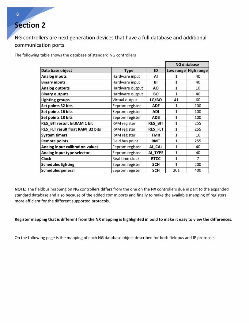
NG controllers are next generation devices that have a full database and additional
communication ports.
The following table shows the database of standard NG controllers
NOTE: The fieldbus mapping on NG controllers differs from the one on the NX controllers due in part to the expanded
standard database and also because of the added comm ports and finally to make the available mapping of registers
more efficient for the different supported protocols.
Register mapping that is different from the NX mapping is highlighted in bold to make it easy to view the differences.
On the following page is the mapping of each NG database object described for both fieldbus and IP protocols.
Data base object Type ID Low range High range
Analog inputs Hardware input AI 1 40
Binary inputs Hardware input BI 1 40
Analog outputs Hardware output AO 1 10
Binary outputs Hardware output BO 1 40
Lighting groups Virtual output LG/BO 41 60
Set points 32 bits Eeprom register ADF 1 100
Set points 16 bits Eeprom register ADI 1 100
Set points 18 bits Eeprom register ADB 1 100
RES_BIT restult bit RAM 1 bit RAM register RES_BIT 1 255
RES_FLT result float RAM 32 bits RAM register RES_FLT 1 255
System timers RAM register TMR 1 16
Remote points Field bus point RMT 1 255
Analog input calibration values Eeprom register AI_CAL 1 40
Analog input type selector Eeprom register AI_TYPE 1 40
Clock Real time clock RTCC 1 7
Schedules lighting Eeprom register SCH 1 200
Schedules general Eeprom register SCH 201 400
NG database

9
NG Hardware analog inputs 1-40
Protocol Default mapping Alternate mapping 1
Optomux AI 1-40
N2-Open AI 1-40
Modbus RTU Input registers 1-40 Holding registers 1-40
Modbus TCP Input registers 101-140 Holding registers 101-140
BACnet MSTP Analog value 1-40
BACnet IP Analog value 1-40
SQL IP/Serial AI 1-40
NG Hardware binary inputs 1-40
Protocol Default mapping Alternate mapping 1 Alternate mapping 2/3
Optomux BI 1-40
N2-Open BI 1-40
Modbus RTU Discrete inputs 101-140 Coils 101-140
Modbus TCP Discrete inputs 101-140 Coils 101-140 input registers 601-640
holding registers 601-640
BACnet MSTP Binary value 101-140
BACnet IP Binary value 1-40
SQL IP/Serial BI 1-40
NG Hardware analog outputs 1-10
Protocol Default mapping Alternate mapping 1
Optomux AO 1-10
N2-Open AO 1-10
Modbus RTU Holding registers 201-210 Input registers 201-210 (read only)
Modbus TCP Holding registers 1-10
BACnet MSTP Analog value 201-210
BACnet IP Analog value 101-110
SQL IP/Serial AO 1-10
NG Hardware binary outputs 1-40 and lighting groups 1-20 (LG map into BO-41-60)
Protocol Default mapping Alternate mapping 1 Alternate mapping 2/3
Optomux BO 1-60
N2-Open BO 1-60
Modbus RTU Coils 301-360 Discrete inputs 301-360 (read only)
Modbus TCP Coils 1-60 Holding registers 701-760 Input registers 701-760 (read only)
Discrete inputs 1-60 (read only)
BACnet MSTP Binary value 301-360
BACnet IP Binary value 101-160
SQL IP/Serial B0 1-60
10
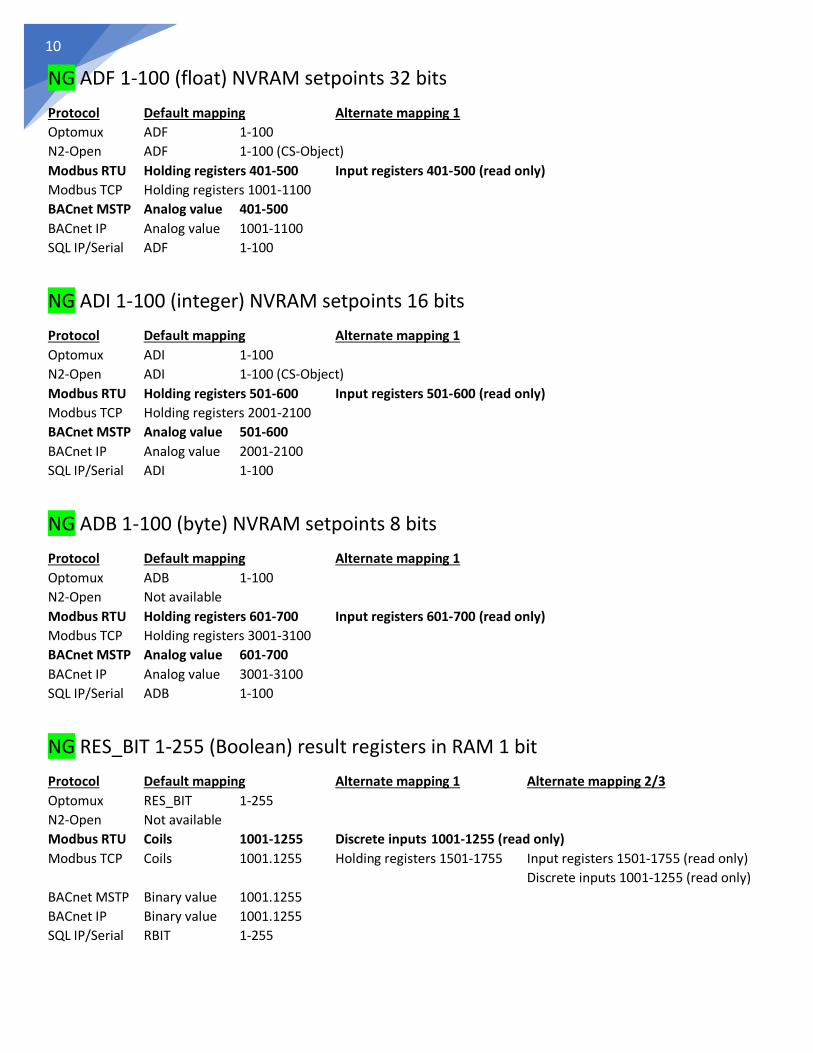
NG ADF 1-100 (float) NVRAM setpoints 32 bits
Protocol Default mapping Alternate mapping 1
Optomux ADF 1-100
N2-Open ADF 1-100 (CS-Object)
Modbus RTU Holding registers 401-500 Input registers 401-500 (read only)
Modbus TCP Holding registers 1001-1100
BACnet MSTP Analog value 401-500
BACnet IP Analog value 1001-1100
SQL IP/Serial ADF 1-100
NG ADI 1-100 (integer) NVRAM setpoints 16 bits
Protocol Default mapping Alternate mapping 1
Optomux ADI 1-100
N2-Open ADI 1-100 (CS-Object)
Modbus RTU Holding registers 501-600 Input registers 501-600 (read only)
Modbus TCP Holding registers 2001-2100
BACnet MSTP Analog value 501-600
BACnet IP Analog value 2001-2100
SQL IP/Serial ADI 1-100
NG ADB 1-100 (byte) NVRAM setpoints 8 bits
Protocol Default mapping Alternate mapping 1
Optomux ADB 1-100
N2-Open Not available
Modbus RTU Holding registers 601-700 Input registers 601-700 (read only)
Modbus TCP Holding registers 3001-3100
BACnet MSTP Analog value 601-700
BACnet IP Analog value 3001-3100
SQL IP/Serial ADB 1-100
NG RES_BIT 1-255 (Boolean) result registers in RAM 1 bit
Protocol Default mapping Alternate mapping 1 Alternate mapping 2/3
Optomux RES_BIT 1-255
N2-Open Not available
Modbus RTU Coils 1001-1255 Discrete inputs 1001-1255 (read only)
Modbus TCP Coils 1001.1255 Holding registers 1501-1755 Input registers 1501-1755 (read only)
Discrete inputs 1001-1255 (read only)
BACnet MSTP Binary value 1001.1255
BACnet IP Binary value 1001.1255
SQL IP/Serial RBIT 1-255

11
NG RES_FLT 1-255 (float) result registers in RAM 32 bit
Protocol Default mapping Alternate mapping 1 Alternate mapping 2
Optomux RES_FLT 1-255 ADF 101-140 (1..40) AI 41-255 (>40)
N2-Open ADF 101-140 AI 41-255
Modbus RTU Holding registers 2001-2255 Input registers 2001-2255 (read only)
Modbus TCP Holding registers 5001-5255
BACnet MSTP Analog value 2001-2255
BACnet IP Analog value 1001.1255
SQL IP/Serial RFLT 1-255
NG Timers 1-16 (integer) in RAM 16 bit
Protocol Default mapping Alternate mapping 1
Optomux TMR 1-16 ADF 101-140
N2-Open ADI 101-116 (CS-Object)
Modbus RTU Holding registers 7001-7016 Input registers 7001-7016 (read only)
Modbus TCP Holding registers 4001-4016
BACnet MSTP Analog value 7001-7016
BACnet IP Analog value 4001-4016
SQL IP/Serial TMR 1-16
NG Remote points (float) in RAM via communication ports 32 bit
Protocol Default mapping Alternate mapping 1 Alternate mapping 2
Optomux RMT 1-255 ADF 181-230 (1..50) AO 51-255 (>50)
N2-Open ADF 181-230 (1..50) AO 51-255 (>50)
Modbus RTU Holding registers 6001-6255 Input registers 6001-6255 (read only)
Modbus TCP Holding registers 6001-6255
BACnet MSTP Analog value 6001-6255
BACnet IP Analog value 6001-6255
SQL IP/Serial RMT 1-255
NG RTCC real time clock and calendar date and time
Protocol Default mapping
Optomux ADF 1-40 (Via remapping with configurator)
N2-Open ADF 1-40 (Via remapping with configurator)
Modbus RTU Holding registers 9001-9010 Modbus and BACnet RTCC mapping is:
Modbus TCP Holding registers 9001-9010 x1 = Year x2 = Month x3 = Day x4 = Weekday
BACnet MSTP Analog value 9001-9010 x5 = Hour x6 = Minutes x7 = Seconds
BACnet IP Analog value 9001-9010
SQL IP/Serial TIME or STATUS queries (read only)

12
NG Lighting schedules 1-100 using 10 contiguous registers (byte) NVRAM
Protocol Default mapping Alternate mapping 1
Optomux Use configurator software Use LCD display
N2-Open Use configurator software Use LCD display
Modbus RTU Not available
Modbus TCP Holding registers 7001-8000 (Maps schedules 1-100)
BACnet MSTP Analog value 7001-8000 (Maps schedules 1-100)
BACnet IP Analog value 7001-8000 (Maps schedules 1-100)
SQL IP/Serial Not available
NG General schedules 201-300 using 10 contiguous registers (byte) NVRAM
Protocol Default mapping Alternate mapping 1
Optomux Use configurator software Use LCD display
N2-Open Use configurator software Use LCD display
Modbus RTU Holding registers 3001-4000 Input registers 3001-4000 (read only)
Modbus TCP Holding registers 8001-9000 (Maps schedules 201-300)
BACnet MSTP Analog value 8001-9000 (Maps schedules 201-300)
BACnet IP Analog value 8001-9000 (Maps schedules 201-300)
SQL IP/Serial Not available
NOTE: See annex one on details how to decode these ten contiguous registers.

13
Section 3
ETH3 controllers are a powerful device that includes the following:
• Web page server with user updatable pages over IP stored on an attached USB memory.
• E-mail server and alarm generator.
• IP gateway for NX/NG controllers attached on the high-speed SPI bus.
• IP gateway for NX/NG controllers attached on any of its two field buses.
• Multiprotocol auto-translator on all communication ports.
• Supports the following industry standard protocols: BACnet, Modbus, Optomux, N2-
Open, SQL over IP as well as on the two field buses as either master or slave, and on IP
as server and soon as client.
• Trending and logging using the attached USB memory.
• Now with updated firmware v3.07 supports a standalone operation controller feature
with its own database and the following features:
o Two PLCs with 400 instructions each.
o 300 NVRAM setpoints.
o 510 result registers for Boolean and math operations.
o 2250 remote point registers over the two field busses and using IP client.
o 400 schedules
o 16 timers
The following table shows the database of the ETH3 and the optionally SPI attached NX/NG controller database
Data base object Type ID Low range High range Low range High range
Analog inputs Hardware input AI 1 40
Binary inputs Hardware input BI 1 40
Analog outputs Hardware output AO 1 40 1 10
Binary outputs Hardware output BO 1 40
Lighting groups Virtual output LG/BO 41 60
Set points 32 bits Eeprom register ADF 1 100 1 100
Set points 16 bits Eeprom register ADI 1 100 1 100
Set points 18 bits Eeprom register ADB 1 100 1 100
RES_BIT restult bit RAM 1 bit RAM register RES_BIT 1 255 1 255
RES_FLT result float RAM 32 bits RAM register RES_FLT 1 255 1 255
System timers RAM register TMR 1 16 1 16
Remote points Field bus point RMT 1 2250 1 255
Analog input calibration values Eeprom register AI_CAL 1 40
Analog input type selector Eeprom register AI_TYPE 1 40
Clock Real time clock RTCC 1 7 1 7
Schedules lighting Eeprom register SCH 1 200 1 200
Schedules general Eeprom register SCH 201 400 201 400
SPI::NX/NG databaseETH3 database

14
NX/NG connected to SPI bus database fieldbus and IP mapping
COM1 and COM2 of the ETH3 as well as the IP port can access both the ETH3 and the SPI::NX/NG attached controllers
databases.
When the ETH3 is used as a gateway for accessing the SPI::NX/NG attached controller database over the IP Ethernet
port for Modbus/TCP or BACnet/IP please refer to the details on sections 1 and 2.
Only the details for accessing the ETH3 database refer to this section.
Scoping mechanism for selecting between the ETH3 and the SPI::NX databases
Since we now have two databases that PLC1+PLC2 on the ETH3 can access, how do we select what we want to access?
This is where scoping comes into play, to simplify things a design decision was made, where all PLC instructions on the
ETH3 can only access the ETH3 local database, outlined on red below which contain:
Local database ETH3
o All the ADF, ADI, ADB, RES_BIT, RES_FLT, TMR registers.
o Remote points from its COM1, COM2 and IP clients
And only the OUTPUT ASSIGN instruction that has been renamed as TRANSFER instruction for this use, can read and
write registers from and to the remote SPI::NX database, shown with the blue dotted arrow below.
EthernetIP
FieldbusCOM1
FieldbusCOM2
SPI bridge
ETH3 controller
NX/NG
The term LOCAL database means that all the registers are on the internal memories of the ETH3 so they can be accessed
quite fast, even the COM1, COM2 and IP client remote points, as once they are polled by their respective masters, the
values of this remote points reside on the ETH3’s memories and can be read or written by the PLC and any other
application or protocol needing them.
Whereas the REMOTE database that comes from the NX/NG is accessed by the SPI bridge, which the PLC must share
with all other protocols and applications using it, and is slower. Therefore a 50 point cache has been added to somehow
relief the pressure put on the SPI bus by the PLC instructions executing faster than the SPI bridge can supply.
Whereas the REMOTE database that comes from the NX/NG is accessed by the SPI bridge, which the PLC must share

15
For this scoping to work seamlessly the software scoping hides the complexities of remapping that happen on the PLC
operands.
On the NX/NG databases the addressing of every individual type is limited to an eight-bit object number, so only
registers from 1 to 255 can be used.
To break this limitation and allow the PLCs of the ETH3 to access more than 255 registers of each type, the internal
addressing for the operands in the ETH for the OUTPUT ASSIGN/TRANSFER instruction has been increased to 11 bits,
thus allowing to map registers in the range from 1 up to 2048.
Below is the linear addressing that the two databases use in the ETH3’s PLC.
So we can see that if a linear addressing were used it would be hard to read by humans, so to help with this the
configurator software uses scoping for both its source and destination operands to help with the translation.
From the table above we can clearly see that all SPI:NX/NG registers are less than 255 and all ETH3 registers are greater
than 1000, so internally everything is clear.
If for example you select that the source operand is the analog input one
When you select OK you will have the instruction write the registers for the OUTPUT ASSIGN/TRANSFER instruction as
shown on the next page.
Data base object Type ID Low range High range Low range High range
Analog inputs Hardware input AI 1 40
Binary inputs Hardware input BI 1 40
Analog outputs Hardware output AO 2001 2040 1 10
Binary outputs Hardware output BO 1 60
Set points 32 bits Eeprom register ADF 1001 1100 1 100
Set points 16 bits Eeprom register ADI 1001 1100 1 100
Set points 18 bits Eeprom register ADB 1001 1100 1 100
RES_BIT restult bit RAM 1 bit RAM register RES_BIT 1001 1255 1 255
RES_FLT result float RAM 32 bits RAM register RES_FLT 1001 1255 1 255
System timers RAM register TMR 1001 1016 1 16
Remote points NX/NG Field bus point RMT 1 255
Remote points COM1 Field bus point AO 1001 2000
Remote points COM2 Field bus point RMT 1001 2000
Remote points IP client IP client point RES_FLT 1501 1750
Clock Real time clock ADI 1201 1210
ETH3 database SPI::NX/NG database
16
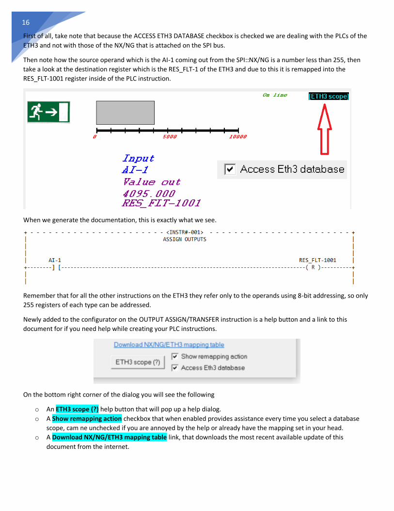
First of all, take note that because the ACCESS ETH3 DATABASE checkbox is checked we are dealing with the PLCs of the
ETH3 and not with those of the NX/NG that is attached on the SPI bus.
Then note how the source operand which is the AI-1 coming out from the SPI::NX/NG is a number less than 255, then
take a look at the destination register which is the RES_FLT-1 of the ETH3 and due to this it is remapped into the
RES_FLT-1001 register inside of the PLC instruction.
When we generate the documentation, this is exactly what we see.
Remember that for all the other instructions on the ETH3 they refer only to the operands using 8-bit addressing, so only
255 registers of each type can be addressed.
Newly added to the configurator on the OUTPUT ASSIGN/TRANSFER instruction is a help button and a link to this
document for if you need help while creating your PLC instructions.
On the bottom right corner of the dialog you will see the following
o An ETH3 scope (?) help button that will pop up a help dialog.
o A Show remapping action checkbox that when enabled provides assistance every time you select a database
scope, cam ne unchecked if you are annoyed by the help or already have the mapping set in your head.
o A Download NX/NG/ETH3 mapping table link, that downloads the most recent available update of this
document from the internet.

17
Pressing the ETH3 scope (?) help button pops-up a dialog that contains an explanation of the scoping of the ETH3
database and a short table showing the relationship of the scoped and un-scoped registers, remember that in the ETH3
PLC only the OUTPUT ASSIGN/TRANSFER instruction uses internally the un-scoped ranges, all other PLC instructions use
the scoped ranges automatically, that is the reason you will not see the scoping field depicted below in all the other PLC
instructions.
From the scoping field shown above on the right, the first option NX DATABASE is not available when you have activated
the ACCESS ETH3 DATABASE checkbox, so only the option for accessing the SPI.NX database and ETH3.XXXX scopes are
available for you.
This can be better explained by an example, here we use an ADD instruction and add three RES-FLT registers 1, 2, 3 and
place the result on RES_FLT-4. As we can see both on the configuration dialog and on the ON-LINE screen because we
have checked the ACCESS ETH3 DATABASE checkbox, ETH3 scope is automatically selected and displayed on the top
right section of the instruction canvas.
18
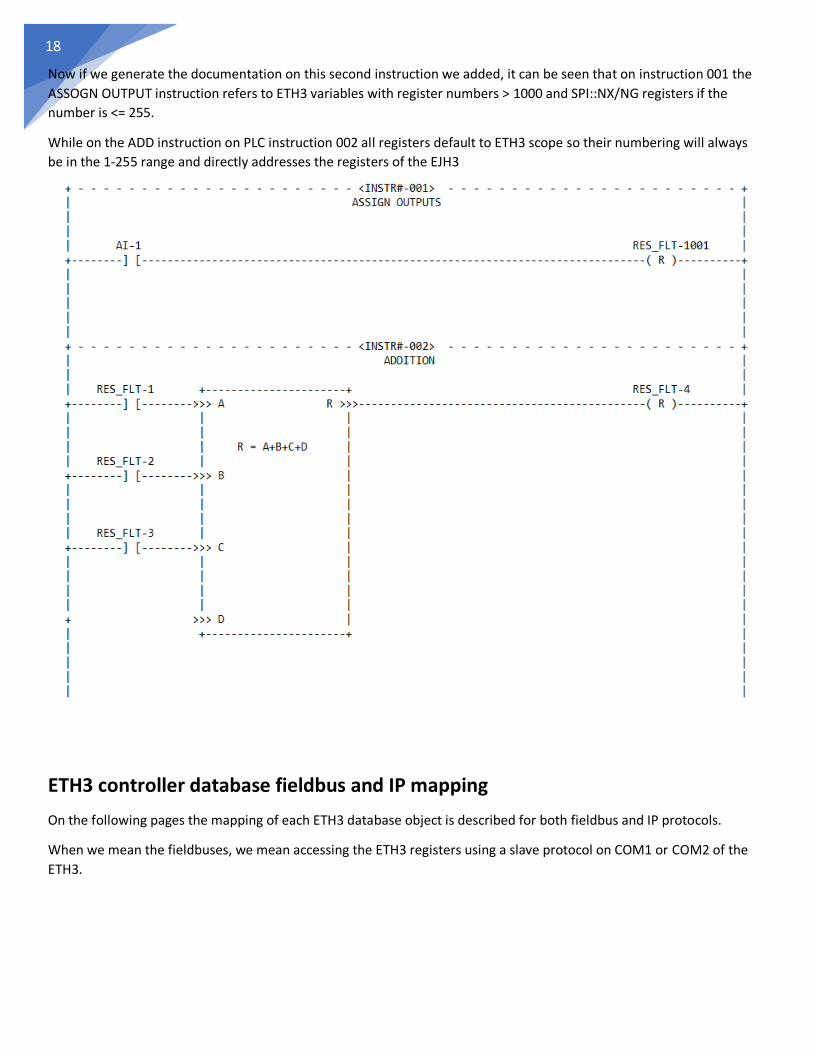
Now if we generate the documentation on this second instruction we added, it can be seen that on instruction 001 the
ASSOGN OUTPUT instruction refers to ETH3 variables with register numbers > 1000 and SPI::NX/NG registers if the
number is <= 255.
While on the ADD instruction on PLC instruction 002 all registers default to ETH3 scope so their numbering will always
be in the 1-255 range and directly addresses the registers of the EJH3
ETH3 controller database fieldbus and IP mapping
On the following pages the mapping of each ETH3 database object is described for both fieldbus and IP protocols.
When we mean the fieldbuses, we mean accessing the ETH3 registers using a slave protocol on COM1 or COM2 of the
ETH3.
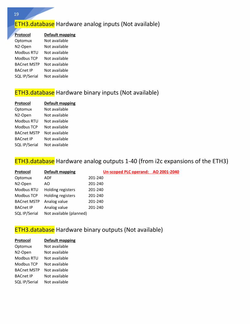
19
ETH3.database Hardware analog inputs (Not available)
Protocol Default mapping
Optomux Not available
N2-Open Not available
Modbus RTU Not available
Modbus TCP Not available
BACnet MSTP Not available
BACnet IP Not available
SQL IP/Serial Not available
ETH3.database Hardware binary inputs (Not available)
Protocol Default mapping
Optomux Not available
N2-Open Not available
Modbus RTU Not available
Modbus TCP Not available
BACnet MSTP Not available
BACnet IP Not available
SQL IP/Serial Not available
ETH3.database Hardware analog outputs 1-40 (from i2c expansions of the ETH3)
Protocol Default mapping Un-scoped PLC operand: AO 2001-2040
Optomux ADF 201-240
N2-Open AO 201-240
Modbus RTU Holding registers 201-240
Modbus TCP Holding registers 201-240
BACnet MSTP Analog value 201-240
BACnet IP Analog value 201-240
SQL IP/Serial Not available (planned)
ETH3.database Hardware binary outputs (Not available)
Protocol Default mapping
Optomux Not available
N2-Open Not available
Modbus RTU Not available
Modbus TCP Not available
BACnet MSTP Not available
BACnet IP Not available
SQL IP/Serial Not available

20
ETH3.database ADF 1-100 (float) NVRAM setpoints 32 bits
Protocol Default mapping Un-scoped PLC operand: ADF 1001-1100
Optomux ADF 1-100
N2-Open ADF 1-100 (CS-Object)
Modbus RTU Holding registers 1101-1200
Modbus TCP Holding registers 1101-1200
BACnet MSTP Analog value 1101-1200
BACnet IP Analog value 1101-1200
SQL IP/Serial Not available (planned)
ETH3.database ADI 1-100 (integer) NVRAM setpoints 16 bits
Protocol Default mapping Un-scoped PLC operand: ADI 1001-1100
Optomux ADI 1-100
N2-Open ADI 1-100 (CS-Object)
Modbus RTU Holding registers 2101-2200
Modbus TCP Holding registers 2101-2200
BACnet MSTP Analog value 2101-2200
BACnet IP Analog value 2101-2200
SQL IP/Serial Not available (planned)
ETH3.database ADB 1-100 (byte) NVRAM setpoints 8 bits
Protocol Default mapping Un-scoped PLC operand: ADB 1001-1100
Optomux ADB 1-100
N2-Open Not available
Modbus RTU Holding registers 3001-3100
Modbus TCP Holding registers 3001-3100
BACnet MSTP Analog value 3001-3100
BACnet IP Analog value 3001-3100
SQL IP/Serial Not available (planned)
ETH3.database RES_BIT 1-255 (Boolean) result registers in RAM 1 bit
Protocol Default mapping Un-scoped PLC operand: RES_BIT 1001-1255
Optomux BO 1-255
N2-Open BO 1-255
Modbus RTU Coils 1601-1855
Modbus TCP Coils 1601-1855
BACnet MSTP Binary value 1601-1855
BACnet IP Binary value 1601-1855
SQL IP/Serial Not available (planned)

21
ETH3.database RES_FLT 1-255 (float) result registers in RAM 32 bit
Un-scoped PLC operand: RES_FLT 1001-1255 Protocol Default mapping Alternate mapping 1
Optomux RES_FLT 1-255 ADF 101-200 (1..100)
N2-Open ADF 101-200
Modbus RTU Holding registers 5501-5755
Modbus TCP Holding registers 5501-5755
BACnet MSTP Analog value 5501-5755
BACnet IP Analog value 5501-5755
SQL IP/Serial Not available (planned)
ETH3.database Timers 1-16 (integer) in RAM 16 bit
Protocol Default mapping Un-scoped PLC operand: TMR 1001-1016
Optomux ADI 101-116
N2-Open ADI 101-116 (CS-Object)
Modbus RTU Holding registers 4101-4116
Modbus TCP Holding registers 4101-4116
BACnet MSTP Analog value 4101-4116
BACnet IP Analog value 4101-4116
SQL IP/Serial Not available (planned)
ETH3.RMT.COM1 Remote points (float) in RAM via communication port 32 bit
Un-scoped PLC operand: AO_1001-2000
Protocol Default mapping Alternate mapping 1
Optomux AO 1-100 (only the first 100 are available on this protocol)
N2-Open AO 1-100 (only the first 100 are available on this protocol)
Modbus RTU Holding registers 12001-13000 6501-7000 (only the first 500 available on alternate mapping)
Modbus TCP Holding registers 12001-13000 6501-7000 (only the first 500 available on alternate mapping)
BACnet MSTP Analog value 12001-13000
BACnet IP Analog value 12001-13000 Alternate Binary value dual mapping added on v3.10.1
SQL IP/Serial Not available (planned)
ETH3.RMT.COM2 Remote points (float) in RAM via communication port 32 bit
Un-scoped PLC operand: RMT_1001-2000
Protocol Default mapping Alternate mapping 1
Optomux AO 101-200 (only the first 100 are available on this protocol)
N2-Open AO 101-200 (only the first 100 are available on this protocol)
Modbus RTU Holding registers 13001-14000 4501-5000 (only the first 500 available on alternate mapping)
Modbus TCP Holding registers 13001-14000 4501-5000 (only the first 500 available on alternate mapping)
BACnet MSTP Analog value 13001-14000
BACnet IP Analog value 13001-14000 Alternate Binary value dual mapping added on v3.10.1
SQL IP/Serial Not available (planned)
22
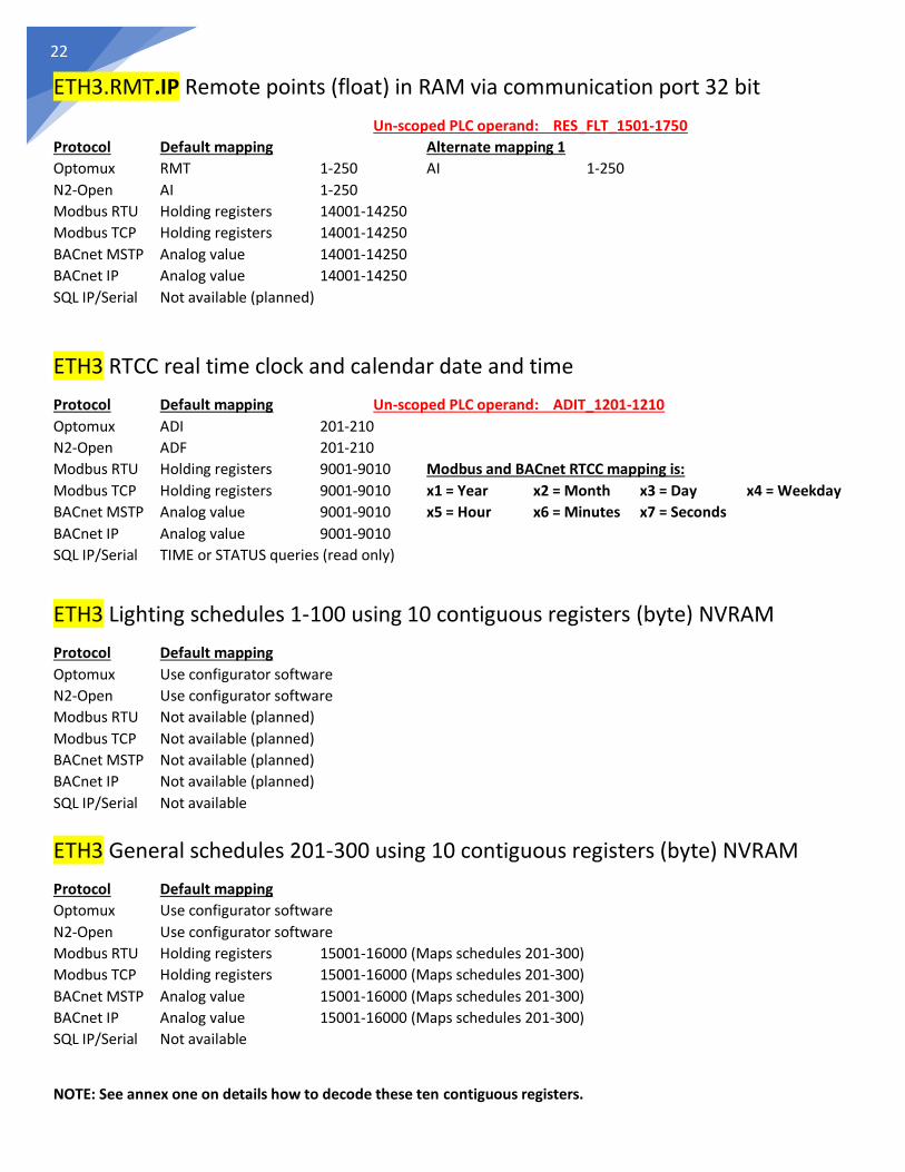
ETH3.RMT.IP Remote points (float) in RAM via communication port 32 bit
Un-scoped PLC operand: RES_FLT_1501-1750
Protocol Default mapping Alternate mapping 1
Optomux RMT 1-250 AI 1-250
N2-Open AI 1-250
Modbus RTU Holding registers 14001-14250
Modbus TCP Holding registers 14001-14250
BACnet MSTP Analog value 14001-14250
BACnet IP Analog value 14001-14250
SQL IP/Serial Not available (planned)
ETH3 RTCC real time clock and calendar date and time
Protocol Default mapping Un-scoped PLC operand: ADIT_1201-1210
Optomux ADI 201-210
N2-Open ADF 201-210
Modbus RTU Holding registers 9001-9010 Modbus and BACnet RTCC mapping is:
Modbus TCP Holding registers 9001-9010 x1 = Year x2 = Month x3 = Day x4 = Weekday
BACnet MSTP Analog value 9001-9010 x5 = Hour x6 = Minutes x7 = Seconds
BACnet IP Analog value 9001-9010
SQL IP/Serial TIME or STATUS queries (read only)
ETH3 Lighting schedules 1-100 using 10 contiguous registers (byte) NVRAM
Protocol Default mapping
Optomux Use configurator software
N2-Open Use configurator software
Modbus RTU Not available (planned)
Modbus TCP Not available (planned)
BACnet MSTP Not available (planned)
BACnet IP Not available (planned)
SQL IP/Serial Not available
ETH3 General schedules 201-300 using 10 contiguous registers (byte) NVRAM
Protocol Default mapping
Optomux Use configurator software
N2-Open Use configurator software
Modbus RTU Holding registers 15001-16000 (Maps schedules 201-300)
Modbus TCP Holding registers 15001-16000 (Maps schedules 201-300)
BACnet MSTP Analog value 15001-16000 (Maps schedules 201-300)
BACnet IP Analog value 15001-16000 (Maps schedules 201-300)
SQL IP/Serial Not available
NOTE: See annex one on details how to decode these ten contiguous registers.

23
Annex 1
When reading or writing schedules, each schedule uses 10 contiguous registers, the following
table gives details on how these ten registers can be decoded to read or write back schedules.
Decoding the 10-byte information example for lighting schedule #1 reading registers 7001-7010
Holding Register # Offset Use Name Description
7001 +0 Configuration bits
Bit_7:
1=Disabled
0=Enabled
Bits_6,5,4 = Schedule type
0 = Command to OFF
1 = Command to ON
2 = Off + Blink (Only lighting schedules)
3 = By period
4 = Set point adjust on schedule (Only general schedules)
Bits_3,2,1,0 = Region
0 = NULL
1 = Analog input (invalid)
2 = Binary input (invalid)
3 = Analog output
4 = Binaty ouptut
5 = Eeprom ADF 32 bits
6 = Eeprom ADI 16 bits
7 = Eeprom ADB 8 bits
8 = RES_BIT
9 = RES_FLOAT
7002 +1 Objects to command
Object number to command:
For lighting schedules:
1 to 20 = RES_BITS-1..20
41 to 60 = Lighting groups
For general schedules:
Object number of the region specified above, i.e.:
Binary outout 1 --or-- ADF-25, etc.
7003 +2 HH start Start hours - 0..23
7004 +3 MM start Start minutes - 0..59
7005 +4 DAY start
If MONTH = 1..12 then this parameter is the day of the month of the start period 1..31
If MONTH= 0, then this parameter is a bit mask to mark days that apply:
Bit_7 = (+128) Holiday
Bit_6 = (+64) Saturday
Bit_5 = (+32 ) Friday
Bit_4 = (+16) Thursday
Bit_3 = (+8) Wednesday
Bit_2 = (+4) Tuesday
Bit_1 = (+2) Monday
Bit_0 = (+1) Sunday
7006 +5 MONTH start0 = Weekly schedule,
1..12 = Monthly schedule (January=1 to December=12)
7007 +6 HH endEnd hour - 0..23
7008 +7 MM endEnd minutes - 0..59
7009 +8 Period type0 = ON on startand OFF at end of period
1 = ON during all of the period
7010 +9 -
General schedule
configuration
Start time
End time
-- or--32 bits
adjust value for
general schedules
24
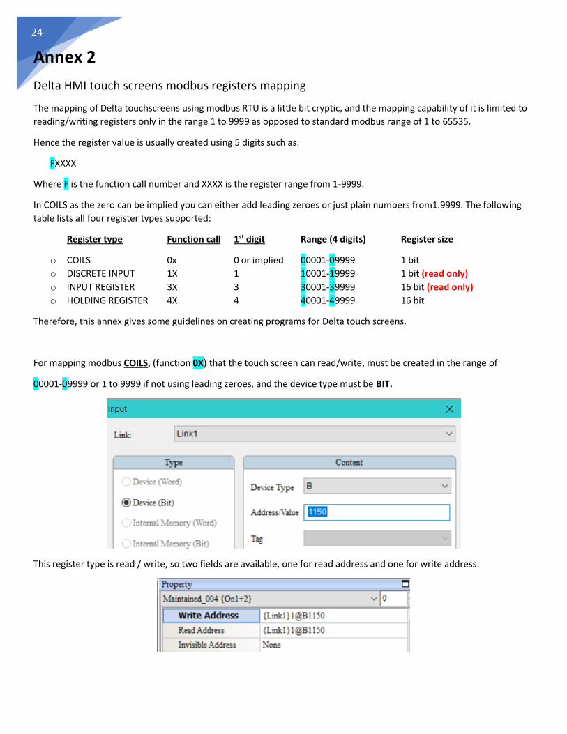
Annex 2
Delta HMI touch screens modbus registers mapping
The mapping of Delta touchscreens using modbus RTU is a little bit cryptic, and the mapping capability of it is limited to
reading/writing registers only in the range 1 to 9999 as opposed to standard modbus range of 1 to 65535.
Hence the register value is usually created using 5 digits such as:
FXXXX
Where F is the function call number and XXXX is the register range from 1-9999.
In COILS as the zero can be implied you can either add leading zeroes or just plain numbers from1.9999. The following
table lists all four register types supported:
Register type Function call 1st digit Range (4 digits) Register size
o COILS 0x 0 or implied 00001-09999 1 bit
o DISCRETE INPUT 1X 1 10001-19999 1 bit (read only)
o INPUT REGISTER 3X 3 30001-39999 16 bit (read only)
o HOLDING REGISTER 4X 4 40001-49999 16 bit
Therefore, this annex gives some guidelines on creating programs for Delta touch screens.
For mapping modbus COILS, (function 0X) that the touch screen can read/write, must be created in the range of
00001-09999 or 1 to 9999 if not using leading zeroes, and the device type must be BIT.
This register type is read / write, so two fields are available, one for read address and one for write address.

25
For mapping modbus DISCRETE INPUTS, (function 1X) that the touch screen can only read, must be created in the range
of 10001-19999 and the device type must be BIT.
This register type is read only, so no write field exists.
For mapping modbus INPUT REGISTERS, (function 3X) that the touch screen can only read, must be created in the range
of 30001-39999 and the device type must be WORD.
This register type is also read only, so no write field exists.
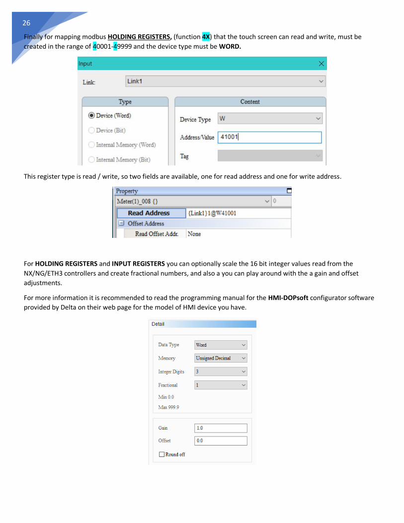
26
Finally for mapping modbus HOLDING REGISTERS, (function 4X) that the touch screen can read and write, must be
created in the range of 40001-49999 and the device type must be WORD.
This register type is read / write, so two fields are available, one for read address and one for write address.
For HOLDING REGISTERS and INPUT REGISTERS you can optionally scale the 16 bit integer values read from the
NX/NG/ETH3 controllers and create fractional numbers, and also a you can play around with the a gain and offset
adjustments.
For more information it is recommended to read the programming manual for the HMI-DOPsoft configurator software
provided by Delta on their web page for the model of HMI device you have.

27
NOTES:
Related Documents