1 LIGO and GEO Developments for Advanced LIGO Sheila Rowan, Stanford University/Univ. of Glasgow on behalf of the LIGO Scientific Collaboration APS Annual Meeting 6th April 2003 G030161-00-R

1 LIGO and GEO Developments for Advanced LIGO Sheila Rowan, Stanford University/Univ. of Glasgow on behalf of the LIGO Scientific Collaboration APS Annual.
Jan 01, 2016
Welcome message from author
This document is posted to help you gain knowledge. Please leave a comment to let me know what you think about it! Share it to your friends and learn new things together.
Transcript
1
LIGO and GEO Developments for Advanced LIGO
Sheila Rowan, Stanford University/Univ. of Glasgow
on behalf of the LIGO Scientific Collaboration
APS Annual Meeting
6th April 2003
G030161-00-R

2
Introduction: LIGO
LIGO interferometers in operation Steady sensitivity improvements throughout commissioning phase -
very close to design goals First science runs carried out, more on the way, (plan for one year of
integrated data at h = 10-21 by end of 2006) Science results currently being prepared for publication, presented at
this meeting
Current sensitivity levels make gravitational wave detection plausible Improved detector sensitivities will let us fully exploit the wealth of
potential gravitational wave sources
Way forward: Advanced LIGO
3
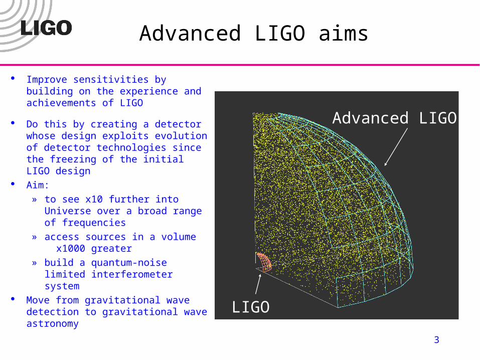
Advanced LIGO aims
Improve sensitivities by building on the experience and achievements of LIGO
Do this by creating a detector whose design exploits evolution of detector technologies since the freezing of the initial LIGO design
Aim:
» to see x10 further into Universe over a broad range of frequencies
» access sources in a volume x1000 greater
» build a quantum-noise limited interferometer system
Move from gravitational wave detection to gravitational wave astronomy
LIGO
Advanced LIGO
4
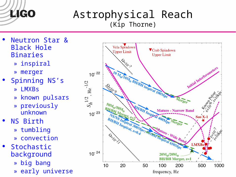
Astrophysical Reach(Kip Thorne)
Neutron Star & Black Hole Binaries» inspiral» merger
Spinning NS’s» LMXBs» known pulsars» previously unknown
NS Birth » tumbling» convection
Stochastic background» big bang» early universe
5
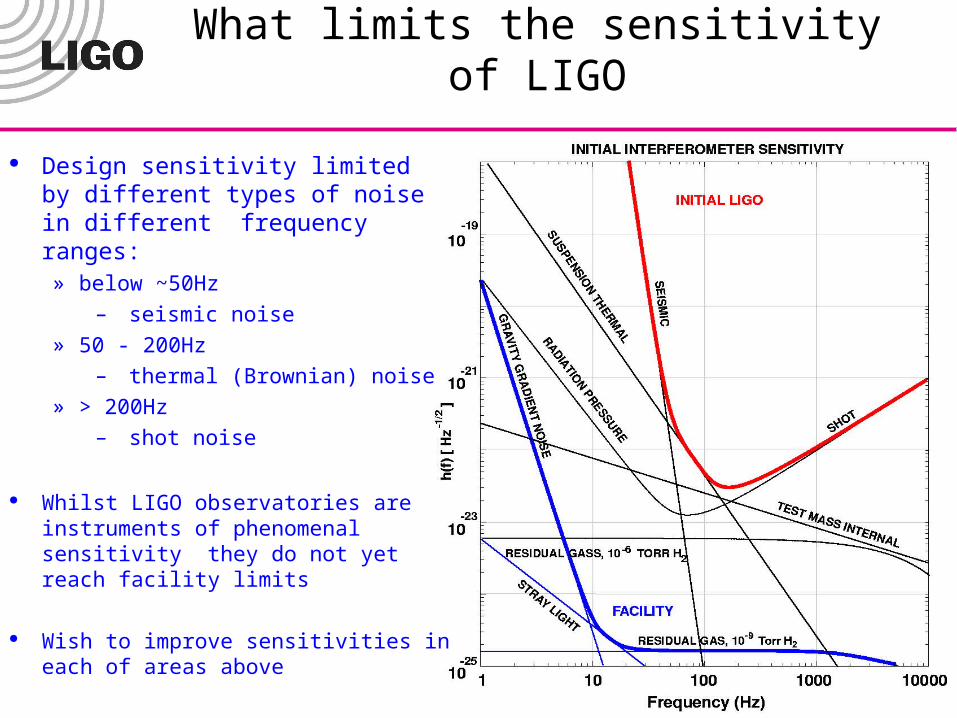
What limits the sensitivity of LIGO
Design sensitivity limited by different types of noise in different frequency ranges:» below ~50Hz
– seismic noise
» 50 - 200Hz
– thermal (Brownian) noise
» > 200Hz
– shot noise
Whilst LIGO observatories are instruments of phenomenal sensitivity they do not yet reach facility limits
Wish to improve sensitivities in each of areas above
6
Advanced LIGO:how to get where we want to go
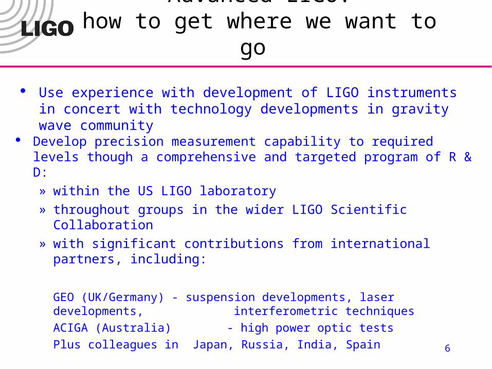
Use experience with development of LIGO instruments in concert with technology developments in gravity wave community
Develop precision measurement capability to required levels though a comprehensive and targeted program of R & D:» within the US LIGO laboratory » throughout groups in the wider LIGO Scientific Collaboration» with significant contributions from international partners, including:
GEO (UK/Germany) - suspension developments, laser developments, interferometric techniques
ACIGA (Australia) - high power optic tests
Plus colleagues in Japan, Russia, India, Spain
7
Advanced LIGO:how to get where we want to go
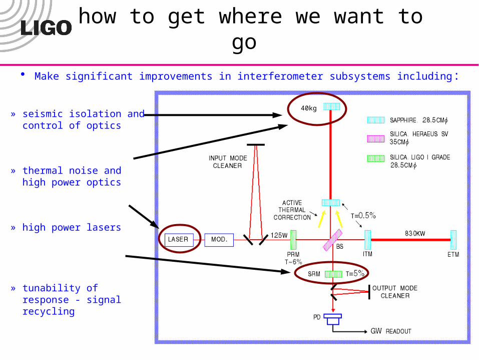
Make significant improvements in interferometer subsystems including:
» seismic isolation and control of optics
» thermal noise and high power optics
» high power lasers
» tunability of response - signal recycling
40kg
8
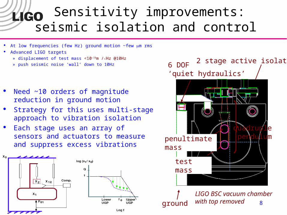
Sensitivity improvements:seismic isolation and control
At low frequencies (few Hz) ground motion ~few m rms Advanced LIGO targets
» displacement of test mass <10-19m /Hz @10Hz» push seismic noise ‘wall’ down to 10Hz
2 stage active isolation6 DOF ‘quiet hydraulics’
ground
test mass
quadruple pendulum
LIGO BSC vacuum chamber with top removed
penultimate mass
Need ~10 orders of magnitude reduction in ground motion
Strategy for this uses multi-stage approach to vibration isolation
Each stage uses an array of sensors and actuators to measure and suppress excess vibrations
9
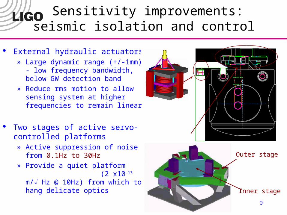
Sensitivity improvements:seismic isolation and control
External hydraulic actuators» Large dynamic range (+/-1mm) - low
frequency bandwidth, below GW detection band
» Reduce rms motion to allow sensing system at higher frequencies to remain linear
Two stages of active servo-controlled platforms» Active suppression of noise from
0.1Hz to 30Hz
» Provide a quiet platform (2 x10-13 m/ Hz @ 10Hz) from which to hang delicate optics
Inner stage
Outer stage
10
Sensitivity improvements:seismic isolation and control
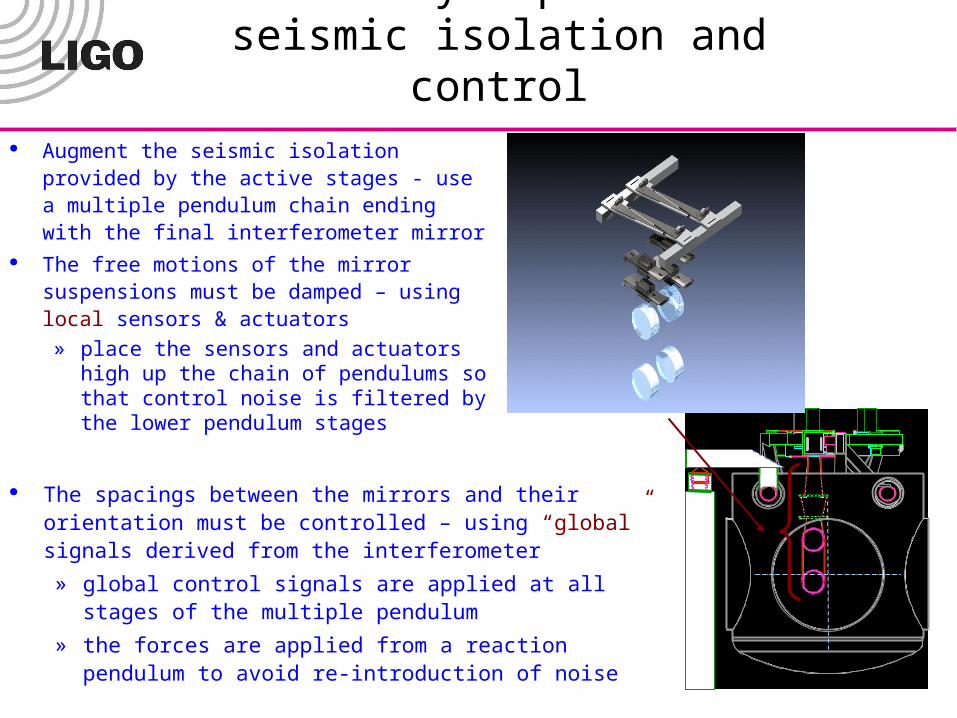
Augment the seismic isolation provided by the active stages - use a multiple pendulum chain ending with the final interferometer mirror
The free motions of the mirror suspensions must be damped – using local sensors & actuators
» place the sensors and actuators high up the chain of pendulums so that control noise is filtered by the lower pendulum stages
The spacings between the mirrors and their orientation must be controlled – using “global” signals derived from the interferometer
» global control signals are applied at all stages of the multiple pendulum
» the forces are applied from a reaction pendulum to avoid re-introduction of noise
11
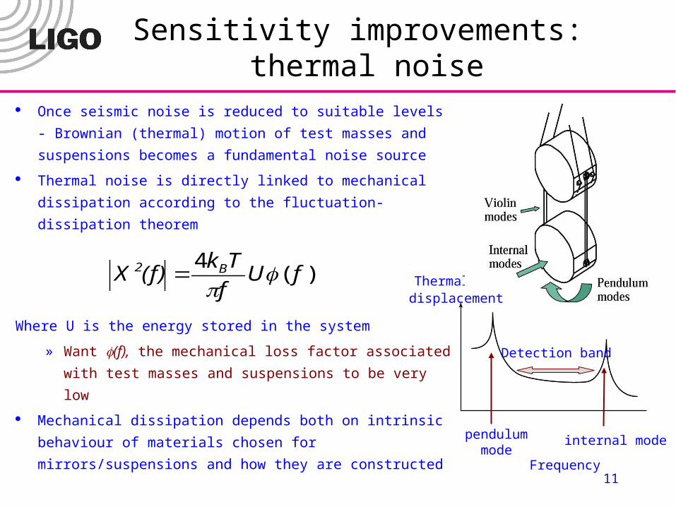
Once seismic noise is reduced to suitable levels -
Brownian (thermal) motion of test masses and
suspensions becomes a fundamental noise source
Thermal noise is directly linked to mechanical dissipation
according to the fluctuation-dissipation theorem
Where U is the energy stored in the system
» Want (f), the mechanical loss factor associated with
test masses and suspensions to be very low
Mechanical dissipation depends both on intrinsic
behaviour of materials chosen for mirrors/suspensions
and how they are constructed
)(4
fUf
Tk(f)X B2
Sensitivity improvements: thermal noise
pendulummode
internal mode
Frequency
Thermal
Detection band
displacement

12
Sensitivity improvements: thermal noise
600m long German-UK GEO interferometer currently using triple-suspension systems with quasi-monolithic final stages for all main optics (installed Dec 02)
Fused silica test masses bonded to silica suspension fibers
Ultra-low mechanical loss suspensions at the heart of the interferometer
13
Sensitivity improvements: thermal noise
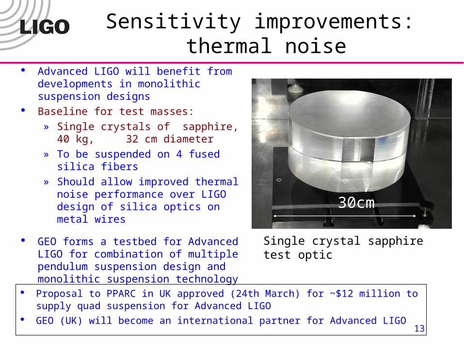
Advanced LIGO will benefit from developments in monolithic suspension designs
Baseline for test masses:
» Single crystals of sapphire, 40 kg, 32 cm diameter
» To be suspended on 4 fused silica fibers
» Should allow improved thermal noise performance over LIGO design of silica optics on metal wires
GEO forms a testbed for Advanced LIGO for combination of multiple pendulum suspension design and monolithic suspension technology
Proposal to PPARC in UK approved (24th March) for ~$12 million to supply quad suspension for Advanced LIGO
GEO (UK) will become an international partner for Advanced LIGO
30cm
Single crystal sapphire test optic

14
Sensitivity improvements:laser developments
At high frequencies shot noise - counting statistics of photons - sets limit to sensitivity
» Improves with P laser
LIGO laser = 10W Advanced LIGO = 180W LSC collaboration to develop laser source led by GEO (Germany) group - LIGO lab sets
requirements, interfaces Design: injection locked YAG with 20 W Master Oscillator
85W demonstrated, design in place for > 200 W laser
Maike Frede, LSC talk, March 03
f
f2 f
Q R
f
f
HR@ 1064HT@ 808
YAG / Nd:YAG / YAG3x 7x40x7
f Q R f
FIE O M
N P R O
20 W M aster
B P
H igh Pow er S lave
FI
m odem ach ing optics
YAG / Nd:YAG3x2x6
output
Proposal to BMBF to be submitted by GEO (Germany) this year for capital contribution to Adv. LIGO (same level as UK contribution) - used to provide the pre-stabilized lasers
Would allow GEO (Germany) to become an international partner for Advanced LIGO
15
LIGO
Advanced LIGOS
eismic
Suspension
thermal
Test mass thermalQ
uantum
Sensitivity improvements:high power optics
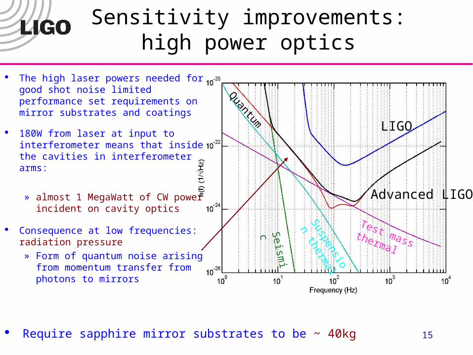
The high laser powers needed for good shot noise limited performance set requirements on mirror substrates and coatings
180W from laser at input to interferometer means that inside the cavities in interferometer arms:
» almost 1 MegaWatt of CW power incident on cavity optics
Consequence at low frequencies: radiation pressure» Form of quantum noise arising
from momentum transfer from photons to mirrors
Require sapphire mirror substrates to be ~ 40kg
16
Sensitivity improvements:high power optics
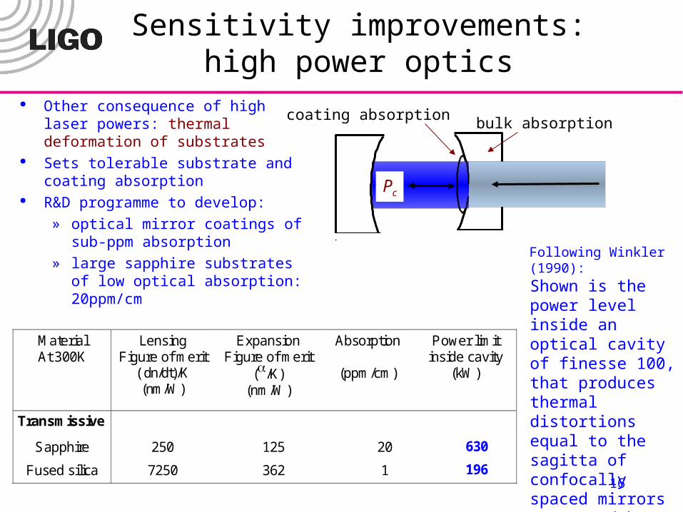
Other consequence of high laser powers: thermal deformation of substrates
Sets tolerable substrate and coating absorption
R&D programme to develop:
» optical mirror coatings of sub-ppm absorption
» large sapphire substrates of low optical absorption: 20ppm/cm
MaterialAt 300K
LensingFigure of merit
( dn/dt)/K(nm/W)
ExpansionFigure of merit
(/K)(nm/W)
Absorption
(ppm/cm)
Power limitinside cavity
(kW)
Transmissive
Sapphire 250 125 20 630
Fused silica 7250 362 1 196
Shown is the power level inside an optical cavity of finesse 100, that produces thermal distortions equal to the sagitta of confocally spaced mirrors separated by 4 km. A coating absorption of 1ppm is assumed.
Following Winkler (1990):
Pc
coating absorptionbulk absorption

17
Sensitivity improvements:high power optics
To deal with thermal effects, technology has been developed to allow active control of lensing and figure of optics in situ
Adaptive thermal compensation schemes can correct for axisymmetric thermal distortions
Suspended heating element used to radiatively heat optic
Figures show measured wavefront
distortion of a probe laser beam without and with thermal compensation
Technology successfully adopted by GEO to correct for mismatches in radius of curvature of mirrors in interferometer arms
R. LawrenceMIT
18
Sensitivity improvements:high power optics
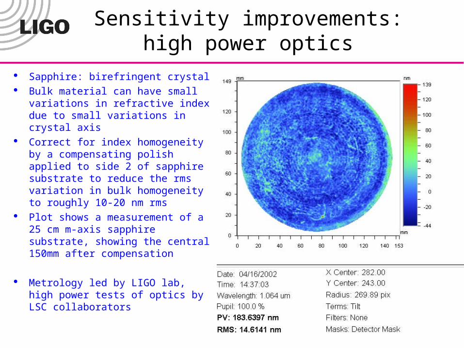
Sapphire: birefringent crystal Bulk material can have small
variations in refractive index due to small variations in crystal axis
Correct for index homogeneity by a compensating polish applied to side 2 of sapphire substrate to reduce the rms variation in bulk homogeneity to roughly 10-20 nm rms
Plot shows a measurement of a 25 cm m-axis sapphire substrate, showing the central 150mm after compensation
Metrology led by LIGO lab, high power tests of optics by LSC collaborators
19
Sensitivity improvements:signal recycling
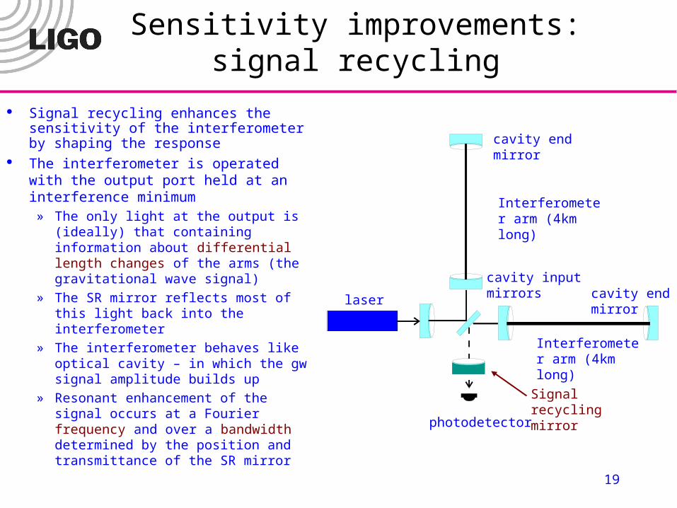
Signal recycling enhances the sensitivity of the interferometer by shaping the response
The interferometer is operated with the output port held at an interference minimum
» The only light at the output is (ideally) that containing information about differential length changes of the arms (the gravitational wave signal)
» The SR mirror reflects most of this light back into the interferometer
» The interferometer behaves like optical cavity – in which the gw signal amplitude builds up
» Resonant enhancement of the signal occurs at a Fourier frequency and over a bandwidth determined by the position and transmittance of the SR mirror
cavity end mirror
Interferometer arm (4km long)
cavity end mirror
Interferometer arm (4km long)
photodetector
Signal recycling mirror
cavity input mirrorslaser
20
Sensitivity improvements:signal recycling
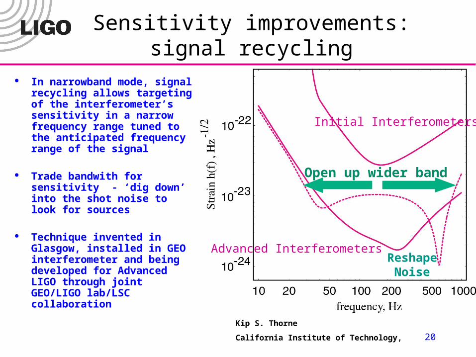
Initial Interferometers
Advanced Interferometers
Open up wider band
ReshapeNoise
Kip S. Thorne
California Institute of Technology,
In narrowband mode, signal recycling allows targeting of the interferometer’s sensitivity in a narrow frequency range tuned to the anticipated frequency range of the signal
Trade bandwith for sensitivity - ‘dig down’ into the shot noise to look for sources
Technique invented in Glasgow, installed in GEO interferometer and being developed for Advanced LIGO through joint GEO/LIGO lab/LSC collaboration
21
LIGO
Advanced LIGOS
eismic
Suspension
thermal
Test mass thermalQ
uantum
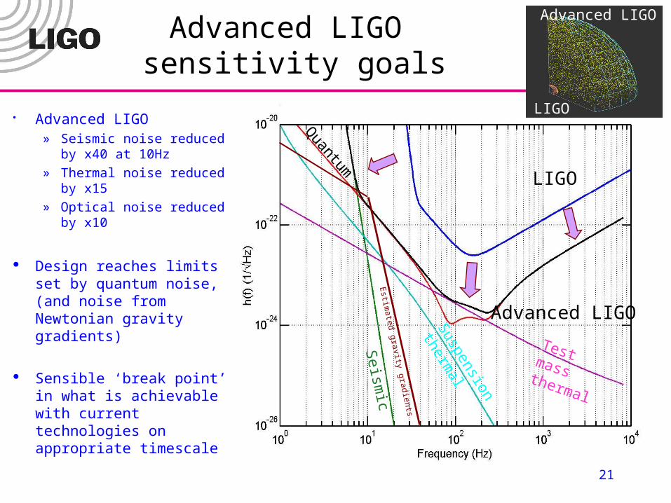
Advanced LIGO sensitivity goals
LIGO
Advanced LIGO
Advanced LIGO» Seismic noise reduced
by x40 at 10Hz» Thermal noise reduced
by x15» Optical noise reduced
by x10
Design reaches limits set by quantum noise, (and noise from Newtonian gravity gradients)
Sensible ‘break point’ in what is achievable with current technologies on appropriate timescale
Estim
ated gravity gradients

22
The Advanced LIGO Collaboration
Development throughout the LIGO Scientific Collaboration (LSC)» International support and significant material participation» Particularly strong collaboration with German-UK GEO group, capital partnership
Advanced LIGO design, R&D, and fabrication spread among the LSC» LIGO Laboratory leads, coordinates, takes responsibility for Observatories
Continuing strong support from the NSF at all levels – theory, R&D, operation of the Laboratory
Forms part of the international network of current and planned detectors:» VIRGO (Italy-France), GEO-600 (Germany-UK), TAMA (Japan), ACIGA
(Australia)
Complementary to planned space-based experiment LISA - targeted at sources <<10Hz
23
Timeline
Initial LIGO Observation 2002 – 2006» 1+ year observation within LIGO Observatory» Significant observation in coincidence with international detector network, GEO, LIGO,
TAMA Targeted R&D program to develop technologies 1998 - 2005
» Baseline design developed by LSC in 1998» R&D continues to refine Final Design, 2005
Advanced LIGO proposal status» PPARC (UK) proposal for capital contribution submitted June 2002, approved
March 2003» NSF construction proposal submitted Feb 2003 for fabrication, installation.
Currently under review» ARC (Australia) proposal for capital contribution to be submitted in May 2003» BMBF (Germany) proposal for capital contribution to be submitted later in 2003
Start installation in 2007» Baseline is a staged installation, Livingston and then Hanford Observatories
Start coincident observations in 2009
24
Summary
LIGO detectors are in operation» First science run completed, second run currently underway» First publications are in preparation» Discoveries plausible
Evolution to Advanced LIGO » Develop advanced detectors that approach and exploit the
facility limits on interferometer performance
» R&D and prototyping well underway
» Challenging astrophysics promised
Related Documents


