1. Introduction The term Rapid Prototyping or Additive Manufacturing (AM) is used in a variety of industries to describe a process which rapidly creates the representation of a system or part prior to final release or commercialisation. Additive manufacturing is a layer-based automated fabrication process for making scaled three-dimensional physical objects directly from 3D-CAD data, without using part-dependent tools. It was originally called 3D printing, and this term is still frequently used, however other terms used in this technology include additive layer manufacturing, rapid prototyping, and direct manufacturing [1]. There are several types of 3D printers used, but all involve the same basic approach for ‘printing’ an object: spraying or otherwise transferring a substance in multiple layers onto a building surface, beginning with the bottom layer. This technology’s initial focus on polymers and photopolymers was later supplemented by ceramics, metals, and composites. This paper presents the most widely-used rapid prototyping technologies and the materials which can be used. The most popular are thermoplastics, photopolymers, plastic powders for Selective Laser Sintering (SLS) methods, and metal powders for Direct Metal Laser Sintering (DMLS), Electron Beam Melting (EBM) or Selective Laser Melting (SLM) methods. Some printing methods use a composite starting material, e.g. cellulose- gypsum powder, a binder, and a filling for 3DP, or Laminated Object Modelling (LOM) films of paper or plastic and adhesive, but most methods use homogeneous materials. However, in recent years, some attempts have been made to introduce new methods and materials enabling the use of spatial composites. Advances in rapid prototyping materials include improvements of properties, such as: tear and thermal resistance, shape memory, stiffness, photorealistic colour, and biocompability [2]. 2. Stereolithography (SLA) SLA uses photopolimerisation and is not only the oldest but remains the most complex AM process. An SLA machine consists of a build chamber filled with the liquid build material and a laser scanner unit, generating the x-y contour (horizontal build plane), mounted on top of it. The build chamber is equipped with a build platform which can be moved in the build (z) direction. The laser beam simultaneously performs the contouring and solidification of each layer as well as its bonding to the preceding layer. The motion of the beam is controlled by the slice data of each layer and directed by the laser scanner. Following solidification of one layer, the build platform, including the partially finished part, is lowered by distance equivalent to the thickness of one layer and a new layer of resin is applied using the recoater. The process continues until the part is finished (Fig. 1). This technology requires support. Fig. 1. The stereolithography (SLA) method Arch. Metall. Mater., Vol. 61 (2016), No 2, p. 891–896 DOI: 10.1515/amm-2016-0151 P. DUDEK* ,# , A. RAPACZ-KMITA** RAPID PROTOTYPING: TECHNOLOGIES, MATERIALS AND ADVANCES In the context of product development, the term rapid prototyping (RP) is widely used to describe technologies which create physical prototypes directly from digital data. Recently, this technology has become one of the fastest-growing methods of manufacturing parts. The paper provides brief notes on the creation of composites using RP methods, such as stereolithography, selective laser sintering or melting, laminated object modelling, fused deposition modelling or three- dimensional printing. The emphasis of this work is on the methodology of composite fabrication and the variety of materials used in these technologies. Keywords: Rapid prototyping, Additive manufacturing, Composites * AGH UNIVERSITY OF SCIENCE AND TECHNOLOGY, FACULTY OF MECHANICAL ENGINEERING AND ROBOTICS, AL. MICKIEWICZA 30, 30-059 KRAKÓW, POLAND ** AGH UNIVERSITY OF SCIENCE AND TECHNOLOGY, FACULTY OF MATERIALS SCIENCE AND CERAMICS, , AL. MICKIEWICZA 30, 30-059 KRAKÓW, POLAND # Corresponding author: [email protected]

Welcome message from author
This document is posted to help you gain knowledge. Please leave a comment to let me know what you think about it! Share it to your friends and learn new things together.
Transcript
1. Introduction
The term Rapid Prototyping or Additive Manufacturing (AM) is used in a variety of industries to describe a process which rapidly creates the representation of a system or part prior to final release or commercialisation. Additive manufacturing is a layer-based automated fabrication process for making scaled three-dimensional physical objects directly from 3D-CAD data, without using part-dependent tools. It was originally called 3D printing, and this term is still frequently used, however other terms used in this technology include additive layer manufacturing, rapid prototyping, and direct manufacturing [1].
There are several types of 3D printers used, but all involve the same basic approach for ‘printing’ an object: spraying or otherwise transferring a substance in multiple layers onto a building surface, beginning with the bottom layer. This technology’s initial focus on polymers and photopolymers was later supplemented by ceramics, metals, and composites.
This paper presents the most widely-used rapid prototyping technologies and the materials which can be used. The most popular are thermoplastics, photopolymers, plastic powders for Selective Laser Sintering (SLS) methods, and metal powders for Direct Metal Laser Sintering (DMLS), Electron Beam Melting (EBM) or Selective Laser Melting (SLM) methods. Some printing methods use a composite starting material, e.g. cellulose-gypsum powder, a binder, and a filling for 3DP, or Laminated Object Modelling (LOM) films of paper or plastic and adhesive, but most methods use homogeneous materials. However, in recent years, some attempts have been made to introduce new methods and materials enabling the use of spatial composites. Advances in rapid prototyping materials include improvements of properties, such as: tear and thermal resistance, shape memory, stiffness, photorealistic colour, and biocompability [2].
2. Stereolithography (SLA)
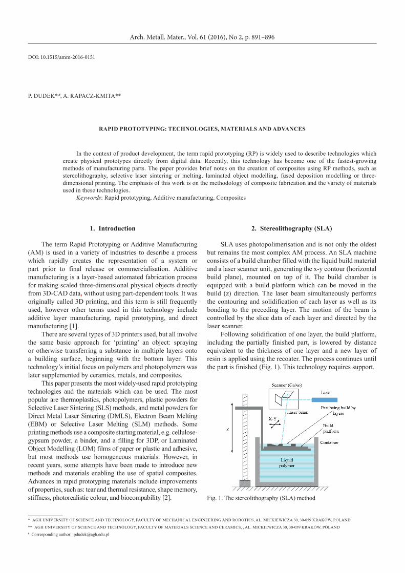
SLA uses photopolimerisation and is not only the oldest but remains the most complex AM process. An SLA machine consists of a build chamber filled with the liquid build material and a laser scanner unit, generating the x-y contour (horizontal build plane), mounted on top of it. The build chamber is equipped with a build platform which can be moved in the build (z) direction. The laser beam simultaneously performs the contouring and solidification of each layer as well as its bonding to the preceding layer. The motion of the beam is controlled by the slice data of each layer and directed by the laser scanner.
Following solidification of one layer, the build platform, including the partially finished part, is lowered by distance equivalent to the thickness of one layer and a new layer of resin is applied using the recoater. The process continues until the part is finished (Fig. 1). This technology requires support.
Fig. 1. The stereolithography (SLA) method
Arch. Metall. Mater., Vol. 61 (2016), No 2, p. 891–896
DOI: 10.1515/amm-2016-0151
P. DuDEk*,#, A. RAPACz-kMITA**
RApId pRototypIng: technoLogIeS, mAteRIALS And AdvAnceS
In the context of product development, the term rapid prototyping (RP) is widely used to describe technologies which create physical prototypes directly from digital data. Recently, this technology has become one of the fastest-growing methods of manufacturing parts. The paper provides brief notes on the creation of composites using RP methods, such as stereolithography, selective laser sintering or melting, laminated object modelling, fused deposition modelling or three-dimensional printing. The emphasis of this work is on the methodology of composite fabrication and the variety of materials used in these technologies.
Keywords: Rapid prototyping, Additive manufacturing, Composites
* AGH unIvERSITy OF SCIEnCE AnD TECHnOLOGy, FACuLTy OF MECHAnICAL EnGInEERInG AnD ROBOTICS, AL. MICkIEwICzA 30, 30-059 kRAków, POLAnD
** AGH unIvERSITy OF SCIEnCE AnD TECHnOLOGy, FACuLTy OF MATERIALS SCIEnCE AnD CERAMICS, , AL. MICkIEwICzA 30, 30-059 kRAków, POLAnD# Corresponding author: [email protected]
892
One variant of the photo polymerisation process is the use of a Digital Light Processing (DLP) projector as a uv light source, which projects the complete contour of a cross section of the actual layer and simultaneously initiates solidification.
In order to produce composites using SLA methods, a photopolymer is mixed with particles or fibres that enhance the physical or mechanical properties of the manufactured parts. unfortunately, the addition of the reinforcement leads to problems – primarily related to the viscosity of the photopolymer, which lead in turn to problems in applying a new layer of material [3].
In addition, there may occur other inconveniences – such as poor homogeneity of the particles in the resin; the formation of air bubbles which subsequently form pores, thereby prolonging the cure time; the need to increase the laser power or the cure time, and other requirements that must be met to ensure the uniformity of the shape or size of the particles [4]. Resin can be reinforced by continuous long or short fibres, but it should be kept in mind that fibres also settle in uncured regions, which leads to problems with post-processing of the final part [5, 6].
Some of these problems can be solved by e.g. appropriate types of monomers, different methods of applying a new layer, increased laser power, or a surface coating which reduces the viscosity of the particles or fibres. Additionally, fibres may lose the opacity of build material to uv light, which creates a problem with proper curing of the resin. It must be mentioned that in existing techniques, powder filling reinforcement is used exclusively for creating ceramic parts.
Some commercially-produced machines use this technology to offer the option of using composite build materials, for example CeraFab 7500 [7], which enable the use of ceramic powder with uv-curable resins. Following the production of parts, the resin can be burned out of the ceramics. This procedure enables the production of parts which are very complicated in shape, but porous as well as limited in size and material.
3. Laminated object manufacturing (Lom)
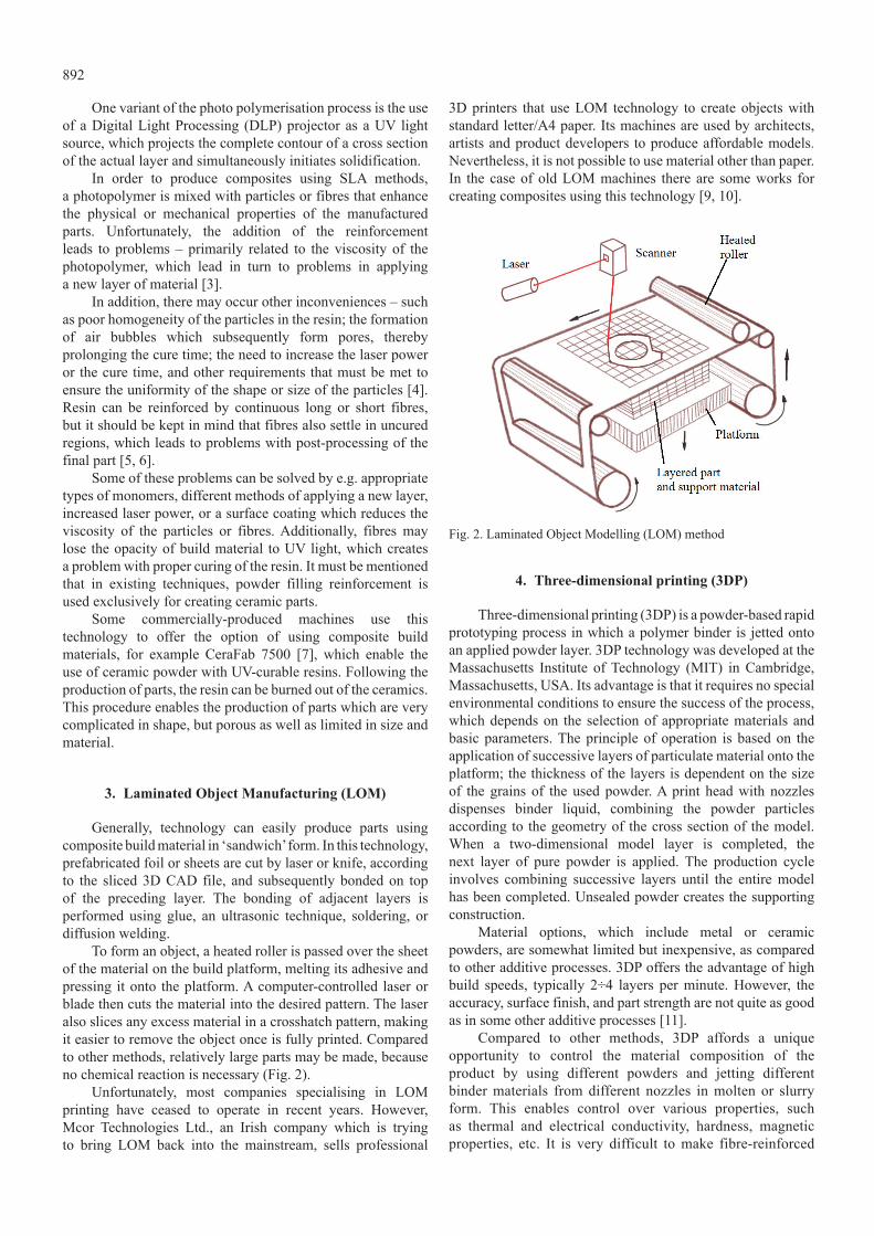
Generally, technology can easily produce parts using composite build material in ‘sandwich’ form. In this technology, prefabricated foil or sheets are cut by laser or knife, according to the sliced 3D CAD file, and subsequently bonded on top of the preceding layer. The bonding of adjacent layers is performed using glue, an ultrasonic technique, soldering, or diffusion welding.
To form an object, a heated roller is passed over the sheet of the material on the build platform, melting its adhesive and pressing it onto the platform. A computer-controlled laser or blade then cuts the material into the desired pattern. The laser also slices any excess material in a crosshatch pattern, making it easier to remove the object once is fully printed. Compared to other methods, relatively large parts may be made, because no chemical reaction is necessary (Fig. 2).
unfortunately, most companies specialising in LOM printing have ceased to operate in recent years. However, Mcor Technologies Ltd., an Irish company which is trying to bring LOM back into the mainstream, sells professional
3D printers that use LOM technology to create objects with standard letter/A4 paper. Its machines are used by architects, artists and product developers to produce affordable models. nevertheless, it is not possible to use material other than paper. In the case of old LOM machines there are some works for creating composites using this technology [9, 10].
Fig. 2. Laminated Object Modelling (LOM) method
4. three-dimensional printing (3dp)
Three-dimensional printing (3DP) is a powder-based rapid prototyping process in which a polymer binder is jetted onto an applied powder layer. 3DP technology was developed at the Massachusetts Institute of Technology (MIT) in Cambridge, Massachusetts, uSA. Its advantage is that it requires no special environmental conditions to ensure the success of the process, which depends on the selection of appropriate materials and basic parameters. The principle of operation is based on the application of successive layers of particulate material onto the platform; the thickness of the layers is dependent on the size of the grains of the used powder. A print head with nozzles dispenses binder liquid, combining the powder particles according to the geometry of the cross section of the model. when a two-dimensional model layer is completed, the next layer of pure powder is applied. The production cycle involves combining successive layers until the entire model has been completed. unsealed powder creates the supporting construction.
Material options, which include metal or ceramic powders, are somewhat limited but inexpensive, as compared to other additive processes. 3DP offers the advantage of high build speeds, typically 2÷4 layers per minute. However, the accuracy, surface finish, and part strength are not quite as good as in some other additive processes [11].
Compared to other methods, 3DP affords a unique opportunity to control the material composition of the product by using different powders and jetting different binder materials from different nozzles in molten or slurry form. This enables control over various properties, such as thermal and electrical conductivity, hardness, magnetic properties, etc. It is very difficult to make fibre-reinforced

893
composite using a powder-fibre mixture or jetting the fibre, but it is possible to infiltrate a porous preform of ceramics or metal obtained by 3DP with a metal or alloy to make the composite [12-14].
5. Fused deposition modelling (Fdm)
Fused deposition modelling (FDM) is one of the best-known methods of rapid prototyping. A thermoplastic filament is unwound from a coil and material is supplied to an extrusion nozzle. The nozzle is heated to the melting point of the plastic and includes a mechanism which enables the flow of melted plastic to be stopped or continued. The nozzle is assembled to a mechanical head which can be moved over the table, according to the required slice geometry. It deposits a thin bead of extruded plastic to form each subsequent layer. The plastic hardens immediately after being extruded from the nozzle and bonds to the layer below.
z
Building platform
Part
Support
Build material
Support material
Printing head with extrusion nozzles
Fig. 3. Fused Deposition Modelling method
After finishing a layer, the platform holding the part moves vertically in the z direction to begin depositing a new layer on top of the previous one. The process is similar to building a model with a very small hot-glue gun (Fig. 3).
The production system is equipped with a second nozzle in the head that in parallel extrudes support material for building prop for any structure with an overhang angle less than 45° from horizontal as a default. The support materials can be later broken away or dissolved.
Developed by Stratasys Ltd., FDM machines can fabricate parts in a relatively wide range of pure materials including elastomers, ABS (acrylonitrile butadiene styrene), polycarbonate (PC), nylon PA12, PPSF/PPSu, uLTEM 1010, uLTEM 9085, or mixed materials such as PC-ABS.
Additionally, home or semi-professional users can use many other materials created by specialised companies or users, including also composite materials. Many papers presenting various composite materials, including biomaterials, have been published [15,16,17]. Due to their very porous internal structure, provided by the process, it is possible to infiltrate manufactured parts with epoxy resin for sealing parts or to make it stronger but heavier [18].
6. Selective laser sintering or melting (SLS/SLm)
Selective laser sintering or melting (SLS/SLM) is one of the most frequently used additive technologies to produce functionally graded parts for aerospace, automotive, art/architecture or medical applications. This process enables manufacturing of complex 3D parts through consolidating successive layers of powder material on top of another one. A laser beam is used as the heating source to locally heat and sinter the deposited powder layer according to predetermined geometries. The sequence of powder deposition and laser scanning is repeated until the 3D part is completed (Fig. 4).
Fig. 4. The selective laser sintering (SLS) process
The primary benefits of SLS are durability the produced parts and the opportunity for SLS users to choose from the wide range of engineering-grade materials, available in the RP industry. Furthermore, SLS does not require support structures during the forming process, as the unused powdered material that surrounds the part provides adequate support. The main disadvantages of SLS are relatively low accuracy/repeatability, poor surface finish, and comparatively high porosity of the fabricated elements.
using SLS process, it is possible to produce Polymer Matrix Composites by mixed ceramic and polymer powders sintered together [19]. The best results are achieved using coated powders, where cores of the powders are derived from metal or ceramics, while the coatings are polymers. Some types of these powders are commercially available: Al-filled polyamide (EOS Alumide), glass-filled polyamide (EOS PA 3200 GF), carbon fibre filled polyamide, however the addition of carbon fibers creates problems with obtaining sharp edges.
There are also some papers describing the creation of composites using coated powders: hydroxyapatite-filled HDPE (High-density polyethylene) or PA (Polyamide), (Tricalcium phosphate) TCP-glass powder, mixed uncoated ceramics with polymers, and uncoated ceramic powder with polymer mixtures [20, 21].
using the SLS or SLM methods, it is possible to create also Metal Matrix Composite or Ceramic Matrix Composites. In order to achieve full density of the produced parts structure, either extra material must be added to the powder mixture or the porous green body product must be infiltrated [22-24].
In the Department of Manufacturing Systems of the university of Science and Technology in Cracow, studies

894
were also done to test the potential for the production of reinforcement parts using the SLS method. First, tests were done with polyamide powder mixed with Al2O3 powder in a weight proportion of 75% PA2200 to 25% Al2O3. The laser scanning parameters were exactly the same as for pure PA2200: 1500 mm/s scan speed, 16w of power for the core, contour, up- and down-skin, working chamber temperature set at 172°C, pre-heating time of 180 min. After printing and cooling time, the printed parts were cleaned in a sand cabinet. Due to a little warping effect in next jobs print parameters and proportions of mixed powders must be experimentally determined.
Fig. 5. Roughness of surface composite PA/Alumina
Additionally, it is worth noting that the degree of roughness of the prototype (Fig. 5) is the same as clean PA2200. Reduction of the proportion of polyamide to alumina should reduce this parameter. Fig. 6 shows SEM microscopy picture of printed elements with the addition of alumina in the point of fracture and Fig. 7 in its top surface.
Fig. 6. SEM microphotograph of fracture of composite PA(1)/Alumina(2)
Fig. 7. SEM microphotograph of surface composite PA(1)/Alumina(2)
7. conclusion
The use of Rapid Prototyping methods gives the possibility to carry out a preliminary assessment of the product and, very importantly, the verification of possible weak points of the design. Such methods represent the future in the construction of molds, tools, components, but also in industrial design, architecture and reconstructive medicine, where additive manufacturing has distinct advantages over conventional techniques
Despite certain limitations, it is possible to use some composite materials in rapid prototyping technologies. This paper presents, in brief, different RP methods and the potential for the use of complex materials to enhance mechanical, physical or chemical properties. The development of special mixtures of powders is the easiest way to make composites using 3DP or SLS/SLM. It must be mentioned, that SLA and LOM have vast potentials for the fabrication of continuous and short fibres reinforced composites, but for fast and accurate parts production the techniques need to be further developed.
Another field in which additive manufacturing has distinct advantages over conventional techniques is the production of scaffolds for biocomposites.
REFEREnCES
[1] I. Gibson, D.w. Rosen, B. Stucker, Additive manufacturing technologies: rapid prototyping to direct digital manufacturing, new york 2010.
[2] P. Dudek, J. Cieślik, Introduction to Reverse Engineering and Rapid Prototyping in medical applications, in: I. Roterman-
895
konieczna (Ed), Simulations in medicine : pre-clinical and clinical applications, walter de Gruyter GmbH 2015.
[3] G. zak, A.y.F., C.B. Park, B. Benhabib, Rapid Prototyp. J. 2(3) 16 (1996).
[4] D.E. karalekas, Mater. Design 24, 665 (2003).[5] C.M. Cheah, J.y.H. Fuh, A.y.C nee, L. Lu, Rapid Prototyping
J. 5(3), 112(1999).[6] S.H. Chiu, S.T. wicaksono, k.T. Chen, C.y. Chen, S.H. Pong,
Rapid Prototyping J. 21(3), 262 (2015).[7] http://www.lithoz.com/en/products/[8] J. Park, M.J. Tari, H.T. Hahn, Rapid Prototyping J. 6(1), 36
(2000).[9] D. klosterman, R. Chartoff, G. Graves, n. Osborne, B. Priore,
Compos. Part A-Appl. S. 29A, 1165 (1998).[10] D.A. klosterman, R.P. Chartoff, n.R. Osborne, G.A. Graves, A
Lightman, G. Han, et. al., Rapid Prototyping J. 5(2), 61(1999).[11] H. Seitz, w. Rieder, S. Irsen, B. Leukers, C. Tille, J. Biomed.
Maters. Res. B 74(2), 782 (2005).[12] R.T. Dutta, J.L. Simon, J.L. Ricci, E.D. Rekow, v.P. Thompson,
J.R. Parsons, J. Biomed. Maters. Res. A 67A(4), 1228 (2003).[13] R. noguera, M. Lejeune, T. Chartier, J Eur. Ceram. Soc.
25(12), 2055 (2005).
[14] P.F. Blazdell, J.R.G. Evans, M.J. Edirisinghe, P. Shaw, M.J. Binstead, J. Mater. Sci. Lett. 14, 1562(1995).
[15] P. Dudek, Arch. Metall. Mater. 58 (4), 1415 (2013).[16] H.k. Garg, R. Singh, J Cent. South. univ. T. 22, 3705(2015).[17] F. ning, w. Cong, J. Qiu, J. wei, S. wang, Compos. Part
B-Eng. 80, 369(2015).[18] J. Mireles, A. Adame, D. Espalin, F. Medina, R. winker, T.
Hoppe, B. zinniel, R. wicker, Analysis of sealing methods for FDM-fabricated parts. Technical Report, w.M. keck Center for 3D Innovation. 2011, The univ. of Texas, El Paso.
[19] L. Hao, M.M. Savalani, R.A. Harris, y. zhang, k.E. Tanner, Int. J Comput. Appl. T. 36(1), 25 (2009).
[20] w. zeng, y. Guo, k. Jiang, Appl Mech Mater. 26-28, 616 (2010).
[21] H. zheng, J. zhang, G. wang, z. Xu, Mater. Lett. 60(9-10), 1219 (2006).
[22] D.D. Gu, w. Meiners, k. wissenbach, R. Poprawe, Int. Mater. Rev. 57(3), 133 (2012).
[23] A.B. Spierings, C. Leinenbach, C. kenel, k. wegener, Rapid Prototyping J. 21(2), 130 (2015).
[24] D. Gu, y. Shen, Mater. Lett. 60(29-30), 3664 (2006).

Related Documents