Article 1 Influence of Single Fracture Inclination on Fault 2 Activation 3 Yujie Zhu 1 , Xiaoli Liu 1* , Enzhi Wang 1 , Sijing Wang 1 , Jianwen Zhong 1 4 1 State Key Laboratory of Hydro-Science and Engineering, Tsinghua University, Beijing 100084,China; zhu- 5 [email protected] (Y.Z.); [email protected] (E.W.) 6 * Correspondence: [email protected]; Tel.: +86-10-6279-4910; Fax: +86-10-6278-2159 7 Abstract: Pre-existing fracture and secondary cracks in rock mass are formed by natural power, such 8 as magma condensed to igneous rocks and tectonic movement. The orientation and inclination of 9 these fractures obey certain laws relating to the stress, temperature, minerals, water and so on. 10 Therefore, cracks react differently under the same external loading on the condition of various 11 inclination, fissure apertures, stiffness and joint roughness. To simulate the crack propagation, 12 experiments on hollow cylinder cut by one oblique interface mimicking single fracture accumulated 13 numerous data discovering the failure criterion in accordance with the Mohr-Coulomb criterion. 14 And theory on the Terzaghi’s effective principle take an essential role in controlling the behavior of 15 triggering fault. This paper introduced a series of oblique plane cutting the cylinder regarded as 16 fractures at different inclination to concentrate on how the fracture characteristic effect the stress 17 and strain distribution inside the specimen, especially, the relationship between displacement and 18 water head. The key point of this numerical simulation is coupling the solid phase and the fluid 19 phase, specifically, the mechanic and seepage field. According to the statics, curves referring to 20 deformation and water head could be described as increasing lines. Besides, simulation on coupling 21 solid phase and fluid phase can supply crucial evaluation on activating existing fault, and thus 22 predicting induced seismicity in reservoirs or estimating damage in shale gas exploration. 23 Keywords: Hydraulic fracturing; hollow cylinder; single fracture; fault activation; induced 24 seismicity 25 26 Preprints (www.preprints.org) | NOT PEER-REVIEWED | Posted: 22 May 2018 doi:10.20944/preprints201805.0282.v1 © 2018 by the author(s). Distributed under a Creative Commons CC BY license.

Welcome message from author
This document is posted to help you gain knowledge. Please leave a comment to let me know what you think about it! Share it to your friends and learn new things together.
Transcript
Article1
Influence of Single Fracture Inclination on Fault 2
Activation 3
Yujie Zhu 1, Xiaoli Liu 1*, Enzhi Wang 1, Sijing Wang 1, Jianwen Zhong 14
1 State Key Laboratory of Hydro-Science and Engineering, Tsinghua University, Beijing 100084,China; zhu-5 [email protected] (Y.Z.); [email protected] (E.W.) 6 * Correspondence: [email protected]; Tel.: +86-10-6279-4910; Fax: +86-10-6278-21597
Abstract: Pre-existing fracture and secondary cracks in rock mass are formed by natural power, such 8 as magma condensed to igneous rocks and tectonic movement. The orientation and inclination of 9 these fractures obey certain laws relating to the stress, temperature, minerals, water and so on. 10 Therefore, cracks react differently under the same external loading on the condition of various 11 inclination, fissure apertures, stiffness and joint roughness. To simulate the crack propagation, 12 experiments on hollow cylinder cut by one oblique interface mimicking single fracture accumulated 13 numerous data discovering the failure criterion in accordance with the Mohr-Coulomb criterion. 14 And theory on the Terzaghi’s effective principle take an essential role in controlling the behavior of 15 triggering fault. This paper introduced a series of oblique plane cutting the cylinder regarded as 16 fractures at different inclination to concentrate on how the fracture characteristic effect the stress 17 and strain distribution inside the specimen, especially, the relationship between displacement and 18 water head. The key point of this numerical simulation is coupling the solid phase and the fluid 19 phase, specifically, the mechanic and seepage field. According to the statics, curves referring to 20 deformation and water head could be described as increasing lines. Besides, simulation on coupling 21 solid phase and fluid phase can supply crucial evaluation on activating existing fault, and thus 22 predicting induced seismicity in reservoirs or estimating damage in shale gas exploration. 23
Keywords: Hydraulic fracturing; hollow cylinder; single fracture; fault activation; induced 24 seismicity 25
26
Preprints (www.preprints.org) | NOT PEER-REVIEWED | Posted: 22 May 2018 doi:10.20944/preprints201805.0282.v1
© 2018 by the author(s). Distributed under a Creative Commons CC BY license.

2 of 17
1 Introduction 27
Hydraulic-fracturing is related to many engineering construction such as the excavation of shale 28 gas and enhanced geothermal system, defined as a physic phenomenon that cracks in soil and rocks 29 generate and develop under the condition of sharp soar of water pressure.(Huang Wenxi, 1982) 30 However, damage induced by mechanical or hydraulic perturbations would not only influence the 31 permeability of the rock mass, but also effect the pore pressure distribution.( Maria Laura De Bellis, 32 2017) When the water pressure in a well suddenly changes, the pore pressure in the rock mass around 33
the well would get modification subsequently. Therefore, the physic and mechanic characters of rock 34 mass would response to the coupling process. (Kranz, 1983; Wong et al., 1996) However, when the 35 external load is substituted from static force into dynamic force, the mechanism of generating cracks 36 would be different. This phenomenon might explain the core mechanism of the crack generation and 37 extension in rock mass under the condition of reservoir induced seismicity. 38
Many researchers have done indoor and outdoor hydraulic fracturing experiments, especially 39 the indoor experiences, for its advances in explicit boundary conditions and easy control. In 1972, 40 Bjerrum and Andersen simulated the hydraulic fracturing in conventional triaxial test device, 41 applying the water pressure in a pipe inserted in a rock cylinder. The result indicated that the 42 fractures closure pressure was equal to the confining pressure while the cleavage plane was 43 perpendicular and extended to the edge.( Bjerrum, 1972; Zhang Hui, 2005) Afterwards, experiments 44 revealed one necessary condition of hydraulic fracturing was the minimum principle stress reaching 45 the tension stress. (Nobari, 1973; Yaping Sun, 1985) Otherwise, Decker and Clemence pointed out 46 that shear failure is the main damage of specimen, similar to Mohr-Coulomb failure criteria.( Decker, 47 1981) Since hydraulic fracturing is widely applied for gas exploration and enhanced geothermal 48 system, it is an essential utility that create new hydraulic fractures and improve the connectivity of 49 pre-existing natural fractures. (Saipeng Huang, 2017) Thus the direction and development of 50 generating cracks would be influenced by the local stress distribution, which attracted many 51 researchers investigating extensively. (Jaeger, 1979; Charlez, 1985; Brudy, 1999; Nelson, 2005; Ameen, 52 2014) 53
During this period, theories of hydraulic fracturing were also developing fast, according to the 54 mechanics of materials, elastic mechanics, etc. The indoor experiments usually adopt hollow cylinder 55 as specimens for its convenience in controlling the size and boundary conditions. Therefore this 56 model is introduced into calculating the mechanic analytic solution, similar to the thick-wall cylinder 57 in elastic mechanism. (L. C. Auton, 2017) When studying hydraulic fracturing, researchers assumed 58 the specimen was an elastic material, which would be perfectly consist with the theory of elastic 59 mechanism. (P. Grassl, 2015) However, the constitutive model would be related to the properties of 60 specimen. Therefore the Mohr-Coulomb model would be consistent to the damage path in some 61 experiments. (Decker, 1981) Apart from this, not only the damage mechanism (Maria Laura De Bellis, 62 2017; Xiaoxi, Men, Chunan Tang, 2013) but also the dynamic conditions (Chen, W. , Ravichandran, 63 G. , 1996) were also considered into explaining the phenomenon of hydraulic fracturing.64
At the end of the last century, simulations about fracturing process and propagation have been65 achieved for the rapid development of computer technologies. (Moes et al., 1999; Beekman et al., 2000; 66 Li and Wong, 2012; Yao, 2012; Kim and Moridis, 2015) Many analysis methods were utilized in 67 resolving problems in hydraulic fracturing, such as the finite element method, discrete element 68 method and element-free method and so on. A number of 2D and 3D models were established to 69 trace the pressure distribution and fluid flow in the fractures by Cleary and Wong (1985). Sousani 70 simulated the fluid-solid coupling among discontinues materials such as joints, fractures and faults 71 in sandstone or limestone by DEM (Discrete Element Method). (Sousani Marina, 2014) Wei Wu 72 simulated the unloading-induced fault instability by using Particle Flow Code (PFC), experimentally 73 examining the effects of initial shear stress and normal stress on assumed granular fault. (Wei Wu, 74 2017) 75
Previous works about the hydraulic fracturing were mainly focused on existing fault instability 76 inside specimens under a wide range of confining pressure. Few simulation and experiments 77 concentrate on the characteristics such as thickness, angles and stiffness of the fault. Inhomogeneous 78
Preprints (www.preprints.org) | NOT PEER-REVIEWED | Posted: 22 May 2018 doi:10.20944/preprints201805.0282.v1

3 of 17
medium is quite different for the complication in mechanic field and seepage field. Discontinuity in 79 rock mass is a crucial factor activating fault, releasing energy in the form of seismicity. However, 80 seismicity may induce significant change in seepage and initial state, altering the crack extension 81 expressed in static condition. In this article, we will discuss deformation of specimen with different 82 interface under different water pressure, and mechanism of hydraulic fracturing while faults or other 83 discontinues structure exist in rock mass. 84
2. Hydro-mechanical Models85
Water and other substances may be contained in the fractures and pores of rock mass, forming 86 a unity and performing as an integral. Therefore, the interaction of fluid and solid phases affects the 87 quality and characteristics of rock. Especially in saturated rocks, the stress and strain would be totally 88 different from the dry rocks. Deterioration of mechanical and hydraulic properties of rock masses 89 and subsequent problems are closely related to changes in the stress state, formation of new cracks 90 and increase of permeability in porous media saturated with freely moving fluids. 91
92
Figure 1. Model of hollow cylinder with an oblique plane. 93
Most experiments whatever practical tests or numerical simulations would choose hollow 94 cylinder usually defined as thick-wall cylinder. The fluid would be injected in the hole and radically 95 flow in the porous media along the radius. However, anisotropy is common since the fractures hiding 96 in rocks, hard to be seen and described accurately by scientific technologies for now. Therefore when 97 the fractures or cracks are settled inside the specimen, the model would be more complicated than 98 the thick-wall cylinder. The formulas are in the following. 99
To explicitly describe the model, a circle with a hole is established in x-z plane, and extruded in 100 y axis (Figure 1). The geometry in x-z plane could be regarded as thick wall cylinder while the 101 cylinder is cut by an oblique plane perpendicular to the x-y plane. The angle between the oblique 102 plane and x-z plane isθ. 103
Preprints (www.preprints.org) | NOT PEER-REVIEWED | Posted: 22 May 2018 doi:10.20944/preprints201805.0282.v1

4 of 17
\104
Figure 2. Fluid flow radially outward in x-z plane, and the inner radius is free to expand while the displacement 105 of outer boundary is constrained. 106
Assuming a material is constrained in an axial direction with a center of porous cylinder of inner 107 radius a and outer radius b. If the cylinder is homogeneous, this model would be regarded as a plane 108 strain problem. The inner radius a=a(t) expands while the water pressure increases for the free inner 109 boundary. And the outer radius b(t)=b0 is fixed because the outer boundary is constrained. 110
111
Figure 3. Interface in cylinder cut by fracture of which the friction, normal stiffness and shear stiffness 112 should be assured. The angle between interface and x-z plane is θ. 113
As for the fractures in specimen, assuming they are perpendicular to x-y plane, the stress and 114 strain would be much complicated for the sophistication in interface, whatever in the physic and 115 mechanic characteristics in material or the permeability in fluid flow. 116
2.1. Kinematic equation 117
In the solid part, a micro cube is selected randomly. Its velocity sv and displacement su each118
are related to the time t and its position r (radial coordinate r). Therefore, sv and su could be119
expressed in the following: 120
(r, t)s s ru=u e (r, t)s s rv=v e (2.1) 121
The displacement su is given in Eulerian reference framework.122
(r, t) r R(r, t)su = −R(r, t)
1su
r r= − (2.2) 123
While t=0, the initial (r,0) 0su = for the R(r,0) r= . 124
The strain rr and are the radial and azimuthal components of the strain, which is two125
dimensional while the displacement is indeed one dimensional. 126
rrr
u
r
=
ru
r = (2.3) 127
Preprints (www.preprints.org) | NOT PEER-REVIEWED | Posted: 22 May 2018 doi:10.20944/preprints201805.0282.v1
5 of 17
In Lagrange framework, the deformation gradient tensor is defined asx
X
=
F , where the x128
means displacement of the point and X is the position. Thus in Eulerian framework the129
deformation gradient tensor would be altered into1( )−= − sF I u ( I denotes the identity tensor130
and 1( )− the inverse) (L. C. Auton, 2017), which can be written as following due to the thick wall 131
cylinder is regarded as plane strain problem 132
0 0
0 0
0 0
r
y
F
=
(2.4) 133
2
i is the eigenvalue of T
FF , in which the T means transpose, on the behalf of the square of 134
principle stretch ratios, the i could be decomposed as 135
( )1
1r rr −
= − ( )1
1 −
= − 1y = (2.5) 136
The Jacobian determinant J could measure the local volume change. The formula is137
det(F)J = , which could be r yJ = . 138
However, an oblique plane cutting the cylinder would alter the values in deformation gradient 139 tensor since the absence of unique axisymmetric character and discontinuity of materials after 140
inserting an interface. On the contrary, the expression of F is the same, with six independent 141 parameters. 142
2.2. Continuity equation 143
We hypothesize that the fluid of which viscosity is could not be compressed. All the 144
deformation is caused by the rearrangement of solid skeleton while the pore pressure increases or 145 decreases. According to the Bernoulli's principle, total hydraulic head h could measure the energy of 146 permeability for slow flowing fluids in porous media. 147
f
ph z
g= + (2.6) 148
f is fluid density and g is gravitational acceleration. A piezometer can measure the value 149
of fp g . Besides z represents the position potential energy.( Maria Laura De Bellis, Gabriele Della 150
Vecchia, Michael Ortiz, etc. , 2017) 151 We hypothesize that the permeability in porous media is accordant with the Darcy’s law, namely 152
denoting that the Reynolds number is less than 10. Afterwards the quantity of flow Q proportional 153
to hydraulic head gradient L . 154
=-f g
Q
K L (2.7) 155
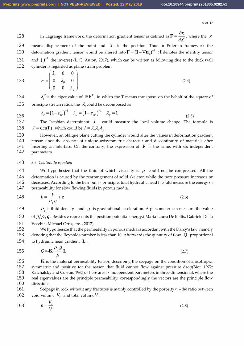
K is the material permeability tensor, describing the seepage on the condition of anisotropic,156 symmetric and positive for the reason that fluid cannot flow against pressure drop(Biot, 1972; 157 Katchalsky and Curran, 1965). There are six independent parameters in three dimensional, where the158 real eigenvalues are the principle permeability, correspondingly the vectors are the principle flow 159 directions. 160
Seepage in rock without any fractures is mainly controlled by the porosity n --the ratio between 161
void volume vV and total volumeV . 162
vVn
V= (2.8) 163
Preprints (www.preprints.org) | NOT PEER-REVIEWED | Posted: 22 May 2018 doi:10.20944/preprints201805.0282.v1
6 of 17
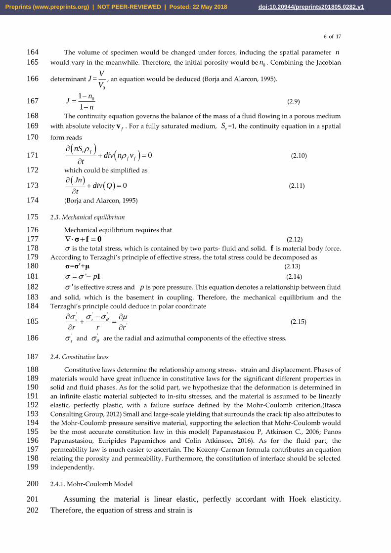
The volume of specimen would be changed under forces, inducing the spatial parameter n164
would vary in the meanwhile. Therefore, the initial porosity would be 0n . Combining the Jacobian 165
determinant
0
=V
JV
, an equation would be deduced (Borja and Alarcon, 1995). 166
01
1
nJ
n
−=
− (2.9) 167
The continuity equation governs the balance of the mass of a fluid flowing in a porous medium 168
with absolute velocityfv . For a fully saturated medium, rS =1, the continuity equation in a spatial169
form reads 170
( )( )r
0f
f f
nSdiv n v
t
+ =
(2.10) 171
which could be simplified as 172
( )( ) 0
Jndiv Q
t
+ =
(2.11) 173
(Borja and Alarcon, 1995) 174
2.3. Mechanical equilibrium 175
Mechanical equilibrium requires that 176
+ =σ f 0 (2.12) 177 is the total stress, which is contained by two parts- fluid and solid. f is material body force. 178
According to Terzaghi’s principle of effective stress, the total stress could be decomposed as 179
= +σ σ' μ (2.13) 180
' p = − I (2.14) 181
' is effective stress and p is pore pressure. This equation denotes a relationship between fluid 182
and solid, which is the basement in coupling. Therefore, the mechanical equilibrium and the183 Terzaghi’s principle could deduce in polar coordinate 184
' ''
r
'
r
r r r
− + =
(2.15) 185
'
r and '
are the radial and azimuthal components of the effective stress.186
2.4. Constitutive laws 187
Constitutive laws determine the relationship among stress,strain and displacement. Phases of 188 materials would have great influence in constitutive laws for the significant different properties in 189 solid and fluid phases. As for the solid part, we hypothesize that the deformation is determined in 190 an infinite elastic material subjected to in-situ stresses, and the material is assumed to be linearly 191 elastic, perfectly plastic, with a failure surface defined by the Mohr-Coulomb criterion.(Itasca 192 Consulting Group, 2012) Small and large-scale yielding that surrounds the crack tip also attributes to 193 the Mohr-Coulomb pressure sensitive material, supporting the selection that Mohr-Coulomb would 194 be the most accurate constitution law in this model( Papanastasiou P, Atkinson C., 2006; Panos 195 Papanastasiou, Euripides Papamichos and Colin Atkinson, 2016). As for the fluid part, the 196 permeability law is much easier to ascertain. The Kozeny-Carman formula contributes an equation 197 relating the porosity and permeability. Furthermore, the constitution of interface should be selected 198 independently. 199
2.4.1. Mohr-Coulomb Model 200
Assuming the material is linear elastic, perfectly accordant with Hoek elasticity. 201
Therefore, the equation of stress and strain is 202
Preprints (www.preprints.org) | NOT PEER-REVIEWED | Posted: 22 May 2018 doi:10.20944/preprints201805.0282.v1

7 of 17
:=σ E ε (2.16) 203 Based on the thick wall cylinder theory, the result is Lame equation 204
2 2 2 2
02 2 2 2 2 2
2 2 2 2
02 2 2 2 2 2
1 1
1 1
0
r i
i
r
a b b ap p
b a r b a r
a b b ap p
b a r b a r
= − − −
− −
= + − +
− −
=
(2.17) 205
ip is the inner pressure and 0p is the outer pressure, which is zero here. 206
However, linear elasticity is an idealized constitutive model in figuring out the infinitesimal 207 deformations when the stress applied on the cell does not reach the material’s strength 208
Furthermore, the Mohr-Coulomb yield criterion is an integral judgement describing the 209 deterioration of rock mass. The formulation is in the following. 210
+ tannc = (2.18) 211
2.4.2. Permeability 212
Water is a magical factor for its incredible effects in softening materials and particular characters 213 in uniform force. Although the hypothesis is that deformations could be induced for the elastic 214 material. This model is a hollow cylinder cut by fracture, producing an interface. The permeability 215 should be discussed as two parts: one is permeability in porous media; another is permeability in 216 single fracture. 217
As for the porous media, although displacement induced by the rearrangement of solid skeleton 218 is really small compared to elastic deformation, porosity altering is non-negligible. Based on the 219 Kozeny-Carman formula, the deformation-dependent permeability is related to the constant 220 permeability. The Kozeny-Carman formula is 221
( )
3
0 2 2k
1 s
nc
n M=
− (2.19) 222
Where k is permeability. 0c is the coefficient relating to empirical geometry. sM is specific 223
surface area. 224
At the initial state, 0n n= , ( )
3
00 0 2 2
0
k1 s
nc
n M=
− (2.20) 225
When 0t , ( )
3
0 2 2k
1 s
nc
n M=
− , (2.21) 226
k is deformation-dependent permeability. 227 Then the normalized Kozeny-Carman formula is, 228
( )
( )
2 30
0 23
0
1
1
n nk k
n n
−=
− (2.22) 229
As for the permeability in single fracture, k could be described as 2 12k d= deduced by230
Navier-Stokes equation, in which d is opening width of fracture. The interface in this model is an 231 ideal plane without width and thickness, thus d is regarded as 1 here. 232
However, anisotropic deformation is corresponding to the anisotropic permeability, which is 233 quite complicated that not only the inhomogeneous material but also the different fluid flow could 234 have different. 235
2.4.3. Interface 236
Preprints (www.preprints.org) | NOT PEER-REVIEWED | Posted: 22 May 2018 doi:10.20944/preprints201805.0282.v1

8 of 17
Joint, fault or bedding planes in geologic medium is a natural interface, as mutation of layer that 237 may control the whole deteriorate behavior of rock mass. Assuming that the broken behaviors obey 238 Coulomb Sliding, that is, the bond is either intact or broken. The key parameters of interface are 239
combined by friction, cohesion, normal stiffness nk and shear stiffness sk . If the pore pressure is 240
greater on the condition that the stress is under compressive normal force, effective tension is no 241 more exist in broken bond segment. Shear force is limited by Coulomb shear-strength criterion by the 242 relation 243
( )max tans nF cA F pA= + − (2.23) 244
c is the cohesion along the interface. is the friction angle of the interface surface. p is pore245
pressure. When shear force is more than the limitation, sliding is assumed to occur. 246 Besides, the effective normal stress on the joint might soar due to the shear displacement, 247
according to the relation 248
smax| F |: tans o
n n n
s
Fk
AK
−= + (2.24) 249
is the dilation angle of the interface surface. | F |s o is the magnitude of shear force before the 250
preceding correction is made. (Itasca Consulting Group, 2012) 251
2.5. Boundaries 252
The initial state of the specimen is that all the displacements and velocities are zero. The porosity253
0n n= , 0 0| | =0r t t = == . 254
To simulate the reservoir with high water head, we put a load on the upper plane and in the 255 hole, as an equal force as the constant water head. Besides radial direction of circumference of model 256 is confined, simulating the fracture is embedded in infinite ground. Therefore, a constant pressure is 257 applied on the upper plane while the static water pressure is also applied in the hole of cylinder. The 258 pore pressure is also ascertained when the external load is settled down. Assuming the pore pressure 259 of the upper plane is equal to the water head while the fluid will flow outward radially along the 260 radius in thick wall cylinder. However, when there is fracture with different permeability, the flow 261 path will become complicated due to the interface. The pore pressure in interface may not be 262 accordant with the pore pressure in rock specimen. 263
3. Simulation of an example264
A simulation of saturated cylinder with fractures is designed to figure out hydraulic fracturing 265 coupling with seepage field and mechanic field during the process. This discontinuity increase the 266 complexity in calculation, which applies finite difference to acquire the stress and strain distribution. 267 The research selected FLAC 3D5.01 to simulate the tests, using the Lagrangian analysis of continua 268 method to solve discontinuity problem. 269
3.1. Building a model 270
According to the Figure 1, a system of reference axes is selected, with orientation in the center of 271 the cylinder at the bottom plane. The concentric circles are located in x-z plane, of which the outward 272 radius is 50mm and the inward radius is 10mm (0.010m). Extrusion along Y axis from the x-z plane 273 is 120mm (the height of the hollow cylinder is 0.120m.). The circumference is divided into 40 equally 274 while the radius between the out circle and inner circle is divided into 10 at the ratio of 1.2. The height 275 is also divided into 20 parts equally. We select parameters of sand stone to have the simulate test. All 276 the parameters are giving in Table 1, referring to Morita (1992). 277
Table 1. Material constants used for the porous model. 278
Preprints (www.preprints.org) | NOT PEER-REVIEWED | Posted: 22 May 2018 doi:10.20944/preprints201805.0282.v1

9 of 17
Rock
mass
E(GP
a)
G(GP
a)
K(GP
a)
Cohesi
on
(MPa)
Frictio
n
(°)
n C(m/
s)
Tensio
n
(MPa)
Kn(N/
m)
Ks(N/
m)
rock 23 10 12 16 41.9 0.0
1
1.4e-
14 12 / /
interfa
ce / / / 5 15 /
1.0e-
12 / 2e8 2e8
*E: Elasticity modulus G: Shear modulus K: Bulk modulus C: Permeability coefficient. 279
The oblique plane cuts the hollow cylinder at certain angles, simulating different occurrences of 280 fractures in rock mass. We set several models with different fracture angles and water pressure to 281 mimic behaviors of varies. The angles of fractures are 0o, 15o, 30o and 45o. 282
The initial state is balanced first at the service of adding external loading. To figure out the fault 283 activation effected by the value of water head and pore pressure, normal stress is applied on the plane 284 distributed equally, regarding as water pressure. Exploration in relationship between water head and 285 the displacement is needed in this simulation, changing the water head gradually, which are 50m, 286 100m, 150m, 200m, 250m and 300m. Numerical tests had been carried out to confirm that this increase 287 of loading rate has very little influence on the material behavior of the sample. (Sousani Marina, 288 Eshiet Kenneth Imo-Imo, Ingham Derek, 2014) Therefore, the increasing rate of water pressure is not 289 set in this numerical test. 290
291
Figure 4. Contour of model with mesh and interface. 292
Since the fluid phase is existing in the saturated specimen, seepage field is a significant factor 293 that should be coupled into this simulation. Assuming the cylinder is at the bottom of a reservoir, 294 pore pressure is the same as the water pressure without considering the geotectonic stress. Besides, 295 we hypothesize that the cylinder is embed in infinite space, which means the periphery of the cylinder 296 is confined in x-z plane while the deformation of y axis is free. 297
Establish the modelSet gravity and eliminate the deformation
Add the external load equal to the
water headSet pore pressure
Coupling the fluid field and the solid
field
Compare and get the conclusion
298 Figure 5. Process of simulating hydraulic fracturing. 299
3.2. Results and discussion 300
After all the models are calculated, displacements of certain points near the interface are 301 recorded to demonstrate the deformation of holly cylinder. Furthermore, the stress and strain 302 distribution could imply the mechanism of the deterioration inside the specimen. We selected two 303 groups of points in each model. Three points are contained in each group perpendicular to the x-z 304 plane, locating in a line at the same distance. The coordinates are listed in Table 2. 305
306
Preprints (www.preprints.org) | NOT PEER-REVIEWED | Posted: 22 May 2018 doi:10.20944/preprints201805.0282.v1
10 of 17
Table 2. Coordinate of selected points. 307
Inclination 0º 15º 30º 45º
Inner circle
(0.010 0.057 0) (0.010 0.054 0) (0.010 0.051 0) (0.010 0.048 0)
(0.010 0.060 0) (0.010 0.057 0) (0.010 0.054 0) (0.010 0.051 0)
(0.010 0.063 0) (0.010 0.060 0) (0.010 0.057 0) (0.010 0.054 0)
Outer circle
(0.050 0.057 0) (0.050 0.044 0) (0.050 0.028 0) (0.050 0.007 0)
(0.050 0.060 0) (0.050 0.047 0) (0.050 0.031 0) (0.050 0.010 0)
(0.050 0.063 0) (0.050 0.050 0) (0.050 0.034 0) 013 0)
*The coordinates with underline means the point is in on the interface. Differences of displacement between308 points above or beneath the interface are recorded in mechanic field and coupling the solid phase and fluid phase. 309
Thus the difference of displacement between the two points above the interface and beneath the 310 interface would imply disturbance and discontinuity of the specimen. For the convenience of contrast 311 the displacement of point, ‘series up’ is defined as subtraction between upper grid and interface grid 312 while ‘series down’ defined as subtraction between lower grid and interface grid. Subtraction of 313 ‘series up’ and ‘series down’ could supply a relative location between hanging wall and foot wall of 314 the fault. Based on this, 8 lines are drawn in one coordinate system. 315
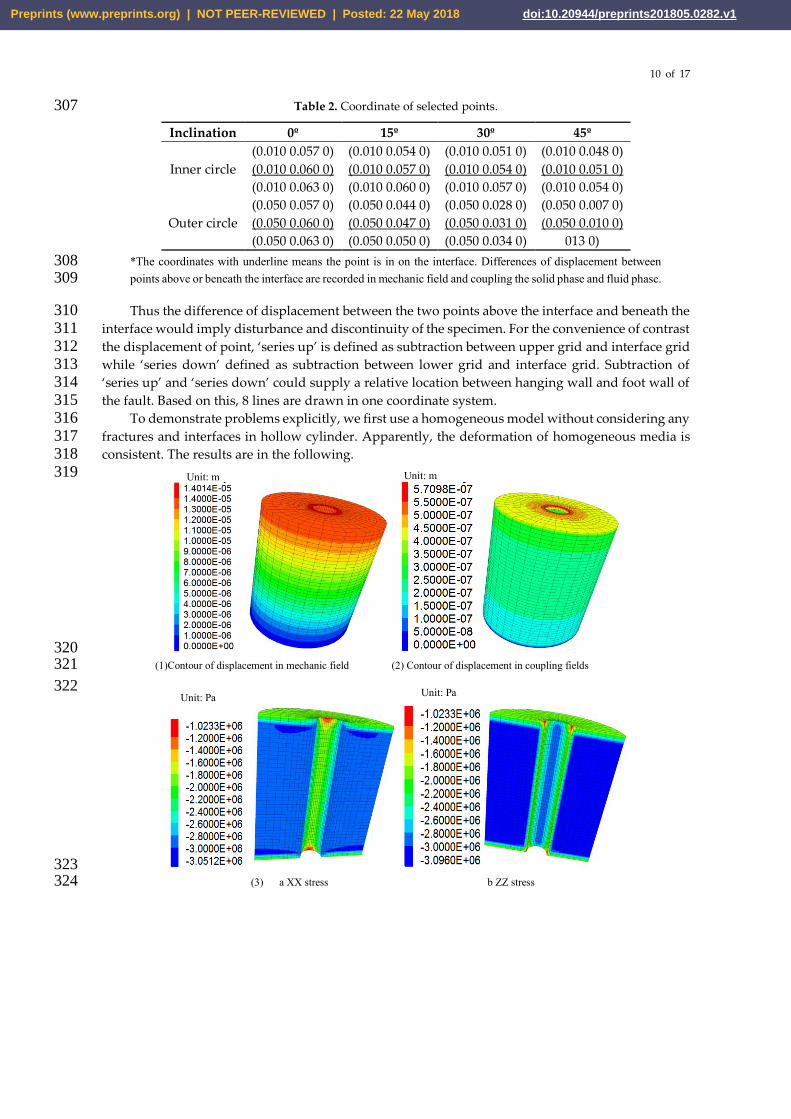
To demonstrate problems explicitly, we first use a homogeneous model without considering any 316 fractures and interfaces in hollow cylinder. Apparently, the deformation of homogeneous media is 317 consistent. The results are in the following. 318
319
320 (1)Contour of displacement in mechanic field (2) Contour of displacement in coupling fields321
322
323 (3) a XX stress b ZZ stress 324
Unit: Pa
Unit: m Unit: m
Unit: Pa
Preprints (www.preprints.org) | NOT PEER-REVIEWED | Posted: 22 May 2018 doi:10.20944/preprints201805.0282.v1
11 of 17
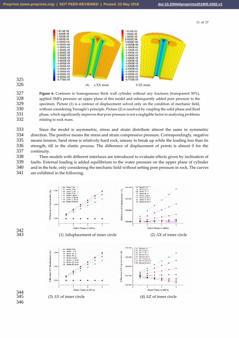
325 (4) a XX strain b ZZ strain 326
Figure 6. Contours in homogeneous thick wall cylinder without any fractures (transparent 50%), 327 applied 3MPa pressure on upper plane of this model and subsequently added pore pressure to the 328 specimen. Picture (1) is a contour of displacement solved only on the condition of mechanic field, 329 without considering Terzaghi’s principle. Picture (2) is resolved by coupling the solid phase and fluid 330 phase, which significantly improves that pore pressure is not a negligible factor in analyzing problems 331 relating to rock mass. 332
Since the model is asymmetric, stress and strain distribute almost the same in symmetric 333 direction. The positive means the stress and strain compressive pressure. Correspondingly, negative 334 means tension. Sand stone is relatively hard rock, uneasy to break up while the loading less than its 335 strength, till in the elastic process. The difference of displacement of points is almost 0 for the 336 continuity. 337
Then models with different interfaces are introduced to evaluate effects given by inclination of 338 faults. External loading is added equilibrium to the water pressure on the upper plane of cylinder 339 and in the hole, only considering the mechanic field without setting pore pressure in rock. The curves 340 are exhibited in the following. 341
342 (1) Δdisplacement of inner circle (2) ΔX of inner circle343
344 (3) ΔY of inner circle (4) ΔZ of inner circle345
346
Preprints (www.preprints.org) | NOT PEER-REVIEWED | Posted: 22 May 2018 doi:10.20944/preprints201805.0282.v1

12 of 17
347 (5) ΔDisplacement of outer circle (6) ΔY of outer circle348
Figure 7. Difference of displacements acquired by only simulating the single fracture model with 349 equilibrium water pressure, without considering the pore pressure and seepage field inside the 350 specimen. 351
These curves are quite special that difference of displacement and Y are descending while the 352 inclination of interface is increasing. Besides the slope of different models attenuates much rapidly 353 as the inclination of single fracture ascend gradually by a step of 15o On the contrary, ΔX and ΔZ are 354 rising. This phenomenon may be caused by creating micro fissures. 355
356 (1) ΔDisplacement of inner circle (2) ΔX of inner circle 357
358 (3) ΔY of inner circle (4) ΔZ of inner circle 359
360
Preprints (www.preprints.org) | NOT PEER-REVIEWED | Posted: 22 May 2018 doi:10.20944/preprints201805.0282.v1

13 of 17
(5) Δ Displacement of outer circle (6) ΔY of outer circle 361
Figure 8. Difference of displacements acquired by coupling solid phase and fluid phase. 362
According to figure 8, the differences of displacement between outer circle and inner circle imply 363 that movement of rock mass above the interface is much more than that beneath the interface. 364 Discontinuity in z direction could generate a slight fissure inside this cylinder. Besides, with the 365 increase of inclination, the difference of rock mass on the either side of the fracture also grows 366 gradually. Up planes of this fault could be activated due to the discontinuity in x axis. What’s more, 367 the cylinder with interface inclination at 0 cannot be regarded as two integral thick-wall cylinder 368 attached together because the x and z displacement of cells are supposed to be zero if the specimen 369 is homogeneous. There might be a micro fissure propagating near the interface while the water is 370 injected into the hole for the soft layer or structure plane embedded in two layers. 371
Therefore some rules could be concluded that the displacement increases linearly with the water 372 pressure and inclination of interface. The deformation of each point is mainly determined by the 373 displacement along y axis, which could be counted as millimeters in spite that the height of model is 374 120mm, although the displacement under the interface can be neglected. This data implies that the 375 deformation of this specimen is discontinues for the existence of interface, which can absorb energy 376 in the form of sliding and condensing. 377
378
379
(1)Contour of displacement in mechanic field (2) Contour of displacement in coupling fields380
381
382 (3) a XX stress b ZZ stress 383
Unit: Pa Unit: Pa
Unit: m Unit: m
Preprints (www.preprints.org) | NOT PEER-REVIEWED | Posted: 22 May 2018 doi:10.20944/preprints201805.0282.v1
14 of 17
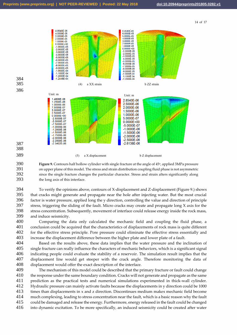
384 (4) a XX strain b ZZ strain 385
386
387 388
(5) a X displacement b Z displacement 389
Figure 9. Contours half hollow cylinder with single fracture at the angle of 45o, applied 3MPa pressure 390 on upper plane of this model. The stress and strain distribution coupling fluid phase is not asymmetric 391 since the single fracture changes the particular character. Stress and strain alters significantly along 392 the long axis of this interface. 393
To verify the opinions above, contours of X-displacement and Z-displacement (Figure 9.) shows 394 that cracks might generate and propagate near the hole after injecting water. But the most crucial 395 factor is water pressure, applied long the y direction, controlling the value and direction of principle 396 stress, triggering the sliding of the fault. Micro cracks may create and propagate long X axis for the 397 stress concentration. Subsequently, movement of interface could release energy inside the rock mass, 398 and induce seismicity. 399
Comparing the data only calculated the mechanic field and coupling the fluid phase, a 400 conclusion could be acquired that the characteristics of displacements of rock mass is quite different 401 for the effective stress principle. Pore pressure could eliminate the effective stress essentially and 402 increase the displacement difference between the higher plate and lower plate of a fault. 403
Based on the results above, these data implies that the water pressure and the inclination of 404 single fracture can really influence the characters of mechanic behaviors, which is a significant signal 405 indicating people could evaluate the stability of a reservoir. The simulation result implies that the 406 displacement line would get steeper with the crack angle. Therefore monitoring the data of 407 displacement would offer the exact description of the interface. 408
The mechanism of this model could be described that the primary fracture or fault could change 409 the response under the same boundary condition. Cracks will not generate and propagate as the same 410 prediction as the practical tests and numerical simulations experimented in thick-wall cylinder. 411 Hydraulic pressure can mainly activate faults because the displacements in y direction could be 1000 412 times than displacements in x and z direction. Discontinues medium makes mechanic field become 413 much complexing, leading to stress concentration near the fault, which is a basic reason why the fault 414 could be damaged and release the energy. Furthermore, energy released in the fault could be changed 415 into dynamic excitation. To be more specifically, an induced seismicity could be created after water 416
Unit: m Unit: m
Preprints (www.preprints.org) | NOT PEER-REVIEWED | Posted: 22 May 2018 doi:10.20944/preprints201805.0282.v1
15 of 17
injected into the model. A relation between the parameters of a dynamic excitation and the energy 417 released from the amplitude and frequency of the seismicity should be established by counting the 418 displacements and stress of every cell. 419
4. Conclusion420
Hollow cylinder cut by single fracture is discussed in this model, applied water pressure on the 421 up plane and in the hole while pore pressure is set after solving the mechanic problem, which is 422 coupling solid phase and fluid phase. According to the simulation, displacement is linearly increasing 423 with the water pressure in the same model. Differences of displacement between the high plate and 424 lower plate is decreasing when the inclination of single fracture increase under the same water 425 pressure, only considering mechanic field. On the contrary, differences of displacement will increase 426 with the inclination rise after coupling fluid phase, indicating the significant influence offered by 427 Terzaghi’s effective principle. Stress and strain distribution changes for the interface, because the 428 discontinuity alter plane strain problem into three dimensional deformation. The most particular 429 characteristic of asymmetry is totally broken up in spite that the fracture is parallel to up plane, 430 exceeding common knowledge that the mechanic behavior would be similar to homogeneous 431 cylinder. Comparing displacement in thick-wall cylinder and model with single fracture, fault could 432 be damaged compressive force offered by water pressure, thus energy could be released by 433 deformation and triggering activation of fault. These inspires people that deformation of rock mass 434 could be evaluated while impounding a reservoir for the linear rule between deformation and water 435 pressure. And hydraulic fracturing in wells utilized in exploration of shale gas should avoid fractures 436 since the ability of creating and propagating cracks would attenuate obviously based on this 437 simulation. Further study on how the seismicity effect the primary faults and creating new cracks 438 should be studied. This relation could predict other factor while monitoring some of these, deducing 439 where and how the seismicity come and act on the rock mass, deteriorating it and generating new 440 cracks. 441
Acknowledgement 442
The authors would acknowledge Dr. Guan, Dr. Du and Dr. Xu for providing good suggestions 443 in plotting figures. They gave us brilliant ideas in making the pictures looking more beautiful. 444
Funding: This work was supported by the National Natural Science Foundation-Outstanding 445 Youth Foundation (grant number 51522903), the National Natural Science Foundation of China (grant 446 numbers 41772246, U1361103, 51479094), the State Key Laboratory of Hydro-science and Engineering 447 (grant numbers 2016-KY-02, 2016-KY-04, 2016-KY-05). 448
Reference 449
[1] Ameen, M.S., 2014. Fracture and in-situ stress patterns and impact on performance in the Khuff structural450
prospects, eastern offshore Saudi Arabia. Mar. Pet.. Geol. 50, 166-184. DOI: 10.1016/j.marpetgeo.2013.10.004451
[2] Beekman, F., Badsi, M., Wees, J.D.V., 2000. Faulting, fracturing and in situ stress prediction in the Ahnet452
Basin, Algeria - a finite element approach. Tectonophysics 320, 311-329.453
[3] Biot, M. , 1972. Theory of finite deformations of pourous solids. Indiana Univ. Math. J. 21, 597–620 .454
[4] Bjerrum, L. and Andersen, K.H. 1972. In-situ Measurement of Lateral Pressures in Clay. Proc. of the 5th455
European Regional Conference on SMFE, Madrid, Spain, Vol.1,456
[5] Borja, R.I. , Alarcon, E. , 1995. A mathematical framework for finite strain elastoplastic consolidation. part457
1: balance laws, variational formulation, and linearization. Comput. Methods Appl Mech Eng 122, 145–171458
.459
[6] Brudy, M., Zoback, M.D., 1999. Drilling-induced tensile wall-fractures: implications for determination of460
in-situ stress orientation and magnitude. Int. J. Rock Mech. Min. 36, 191-215.461
[7] Charlez, P., Despax, D., 1985. The state of stress in the earth crust: its importance in petroleum engineering.462
Preprints (www.preprints.org) | NOT PEER-REVIEWED | Posted: 22 May 2018 doi:10.20944/preprints201805.0282.v1
16 of 17
14th Annual Convention Proceedings, Indonesian Petroleum Association. 2, 299-308. 463
[8] Chen, W., Ravichandran, G., 1996. An experimental technique for imposing dynamic multiaxial464
compression with mechanical confinement, Exp. Mech. 36 (2), 155–158.465
[9] Cleary, M. P., Wong, S. K., 1985, Numerical simulation of unsteady fluid flow and propagation of a circular466
hydraulic fracture. Int. J. Numer. Anal. Met. 9, 1-14467
[10] Decker, R. A. and Clemence, S. P., 1981. Laboratory Study of Hydraulic Fracturing in Clay. Proc of The 10th468
IESMFE, Stockholm, Sweden, Vol. 1, 573~575469
[11] Itasca Consulting Group, 2012. Fast Lagrangian Analysis of Continua in 3 Dimensions Manual. Theory and470
Background.471
[12] Gomberg J, Bodin P, Larson K, Dragert H, 2004. Earthquake nucleation by transient deformations caused472
by the M = 7.9 Denali, Alaska, earthquake. Nature 427:621–624473
[13] Huang Wen-xi, 1982. Some comments on research works related to rock-fill dam. Water Resources474
Hydropower Engineering, 4: 23-27.475
[14] Jaeger, J.C., Cook, N.G.W., 1979. Science Paperbacks. Fundamentals of rock mechanics, third ed., 9, pp. 251-476
252477
[15] Johnson PA, Carpenter B, Knuth M, Kaproth BM, Le Bas PY, Daub EG, Marone C, 2012. Nonlinear dynamic478
triggering of slow slip on simulated earthquake faults with implications to Earth. J Geophys Res 117, B04310479
[16] Kachanov M, Prioul R, Jocker J., 2010. Incremental linear-elastic response of rocks containing multiple480
rough fractures: similarities and differences with tractionfree cracks. Geophysics. 75(1), D1–11.481
[17] Katchalsky, A.K. , Curran, P.F. , 1965. Nonequilibrium Thermodynamics in Biophysics. Harvard University482
Press .483
[18] Kennett B., 2009.Seismic wave propagation in stratified media. Australia: National University E Press,484
Canberra; p. 288.485
[19] Kim, J., Moridis, G.J., 2015. Numerical analysis of fracture propagation during hydraulic fracturing486
operations in shale gas systems. Int. J. Rock Mech. Min. 76, 127-137.487
[20] Kranz, R.L. , 1983. Microcracks in rocks: a review. Tectonophysics 100 (1), 449–480.488
[21] L. C. Auton, C. W., 2017. MacMinn, Fron arteries to boreholes: steady-state response of a poroelastic489
cylinder to fluid injection. Proc Math Phys Eng Sci. 473, 1-19. DOI: 10.1098/rspa.2016.0753.490
[22] Li, H., Wong, L.N.Y., 2012. Influence of flaw inclination angle and loading condition on crack initiation and491
propagation. Int. J. Solids Struct. 49, 2482-2499.492
[23] Maria Laura De Bellis, Gabriele Della Vecchia, Michael Ortiz, Anna Pandolfib, 2017. A multiscale model of493
distributed fracture and permeability in solids in all-round compression. Journal of the Mechanics and494
Physics of Solids. 104, 12-31.495
[24] Moes, N., Dolbow, J., Belytschko, T., 1999. A finite element method for crack growth without remesing. Int.496
J. Numer. Meth. Eng. 46, 131-150.497
[25] Morita, N., Gray, K.E., Sroujl, F.A .A ., Jogi, P.N., 1992. Rock-property changes during reservoir compaction.498
Soc. Petrol. Eng. Formation Eval. 7 (3), 197–205. DOI: 10.2118/13099-PA .499
[26] Nagy PB, 1992. Ultrasonic classification of imperfect interfaces. J Nondestruct Eval. 11(3/4), 127–39.500
[27] Nelson, E.J., 2005. Transverse drilling-induced tensile fractures in the West Tuna area, Gippsland Basin,501
Australia: implications for the in situ stress regime. Int. J. Rock Mech. Min. Sci. 42, 361-371.502
[28] Nobari, E. S. , Lee, K. L. and Duncan, J. M., 1973. Hydraulic Fracturing in Zoned Earth and Rockfill Dams.503
Report No. TE-73-1, College of Engineering Office of Research Service, University of California, Berkley,504
California,505
Preprints (www.preprints.org) | NOT PEER-REVIEWED | Posted: 22 May 2018 doi:10.20944/preprints201805.0282.v1
17 of 17
[29] P. Grassl, C. Fahy, D. Gallipoli, S.J. Wheeler, 2015. On a 2D hydro-mechanical lattice approach for 506
modelling hydraulic fracture. Journal of the Mechanics and Physics of Solids. 75, 104-118. 507
[30] Panos Papanastasiou, Euripides Papamichos and Colin Atkinson, 2016. On the risk of hydraulic fracturing508
in CO2 geological storage. International Journal for Numerical and Analytical Methods in Geomechanics.509
40,1472-1484.510
[31] Papanastasiou P, Atkinson C., 2006. Representation of crack-tip plasticity in pressure-sensitive511
geomaterials: large scale yielding. International Journal of Fracture. 139, 137–144.512
[32] Saipeng Huang, Dameng Liu, Yanbin Yao, 2017. Natural fractures initiation and fracture type prediction513
in coal reservoir under different in-situ stresses during hydraulic fracturing. Journal of Natural Gas Science514
and Engineering. 43, 69-80.515
[33] Sousani Marina, Eshiet Kenneth Imo-Imo, Ingham Derek, 2014. Pourkashanian Mohamed, Sheng Yong,516
Modelling of hydraulic fracturing process by coupled discrete element and fluid dynamic methods.517
Environment Earth Science. 72, 3383-3399.518
[34] Spencer TW, Edwards CM, Sonnad JR, 1977. Seismic wave attenuation in nonresolvable cyclic stratification.519
Geophysics. 42(5), 939–49.520
[35] Voisin C, Campillo M, Ionescu IR, Cotton F, Scotti O, 2000. Dynamic versus static stress triggering and521
friction parameters: Interface from the November 23, 1980, Irpinia earthquake. J Geophys Res. 105, 21647–522
21659.523
[36] W. Wu, J. Zhao, 2014. A Dynamic-induced Direct-shear Model for Dynamic Triggering of Frictional Slip on524
Simulated Granular Gouges. Experimental Mechanics. 54, 605-613525
[37] Wei Wu, Haibo Li, Jian Zhao, 2015. Dynamic responses of non-welded and welded rock fractures and526
implication for P-wace attenuation in a rock mass. International Journal of Rock Mechanics & Mining527
Sciences. 77, 174-181.528
[38] Wei Wu, Zhihong Zhao, Kang Duan, 2017. Unloading-induced instability of a simulated granular fault and529
implications for excavation-induced seismicity. Tunnelling and Underground Space Technology. 63, 154-530
161.531
[39] Wong, R.H.C., Chau, K.T., Wang, P., 1996. Microcracking and grain size effect in yuen long marbles. Int. J.532
Rock Mech. Min. Sci. 33 (5), 479–485.533
[40] Xiaoxi Men, Chunan Tang, Tianhui Ma, 2014. Numerical Simulation on Influence of Rockmass Parameters534
on Fracture Propagation During Hydraulic Fracturing. Journal of Northeastern University (Natural535
Science). 34(5), 700-703.536
[41] Yao, Y., 2012. Linear elastic and cohesive fracture analysis to model hydraulic fracture in brittle and ductile537
rocks. Rock Mech. Rock Eng. 45, 375-387.538
[42] Yaping Sun, 1985. Study on Mechanism of Hydraulic Fracturing. Tsinghua university, Beijing.539
[43] Zhang Hui, 2005. Experimental Study and numerical simulation of hydraulic fracturing in core of rockfill540
dam. Hohai University, Nanjing.541
Preprints (www.preprints.org) | NOT PEER-REVIEWED | Posted: 22 May 2018 doi:10.20944/preprints201805.0282.v1
Related Documents