1 HVACR116 – Trade Skills Structural Drawings

Welcome message from author
This document is posted to help you gain knowledge. Please leave a comment to let me know what you think about it! Share it to your friends and learn new things together.
Transcript

1
HVACR116 – Trade Skills
Structural DrawingsStructural Drawings
2
Structural DrawingsStructural Drawings
3
ObjectivesObjectives
• After completing this unit, you will be able to perform the following tasks:o Describe the footings for columns and walls, including
dimensions and reinforcemento Interpret the information found on a foundation plan,
including dimensions of foundation walls, reinforcement of foundations, and the locations of the various elements

4
Objectives (cont’d.)Objectives (cont’d.)
• After completing this unit, you will be able to perform the following tasks (cont’d.):o Describe each column, beam, and lintel shown on the
structural drawingso Interpret structural details and sections
• After completing this unit, you will be able to perform the following tasks (cont’d.):o Describe each column, beam, and lintel shown on the
structural drawingso Interpret structural details and sections
5
Foundations for Commercial BuildingsFoundations for Commercial Buildings
• Foundation supports load imposed on superstructure and spreads it over a large area, so earth supports it uniformlyo Commercial construction foundation systems include
spread footings, stem walls, and padso Biggest difference is footing thickness and amount of
reinforcing steel
• Foundation supports load imposed on superstructure and spreads it over a large area, so earth supports it uniformlyo Commercial construction foundation systems include
spread footings, stem walls, and padso Biggest difference is footing thickness and amount of
reinforcing steel

6
Foundations (cont’d.)Foundations (cont’d.)
• Drawing consists of a plan showing foundation layout, major dimensions, and detail drawings o Column footing placement is indicated by referencing
structural grid coordinateso Structural grid indicates column centerline
• Drawing consists of a plan showing foundation layout, major dimensions, and detail drawings o Column footing placement is indicated by referencing
structural grid coordinateso Structural grid indicates column centerline

7
Foundations (cont’d.)Foundations (cont’d.)
Figure 39–1. The column load must be centered on the footing.
8
Structural Steel FramingStructural Steel Framing
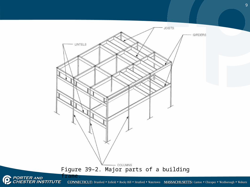
• Consists of columns (vertical) and beams (horizontal) o Girders (largest beams) attach to columnso Joists (intermediate beams) are supported at ends by
girderso Lintels are beams that support weight above an opening
• Consists of columns (vertical) and beams (horizontal) o Girders (largest beams) attach to columnso Joists (intermediate beams) are supported at ends by
girderso Lintels are beams that support weight above an opening
9
Figure 39–2. Major parts of a building frame.
10
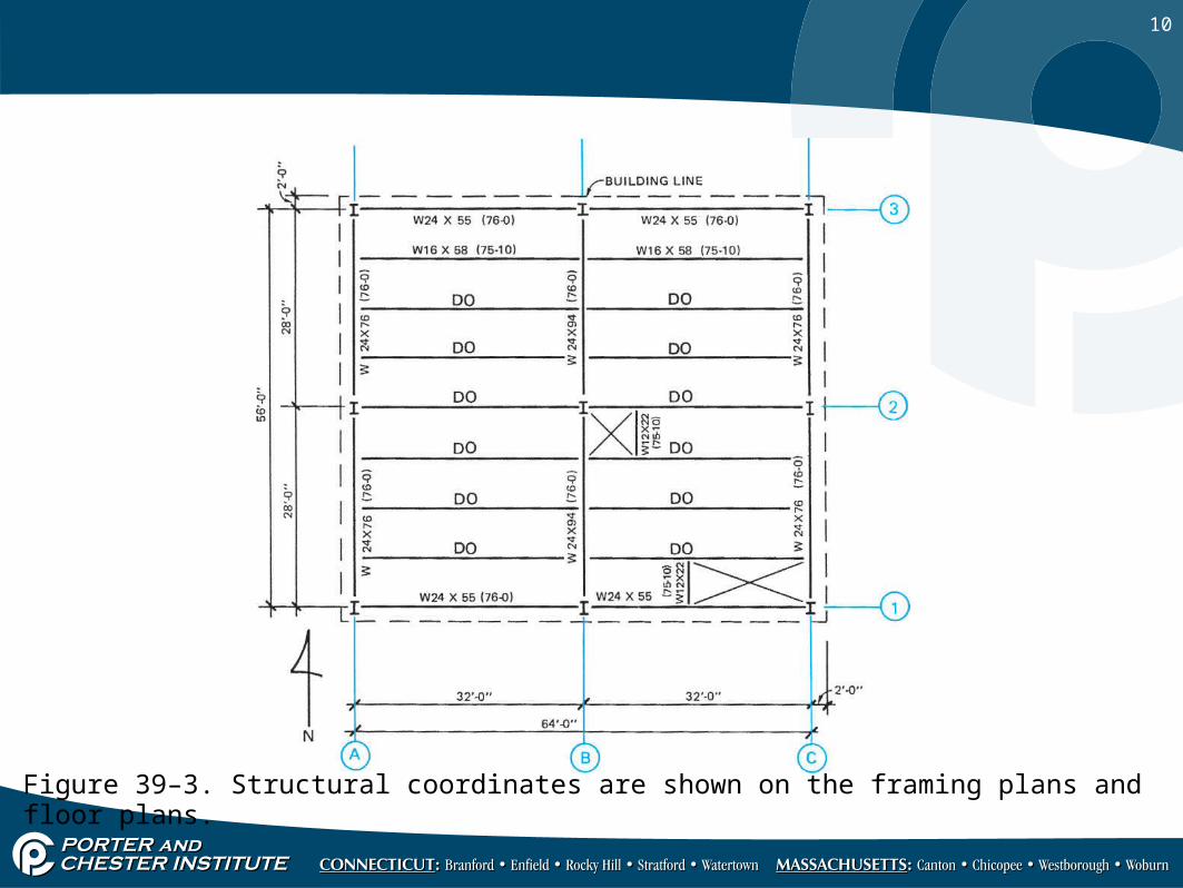
Figure 39–3. Structural coordinates are shown on the framing plans and floor plans.

11
Figure 39–4. Notations on the drawings indicate the relative elevations of beams.
Structural Steel Framing (cont’d.)Structural Steel Framing (cont’d.)
12
Structural Steel Framing (cont’d.)Structural Steel Framing (cont’d.)
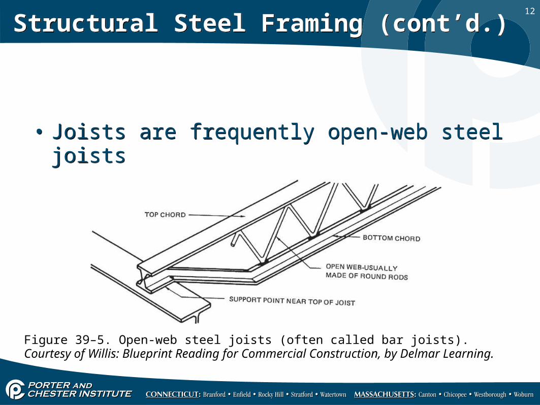
• Joists are frequently open-web steel joists• Joists are frequently open-web steel joists
Figure 39–5. Open-web steel joists (often called bar joists). Courtesy of Willis: Blueprint Reading for Commercial Construction, by Delmar Learning.
13
Structural Steel Framing (cont’d.)Structural Steel Framing (cont’d.)
• Actual lengths of members are not shown on general contract drawingso Shown on shop drawings, drawn by steel fabricator,
after construction drawings are completed
• Actual lengths of members are not shown on general contract drawingso Shown on shop drawings, drawn by steel fabricator,
after construction drawings are completed
14
Structural Steel Framing (cont’d.)Structural Steel Framing (cont’d.)
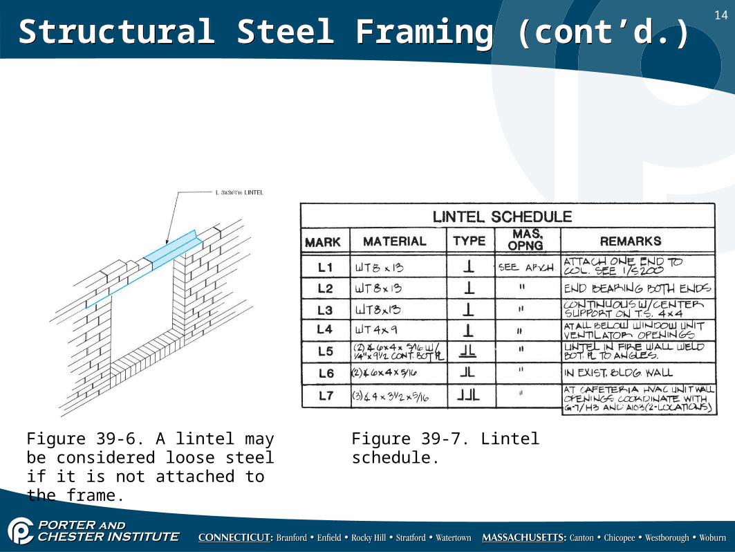
Figure 39-6. A lintel may be considered loose steel if it is not attached to the frame.
Figure 39-7. Lintel schedule.

15
Masonry ReinforcementMasonry Reinforcement
• Mortar in joints is poor at resisting forceso Reinforcement is done by embedding welded-wire
reinforcement in joints• Building walls with reinforcement bars in unit cores
and filling with concrete (grout) achieves greater strengtho Reinforcing steel ties structural elements together
• Mortar in joints is poor at resisting forceso Reinforcement is done by embedding welded-wire
reinforcement in joints• Building walls with reinforcement bars in unit cores
and filling with concrete (grout) achieves greater strengtho Reinforcing steel ties structural elements together
16
Masonry Reinforcement (cont’d.)Masonry Reinforcement (cont’d.)
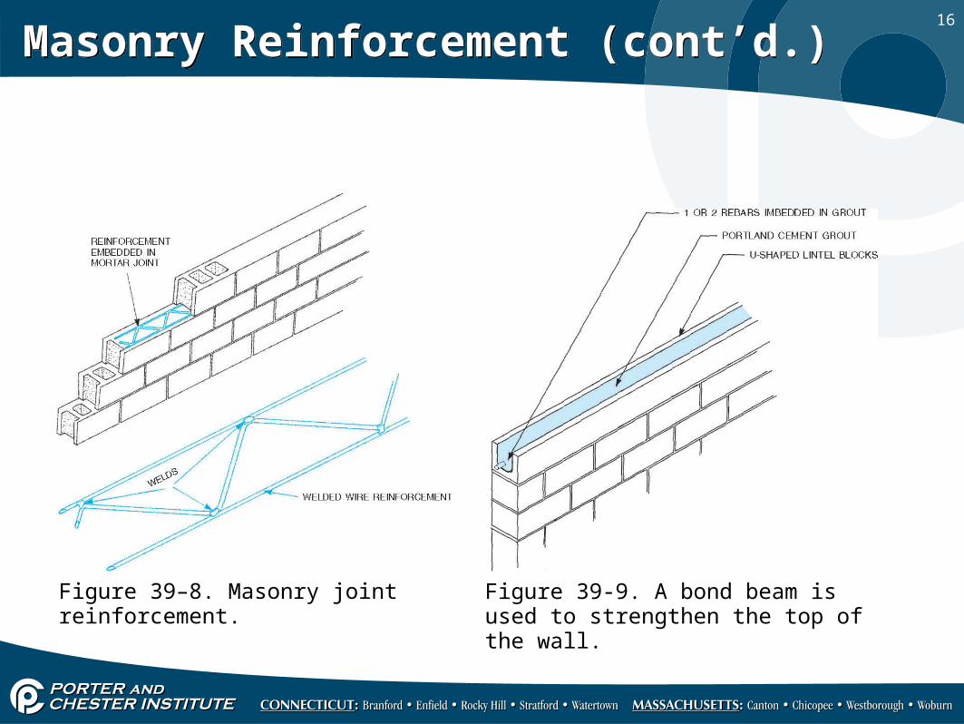
Figure 39-9. A bond beam is used to strengthen the top of the wall.
Figure 39–8. Masonry joint reinforcement.
Related Documents