Staggs and Fisher Consulting Engineers, Inc 3264 Loch Ness Drive Lexington, Kentucky 40517 Phone 859-271-3246 Fax 859-271-3246 Email [email protected] The following comments are in response to Staggs and Fisher’s review of the attached shop drawing submittal. Description of Submittal: Job Name: Job No: Date: Reviewed By: Gregory G. Carter, P.E. Daniel H. Bransom, P.E. $7DJJDUW)RVWHU3( Christopher C. Keath,P.E. John R. Mason, P.E. William P. Wilson, P.E. Greg W. Kraeszig, P.E. :D\QH$7KRPDV3( -HQQ\//HLWFK3( Member of the Consulting Engineers Council Remarks (if applicable): X REVIEWED FURNISH AS CORRECTED REJECTED REVISE AND RESUBMIT DATE: Checking is only for general conformance with the design concept of the project and general compliance with the information given in the contract documents. Any action shown is subject to the requirements of the drawings and specification. Contractor is responsible for : Quantities, dimensions which shall be confirmed and correlated at the job site, and fabrication processes and techniques of construction. BY: _______________________________________________ Gear Re-Submittal UK Chemistry Physics Building 13522 May 11, 2017 Bill Wilson May 11, 2017

Welcome message from author
This document is posted to help you gain knowledge. Please leave a comment to let me know what you think about it! Share it to your friends and learn new things together.
Transcript
Staggs and Fisher Consulting Engineers, Inc
3264 Loch Ness DriveLexington, Kentucky 40517Phone 859-271-3246Fax 859-271-3246Email [email protected]
The following comments are in response to Staggs and Fisher’s review of the attached shop drawing submittal.
Description of Submittal:
Job Name:
Job No:
Date:
Reviewed By:
Gregory G. Carter, P.E. Daniel H. Bransom, P.E.
Christopher C. Keath, P.E.John R. Mason, P.E. William P. Wilson, P.E. Greg W. Kraeszig, P.E.
Member of the Consulting Engineers Council
Remarks (if applicable):
X REVIEWED FURNISH AS CORRECTED
REJECTED REVISE AND RESUBMIT
DATE:
Checking is only for general conformance with the design concept of the project and general compliance with the information given in the contract documents. Any action shown is subject to the requirements of the drawings and specification. Contractor is responsible for : Quantities, dimensions which shall be confirmed and correlated at the job site, and fabrication processes and techniques of construction.
BY: _______________________________________________
Gear Re-Submittal
UK Chemistry Physics Building
13522
May 11, 2017
Bill Wilson
May 11, 2017
UK CHEMISTRY PHYSICS
SWITCHGEAR REPLACEMENT
CCK-2200-17
CONTRACTOR: GLENWOOD ELECTRIC INC.
GEAR RE-SUBMITTAL
DIVISION 26 ELECTRICAL SPECS
5/5/2017
bga238
Copy of review stamp template CPPD 2014.xlsx
bga238
Line
bga238
Text Box
5.11.17
bga238
Text Box
Boyd Gambrel
Eaton 9902 Windisch Rd West Chester, OH 45069 513-387-2000 - Phone 513-387-2055 - Fax
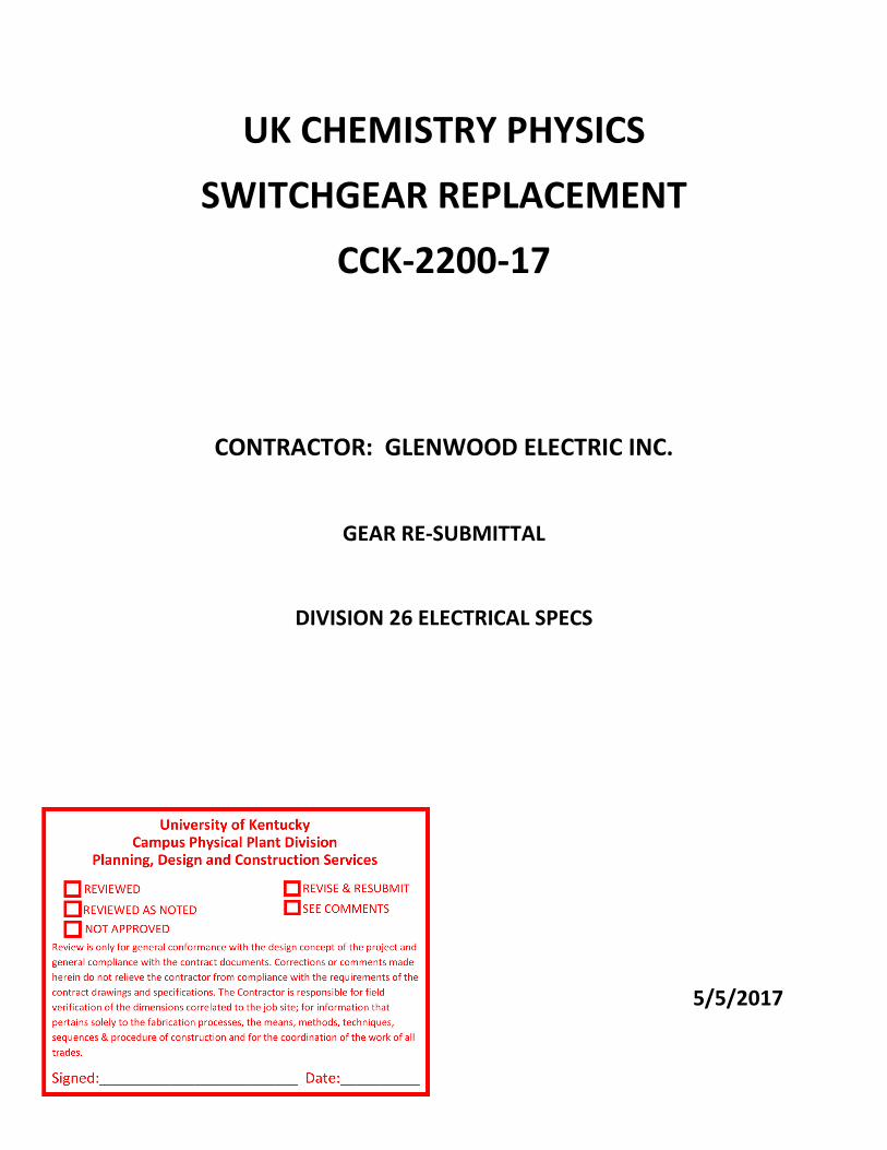
Date: May 5th, 2017 Subject: UK Chemistry Physics Gear Replacement
1. The BIL rating for the secondary side of the transformer shall be 30KV per the contract documents. • 30KV BIL will be provided
2. Provide transformer with and average winding temperature rise of 85 degrees C.
• Providing 115 deg rise per addendum 2 and conversation
3. No high winding temperature alarm is explicitly indicated. Confirm that these are being provided. • Yes this is provided, additional detail in revised submittal
4. The power to the transformer cooling system shall be internally in lieu of an external source.
• Yes, power for the transformer cooling system will be provided by switchboard secondary.
5. The bussing in the bill of material in the substation pull sections is listed as aluminum. All bussing is to be copper per the specification. Please revise.
• Eaton is providing non bussed pull structures. Any required bussing is by others.
6. Submittal indicates a PXM4000 power meter. Specifications require the meter to be a Schneider Electric PM800 series meter. Please revise. Pay special attention to the meter and CT requirements listed in the specifications.
• SQD PM800 series has been discontinued. Eaton will include SQD PM5563 meter per conversation with Bill Wilson (this meter is also referenced in spec section 262713) . CT’s are revenue grade and solid core.
7. Revise the meter location so that it is mounted no more than 5 feet above finished floor as required per the specifications.
• OK
8. The Owner has requested that the kirk key interlock system be deleted from the switchboard breaker scheme. Please omit.
• OK – Interlock scheme by others. Responsibility for safe and reliable operation by others. Thanks, Nick Quigley

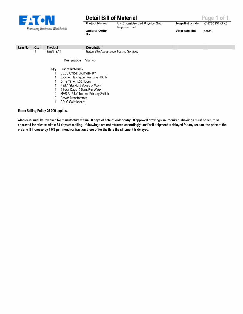
Detail Bill of Material Page 1 of 1
Project Name: UK Chemistry and Physics Gear Replacement
Negotiation No: CN750301X7K2
General Order No:
Alternate No: 0006
Item No. Qty Product Description 1 EESS SAT Eaton Site Acceptance Testing Services
Designation Start up
Qty List of Materials 1 EESS Office: Louisville, KY 1 Jobsite: , lexington, Kentucky 40517 1 Drive Time: 1.38 Hours 1 NETA Standard Scope of Work 1 8 Hour Days, 5 Days Per Week 2 MVS 5/15 kV Trnsfmr Primary Switch 2 Power Transformers 1 PRLC Switchboard
Eaton Selling Policy 25-000 applies.
All orders must be released for manufacture within 90 days of date of order entry. If approval drawings are required, drawings must be returned
approved for release within 60 days of mailing. If drawings are not returned accordingly, and/or if shipment is delayed for any reason, the price of the
order will increase by 1.0% per month or fraction there of for the time the shipment is delayed.

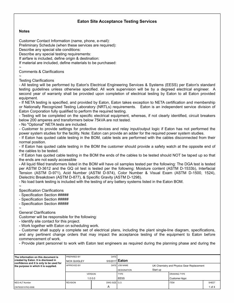
Eaton Site Acceptance Testing Services
Notes
Customer Contact Information (name, phone, e-mail):Preliminary Schedule (when these services are required):Describe any special site conditions:Describe any special testing requirements:If airfare is included, define origin & destination:If material are included, define materials to be purchased:~Comments & Clarifications~Testing Clarifications- All testing will be performed by Eaton's Electrical Engineering Services & Systems (EESS) per Eaton's standard testing guidelines unless otherwise specified. All work supervision will be by a degreed electrical engineer. A second year of warranty shall be provided upon completion of electrical testing by Eaton to all Eaton provided equipment.- If NETA testing is specified, and provided by Eaton, Eaton takes exception to NETA certification and membership or Nationally Recognized Testing Laboratory (NRTLs) requirements. Eaton is an independent service division of Eaton Corporation fully qualified to perform the required testing.- Testing will be completed on the specific electrical equipment, whereas, if not clearly identified, circuit breakers below 200 amperes and transformers below 75kVA are not tested.- No "Optional" NETA tests are included.- Customer to provide settings for protective devices and relay input/output logic if Eaton has not performed the power system studies for the facility. Note: Eaton can provide an adder for the required power system studies.- If Eaton has quoted cable testing in the BOM, cable tests are performed with the cables disconnected from their normal position.- If Eaton has quoted cable testing in the BOM the customer should provide a safety watch at the opposite end of the cables to be tested.- If Eaton has quoted cable testing in the BOM the ends of the cables to be tested should NOT be taped up so that the ends are not easily accessible- All liquid filled transformers listed in the BOM will have oil samples tested per the following: The DGA test is tested per ASTM D-3612 and the GQ oil test is tested per the following: Moisture content (ASTM D-1533b), Interfacial Tension (ASTM D-971), Acid Number (ASTM D-974), Color Number & Visual Exam (ASTM D-1500, 1524), Dielectric Breakdown (ASTM D-877), & Specific Gravity (ASTM D-1298).- No load bank testing is included with the testing of any battery systems listed in the Eaton BOM.~Specification Clarifications- Specification Section #####- Specification Section #####- Specification Section #####~General ClarificationsCustomer will be responsible for the following:- Identify site contact for this project.- Work together with Eaton on scheduling work.- Customer shall supply a complete set of electrical plans, including the plant single-line diagram, specifications, and any pertinent change orders that may impact the acceptance testing of the equipment to Eaton before commencement of work.- Provide plant personnel to work with Eaton test engineers as required during the planning phase and during the
NEG-ALT Number
PREPARED BY DATE
APPROVED BY DATE
VERSION
REVISION DWG SIZE
JOB NAME
DESIGNATION
TYPE
G.O.
DRAWING TYPE
ITEM SHEET
The information on this document is created by Eaton. It is disclosed in confidence and it is only to be used for the purpose in which it is supplied.
CN750301X7K2-0006
NICK QUIGLEY 5/5/2017
1.0.0.0
A
EatonUK Chemistry and Physics Gear ReplacementStart up
EESS Customer Appr.
1 of 4
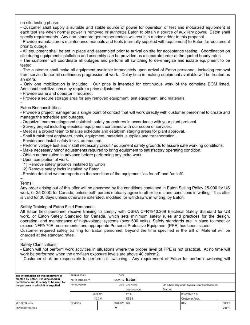
on-site testing phase.- Customer shall supply a suitable and stable source of power for operation of test and motorized equipment at each test site when normal power is removed or authorize Eaton to obtain a source of auxiliary power. Eaton shall specify requirements. Any non-standard generators rentals will result in a price adder to this proposal.- Provide manufacturers maintenance manuals and tools (normally supplied with equipment) to Eaton for equipment prior to outage.- All equipment shall be set in place and assembled prior to arrival on site for acceptance testing. Coordination on site during equipment installation and assembly can be provided as a separate order at the quoted hourly rates.- The customer will coordinate all outages and perform all switching to de-energize and isolate equipment to be tested.- The customer shall make all equipment available immediately upon arrival of Eaton personnel, including removal from service to permit continuous progression of work. Delay time in making equipment available will be treated as an extra.- Only one mobilization is included. Our price is intended for continuous work of the complete BOM listed. Additional mobilizations may require a price adjustment.- Provide crane and operator if required.- Provide a secure storage area for any removed equipment, test equipment, and materials.~Eaton Responsibilities:- Provide a project manager as a single point of contact that will work directly with customer perso nnel to create and manage the schedule and outages.- Organize team meetings and establish safety procedures in accordance with your plant protocol.- Survey project including electrical equipment contained with our scope of services.- Meet as a project team to finalize schedule and establish staging areas for plant approval.- Shall furnish test engineers, tools, equipment, materials, supplies and transportation.- Provide and install safety locks, as required.- Perform voltage test and install necessary circuit / equipment safety grounds to assure safe working conditions.- Make necessary minor adjustments required to bring equipment to satisfactory operating condition.- Obtain authorization in advance before performing any extra work.- Upon completion of work:
1) Remove safety grounds installed by Eaton2) Remove safety locks installed by Eaton.
- Provide detailed written reports on the condition of the equipment "as found" and "as left".~Terms:Any order arising out of this offer will be governed by the conditions contained in Eaton Selling Policy 25-000 for US work, or 25-000C for Canada, unless both parties mutually agree to other terms and conditions in writing. This offer is valid for 30 days unless otherwise extended, modified, or withdrawn, in writing, by Eaton.~Safety Training of Eaton Field Personnel:All Eaton field personnel receive training to comply with OSHA CFR1910.269 Electrical Safety Standard for US work, or Eaton Safety Standard for Canada, which sets minimum safety rules and practices for the design, operation, and maintenance of high-voltage systems (over 600 volts). Safety standards are in place to meet or exceed NFPA 70E requirements, and appropriate Personal Protective Equipment (PPE) has been issued.Customer required safety training for Eaton personnel, beyond the time specified in the Bill of Material will be charged at the standard rates.~Safety Clarifications:- Eaton will not perform work activities in situations where the proper level of PPE is not practical. At no time will work be performed when the arc-flash exposure levels are above 40 cal/cm2.- Customer shall be responsible to perform all switching. Any requirement of Eaton for perform switching will
NEG-ALT Number
PREPARED BY DATE
APPROVED BY DATE
VERSION
REVISION DWG SIZE
JOB NAME
DESIGNATION
TYPE
G.O.
DRAWING TYPE
ITEM SHEET
The information on this document is created by Eaton. It is disclosed in confidence and it is only to be used for the purpose in which it is supplied.
CN750301X7K2-0006
NICK QUIGLEY 5/5/2017
1.0.0.0
A
EatonUK Chemistry and Physics Gear ReplacementStart up
EESS Customer Appr.
2 of 4
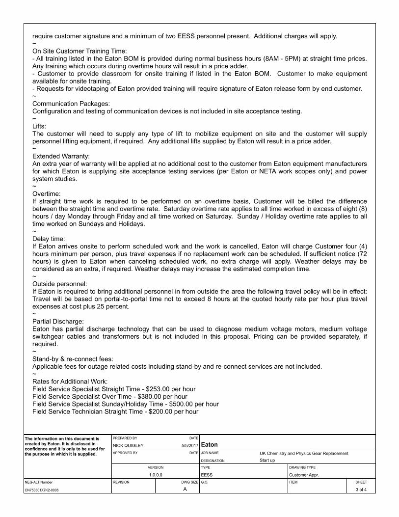
require customer signature and a minimum of two EESS personnel present. Additional charges will apply.~On Site Customer Training Time:- All training listed in the Eaton BOM is provided during normal business hours (8AM - 5PM) at straight time prices. Any training which occurs during overtime hours will result in a price adder.- Customer to provide classroom for onsite training if listed in the Eaton BOM. Customer to make equipment available for onsite training.- Requests for videotaping of Eaton provided training will require signature of Eaton release form by end customer.~Communication Packages:Configuration and testing of communication devices is not included in site acceptance testing.~Lifts:The customer will need to supply any type of lift to mobilize equipment on site and the customer will supply personnel lifting equipment, if required. Any additional lifts supplied by Eaton will result in a price adder.~Extended Warranty:An extra year of warranty will be applied at no additional cost to the customer from Eaton equipment manufacturers for which Eaton is supplying site acceptance testing services (per Eaton or NETA work scopes only) and power system studies.~Overtime:If straight time work is required to be performed on an overtime basis, Customer will be billed the difference between the straight time and overtime rate. Saturday overtime rate applies to all time worked in excess of eight (8) hours / day Monday through Friday and all time worked on Saturday. Sunday / Holiday overtime rate applies to all time worked on Sundays and Holidays.~Delay time:If Eaton arrives onsite to perform scheduled work and the work is cancelled, Eaton will charge Customer four (4) hours minimum per person, plus travel expenses if no replacement work can be scheduled. If sufficient notice (72 hours) is given to Eaton when canceling scheduled work, no extra charge will apply. Weather delays may be considered as an extra, if required. Weather delays may increase the estimated completion time.~Outside personnel:If Eaton is required to bring additional personnel in from outside the area the following travel policy will be in effect: Travel will be based on portal-to-portal time not to exceed 8 hours at the quoted hourly rate per hour plus travel expenses at cost plus 25 percent.~Partial Discharge:Eaton has partial discharge technology that can be used to diagnose medium voltage motors, medium voltage switchgear cables and transformers but is not included in this proposal. Pricing can be provided separately, if required.~Stand-by & re-connect fees:Applicable fees for outage related costs including stand-by and re-connect services are not included.~Rates for Additional Work:Field Service Specialist Straight Time - $253.00 per hourField Service Specialist Over Time - $380.00 per hourField Service Specialist Sunday/Holiday Time - $500.00 per hourField Service Technician Straight Time - $200.00 per hour
NEG-ALT Number
PREPARED BY DATE
APPROVED BY DATE
VERSION
REVISION DWG SIZE
JOB NAME
DESIGNATION
TYPE
G.O.
DRAWING TYPE
ITEM SHEET
The information on this document is created by Eaton. It is disclosed in confidence and it is only to be used for the purpose in which it is supplied.
CN750301X7K2-0006
NICK QUIGLEY 5/5/2017
1.0.0.0
A
EatonUK Chemistry and Physics Gear ReplacementStart up
EESS Customer Appr.
3 of 4
Field Service Technician Over Time - $300.00 per hourField Service Technician Sunday/Holiday Time - $400.00 per hourOther Labor Classifications will be billed per the current Engineering Services Rate Schedule (Ref: PL02700001E)
Comments and Clarifications
See above.
NEG-ALT Number
PREPARED BY DATE
APPROVED BY DATE
VERSION
REVISION DWG SIZE
JOB NAME
DESIGNATION
TYPE
G.O.
DRAWING TYPE
ITEM SHEET
The information on this document is created by Eaton. It is disclosed in confidence and it is only to be used for the purpose in which it is supplied.
CN750301X7K2-0006
NICK QUIGLEY 5/5/2017
1.0.0.0
A
EatonUK Chemistry and Physics Gear ReplacementStart up
EESS Customer Appr.
4 of 4


Detail Bill of Material Page 1 of 1
Project Name: UK Chemistry and Physics Gear Replacement
Negotiation No: CN750301X7K2
General Order No:
Alternate No: 0006
Item No. Qty Product Description 1 Medium Voltage
Assemblies MVS NEW 15KV 50A Fuses and Lighting Arrestors. WESTINGHOUSE GO# CN21734 item 1.
Designation MVS FUSES
Eaton Selling Policy 25-000 applies.
All orders must be released for manufacture within 90 days of date of order entry. If approval drawings are required, drawings must be returned
approved for release within 60 days of mailing. If drawings are not returned accordingly, and/or if shipment is delayed for any reason, the price of the
order will increase by 1.0% per month or fraction there of for the time the shipment is delayed.


Comments & Clarifications
NEW 15KV 50A Fuses and Lighting Arrestors. WESTINGHOUSE GO# CN21734 item 1.


Detail Bill of Material Page 1 of 1
Project Name: UK Chemistry and Physics Gear Replacement
Negotiation No: CN750301X7K2
General Order No:
Alternate No: 0006
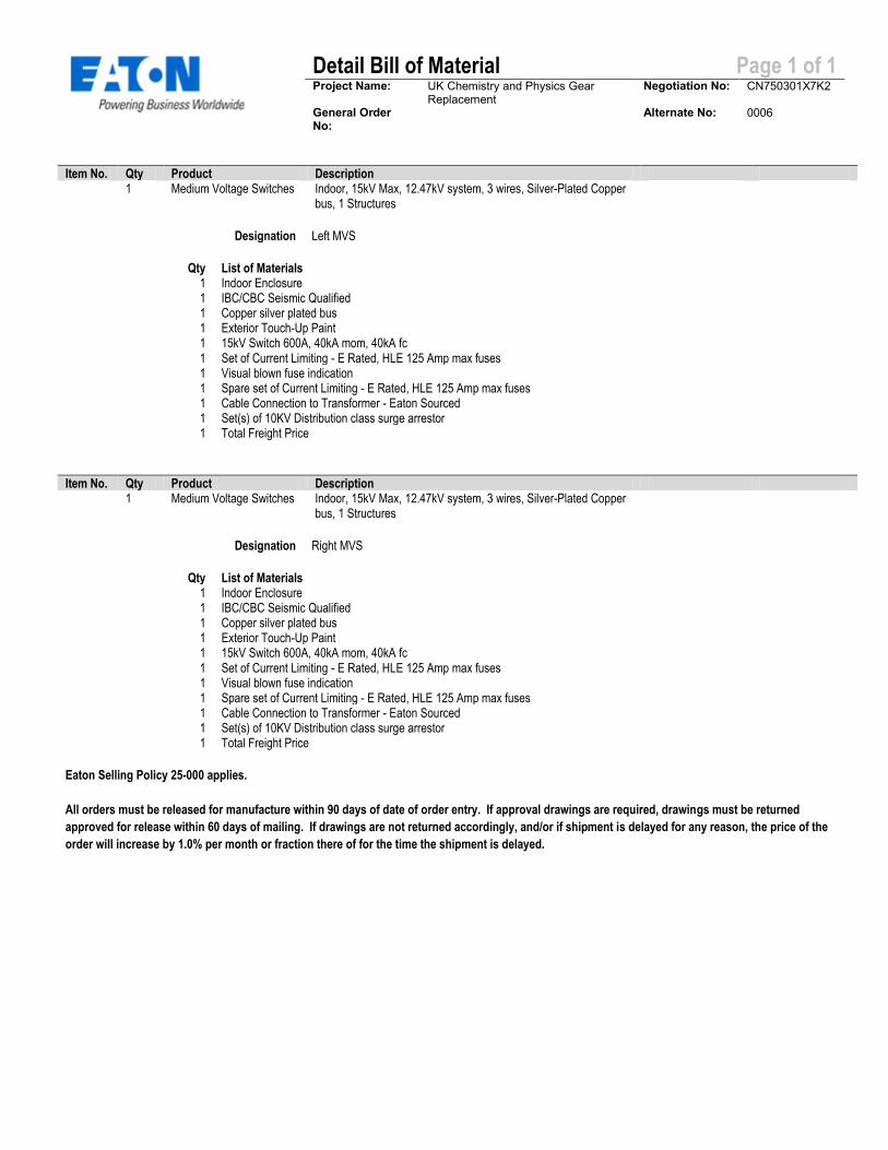
Item No. Qty Product Description 1 Medium Voltage Switches Indoor, 15kV Max, 12.47kV system, 3 wires, Silver-Plated Copper
bus, 1 Structures
Designation Left MVS
Qty List of Materials 1 Indoor Enclosure 1 IBC/CBC Seismic Qualified 1 Copper silver plated bus 1 Exterior Touch-Up Paint 1 15kV Switch 600A, 40kA mom, 40kA fc 1 Set of Current Limiting - E Rated, HLE 125 Amp max fuses 1 Visual blown fuse indication 1 Spare set of Current Limiting - E Rated, HLE 125 Amp max fuses 1 Cable Connection to Transformer - Eaton Sourced 1 Set(s) of 10KV Distribution class surge arrestor 1 Total Freight Price
Item No. Qty Product Description 1 Medium Voltage Switches Indoor, 15kV Max, 12.47kV system, 3 wires, Silver-Plated Copper
bus, 1 Structures
Designation Right MVS
Qty List of Materials 1 Indoor Enclosure 1 IBC/CBC Seismic Qualified 1 Copper silver plated bus 1 Exterior Touch-Up Paint 1 15kV Switch 600A, 40kA mom, 40kA fc 1 Set of Current Limiting - E Rated, HLE 125 Amp max fuses 1 Visual blown fuse indication 1 Spare set of Current Limiting - E Rated, HLE 125 Amp max fuses 1 Cable Connection to Transformer - Eaton Sourced 1 Set(s) of 10KV Distribution class surge arrestor 1 Total Freight Price
Eaton Selling Policy 25-000 applies.
All orders must be released for manufacture within 90 days of date of order entry. If approval drawings are required, drawings must be returned
approved for release within 60 days of mailing. If drawings are not returned accordingly, and/or if shipment is delayed for any reason, the price of the
order will increase by 1.0% per month or fraction there of for the time the shipment is delayed.

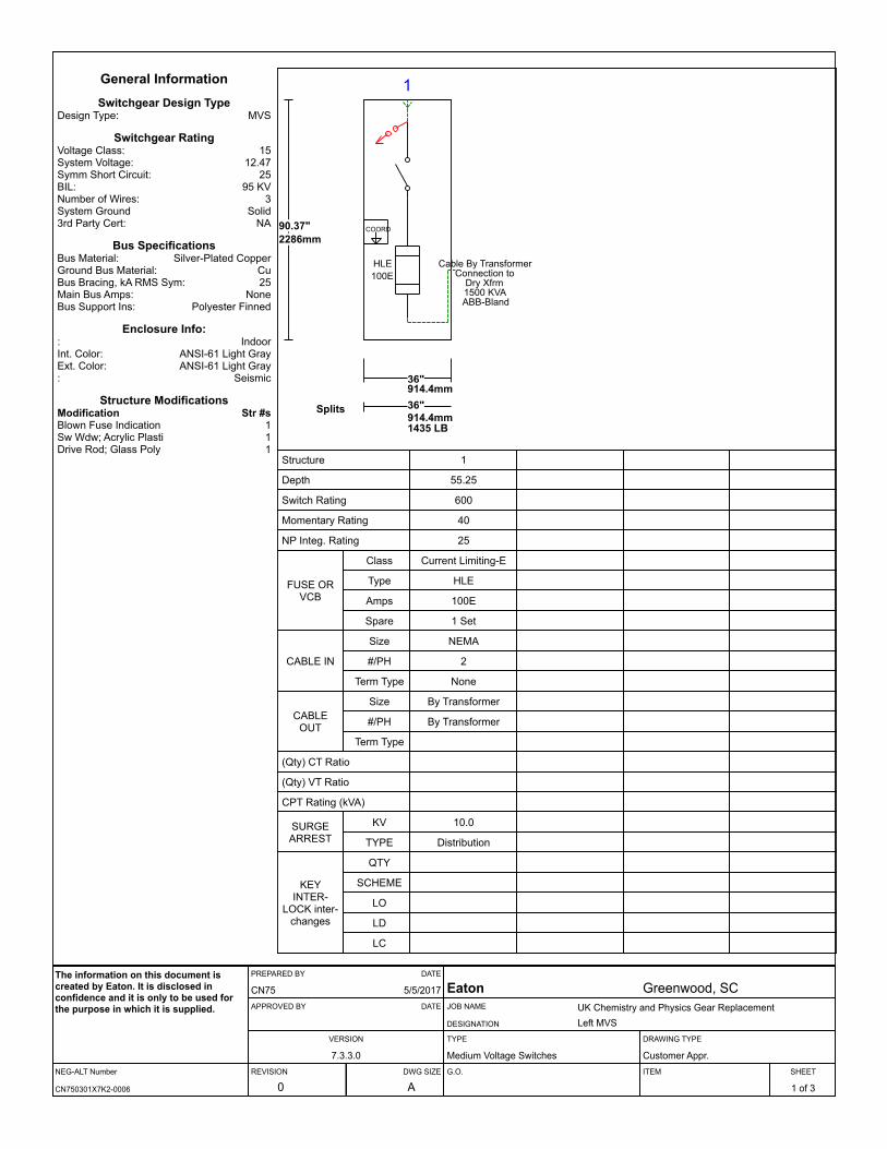
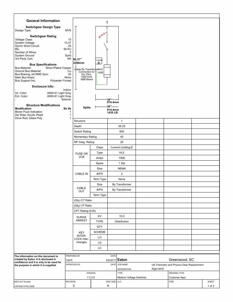
1
HLE100E
Cable By TransformerConnection to
Dry Xfrm1500 KVAABB-Bland
COORD90.37"2286mm
36"914.4mm
Splits 36"914.4mm1435 LB
General InformationSwitchgear Design Type
Design Type: MVS
Switchgear RatingVoltage Class: 15System Voltage: 12.47Symm Short Circuit: 25BIL: 95 KVNumber of Wires: 3System Ground Solid3rd Party Cert: NA
Bus SpecificationsBus Material: Silver-Plated CopperGround Bus Material: CuBus Bracing, kA RMS Sym: 25Main Bus Amps: NoneBus Support Ins: Polyester Finned
Enclosure Info:: IndoorInt. Color: ANSI-61 Light GrayExt. Color: ANSI-61 Light Gray: Seismic
Structure ModificationsModification Str #sBlown Fuse Indication 1Sw Wdw; Acrylic Plastic (Std) 1Drive Rod; Glass Poly 1
Structure 1
Depth 55.25
Switch Rating 600
Momentary Rating 40
NP Integ. Rating 25
FUSE OR VCB
Class Current Limiting-E
Type HLE
Amps 100E
Spare 1 Set
CABLE IN
Size NEMA
#/PH 2
Term Type None
CABLE OUT
Size By Transformer
#/PH By Transformer
Term Type
(Qty) CT Ratio
(Qty) VT Ratio
CPT Rating (kVA)
SURGE ARREST
KV 10.0
TYPE Distribution
KEY INTER-
LOCK inter-changes
QTY
SCHEME
LO
LD
LC
NEG-ALT Number
PREPARED BY DATE
APPROVED BY DATE
VERSION
REVISION DWG SIZE
JOB NAME
DESIGNATION
TYPE
G.O.
DRAWING TYPE
ITEM SHEET
The information on this document is created by Eaton. It is disclosed in confidence and it is only to be used for the purpose in which it is supplied.
CN750301X7K2-0006
CN75 5/5/2017
7.3.3.0
0 A
Eaton Greenwood, SCUK Chemistry and Physics Gear ReplacementLeft MVS
Medium Voltage Switches Customer Appr.
1 of 3
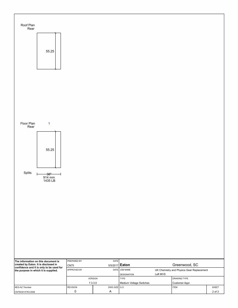
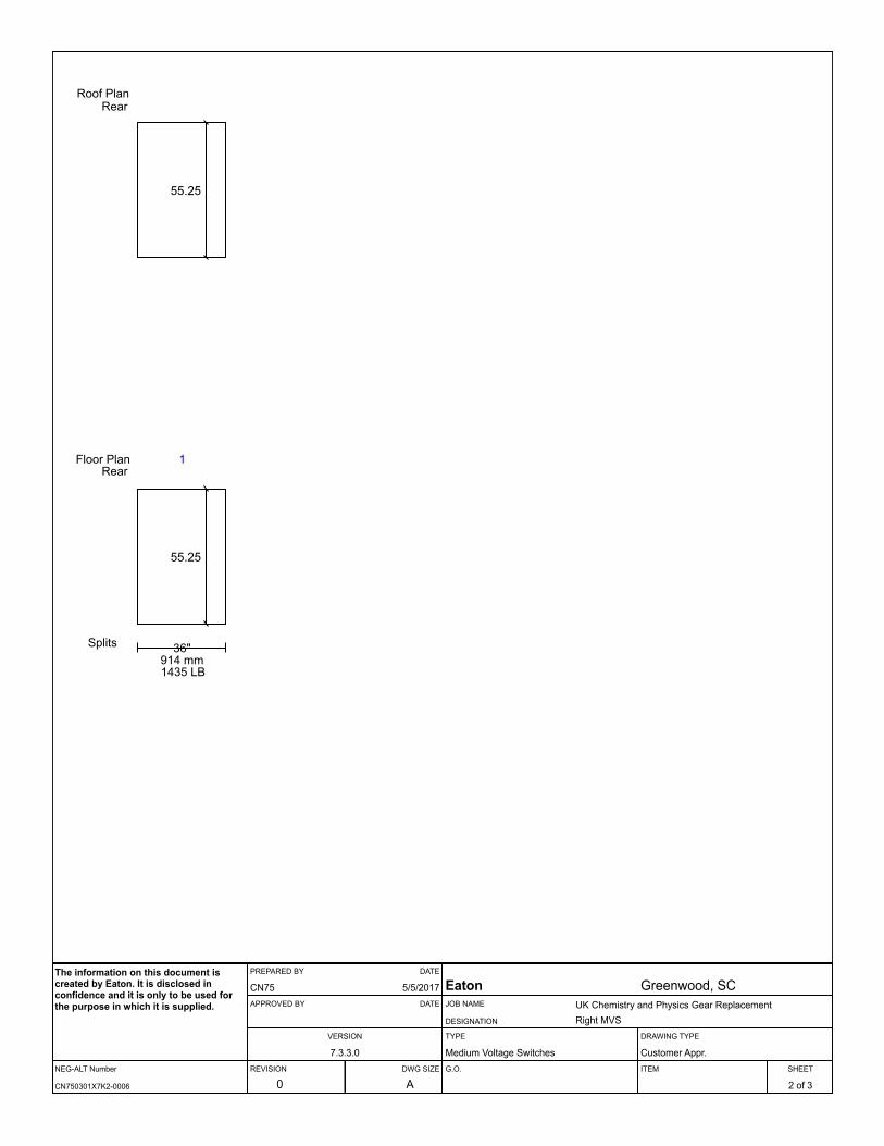
55.25
1
Splits 36"914 mm1435 LB
Floor PlanRear
55.25
Roof PlanRear
NEG-ALT Number
PREPARED BY DATE
APPROVED BY DATE
VERSION
REVISION DWG SIZE
JOB NAME
DESIGNATION
TYPE
G.O.
DRAWING TYPE
ITEM SHEET
The information on this document is created by Eaton. It is disclosed in confidence and it is only to be used for the purpose in which it is supplied.
CN750301X7K2-0006
CN75 5/5/2017
7.3.3.0
0 A
Eaton Greenwood, SCUK Chemistry and Physics Gear ReplacementLeft MVS
Medium Voltage Switches Customer Appr.
2 of 3

Comments & Clarifications
It is the purchaser's responsibility to assure the fuses offered will coordinatewith other protective devices and provide the desired system and deviceprotection.
NEG-ALT Number
PREPARED BY DATE
APPROVED BY DATE
VERSION
REVISION DWG SIZE
JOB NAME
DESIGNATION
TYPE
G.O.
DRAWING TYPE
ITEM SHEET
The information on this document is created by Eaton. It is disclosed in confidence and it is only to be used for the purpose in which it is supplied.
CN750301X7K2-0006
CN75 5/5/2017
7.3.3.0
0 A
Eaton Greenwood, SCUK Chemistry and Physics Gear ReplacementLeft MVS
Medium Voltage Switches Customer Appr.
3 of 3
1
HLE100E
Cable By TransformerConnection to
Dry Xfrm1500 KVAABB-Bland
COORD90.37"2286mm
36"914.4mm
Splits 36"914.4mm1435 LB
General InformationSwitchgear Design Type
Design Type: MVS
Switchgear RatingVoltage Class: 15System Voltage: 12.47Symm Short Circuit: 25BIL: 95 KVNumber of Wires: 3System Ground Solid3rd Party Cert: NA
Bus SpecificationsBus Material: Silver-Plated CopperGround Bus Material: CuBus Bracing, kA RMS Sym: 25Main Bus Amps: NoneBus Support Ins: Polyester Finned
Enclosure Info:: IndoorInt. Color: ANSI-61 Light GrayExt. Color: ANSI-61 Light Gray: Seismic
Structure ModificationsModification Str #sBlown Fuse Indication 1Sw Wdw; Acrylic Plastic (Std) 1Drive Rod; Glass Poly 1
Structure 1
Depth 55.25
Switch Rating 600
Momentary Rating 40
NP Integ. Rating 25
FUSE OR VCB
Class Current Limiting-E
Type HLE
Amps 100E
Spare 1 Set
CABLE IN
Size NEMA
#/PH 2
Term Type None
CABLE OUT
Size By Transformer
#/PH By Transformer
Term Type
(Qty) CT Ratio
(Qty) VT Ratio
CPT Rating (kVA)
SURGE ARREST
KV 10.0
TYPE Distribution
KEY INTER-
LOCK inter-changes
QTY
SCHEME
LO
LD
LC
NEG-ALT Number
PREPARED BY DATE
APPROVED BY DATE
VERSION
REVISION DWG SIZE
JOB NAME
DESIGNATION
TYPE
G.O.
DRAWING TYPE
ITEM SHEET
The information on this document is created by Eaton. It is disclosed in confidence and it is only to be used for the purpose in which it is supplied.
CN750301X7K2-0006
CN75 5/5/2017
7.3.3.0
0 A
Eaton Greenwood, SCUK Chemistry and Physics Gear ReplacementRight MVS
Medium Voltage Switches Customer Appr.
1 of 3
55.25
1
Splits 36"914 mm1435 LB
Floor PlanRear
55.25
Roof PlanRear
NEG-ALT Number
PREPARED BY DATE
APPROVED BY DATE
VERSION
REVISION DWG SIZE
JOB NAME
DESIGNATION
TYPE
G.O.
DRAWING TYPE
ITEM SHEET
The information on this document is created by Eaton. It is disclosed in confidence and it is only to be used for the purpose in which it is supplied.
CN750301X7K2-0006
CN75 5/5/2017
7.3.3.0
0 A
Eaton Greenwood, SCUK Chemistry and Physics Gear ReplacementRight MVS
Medium Voltage Switches Customer Appr.
2 of 3
Comments & Clarifications
It is the purchaser's responsibility to assure the fuses offered will coordinatewith other protective devices and provide the desired system and deviceprotection.
NEG-ALT Number
PREPARED BY DATE
APPROVED BY DATE
VERSION
REVISION DWG SIZE
JOB NAME
DESIGNATION
TYPE
G.O.
DRAWING TYPE
ITEM SHEET
The information on this document is created by Eaton. It is disclosed in confidence and it is only to be used for the purpose in which it is supplied.
CN750301X7K2-0006
CN75 5/5/2017
7.3.3.0
0 A
Eaton Greenwood, SCUK Chemistry and Physics Gear ReplacementRight MVS
Medium Voltage Switches Customer Appr.
3 of 3

8.0-2
For more information, visit:
www.eaton.com/consultants
CA08104001E
September 2011
Metal-Enclosed Switchgear—MVS Medium Voltage
i
ii
1
2
3
4
5
6
7
8
9
10
11
12
13
14
15
16
17
18
19
20
21
Sheet
08
Load Interrupter Fusible Switch
General Description
002
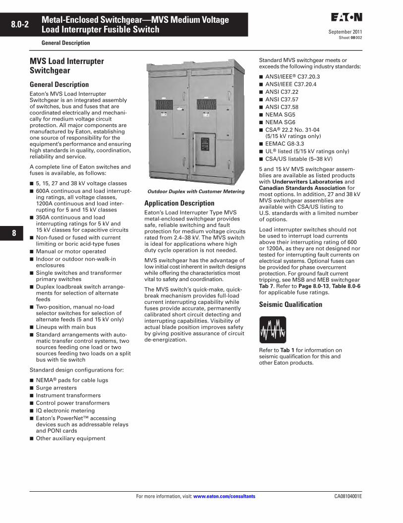
MVS Load Interrupter Switchgear
General Description
Eaton’s MVS Load Interrupter Switchgear is an integrated assembly of switches, bus and fuses that are coordinated electrically and mechani-cally for medium voltage circuit protection. All major components are manufactured by Eaton, establishing one source of responsibility for the equipment’s performance and ensuring high standards in quality, coordination, reliability and service.
A complete line of Eaton switches and fuses is available, as follows:
■
5, 15, 27 and 38 kV voltage classes
■
600A continuous and load interrupt-ing ratings, all voltage classes, 1200A continuous and load inter-rupting for 5 and 15 kV classes
■
350A continuous and load interrupting ratings for 5 kV and 15 kV classes for capacitive circuits
■
Non-fused or fused with current limiting or boric acid-type fuses
■
Manual or motor operated
■
Indoor or outdoor non-walk-in enclosures
■
Single switches and transformer primary switches
■
Duplex loadbreak switch arrange-ments for selection of alternate feeds
■
Two-position, manual no-load selector switches for selection of alternate feeds (5 and 15 kV only)
■
Lineups with main bus
■
Standard arrangements with auto-matic transfer control systems, two sources feeding one load or two sources feeding two loads on a split bus with tie switch
Standard design configurations for:
■
NEMA
®
pads for cable lugs
■
Surge arresters
■
Instrument transformers
■
Control power transformers
■
IQ electronic metering
■
Eaton’s PowerNet™
accessing devices such as addressable relays and PONI cards
■
Other auxiliary equipment
Outdoor Duplex with Customer Metering
Application Description
Eaton’s Load Interrupter Type MVS metal-enclosed switchgear provides safe, reliable switching and fault protection for medium voltage circuits rated from 2.4–38 kV. The MVS switch is ideal for applications where high duty cycle operation is not needed.
MVS switchgear has the advantage of low initial cost inherent in switch designs while offering the characteristics most vital to safety and coordination.
The MVS switch’s quick-make, quick-break mechanism provides full-load current interrupting capability while fuses provide accurate, permanently calibrated short circuit detecting and interrupting capabilities. Visibility of actual blade position improves safety by giving positive assurance of circuit de-energization.
Standard MVS switchgear meets or exceeds the following industry standards:
■
ANSI/IEEE
®
C37.20.3
■
ANSI/IEEE C37.20.4
■
ANSI C37.22
■
ANSI C37.57
■
ANSI C37.58
■
NEMA SG5
■
NEMA SG6
■
CSA
®
22.2 No. 31-04 (5/15 kV ratings only)
■
EEMAC G8-3.3
■
UL
®
listed (5/15 kV ratings only)
■
CSA/US listable (5–38 kV)
5 and 15 kV MVS switchgear assem-blies are available as listed products with
Underwriters Laboratories
and
Canadian Standards Association
for most options. In addition, 27 and 38 kV MVS switchgear assemblies are available with CSA/US listing to U.S. standards with a limited number of options.
Load interrupter switches should not be used to interrupt load currents above their interrupting rating of 600 or 1200A, as they are not designed nor tested for interrupting fault currents on electrical systems. Optional fuses can be provided for phase overcurrent protection
. For ground
fault current tripping, see MSB and MEB switchgear
Tab 7
. Refer to
Page 8.0-13
,
Table 8.0-6
for applicable fuse ratings.
Seismic Qualification
Refer to
Tab 1
for information on seismic qualification for this and other Eaton products.
CA08104001E For more information, visit:
www.eaton.com/consultants
8.0-3
September 2011
Metal-Enclosed Switchgear—MVS Medium Voltage
i
ii
1
2
3
4
5
6
7
8
9
10
11
12
13
14
15
16
17
18
19
20
21
Sheet
08
Load Interrupter Fusible Switch
General Description
003
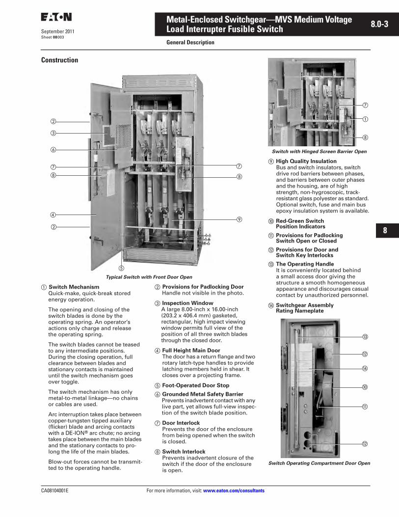
Construction
Typical Switch with Front Door Open
�
Switch Mechanism
Quick-make, quick-break stored energy operation.
The opening and closing of the switch blades is done by the operating spring. An operator’s actions only charge and release the operating spring.
The switch blades cannot be teased to any intermediate positions. During the closing operation, full clearance between blades and stationary contacts is maintained until the switch mechanism goes over toggle.
The switch mechanism has only metal-to-metal linkage—no chains or cables are used.
Arc interruption takes place between copper-tungsten tipped auxiliary (flicker) blade and arcing contacts with a DE-ION
®
arc chute; no arcing takes place between the main blades and the stationary contacts to pro-long the life of the main blades.
Blow-out forces cannot be transmit-ted to the operating handle.
�
Provisions for Padlocking Door
Handle not visible in the photo.
�
Inspection Window
A large 8.00-inch x 16.00-inch (203.2 x 406.4 mm) gasketed, rectangular, high impact viewing window permits full view of the position of all three
switch blades through the closed door.
�
Full Height Main Door
The door has a return flange and two rotary latch-type handles to provide latching members held in shear. It closes over a projecting frame.
�
Foot-Operated Door Stop
�
Grounded Metal Safety Barrier
Prevents inadvertent contact with any live part, yet allows full-view inspec-tion of the switch blade position.
�
Door Interlock
Prevents the door of the enclosure from being opened when the switch is closed.
�
Switch Interlock
Prevents inadvertent closure of the switch if the door of the enclosure is open.
�
�
�
�
�
�
�
�
�
�
Switch with Hinged Screen Barrier Open
High Quality Insulation
Bus and switch insulators, switch drive rod barriers between phases, and barriers between outer phases and the housing, are of high strength, non-hygroscopic, track-resistant glass polyester as standard. Optional switch, fuse and main bus epoxy insulation system is available.
Red-Green Switch Position Indicators
�
Provisions for Padlocking Switch Open or Closed
�
Provisions for Door and Switch Key Interlocks
The Operating Handle
It is conveniently located behind a small access door giving the structure a smooth homogeneous appearance and discourages casual contact by unauthorized personnel.
�
Switchgear Assembly Rating Nameplate
Switch Operating Compartment Door Open
�
�
�
�
�
�
�
8.0-4
For more information, visit:
www.eaton.com/consultants
CA08104001E
September 2011
Metal-Enclosed Switchgear—MVS Medium Voltage
i
ii
1
2
3
4
5
6
7
8
9
10
11
12
13
14
15
16
17
18
19
20
21
Sheet
08
Load Interrupter Fusible Switch
General Description
004
Switch Mechanism
The quick-make, quick-break mecha-nism uses a heavy-duty coil spring that provides powerful opening and closing action. To close the switch, the handle is inserted into the spring charging cam, then rotated upward through an angle of 120 degrees. This action charges the operating spring, and as the mechanism is forced past toggle, the stored energy of the spring is released and transferred to the main shaft that snaps the switch closed.
As a result of the over-toggle action, the blades are moved independently of the operator. It is impossible to tease the switch into any intermediate position.
To open the switch, the handle is inserted into the spring charging cam and rotated downward through 120 degrees resulting in charging of the operating spring, then releasing its stored energy in similar sequence.
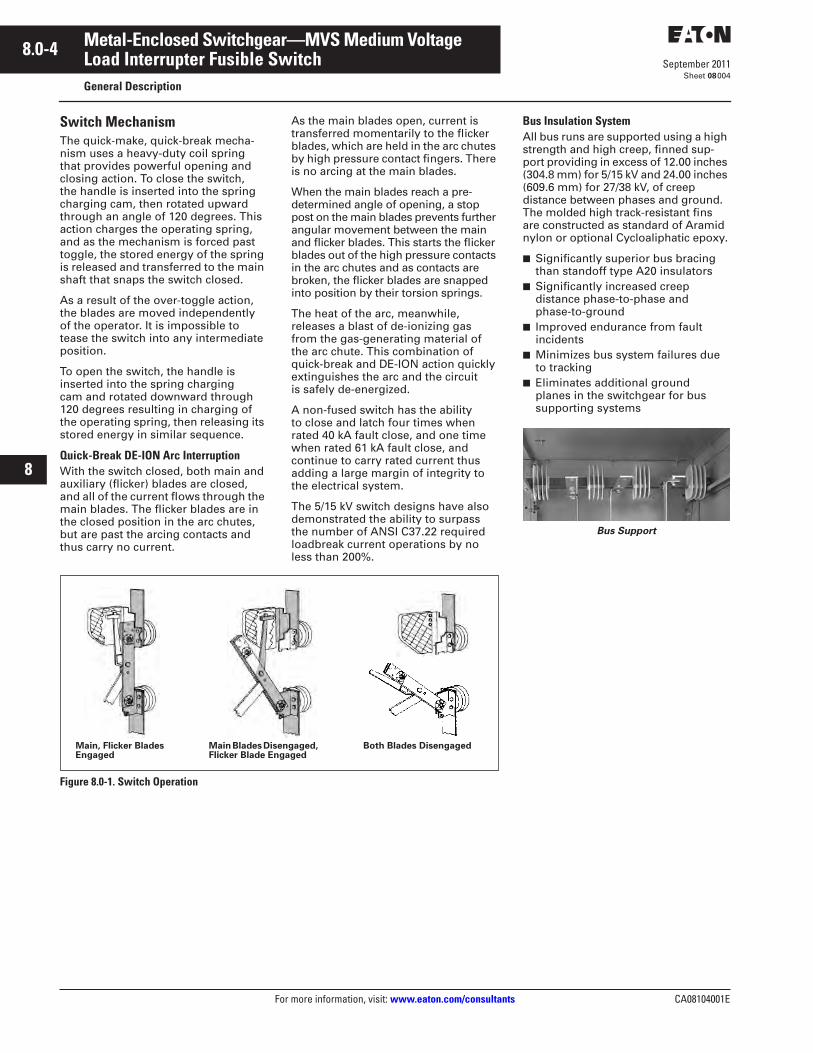
Quick-Break DE-ION Arc Interruption
With the switch closed, both main and auxiliary (flicker) blades are closed, and all of the current flows through the main blades. The flicker blades are in the closed position in the arc chutes, but are past the arcing contacts and thus carry no current.
As the main blades open, current is transferred momentarily to the flicker blades, which are held in the arc chutes by high pressure contact fingers. There is no arcing at the main blades.
When the main blades reach a pre-determined angle of opening, a stop post on the main blades prevents further angular movement between the main and flicker blades. This starts the flicker blades out of the high pressure contacts in the arc chutes and as contacts are broken, the flicker blades are snapped into position by their torsion springs.
The heat of the arc, meanwhile, releases a blast of de-ionizing gas from the gas-generating material of the arc chute. This combination of quick-break and DE-ION action quickly extinguishes the arc and the circuit is safely de-energized.
A non-fused switch has the ability to close and latch four times when rated 40 kA fault close, and one time when rated 61 kA fault close, and continue to carry rated current thus adding a large margin of integrity to the electrical system.
The 5/15 kV switch designs have also demonstrated the ability to surpass the number of ANSI C37.22 required loadbreak current operations by no less than 200%.
Figure 8.0-1. Switch Operation
Both Blades DisengagedMain, Flicker Blades Engaged
Main Blades Disengaged, Flicker Blade Engaged
Bus Insulation System
All bus runs are supported using a high strength and high creep, finned sup-port providing in excess of 12.00 inches (304.8 mm) for 5/15 kV and 24.00 inches (609.6 mm) for 27/38 kV, of creep distance between phases and ground. The molded high track-resistant fins are constructed as standard of Aramid nylon or optional Cycloaliphatic epoxy.
■
Significantly superior bus bracing than standoff type A20 insulators
■
Significantly increased creep distance phase-to-phase and phase-to-ground
■
Improved endurance from fault incidents
■
Minimizes bus system failures due to tracking
■
Eliminates additional ground planes in the switchgear for bus supporting systems
Bus Support
8.0-12
For more information, visit: www.eaton.com/consultants CA08104001E
September 2011
Metal-Enclosed Switchgear—MVS Medium Voltage
i
ii
1
2
3
4
5
6
7
8
9
10
11
12
13
14
15
16
17
18
19
20
21
Sheet 08
Load Interrupter Fusible SwitchTechnical Data
012
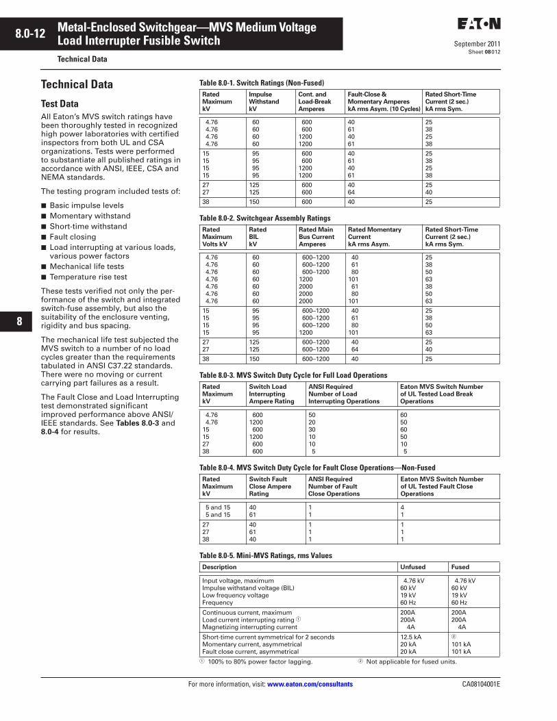
Technical Data
Test DataAll Eaton’s MVS switch ratings have been thoroughly tested in recognized high power laboratories with certified inspectors from both UL and CSA organizations. Tests were performed to substantiate all published ratings in accordance with ANSI, IEEE, CSA and NEMA standards.
The testing program included tests of:
■ Basic impulse levels■ Momentary withstand■ Short-time withstand■ Fault closing■ Load interrupting at various loads,
various power factors■ Mechanical life tests■ Temperature rise test
These tests verified not only the per-formance of the switch and integrated switch-fuse assembly, but also the suitability of the enclosure venting, rigidity and bus spacing.
The mechanical life test subjected the MVS switch to a number of no load cycles greater than the requirements tabulated in ANSI C37.22 standards. There were no moving or current carrying part failures as a result.
The Fault Close and Load Interrupting test demonstrated significant improved performance above ANSI/IEEE standards. See Tables 8.0-3 and8.0-4 for results.
Table 8.0-1. Switch Ratings (Non-Fused)
Table 8.0-2. Switchgear Assembly Ratings
Table 8.0-3. MVS Switch Duty Cycle for Full Load Operations
Table 8.0-4. MVS Switch Duty Cycle for Fault Close Operations—Non-Fused
Table 8.0-5. Mini-MVS Ratings, rms Values
� 100% to 80% power factor lagging. � Not applicable for fused units.
Rated Maximum kV
ImpulseWithstand kV
Cont. andLoad-BreakAmperes
Fault-Close &Momentary Amperes kA rms Asym. (10 Cycles)
Rated Short-TimeCurrent (2 sec.) kA rms Sym.
4.76 4.76 4.76 4.76
60 60 60 60
600 60012001200
40614061
25382538
15151515
95 95 95 95
600 60012001200
40614061
25382538
2727
125125
600 600
4064
2540
38 150 600 40 25
Rated MaximumVolts kV
RatedBILkV
Rated Main Bus Current Amperes
Rated Momentary CurrentkA rms Asym.
Rated Short-Time Current (2 sec.) kA rms Sym.
4.76 4.76 4.76 4.76 4.76 4.76 4.76
60 60 60 60 60 60 60
600–1200 600–1200 600–12001200200020002000
40 61 80101 61 80101
25385063385063
15151515
95 95 95 95
600–1200 600–1200 600–12001200
40 61 80101
25385063
2727
125125
600–1200 600–1200
40 64
2540
38 150 600–1200 40 25
Rated MaximumkV
Switch Load Interrupting Ampere Rating
ANSI Required Number of Load Interrupting Operations
Eaton MVS Switch Number of UL Tested Load Break Operations
4.76 4.7615152738
6001200 6001200 600 600
5020301010 5
6050605010 5
Rated MaximumkV
Switch Fault Close Ampere Rating
ANSI Required Number of Fault Close Operations
Eaton MVS Switch Number of UL Tested Fault Close Operations
5 and 15 5 and 15
4061
11
41
272738
406140
111
111
Description Unfused Fused
Input voltage, maximumImpulse withstand voltage (BIL)Low frequency voltageFrequency
4.76 kV60 kV19 kV60 Hz
4.76 kV60 kV19 kV60 Hz
Continuous current, maximumLoad current interrupting rating �Magnetizing interrupting current
200A200A 4A
200A200A 4A
Short-time current symmetrical for 2 secondsMomentary current, asymmetricalFault close current, asymmetrical
12.5 kA20 kA20 kA
�
101 kA101 kA
CA08104001E For more information, visit: www.eaton.com/consultants
8.0-13September 2011
Metal-Enclosed Switchgear—MVS Medium Voltage
i
ii
1
2
3
4
5
6
7
8
9
10
11
12
13
14
15
16
17
18
19
20
21
Sheet 08
Load Interrupter Fusible SwitchTechnical Data
013
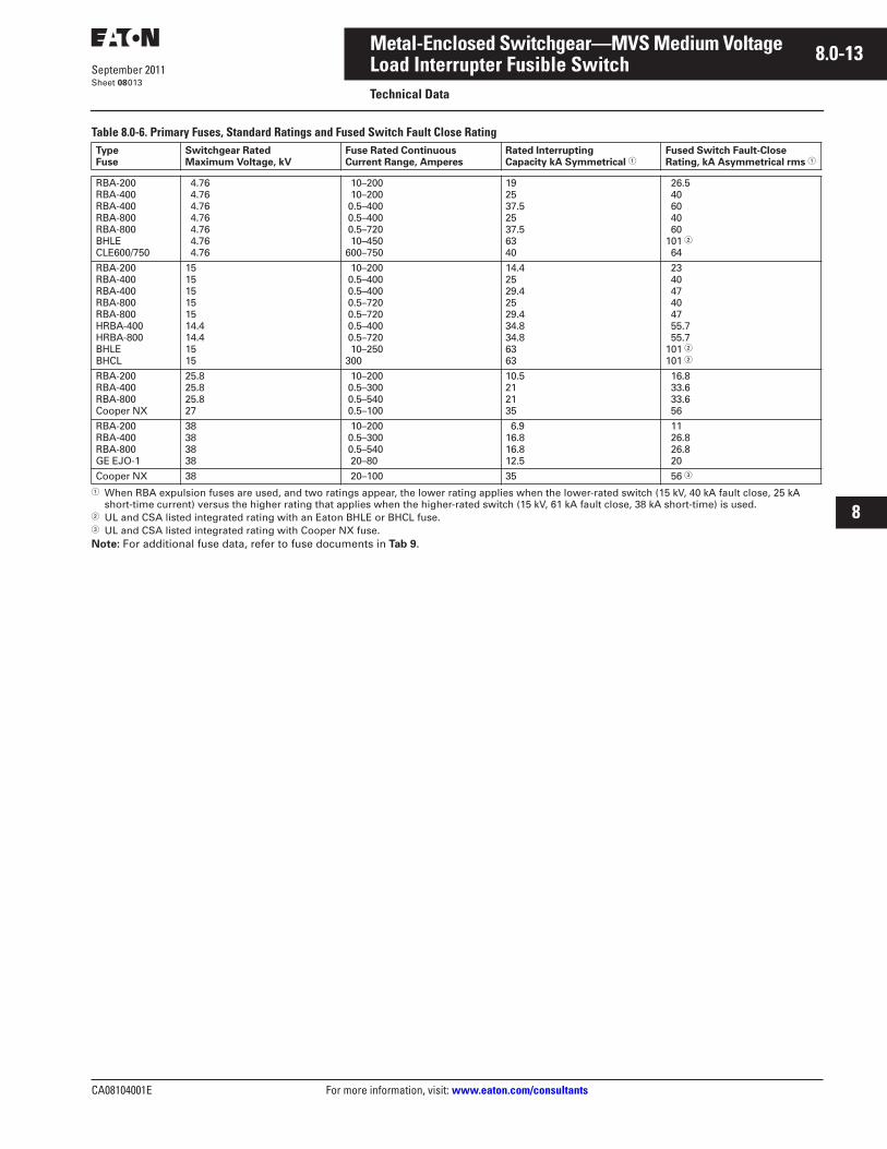
Table 8.0-6. Primary Fuses, Standard Ratings and Fused Switch Fault Close Rating
� When RBA expulsion fuses are used, and two ratings appear, the lower rating applies when the lower-rated switch (15 kV, 40 kA fault close, 25 kA short-time current) versus the higher rating that applies when the higher-rated switch (15 kV, 61 kA fault close, 38 kA short-time) is used.
� UL and CSA listed integrated rating with an Eaton BHLE or BHCL fuse.� UL and CSA listed integrated rating with Cooper NX fuse.Note: For additional fuse data, refer to fuse documents in Tab 9.
Type Fuse
Switchgear Rated Maximum Voltage, kV
Fuse Rated Continuous Current Range, Amperes
Rated Interrupting Capacity kA Symmetrical �
Fused Switch Fault-Close Rating, kA Asymmetrical rms �
RBA-200RBA-400RBA-400RBA-800RBA-800BHLECLE600/750
4.76 4.76 4.76 4.76 4.76 4.76 4.76
10–200 10–200 0.5–400 0.5–400 0.5–720 10–450600–750
192537.52537.56340
26.5 40 60 40 60101 � 64
RBA-200RBA-400RBA-400RBA-800RBA-800HRBA-400HRBA-800BHLEBHCL
151515151514.414.41515
10–200 0.5–400 0.5–400 0.5–720 0.5–720 0.5–400 0.5–720 10–250300
14.42529.42529.434.834.86363
23 40 47 40 47 55.7 55.7101 �101 �
RBA-200RBA-400RBA-800Cooper NX
25.825.825.827
10–200 0.5–300 0.5–540 0.5–100
10.5212135
16.8 33.6 33.6 56
RBA-200RBA-400RBA-800GE EJO-1
38383838
10–200 0.5–300 0.5–540 20–80
6.916.816.812.5
11 26.8 26.8 20
Cooper NX 38 20–100 35 56 �
CA08104001E For more information, visit: www.eaton.com/consultants
8.0-23September 2011
Metal-Enclosed Switchgear—MVS Medium Voltage
i
ii
1
2
3
4
5
6
7
8
9
10
11
12
13
14
15
16
17
18
19
20
21
Sheet 08
Load Interrupter Fusible SwitchLayouts—Dimensions
023
.
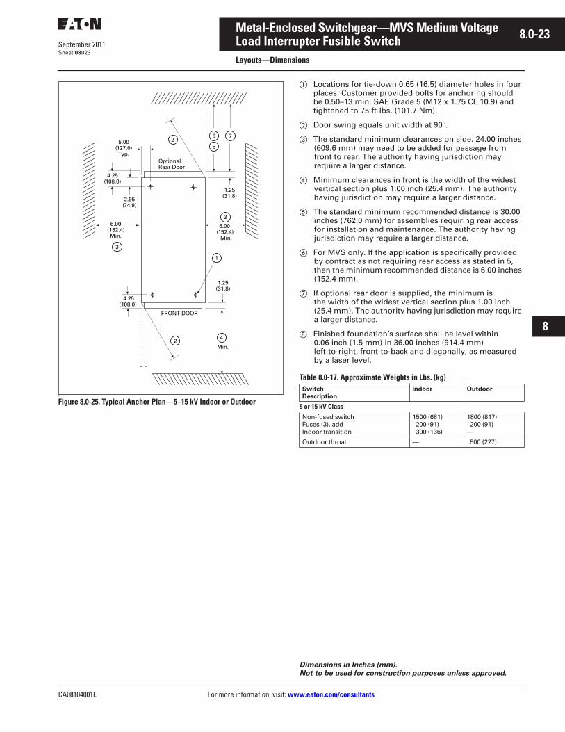
Figure 8.0-25. Typical Anchor Plan—5–15 kV Indoor or Outdoor
� Locations for tie-down 0.65 (16.5) diameter holes in four places. Customer provided bolts for anchoring should be 0.50–13 min. SAE Grade 5 (M12 x 1.75 CL 10.9) and tightened to 75 ft-lbs. (101.7 Nm).
� Door swing equals unit width at 90º.
� The standard minimum clearances on side. 24.00 inches(609.6 mm) may need to be added for passage from front to rear. The authority having jurisdiction may require a larger distance.
� Minimum clearances in front is the width of the widest vertical section plus 1.00 inch (25.4 mm). The authority having jurisdiction may require a larger distance.
� The standard minimum recommended distance is 30.00 inches (762.0 mm) for assemblies requiring rear access for installation and maintenance. The authority having jurisdiction may require a larger distance.
� For MVS only. If the application is specifically provided by contract as not requiring rear access as stated in 5, then the minimum recommended distance is 6.00 inches (152.4 mm).
� If optional rear door is supplied, the minimum is the width of the widest vertical section plus 1.00 inch (25.4 mm). The authority having jurisdiction may require a larger distance.
� Finished foundation’s surface shall be level within 0.06 inch (1.5 mm) in 36.00 inches (914.4 mm) left-to-right, front-to-back and diagonally, as measured by a laser level.
Table 8.0-17. Approximate Weights in Lbs. (kg)
25 7
6
4
1
2Min.
3
5.00(127.0)Typ.
3
6.00(152.4)Min.
FRONT DOOR
Optional Rear Door
4.25(108.0)
6.00(152.4)
Min.
1.25(31.8)
1.25(31.8)
4.25(108.0)
2.95(74.9)
Dimensions in Inches (mm). Not to be used for construction purposes unless approved.
Switch Description
Indoor Outdoor
5 or 15 kV ClassNon-fused switchFuses (3), addIndoor transition
1500 (681) 200 (91) 300 (136)
1800 (817) 200 (91)—
Outdoor throat — 500 (227)
8.0-24
For more information, visit: www.eaton.com/consultants CA08104001E
September 2011
Metal-Enclosed Switchgear—MVS Medium Voltage
i
ii
1
2
3
4
5
6
7
8
9
10
11
12
13
14
15
16
17
18
19
20
21
Sheet 08
Load Interrupter Fusible SwitchLayouts—Dimensions
024
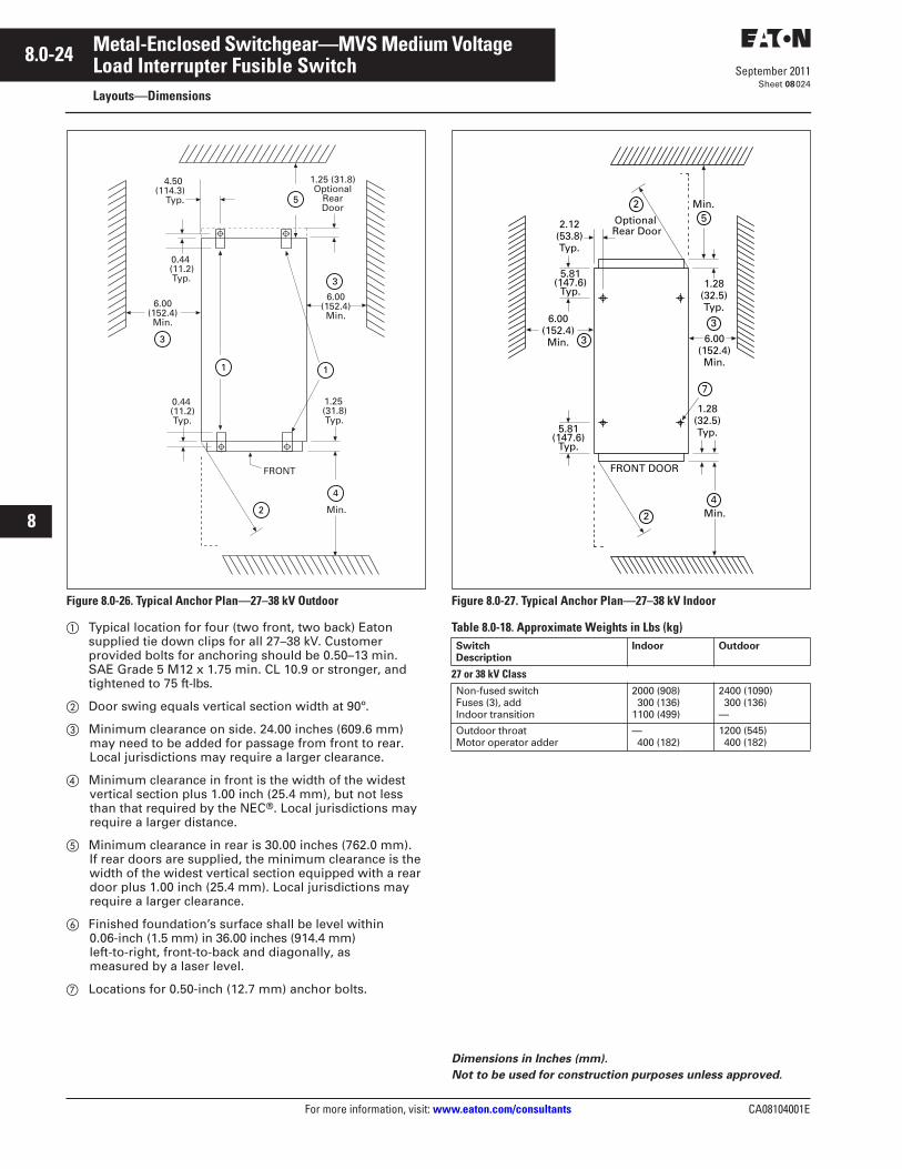
Figure 8.0-26. Typical Anchor Plan—27–38 kV Outdoor
� Typical location for four (two front, two back) Eaton supplied tie down clips for all 27–38 kV. Customer provided bolts for anchoring should be 0.50–13 min. SAE Grade 5 M12 x 1.75 min. CL 10.9 or stronger, and tightened to 75 ft-lbs.
� Door swing equals vertical section width at 90º.
� Minimum clearance on side. 24.00 inches (609.6 mm) may need to be added for passage from front to rear. Local jurisdictions may require a larger clearance.
� Minimum clearance in front is the width of the widest vertical section plus 1.00 inch (25.4 mm), but not less than that required by the NEC®. Local jurisdictions may require a larger distance.
� Minimum clearance in rear is 30.00 inches (762.0 mm). If rear doors are supplied, the minimum clearance is the width of the widest vertical section equipped with a rear door plus 1.00 inch (25.4 mm). Local jurisdictions may require a larger clearance.
� Finished foundation’s surface shall be level within 0.06-inch (1.5 mm) in 36.00 inches (914.4 mm) left-to-right, front-to-back and diagonally, asmeasured by a laser level.
� Locations for 0.50-inch (12.7 mm) anchor bolts.
Figure 8.0-27. Typical Anchor Plan—27–38 kV Indoor
Table 8.0-18. Approximate Weights in Lbs (kg)
4.50 (114.3)
Typ.
FRONT
Min.
1.25 (31.8)Optional
RearDoor
0.44 (11.2)Typ.
6.00(152.4)Min.
6.00(152.4)Min.
0.44 (11.2)Typ.
1.25 (31.8)Typ.
11
2
3
5
4
3
Dimensions in Inches (mm).
Not to be used for construction purposes unless approved.
Switch Description
Indoor Outdoor
27 or 38 kV ClassNon-fused switchFuses (3), addIndoor transition
2000 (908) 300 (136)1100 (499)
2400 (1090) 300 (136)—
Outdoor throatMotor operator adder
— 400 (182)
1200 (545) 400 (182)
2 Min.5
4
7
2 Min.
3
2.12(53.8)Typ.
6.00(152.4)Min.
1.28(32.5)Typ.5.81
(147.6)Typ.
5.81(147.6)
Typ.
3
FRONT DOOR
Optional Rear Door
6.00(152.4)Min.
1.28(32.5)Typ.

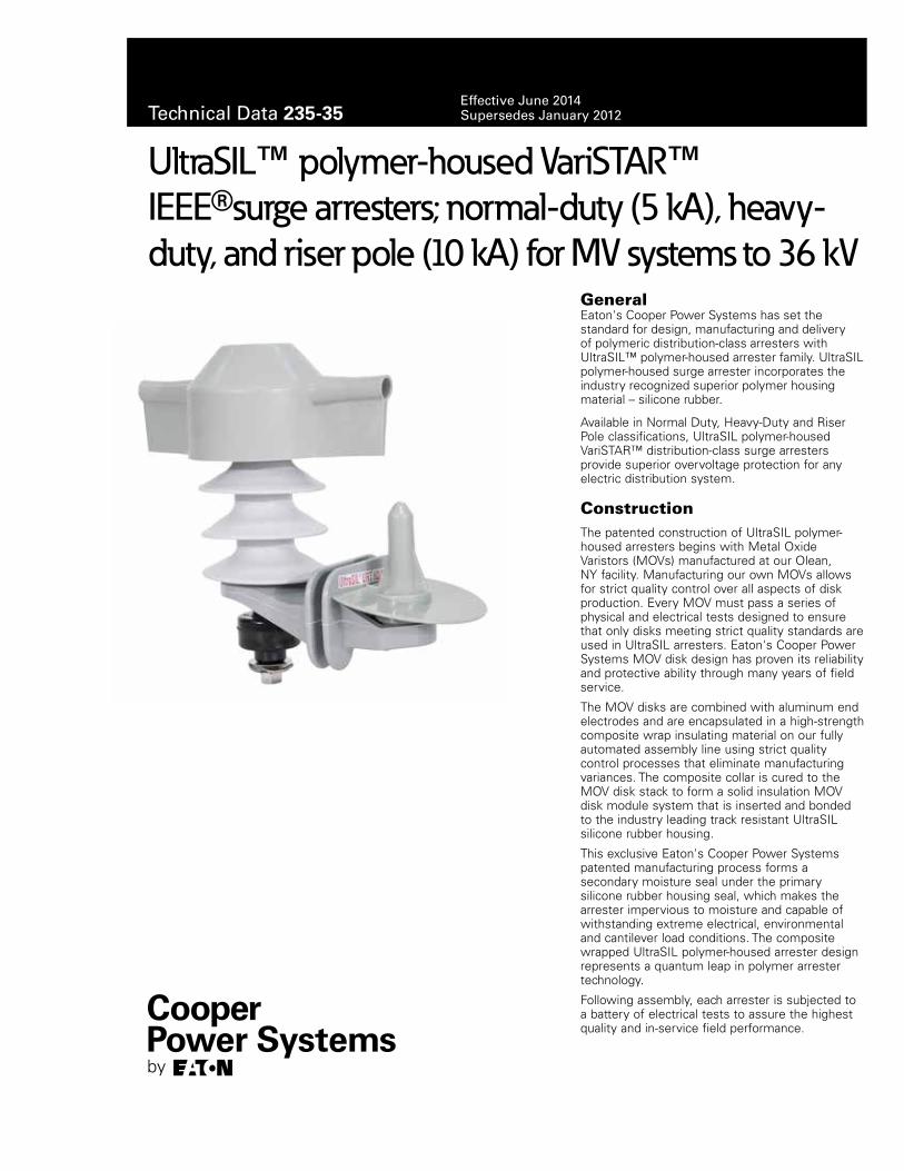
Eaton's Cooper Power Systems has set the standard for design, manufacturing and delivery of polymeric distribution-class arresters with UltraSIL™ polymer-housed arrester family. UltraSIL polymer-housed surge arrester incorporates the industry recognized superior polymer housing material – silicone rubber.
Available in Normal Duty, Heavy-Duty and Riser Pole classifications, UltraSIL polymer-housed VariSTAR™ distribution-class surge arresters provide superior overvoltage protection for any electric distribution system.
ConstructionThe patented construction of UltraSIL polymer-housed arresters begins with Metal Oxide Varistors (MOVs) manufactured at our Olean, NY facility. Manufacturing our own MOVs allows for strict quality control over all aspects of disk production. Every MOV must pass a series of physical and electrical tests designed to ensure that only disks meeting strict quality standards are used in UltraSIL arresters. Eaton's Cooper Power Systems MOV disk design has proven its reliability and protective ability through many years of field service.
The MOV disks are combined with aluminum end electrodes and are encapsulated in a high-strength composite wrap insulating material on our fully automated assembly line using strict quality control processes that eliminate manufacturing variances. The composite collar is cured to the MOV disk stack to form a solid insulation MOV disk module system that is inserted and bonded to the industry leading track resistant UltraSIL silicone rubber housing.
This exclusive Eaton's Cooper Power Systems patented manufacturing process forms a secondary moisture seal under the primary silicone rubber housing seal, which makes the arrester impervious to moisture and capable of withstanding extreme electrical, environmental and cantilever load conditions. The composite wrapped UltraSIL polymer-housed arrester design represents a quantum leap in polymer arrester technology.
Following assembly, each arrester is subjected to a battery of electrical tests to assure the highest quality and in-service field performance.
UltraSIL™ polymer-housed VariSTAR™ IEEE®surge arresters; normal-duty (5 kA), heavy-duty, and riser pole (10 kA) for MV systems to 36 kV
General
Technical Data 235-35Effective June 2014Supersedes January 2012
FeaturesUltraSIL silicone rubber polymer-housing has undergone a wide range of design tests to determine the optimum shed configuration. In addition, long term environmental testing has verified the lifetime superiority of silicone rubber when compared to other polymeric insulating materials.
Independent laboratory tests have verified the superiority of silicone rubber in terms of non-wetting surfaces, resistance to UV degradation and surface tracking, performance in contaminated environments, chemical inertness, temperature stability and other important insulating properties. UltraSIL silicone rubber polymer-housing will not support biological growth (algae and mildew), is non-flammable and will not support combustion.
An optional insulated mounting base is available to allow connecting to a wide variety of brackets. The insulated base, made of glass filled polyester, has been designed to provide needed mechanical strength for installation and severe loading conditions.
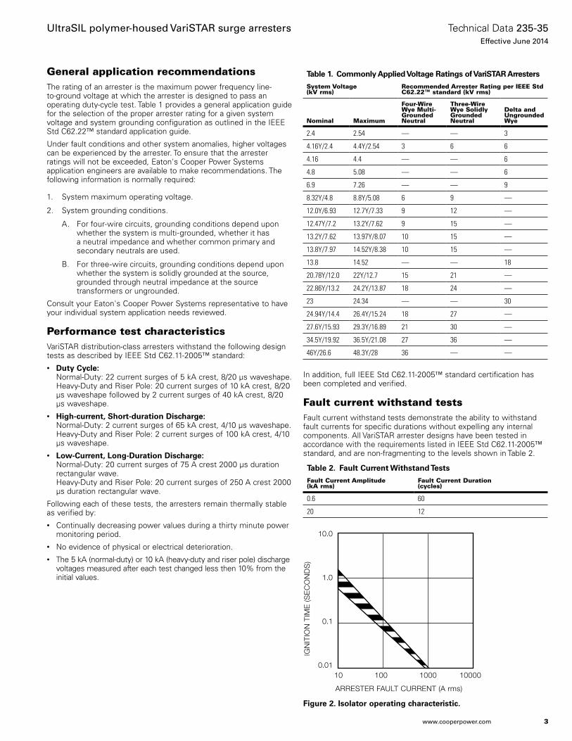
A ground lead isolator is also available. The isolator removes the ground terminal from the arrester in the unlikely event of arrester failure, thus preventing a permanent system fault. An isolator that has operated gives visual indication of internal damage to the arrester and the need for arrester replacement. See Figure 2 for the isolator operating characteristics.
The optional universal wildlife protector has two self-adjusting "valve" style openings which vary from 0 to 0.75" in diameter, thus allowing for a large variety of conductor/insulation sizes while providing optimum wildlife protection. (See page 11, Figure 8 for a dimensional diagram.)
Customers looking to improve system reliability by minimizing wildlife related outages now have multiple options. In addition to the universal wildlife protector featuring two self-adjusting "valve" style openings, Eaton's Cooper Power Systems also offers the more robust line terminal wildlife guard. The line terminal wildlife guard is easily retrofitted to existing arresters installations and provides increased electrical insulation for the high-voltage terminal of the
arrester. The flexible design of the line terminal wildlife guard allows insertion of the lead wire through the bottom of the integral molded flanges. The access holes molded above the flanges will allow conductor sizes ranging from 0 to 0.50” in diameter (OD). The line terminal wildlife guard geometry allows water to shed away from the surface area of the animal guard while minimizing ice build up and maintaining flexibility through extreme operating temperatures. (Refer to page 11, Figure 9 for a dimensional diagram.)
For complete wildlife resistance, the ground terminal wildlife guard can easily be installed alongside the line terminal wildlife guard or universal wildlife protector. The ground terminal wildlife guard is a compact and economical guard that ensures wildlife is unable to come in contact with energized objects while on a grounded surface.(Refer to page 11, Figure 10 for a dimensional diagram.)
OperationThe operation of VariSTAR arresters is typical of gapless metal oxide arresters. During steady state conditions, line-to-ground voltage is applied continuously across the arrester terminals. When surges occur, VariSTAR arresters immediately limits the overvoltage to the required protective level by conducting the surge current to ground. Upon passage of the surge, the arrester returns to its initial state, conducting minimal leakage current.
The protective characteristics of VariSTAR arresters provide excellent overvoltage protection for distribution system equipment. (See page 6 for protective characteristics.)
Design testingThe housing material, internals and hardware work together as a system and must stand up to years of exposure to environmental extremes.
To assure a superior level of performance, both the components and the assembled arrester units have been subjected to a program of testing that accurately simulates years of exposure to actual field conditions. Testing includes:• IEEE Std C62.11-2005™ standard Testing – Full certification to
the performance requirements by an independent laboratory. A certified test report is available under Bulletin Number 95062. Additional reference documents are listed on page 14.
Production testsA complete production test program ensures a quality product. Each metal oxide varistor receives a series of electrical tests. Quality is demonstrated by a series of destructive tests performed on every batch of varistors. Listed are the tests performed on the varistors:• 100% Physical Inspection• 100% Discharge Voltage test• 100% V1mA/cm2
• 100% Leakage Current at 80% of V1mA/cm2 Voltage (Watts Loss)• Batch High-current, Short-duration test• Batch Thermal Stability test• Batch Aging test
Each fully assembled VariSTAR arrester must pass the following production tests:• 100% Physical Inspection• 100% Leakage Current test • 100% Partial Discharge Inception Voltage test
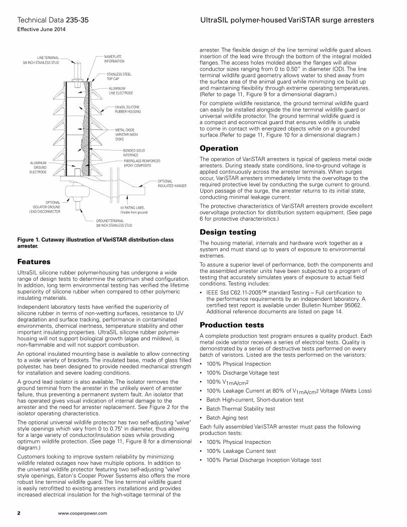
Figure 1. Cutaway illustration of VariSTAR distribution-class arrester.
ALUMINUMLINE ELECTRODE
METAL OXIDEVARISTAR (MOV)DISKS
ALUMINUMGROUND
ELECTRODE
NAMEPLATEINFORMATION
STAINLESS STEELTOP CAP
LINE TERMINAL3/8 INCH STAINLESS STUD
UltraSIL SILICONERUBBER HOUSING
BONDED SOLIDINTERFACE
FIBERGLASS REINFORCEDEPOXY COMPOSITE
OPTIONALINSULATED HANGER
OPTIONALISOLATOR GROUND
LEAD DISCONNECTORkV RATING LABEL(Visible from ground)
GROUND TERMINAL3/8 INCH STAINLESS STUD
2
Technical Data 235-35Effective June 2014
UltraSIL polymer-housed VariSTAR surge arresters
www.cooperpower.com
General application recommendationsThe rating of an arrester is the maximum power frequency line-to-ground voltage at which the arrester is designed to pass an operating duty-cycle test. Table 1 provides a general application guide for the selection of the proper arrester rating for a given system voltage and system grounding configuration as outlined in the IEEE Std C62.22™ standard application guide.
Under fault conditions and other system anomalies, higher voltages can be experienced by the arrester. To ensure that the arrester ratings will not be exceeded, Eaton's Cooper Power Systems application engineers are available to make recommendations. The following information is normally required:
1. System maximum operating voltage.
2. System grounding conditions.
A. For four-wire circuits, grounding conditions depend upon whether the system is multi-grounded, whether it has a neutral impedance and whether common primary and secondary neutrals are used.
B. For three-wire circuits, grounding conditions depend upon whether the system is solidly grounded at the source, grounded through neutral impedance at the source transformers or ungrounded.
Consult your Eaton's Cooper Power Systems representative to have your individual system application needs reviewed.
Performance test characteristicsVariSTAR distribution-class arresters withstand the following design tests as described by IEEE Std C62.11-2005™ standard:• Duty Cycle:
Normal-Duty: 22 current surges of 5 kA crest, 8/20 µs waveshape.Heavy-Duty and Riser Pole: 20 current surges of 10 kA crest, 8/20 µs waveshape followed by 2 current surges of 40 kA crest, 8/20 µs waveshape.
• High-current, Short-duration Discharge: Normal-Duty: 2 current surges of 65 kA crest, 4/10 µs waveshape.Heavy-Duty and Riser Pole: 2 current surges of 100 kA crest, 4/10 µs waveshape.
• Low-Current, Long-Duration Discharge: Normal-Duty: 20 current surges of 75 A crest 2000 µs duration rectangular wave. Heavy-Duty and Riser Pole: 20 current surges of 250 A crest 2000 µs duration rectangular wave.
Following each of these tests, the arresters remain thermally stable as verified by:• Continually decreasing power values during a thirty minute power
monitoring period.• No evidence of physical or electrical deterioration.• The 5 kA (normal-duty) or 10 kA (heavy-duty and riser pole) discharge
voltages measured after each test changed less then 10% from the initial values.
In addition, full IEEE Std C62.11-2005™ standard certification has been completed and verified.
Fault current withstand testsFault current withstand tests demonstrate the ability to withstand fault currents for specific durations without expelling any internal components. All VariSTAR arrester designs have been tested in accordance with the requirements listed in IEEE Std C62.11-2005™ standard, and are non-fragmenting to the levels shown in Table 2.
Table 1. Commonly Applied Voltage Ratings of VariSTAR Arresters
System Voltage (kV rms)
Recommended Arrester Rating per IEEE Std C62.22™ standard (kV rms)
Nominal Maximum
Four-Wire Wye Multi-Grounded Neutral
Three-Wire Wye Solidly Grounded Neutral
Delta and Ungrounded Wye
2.4 2.54 — — 3
4.16Y/2.4 4.4Y/2.54 3 6 6
4.16 4.4 — — 6
4.8 5.08 — — 6
6.9 7.26 — — 9
8.32Y/4.8 8.8Y/5.08 6 9 —
12.0Y/6.93 12.7Y/7.33 9 12 —
12.47Y/7.2 13.2Y/7.62 9 15 —
13.2Y/7.62 13.97Y/8.07 10 15 —
13.8Y/7.97 14.52Y/8.38 10 15 ––
13.8 14.52 — — 18
20.78Y/12.0 22Y/12.7 15 21 —
22.86Y/13.2 24.2Y/13.87 18 24 —
23 24.34 — — 30
24.94Y/14.4 26.4Y/15.24 18 27 —
27.6Y/15.93 29.3Y/16.89 21 30 —
34.5Y/19.92 36.5Y/21.08 27 36 —
46Y/26.6 48.3Y/28 36 — —
Table 2. Fault Current Withstand Tests
Fault Current Amplitude (kA rms)
Fault Current Duration (cycles)
0.6 60
20 12
10.0
1.0
0.1
0.0110 100 1000 10000
ARRESTER FAULT CURRENT (A rms)
IGN
ITIO
N T
IME
(SE
CO
ND
S)
Figure 2. Isolator operating characteristic.
3
Technical Data 235-35Effective June 2014
UltraSIL polymer-housed VariSTAR surge arresters
www.cooperpower.com
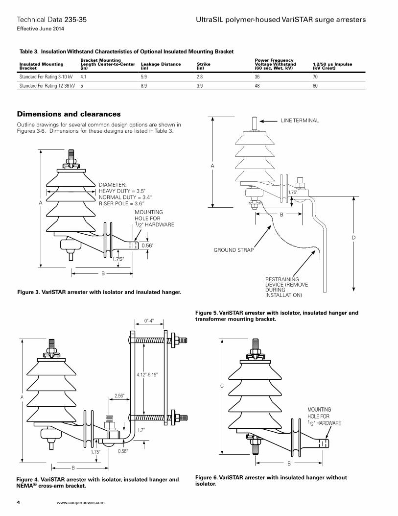
Figure 3. VariSTAR arrester with isolator and insulated hanger.
A
B
DIAMETER:HEAVY DUTY = 3.5"NORMAL DUTY = 3.4”RISER POLE = 3.6”
MOUNTING HOLE FOR 1/2" HARDWARE
0.56"
1.75"
Figure 6. VariSTAR arrester with insulated hanger without isolator.
C
B
MOUNTING HOLE FOR 1/2" HARDWARE
Figure 4. VariSTAR arrester with isolator, insulated hanger and NEMA® cross-arm bracket.
A
0.56"
2.56"
1.7"
4.12"-5.15"
B
0"-4"
1.75"
Dimensions and clearancesOutline drawings for several common design options are shown in Figures 3-6. Dimensions for these designs are listed in Table 3.
Figure 5. VariSTAR arrester with isolator, insulated hanger and transformer mounting bracket.
GROUND STRAP
LINE TERMINAL
RESTRAINING DEVICE (REMOVE DURING INSTALLATION)
D
A
B
1.75"
Table 3. Insulation Withstand Characteristics of Optional Insulated Mounting Bracket
Insulated Mounting Bracket
Bracket Mounting Length Center-to-Center (in)
Leakage Distance(in)
Strike (in)
Power Frequency Voltage Withstand (60 sec, Wet, kV)
1.2/50 μs Impulse (kV Crest)
Standard For Rating 3-10 kV 4.1 5.9 2.8 36 70
Standard For Rating 12-36 kV 5 8.9 3.9 48 80
4
Technical Data 235-35Effective June 2014
UltraSIL polymer-housed VariSTAR surge arresters
www.cooperpower.com
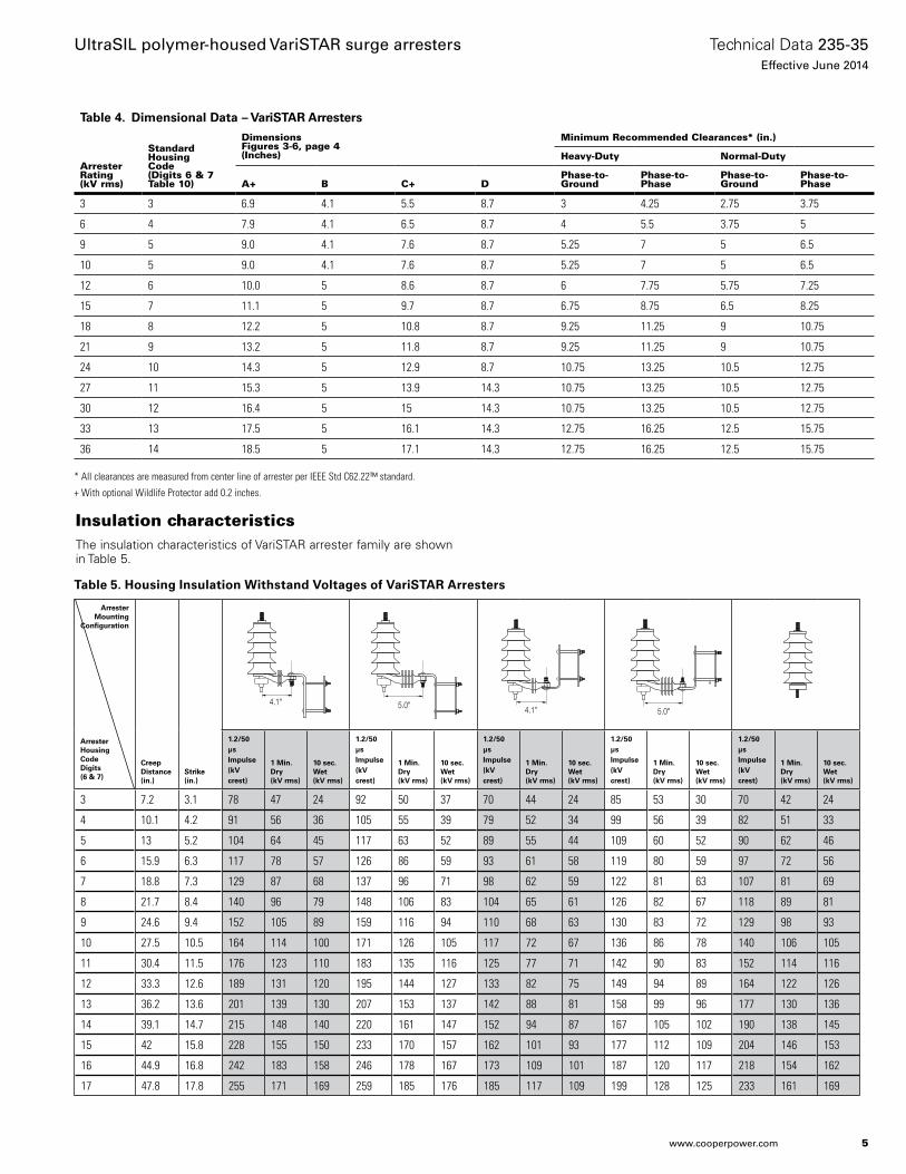
Table 5. Housing Insulation Withstand Voltages of VariSTAR Arresters
Insulation characteristicsThe insulation characteristics of VariSTAR arrester family are shown in Table 5.
Table 4. Dimensional Data – VariSTAR Arresters
Arrester Rating (kV rms)
Standard HousingCode (Digits 6 & 7Table 10)
DimensionsFigures 3-6, page 4 (Inches)
Minimum Recommended Clearances* (in.)
Heavy-Duty Normal-Duty
A+ B C+ DPhase-to-Ground
Phase-to-Phase
Phase-to-Ground
Phase-to-Phase
3 3 6.9 4.1 5.5 8.7 3 4.25 2.75 3.75
6 4 7.9 4.1 6.5 8.7 4 5.5 3.75 5
9 5 9.0 4.1 7.6 8.7 5.25 7 5 6.5
10 5 9.0 4.1 7.6 8.7 5.25 7 5 6.5
12 6 10.0 5 8.6 8.7 6 7.75 5.75 7.25
15 7 11.1 5 9.7 8.7 6.75 8.75 6.5 8.25
18 8 12.2 5 10.8 8.7 9.25 11.25 9 10.75
21 9 13.2 5 11.8 8.7 9.25 11.25 9 10.75
24 10 14.3 5 12.9 8.7 10.75 13.25 10.5 12.75
27 11 15.3 5 13.9 14.3 10.75 13.25 10.5 12.75
30 12 16.4 5 15 14.3 10.75 13.25 10.5 12.75
33 13 17.5 5 16.1 14.3 12.75 16.25 12.5 15.75
36 14 18.5 5 17.1 14.3 12.75 16.25 12.5 15.75
ArresterMounting
Configuration
ArresterHousingCodeDigits (6 & 7)
Creep Distance (in.)
Strike(in.)
4.1" 5.0" 4.1" 5.0"
1.2/50 µs Impulse(kV crest)
1 Min. Dry(kV rms)
10 sec.Wet(kV rms)
1.2/50 µs Impulse(kV crest)
1 Min. Dry(kV rms)
10 sec.Wet(kV rms)
1.2/50 µs Impulse(kV crest)
1 Min. Dry(kV rms)
10 sec.Wet(kV rms)
1.2/50 µs Impulse(kV crest)
1 Min. Dry(kV rms)
10 sec.Wet(kV rms)
1.2/50 µs Impulse(kV crest)
1 Min. Dry(kV rms)
10 sec.Wet(kV rms)
3 7.2 3.1 78 47 24 92 50 37 70 44 24 85 53 30 70 42 24
4 10.1 4.2 91 56 36 105 55 39 79 52 34 99 56 39 82 51 33
5 13 5.2 104 64 45 117 63 52 89 55 44 109 60 52 90 62 46
6 15.9 6.3 117 78 57 126 86 59 93 61 58 119 80 59 97 72 56
7 18.8 7.3 129 87 68 137 96 71 98 62 59 122 81 63 107 81 69
8 21.7 8.4 140 96 79 148 106 83 104 65 61 126 82 67 118 89 81
9 24.6 9.4 152 105 89 159 116 94 110 68 63 130 83 72 129 98 93
10 27.5 10.5 164 114 100 171 126 105 117 72 67 136 86 78 140 106 105
11 30.4 11.5 176 123 110 183 135 116 125 77 71 142 90 83 152 114 116
12 33.3 12.6 189 131 120 195 144 127 133 82 75 149 94 89 164 122 126
13 36.2 13.6 201 139 130 207 153 137 142 88 81 158 99 96 177 130 136
14 39.1 14.7 215 148 140 220 161 147 152 94 87 167 105 102 190 138 145
15 42 15.8 228 155 150 233 170 157 162 101 93 177 112 109 204 146 153
16 44.9 16.8 242 183 158 246 178 167 173 109 101 187 120 117 218 154 162
17 47.8 17.8 255 171 169 259 185 176 185 117 109 199 128 125 233 161 169
* All clearances are measured from center line of arrester per IEEE Std C62.22™ standard.
+ With optional Wildlife Protector add 0.2 inches.
5
Technical Data 235-35Effective June 2014
UltraSIL polymer-housed VariSTAR surge arresters
www.cooperpower.com
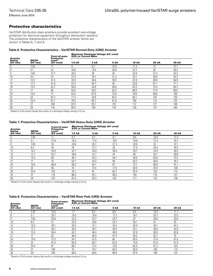
Protective characteristicsVariSTAR distribution-class arresters provide excellent overvoltage protection for electrical equipment throughout distribution systems. The protective characteristics of the VariSTAR arrester family are shown in Tables 6, 7, and 8.
Table 6. Protective Characteristics – VariSTAR Normal-Duty (UNS) Arrester
Arrester Rating (kV rms)
MCOV (kV rms)
Front-of-wave Protective Level* (kV crest)
Maximum Discharge Voltage (kV crest) 8/20 µs Current Wave
1.5 kA 3 kA 5 kA 10 kA 20 kA 40 kA
3 2.55 11 9 9.7 10.4 11.4 13 15.16 5.1 22 18.0 19.4 20.8 22.7 26 30.29 7.65 31.7 26.0 28 30 32.8 37.4 43.510 8.4 33 27.0 29.1 31.2 34.1 38.9 45.312 10.2 41.5 33.9 36.6 39.2 42.9 48.9 56.915 12.7 51.8 42.4 45.7 49 53.6 61.1 71.118 15.3 62.2 50.9 54.9 58.8 64.3 73.4 85.321 17 66 54.0 58.2 62.4 68.2 77.9 90.624 19.5 77 63.0 67.9 72.8 79.6 90.8 10627 22 87.2 71.4 76.9 82.4 90.1 103 12030 24.4 97.1 79.5 85.7 91.8 100 115 13333 27 108 87.8 95.1 102 112 127 14836 29 116 95.3 103 110 120 137 160*Based on 5 kA current impulse that results in a discharge voltage cresting in 0.5 µs.
Table 7. Protective Characteristics – VariSTAR Heavy-Duty (UHS) Arrester
Arrester Rating (kV rms)
MCOV (kV rms)
Front-of-wave Protective Level* (kV crest)
Maximum Discharge Voltage (kV crest) 8/20 µs Current Wave
1.5 kA 3 kA 5 kA 10 kA 20 kA 40 kA
3 2.55 11 8.2 8.7 9.1 9.9 10.9 12.36 5.1 21.9 16.3 17.4 18.2 19.8 21.9 24.79 7.65 33 24.6 26.1 27.3 29.8 33 37.110 8.4 35 26 27.7 29 31.6 34.9 39.412 10.2 43.9 32.7 34.8 36.4 39.7 43.9 49.515 12.7 53.1 39.6 42.1 44 48 53.1 59.818 15.3 66 49.1 52.3 54.7 59.6 65.9 74.221 17 70 52.1 55.4 58 63.2 69.9 78.724 19.5 80.9 60.2 64.1 67 73.1 80.8 91.127 22 94 70 74.5 77.9 84.9 93.9 10630 24.4 102 76.1 81 84.7 92.4 102 11533 27 116 86.5 92.1 96.3 105 116 13136 29 123 91.5 97.3 102 111 123 138*Based on 10 kA current impulse that results in a discharge voltage cresting in 0.5 µs.
Table 8. Protective Characteristics – VariSTAR Riser Pole (URS) Arrester
Arrester Rating (kV rms)
MCOV (kV rms)
Front-of-wave Protective Level* (kV crest)
Maximum Discharge Voltage (kV crest) 8/20 µs Current Wave
1.5 kA 3 kA 5 kA 10 kA 20 kA 40 kA
3 2.55 10.3 7.7 8.2 8.6 9.4 10.3 11.76 5.1 20.7 15.5 16.4 17.2 18.7 20.7 23.39 7.65 29.8 22.3 23.7 24.7 27 29.8 33.610 8.4 31 23.2 24.6 25.7 28.1 31 3512 10.2 39.1 29.2 31.1 32.4 35.4 39.1 44.115 12.7 48.7 36.4 38.7 40.4 44.1 48.8 54.918 15.3 58.4 43.7 46.4 48.5 52.9 58.5 65.921 17 62 46.4 49.3 51.5 56.2 62.1 7024 19.5 72.3 54.1 57.5 60 65.5 72.4 81.627 22 81.4 60.9 64.7 67.6 73.8 81.6 91.930 24.4 91 68.1 72.4 75.6 82.5 91.2 10333 27 100 75 79.7 83.3 90.9 100 11336 29 108 80.6 85.6 89.4 97.6 108 122*Based on 10 kA current impulse that results in a discharge voltage cresting in 0.5 µs.
6
Technical Data 235-35Effective June 2014
UltraSIL polymer-housed VariSTAR surge arresters
www.cooperpower.com
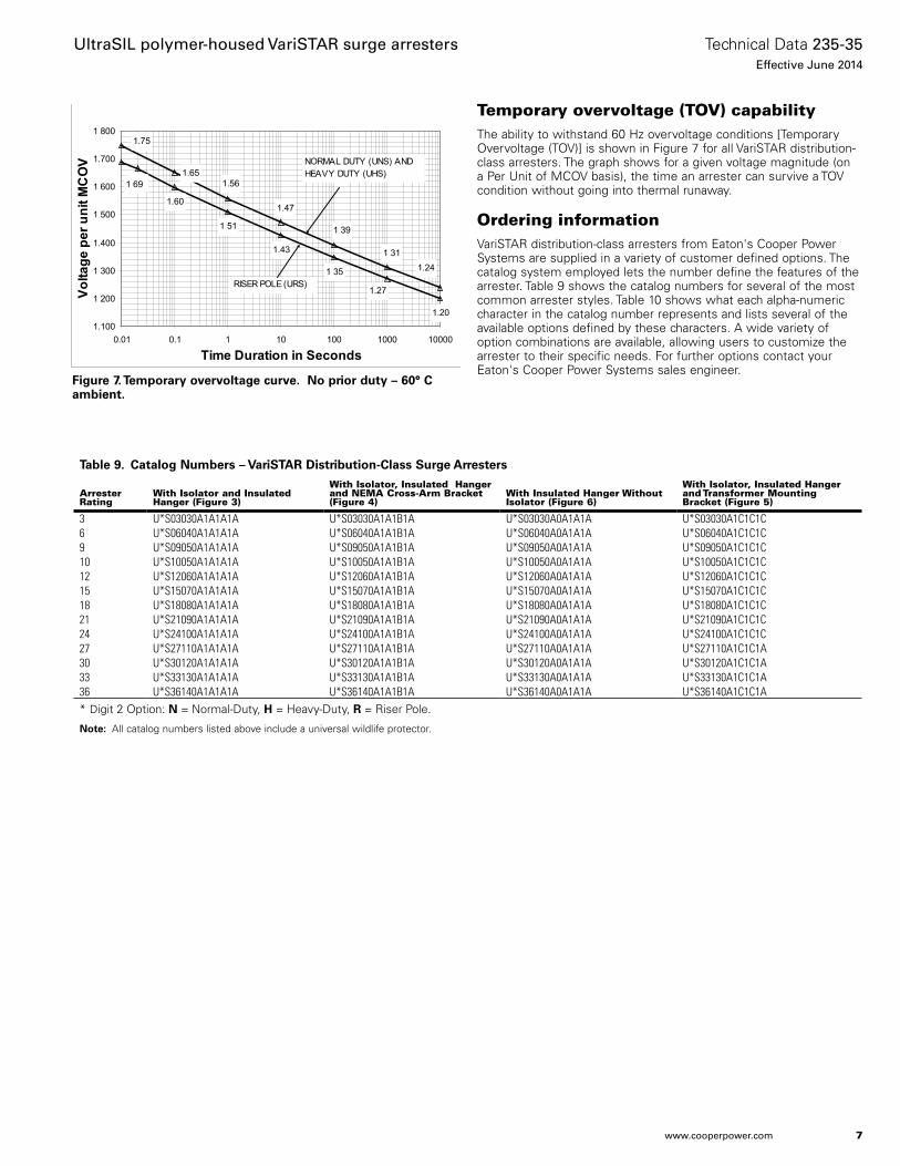
Figure 7. Temporary overvoltage curve. No prior duty – 60° C ambient.
1.60
1 51
1.43
1 35
1.20
1.241 31
1 39
1.47
1.561.65
1.75
1 69
1.27
1.100
1 200
1 300
1.400
1 500
1 600
1.700
1 800
0.01 0.1 1 10 100 1000 10000
Time Duration in Seconds
Volta
ge p
er u
nit M
CO
V
RISER POLE (URS)
NORMAL DUTY (UNS) AND HEAVY DUTY (UHS)
Temporary overvoltage (TOV) capabilityThe ability to withstand 60 Hz overvoltage conditions [Temporary Overvoltage (TOV)] is shown in Figure 7 for all VariSTAR distribution-class arresters. The graph shows for a given voltage magnitude (on a Per Unit of MCOV basis), the time an arrester can survive a TOV condition without going into thermal runaway.
Ordering informationVariSTAR distribution-class arresters from Eaton's Cooper Power Systems are supplied in a variety of customer defined options. The catalog system employed lets the number define the features of the arrester. Table 9 shows the catalog numbers for several of the most common arrester styles. Table 10 shows what each alpha-numeric character in the catalog number represents and lists several of the available options defined by these characters. A wide variety of option combinations are available, allowing users to customize the arrester to their specific needs. For further options contact your Eaton's Cooper Power Systems sales engineer.
Table 9. Catalog Numbers – VariSTAR Distribution-Class Surge Arresters
Arrester Rating
With Isolator and Insulated Hanger (Figure 3)
With Isolator, Insulated Hanger and NEMA Cross-Arm Bracket (Figure 4)
With Insulated Hanger Without Isolator (Figure 6)
With Isolator, Insulated Hanger and Transformer Mounting Bracket (Figure 5)
3 U*S03030A1A1A1A U*S03030A1A1B1A U*S03030A0A1A1A U*S03030A1C1C1C6 U*S06040A1A1A1A U*S06040A1A1B1A U*S06040A0A1A1A U*S06040A1C1C1C9 U*S09050A1A1A1A U*S09050A1A1B1A U*S09050A0A1A1A U*S09050A1C1C1C10 U*S10050A1A1A1A U*S10050A1A1B1A U*S10050A0A1A1A U*S10050A1C1C1C12 U*S12060A1A1A1A U*S12060A1A1B1A U*S12060A0A1A1A U*S12060A1C1C1C15 U*S15070A1A1A1A U*S15070A1A1B1A U*S15070A0A1A1A U*S15070A1C1C1C18 U*S18080A1A1A1A U*S18080A1A1B1A U*S18080A0A1A1A U*S18080A1C1C1C21 U*S21090A1A1A1A U*S21090A1A1B1A U*S21090A0A1A1A U*S21090A1C1C1C24 U*S24100A1A1A1A U*S24100A1A1B1A U*S24100A0A1A1A U*S24100A1C1C1C27 U*S27110A1A1A1A U*S27110A1A1B1A U*S27110A0A1A1A U*S27110A1C1C1A30 U*S30120A1A1A1A U*S30120A1A1B1A U*S30120A0A1A1A U*S30120A1C1C1A33 U*S33130A1A1A1A U*S33130A1A1B1A U*S33130A0A1A1A U*S33130A1C1C1A36 U*S36140A1A1A1A U*S36140A1A1B1A U*S36140A0A1A1A U*S36140A1C1C1A* Digit 2 Option: N = Normal-Duty, H = Heavy-Duty, R = Riser Pole.
ote:N All catalog numbers listed above include a universal wildlife protector.
7
Technical Data 235-35Effective June 2014
UltraSIL polymer-housed VariSTAR surge arresters
www.cooperpower.com
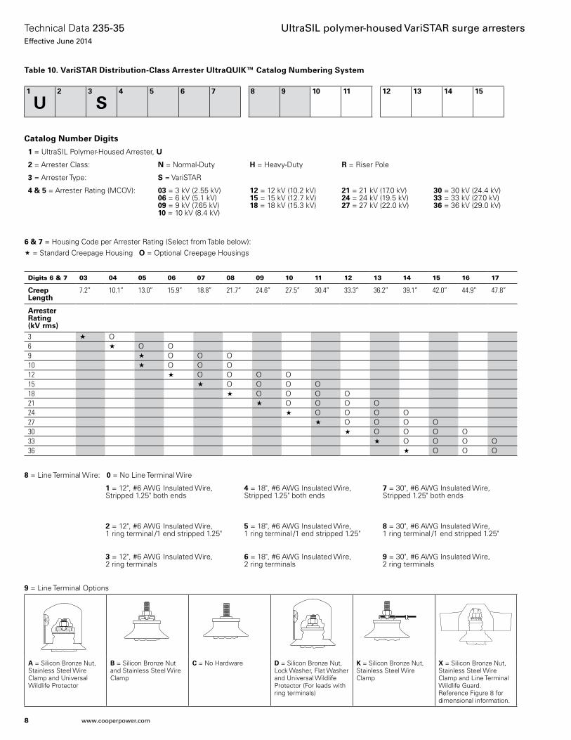
8 = Line Terminal Wire: 0 = No Line Terminal Wire
1 = 12", #6 AWG Insulated Wire, Stripped 1.25" both ends
4 = 18", #6 AWG Insulated Wire, Stripped 1.25" both ends
7 = 30", #6 AWG Insulated Wire,Stripped 1.25" both ends
2 = 12", #6 AWG Insulated Wire, 1 ring terminal /1 end stripped 1.25"
5 = 18", #6 AWG Insulated Wire, 1 ring terminal /1 end stripped 1.25"
8 = 30", #6 AWG Insulated Wire, 1 ring terminal /1 end stripped 1.25"
3 = 12", #6 AWG Insulated Wire, 2 ring terminals
6 = 18", #6 AWG Insulated Wire,2 ring terminals
9 = 30", #6 AWG Insulated Wire, 2 ring terminals
Table 10. VariSTAR Distribution-Class Arrester UltraQUIK™ Catalog Numbering System
Catalog Number Digits
1 = UltraSIL Polymer-Housed Arrester, U
2 = Arrester Class: N = Normal-Duty H = Heavy-Duty R = Riser Pole
3 = Arrester Type: S = VariSTAR
4 & 5 = Arrester Rating (MCOV): 03 = 3 kV (2.55 kV) 06 = 6 kV (5.1 kV)09 = 9 kV (7.65 kV) 10 = 10 kV (8.4 kV)
12 = 12 kV (10.2 kV) 15 = 15 kV (12.7 kV)18 = 18 kV (15.3 kV)
21 = 21 kV (17.0 kV)24 = 24 kV (19.5 kV)27 = 27 kV (22.0 kV)
30 = 30 kV (24.4 kV)33 = 33 kV (27.0 kV)36 = 36 kV (29.0 kV)
9 = Line Terminal Options
A = Silicon Bronze Nut, Stainless Steel Wire Clamp and Universal Wildlife Protector
B = Silicon Bronze Nut and Stainless Steel Wire Clamp
C = No Hardware D = Silicon Bronze Nut, Lock Washer, Flat Washer and Universal Wildlife Protector (For leads with ring terminals)
K = Silicon Bronze Nut, Stainless Steel Wire Clamp
X = Silicon Bronze Nut, Stainless Steel Wire Clamp and Line Terminal Wildlife Guard. Reference Figure 8 for dimensional information.
Digits 6 & 7 03 04 05 06 07 08 09 10 11 12 13 14 15 16 17
Creep Length
7.2” 10.1” 13.0” 15.9” 18.8” 21.7” 24.6” 27.5” 30.4” 33.3” 36.2” 39.1” 42.0” 44.9” 47.8”
Arrester Rating (kV rms)3 « O6 « O O9 « O O O10 « O O O12 « O O O O15 « O O O O18 « O O O O21 « O O O O24 « O O O O27 « O O O O30 « O O O O33 « O O O O36 « O O O
6 & 7 = Housing Code per Arrester Rating (Select from Table below):« = Standard Creepage Housing O = Optional Creepage Housings
1
U2 3
S4 5 6 7 8 9 10 11 12 13 14 15
8
Technical Data 235-35Effective June 2014
UltraSIL polymer-housed VariSTAR surge arresters
www.cooperpower.com
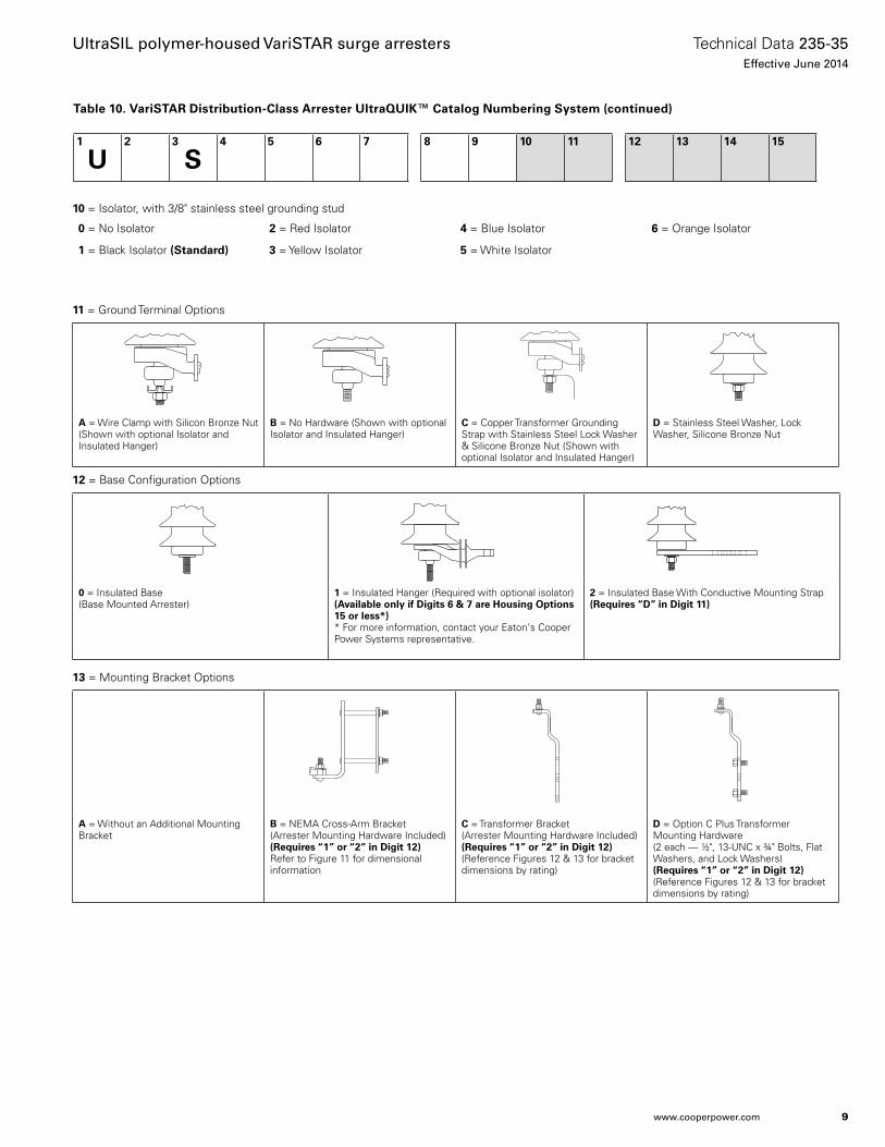
10 = Isolator, with 3/8" stainless steel grounding stud
0 = No Isolator 2 = Red Isolator 4 = Blue Isolator 6 = Orange Isolator
1 = Black Isolator (Standard) 3 = Yellow Isolator 5 = White Isolator
11 = Ground Terminal Options
A = Wire Clamp with Silicon Bronze Nut (Shown with optional Isolator and Insulated Hanger)
B = No Hardware (Shown with optional Isolator and Insulated Hanger)
C = Copper Transformer Grounding Strap with Stainless Steel Lock Washer & Silicone Bronze Nut (Shown with optional Isolator and Insulated Hanger)
D = Stainless Steel Washer, Lock Washer, Silicone Bronze Nut
13 = Mounting Bracket Options
A = Without an Additional Mounting Bracket
B = NEMA Cross-Arm Bracket (Arrester Mounting Hardware Included) (Requires “1” or “2” in Digit 12) Refer to Figure 11 for dimensional information
C = Transformer Bracket(Arrester Mounting Hardware Included)(Requires “1” or “2” in Digit 12)(Reference Figures 12 & 13 for bracket dimensions by rating)
D = Option C Plus Transformer Mounting Hardware(2 each — 1/2", 13-UNC x 3/4" Bolts, Flat Washers, and Lock Washers)(Requires “1” or “2” in Digit 12)(Reference Figures 12 & 13 for bracket dimensions by rating)
12 = Base Configuration Options
0 = Insulated Base(Base Mounted Arrester)
1 = Insulated Hanger (Required with optional isolator)(Available only if Digits 6 & 7 are Housing Options 15 or less*)* For more information, contact your Eaton's Cooper Power Systems representative.
2 = Insulated Base With Conductive Mounting Strap(Requires “D” in Digit 11)
Table 10. VariSTAR Distribution-Class Arrester UltraQUIK™ Catalog Numbering System (continued)
1
U2 3
S4 5 6 7 8 9 10 11 12 13 14 15
9
Technical Data 235-35Effective June 2014
UltraSIL polymer-housed VariSTAR surge arresters
www.cooperpower.com
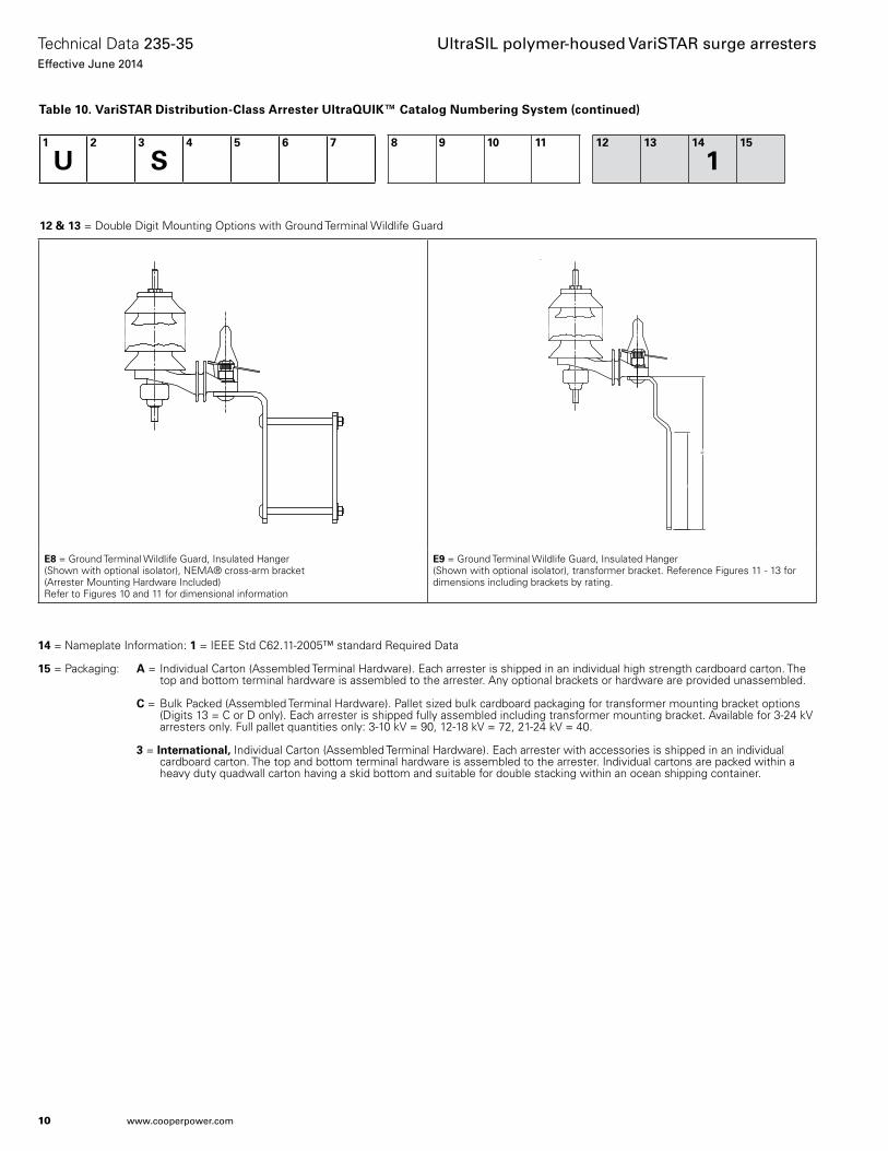
14 = Nameplate Information: 1 = IEEE Std C62.11-2005™ standard Required Data
15 = Packaging: A = Individual Carton (Assembled Terminal Hardware). Each arrester is shipped in an individual high strength cardboard carton. The top and bottom terminal hardware is assembled to the arrester. Any optional brackets or hardware are provided unassembled.
C = Bulk Packed (Assembled Terminal Hardware). Pallet sized bulk cardboard packaging for transformer mounting bracket options (Digits 13 = C or D only). Each arrester is shipped fully assembled including transformer mounting bracket. Available for 3-24 kV arresters only. Full pallet quantities only: 3-10 kV = 90, 12-18 kV = 72, 21-24 kV = 40.
3 = International, Individual Carton (Assembled Terminal Hardware). Each arrester with accessories is shipped in an individual cardboard carton. The top and bottom terminal hardware is assembled to the arrester. Individual cartons are packed within a heavy duty quadwall carton having a skid bottom and suitable for double stacking within an ocean shipping container.
Table 10. VariSTAR Distribution-Class Arrester UltraQUIK™ Catalog Numbering System (continued)
1
U2 3
S4 5 6 7 8 9 10 11 12 13 14
115
12 & 13 = Double Digit Mounting Options with Ground Terminal Wildlife Guard
E8 = Ground Terminal Wildlife Guard, Insulated Hanger(Shown with optional isolator), NEMA® cross-arm bracket (Arrester Mounting Hardware Included)Refer to Figures 10 and 11 for dimensional information
E9 = Ground Terminal Wildlife Guard, Insulated Hanger (Shown with optional isolator), transformer bracket. Reference Figures 11 - 13 for dimensions including brackets by rating.
10
Technical Data 235-35Effective June 2014
UltraSIL polymer-housed VariSTAR surge arresters
www.cooperpower.com
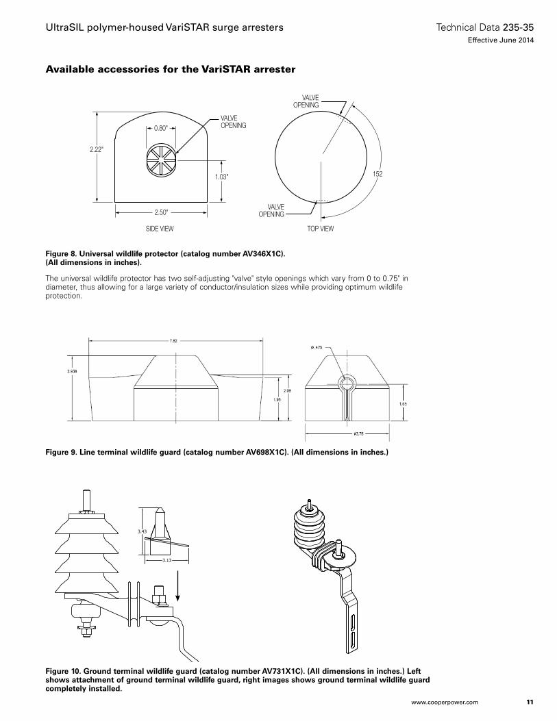
Figure 8. Universal wildlife protector (catalog number AV346X1C). (All dimensions in inches).
The universal wildlife protector has two self-adjusting "valve" style openings which vary from 0 to 0.75" in diameter, thus allowing for a large variety of conductor/insulation sizes while providing optimum wildlife protection.
Available accessories for the VariSTAR arrester
0.80"
2.50"
1.03"
2.22"
VALVEOPENING
VALVEOPENING
VALVEOPENING
SIDE VIEW TOP VIEW
152
Figure 9. Line terminal wildlife guard (catalog number AV698X1C). (All dimensions in inches.)
Figure 10. Ground terminal wildlife guard (catalog number AV731X1C). (All dimensions in inches.) Left shows attachment of ground terminal wildlife guard, right images shows ground terminal wildlife guard completely installed.
11
Technical Data 235-35Effective June 2014
UltraSIL polymer-housed VariSTAR surge arresters
www.cooperpower.com
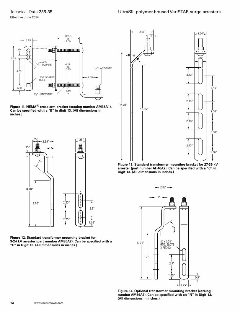
Figure 11. NEMA® cross-arm bracket (catalog number AM35A1). Can be specified with a "B" in digit 13. (All dimensions in inches.)
Figure 12. Standard transformer mounting bracket for 3-24 kV arrester (part number AM36A2). Can be specified with a “C” in Digit 13. (All dimensions in inches.)
2.38"
.25"
.75"
1"
8.70"
5.70"
1.63"
2.25"
50
2.5"
2.25"
1.25"
Figure 13. Standard transformer mounting bracket for 27-36 kV arrester (part number AH46A2). Can be specified with a “C” in Digit 13. (All dimensions in inches.)
3.00”.75”
45°
14.25”
12.55”
2.13”
2.13”
2.13”
2.13”
.56”
3.40”
2.50”
3.38”
1.86”
1.50”
Figure 14. Optional transformer mounting bracket (catalog number AM36A3). Can be specified with an “N” in Digit 13. (All dimensions in inches.)
2.38"
1"
12.25"
7"
1.63"
2.5"
40
0.5"
.56 x 2.25"MTG. SLOTS(2 REQ'D)
1.25"
ZEROTo
4.00
4.12 To
5.15
6.75
2.56
4.50
.344
1.25
.438SQUARE
.438 SQUAREHOLE
.5001.50
3/8" HARDWARE
1/2" HARDWARE
12
Technical Data 235-35Effective June 2014
UltraSIL polymer-housed VariSTAR surge arresters
www.cooperpower.com
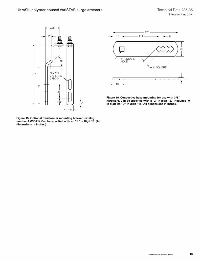
Figure 15. Optional transformer mounting bracket (catalog number AM36A1). Can be specified with an “S” in Digit 13. (All dimensions in inches.)
2.38"
1"
11"
7"
1.63"
2.5"
40
0.5"
.56 x 2.25"MTG. SLOTS(2 REQ'D)
1.5"
114
11 SQUARE
11 SQUAREHOLE
13
13
8
170
9
32
Figure 16. Conductive base mounting for use with 3/8" hardware. Can be specified with a "2" in digit 12. (Requires "0" in digit 10, "D" in digit 11). (All dimensions in inches.)
13
Technical Data 235-35Effective June 2014
UltraSIL polymer-housed VariSTAR surge arresters
www.cooperpower.com

Additional information• S235-35-1, ANSI® IEEE® UltraSIL Housed Distribution-Class MOV
Arrester Installation Instructions• S235-35-2, ANSI® IEEE® UltraSIL Housed Distribution-Class MOV
BPL Coupler Installation• S235-35-3, ANSI® IEEE® UltraSIL Housed Distribution-Class MOV
BPL Coupler Installation Instructions• 95062, ANSI® IEEE ® UltraSIL Polymer-Housed VariSTAR Normal-
Duty, Heavy-Duty and Riser Pole Distribution-Class Arrester Certified Test Report
• B235-08022, Superior Protection for Arresters and Wildlife
14
Technical Data 235-35Effective June 2014
UltraSIL polymer-housed VariSTAR surge arresters
www.cooperpower.com

15
Technical Data 235-35Effective June 2014
UltraSIL polymer-housed VariSTAR surge arresters
www.cooperpower.com
Eaton, Cooper Power Systems, VariSTAR, UltraSIL, and UltraQUIK are valuable trademarks of Eaton in the U.S. and other countries. You are not permitted to use the these trademarks without the prior written consent of Eaton.IEEE Std C62.11™-2005 and Std C62.22™ standards are trademarks of the Institute of Electrical and Electronics Engineers, Inc., (IEEE). This publication is not endorsed or approved by the IEEE.IEEE® is a registered trademark of the Institute of Electrical and Electronics Engineers, Inc.ANSI® is a registered trademark of the American National Standards Institute.NEMA® is a registered trademark of the National Electrical Manufacturers Association.
UltraSIL polymer-housed VariSTAR surge arresters
Eaton1000 Eaton BoulevardCleveland, OH 44122United StatesEaton.com
Eaton’s Cooper Power Systems Business2300 Badger DriveWaukesha, WI 53188United StatesCooperpower.com
© 2014 EatonAll Rights ReservedPrinted in USAPublication No. 235-35June 2014
Technical Data 235-35Effective June 2014
For Eaton’s Cooper Power Systems surge arrester product information call 1-877-277-4636 or visit: www.cooperpower.com.


Project Name: UK Chemistry and Physics Gear Replacement
Negotiation No: CN750301X7K2
General Order No:
Alternate No: 0006
Item No. Qty Product Description 1 Power Transformers Power Transformer, 1500/2000 KVA VPI Secondary Unit Substation
Primary Terminations: Cable to SwitchSecondary Terminations: Coordinated Bus to Switchboard
Accessories: Digital Thermometer
Transformer Tests: Ratio Test Polarity Test Phase Relation Test No Load Loss Test Excitation Current Test Impedance Voltage Test Load Loss Test Applied Potential Test Induced Potential Test Resistance Measurement Test QC Impulse Test HV Only (30kV BIL and above) Test Reports
Eaton Selling Policy 25-000 applies.
All orders must be released for manufacture within 90 days of date of order entry. If approval drawings are required, drawings must be returned
approved for release within 60 days of mailing. If drawings are not returned accordingly, and/or if shipment is delayed for any reason, the price of the
order will increase by 1.0% per month or fraction there of for the time the shipment is delayed.
Detail Bill of Material Page 1 of 2
Technical Particulars: VPI Construction Rating: 1500/2000kVA Frequency: 60Hz Phase: 3 Primary Voltage: 12470V Delta Primary BIL: 95kV Primary Taps: (2)+2.5% FCAN; (2)-2.5% FCBN Secondary Voltage: 208Y/120 Secondary BIL: 30kV Impedance: 6.5-7.5% (+/- std tol) Conductor Material: Copper Average Winding Temperature Rise: 115 degree C Insulation Class: 220 degree C Efficiency: DOE 2016 Enclosure Rating: NEMA-1, Indoor, ANSI 61 Grey Sound Level: As per IEEE C57.12.01 Altitude: 1000M Cooling: AA/FA (power supply for fans by others) Approvals: CSA, UL
Designation 1500 KVA (1) Left Side
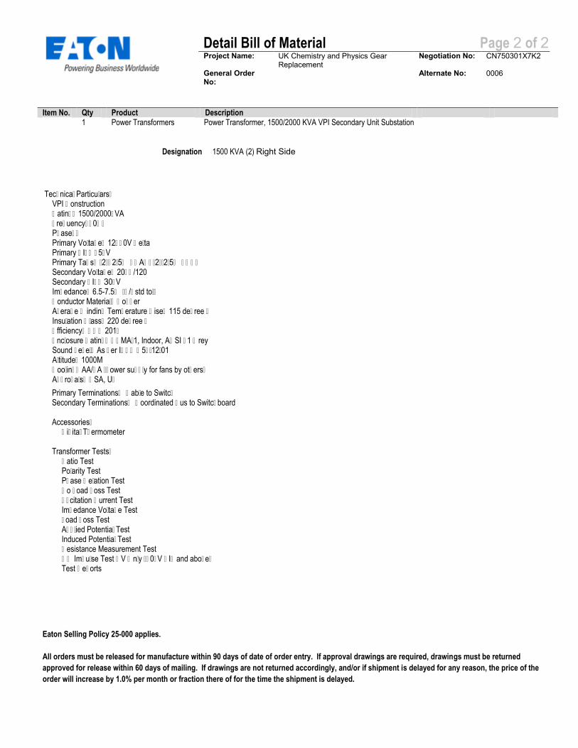
Project Name: UK Chemistry and Physics Gear Replacement
Negotiation No: CN750301X7K2
General Order No:
Alternate No: 0006
Item No. Qty Product Description 1 Power Transformers Power Transformer, 1500/2000 KVA VPI Secondary Unit Substation
Primary Terminations: Cable to SwitchSecondary Terminations: Coordinated Bus to Switchboard
Accessories: Digital Thermometer
Transformer Tests: Ratio Test Polarity Test Phase Relation Test No Load Loss Test Excitation Current Test Impedance Voltage Test Load Loss Test Applied Potential Test Induced Potential Test Resistance Measurement Test QC Impulse Test HV Only (30kV BIL and above) Test Reports
Eaton Selling Policy 25-000 applies.
All orders must be released for manufacture within 90 days of date of order entry. If approval drawings are required, drawings must be returned
approved for release within 60 days of mailing. If drawings are not returned accordingly, and/or if shipment is delayed for any reason, the price of the
order will increase by 1.0% per month or fraction there of for the time the shipment is delayed.
Detail Bill of Material Page 2 of 2
Technical Particulars: VPI Construction Rating: 1500/2000kVA Frequency: 60Hz Phase: 3 Primary Voltage: 12470V Delta Primary BIL: 95kV Primary Taps: (2)+2.5% FCAN; (2)-2.5% FCBN Secondary Voltage: 208Y/120 Secondary BIL: 30kV Impedance: 6.5-7.5% (+/- std tol) Conductor Material: Copper Average Winding Temperature Rise: 115 degree C Insulation Class: 220 degree C Efficiency: DOE 2016 Enclosure Rating: NEMA-1, Indoor, ANSI 61 Grey Sound Level: As per IEEE C57.12.01 Altitude: 1000M Cooling: AA/FA (power supply for fans by others) Approvals: CSA, UL
Designation 1500 KVA (2) Right Side

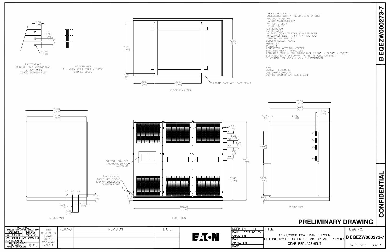
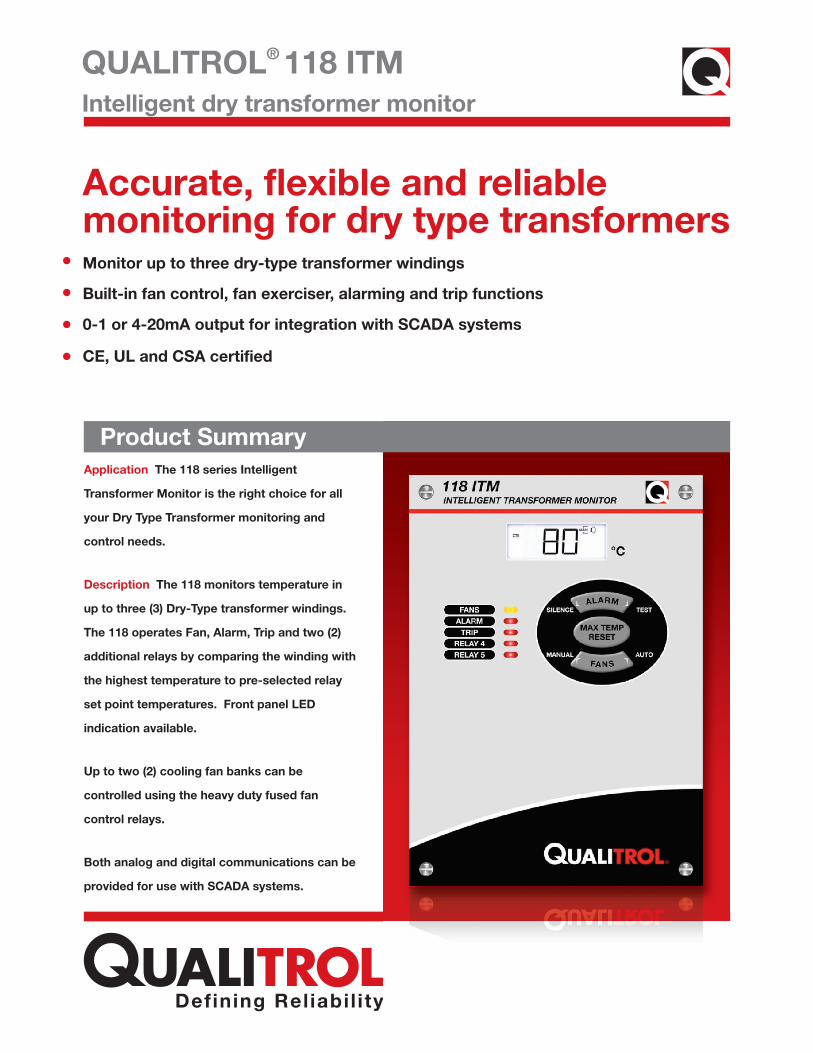
QUALITROL® 118 ITM
Monitor up to three dry-type transformer windings
0-1 or 4-20mA output for integration with SCADA systems
CE, UL and CSA certified
Product Summary
Intelligent dry transformer monitor
Accurate, flexible and reliable monitoring for dry type transformers
Product SummaryApplication The 118 series Intelligent
Transformer Monitor is the right choice for all
your Dry Type Transformer monitoring and
control needs.
Description The 118 monitors temperature in
up to three (3) Dry-Type transformer windings.
The 118 operates Fan, Alarm, Trip and two (2)
additional relays by comparing the winding with
the highest temperature to pre-selected relay
set point temperatures. Front panel LED
indication available.
Up to two (2) cooling fan banks can be
controlled using the heavy duty fused fan
control relays.
Both analog and digital communications can be
provided for use with SCADA systems.
Built-in fan control, fan exerciser, alarming and trip functions

QUALITROL® 118 ITM Intelligent dry transformer monitor
• The 118 ITM monitors up to three (3) Type “K” thermocouples
• Reliable operation through advanced design
• The 118 ITM displays three (3) thermocouple inputs, the storedmaximum temperature and its associated winding
• Fan excerciser is configurable to customer requirements
• The118 ITM has a built-in configurable fan exerciser function thatcan activate fans at periodic intervals providing maximum assetprotection (configuration software required)
• Output Fans: One or two SPST contacts Rated 30 Amps @120/240 VAC 1 HP @ 120 VAC, 2 HP @ 240 VAC for each contact
• Output Alarm: One SPDT contact Rated 10 Amps @ 120 VACor 8 Amps @ 240 VAC (resistive)
• Output Trip: One (1) SPDT contact Rated 10 Amps @ 120 VACor 8 Amps @ 240 VAC (resistive)
• Remote Output: 0-1 mA into a load of up to 10,000 ohms max
• 4-20 mA into a load of up to 500 ohms max
• Optional MODBUS communication via RS-485
• As part of Qualitrol’s drive for quality and reliability on all IntelligentTransformer Monitors, the 118 ITM is rigorously tested to ULstandard 873, Canadian Standard C22.2 No. 24-93 and EUDeclaration of Conformance CE
Thermocouple Monitor
Fan Exerciser
118 ITM Outputs
Certification
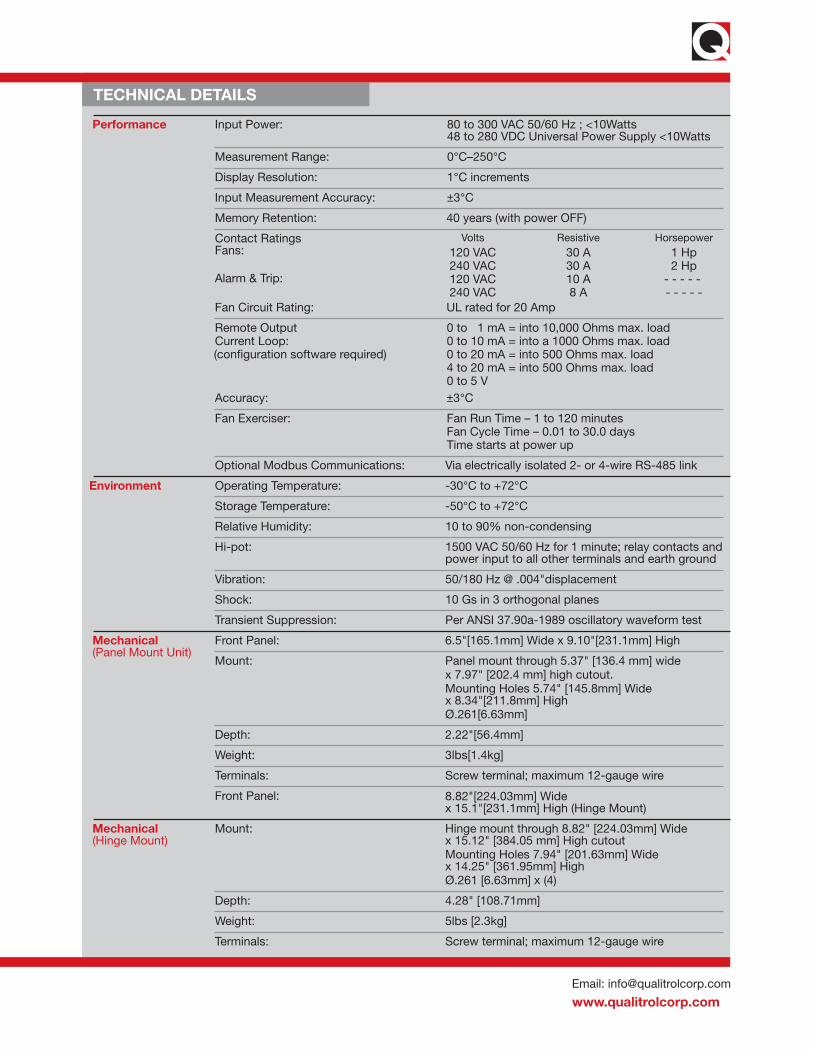
Email: [email protected]
www.qualitrolcorp.com
TECHNICAL DETAILS
Mechanical(Panel Mount Unit)
Mechanical(Hinge Mount)
Panel mount through 5.37" [136.4 mm] widex 7.97" [202.4 mm] high cutout.Mounting Holes 5.74" [145.8mm] Widex 8.34"[211.8mm] HighØ.261[6.63mm]
Mount:
Depth: 2.22"[56.4mm]
Weight: 3lbs[1.4kg]
Terminals: Screw terminal; maximum 12-gauge wire
Mount: Hinge mount through 8.82" [224.03mm] Widex 15.12" [384.05 mm] High cutoutMounting Holes 7.94" [201.63mm] Widex 14.25" [361.95mm] HighØ.261 [6.63mm] x (4)
Depth: 4.28" [108.71mm]
Weight: 5lbs [2.3kg]
Terminals: Screw terminal; maximum 12-gauge wire
Measurement Range: 0°C–250°C
Display Resolution: 1°C increments
Input Measurement Accuracy: ±3°C
Memory Retention: 40 years (with power OFF)
Fan Exerciser: Fan Run Time – 1 to 120 minutesFan Cycle Time – 0.01 to 30.0 daysTime starts at power up
Optional Modbus Communications: Via electrically isolated 2- or 4-wire RS-485 link
Storage Temperature: -50°C to +72°C
Relative Humidity: 10 to 90% non-condensing
Hi-pot: 1500 VAC 50/60 Hz for 1 minute; relay contacts andpower input to all other terminals and earth ground
Vibration: 50/180 Hz @ .004"displacement
Shock: 10 Gs in 3 orthogonal planes
Transient Suppression: Per ANSI 37.90a-1989 oscillatory waveform test
Remote OutputCurrent Loop:
0 to 1 mA = into 10,000 Ohms max. load 0 to 10 mA = into a 1000 Ohms max. load0 to 20 mA = into 500 Ohms max. load4 to 20 mA = into 500 Ohms max. load0 to 5 V
Accuracy: ±3°C
Input Power: 80 to 300 VAC 50/60 Hz ; <10Watts48 to 280 VDC Universal Power Supply <10Watts
Performance
Operating Temperature: -30°C to +72°CEnvironment
Front Panel: 6.5"[165.1mm] Wide x 9.10"[231.1mm] High
Contact RatingsFans:
Alarm & Trip:
Volts Resistive Horsepower120 VAC 30 A 1 Hp240 VAC 30 A 2 Hp120 VAC 10 A - - - - - 240 VAC 8 A - - - - -
Fan Circuit Rating: UL rated for 20 Amp
Front Panel: 8.82"[224.03mm] Widex 15.1"[231.1mm] High (Hinge Mount)
(configuration software required)
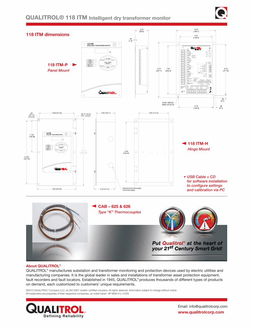
Email: [email protected]
www.qualitrolcorp.com
About QUALITROL®
QUALITROL® manufactures substation and transformer monitoring and protection devices used by electric utilities andmanufacturing companies. It is the global leader in sales and installations of transformer asset protection equipment,fault recorders and fault locators. Established in 1945, QUALITROL® produces thousands of different types of productson demand, each customized to customers’ unique requirements.
QUALITROL® 118 ITM Intelligent dry transformer monitor
118 ITM dimensions
©2010 QUALITROL® Company LLC, an ISO 9001 system certified company. All rights reserved. Information subject to change without notice.All trademarks are properties of their respective companies, as noted herein. AP-M08-01L-01EN.
•USB Cable + CDfor software installationto configure settingsand calibration via PC
CAB – 625 & 626Type “K” Thermocouples
118 ITM-PPanel Mount
118 ITM-HHinge Mount
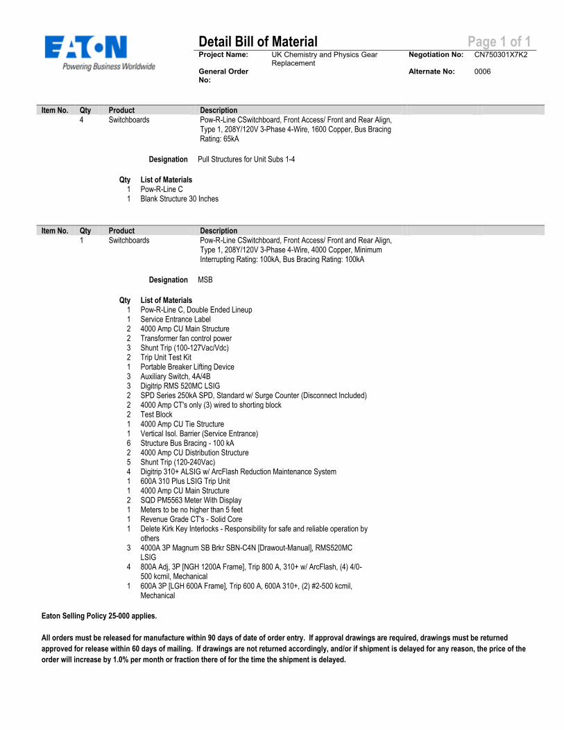
Detail Bill of Material Page 1 of 1
Project Name: UK Chemistry and Physics Gear Replacement
Negotiation No: CN750301X7K2
General Order No:
Alternate No: 0006
Item No. Qty Product Description 4 Switchboards Pow-R-Line CSwitchboard, Front Access/ Front and Rear Align,
Type 1, 208Y/120V 3-Phase 4-Wire, 1600 Copper, Bus Bracing Rating: 65kA
Designation Pull Structures for Unit Subs 1-4
Qty List of Materials 1 Pow-R-Line C 1 Blank Structure 30 Inches
Item No. Qty Product Description 1 Switchboards Pow-R-Line CSwitchboard, Front Access/ Front and Rear Align,
Type 1, 208Y/120V 3-Phase 4-Wire, 4000 Copper, Minimum Interrupting Rating: 100kA, Bus Bracing Rating: 100kA
Designation MSB
Qty List of Materials 1 Pow-R-Line C, Double Ended Lineup 1 Service Entrance Label 2 4000 Amp CU Main Structure 2 Transformer fan control power 3 Shunt Trip (100-127Vac/Vdc) 2 Trip Unit Test Kit 1 Portable Breaker Lifting Device 3 Auxiliary Switch, 4A/4B 3 Digitrip RMS 520MC LSIG 2 SPD Series 250kA SPD, Standard w/ Surge Counter (Disconnect Included) 2 4000 Amp CT's only (3) wired to shorting block 2 Test Block 1 4000 Amp CU Tie Structure 1 Vertical Isol. Barrier (Service Entrance) 6 Structure Bus Bracing - 100 kA 2 4000 Amp CU Distribution Structure 5 Shunt Trip (120-240Vac) 4 Digitrip 310+ ALSIG w/ ArcFlash Reduction Maintenance System 1 600A 310 Plus LSIG Trip Unit 1 4000 Amp CU Main Structure 2 SQD PM5563 Meter With Display 1 Meters to be no higher than 5 feet 1 Revenue Grade CT's - Solid Core 1 Delete Kirk Key Interlocks - Responsibility for safe and reliable operation by
others
3 4000A 3P Magnum SB Brkr SBN-C4N [Drawout-Manual], RMS520MC LSIG
4 800A Adj, 3P [NGH 1200A Frame], Trip 800 A, 310+ w/ ArcFlash, (4) 4/0-500 kcmil, Mechanical
1 600A 3P [LGH 600A Frame], Trip 600 A, 600A 310+, (2) #2-500 kcmil, Mechanical
Eaton Selling Policy 25-000 applies.
All orders must be released for manufacture within 90 days of date of order entry. If approval drawings are required, drawings must be returned
approved for release within 60 days of mailing. If drawings are not returned accordingly, and/or if shipment is delayed for any reason, the price of the
order will increase by 1.0% per month or fraction there of for the time the shipment is delayed.

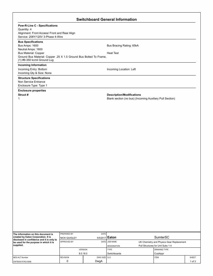
Switchboard General InformationPow-R-Line C - SpecificationsQuantity: 4Alignment: Front Access/ Front and Rear AlignService: 208Y/120V 3-Phase 4-Wire
Bus SpecificationsBus Amps: 1600 Bus Bracing Rating: 65kANeutral Amps: 1600Bus Material: Copper Heat TestGround Bus Material: Copper .25 X 1.5 Ground Bus Bolted To Frame, (1) #6-350 kcmil Ground Lug
Incoming InformationIncoming Entry: Bottom Incoming Location: LeftIncoming Qty & Size: None
Structure SpecificationsNon Service EntranceEnclosure Type: Type 1
Enclosure propertiesStruct # Description/Modifications1 Blank section (no bus) (Incoming Auxiliary Pull Section)
NEG-ALT Number
PREPARED BY DATE
APPROVED BY DATE
VERSION
REVISION DWG SIZE
JOB NAME
DESIGNATION
TYPE
G.O.
DRAWING TYPE
ITEM SHEET
The information on this document is created by Eaton Corporation. It is disclosed in confidence and it is only to be used for the purpose in which it is supplied.
CN750301X7K2-0006
NICK QUIGLEY 5/5/2017
8.0.18.0
0 DwgA
Eaton SumterSCUK Chemistry and Physics Gear ReplacementPull Structures for Unit Subs 1-4
Switchboards CustAppr
1 of 3
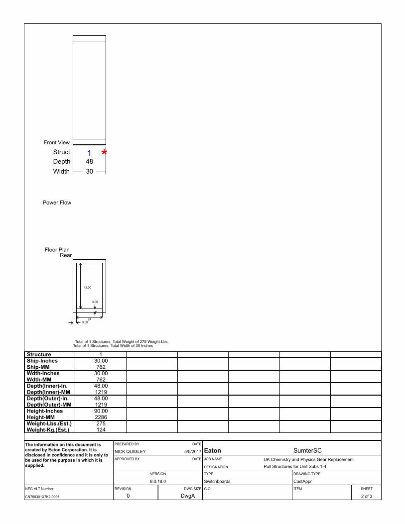
1 *Front View
Power Flow
Floor Plan
Total of 1 Structures, Total Weight of 275 Weight-Lbs.Total of 1 Structures, Total Width of 30 Inches
StructDepthWidth
4830
Rear
42.00
24
3.00
3.00
Structure 1Ship-InchesShip-MM
30.00762
Wdth-InchesWdth-MM
30.00762
Depth(Inner)-In.Depth(Inner)-MM
48.001219
Depth(Outer)-In.Depth(Outer)-MM
48.001219
Height-InchesHeight-MM
90.002286
Weight-Lbs.(Est.)Weight-Kg.(Est.)
275124
NEG-ALT Number
PREPARED BY DATE
APPROVED BY DATE
VERSION
REVISION DWG SIZE
JOB NAME
DESIGNATION
TYPE
G.O.
DRAWING TYPE
ITEM SHEET
The information on this document is created by Eaton Corporation. It is disclosed in confidence and it is only to be used for the purpose in which it is supplied.
CN750301X7K2-0006
NICK QUIGLEY 5/5/2017
8.0.18.0
0 DwgA
Eaton SumterSCUK Chemistry and Physics Gear ReplacementPull Structures for Unit Subs 1-4
Switchboards CustAppr
2 of 3
Switchboard Units InformationStr# Unit Description/Modifications Nameplate
1
NEG-ALT Number
PREPARED BY DATE
APPROVED BY DATE
VERSION
REVISION DWG SIZE
JOB NAME
DESIGNATION
TYPE
G.O.
DRAWING TYPE
ITEM SHEET
The information on this document is created by Eaton Corporation. It is disclosed in confidence and it is only to be used for the purpose in which it is supplied.
CN750301X7K2-0006
NICK QUIGLEY 5/5/2017
8.0.18.0
0 DwgA
Eaton SumterSCUK Chemistry and Physics Gear ReplacementPull Structures for Unit Subs 1-4
Switchboards CustAppr
3 of 3
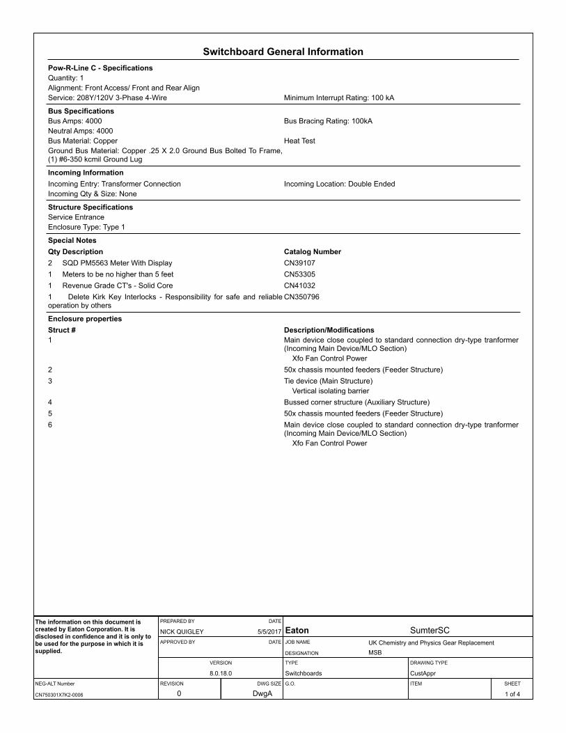
Switchboard General InformationPow-R-Line C - SpecificationsQuantity: 1Alignment: Front Access/ Front and Rear AlignService: 208Y/120V 3-Phase 4-Wire Minimum Interrupt Rating: 100 kA
Bus SpecificationsBus Amps: 4000 Bus Bracing Rating: 100kANeutral Amps: 4000Bus Material: Copper Heat TestGround Bus Material: Copper .25 X 2.0 Ground Bus Bolted To Frame, (1) #6-350 kcmil Ground Lug
Incoming InformationIncoming Entry: Transformer Connection Incoming Location: Double EndedIncoming Qty & Size: None
Structure SpecificationsService EntranceEnclosure Type: Type 1
Special NotesQty Description Catalog Number2 SQD PM5563 Meter With Display CN391071 Meters to be no higher than 5 feet CN533051 Revenue Grade CT's - Solid Core CN410321 Delete Kirk Key Interlocks - Responsibility for safe and reliable operation by others
CN350796
Enclosure propertiesStruct # Description/Modifications1 Main device close coupled to standard connection dry-type tranformer
(Incoming Main Device/MLO Section)Xfo Fan Control Power
2 50x chassis mounted feeders (Feeder Structure)3 Tie device (Main Structure)
Vertical isolating barrier4 Bussed corner structure (Auxiliary Structure)5 50x chassis mounted feeders (Feeder Structure)6 Main device close coupled to standard connection dry-type tranformer
(Incoming Main Device/MLO Section)Xfo Fan Control Power
NEG-ALT Number
PREPARED BY DATE
APPROVED BY DATE
VERSION
REVISION DWG SIZE
JOB NAME
DESIGNATION
TYPE
G.O.
DRAWING TYPE
ITEM SHEET
The information on this document is created by Eaton Corporation. It is disclosed in confidence and it is only to be used for the purpose in which it is supplied.
CN750301X7K2-0006
NICK QUIGLEY 5/5/2017
8.0.18.0
0 DwgA
Eaton SumterSCUK Chemistry and Physics Gear ReplacementMSB
Switchboards CustAppr
1 of 4
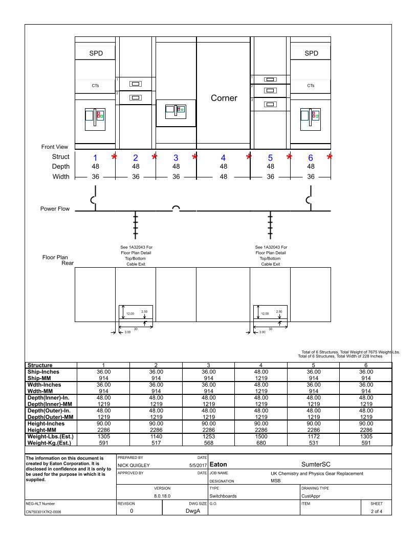
1 *Front View
Power Flow
Floor Plan
StructDepthWidth
4836
SPD
CTs
2 *4836
See 1A32043 ForFloor Plan Detail
Top/BottomCable Exit
1
2
3 *4836
4 *4848
Corner
5 *4836
See 1A32043 ForFloor Plan Detail
Top/BottomCable Exit
1
2
3
6 *
Total of 6 Structures, Total Weight of 7675 Weight-Lbs.Total of 6 Structures, Total Width of 228 Inches
4836
SPD
CTs
Rear
12.00
30
2.50
3.00
12.00
30
2.50
3.00
Structure 1 2 3 4 5 6Ship-InchesShip-MM
36.00 36.00 36.00 48.00 36.00 36.00914 914 914 1219 914 914
Wdth-InchesWdth-MM
36.00 36.00 36.00 48.00 36.00 36.00914 914 914 1219 914 914
Depth(Inner)-In.Depth(Inner)-MM
48.00 48.00 48.00 48.00 48.00 48.001219 1219 1219 1219 1219 1219
Depth(Outer)-In.Depth(Outer)-MM
48.00 48.00 48.00 48.00 48.00 48.001219 1219 1219 1219 1219 1219
Height-InchesHeight-MM
90.00 90.00 90.00 90.00 90.00 90.002286 2286 2286 2286 2286 2286
Weight-Lbs.(Est.)Weight-Kg.(Est.)
1305 1140 1253 1500 1172 1305591 517 568 680 531 591
NEG-ALT Number
PREPARED BY DATE
APPROVED BY DATE
VERSION
REVISION DWG SIZE
JOB NAME
DESIGNATION
TYPE
G.O.
DRAWING TYPE
ITEM SHEET
The information on this document is created by Eaton Corporation. It is disclosed in confidence and it is only to be used for the purpose in which it is supplied.
CN750301X7K2-0006
NICK QUIGLEY 5/5/2017
8.0.18.0
0 DwgA
Eaton SumterSCUK Chemistry and Physics Gear ReplacementMSB
Switchboards CustAppr
2 of 4
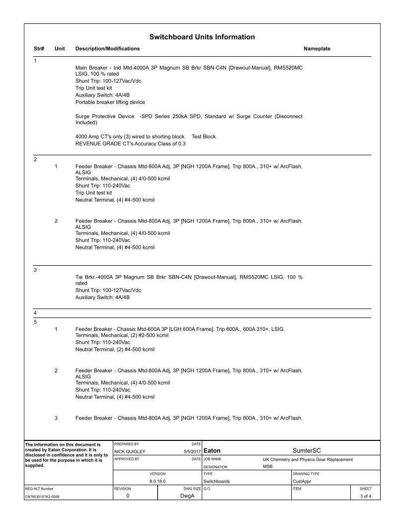
Switchboard Units InformationStr# Unit Description/Modifications Nameplate
1Main Breaker - Ind Mtd-4000A 3P Magnum SB Brkr SBN-C4N [Drawout-Manual], RMS520MC LSIG, 100 % ratedShunt Trip: 100-127Vac/VdcTrip Unit test kitAuxiliary Switch: 4A/4BPortable breaker lifting device
Surge Protective Device -SPD Series 250kA SPD, Standard w/ Surge Counter (Disconnect Included)
4000 Amp CT's only (3) wired to shorting block Test BlockREVENUE GRADE CT's Accuracy Class of 0.3
21 Feeder Breaker - Chassis Mtd-800A Adj, 3P [NGH 1200A Frame], Trip 800A., 310+ w/ ArcFlash,
ALSIGTerminals, Mechanical, (4) 4/0-500 kcmilShunt Trip: 110-240VacTrip Unit test kitNeutral Terminal, (4) #4-500 kcmil
2 Feeder Breaker - Chassis Mtd-800A Adj, 3P [NGH 1200A Frame], Trip 800A., 310+ w/ ArcFlash, ALSIGTerminals, Mechanical, (4) 4/0-500 kcmilShunt Trip: 110-240VacNeutral Terminal, (4) #4-500 kcmil
3Tie Brkr.-4000A 3P Magnum SB Brkr SBN-C4N [Drawout-Manual], RMS520MC LSIG, 100 % ratedShunt Trip: 100-127Vac/VdcAuxiliary Switch: 4A/4B
4
51 Feeder Breaker - Chassis Mtd-600A 3P [LGH 600A Frame], Trip 600A., 600A 310+, LSIG
Terminals, Mechanical, (2) #2-500 kcmilShunt Trip: 110-240VacNeutral Terminal, (2) #4-500 kcmil
2 Feeder Breaker - Chassis Mtd-800A Adj, 3P [NGH 1200A Frame], Trip 800A., 310+ w/ ArcFlash, ALSIGTerminals, Mechanical, (4) 4/0-500 kcmilShunt Trip: 110-240VacNeutral Terminal, (4) #4-500 kcmil
3 Feeder Breaker - Chassis Mtd-800A Adj, 3P [NGH 1200A Frame], Trip 800A., 310+ w/ ArcFlash,
NEG-ALT Number
PREPARED BY DATE
APPROVED BY DATE
VERSION
REVISION DWG SIZE
JOB NAME
DESIGNATION
TYPE
G.O.
DRAWING TYPE
ITEM SHEET
The information on this document is created by Eaton Corporation. It is disclosed in confidence and it is only to be used for the purpose in which it is supplied.
CN750301X7K2-0006
NICK QUIGLEY 5/5/2017
8.0.18.0
0 DwgA
Eaton SumterSCUK Chemistry and Physics Gear ReplacementMSB
Switchboards CustAppr
3 of 4
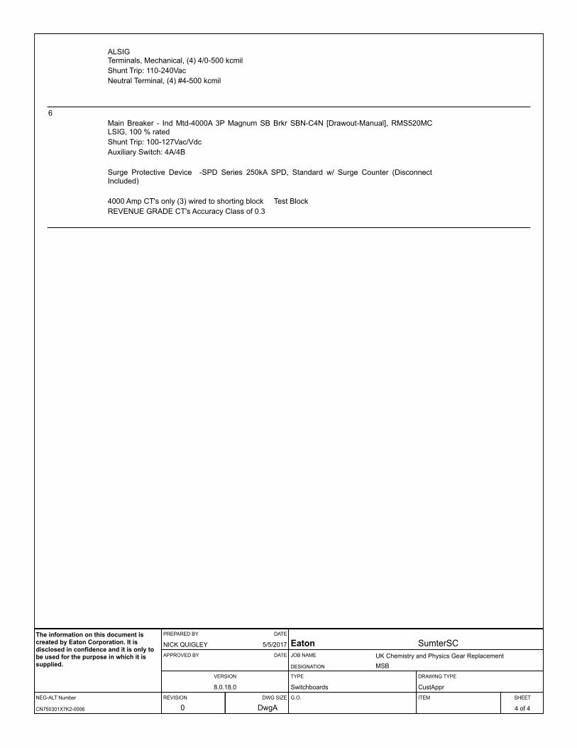
ALSIGTerminals, Mechanical, (4) 4/0-500 kcmilShunt Trip: 110-240VacNeutral Terminal, (4) #4-500 kcmil
6Main Breaker - Ind Mtd-4000A 3P Magnum SB Brkr SBN-C4N [Drawout-Manual], RMS520MC LSIG, 100 % ratedShunt Trip: 100-127Vac/VdcAuxiliary Switch: 4A/4B
Surge Protective Device -SPD Series 250kA SPD, Standard w/ Surge Counter (Disconnect Included)
4000 Amp CT's only (3) wired to shorting block Test BlockREVENUE GRADE CT's Accuracy Class of 0.3
NEG-ALT Number
PREPARED BY DATE
APPROVED BY DATE
VERSION
REVISION DWG SIZE
JOB NAME
DESIGNATION
TYPE
G.O.
DRAWING TYPE
ITEM SHEET
The information on this document is created by Eaton Corporation. It is disclosed in confidence and it is only to be used for the purpose in which it is supplied.
CN750301X7K2-0006
NICK QUIGLEY 5/5/2017
8.0.18.0
0 DwgA
Eaton SumterSCUK Chemistry and Physics Gear ReplacementMSB
Switchboards CustAppr
4 of 4

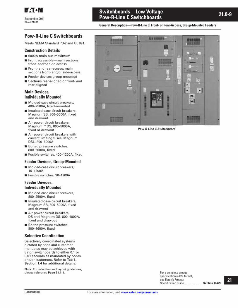
CA08104001E For more information, visit: www.eaton.com/consultants
21.0-9September 2011
Switchboards—Low Voltage
Sheet 21
i
ii
1
2
3
4
5
6
7
8
9
10
11
12
13
14
15
16
17
18
19
20
21
Pow-R-Line C SwitchboardsGeneral Description—Pow-R-Line C, Front- or Rear-Access, Group-Mounted Feeders
009
Pow-R-Line C SwitchboardsMeets NEMA Standard PB-2 and UL 891.
Construction Details■ 6000A main bus maximum■ Front accessible—main sections
front- and/or side-access■ Front- and rear-access; main
sections front- and/or side-access■ Feeder devices group-mounted■ Sections rear-aligned or front- and
rear-aligned
Main Devices, Individually Mounted■ Molded-case circuit breakers,
400–2500A, fixed-mounted■ Insulated-case circuit breakers,
Magnum SB, 800–5000A, fixed and drawout
■ Air power circuit breakers, Magnum™ DS, 800–5000A, fixed or drawout
■ Air power circuit breakers with current limiting fuses, Magnum DSL, 800–5000A
■ Bolted pressure switches, 800–5000A, fixed
■ Fusible switches, 400–1200A, fixed
Feeder Devices, Group-Mounted■ Molded-case circuit breakers,
15–1200A■ Fusible switches, 30–1200A
Feeder Devices,Individually Mounted■ Molded-case circuit breakers,
800–2500A, fixed■ Insulated-case circuit breakers,
Magnum SB, 800–5000A, fixed and drawout
■ Air power circuit breakers, DS and Magnum DS, 800–4000A, fixed and drawout
■ Bolted pressure switches, 800–1600A, fixed
Selective CoordinationSelectively coordinated systems dictated by code and customer mandates may be achieved with Eaton switchboards to either 0.1 or 0.01 seconds as mandated by codes and/or customers. Refer to Tab 1, Section 1.4 for additional details.
Note: For selection and layout guidelines, please reference Page 21.1-1.
Pow-R-Line C Switchboard
For a complete product specification in CSI format, see Eaton’s Product Specification Guide . . . . . . . . . . . . . Section 16429
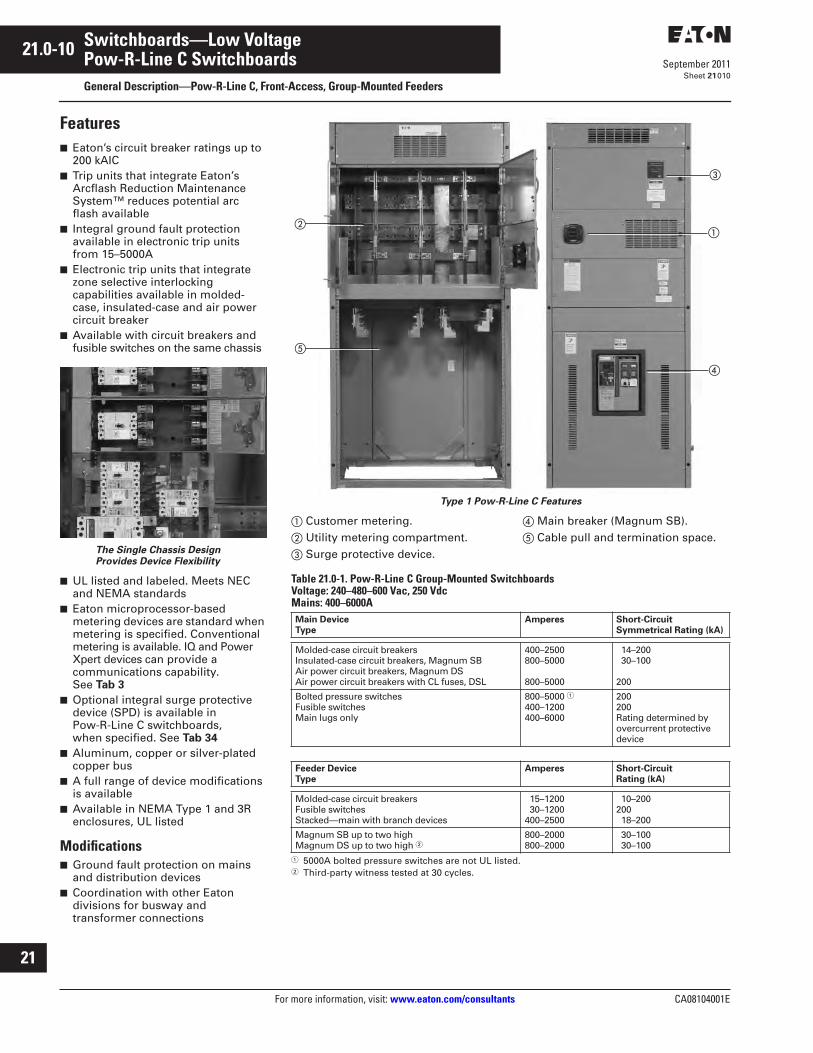
21.0-10
For more information, visit: www.eaton.com/consultants CA08104001E
September 2011
Switchboards—Low Voltage
Sheet 21
i
ii
1
2
3
4
5
6
7
8
9
10
11
12
13
14
15
16
17
18
19
20
21
Pow-R-Line C SwitchboardsGeneral Description—Pow-R-Line C, Front-Access, Group-Mounted Feeders
010
Features■ Eaton’s circuit breaker ratings up to
200 kAIC■ Trip units that integrate Eaton’s
Arcflash Reduction Maintenance System™ reduces potential arc flash available
■ Integral ground fault protection available in electronic trip units from 15–5000A
■ Electronic trip units that integrate zone selective interlocking capabilities available in molded-case, insulated-case and air power circuit breaker
■ Available with circuit breakers and fusible switches on the same chassis
The Single Chassis Design Provides Device Flexibility
■ UL listed and labeled. Meets NEC and NEMA standards
■ Eaton microprocessor-based metering devices are standard when metering is specified. Conventional metering is available. IQ and Power Xpert devices can provide a communications capability. See Tab 3
■ Optional integral surge protective device (SPD) is available in Pow-R-Line C switchboards, when specified. See Tab 34
■ Aluminum, copper or silver-plated copper bus
■ A full range of device modifications is available
■ Available in NEMA Type 1 and 3R enclosures, UL listed
Modifications■ Ground fault protection on mains
and distribution devices■ Coordination with other Eaton
divisions for busway and transformer connections
Type 1 Pow-R-Line C Features
� Customer metering.� Utility metering compartment.� Surge protective device.
� Main breaker (Magnum SB).� Cable pull and termination space.
Table 21.0-1. Pow-R-Line C Group-Mounted SwitchboardsVoltage: 240–480–600 Vac, 250 VdcMains: 400–6000A
� 5000A bolted pressure switches are not UL listed.� Third-party witness tested at 30 cycles.
�
�
��
�
Main Device Type
Amperes Short-CircuitSymmetrical Rating (kA)
Molded-case circuit breakersInsulated-case circuit breakers, Magnum SBAir power circuit breakers, Magnum DSAir power circuit breakers with CL fuses, DSL
400–2500800–5000
800–5000
14–200 30–100
200
Bolted pressure switchesFusible switchesMain lugs only
800–5000 �
400–1200400–6000
200200Rating determined by overcurrent protective device
Feeder Device Type
Amperes Short-Circuit Rating (kA)
Molded-case circuit breakersFusible switchesStacked—main with branch devices
15–1200 30–1200400–2500
10–200200 18–200
Magnum SB up to two highMagnum DS up to two high �
800–2000800–2000
30–100 30–100
21.0-2
For more information, visit:
www.eaton.com/consultants
CA08104001E
September 2011
Switchboards—Low Voltage
Sheet
21
i
ii
1
2
3
4
5
6
7
8
9
10
11
12
13
14
15
16
17
18
19
20
21
General Description
002
Application Considerations and Definitions
Eaton’s Pow-R-Line
®
family of distribution switchboards incorporates new design concepts that fit the ever-increasing need for applications on high short circuit systems, while retaining maximum flexibility, safety and convenience throughout the line.
Front Access
Front-access switchboards align at the rear, enabling them to be placed against a wall (Type Pow-R-Line C™ front accessible). If the main section is deeper than others, due to physical size of the main device, the necessary offset in lineup will occur in front, and the main section will be accessible from the side as well as from the front. Eaton also offers front accessible switchboards that align at the front and rear.
Rear Access
Rear-access switchboards align at the front and the rear. Bus maintenance and cable entry and exit require rear access. There are two types of rear accessible switchboards. Both types use the same incoming utility and/or main structures. The first type uses group-mounted feeder devices with panel construction (Type Pow-R-Line C rear accessible). The second type uses individually compartmentalized feeder devices with load side insulated bus bar extensions (Type Pow-R-Line
i
).
Individually Mounted
Larger overcurrent protective devices (OCPD) may be individually mounted. In most cases, this means that the OCPD is mounted vertically in the switchboard and is connected via bus bar. All insulated case circuit breakers, power air circuit breakers and bolted pressure contact switches are individually mounted. Molded-case circuit breakers 600A and above may be individually mounted when used as a main or as a feeder device feeding other OCPD within a section or adjacent sections.
Compartmentalized Feeder and Branch Devices
Compartmentalized molded-case circuit breakers and fusible switches provide additional isolation. Individually mounted molded-case circuit breakers and fusible switches through 1200A are available in a compartmentalized, rear-access,
rear-connected switchboard. See Pow-R-Line
i
switchboards in this section for details.
Standard Switchboard Height
Standard Pow-R-Line switchboard height is 90.00 inches (2286.0 mm). Contact Eaton for special heights.
Group Mounting
Group-mounted circuit protective devices are an assembly of units mounted on a panelboard type chassis. Units may be molded-case breakers, fusible switches, customer metering and surge protective devices.
A main molded-case breaker or main fusible switch, within the sizes listed for panelboard design, can be included in the panel-mounted assembly in lieu of a separate, individually mounted unit.
Space Only for Future Devices Group-Mounted Construction
Where space only for future circuit protective devices is required, the proper space and a blank filler plate will be supplied. Connections and mounting hardware are not included.
Provision for Future Devices
Where provisions for future circuit protective devices are required, space for the device, corresponding vertical bus, device connectors and the necessary mounting hardware will be supplied.
Bus Bar System
Standard bus in the switchboards is tin-plated aluminum. Copper, silver-plated copper or tin-plated copper are also available.
Main bus and sub-main buses meet UL
®
and NEMA
®
standards for temperature rise on all Pow-R-Line switchboards. Special density rated bus is available.
Overcurrent Devices
To properly select and size overcurrent devices for use in a switchboard, the allowable temperature rise must be taken into account as to its effect on the tripping characteristics of the devices in question per UL 891.
Accordingly, the NEC
®
requires overcurrent devices to be rated not less than 125% of the continuous load they are protecting. To comply with this, an 80% derating factor must be used with all overcurrent devices such as molded-case
breakers and FDPW fusible switches unless they are tested and listed for application at 100% of the rating. All Magnum type breakers and bolted pressure switches are 100% rated.
Short-Circuit Rating
Standard bus and connectors on all switchboards are rated for use on systems capable of producing up to 65,000A rms symmetrical short-circuit current at the incoming terminals.
Increased bus short-circuit ratings equal to that of connected switchboard devices, up to 200,000A rms symmetrical, are available in most Pow-R-Line C switchboards when approved main devices are installed. UL labeled switchboard sections are marked with their applicable short-circuit rating.
When air power circuit breakers are used as feeder devices in a switchboard, these devices may experience up to a 30-cycle (1/2 second) delay if the instantaneous setting is turned off. Eaton has qualified our low voltage switchboards when air power circuit breakers are used as feeders (and mains) to 30 cycles. This rating is not recognized under the UL 891 standard. However, Eaton has witness tested the structure bussing with a qualified National Recognized Testing Laboratory (NRTL) at 30 cycles (1/2 second) up to 100 kAIC symmetrical.
Provision for Busway Entrance and Exit
Busway connections to switchboard sections include cutout and drilling in the top of the switchboard with riser connections from the switchboard device or bus, up to the point where the bus duct enters the switchboard. No connections are furnished external to the switchboard.
In all transactions involving busway attached to switchboards, it is essential that information regarding orientation of the busway with respect to the front of the switchboard be supplied to the coordinating assembly plant.
On Pow-R-Line C switchboards, a solid bus bar is used to connect the bus duct to the individually mounted main device, main or sub-main switchboard bus, or vertical main bus of panel-mounted circuit protective device panels.
Busway fed by group-mounted branch devices are cable connected.
Aluminum riser connections are standard. Copper- or silver-plated copper is available as an option.
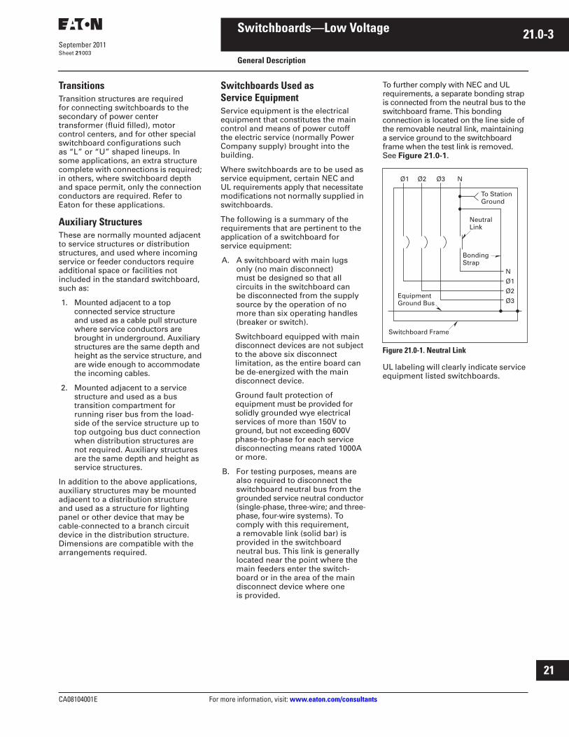
CA08104001E For more information, visit:
www.eaton.com/consultants
21.0-3
September 2011
Switchboards—Low Voltage
Sheet
21
i
ii
1
2
3
4
5
6
7
8
9
10
11
12
13
14
15
16
17
18
19
20
21
General Description
003
Transitions
Transition structures are required for connecting switchboards to the secondary of power center transformer (fluid filled), motor control centers, and for other special switchboard configurations such as “L” or “U” shaped lineups. In some applications, an extra structure complete with connections is required; in others, where switchboard depth and space permit, only the connection conductors are required. Refer to Eaton for these applications.
Auxiliary Structures
These are normally mounted adjacent to service structures or distribution structures, and used where incoming service or feeder conductors require additional space or facilities not included in the standard switchboard, such as:
1. Mounted adjacent to a topconnected service structure and used as a cable pull structure where service conductors are brought in underground. Auxiliary structures are the same depth and height as the service structure, and are wide enough to accommodate the incoming cables.
2. Mounted adjacent to a service structure and used as a bus transition compartment for running riser bus from the load-side of the service structure up to top outgoing bus duct connection when distribution structures are not required. Auxiliary structures are the same depth and height as service structures.
In addition to the above applications, auxiliary structures may be mounted adjacent to a distribution structure and used as a structure for lighting panel or other device that may be cable-connected to a branch circuit device in the distribution structure. Dimensions are compatible with the arrangements required.
Switchboards Used as Service Equipment
Service equipment is the electrical equipment that constitutes the main control and means of power cutoff the electric service (normally Power Company supply) brought into the building.
Where switchboards are to be used as service equipment, certain NEC and UL requirements apply that necessitate modifications not normally supplied in switchboards.
The following is a summary of the requirements that are pertinent to the application of a switchboard for service equipment:
A. A switchboard with main lugsonly (no main disconnect) must be designed so that all circuits in the switchboard can be disconnected from the supply source by the operation of no more than six operating handles (breaker or switch).
Switchboard equipped with main disconnect devices are not subject to the above six disconnect limitation, as the entire board can be de-energized with the main disconnect device.
Ground fault protection of equipment must be provided for solidly grounded wye electrical services of more than 150V to ground, but not exceeding 600V phase-to-phase for each service disconnecting means rated 1000A or more.
B. For testing purposes, means are also required to disconnect the switchboard neutral bus from the
grounded service neutral conductor
(single-phase, three-wire; and three-phase, four-wire systems). To comply with this requirement, a removable link (solid bar) is provided in the switchboard neutral bus. This link is generally located near the point where the main feeders enter the switch-board or in the area of the main disconnect device where one is provided.
To further comply with NEC and UL requirements, a separate bonding strap is connected from the neutral bus to the switchboard frame. This bonding connection is located on the line side of the removable neutral link, maintaining a service ground to the switchboard frame when the test link is removed. See
Figure 21.0-1
.
Figure 21.0-1. Neutral Link
UL labeling will clearly indicate service equipment listed switchboards.
Ø1 Ø2 Ø3 N
N
Ø1
Ø2
Ø3
To StationGround
NeutralLink
BondingStrap
EquipmentGround Bus
Switchboard Frame
21.0-4
For more information, visit:
www.eaton.com/consultants
CA08104001E
September 2011
Switchboards—Low Voltage
Sheet
21
i
ii
1
2
3
4
5
6
7
8
9
10
11
12
13
14
15
16
17
18
19
20
21
General Description
004
Underwriters Laboratories Requirements and Labeling
The basic requirement for obtaining a UL label on a switchboard, is that all the component devices (breakers, switches, and so on) in the switchboard assembly are UL listed. In addition, the switchboard must comply with all applicable provisions of UL 891.
Today’s modern electrical systems require that switchboards offer a wide selection of electrical devices, many of which do not fall within the scope of UL listed devices. Therefore, the conditions under which a switchboard may be labeled are limited.
Listed below are several important guidelines for consideration when aUL label is specified:
1. UL nameplates, where applicable, are supplied for each vertical structure rather than one common nameplate for the complete switchboard lineup. Where all of the component devices in the switchboard are UL listed and all applicable provisions of UL 891 are met, each of the switchboard sections may be labeled.
2. Individual vertical structures of a switchboard may be labeled where they comply with UL requirements, although other vertical structures in the same switchboard lineup may not meet the UL standards, and will not be labeled.
3. All Pow-R-Line C switchboards are UL labeled when all mounted devices are UL listed.
Alternate Power Source Capabilities
Multiple solutions are available to accommodate alternate power sources available. Due to the large number of customer and system requirements, details are not provided in this guide. Eaton offers solutions that include main-main configuration and main-tie-main configurations. Automatic transfer equipment, including UL 1008 listed transfer switches and other automatic transfer schemes, are available.
Automatic Transfer Equipment
For continuity of service, automatic transfer equipment between two incoming sources may be required. This equipment transfers the load upon failure of the normal (or preferred) source to the standby (or alternate) source. Upon restoration of the normal source, the load is automatically transferred back to it. To accomplish this, electrically operated main protective devices (and bus tie devices, if required) must be employed. Additional relays also are required to detect source voltage failure and to transfer control
power, when required. A manual selector
switch is usually provided to select the mode of operation—automatic or manual transfer.
Seismic Qualification
Refer to
Tab 1
for information on seismic qualification for this and other Eaton products.

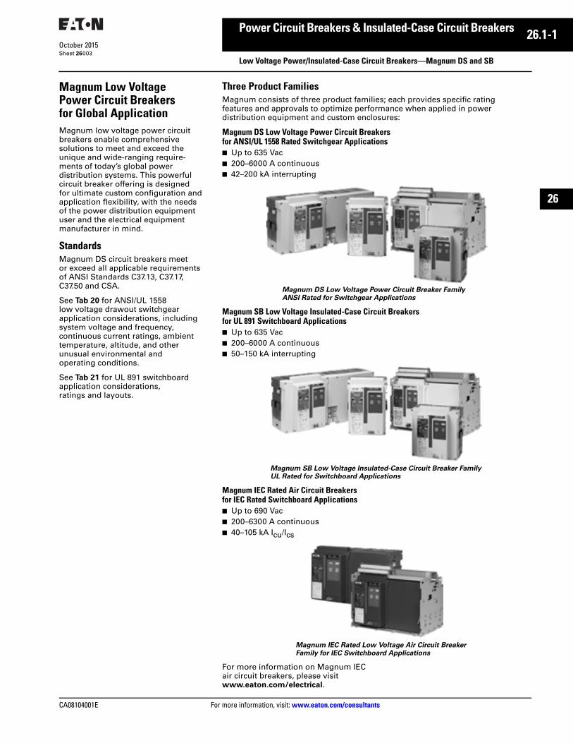
CA08104001E For more information, visit: www.eaton.com/consultants
26.1-1October 2015
Power Circuit Breakers & Insulated-Case Circuit Breakers
Sheet 26
26
Low Voltage Power/Insulated-Case Circuit Breakers—Magnum DS and SB003
Magnum Low Voltage Power Circuit Breakers for Global ApplicationMagnum low voltage power circuit breakers enable comprehensive solutions to meet and exceed the unique and wide-ranging require-ments of today’s global power distribution systems. This powerful circuit breaker offering is designed for ultimate custom configuration and application flexibility, with the needs of the power distribution equipment user and the electrical equipment manufacturer in mind.
StandardsMagnum DS circuit breakers meet or exceed all applicable requirements of ANSI Standards C37.13, C37.17, C37.50 and CSA.
See Tab 20 for ANSI/UL 1558 low voltage drawout switchgear application considerations, including system voltage and frequency, continuous current ratings, ambient temperature, altitude, and other unusual environmental and operating conditions.
See Tab 21 for UL 891 switchboard application considerations, ratings and layouts.
Three Product FamiliesMagnum consists of three product families; each provides specific rating features and approvals to optimize performance when applied in power distribution equipment and custom enclosures:
Magnum DS Low Voltage Power Circuit Breakers for ANSI/UL 1558 Rated Switchgear Applications■ Up to 635 Vac■ 200–6000 A continuous■ 42–200 kA interrupting
Magnum DS Low Voltage Power Circuit Breaker Family ANSI Rated for Switchgear Applications
Magnum SB Low Voltage Insulated-Case Circuit Breakers for UL 891 Switchboard Applications■ Up to 635 Vac■ 200–6000 A continuous■ 50–150 kA interrupting
Magnum SB Low Voltage Insulated-Case Circuit Breaker FamilyUL Rated for Switchboard Applications
Magnum IEC Rated Air Circuit Breakers for IEC Rated Switchboard Applications■ Up to 690 Vac■ 200–6300 A continuous■ 40–105 kA Icu/Ics
Magnum IEC Rated Low Voltage Air Circuit Breaker Family for IEC Switchboard Applications
For more information on Magnum IEC air circuit breakers, please visit www.eaton.com/electrical.
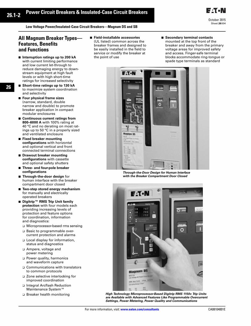
26.1-2
For more information, visit: www.eaton.com/consultants CA08104001E
October 2015
Power Circuit Breakers & Insulated-Case Circuit Breakers
Sheet 26
26
Low Voltage Power/Insulated-Case Circuit Breakers—Magnum DS and SB004
All Magnum Breaker Types—Features, Benefits and Functions■ Interruption ratings up to 200 kA
with current limiting performance and low current let-through to reduce damaging energy to down-stream equipment at high fault levels or with high short-time ratings for increased selectivity
■ Short-time ratings up to 130 kA to maximize system coordination and selectivity
■ Four physical frame sizes (narrow, standard, double narrow and double) to promote breaker application in compact modular enclosures
■ Continuous current ratings from 800–6000 A with 100% rating at 40 °C and no derating on most rat-ings up to 50 °C in a properly sized and ventilated enclosure
■ Fixed breaker mounting configurations with horizontal and optional vertical and front connected terminal connections
■ Drawout breaker mounting configurations with cassette and optional safety shutters
■ Three- and four-pole breaker configurations
■ Through-the-door design for human interface with the breaker compartment door closed
■ Two-step stored energy mechanism for manually and electrically operated breakers
■ Digitrip™ RMS Trip Unit family protection with four models each providing increasing levels of protection and feature options for coordination, information and diagnostics:❑ Microprocessor-based rms sensing❑ Basic to programmable over-
current protection and alarms❑ Local display for information,
status and diagnostics❑ Ampere, voltage and
power metering❑ Power quality, harmonics
and waveform capture❑ Communications with translators
to common protocols❑ Zone selective interlocking for
improved coordination❑ Integral Arcflash Reduction
Maintenance System™❑ Breaker health monitoring
■ Field-installable accessories (UL listed) common across the breaker frames and designed to be easily installed in the field to service or modify the breaker atthe point of use
■ Secondary terminal contacts mounted at the top front of the breaker and away from the primary voltage areas for improved safety and access. Finger-safe terminal blocks accommodate ring-tongue or spade type terminals as standard
Through-the-Door Design for Human Interface with the Breaker Compartment Door Closed
High Technology Microprocessor-Based Digitrip RMS 1150+ Trip Unitsare Available with Advanced Features Like Programmable Overcurrent Settings, Power Metering, Power Quality and Communications
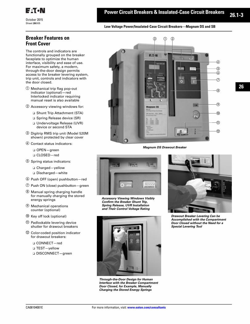
CA08104001E For more information, visit: www.eaton.com/consultants
26.1-3October 2015
Power Circuit Breakers & Insulated-Case Circuit Breakers
Sheet 26
26
Low Voltage Power/Insulated-Case Circuit Breakers—Magnum DS and SB005
Breaker Features on Front CoverThe controls and indicators are functionally grouped on the breaker faceplate to optimize the human interface, visibility and ease of use. For maximum safety, a modern, through-the-door design permits access to the breaker levering system, trip unit, controls and indicators with the door closed.
a Mechanical trip flag pop-out indicator (optional)—redInterlocked indicator requiringmanual reset is also available
b Accessory viewing windows for:
❑ Shunt Trip Attachment (STA)❑ Spring Release device (SR)❑ Undervoltage Release (UVR)
device or second STA
c Digitrip RMS trip unit (Model 520Mshown) protected by clear cover
d Contact status indicators:
❑ OPEN—green❑ CLOSED—red
e Spring status indicators:
❑ Charged—yellow❑ Discharged—white
f Push OFF (open) pushbutton—red
g Push ON (close) pushbutton—green
h Manual spring charging handle for manually charging the stored energy springs
i Mechanical operations counter (optional)
j Key off lock (optional)
k Padlockable levering device shutter for drawout breakers
l Color-coded position indicator for drawout breakers:
❑ CONNECT—red❑ TEST—yellow❑ DISCONNECT—green
Magnum DS Drawout Breaker
Accessory Viewing Windows Visibly Confirm the Breaker Shunt Trip, Spring Release, UVR Installation and Their Control Voltage Rating
Through-the-Door Design for Human Interface with the Breaker Compartment Door Closed, for Example, Manually Charging the Stored Energy Springs
Drawout Breaker Levering Can be Accomplished with the Compartment Door Closed without the Need for a Special Levering Tool
c a b
d
ef
g
h
i
j
k
l
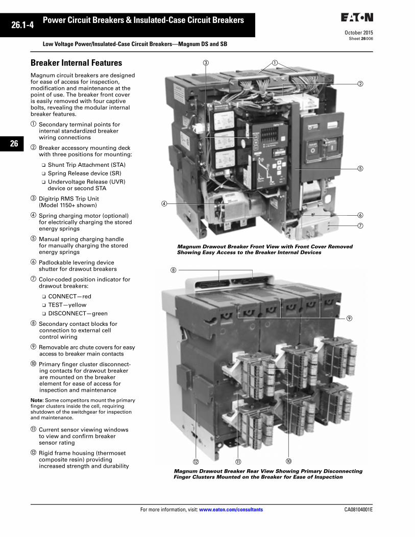
26.1-4
For more information, visit: www.eaton.com/consultants CA08104001E
October 2015
Power Circuit Breakers & Insulated-Case Circuit Breakers
Sheet 26
26
Low Voltage Power/Insulated-Case Circuit Breakers—Magnum DS and SB006
Breaker Internal FeaturesMagnum circuit breakers are designed for ease of access for inspection, modification and maintenance at the point of use. The breaker front cover is easily removed with four captive bolts, revealing the modular internal breaker features.
a Secondary terminal points for internal standardized breaker wiring connections
b Breaker accessory mounting deck with three positions for mounting:
❑ Shunt Trip Attachment (STA)❑ Spring Release device (SR)❑ Undervoltage Release (UVR)
device or second STA
c Digitrip RMS Trip Unit (Model 1150+ shown)
d Spring charging motor (optional) for electrically charging the stored energy springs
e Manual spring charging handle for manually charging the stored energy springs
f Padlockable levering device shutter for drawout breakers
g Color-coded position indicator fordrawout breakers:
❑ CONNECT—red❑ TEST—yellow❑ DISCONNECT—green
h Secondary contact blocks for connection to external cell control wiring
i Removable arc chute covers for easy access to breaker main contacts
j Primary finger cluster disconnect-ing contacts for drawout breaker are mounted on the breaker element for ease of access for inspection and maintenance
Note: Some competitors mount the primary finger clusters inside the cell, requiring shutdown of the switchgear for inspection and maintenance.
k Current sensor viewing windows to view and confirm breaker sensor rating
l Rigid frame housing (thermoset composite resin) providing increased strength and durability
Magnum Drawout Breaker Front View with Front Cover Removed Showing Easy Access to the Breaker Internal Devices
Magnum Drawout Breaker Rear View Showing Primary Disconnecting Finger Clusters Mounted on the Breaker for Ease of Inspection
b
c
d
e
f
g
a
kl j
i
h
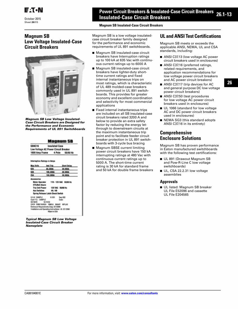
CA08104001E For more information, visit: www.eaton.com/consultants
26.1-13October 2015
Power Circuit Breakers & Insulated-Case Circuit Breakers
Sheet 26
26
Insulated-Case Circuit BreakersMagnum SB Insulated-Case Circuit Breakers
015
Magnum SB Low Voltage Insulated-Case Circuit Breakers
Magnum SB Low Voltage Insulated-Case Circuit Breakers are Designed for the Performance and Economic Requirements of UL 891 Switchboards
Typical Magnum SB Low Voltage Insulated-Case Circuit Breaker Nameplate
Magnum SB is a low voltage insulated-case circuit breaker family designed for the performance and economic requirements of UL 891 switchboards.
■ Magnum SB insulated-case circuit breakers have Interruption ratings up to 100 kA at 635 Vac with continu-ous current ratings up to 6000 A
■ Magnum SB insulated-case circuit breakers have lighter-duty short-time current ratings and fixed internal instantaneous trips on most ratings, which is characteristic of UL 489 molded-case breakers commonly used in UL 891 switch-boards. This provides for greater economy and excellent coordination and selectivity for most commercial applications
■ Fixed internal instantaneous trips are included on all SB insulated-case circuit breakers rated 3200 A and below to provide an extra safety factor by reducing the energy let-through to downstream circuits at the maximum instantaneous trip point and to facilitate feeder circuit breaker protection in UL 891 switch-boards with 3-cycle bus bracing
■ Magnum SBSE current limiting power circuit breakers have 150 kA interrupting ratings at 480 Vac with continuous current ratings up to 5000 A. The short-time current rating is 30 kA for standard frame and 50 kA for double frame breakers
UL and ANSI Test CertificationsMagnum SB meets or exceeds the applicable ANSI, NEMA, UL and CSA standards, including:
■ ANSI C37.13 (low voltage AC power circuit breakers used in enclosures)
■ ANSI C37.16 (preferred ratings, related requirements, and application recommendations for low voltage power circuit breakers and AC power circuit breakers)
■ ANSI C37.17 (trip devices for AC and general purpose DC low voltage power circuit breakers)
■ ANSI C37.50 (test procedures for low voltage AC power circuit breakers used in enclosures)
■ UL 1066 (standard for low voltage AC and DC power circuit breakers used in enclosures)
■ NEMA SG3 (this standard adopts ANSI C37.16 in its entirety)
Comprehensive Enclosure SolutionsMagnum SB has proven performance in Eaton manufactured switchboards with the following test certifications:
■ UL 891 (Drawout Magnum SB and Pow-R-Line C low voltage switchboards)
■ UL, CSA 22.2.31 low voltage assemblies
Approvals■ UL listed: Magnum SB breaker
UL File E52096 and cassette UL File E204565
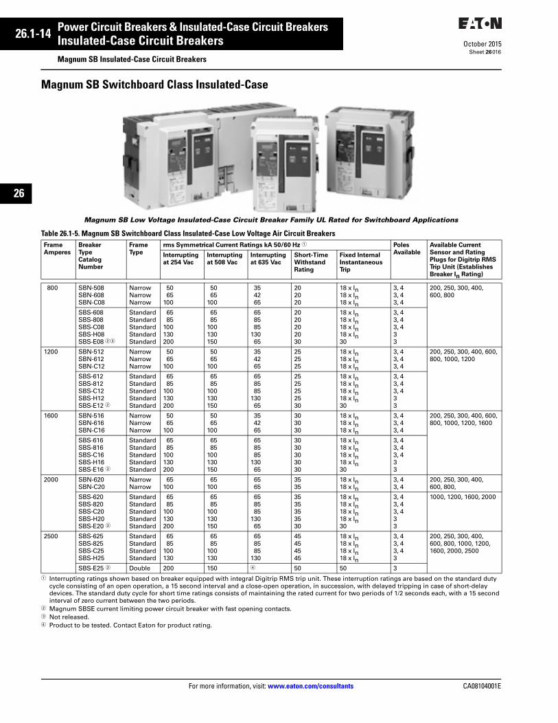
26.1-14
For more information, visit: www.eaton.com/consultants CA08104001E
October 2015
Power Circuit Breakers & Insulated-Case Circuit Breakers
Sheet 26
26
Insulated-Case Circuit BreakersMagnum SB Insulated-Case Circuit Breakers
016
Magnum SB Switchboard Class Insulated-Case
Magnum SB Low Voltage Insulated-Case Circuit Breaker Family UL Rated for Switchboard Applications
Table 26.1-5. Magnum SB Switchboard Class Insulated-Case Low Voltage Air Circuit Breakers
1 Interrupting ratings shown based on breaker equipped with integral Digitrip RMS trip unit. These interruption ratings are based on the standard duty cycle consisting of an open operation, a 15 second interval and a close-open operation, in succession, with delayed tripping in case of short-delay devices. The standard duty cycle for short time ratings consists of maintaining the rated current for two periods of 1/2 seconds each, with a 15 second interval of zero current between the two periods.
2 Magnum SBSE current limiting power circuit breaker with fast opening contacts.3 Not released.4 Product to be tested. Contact Eaton for product rating.
Frame
Amperes
Breaker
Type
Catalog
Number
Frame
Type
rms Symmetrical Current Ratings kA 50/60 Hz 1 Poles
Available
Available Current
Sensor and Rating
Plugs for Digitrip RMS
Trip Unit (Establishes
Breaker In Rating)
Interrupting
at 254 Vac
Interrupting
at 508 Vac
Interrupting
at 635 Vac
Short-Time
Withstand
Rating
Fixed Internal
Instantaneous
Trip
800 SBN-508SBN-608SBN-C08
NarrowNarrowNarrow
5065
100
5065
100
354265
202020
18 x In18 x In18 x In
3, 43, 43, 4
200, 250, 300, 400, 600, 800
SBS-608SBS-808SBS-C08SBS-H08SBS-E08 23
StandardStandardStandardStandardStandard
6585
100130200
6585
100130150
658585
13065
2020202030
18 x In18 x In18 x In18 x In30
3, 43, 43, 433
1200 SBN-512SBN-612SBN-C12
NarrowNarrowNarrow
5065
100
5065
100
354265
252525
18 x In18 x In18 x In
3, 43, 43, 4
200, 250, 300, 400, 600, 800, 1000, 1200
SBS-612SBS-812SBS-C12SBS-H12SBS-E12 2
StandardStandardStandardStandardStandard
6585
100130200
6585
100130150
658585
13065
2525252530
18 x In18 x In18 x In18 x In30
3, 43, 43, 433
1600 SBN-516SBN-616SBN-C16
NarrowNarrowNarrow
5065
100
5065
100
354265
303030
18 x In18 x In18 x In
3, 43, 43, 4
200, 250, 300, 400, 600, 800, 1000, 1200, 1600
SBS-616SBS-816SBS-C16SBS-H16SBS-E16 2
StandardStandardStandardStandardStandard
6585
100130200
6585
100130150
658585
13065
3030303030
18 x In18 x In18 x In18 x In30
3, 43, 43, 433
2000 SBN-620SBN-C20
NarrowNarrow
65100
65100
6565
3535
18 x In18 x In
3, 43, 4
200, 250, 300, 400, 600, 800,
SBS-620SBS-820SBS-C20SBS-H20SBS-E20 2
StandardStandardStandardStandardStandard
6585
100130200
6585
100130150
658585
13065
3535353530
18 x In18 x In18 x In18 x In30
3, 43, 43, 433
1000, 1200, 1600, 2000
2500 SBS-625SBS-825SBS-C25SBS-H25
StandardStandardStandardStandard
6585
100130
6585
100130
658585
130
45454545
18 x In18 x In18 x In18 x In
3, 43, 43, 43
200, 250, 300, 400, 600, 800, 1000, 1200, 1600, 2000, 2500
SBS-E25 2 Double 200 150 4 50 50 3
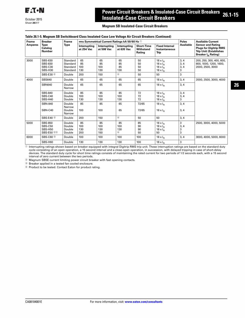
CA08104001E For more information, visit: www.eaton.com/consultants
26.1-15October 2015
Power Circuit Breakers & Insulated-Case Circuit Breakers
Sheet 26
26
Insulated-Case Circuit BreakersMagnum SB Insulated-Case Circuit Breakers
017
Table 26.1-5. Magnum SB Switchboard Class Insulated-Case Low Voltage Air Circuit Breakers (Continued)
1 Interrupting ratings shown based on breaker equipped with integral Digitrip RMS trip unit. These interruption ratings are based on the standard duty cycle consisting of an open operation, a 15 second interval and a close-open operation, in succession, with delayed tripping in case of short-delay devices. The standard duty cycle for short time ratings consists of maintaining the rated current for two periods of 1/2 seconds each, with a 15 second interval of zero current between the two periods.
2 Magnum SBSE current limiting power circuit breaker with fast opening contacts.3 Breaker applied in a tested fan cooled enclosure.4 Product to be tested. Contact Eaton for product rating.
Frame
Amperes
Breaker
Type
Catalog
Number
Frame
Type
rms Symmetrical Current Ratings kA 50/60 Hz 1 Poles
Available
Available Current
Sensor and Rating
Plugs for Digitrip RMS
Trip Unit (Establishes
Breaker In Rating)
Interrupting
at 254 Vac
Interrupting
at 508 Vac
Interrupting
at 635 Vac
Short-Time
Withstand
Rating
Fixed Internal
Instantaneous
Trip
3000 SBS-630SBS-830SBS-C30SBS-H30
StandardStandardStandardStandard
6585
100130
6585
100130
658585
130
50505050
18 x In18 x In18 x In18 x In
3, 43, 43, 43
200, 250, 300, 400, 600, 800, 1000, 1200, 1600, 2000, 2500, 3000
SBS-E30 2 Double 200 150 4 50 50 3
4000 SBS640 Double 65 65 65 65 18 x In 3, 4 2000, 2500, 3000, 4000
SBN640 Double Narrow
65 65 65 65 18 x In 3, 4
SBS-840SBS-C40SBS-H40
DoubleDoubleDouble
85100130
85100130
85100130
727272
18 x In18 x In18 x In
3, 43, 43
SBN-840
SBN-C40
Double NarrowDouble Narrow
85
100
85
100
65
65
72/65
72/65
18 x In
18 x In
3, 4
3, 4
SBS-E40 2 Double 200 150 4 50 50 3, 4
5000 SBS-850SBS-C50SBS-H50SBS-E50 23
DoubleDoubleDoubleDouble
85100130200
85100130150
851001304
85909050
18 x In18 x In18 x In50
33, 433
2500, 3000, 4000, 5000
6000 SBS-C60 3 Double 100 100 100 100 18 x In 3, 4 3000, 4000, 5000, 6000
SBS-H60 Double 130 130 130 100 18 x In 3
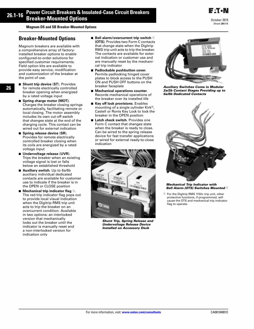
26.1-16
For more information, visit: www.eaton.com/consultants CA08104001E
October 2015
Power Circuit Breakers & Insulated-Case Circuit Breakers
Sheet 26
26
Breaker-Mounted OptionsMagnum DS and SB Breaker-Mounted Options
018
Breaker-Mounted OptionsMagnum breakers are available with a comprehensive array of factory-installed breaker options to enable configured-to-order solutions for specified customer requirements. Field option kits are available to provide easy service, modification and customization of the breaker at the point of use.
■ Shunt trip device (ST). Provides for remote electrically controlled breaker opening when energized by a rated voltage input
■ Spring charge motor (MOT).Charges the breaker closing springs automatically, facilitating remote or local closing. The motor assembly includes its own cut-off switch that changes state at the end of the charging cycle. This contact can be wired out for external indication
■ Spring release device (SR). Provides for remote electrically controlled breaker closing when its coils are energized by a rated voltage input
■ Undervoltage release (UVR). Trips the breaker when an existing voltage signal is lost or falls below an established threshold
■ Auxiliary switch. Up to 6a/6b auxiliary individual dedicated contacts are available for customer use to indicate if the breaker is in the OPEN or CLOSE position
■ Mechanical trip indicator flag 1. The red trip indicator flag pops out to provide local visual indication when the Digitrip RMS trip unit acts to trip the breaker on an overcurrent condition. Available in two options: an interlocked version that mechanically locks out the breaker until the indicator is manually reset and a non-interlocked version for indication only
■ Bell alarm/overcurrent trip switch 1 (OTS). Provides two Form C contacts that change state when the Digitrip RMS trip unit acts to trip the breaker. The contacts are available for exter-nal indication or customer use and are manually reset by the mechani-cal trip indicator
■ Padlockable pushbutton cover. Permits padlocking hinged cover plates to block access to the PUSH ON and PUSH OFF buttons on the breaker faceplate
■ Mechanical operations counter. Records mechanical operations of the breaker over its installed life
■ Key off lock provisions. Enables mounting of a single cylinder Kirk®, Castell or Ronis Key Lock to lock the breaker in the OPEN position
■ Latch check switch. Provides one Form C contact that changes state when the breaker is ready to close. Can be wired to the spring release device for fast transfer applications or wired for external ready-to-close indication
Shunt Trip, Spring Release and Undervoltage Release Device Installed on Accessory Deck
Auxiliary Switches Come in Modular 2a/2b Contact Stages Providing up to 6a/6b Dedicated Contacts
Mechanical Trip Indicator with Bell Alarm (OTS) Switches Mounted 1
1 For the Digitrip RMS 1150+ trip unit, other protective functions, if programmed, will cause the OTS and mechanical trip indicator flag to operate.
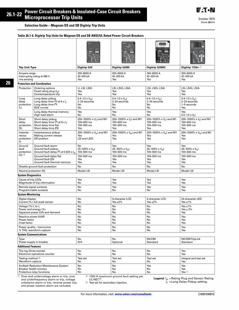
26.1-22
For more information, visit: www.eaton.com/consultants CA08104001E
October 2015
Power Circuit Breakers & Insulated-Case Circuit Breakers
Sheet 26
26
Microprocessor Trip UnitsSelection Guide—Magnum DS and SB Digitrip Trip Units
024
Table 26.1-6. Digitrip Trip Units for Magnum DS and SB ANSI/UL Rated Power Circuit Breakers
1 Over and undervoltage alarm or trip, over and underfrequency alarm or trip, voltage unbalance alarm or trip, reverse power trip, and phase rotation alarm are included.
2 1200 A maximum ground fault setting per UL/NEC®.
3 Test set for secondary injection.
Legend: In = Rating Plug and Sensor Rating.Ir = Long Delay Pickup setting.
Trip Unit Type Digitrip 520 Digitrip 520M Digitrip 520MC Digitrip 1150+ 1
Ampere rangeInterrupting rating at 480 V rms sensing
200–6000 A42–200 kA Yes
200–6000 A42–200 kAYes
200–6000 A42–200 kAYes
200–6000 A42–200 kAYes
Protection and CoordinationProtection Ordering options
Fixed rating plug (In)Overtemperature trip
LI, LSI, LSIGYesYes
LSI, LSIG, LSIAYesYes
LSI, LSIG, LSIAYesYes
LSI, LSIG, LSIAYesYes
Long delayprotection (L)
Long delay pickup Long delay time I2t at 6 x Ir Long delay time I4t IEEE curves
0.4–1.0 x (In)2–24 secondsNoNo
0.4–1.0 x (In)2–24 secondsNoNo
0.4–1.0 x (In)2–24 secondsNoNo
0.4–1.0 x (In)2–24 seconds1–5 secondsYes
Long delay thermal memoryHigh load alarm
YesNo
YesNo
YesNo
Yes0.5–1.0 x (Ir)
Short delayprotection (S)
Short delay pickup Short delay time I2t at 8 x Ir Short delay time flatShort delay time ZSI
200–1000% x (Ir) and M1100–500 ms100–500 msYes
200–1000% x (Ir) and M1 100–500 ms100–500 msYes
200–1000% x (Ir) and M1100–500 ms100–500 msYes
200–1000% x (Ir) and M1100–500 ms100–500 msYes
Instanta-neousprotection (I)
Instantaneous pickupMaking current releaseOff position
200–1000% x (In) and M1YesLSI and LSIG
200–1000% x (In) and M1YesYes
200–1000% x (In) and M1YesYes
200–1000% x (In) and M1YesYes
Groundfaultprotection (G) 2
Ground fault alarmGround fault pickupGround fault delay I2t at 0.625 x In
No25–100% x (In)100–500 ms
Yes25–100% x (In) 100–500 ms
Yes25–100% x (In)100–500 ms
Yes24–100% x (In)100–500 ms
Ground fault delay flatGround fault ZSIGround fault thermal memory
100–500 msYesYes
100–500 msYesYes
100–500 msYesYes
100–500 msYesYes
Disable ground fault protection No No No No
Neutral protection (N) Model LSI Model LSI Model LSI Model LSI
System DiagnosticsCause-of-trip LEDsMagnitude of trip information
Yes No
YesYes
Yes Yes
Yes Yes
Remote signal contactsProgrammable contacts
NoNo
Yes No
Yes No
YesYes
System MonitoringDigital displayCurrent (% ) full scale sensor
NoNo
4-character LCDYes ±2%
4-character LCDYes ±2%
24-character LEDYes ±1%
Voltage (%) L to L Power and energy (%) Apparent power kVA and demand
NoNoNo
NoNoNo
NoNoNo
Yes ±1%Yes ± 2%Yes
Reactive power kVARPower factorCrest factor
NoNoNo
NoNoNo
NoNoNo
YesYesYes
Power quality—harmonics% THD, waveform capture
NoNo
NoNo
NoNo
YesYes
System CommunicationsTypePower supply in breaker
NoN/A
NoOptional
INCOMStandard
INCOM/TripLinkStandard
Additional FeaturesTrip log (three events)Electronic operations counter
NoNo
NoNo
NoNo
YesYes
Testing method 3Waveform capture
Test setNo
Test setNo
Test setNo
Integral and test setYes
Arcflash Reduction Maintenance SystemBreaker health monitorProtective relay functions
NoNoNo
NoNoNo
YesNoNo
Yes YesYes 1
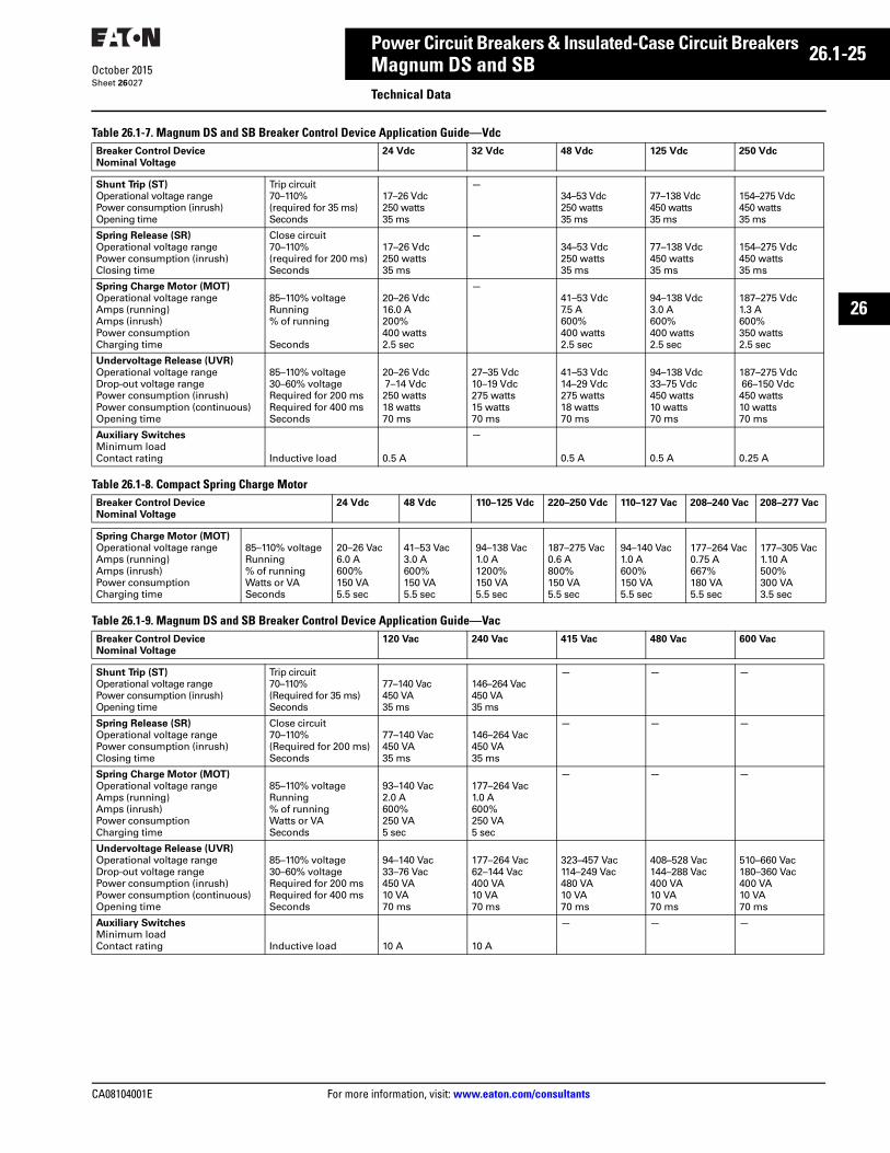
CA08104001E For more information, visit: www.eaton.com/consultants
26.1-25October 2015
Power Circuit Breakers & Insulated-Case Circuit Breakers
Sheet 26
26
Magnum DS and SBTechnical Data
027
Table 26.1-7. Magnum DS and SB Breaker Control Device Application Guide—Vdc
Table 26.1-8. Compact Spring Charge Motor
Table 26.1-9. Magnum DS and SB Breaker Control Device Application Guide—Vac
Breaker Control Device
Nominal Voltage
24 Vdc 32 Vdc 48 Vdc 125 Vdc 250 Vdc
Shunt Trip (ST)
Operational voltage range Power consumption (inrush) Opening time
Trip circuit70–110%(required for 35 ms)Seconds
17–26 Vdc250 watts35 ms
—34–53 Vdc250 watts35 ms
77–138 Vdc450 watts35 ms
154–275 Vdc450 watts35 ms
Spring Release (SR)
Operational voltage rangePower consumption (inrush) Closing time
Close circuit70–110%(required for 200 ms)Seconds
17–26 Vdc250 watts35 ms
—34–53 Vdc250 watts35 ms
77–138 Vdc450 watts35 ms
154–275 Vdc450 watts35 ms
Spring Charge Motor (MOT)
Operational voltage rangeAmps (running)Amps (inrush)Power consumptionCharging time
85–110% voltageRunning% of running
Seconds
20–26 Vdc16.0 A200%400 watts2.5 sec
—41–53 Vdc7.5 A600%400 watts2.5 sec
94–138 Vdc3.0 A600%400 watts2.5 sec
187–275 Vdc1.3 A600%350 watts2.5 sec
Undervoltage Release (UVR)
Operational voltage rangeDrop-out voltage rangePower consumption (inrush)Power consumption (continuous)Opening time
85–110% voltage30–60% voltageRequired for 200 msRequired for 400 msSeconds
20–26 Vdc 7–14 Vdc250 watts18 watts70 ms
27–35 Vdc10–19 Vdc275 watts15 watts70 ms
41–53 Vdc14–29 Vdc275 watts18 watts70 ms
94–138 Vdc33–75 Vdc450 watts10 watts70 ms
187–275 Vdc 66–150 Vdc450 watts10 watts70 ms
Auxiliary Switches
Minimum loadContact rating Inductive load 0.5 A
—
0.5 A 0.5 A 0.25 A
Breaker Control Device
Nominal Voltage
24 Vdc 48 Vdc 110–125 Vdc 220–250 Vdc 110–127 Vac 208–240 Vac 208–277 Vac
Spring Charge Motor (MOT)
Operational voltage rangeAmps (running)Amps (inrush)Power consumptionCharging time
85–110% voltageRunning% of runningWatts or VASeconds
20–26 Vac6.0 A600%150 VA5.5 sec
41–53 Vac3.0 A600%150 VA5.5 sec
94–138 Vac1.0 A1200%150 VA5.5 sec
187–275 Vac0.6 A800%150 VA5.5 sec
94–140 Vac1.0 A600%150 VA5.5 sec
177–264 Vac0.75 A667%180 VA5.5 sec
177–305 Vac1.10 A500%300 VA3.5 sec
Breaker Control Device
Nominal Voltage
120 Vac 240 Vac 415 Vac 480 Vac 600 Vac
Shunt Trip (ST) Operational voltage range Power consumption (inrush) Opening time
Trip circuit70–110%(Required for 35 ms)Seconds
77–140 Vac450 VA35 ms
146–264 Vac450 VA35 ms
— — —
Spring Release (SR)
Operational voltage rangePower consumption (inrush) Closing time
Close circuit70–110%(Required for 200 ms)Seconds
77–140 Vac450 VA35 ms
146–264 Vac450 VA35 ms
— — —
Spring Charge Motor (MOT)
Operational voltage rangeAmps (running)Amps (inrush)Power consumptionCharging time
85–110% voltageRunning% of runningWatts or VASeconds
93–140 Vac2.0 A600%250 VA5 sec
177–264 Vac1.0 A600%250 VA5 sec
— — —
Undervoltage Release (UVR)
Operational voltage rangeDrop-out voltage rangePower consumption (inrush)Power consumption (continuous)Opening time
85–110% voltage30–60% voltageRequired for 200 msRequired for 400 msSeconds
94–140 Vac33–76 Vac450 VA10 VA70 ms
177–264 Vac62–144 Vac400 VA10 VA70 ms
323–457 Vac114–249 Vac480 VA10 VA70 ms
408–528 Vac144–288 Vac400 VA10 VA70 ms
510–660 Vac180–360 Vac400 VA10 VA70 ms
Auxiliary Switches
Minimum loadContact rating Inductive load 10 A 10 A
— — —
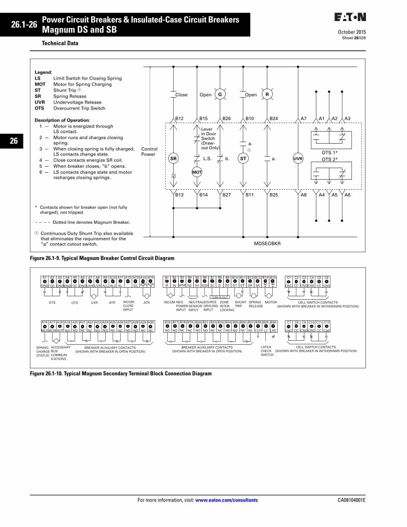
26.1-26
For more information, visit: www.eaton.com/consultants CA08104001E
October 2015
Power Circuit Breakers & Insulated-Case Circuit Breakers
Sheet 26
26
Magnum DS and SBTechnical Data
028
Figure 26.1-9. Typical Magnum Breaker Control Circuit Diagram
Figure 26.1-10. Typical Magnum Secondary Terminal Block Connection Diagram
ControlPower
Close
B12
Lever in Door Switch(Draw-out Only)
L.S. b.
a.
a.OTS 1*OTS 2*
B15 B26
MDSEOBKR
B10 B24 A7
B13 B14 B27 B11 B25 A8
A1 A2 A3
A4 A5 A6
Open OpenG R
SR
MOT
UVRST
Legend:LS Limit Switch for Closing SpringMOT Motor for Spring ChargingST Shunt Trip 1
SR Spring ReleaseUVR Undervoltage ReleaseOTS Overcurrent Trip Switch
Description of Operation:1 — Motor is energized through
LS contact.2 — Motor runs and charges closing
spring.3 — When closing spring is fully charged,
LS contacts change state.4 — Close contacts energize SR coil.5 — When breaker closes, “b” opens.6 — LS contacts change state and motor
recharges closing springs.
* Contacts shown for breaker open (not fullycharged), not tripped.
Dotted line denotes Magnum Breaker. 1 Continuous Duty Shunt Trip also available
that eliminates the requirement for the “a” contact cutout switch.
1
A1 A2 A3 A4 A5 A6 A7 A8 A9 A10 A11 A12 A13 A14 A15
ONO OC UVRONOONO OC ONO UVR ALL ALC AL ICL
UVR ATROTS OTS ATR
ATR ATR
INCOM CLOSEINPUT
A16 A17 A18 A19 A20 A21 A22 A23 A24 A25 A26 A27 A28 A29 A30
MLS ACN NO NCACP NO NC NO NO NC NC NO NO NC NC
SPRING CHARGESTATUS
ACCESSARYBUSCOMMUN-ICATIONS
BREAKER AUXILIARY CONTACTS(SHOWN WITH BREAKER IN OPEN POSITION)
B16 B17 B18 B19 B20 B21 B22 B23 B24 B25 B26 B27 B28 B29 B30
NO NCNO NO NO NONC NCNC NO NC NC LCO LC LNC
BREAKER AUXILIARY CONTACTS(SHOWN WITH BREAKER IN OPEN POSITION)
LATCHCHECKSWITCH
CELL SWITCH CONTACTS(SHOWN WITH BREAKER IN WITHDRAWN POSITION)
C7 C8 C9 C10 C11 C12
CNC CC CNO CNC CC CNO
CELL SWITCH CONTACTS(SHOWN WITH BREAKER IN WITHDRAWN POSITION)
CNC CC CNO CNC CC CNO
C1 C2 C3 C4 C5 C6
INCOM NEGPOWERINPUT
NEUTRALSENSORINPUT
SOURCEGROUNDINPUT
ZONEINTER-LOCKING
SHUNTTRIP
SPRINGRELEASE
MOTOR
COM IN OUT
B1 B2 B3 B4 B5 B6 B7 B8 B9 B10 B11 B12 B13 B14 B15
IP IN NPW N2 N1 SGF ZC ZI ZO ST ST SR SR M M
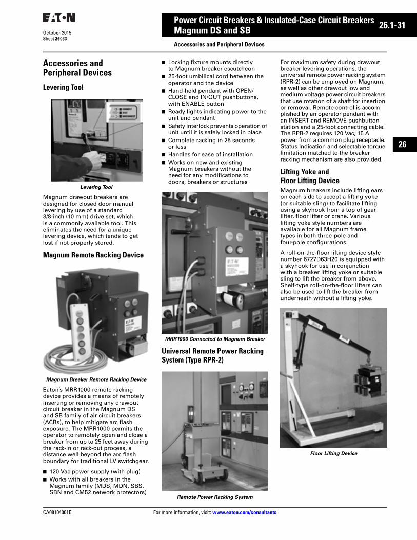
CA08104001E For more information, visit: www.eaton.com/consultants
26.1-31October 2015
Power Circuit Breakers & Insulated-Case Circuit Breakers
Sheet 26
26
Magnum DS and SBAccessories and Peripheral Devices
033
Accessories and Peripheral Devices
Levering Tool
Levering Tool
Magnum drawout breakers are designed for closed door manual levering by use of a standard 3/8-inch (10 mm) drive set, which is a commonly available tool. This eliminates the need for a unique levering device, which tends to get lost if not properly stored.
Magnum Remote Racking Device
Magnum Breaker Remote Racking Device
Eaton’s MRR1000 remote racking device provides a means of remotely inserting or removing any drawout circuit breaker in the Magnum DS and SB family of air circuit breakers (ACBs), to help mitigate arc flash exposure. The MRR1000 permits the operator to remotely open and close a breaker from up to 25 feet away during the rack-in or rack-out process, a distance well beyond the arc flash boundary for traditional LV switchgear.
■ 120 Vac power supply (with plug) ■ Works with all breakers in the
Magnum family (MDS, MDN, SBS, SBN and CM52 network protectors)
■ Locking fixture mounts directly to Magnum breaker escutcheon
■ 25-foot umbilical cord between the operator and the device
■ Hand-held pendant with OPEN/CLOSE and IN/OUT pushbuttons, with ENABLE button
■ Ready lights indicating power to the unit and pendant
■ Safety interlock prevents operation of unit until it is safely locked in place
■ Complete racking in 25 seconds or less
■ Handles for ease of installation■ Works on new and existing
Magnum breakers without the need for any modifications to doors, breakers or structures
MRR1000 Connected to Magnum Breaker
Universal Remote Power Racking System (Type RPR-2)
Remote Power Racking System
For maximum safety during drawout breaker levering operations, the universal remote power racking system (RPR-2) can be employed on Magnum, as well as other drawout low and medium voltage power circuit breakers that use rotation of a shaft for insertion or removal. Remote control is accom-plished by an operator pendant with an INSERT and REMOVE pushbutton station and a 25-foot connecting cable. The RPR-2 requires 120 Vac, 15 A power from a common plug receptacle. Status indication and selectable torque limitation matched to the breaker racking mechanism are also provided.
Lifting Yoke and Floor Lifting DeviceMagnum breakers include lifting ears on each side to accept a lifting yoke (or suitable sling) to facilitate lifting using a skyhook from a top of gear lifter, floor lifter or crane. Various lifting yoke style numbers are available for all Magnum frame types in both three-pole and four-pole configurations.
A roll-on-the-floor lifting device style number 6727D63H20 is equipped with a skyhook for use in conjunction with a breaker lifting yoke or suitable sling to lift the breaker from above. Shelf-type roll-on-the-floor lifters can also be used to lift the breaker from underneath without a lifting yoke.
Floor Lifting Device
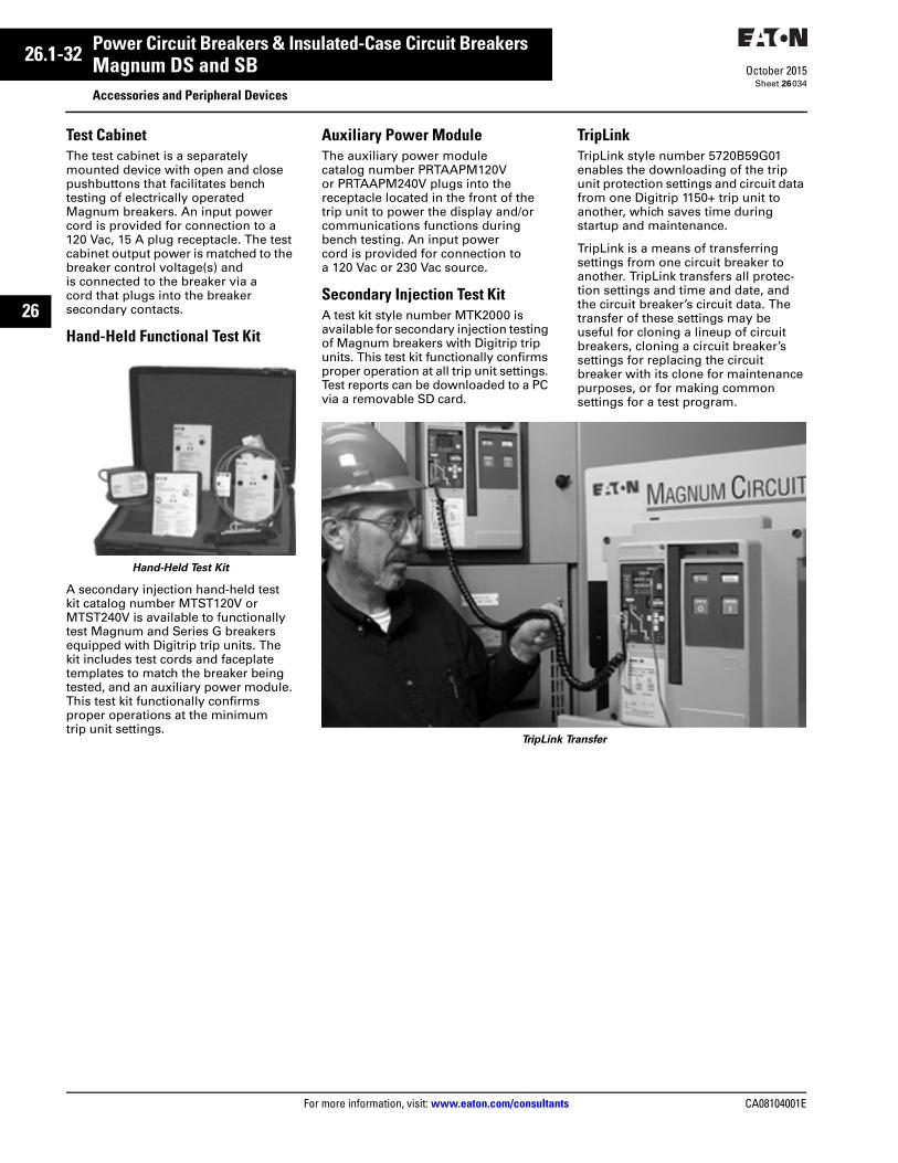
26.1-32
For more information, visit: www.eaton.com/consultants CA08104001E
October 2015
Power Circuit Breakers & Insulated-Case Circuit Breakers
Sheet 26
26
Magnum DS and SBAccessories and Peripheral Devices
034
Test CabinetThe test cabinet is a separately mounted device with open and close pushbuttons that facilitates bench testing of electrically operated Magnum breakers. An input power cord is provided for connection to a 120 Vac, 15 A plug receptacle. The test cabinet output power is matched to the breaker control voltage(s) and is connected to the breaker via a cord that plugs into the breaker secondary contacts.
Hand-Held Functional Test Kit
Hand-Held Test Kit
A secondary injection hand-held test kit catalog number MTST120V or MTST240V is available to functionally test Magnum and Series G breakers equipped with Digitrip trip units. The kit includes test cords and faceplate templates to match the breaker being tested, and an auxiliary power module. This test kit functionally confirms proper operations at the minimum trip unit settings.
Auxiliary Power ModuleThe auxiliary power module catalog number PRTAAPM120V or PRTAAPM240V plugs into the receptacle located in the front of the trip unit to power the display and/or communications functions during bench testing. An input power cord is provided for connection to a 120 Vac or 230 Vac source.
Secondary Injection Test KitA test kit style number MTK2000 is available for secondary injection testing of Magnum breakers with Digitrip trip units. This test kit functionally confirms proper operation at all trip unit settings. Test reports can be downloaded to a PC via a removable SD card.
TripLinkTripLink style number 5720B59G01 enables the downloading of the trip unit protection settings and circuit data from one Digitrip 1150+ trip unit to another, which saves time during startup and maintenance.
TripLink is a means of transferring settings from one circuit breaker to another. TripLink transfers all protec-tion settings and time and date, and the circuit breaker’s circuit data. The transfer of these settings may be useful for cloning a lineup of circuit breakers, cloning a circuit breaker’s settings for replacing the circuit breaker with its clone for maintenance purposes, or for making common settings for a test program.
TripLink Transfer

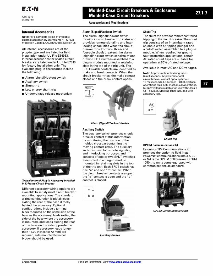
CA08104001E For more information, visit: www.eaton.com/consultants
27.1-7April 2016
Molded-Case Circuit Breakers & Enclosures
Sheet 27
22
23
24
25
26
27
28
29
30
31
32
33
34
35
36
37
38
39
40
41
42
43
Molded-Case Circuit BreakersAccessories and Modifications
011
Internal AccessoriesNote: For a complete listing of available external accessories, see Volume 4—Circuit Protection Catalog, CA08100005E, Section 25.
All internal accessories are of the plug-in type and are listed for field installation under UL File E64983. Internal accessories for sealed circuit breakers are listed under UL File E7819 for factory installation only. The available plug-in accessories include the following:
■ Alarm (signal)/lockout switch■ Auxiliary switch■ Shunt trip■ Low energy shunt trip■ Undervoltage release mechanism
Typical Internal Plug-in Accessory Installed in K-Frame Circuit Breaker
Different accessory wiring options are available to satisfy most circuit breaker mounting applications. The standard wiring configuration is pigtail leads exiting the rear of the base directly behind the accessory. Optional configurations include a terminal block mounted on the same side of the base as the accessory, leads exiting the side of the base where the accessory is mounted, and leads exiting the rear of the base on the side opposite the accessory. If accessory leads longer than 18.00 inches (457.2 mm) are required, side-mounted terminal blocks should be used.
Alarm (Signal)/Lockout SwitchThe alarm (signal)/lockout switch monitors circuit breaker trip status and provides remote signaling and inter-locking capabilities when the circuit breaker trips. For two-, three- and four-pole circuit breakers, the alarm (signal)/lockout switch consists of one or two SPDT switches assembled to a plug-in module mounted in retaining slots in the top of the trip unit. The SPDT switch contacts are identified as make and break contacts. When the circuit breaker trips, the make contact closes and the break contact opens.
Alarm (Signal)/Lockout Switch
Auxiliary SwitchThe auxiliary switch provides circuit breaker contact status information by monitoring the position of the molded crossbar containing the moving contact arms. The auxiliary switch is used for remote signaling and interlocking purposes, and consists of one or two SPDT switches assembled to a plug-in module mounted in retaining slots in the top of the trip unit. Each SPDT switch has one “a” and one “b” contact. When the circuit breaker contacts are open, the ”a“ contact is open and the “b” contact is closed.
Auxiliary Switch
Shunt TripThe shunt trip provides remote controlled tripping of the circuit breaker. The shunt trip consists of an intermittent rated solenoid with a tripping plunger and a cutoff switch assembled to a plug-in module. When required for ground fault protection applications, certain AC rated shunt trips are suitable for operation at 55% of rated voltage.
Available in most AC and DC voltages.
Note: Approximate unlatching time—6 milliseconds. Approximate total circuit breaker contact opening time—18 milliseconds. Endurance—4000 electrical operations plus 1000 mechanical operations. Supply voltages suitable for use with Class 1 GFP devices. Marking label included with accessory kits.
Shunt Trip
OPTIM Communications KitEaton’s OPTIM Communications Kit provides the option to field install PowerNet communications into a K-, L- or N-Frame OPTIM 550 breaker. OPTIM 1050 trip units come equipped with communications as standard.
OPTIM Communications Kit
Make
Break
a
b
ST
a
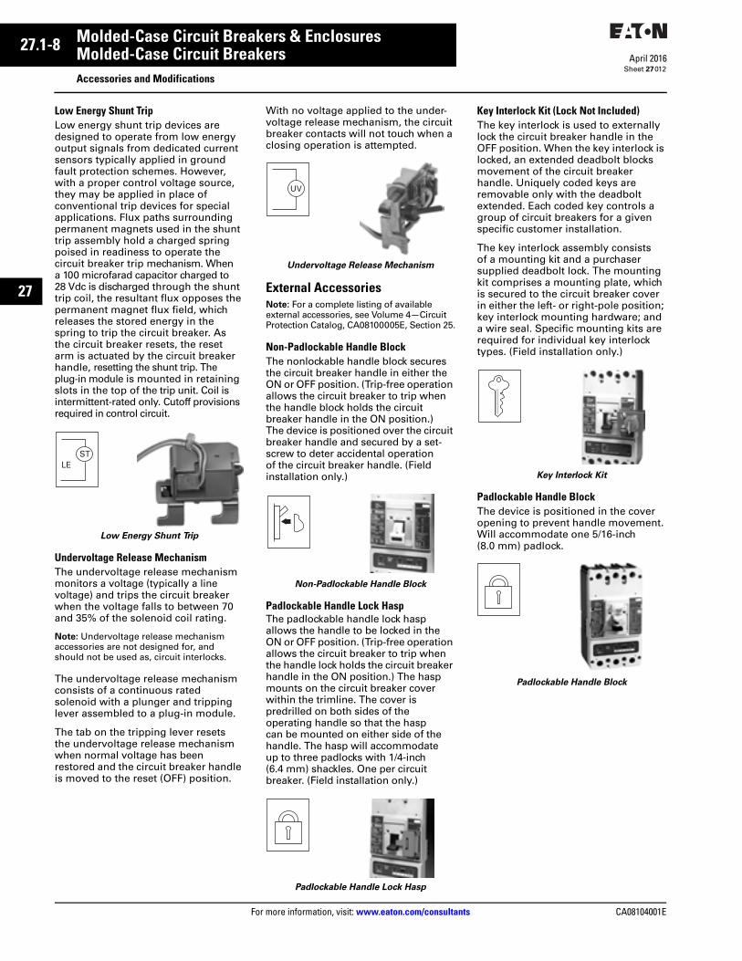
27.1-8
For more information, visit: www.eaton.com/consultants CA08104001E
April 2016
Molded-Case Circuit Breakers & Enclosures
Sheet 27
22
23
24
25
26
27
28
29
30
31
32
33
34
35
36
37
38
39
40
41
42
43
Molded-Case Circuit BreakersAccessories and Modifications
012
Low Energy Shunt TripLow energy shunt trip devices are designed to operate from low energy output signals from dedicated current sensors typically applied in ground fault protection schemes. However, with a proper control voltage source, they may be applied in place of conventional trip devices for special applications. Flux paths surrounding permanent magnets used in the shunt trip assembly hold a charged spring poised in readiness to operate the circuit breaker trip mechanism. When a 100 microfarad capacitor charged to 28 Vdc is discharged through the shunt trip coil, the resultant flux opposes the permanent magnet flux field, which releases the stored energy in the spring to trip the circuit breaker. As the circuit breaker resets, the reset arm is actuated by the circuit breaker handle, resetting the shunt trip. The plug-in module is mounted in retaining slots in the top of the trip unit. Coil is intermittent-rated only. Cutoff provisions required in control circuit.
Low Energy Shunt Trip
Undervoltage Release Mechanism The undervoltage release mechanism monitors a voltage (typically a line voltage) and trips the circuit breaker when the voltage falls to between 70 and 35% of the solenoid coil rating.
Note: Undervoltage release mechanism accessories are not designed for, and should not be used as, circuit interlocks.
The undervoltage release mechanism consists of a continuous rated solenoid with a plunger and tripping lever assembled to a plug-in module.
The tab on the tripping lever resets the undervoltage release mechanism when normal voltage has been restored and the circuit breaker handle is moved to the reset (OFF) position.
With no voltage applied to the under-voltage release mechanism, the circuit breaker contacts will not touch when a closing operation is attempted.
Undervoltage Release Mechanism
External AccessoriesNote: For a complete listing of available external accessories, see Volume 4—Circuit Protection Catalog, CA08100005E, Section 25.
Non-Padlockable Handle BlockThe nonlockable handle block secures the circuit breaker handle in either the ON or OFF position. (Trip-free operation allows the circuit breaker to trip when the handle block holds the circuit breaker handle in the ON position.) The device is positioned over the circuit breaker handle and secured by a set-screw to deter accidental operation of the circuit breaker handle. (Field installation only.)
Non-Padlockable Handle Block
Padlockable Handle Lock HaspThe padlockable handle lock hasp allows the handle to be locked in the ON or OFF position. (Trip-free operation allows the circuit breaker to trip when the handle lock holds the circuit breaker handle in the ON position.) The hasp mounts on the circuit breaker cover within the trimline. The cover is predrilled on both sides of the operating handle so that the hasp can be mounted on either side of the handle. The hasp will accommodate up to three padlocks with 1/4-inch(6.4 mm) shackles. One per circuit breaker. (Field installation only.)
Padlockable Handle Lock Hasp
Key Interlock Kit (Lock Not Included)The key interlock is used to externally lock the circuit breaker handle in the OFF position. When the key interlock is locked, an extended deadbolt blocks movement of the circuit breaker handle. Uniquely coded keys are removable only with the deadbolt extended. Each coded key controls a group of circuit breakers for a given specific customer installation.
The key interlock assembly consists of a mounting kit and a purchaser supplied deadbolt lock. The mounting kit comprises a mounting plate, which is secured to the circuit breaker cover in either the left- or right-pole position; key interlock mounting hardware; and a wire seal. Specific mounting kits are required for individual key interlock types. (Field installation only.)
Key Interlock Kit
Padlockable Handle BlockThe device is positioned in the cover opening to prevent handle movement. Will accommodate one 5/16-inch (8.0 mm) padlock.
Padlockable Handle Block
STLE
UV

Effective August 2009Technical Data TD01005006E
Eaton’s SPD Series for integration intoelectrical distribution equipment
ContentsDescription Page
Introduction . . . . . . . . . . . . . . . . . . . . . . . . . . . . . . . . . . . . . . . . . . . . . . . . . . . . . . . . . . . . . . . . . . . . . . . . . 2Applications . . . . . . . . . . . . . . . . . . . . . . . . . . . . . . . . . . . . . . . . . . . . . . . . . . . . . . . . . . . . . . . . . . . . . . . . . 2Features . . . . . . . . . . . . . . . . . . . . . . . . . . . . . . . . . . . . . . . . . . . . . . . . . . . . . . . . . . . . . . . . . . . . . . . . . . . . 2Standards and certifications . . . . . . . . . . . . . . . . . . . . . . . . . . . . . . . . . . . . . . . . . . . . . . . . . . . . . . . . . . . . 2Feature package options . . . . . . . . . . . . . . . . . . . . . . . . . . . . . . . . . . . . . . . . . . . . . . . . . . . . . . . . . . . . . . . 3Remote display mounting option . . . . . . . . . . . . . . . . . . . . . . . . . . . . . . . . . . . . . . . . . . . . . . . . . . . . . . . . 3Dimensions . . . . . . . . . . . . . . . . . . . . . . . . . . . . . . . . . . . . . . . . . . . . . . . . . . . . . . . . . . . . . . . . . . . . . . . . . 3Performance data . . . . . . . . . . . . . . . . . . . . . . . . . . . . . . . . . . . . . . . . . . . . . . . . . . . . . . . . . . . . . . . . . . . . 5Specifications . . . . . . . . . . . . . . . . . . . . . . . . . . . . . . . . . . . . . . . . . . . . . . . . . . . . . . . . . . . . . . . . . . . . . . . 6Catalog number selection . . . . . . . . . . . . . . . . . . . . . . . . . . . . . . . . . . . . . . . . . . . . . . . . . . . . . . . . . . . . . . 7Technical support information . . . . . . . . . . . . . . . . . . . . . . . . . . . . . . . . . . . . . . . . . . . . . . . . . . . . . . . . . . . 7
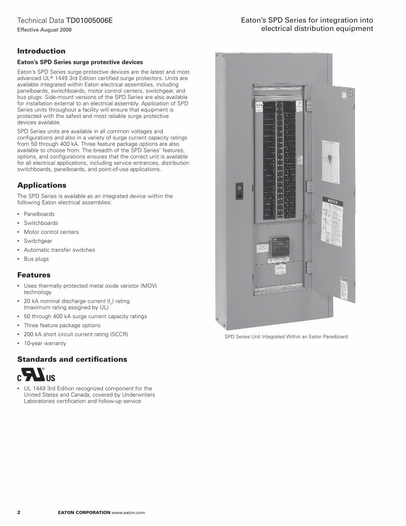
2
Technical Data TD01005006EEffective August 2009
Eaton’s SPD Series for integration into electrical distribution equipment
EATON CORPORATION www.eaton.com
IntroductionEaton’s SPD Series surge protective devices
Eaton’s SPD Series surge protective devices are the latest and most advanced UL� 1449 3rd Edition certified surge protectors. Units are available integrated within Eaton electrical assemblies, including panelboards, switchboards, motor control centers, switchgear, and bus plugs. Side-mount versions of the SPD Series are also available for installation external to an electrical assembly. Application of SPD Series units throughout a facility will ensure that equipment is protected with the safest and most reliable surge protective devices available.
SPD Series units are available in all common voltages and configurations and also in a variety of surge current capacity ratings from 50 through 400 kA. Three feature package options are also available to choose from. The breadth of the SPD Series’ features, options, and configurations ensures that the correct unit is available for all electrical applications, including service entrances, distribution switchboards, panelboards, and point-of-use applications.
ApplicationsThe SPD Series is available as an integrated device within the following Eaton electrical assemblies:
• Panelboards• Switchboards• Motor control centers• Switchgear• Automatic transfer switches• Bus plugs
Features• Uses thermally protected metal oxide varistor (MOV)
technology• 20 kA nominal discharge current (In) rating
(maximum rating assigned by UL)• 50 through 400 kA surge current capacity ratings• Three feature package options• 200 kA short circuit current rating (SCCR)• 10-year warranty
Standards and certifi cations
• UL 1449 3rd Edition recognized component for the United States and Canada, covered by Underwriters Laboratories certification and follow-up service
SPD Series Unit Integrated Within an Eaton Panelboard
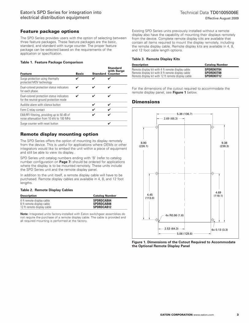
3
Technical Data TD01005006EEffective August 2009
Eaton’s SPD Series for integration into electrical distribution equipment
EATON CORPORATION www.eaton.com
Feature package optionsThe SPD Series provides users with the option of selecting between three feature packages. These feature packages are the basic, standard, and standard with surge counter. The proper feature package can be selected based on the requirements of the application or specification.
Table 1. Feature Package Comparison
Feature Basic Standard
Standard with Surge Counter
Surge protection using thermally protected MOV technology
✔ ✔ ✔
Dual-colored protection status indicators for each phase
✔ ✔ ✔
Dual-colored protection status indicators for the neutral-ground protection mode
✔ ✔ ✔
Audible alarm with silence button ✔ ✔
Form C relay contact ✔ ✔
EMI/RFI filtering, providing up to 50 dB of noise attenuation from 10 kHz to 100 MHz
✔ ✔
Surge counter with reset button ✔
Remote display mounting optionThe SPD Series offers the option of mounting its display remotely from the device. This is useful for applications where OEMs or other integrators would like to embed the unit within a piece of equipment and still be able to view its display.
SPD Series unit catalog numbers ending with ‘B’ (refer to catalog number configuration on Page 7) should be ordered for applications where the display is to be mounted remotely. These units include the SPD Series unit and the remote display panel.
In addition to the unit itself, a remote display cable will have to be purchased. Remote display cables are available in 4, 8, and 12 foot lengths.
Table 2. Remote Display Cables
Description Catalog Number
4 ft remote display cable8 ft remote display cable12 ft remote display cable
SPDRDCAB04SPDRDCAB08SPDRDCAB12
ote: N Integrated units factory-installed with Eaton switchgear assemblies do not require the purchase of a remote display cable. The cable is provided and all required mounting is performed at the factory.
Existing SPD Series units previously installed without a remote display also have the capability of mounting their displays remotely from the device. Complete remote display kits are available that contain all items required to mount the display remotely, including the remote display cable. Remote display kits are available in 4, 8, and 12 foot cable length options.
Table 3. Remote Display Kits
Description Catalog Number
Remote display kit with 4 ft remote display cableRemote display kit with 8 ft remote display cableRemote display kit with 12 ft remote display cable
SPDRDKIT04SPDRDKIT08SPDRDKIT12
For the dimensions of the cutout required to accommodate the remote display panel, see Figure 1 below.
Dimensions
Figure 1. Dimensions of the Cutout Required to Accommodate the Optional Remote Display Panel
2.69 (68.3)
5.38 (136.7)
8.90(226.1)
4.45(113.0)
4x R0.06 (1.6)
2.53 (64.3)
5.06 (128.6)6x 0.13 (3.3)
9.38(238.3)
4.69(119.1)
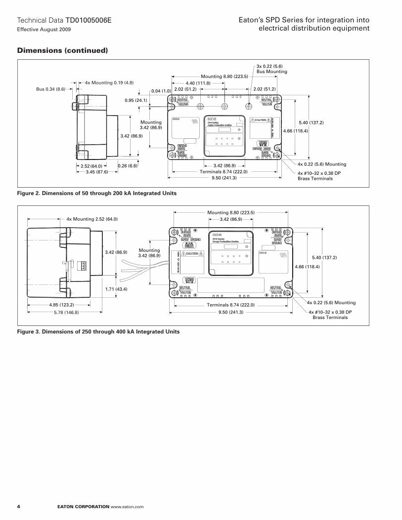
4
Technical Data TD01005006EEffective August 2009
Eaton’s SPD Series for integration into electrical distribution equipment
EATON CORPORATION www.eaton.com
Dimensions (continued)
Figure 2. Dimensions of 50 through 200 kA Integrated Units
Figure 3. Dimensions of 250 through 400 kA Integrated Units
4x Mounting 0.19 (4.8)Bus 0.34 (8.6)
3.42 (86.9)
2.52 (64.0)3.45 (87.6)
0.95 (24.1)
Mounting 8.80 (223.5)4.40 (111.8)
2.02 (51.2)0.04 (1.0) 2.02 (51.2)
5.40 (137.2)
4.66 (118.4)
4x 0.22 (5.6) Mounting
4x #10–32 x 0.38 DP Brass Terminals
3.42 (86.9)Terminals 8.74 (222.0)
9.50 (241.3)
0.26 (6.6)
Mounting3.42 (86.9)
3x 0.22 (5.6) Bus Mounting
5.78 (146.8)
4.85 (123.2)
1.71 (43.4)
3.42 (86.9)
4x Mounting 2.52 (64.0)
9.50 (241.3)
Terminals 8.74 (222.0)
Mounting 8.80 (223.5)3.42 (86.9)
5.40 (137.2)
4.66 (118.4)
4x 0.22 (5.6) Mounting
4x #10–32 x 0.38 DPBrass Terminals
Mounting3.42 (86.9)
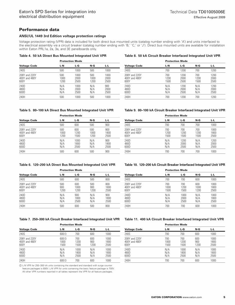
5
Technical Data TD01005006EEffective August 2009
Eaton’s SPD Series for integration into electrical distribution equipment
EATON CORPORATION www.eaton.com
Table 4. 50 kA Direct Bus Mounted Integrated Unit VPR
Voltage Code
Protection Mode
L-N L-G N-G L-L
240S 500 1000 500 1000
208Y and 220Y400Y and 480Y600Y
50010001200
100020002500
50010001200
100020002500
240D480D600D
N/AN/AN/A
100020002500
N/AN/AN/A
90020002500
240H 500 1000 500 1000
Table 5. 80–100 kA Direct Bus Mounted Integrated Unit VPR
Voltage Code
Protection Mode
L-N L-G N-G L-L
240S 500 600 500 900
208Y and 220Y400Y and 480Y600Y
50010001200
60012001500
50010001200
90018002500
240D480D600D
N/AN/AN/A
100018002500
N/AN/AN/A
90018002500
240H 500 600 500 900
Table 6. 120–200 kA Direct Bus Mounted Integrated Unit VPR
Voltage Code
Protection Mode
L-N L-G N-G L-L
240S 500 600 500 800
208Y and 220Y400Y and 480Y600Y
5009001200
60010001200
5009001200
80018002500
240D480D600D
N/AN/AN/A
90018002500
N/AN/AN/A
90018002500
240H 500 600 500 800
Table 7. 250–300 kA Circuit Breaker Interfaced Integrated Unit VPR
Voltage Code
Protection Mode
L-N L-G N-G L-L
240S 600� 700 600 1000
208Y and 220Y400Y and 480Y600Y
600�
10001500
70012001500
6009001200
100018002500
240D480D600D
N/AN/AN/A
100018002500
N/AN/AN/A
100018002500
240H 600� 700 600 1000
� L-N VPR for 250–300 kA units containing the standard and standard with surge counter feature packages is 600V. L-N VPR for units containing the basic feature package is 700V. All other VPR numbers reported in all tables represent the VPR for all feature packages.
Table 8. 50 kA Circuit Breaker Interfaced Integrated Unit VPR
Voltage Code
Protection Mode
L-N L-G N-G L-L
240S 700 1200 700 1200
208Y and 220Y400Y and 480Y600Y
70012001500
120020002500
70012001500
120020002500
240D480D600D
N/AN/AN/A
120020002500
N/AN/AN/A
120020002500
240H 700 1200 700 1200
Table 9. 80–100 kA Circuit Breaker Interfaced Integrated Unit VPR
Voltage Code
Protection Mode
L-N L-G N-G L-L
240S 700 700 700 1000
208Y and 220Y400Y and 480Y600Y
70012001500
70012001500
70012001500
100018002500
240D480D600D
N/AN/AN/A
120020002500
N/AN/AN/A
120020002500
240H 700 700 700 1000
Table 10. 120–200 kA Circuit Breaker Interfaced Integrated Unit VPR
Voltage Code
Protection Mode
L-N L-G N-G L-L
240S 700 700 600 1000
208Y and 220Y400Y and 480Y600Y
70010001500
70012001500
60010001200
100018002500
240D480D600D
N/AN/AN/A
100020002500
N/AN/AN/A
100018002500
240H 700 700 600 1000
Table 11. 400 kA Circuit Breaker Interfaced Integrated Unit VPR
Voltage Code
Protection Mode
L-N L-G N-G L-L
240S 700 700 600 1000
208Y and 220Y400Y and 480Y600Y
70010001500
70012001500
6009001200
100018002500
240D480D600D
N/AN/AN/A
100018002500
N/AN/AN/A
100018002500
240H 700 700 600 1000
Performance dataANSI/UL 1449 3rd Edition voltage protection ratings
Voltage protection rating (VPR) data is included for both direct bus mounted units (catalog number ending with ‘A’) and units interfaced to the electrical assembly via a circuit breaker (catalog number ending with ‘B,’ ‘C,’ or ‘J’). Direct bus mounted units are available for installation within Eaton PRL1a, 2a, 3a, and 3E panelboards only.
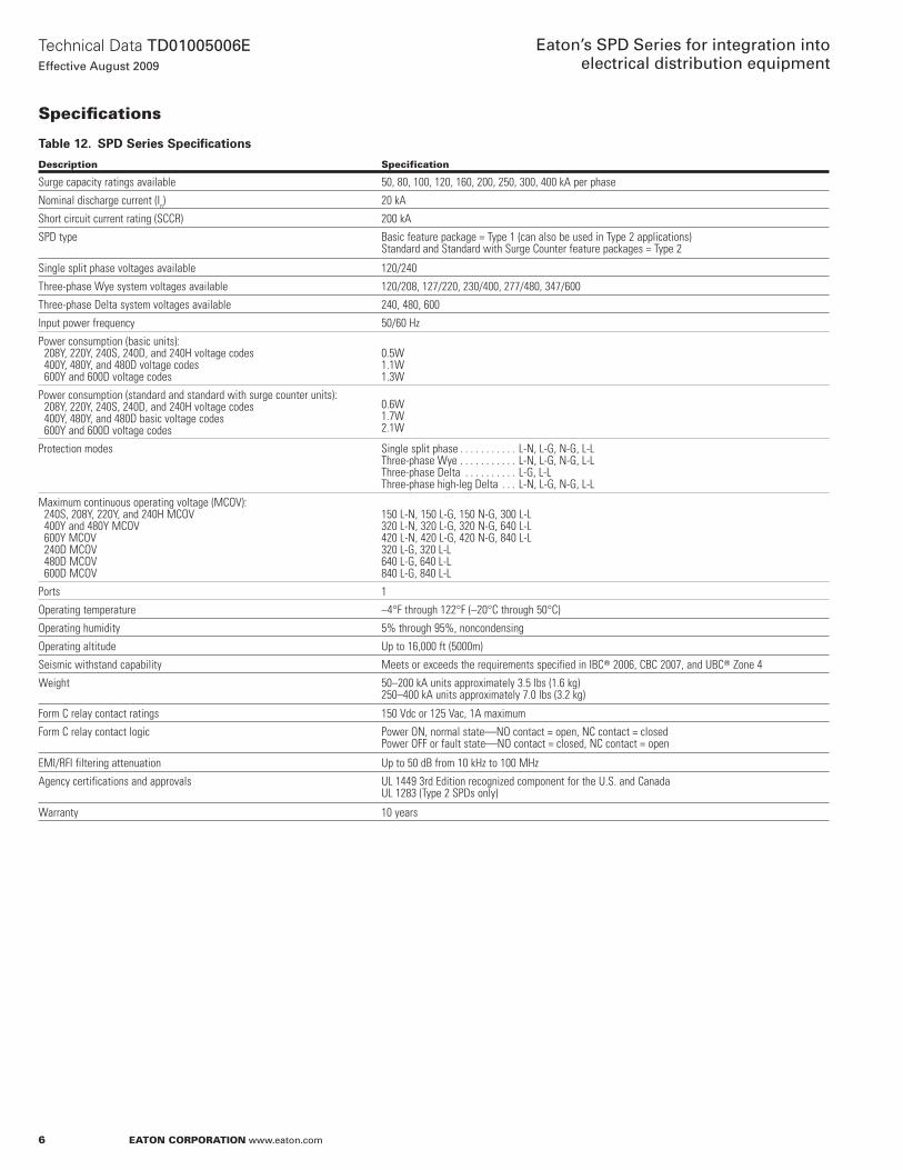
6
Technical Data TD01005006EEffective August 2009
Eaton’s SPD Series for integration into electrical distribution equipment
EATON CORPORATION www.eaton.com
Specifi cations
Table 12. SPD Series Specifications
Description Specification
Surge capacity ratings available 50, 80, 100, 120, 160, 200, 250, 300, 400 kA per phase
Nominal discharge current (In) 20 kA
Short circuit current rating (SCCR) 200 kA
SPD type Basic feature package = Type 1 (can also be used in Type 2 applications)Standard and Standard with Surge Counter feature packages = Type 2
Single split phase voltages available 120/240
Three-phase Wye system voltages available 120/208, 127/220, 230/400, 277/480, 347/600
Three-phase Delta system voltages available 240, 480, 600
Input power frequency 50/60 Hz
Power consumption (basic units): 208Y, 220Y, 240S, 240D, and 240H voltage codes 400Y, 480Y, and 480D voltage codes 600Y and 600D voltage codes
0.5W1.1W1.3W
Power consumption (standard and standard with surge counter units): 208Y, 220Y, 240S, 240D, and 240H voltage codes 400Y, 480Y, and 480D basic voltage codes 600Y and 600D voltage codes
0.6W1.7W2.1W
Protection modes Single split phase . . . . . . . . . . . L-N, L-G, N-G, L-LThree-phase Wye . . . . . . . . . . . L-N, L-G, N-G, L-LThree-phase Delta . . . . . . . . . . L-G, L-LThree-phase high-leg Delta . . . L-N, L-G, N-G, L-L
Maximum continuous operating voltage (MCOV): 240S, 208Y, 220Y, and 240H MCOV 400Y and 480Y MCOV 600Y MCOV 240D MCOV 480D MCOV 600D MCOV
150 L-N, 150 L-G, 150 N-G, 300 L-L320 L-N, 320 L-G, 320 N-G, 640 L-L420 L-N, 420 L-G, 420 N-G, 840 L-L320 L-G, 320 L-L640 L-G, 640 L-L840 L-G, 840 L-L
Ports 1
Operating temperature –4°F through 122°F (–20°C through 50°C)
Operating humidity 5% through 95%, noncondensing
Operating altitude Up to 16,000 ft (5000m)
Seismic withstand capability Meets or exceeds the requirements specified in IBC� 2006, CBC 2007, and UBC� Zone 4
Weight 50–200 kA units approximately 3.5 lbs (1.6 kg)250–400 kA units approximately 7.0 lbs (3.2 kg)
Form C relay contact ratings 150 Vdc or 125 Vac, 1A maximum
Form C relay contact logic Power ON, normal state—NO contact = open, NC contact = closedPower OFF or fault state—NO contact = closed, NC contact = open
EMI/RFI filtering attenuation Up to 50 dB from 10 kHz to 100 MHz
Agency certifications and approvals UL 1449 3rd Edition recognized component for the U.S. and CanadaUL 1283 (Type 2 SPDs only)
Warranty 10 years
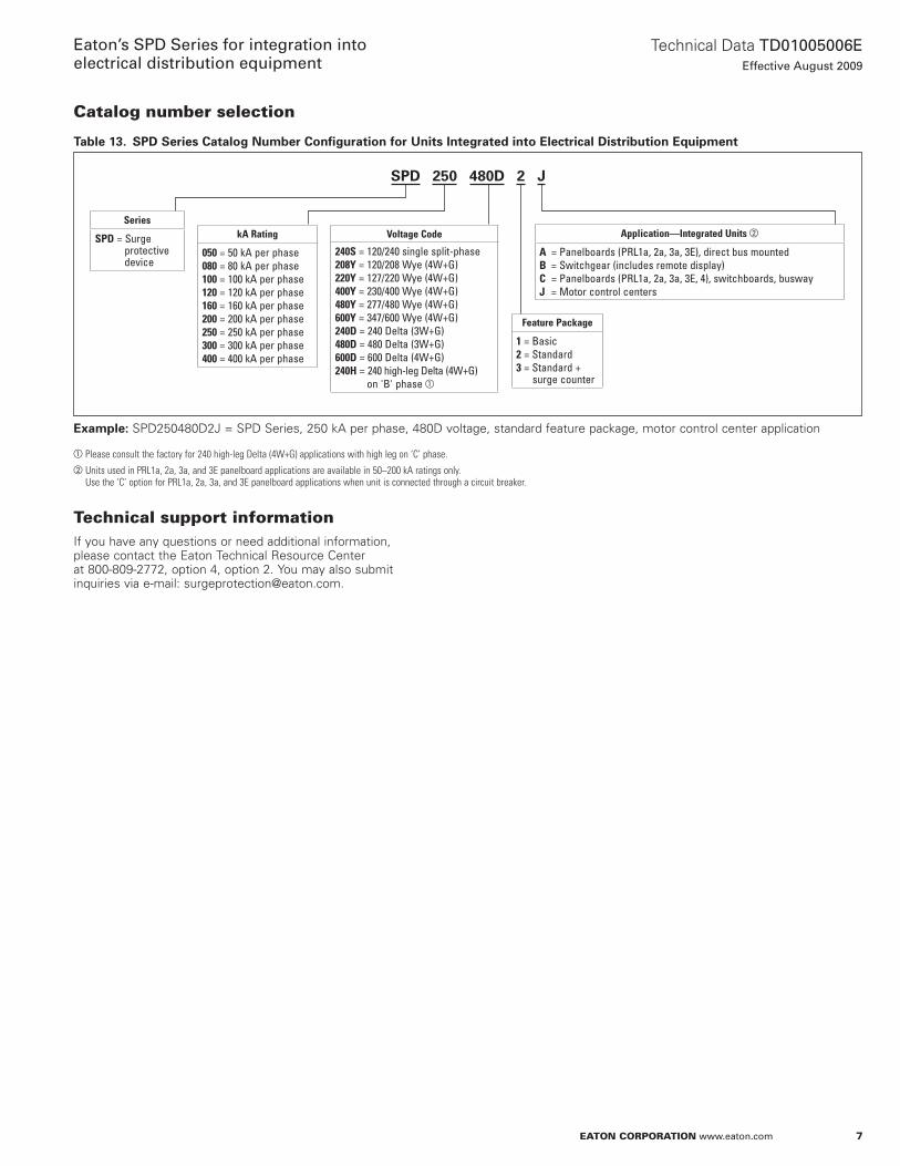
7
Technical Data TD01005006EEffective August 2009
Eaton’s SPD Series for integration into electrical distribution equipment
EATON CORPORATION www.eaton.com
Catalog number selection
Table 13. SPD Series Catalog Number Configuration for Units Integrated into Electrical Distribution Equipment
Example: SPD250480D2J = SPD Series, 250 kA per phase, 480D voltage, standard feature package, motor control center application
� Please consult the factory for 240 high-leg Delta (4W+G) applications with high leg on ‘C’ phase.� Units used in PRL1a, 2a, 3a, and 3E panelboard applications are available in 50–200 kA ratings only.
Use the ‘C’ option for PRL1a, 2a, 3a, and 3E panelboard applications when unit is connected through a circuit breaker.
SPD 250 480D 2 J
Series
SPD = Surge protective device
kA Rating
050 = 50 kA per phase080 = 80 kA per phase100 = 100 kA per phase120 = 120 kA per phase160 = 160 kA per phase200 = 200 kA per phase250 = 250 kA per phase300 = 300 kA per phase400 = 400 kA per phase
Voltage Code
240S = 120/240 single split-phase208Y = 120/208 Wye (4W+G)220Y = 127/220 Wye (4W+G)400Y = 230/400 Wye (4W+G)480Y = 277/480 Wye (4W+G)600Y = 347/600 Wye (4W+G)240D = 240 Delta (3W+G)480D = 480 Delta (3W+G)600D = 600 Delta (4W+G)240H = 240 high-leg Delta (4W+G) on 'B' phase �
Feature Package
1 = Basic 2 = Standard 3 = Standard + surge counter
Application—Integrated Units �
A = Panelboards (PRL1a, 2a, 3a, 3E), direct bus mountedB = Switchgear (includes remote display)C = Panelboards (PRL1a, 2a, 3a, 3E, 4), switchboards, buswayJ = Motor control centers
Technical support information If you have any questions or need additional information, please contact the Eaton Technical Resource Center at 800-809-2772, option 4, option 2. You may also submit inquiries via e-mail: [email protected].
Eaton Corporation
Electrical Sector1111 Superior Ave.Cleveland, OH 44114United States877-ETN-CARE (877-386-2273)Eaton.com
© 2009 Eaton CorporationAll Rights ReservedPrinted in USAPublication No. TD01005006E / Z8902August 2009
PowerChain Management is a registered trademark of Eaton Corporation.
All other trademarks are property of their respective owners.
Technical Data TD01005006EEffective August 2009
Eaton’s SPD Series for integration into electrical distribution equipment

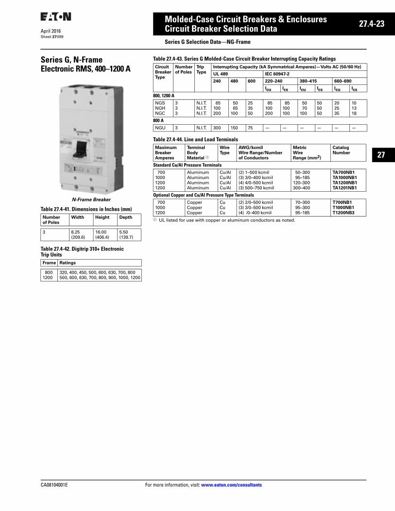
CA08104001E For more information, visit: www.eaton.com/consultants
27.4-23April 2016
Molded-Case Circuit Breakers & Enclosures
Sheet 27
27
Circuit Breaker Selection DataSeries G Selection Data—NG-Frame
099
Series G, N-FrameElectronic RMS, 400–1200 A
N-Frame Breaker
Table 27.4-41. Dimensions in Inches (mm)
Table 27.4-42. Digitrip 310+ Electronic Trip Units
Number
of Poles
Width Height Depth
3 8.25 (209.6)
16.00 (406.4)
5.50 (139.7)
Frame Ratings
8001200
320, 400, 450, 500, 600, 630, 700, 800500, 600, 630, 700, 800, 900, 1000, 1200
Table 27.4-43. Series G Molded-Case Circuit Breaker Interrupting Capacity Ratings
Table 27.4-44. Line and Load Terminals
1 UL listed for use with copper or aluminum conductors as noted.
Circuit
Breaker
Type
Number
of Poles
Trip
Type
Interrupting Capacity (kA Symmetrical Amperes)—Volts AC (50/60 Hz)
UL 489 IEC 60947-2
240 480 600 220–240 380–415 660–690
Icu Ics Icu Ics Icu Ics
800, 1200 ANGSNGHNGC
333
N.I.T.N.I.T.N.I.T.
65100200
5065
100
253550
85100200
85100100
5070
100
505050
202535
101318
800 ANGU 3 N.I.T. 300 150 75 — — — — — —
Maximum
Breaker
Amperes
Terminal
Body
Material 1
Wire
Type
AWG/kcmil
Wire Range/Number
of Conductors
Metric
Wire
Range (mm2)
Catalog
Number
Standard Cu/Al Pressure Terminals700
100012001200
AluminumAluminumAluminumAluminum
Cu/AlCu/AlCu/AlCu/Al
(2) 1–500 kcmil(3) 3/0–400 kcmil(4) 4/0–500 kcmil(3) 500–750 kcmil
50–30095–185
120–300300–400
TA700NB1
TA1000NB1
TA1200NB1
TA1201NB1
Optional Copper and Cu/Al Pressure Type Terminals700
10001200
CopperCopperCopper
CuCuCu
(2) 2/0–500 kcmil(3) 3/0–500 kcmil(4) /0–400 kcmil
70–30095–30095–185
T700NB1
T1000NB1
T1200NB3

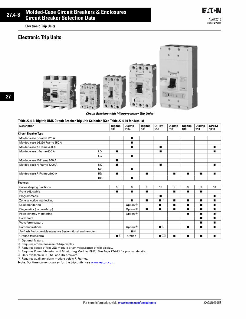
27.4-8
For more information, visit: www.eaton.com/consultants CA08104001E
April 2016
Molded-Case Circuit Breakers & Enclosures
Sheet 27
22
23
24
25
26
27
28
29
30
31
32
33
34
35
36
37
38
39
40
41
42
43
Circuit Breaker Selection DataElectronic Trip Units
084
Electronic Trip Units
Circuit Breakers with Microprocessor Trip Units
Table 27.4-9. Digitrip RMS Circuit Breaker Trip Unit Selection (See Table 27.4-10 for details)
1 Optional feature.2 Requires ammeter/cause-of-trip display.3 Requires cause-of-trip LED module or ammeter/cause-of-trip display.4 Requires Power Metering and Monitoring Module (PM3). See Page 27.4-41 for product details.5 Only available in LG, NG and RG breakers.6 Requires auxiliary alarm module below R-Frames.Note: For time current curves for the trip units, see www.eaton.com.
Description Digitrip
310
Digitrip
310+
Digitrip
510
OPTIM
550
Digitrip
610
Digitrip
810
Digitrip
910
OPTIM
1050
Circuit Breaker TypeMolded-case F-Frame 225 A ■
Molded-case JG250-Frame 250 A ■
Molded-case K-Frame 400 A ■ ■ ■
Molded-case L-Frame 600 A LD ■ ■ ■
LG ■
Molded-case M-Frame 800 A ■
Molded-case N-Frame 1200 A ND ■ ■ ■
NG ■
Molded-case R-Frame 2500 A RD ■ ■ ■ ■ ■ ■
RG ■
FeaturesCurve shaping functions 5 6 9 10 9 9 9 10
Front adjustable ■ ■ ■ ■ ■ ■
Programmable ■ ■
Zone selective interlocking ■ ■ ■ 1 ■ ■ ■ ■
Load monitoring Option 2 ■ ■ ■ ■ ■
Diagnostics (cause-of-trip) Option 3 ■ ■ ■ ■ ■ ■
Power/energy monitoring Option 4 ■ ■ ■
Harmonics ■ ■
Waveform capture ■ ■
Communications Option 4 ■ 1 ■ ■ ■
Arcflash Reduction Maintenance System (local and remote) ■ 5
Ground fault alarm ■ 6 Option ■ 16 ■ ■ ■ ■
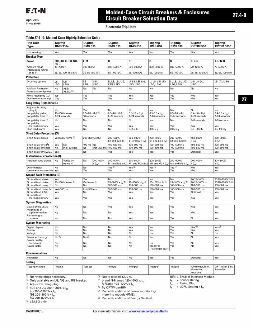
CA08104001E For more information, visit: www.eaton.com/consultants
27.4-9April 2016
Molded-Case Circuit Breakers & Enclosures
Sheet 27
22
23
24
25
26
27
28
29
30
31
32
33
34
35
36
37
38
39
40
41
42
43
Circuit Breaker Selection DataElectronic Trip Units
085
Table 27.4-10. Molded-Case Digitrip Selection Guide
1 No rating plugs necessary.2 Only available on LG, NG and RG breaker.3 Adjust by rating plug.4 FDE and JG 200–1200% x In
LG 200–1200% x InNG 200–900% x InRG 200–800% x In
5 LS/LSG only.
6 Not to exceed 1200 A.7 L- and N-Frames *20–100% x Is.
R-Frame *25–100% x In.h By OPTIMizer/BIM.i Yes, with addition of power monitoring/
metering module (PM3).j Yes, with addition of Energy Sentinel.
BIM = Breaker Interface ModuleIs = Sensor RatingIn = Rating PlugIr = LDPU Setting x In
Trip Unit
Type
Digitrip
RMS 310+
Digitrip
RMS 310
Digitrip
RMS 510
Digitrip
RMS 610
Digitrip
RMS 810
Digitrip
RMS 910
Digitrip
OPTIM 550
Digitrip
OPTIM 1050
rms sensing Yes Yes Yes Yes Yes Yes Yes Yes
Breaker TypeFrame
Ampere range Interrupting rating
at 48 V
FDE, JG, K , LG, NG,
RG 115–2500 A
35, 65, 100, 150 (kA)
L, M
300–800 A
35, 65, 100 (kA)
R
800–5000 A
65, 100 (kA)
R
800–5000 A
65, 100 (kA)
R
800–5000 A
65, 100 (kA)
R
800–5000 A
65, 100 (kA)
K, L, N
70–1200 A
35, 65, 100 (kA)
K, L, N, R
70–5000 A
35, 65, 100 (kA)
ProtectionOrdering options LS
LSGLSILSIG
LSLSG
LSILSIG
LI, LS, LSI, LIG,LSG, LSIG
LI, LS, LSI, LIG,LSG, LSIG
LI, LS, LSI, LIG, LSG, LSIG
LI, LS, LSI, LIG, LSG, LSIG
LSI, LSI (A), LSIG
LSI (A), LISG
Arcflash Reduction Maintenance System
No ALSIALSIG 2
No No No No No No No No
Fixed rated plug (In)Overtemperature trip
NoYes
YesYes
YesYes
YesYes
YesYes
YesYes
YesYes
YesYes
Long Delay Protection (L)Adjustable rating
plug (In)Long delay pickupLong delay time I2t
No40–100% frame2–24 seconds
Yes0.5–1.0 x (In) 310 seconds
No0.5–1.0 x (In)2–24 seconds
No0.5–1.0 x (In)2–24 seconds
No0.5–1.0 x (In)2–24 seconds
No0.5–1.0 x (In)2–24 seconds
No0.4–1.0 x (In)2–24 seconds
No0.4–1.0 x (In)2–24 seconds
Long delay time I4tLong delay
thermal memoryHigh load alarm
No
YesYes
No
YesNo
No
YesNo
No
Yes0.85 x Ir
No
Yes0.85 x Ir
No
Yes0.85 x Ir
1–5 seconds
Yes0.5–1.0 x Ir
1–5 seconds
Yes0.5-1.0 x Ir
Short Delay Protection (S)Short delay pickup Varies by frame 4 200–800% x (In) 200–600%
S1 and S2 x (Ir)200–600% S1 and S2 x (Ir)
200–600% S1 and S2 x (Ir)
200–600% S1 and S2 x (Ir)
150–800% x (Ir)
150–800% x (Ir)
Short delay time I2tShort delay time flat
YesNo
NoInst–300 ms
100 msNo
NoInst–300 ms
100–500 ms100–500 ms
100–500 ms100–500 ms
100–500 ms100–500 ms
100–500 ms100–500 ms
100–500 ms100–500 ms
100–500 ms100–500 ms
Short delay time Z.S.I. Yes No Yes Yes Yes Yes Optional Yes
Instantaneous Protection (I)Instantaneous pickup No Varies by
frame 4No 200–800%
x (In)200–600% M1 and M2 x (In)
200–600% M1 and M2 x (In)
200–600% M1 and M2 x (In)
200–600% M1 and M2 x (In)
200–800% x (In)
200–800% x (In)
DiscriminatorInstantaneous override
NoYes
NoYes
Yes 5Yes
Yes 5Yes
Yes 5Yes
Yes 5Yes
YesYes
YesYes
Ground Fault Protection (G)Ground fault alarmGround fault pickupGround fault delay I2t
Yes20–100% frame 6No
YesVar/frame 6No
No25–100% x In 6100–500 ms
No25–100% x In 6100–500 ms
No25–100% x In 6100–500 ms
No25–100% x In 6100–500 ms
20/25–100% 620/25–100% 6100–500 ms
20/25–100% 7h
20/25–100% 7h
100–500 ms
Ground fault delay flatGround fault Z.S.I.Ground fault
thermal memory
Inst–300 msYes
Yes
Inst–500 msNo
Yes
100–500 msYes
Yes
100–500 msYes
Yes
100–500 msYes
Yes
100–500 msYes
Yes
100–500 msOptional
Yes
100–500 msYes
Yes
System DiagnosticsCause of trip LEDsMagnitude of
trip informationRemote signal
contacts
No
No
No
No
No
No
Yes
No
No
Yes
Yes
Yes
Yes
Yes
Yes
Yes
Yes
Yes
Yes
Yes
No
Yes
Yes
Yes
System MonitoringDigital displayCurrentVoltage
NoNoNo
NoNoNo
NoNoNo
YesYesNo
YesYesNo
YesYesYes
Yes hYesNo
Yes hYesNo
Power and energyPower quality-
harmonicsPower factor
No i
NoNo
No j
NoNo
No
NoNo
No
NoNo
Yes
NoYes (overPowerNet only)
Yes
YesYes
No
NoNo
Yes
YesYes
CommunicationsPowerNet No No No No Yes Yes Optional Yes
TestingTesting method Test kit Test set Integral Integral Integral Integral OPTIMizer, BIM,
PowerNet (optional)
OPTIMizer, BIM,PowerNet
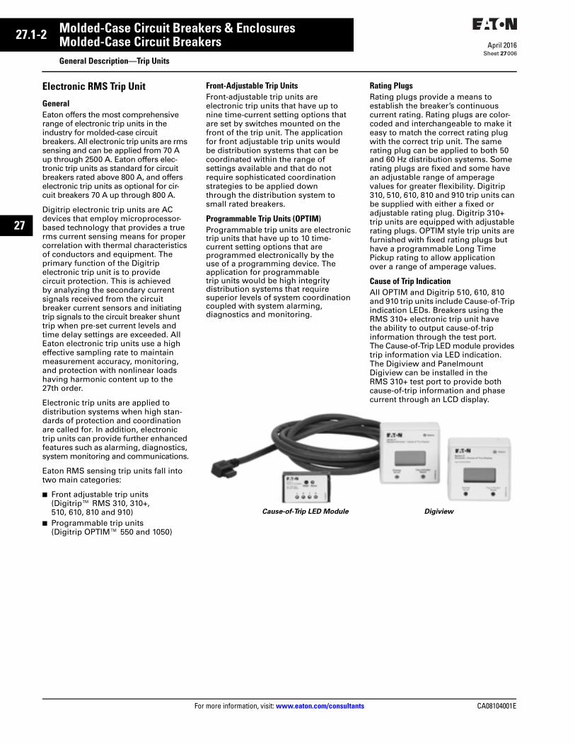
27.1-2
For more information, visit: www.eaton.com/consultants CA08104001E
April 2016
Molded-Case Circuit Breakers & Enclosures
Sheet 27
22
23
24
25
26
27
28
29
30
31
32
33
34
35
36
37
38
39
40
41
42
43
Molded-Case Circuit BreakersGeneral Description—Trip Units
006
Electronic RMS Trip Unit
GeneralEaton offers the most comprehensive range of electronic trip units in the industry for molded-case circuit breakers. All electronic trip units are rms sensing and can be applied from 70 A up through 2500 A. Eaton offers elec-tronic trip units as standard for circuit breakers rated above 800 A, and offers electronic trip units as optional for cir-cuit breakers 70 A up through 800 A.
Digitrip electronic trip units are AC devices that employ microprocessor-based technology that provides a true rms current sensing means for proper correlation with thermal characteristics of conductors and equipment. The primary function of the Digitrip electronic trip unit is to provide circuit protection. This is achieved by analyzing the secondary current signals received from the circuit breaker current sensors and initiating trip signals to the circuit breaker shunt trip when pre-set current levels and time delay settings are exceeded. All Eaton electronic trip units use a high effective sampling rate to maintain measurement accuracy, monitoring, and protection with nonlinear loads having harmonic content up to the 27th order.
Electronic trip units are applied to distribution systems when high stan-dards of protection and coordination are called for. In addition, electronic trip units can provide further enhanced features such as alarming, diagnostics, system monitoring and communications.
Eaton RMS sensing trip units fall into two main categories:
■ Front adjustable trip units (Digitrip™ RMS 310, 310+, 510, 610, 810 and 910)
■ Programmable trip units (Digitrip OPTIM™ 550 and 1050)
Front-Adjustable Trip UnitsFront-adjustable trip units are electronic trip units that have up to nine time-current setting options that are set by switches mounted on the front of the trip unit. The application for front adjustable trip units would be distribution systems that can be coordinated within the range of settings available and that do not require sophisticated coordination strategies to be applied down through the distribution system to small rated breakers.
Programmable Trip Units (OPTIM)Programmable trip units are electronic trip units that have up to 10 time-current setting options that are programmed electronically by the use of a programming device. The application for programmable trip units would be high integrity distribution systems that require superior levels of system coordination coupled with system alarming, diagnostics and monitoring.
Rating PlugsRating plugs provide a means to establish the breaker’s continuous current rating. Rating plugs are color-coded and interchangeable to make it easy to match the correct rating plug with the correct trip unit. The same rating plug can be applied to both 50 and 60 Hz distribution systems. Some rating plugs are fixed and some have an adjustable range of amperage values for greater flexibility. Digitrip 310, 510, 610, 810 and 910 trip units can be supplied with either a fixed or adjustable rating plug. Digitrip 310+ trip units are equipped with adjustable rating plugs. OPTIM style trip units are furnished with fixed rating plugs but have a programmable Long Time Pickup rating to allow application over a range of amperage values.
Cause of Trip IndicationAll OPTIM and Digitrip 510, 610, 810 and 910 trip units include Cause-of-Trip indication LEDs. Breakers using the RMS 310+ electronic trip unit have the ability to output cause-of-trip information through the test port. The Cause-of-Trip LED module provides trip information via LED indication. The Digiview and Panelmount Digiview can be installed in the RMS 310+ test port to provide both cause-of-trip information and phase current through an LCD display.
Cause-of-Trip LED Module Digiview
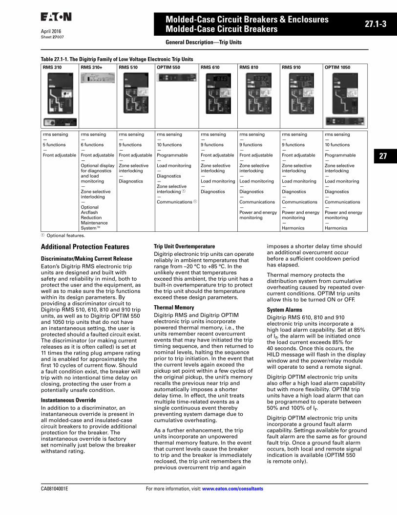
CA08104001E For more information, visit: www.eaton.com/consultants
27.1-3April 2016
Molded-Case Circuit Breakers & Enclosures
Sheet 27
22
23
24
25
26
27
28
29
30
31
32
33
34
35
36
37
38
39
40
41
42
43
Molded-Case Circuit BreakersGeneral Description—Trip Units
007
Table 27.1-1. The Digitrip Family of Low Voltage Electronic Trip Units
1 Optional features.
Additional Protection Features
Discriminator/Making Current ReleaseEaton’s Digitrip RMS electronic trip units are designed and built with safety and reliability in mind, both to protect the user and the equipment, as well as to make sure the trip functions within its design parameters. By providing a discriminator circuit to Digitrip RMS 510, 610, 810 and 910 trip units, as well as to Digitrip OPTIM 550 and 1050 trip units that do not have an instantaneous setting, the user is protected should a faulted circuit exist. The discriminator (or making current releases as it is often called) is set at 11 times the rating plug ampere rating and is enabled for approximately the first 10 cycles of current flow. Should a fault condition exist, the breaker will trip with no intentional time delay on closing, protecting the user from a potentially unsafe condition.
Instantaneous OverrideIn addition to a discriminator, an instantaneous override is present in all molded-case and insulated-case circuit breakers to provide additional protection for the breaker. The instantaneous override is factory set nominally just below the breaker withstand rating.
Trip Unit OvertemperatureDigitrip electronic trip units can operate reliably in ambient temperatures that range from –20 °C to +85 °C. In the unlikely event that temperatures exceed this ambient, the trip unit has a built-in overtemperature trip to protect the trip unit should the temperature exceed these design parameters.
Thermal MemoryDigitrip RMS and Digitrip OPTIM electronic trip units incorporate powered thermal memory, i.e., the units remember recent overcurrent events that may have initiated the trip timing sequence, and then returned to nominal levels, halting the sequence prior to trip initiation. In the event that the current levels again exceed the pickup set point within a few cycles of the original pickup, the unit’s memory recalls the previous near trip and automatically imposes a shorter delay time. In effect, the unit treats multiple time-related events as a single continuous event thereby preventing system damage due to cumulative overheating.
As a further enhancement, the trip units incorporate an unpowered thermal memory feature. In the event that current levels cause the breaker to trip and the breaker is immediately reclosed, the trip unit remembers the previous overcurrent trip and again
imposes a shorter delay time should an additional overcurrent occur before a sufficient cooldown period has elapsed.
Thermal memory protects the distribution system from cumulative overheating caused by repeated over-current conditions. OPTIM trip units allow this to be turned ON or OFF.
System AlarmsDigitrip RMS 610, 810 and 910 electronic trip units incorporate a high load alarm capability. Set at 85% of Ir, the alarm will be initiated once the load current exceeds 85% for 40 seconds. Once this occurs, the HILD message will flash in the display window and the power/relay module will operate to send a remote signal.
Digitrip OPTIM electronic trip units also offer a high load alarm capability but with more flexibility. OPTIM trip units have a high load alarm that can be programmed to operate between 50% and 100% of Ir.
Digitrip OPTIM electronic trip units incorporate a ground fault alarm capability. Settings available for ground fault alarm are the same as for ground fault trip. Once a ground fault alarm occurs, both local and remote signalindication is available (OPTIM 550 is remote only).
RMS 310 RMS 310+ RMS 510 OPTIM 550 RMS 610 RMS 810 RMS 910 OPTIM 1050
rms sensing—5 functions—Front adjustable
rms sensing—6 functions—Front adjustable—Optional display for diagnostics and load monitoring—Zone selective interlocking—Optional ArcflashReductionMaintenanceSystem™
rms sensing—9 functions—Front adjustable—Zone selective interlocking—Diagnostics
rms sensing—10 functions—Programmable—Load monitoring—Diagnostics—Zone selectiveinterlocking 1—Communications 1
rms sensing—9 functions—Front adjustable—Zone selective interlocking—Load monitoring—Diagnostics
rms sensing—9 functions—Front adjustable—Zone selective interlocking—Load monitoring—Diagnostics—Communications—Power and energymonitoring
rms sensing—9 functions—Front adjustable—Zone selective interlocking—Load monitoring—Diagnostics—Communications—Power and energymonitoring—Harmonics
rms sensing—10 functions—Programmable—Zone selective interlocking—Load monitoring—Diagnostics—Communications—Power and energymonitoring—Harmonics
27.1-4
For more information, visit: www.eaton.com/consultants CA08104001E
April 2016
Molded-Case Circuit Breakers & Enclosures
Sheet 27
22
23
24
25
26
27
28
29
30
31
32
33
34
35
36
37
38
39
40
41
42
43
Molded-Case Circuit BreakersGeneral Description—Trip Units
008
System DiagnosticsWhenever a circuit breaker trips, it is normally imperative that the cause of trip be determined quickly, the faulty conditions rectified, and the breaker put back into service. Digitrip RMS 510, 610, 810 and 910, and Digitrip OPTIM electronic trip units incorporate a complete package of systems diagnostics to meet this challenge.
Four cause-of-trip LEDs are embedded in the front of the trip unit case, indicating that the cause-of-trip was either a long delay, short delay, instantaneous or ground fault. Remote signal indication for cause of trip as well as magnitude of trip information is also available.
Breakers using the RMS 310+ electronic trip unit have the ability to output cause-of-trip information through the test port. The Cause-of-Trip LED module provides trip information via LED indication. The Digiview and Panelmount Digiview can be installed to provide both cause-of-trip information and phase current through an LCD display.
Systems MonitoringDigitrip RMS and Digitrip OPTIM electronic trip units offer a complete menu of monitoring capability to include current, power and energy, power factor, power quality harmonics, and other related parameters with a high level of accuracy.
Digital DisplayDigitrip RMS 610, 810 and 910 have a large, easy-to-read four-digit alpha-numeric display mounted on the trip unit. The display is supported by LEDs that indicate which parameter is being displayed along with the unit the value is displayed in, e.g., kA and so on.
Current MonitoringDigitrip RMS 610, 810 and 910 trip units are capable of monitoring currents in individual phases (A, B, C) as well as ground currents. Digitrip OPTIM 550 and 1050 trip units are capable of monitoring currents in individual phases (A, B, C) as well as neutral and ground currents.
Values are displayed in the digital display window in kA. Accuracy of the current monitored values is ±2% of full scale sensor rating.
Breakers using the Digitrip 310+ electronic trip unit have the ability to output phase current monitoring information through the test port. The Digiview or Panelmount Digiview can be installed to provide phase current through an LCD display.
For current and voltage monitoring with 0.5% accuracy of reading that can be used with thermal-magnetic or electronic trip units, refer to the Power Monitoring/Metering Module (PM3) on Page 27.4-41.
Power and Energy MonitoringFor the trip unit to calculate true power and energy values, a Potential Transformer Module (PTM) is required. This PTM is mounted internally(R-Frame and larger) or externally (N-Frame or smaller) to the breaker, and provides voltage to the trip unit.
Digitrip RMS 810 and 910 trip units are capable of monitoring peak power demand, present power demand, and reverse power flow in MW. Addition-ally, both forward and reverse energy consumption in MWh can be moni-tored. Digitrip OPTIM 1050 trip units can also monitor the same power and energy parameters, but the units are displayed in kW and kWh.
The accuracy of power monitored values is ±4% of full scale sensor/frame rating.
The accuracy of energy monitored values is ±5% of full scale sensor/frame rating.
Both the RMS 910 and OPTIM 1050 report power factor. Digitrip RMS 910 trip units have the additional capability of monitoring line-to-line voltage.
For Real Power and Reactive Power monitoring with ANSI C12.1 revenue class accuracy that can be used with thermal-magnetic or electronic trip units, refer to the Power Monitoring/Metering Module (PM3) on Page 27.4-41.
Harmonics MonitoringDigitrip RMS 910 and Digitrip OPTIM 1050 trip units are capable of monitor-ing values of current harmonics. Percentage of total harmonic content can be monitored for each level of harmonic content up to the 27th harmonic. Additionally, a total harmonic distortion (THD) value can be calculated and displayed providing the user with total system current harmonic monitoring capability.
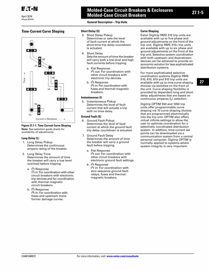
CA08104001E For more information, visit: www.eaton.com/consultants
27.1-5April 2016
Molded-Case Circuit Breakers & Enclosures
Sheet 27
22
23
24
25
26
27
28
29
30
31
32
33
34
35
36
37
38
39
40
41
42
43
Molded-Case Circuit BreakersGeneral Description—Trip Units
009
Time-Current Curve Shaping
Figure 27.1-1. Time-Current Curve ShapingNote: See selection guide charts for availability of adjustments.
Long Delay (L)1. Long Delay Pickup
Determines the continuous ampere rating of the breaker.
2. Long Delay Time Determines the amount of time the breaker will carry a low level overload before tripping.
a. I2t ResponseI2t in: For coordination with other circuit breakers with electronic trip devices and for coordination with thermal-magnetic circuit breakers.
b. I4t ResponseI4t in: For coordination with fuses and upstream trans-former damage curves.
7B
7A
6
Tim
e
5
1
4B
4A
2A
2B2
3
Current in Multiples
4
7
Short Delay (S)3. Short Delay Pickup
Determines or sets the level of fault current at which the short-time trip delay countdown is actuated.
4. Short DelaySets the amount of time the breaker will carry both a low level and high fault currents before tripping.
a. Flat ResponseI2t out: For coordination with other circuit breakers with electronic trip devices.
b. I2t ResponseI2t in: For coordination with fuses and thermal-magnetic breakers.
Instantaneous (I)5. Instantaneous Pickup
Determines the level of fault current that will actuate a trip with no time delay.
Ground Fault (G)6. Ground Fault Pickup
Determines the level of fault current at which the ground fault trip delay countdown is actuated.
7. Ground Fault DelayDetermines the amount of time the breaker will carry a ground fault before tripping.
a. Flat ResponseI2t out: For coordination with other circuit breakers with electronic ground fault settings.
b. I2t ResponseI2t in: For coordination with zero sequence ground fault relays, fuses and thermal-magnetic breakers.
Curve Shaping Eaton Digitrip RMS 310 trip units are available with up to five phase and ground adjustments on the front of the trip unit. Digitrip RMS 310+ trip units are available with up to six phase and ground adjustments on the front of the trip unit. Selective system coordination with both upstream and downstream devices can be achieved to provide an economic solution for less sophisticated distribution systems.
For more sophisticated selective coordination systems Digitrip RMS 510, 610, 810 and 910 trip units are available with up to nine curve shaping choices via switches on the front of the unit. Curve shaping flexibility is provided by dependent long and short delay adjustments that are based on continuous amperes (Ir) selection.
Digitrip OPTIM 550 and 1050 trip units offer programmable curve shaping via 10 curve shaping choices that are programmed electronically into the trip unit. OPTIM also offers virtual infinite settings to allow the user to optimize coordination for a selectively coordinated distribution system. In addition, time-current set points can be downloaded via a communication system from a central personal computer. Digitrip OPTIM is normally applied to systems where system integrity is very important.
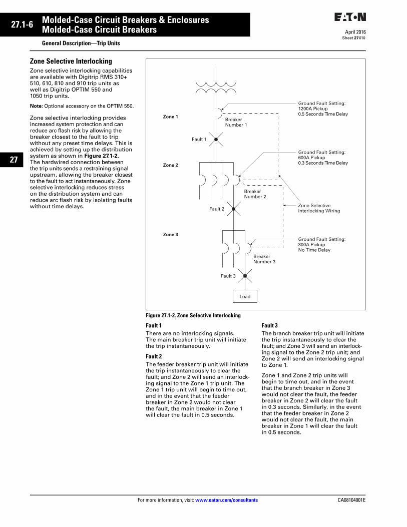
27.1-6
For more information, visit: www.eaton.com/consultants CA08104001E
April 2016
Molded-Case Circuit Breakers & Enclosures
Sheet 27
22
23
24
25
26
27
28
29
30
31
32
33
34
35
36
37
38
39
40
41
42
43
Molded-Case Circuit BreakersGeneral Description—Trip Units
010
Zone Selective InterlockingZone selective interlocking capabilities are available with Digitrip RMS 310+510, 610, 810 and 910 trip units as well as Digitrip OPTIM 550 and 1050 trip units.
Note: Optional accessory on the OPTIM 550.
Zone selective interlocking provides increased system protection and can reduce arc flash risk by allowing the breaker closest to the fault to trip without any preset time delays. This is achieved by setting up the distribution system as shown in Figure 27.1-2. The hardwired connection between the trip units sends a restraining signal upstream, allowing the breaker closest to the fault to act instantaneously. Zone selective interlocking reduces stress on the distribution system and can reduce arc flash risk by isolating faults without time delays.
Figure 27.1-2. Zone Selective Interlocking
Fault 1There are no interlocking signals. The main breaker trip unit will initiate the trip instantaneously.
Fault 2The feeder breaker trip unit will initiate the trip instantaneously to clear the fault; and Zone 2 will send an interlock-ing signal to the Zone 1 trip unit. The Zone 1 trip unit will begin to time out, and in the event that the feeder breaker in Zone 2 would not clear the fault, the main breaker in Zone 1 will clear the fault in 0.5 seconds.
Fault 3The branch breaker trip unit will initiate the trip instantaneously to clear the fault; and Zone 3 will send an interlock-ing signal to the Zone 2 trip unit; and Zone 2 will send an interlocking signal to Zone 1.
Zone 1 and Zone 2 trip units will begin to time out, and in the event that the branch breaker in Zone 3 would not clear the fault, the feeder breaker in Zone 2 will clear the fault in 0.3 seconds. Similarly, in the event that the feeder breaker in Zone 2 would not clear the fault, the main breaker in Zone 1 will clear the fault in 0.5 seconds.
Zone 1
Zone 2
Zone 3
Fault 1
Fault 2
Fault 3
Load
BreakerNumber 1
BreakerNumber 2
BreakerNumber 3
Ground Fault Setting:300A PickupNo Time Delay
Zone SelectiveInterlocking Wiring
Ground Fault Setting:600A Pickup0.3 Seconds Time Delay
Ground Fault Setting:1200A Pickup0.5 Seconds Time Delay

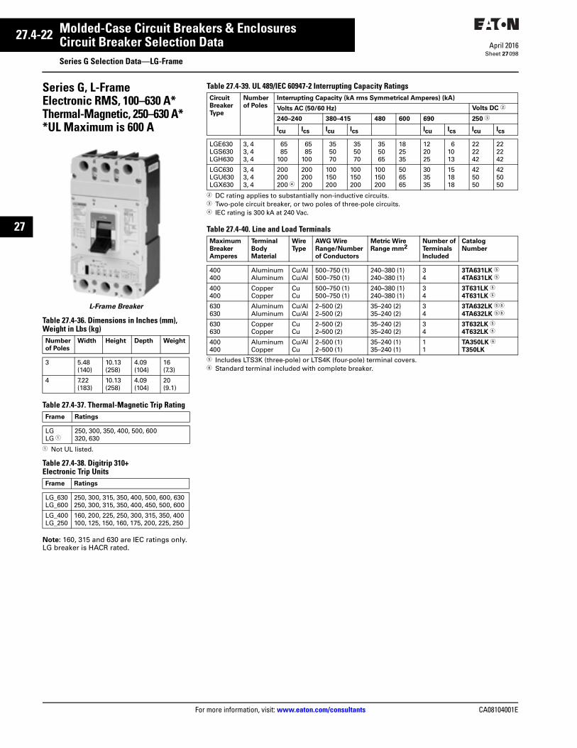
27.4-22
For more information, visit: www.eaton.com/consultants CA08104001E
April 2016
Molded-Case Circuit Breakers & Enclosures
Sheet 27
27
Circuit Breaker Selection DataSeries G Selection Data—LG-Frame
098
Series G, L-FrameElectronic RMS, 100–630 A*Thermal-Magnetic, 250–630 A**UL Maximum is 600 A
L-Frame Breaker
Table 27.4-36. Dimensions in Inches (mm), Weight in Lbs (kg)
Table 27.4-37. Thermal-Magnetic Trip Rating
1 Not UL listed.
Table 27.4-38. Digitrip 310+ Electronic Trip Units
Note: 160, 315 and 630 are IEC ratings only. LG breaker is HACR rated.
Number
of Poles
Width Height Depth Weight
3 5.48(140)
10.13(258)
4.09(104)
16(7.3)
4 7.22(183)
10.13(258)
4.09(104)
20(9.1)
Frame Ratings
LGLG 1
250, 300, 350, 400, 500, 600320, 630
Frame Ratings
LG_630LG_600
250, 300, 315, 350, 400, 500, 600, 630250, 300, 315, 350, 400, 450, 500, 600
LG_400LG_250
160, 200, 225, 250, 300, 315, 350, 400100, 125, 150, 160, 175, 200, 225, 250
Table 27.4-39. UL 489/IEC 60947-2 Interrupting Capacity Ratings
2 DC rating applies to substantially non-inductive circuits.3 Two-pole circuit breaker, or two poles of three-pole circuits.4 IEC rating is 300 kA at 240 Vac.
Table 27.4-40. Line and Load Terminals
5 Includes LTS3K (three-pole) or LTS4K (four-pole) terminal covers.6 Standard terminal included with complete breaker.
Circuit
Breaker
Type
Number
of Poles
Interrupting Capacity (kA rms Symmetrical Amperes) (kA)
Volts AC (50/60 Hz) Volts DC 2
240–240 380–415 480 600 690 250 3
Icu Ics Icu Ics Icu Ics Icu Ics
LGE630LGS630LGH630
3, 43, 43, 4
6585
100
6585
100
355070
355070
355065
182535
122025
61013
222242
222242
LGC630LGU630LGX630
3, 43, 43, 4
200200200 4
200200200
100150200
100150200
100150200
506565
303535
151818
425050
425050
Maximum
Breaker
Amperes
Terminal
Body
Material
Wire
Type
AWG Wire
Range/Number
of Conductors
Metric Wire
Range mm2Number of
Terminals
Included
Catalog
Number
400400
AluminumAluminum
Cu/AlCu/Al
500–750 (1)500–750 (1)
240–380 (1)240–380 (1)
34
3TA631LK 5
4TA631LK 5
400400
CopperCopper
CuCu
500–750 (1)500–750 (1)
240–380 (1)240–380 (1)
34
3T631LK 5
4T631LK 5
630630
AluminumAluminum
Cu/AlCu/Al
2–500 (2)2–500 (2)
35–240 (2)35–240 (2)
34
3TA632LK 56
4TA632LK 56
630630
CopperCopper
CuCu
2–500 (2)2–500 (2)
35–240 (2)35–240 (2)
34
3T632LK 5
4T632LK 5
400400
AluminumCopper
Cu/AlCu
2–500 (1)2–500 (1)
35–240 (1)35–240 (1)
11
TA350LK 6
T350LK


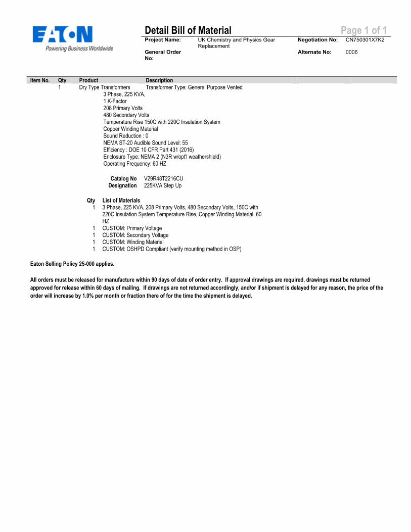
Detail Bill of Material Page 1 of 1
Project Name: UK Chemistry and Physics Gear Replacement
Negotiation No: CN750301X7K2
General Order No:
Alternate No: 0006
Item No. Qty Product Description 1 Dry Type Transformers Transformer Type: General Purpose Vented 3 Phase, 225 KVA, 1 K-Factor 208 Primary Volts 480 Secondary Volts Temperature Rise 150C with 220C Insulation System Copper Winding Material Sound Reduction : 0 NEMA ST-20 Audible Sound Level: 55 Efficiency : DOE 10 CFR Part 431 (2016) Enclosure Type: NEMA 2 (N3R w/opt'l weathershield) Operating Frequency: 60 HZ
Catalog No V29R48T2216CU Designation 225KVA Step Up
Qty List of Materials 1 3 Phase, 225 KVA, 208 Primary Volts, 480 Secondary Volts, 150C with
220C Insulation System Temperature Rise, Copper Winding Material, 60 HZ
1 CUSTOM: Primary Voltage 1 CUSTOM: Secondary Voltage 1 CUSTOM: Winding Material 1 CUSTOM: OSHPD Compliant (verify mounting method in OSP)
Eaton Selling Policy 25-000 applies.
All orders must be released for manufacture within 90 days of date of order entry. If approval drawings are required, drawings must be returned
approved for release within 60 days of mailing. If drawings are not returned accordingly, and/or if shipment is delayed for any reason, the price of the
order will increase by 1.0% per month or fraction there of for the time the shipment is delayed.

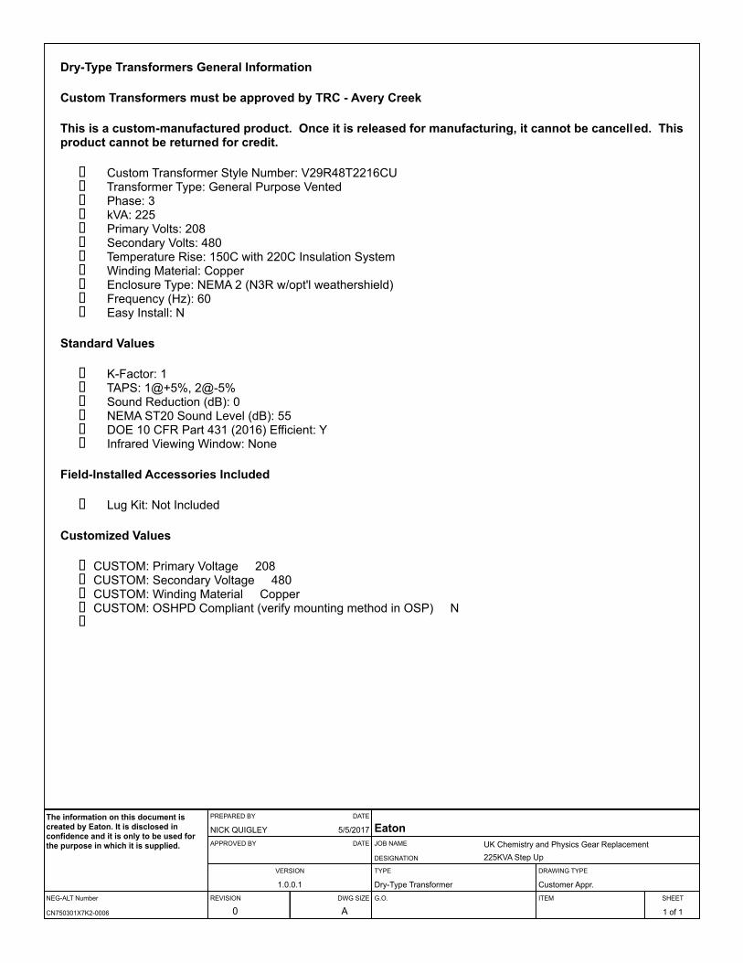
Dry-Type Transformers General Information
Custom Transformers must be approved by TRC - Avery Creek
This is a custom-manufactured product. Once it is released for manufacturing, it cannot be cancelled. This product cannot be returned for credit.
Custom Transformer Style Number: V29R48T2216CUTransformer Type: General Purpose VentedPhase: 3kVA: 225Primary Volts: 208Secondary Volts: 480Temperature Rise: 150C with 220C Insulation SystemWinding Material: CopperEnclosure Type: NEMA 2 (N3R w/opt'l weathershield)Frequency (Hz): 60Easy Install: N
Standard Values
K-Factor: 1TAPS: 1@+5%, 2@-5%Sound Reduction (dB): 0NEMA ST20 Sound Level (dB): 55DOE 10 CFR Part 431 (2016) Efficient: YInfrared Viewing Window: None
Field-Installed Accessories Included
Lug Kit: Not Included
Customized Values
CUSTOM: Primary Voltage 208CUSTOM: Secondary Voltage 480CUSTOM: Winding Material CopperCUSTOM: OSHPD Compliant (verify mounting method in OSP) N
NEG-ALT Number
PREPARED BY DATE
APPROVED BY DATE
VERSION
REVISION DWG SIZE
JOB NAME
DESIGNATION
TYPE
G.O.
DRAWING TYPE
ITEM SHEET
The information on this document is created by Eaton. It is disclosed in confidence and it is only to be used for the purpose in which it is supplied.
CN750301X7K2-0006
NICK QUIGLEY 5/5/2017
1.0.0.1
0 A
EatonUK Chemistry and Physics Gear Replacement225KVA Step Up
Dry-Type Transformer Customer Appr.
1 of 1
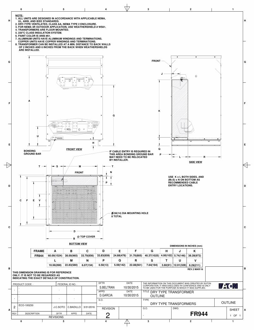
1
1
2
2
3
3
4
4
5
5
6
6
A A
B B
C C
D D
E E
F F
G G
H H
PRODUCT CODE: FEDERAL ID NO.
REV DESCRIPTION DFTR APPD DATE
REVISIONSFR944
DFTR DATE
APPD DATE
S.O.
REVISION
THE INFORMATION ON THIS DOCUMENT WAS CREATED BY EATON
CORPORATION. IT WAS DISCLOSED IN CONFIDENCE AND IS ONLY
TO BE USED FOR THE PURPOSE IN WHICH IT WAS SUPPLIED.
TITLE
TYPE
G.O. DWGSHEET
2
10/30/2015S.BELTRAN
D.GARCIA 10/30/2015
1 OF.
DRY TYPE TRANSFORMER
OUTLINE
1
. DRY TYPE TRANSFORMERS OUTLINE
2
.
ECO-100230
.
..
.
.
.
J.C.SOTO
.
.
C.BADILLO
.
.
3/31/2016
. .
FRONT VIEW
SIDE VIEW
BOTTOM VIEW
@ TOP COVER
NOTE:1. ALL UNITS ARE DESIGNED IN ACCORDANCE WITH APPLICABLE NEMA, UL, ANSI, AND IEEE STANDARDS.2. DRY-TYPE VENTILATED, CLASS AA, NEMA TYPE 2 ENCLOSURE.3. FOR NEMA 3R OUTDOOR APPLICATION, USE WEATHERSHIELD # WS61.4. TRANSFORMERS ARE FLOOR MOUNTED.
5. 220°C CLASS INSULATION SYSTEM.
6. PAINT COLOR IS ANSI #61.7. ALUMINUM UNITS HAVE ALUMINUM WINDINGS AND TERMINATIONS. COPPER UNITS HAVE COPPER WINDINGS AND TERMINATIONS.8. TRANSFORMER CAN BE INSTALLED AT A MIN. DISTANCE TO BACK WALLS OF 2 INCHES AND 6 INCHES FROM THE BACK WHEN WEATHERSHIELDS ARE INSTALLED.
THIS DIMENSION DRAWING IS FOR REFERENCEONLY. IT IS NOT TO BE REGARDED ASINDICATING THE EXACT DETAILS OF CONSTRUCTION.
USE K x L BOTH SIDES, AND (M+S) x N ON BOTTOM AS RECOMMENDED CABLE ENTRY LOCATIONS.
FRAME A
31.70(805)
E F
S
G
7.64(194)
FR944
10.56(268)
L
60.00(1524) 24.88(478)
Q
5.59(142) 22.08(561)
R
40.37(1025) 4.00(102) 5.74(146)
T
B
38.00(965)
M
22.83(580) 6.07(154)
N
33.70(856)
C D
33.83(859)
P
0.50(13)
H J
3.60(91)
DIMENSIONS IN INCHES (mm)
K
38.28(972)
U
12.91(328)
REV.2 MAR/16
8.29(211)
V
LC
FRONT
FRONT
H
U
G
A
X0
J
K
Q
PL R
C
B
M
N
T T S
IF CABLE ENTRY IS REQUIRED IN THIS AREA BONDING GROUND BAR MAY NEED TO BE RELOCATED BY INSTALLER.
BONDING GROUND BAR
P
E VF
nnnn.56(14) DIA MOUNTING HOLE
8 TOTAL
D
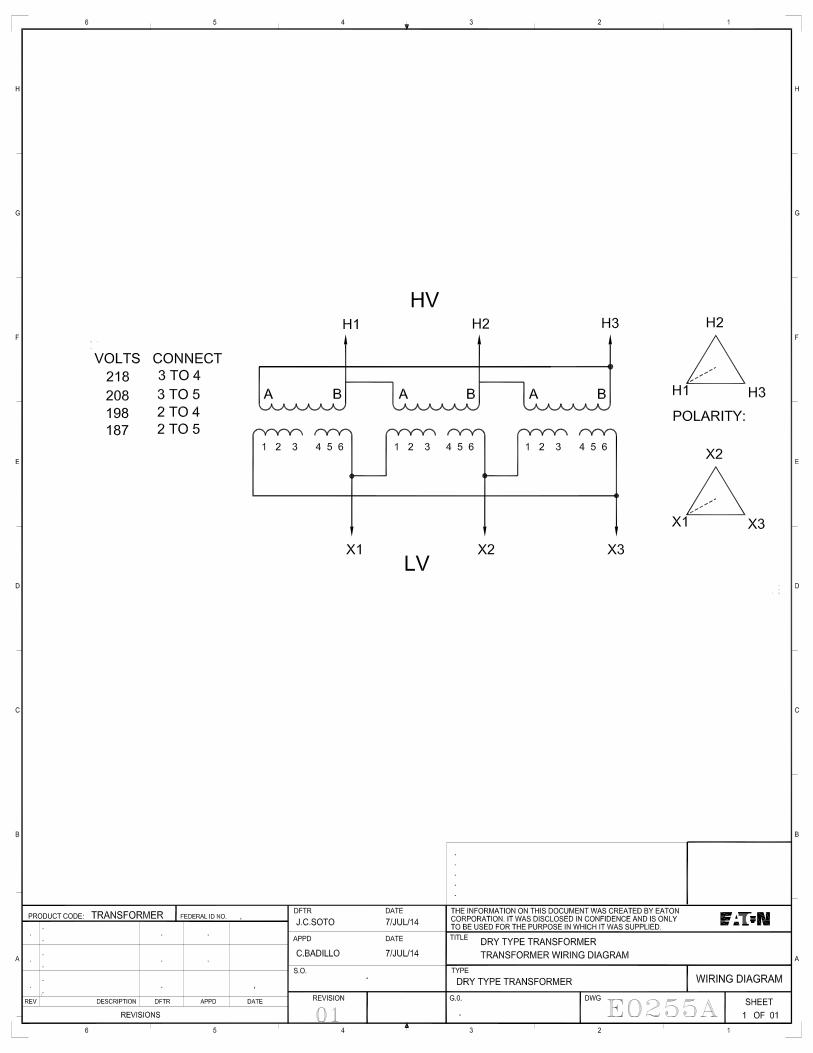

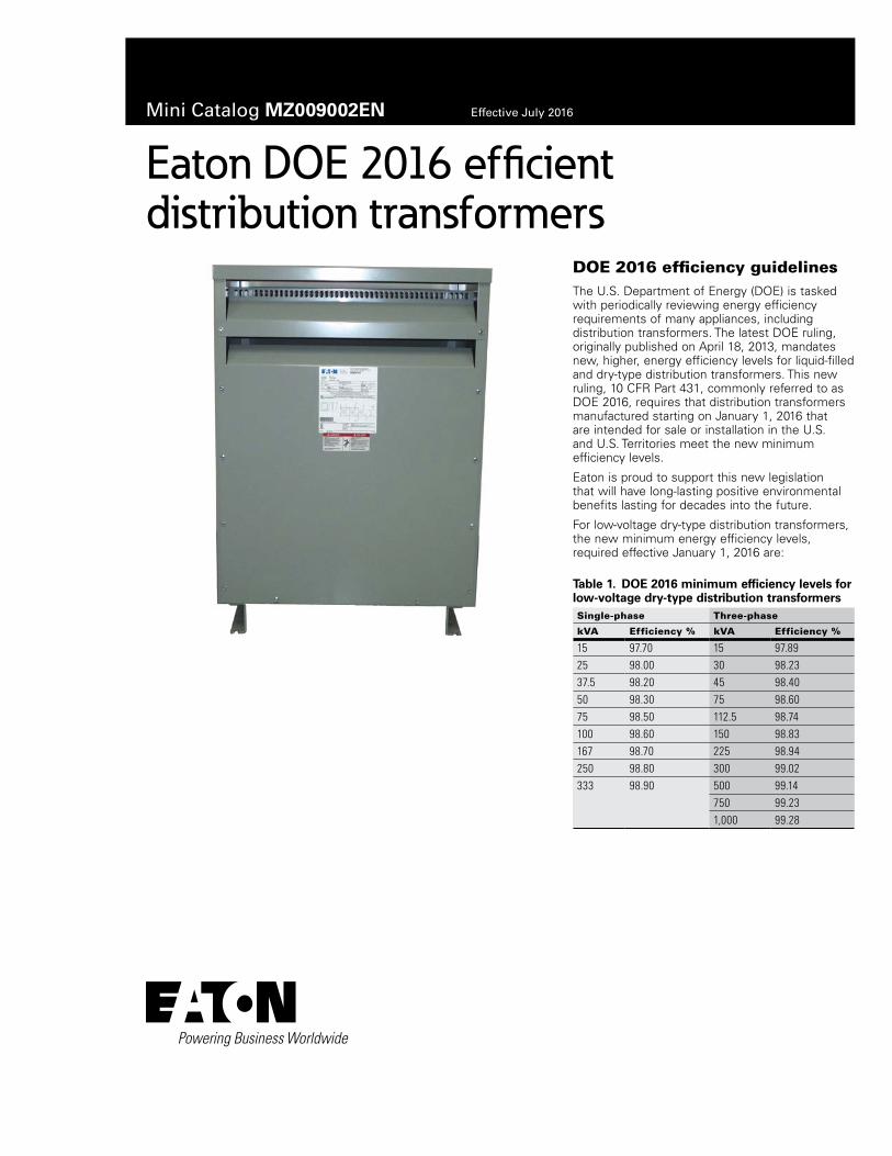
Mini Catalog MZ009002EN Effective July 2016
Eaton DOE 2016 efficient distribution transformers
DOE 2016 efficiency guidelinesThe U.S. Department of Energy (DOE) is tasked with periodically reviewing energy efficiency requirements of many appliances, including distribution transformers. The latest DOE ruling, originally published on April 18, 2013, mandates new, higher, energy efficiency levels for liquid-filled and dry-type distribution transformers. This new ruling, 10 CFR Part 431, commonly referred to as DOE 2016, requires that distribution transformers manufactured starting on January 1, 2016 that are intended for sale or installation in the U.S. and U.S. Territories meet the new minimum efficiency levels.
Eaton is proud to support this new legislation that will have long-lasting positive environmental benefits lasting for decades into the future.
For low-voltage dry-type distribution transformers, the new minimum energy efficiency levels, required effective January 1, 2016 are:
Table 1. DOE 2016 minimum efficiency levels for low-voltage dry-type distribution transformersSingle-phase Three-phase
kVA Efficiency % kVA Efficiency %
15 97.70 15 97.8925 98.00 30 98.2337.5 98.20 45 98.4050 98.30 75 98.6075 98.50 112.5 98.74100 98.60 150 98.83167 98.70 225 98.94250 98.80 300 99.02333 98.90 500 99.14
750 99.231,000 99.28
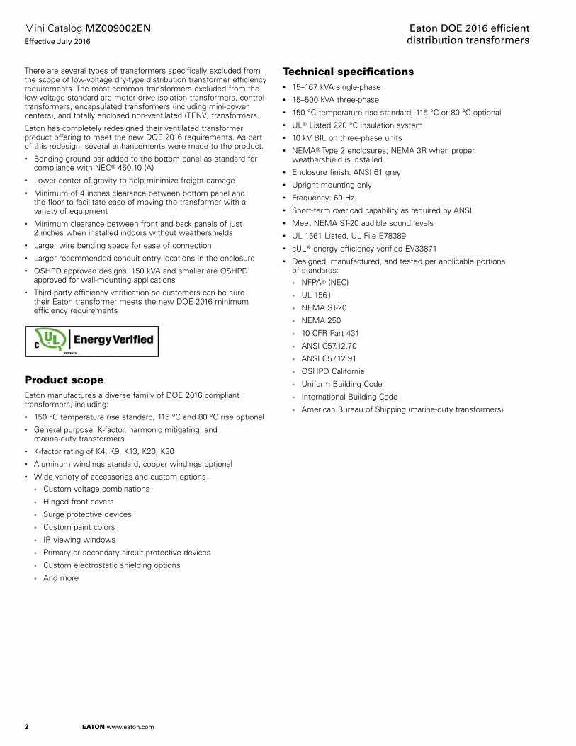
2
Mini Catalog MZ009002ENEffective July 2016
Eaton DOE 2016 effi cient distribution transformers
EATON www.eaton.com
There are several types of transformers specifically excluded from the scope of low-voltage dry-type distribution transformer efficiency requirements. The most common transformers excluded from the low-voltage standard are motor drive isolation transformers, control transformers, encapsulated transformers (including mini-power centers), and totally enclosed non-ventilated (TENV) transformers.
Eaton has completely redesigned their ventilated transformer product offering to meet the new DOE 2016 requirements. As part of this redesign, several enhancements were made to the product.• Bonding ground bar added to the bottom panel as standard for
compliance with NECT 450.10 (A)• Lower center of gravity to help minimize freight damage• Minimum of 4 inches clearance between bottom panel and
the floor to facilitate ease of moving the transformer with a variety of equipment
• Minimum clearance between front and back panels of just 2 inches when installed indoors without weathershields
• Larger wire bending space for ease of connection• Larger recommended conduit entry locations in the enclosure• OSHPD approved designs. 150 kVA and smaller are OSHPD
approved for wall-mounting applications• Third-party efficiency verification so customers can be sure
their Eaton transformer meets the new DOE 2016 minimum efficiency requirements
Product scopeEaton manufactures a diverse family of DOE 2016 compliant transformers, including:• 150 °C temperature rise standard, 115 °C and 80 °C rise optional• General purpose, K-factor, harmonic mitigating, and
marine-duty transformers• K-factor rating of K4, K9, K13, K20, K30• Aluminum windings standard, copper windings optional• Wide variety of accessories and custom options
• Custom voltage combinations
• Hinged front covers
• Surge protective devices
• Custom paint colors
• IR viewing windows
• Primary or secondary circuit protective devices
• Custom electrostatic shielding options
• And more
Technical specifi cations• 15–167 kVA single-phase• 15–500 kVA three-phase• 150 °C temperature rise standard, 115 °C or 80 °C optional• ULT Listed 220 °C insulation system• 10 kV BIL on three-phase units• NEMAT Type 2 enclosures; NEMA 3R when proper
weathershield is installed• Enclosure finish: ANSI 61 grey• Upright mounting only• Frequency: 60 Hz• Short-term overload capability as required by ANSI• Meet NEMA ST-20 audible sound levels• UL 1561 Listed, UL File E78389• cULT energy efficiency verified EV33871• Designed, manufactured, and tested per applicable portions
of standards:• NFPAT (NEC)
• UL 1561
• NEMA ST-20
• NEMA 250
• 10 CFR Part 431
• ANSI C57.12.70
• ANSI C57.12.91
• OSHPD California
• Uniform Building Code
• International Building Code
• American Bureau of Shipping (marine-duty transformers)
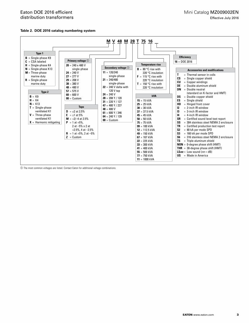
3
Mini Catalog MZ009002ENEffective July 2016
Eaton DOE 2016 efficient distribution transformers
EATON www.eaton.com
Table 2. DOE 2016 catalog numbering system
aThe most common voltages are listed. Contact Eaton for additional voltage combinations.
M V 48 M 28 T 75 16
Type 1
B = Single-phase K9C = CSA labeledH = Single-phase K4N = Single-phase K13M = Three-phase marine dutyR = Single-phase marine duty
Primary voltage a
20 = 240 x 480 V single-phase24 = 240 V27 = 277 V29 = 208 V38 = 380 V48 = 480 V57 = 575 V60 = 600 V00 = Custom
Type 2
B = K9H = K4N = K13T = Single-phase ventilated K1V = Three-phase ventilated K1X = Harmonic mitigating
Taps
D = ±2 at 2.5%E = ±1 at 5%M = +2/–4 at 2.5%P = 1 at +5%, 2 at –5% x 2 at +2.5%, 4 at –2.5%R = 1 at +5%, 2 at –5%Z = Custom
Secondary voltage a
11 = 120/240 single-phase21 = 240/480 single-phase22 = 240 V delta with 120 V tap24 = 240 V28 = 208 Y / 12031 = 220 Y / 12747 = 480 Y / 22748 = 480 V61 = 600 Y / 34664 = 240 Y / 13900 = Custom
Temperature rise
B = 80 °C rise with 220 °C insulationF = 115 °C rise with 220 °C insulationT = 150 °C rise with 220 °C insulation
kVA
15 = 15 kVA25 = 25 kVA30 = 30 kVA37 = 37.5 kVA45 = 45 kVA50 = 50 kVA75 = 75 kVA99 = 100 kVA12 = 112.5 kVA49 = 150 kVA67 = 167 kVA22 = 225 kVA 33 = 300 kVA41 = 400 kVA55 = 500 kVA77 = 750 kVA11 = 1000 kVA
Efficiency
16 = DOE 2016
Accessories and modifications
T = Thermal sensor in coilsCS = Single copper shieldCU = Copper windingsDE = Double aluminum shieldDN = Double neutral (standard on K-factor and HMT)DS = Double copper shieldES = Single shieldHD = Hinged front coverI2 = 2-inch IR windowI3 = 3-inch IR windowI4 = 4-inch IR windowSR = Certified sound level test reportSS = 304 stainless steel NEMA 2 enclosureTR = Certified production test reportS2 = 80 kA per mode SPDS3 = 160 kA per mode SPDS6 = 316 stainless steel NEMA 2 enclosureTS = Triple aluminum shieldNON = 0-degree phase shift (HMT)THR = 30-degree phase shift (HMT)LSnn = Low sound (nn = dB)US = Made in America
4
Mini Catalog MZ009002ENEffective July 2016
Eaton DOE 2016 efficient distribution transformers
EATON www.eaton.com
General construction features of DOE 2016 efficient transformers rated 600 V and belowGeneral description
Eaton’s single-phase and three-phase general purpose dry-type ventilated transformers are of the two-winding type, self-cooled, and are available in a variety of primary and secondary voltage combinations.
Eaton’s transformers are designed, manufactured, and tested in accordance with all of the latest applicable ANSI, NEMA, and IEEET standards. All 600 V class ventilated transformers with ratings through 1500 kVA are UL listed and bear the UL label. Open core and coil assemblies are UL recognized (UR) labeled products.
These transformers are designed for continuous operation at rated kVA for 24 hours a day, 365 days a year, with a normal life expectancy as defined in ANSI C57.96.
Efficiency validation
Eaton-manufactured transformers in compliance with 10 CFR Part 431 (2016), “DOE 2016 efficient” bear the UL Energy Efficiency Verification Mark to confirm that the transformer meets the minimum energy efficiency requirements set forth in federal law 10 CFR Part 431.
Insulation system
The design life of transformers having different insulation systems is the same; the lower temperature systems are designed to have the same life as the higher rated temperature systems.
Most Eaton ventilated transformers, regardless of their temperature rise, are manufactured using a 220 °C insulation system. Required performance is obtained without exceeding the insulation system rating at rated temperature rise in a 40 °C maximum ambient, with an average of 30 °C over a 24-hour period. Transformers manufactured with 220 °C insulation system meet the requirements of NEC 450.21(b) Exception No. 2. It is not necessary to install them in a special, fire-resistant room.
All insulation materials used are flame-retardant and do not support combustion, as defined in ASTM Standard Test Method D635.
Core and coil assemblies
The transformer core is constructed using high-grade, non-aging, silicon steel with high magnetic permeability, and low hysteresis and eddy current losses. Maximum magnetic flux densities are substantially below the saturation point. The transformer core volume allows for efficient transformer operation at 10% above the nominal tap voltage. The core laminations are tightly clamped and compressed. The BIL (basic impulse level) for all 600 V-class windings is 10 kV. The core and coil assembly is installed on neoprene vibration-absorbing pads. Coils are treated with a varnish that does not support the growth of fungus.
Ventilated transformers with wye-connected secondaries have the neutral brought out to a separate terminal or busbar.
The core and coil assembly is grounded to the transformer enclosure by means of a flexible copper ground strap. The copper ground strap is sized per the NEC to be a grounding conductor.
Eaton three-phase DOE 2016 efficient transformers are provided with a bonding ground bar attached to the bottom panel for compliance with NEC 450.10(A).
Electrostatic shielding
There are no industry standards for electrostatic shield performance. Eaton-manufactured transformers have been tested by an independent laboratory to meet the following attenuation levels:
When tested per MIL-Std-220A, Method Of Insertion Loss Measurement, with matched impedance no load technique:• Common mode noise attenuation:
Minus 80 dBA minimum at 0.1 kHz to 1.5 kHz; minus 55 dBA minimum at 1.51 kHz to 100 kHz
• Normal mode (transverse mode) noise attenuation: Minus 30 dBA minimum at 1.5 kHz to 10 kHz.
Primary to secondary capacitance of 24.74 to 18.06 picofarads over the range 100 to 20 kHz.
Taps
Primary taps are available on most Eaton ventilated transformers to allow compensation for source voltage variations.
Winding terminations
Primary and secondary windings are terminated in the wiring compartment. Ventilated transformers have leads brought out to aluminum or copper pads that are pre-drilled to accept Al/Cu lugs. Aluminum-wound transformers have aluminum pads; copper-wound transformers have copper pads. Lugs are not supplied with Eaton transformers; however, lug kits are available as a field-installed accessory. Eaton recommends external cables be rated 75 °C for ventilated designs.
Enclosures
The transformer enclosure is made of heavy-gauge steel and is finished using a continuous process of degreasing, cleaning, and phosphatizing, followed by electrostatic deposition of a thermosetting polyester powder coating and subsequent baking. The coating color is ANSI 61 grey and is UL-recognized for indoor or outdoor use. In compliance with NEMA ST-20, Eaton’s ventilated transformers are designed such that the maximum temperature on the top of the enclosure does not exceed 50 °C rise above the ambient temperature.
For ventilated transformers, the enclosure standard construction is drip-proof, NEMA 2, with lifting provisions on the top of the core. All ventilation openings are protected against falling dirt. Proper installation of weathershields makes the enclosure NEMA 3R rated and suitable for outdoor use.
To ensure proper ventilation and cooling of the transformer, follow manufacturer’s recommended clearance around ventilation openings.
Installation clearances
Eaton’s transformers should be installed with a minimum clearance around the transformer enclosure to prevent accidental contact with flammable or combustible materials.
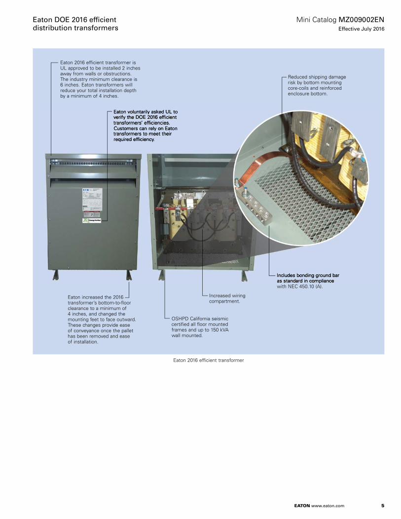
5
Mini Catalog MZ009002ENEffective July 2016
Eaton DOE 2016 effi cient distribution transformers
EATON www.eaton.com
Eaton 2016 efficient transformer is UL approved to be installed 2 inches away from walls or obstructions. The industry minimum clearance is 6 inches. Eaton transformers will reduce your total installation depth by a minimum of 4 inches.
Eaton voluntarily asked UL to verify the DOE 2016 efficient transformers’ efficiencies. Customers can rely on Eaton transformers to meet their required efficiency.
Reduced shipping damage risk by bottom mounting core-coils and reinforced enclosure bottom.
Includes bonding ground bar as standard in compliance with NEC 450.10 (A).
Increased wiring compartment.
OSHPD California seismic certified all floor mounted frames and up to 150 kVA wall mounted.
Eaton increased the 2016 transformer’s bottom-to-floor clearance to a minimum of 4 inches, and changed the mounting feet to face outward. These changes provide ease of conveyance once the pallet has been removed and ease of installation.
Eaton voluntarily asked UL to verify the DOE 2016 efficient transformers’ efficiencies. Customers can rely on Eaton transformers to meet their required efficiency.
Includes bonding ground bar as standard in compliance
Eaton 2016 efficient transformer
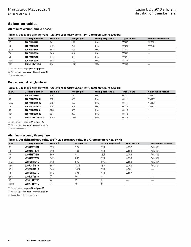
6
Mini Catalog MZ009002ENEffective July 2016
Eaton DOE 2016 efficient distribution transformers
EATON www.eaton.com
Selection tablesAluminum wound, single-phase,
Table 3. 240 x 480 primary volts, 120/240 secondary volts, 150 °C temperature rise, 60 HzkVA Catalog number Frame a Weight (lb) Wiring diagram b Type 3R WS Wallmount bracket
15 T20P11S1516 842 196 3XA WS45 WMB0125 T20P11S2516 842 261 3XA WS45 WMB0137.5 T20P11S3716 843 304 3XA WS43 —50 T20P11S5016 843 410 3XA WS43 —75 T20P11S7516 844 688 3XA WS44 —100 T20P11S9916 844 699 3XA WS44 —167 T48M11S6716 c 814 1294 288A WS13 —
aFrame drawings on page 14 and page 15.bWiring diagrams on page 16 through page 20.c480 V primary only.
Copper wound, single-phase
Table 4. 240 x 480 primary volts, 120/240 secondary volts, 150 °C temperature rise, 60 HzkVA Catalog number Frame a Weight (lb) Wiring diagram b Type 3R WS Wallmount bracket
15 T20P11S1516CU 816 270 3XA WS11 WMB0125 T20P11S2516CU 818 406 3XA WS11 WMB0137.5 T20P11S3716CU 818 453 3XA WS11 WMB0150 T20P11S5016CU 819 657 3XA WS16 WMB0175 T20P11S7516CU 820 803 3XA WS16 —100 T20P11S9916CU 821 960 3XA WS13 —167 T48M11S6716CU c 814E 1665 288A WS13 —
aFrame drawings on page 14 and page 15.bWiring diagrams on page 16 through page 20.c480 V primary only.
Aluminum wound, three-phase
Table 5. 208 delta primary volts, 208Y/120 secondary volts, 150 °C temperature rise, 60 HzkVA Catalog number Frame a Weight (lb) Wiring diagram b Type 3R WS Wallmount bracket
15 V29M28T1516 939 225 280E WS57 WMB0530 V29M28T3016 940 409 280E WS58 WMB0545 V29M28T4516 940 416 280E WS58 WMB0575 V29M28T7516 942 602 280E WS59 WMB04112.5 V29R28T1216 943 976 324A WS60 WMB04150 V29R28T4916 943 1239 324A WS60 WMB04225 V29R28T2216 944 1624 289D WS61 —300 V29R28T3316 945 2283 289D WS62 —500 V29E28T5516 c c c — —750 V29N28T7716 c c c — —1000 V29N28T1116 c c c — —
aFrame drawings on page 14 and page 15.bWiring diagrams on page 16 through page 20.cContact local Eaton representative.
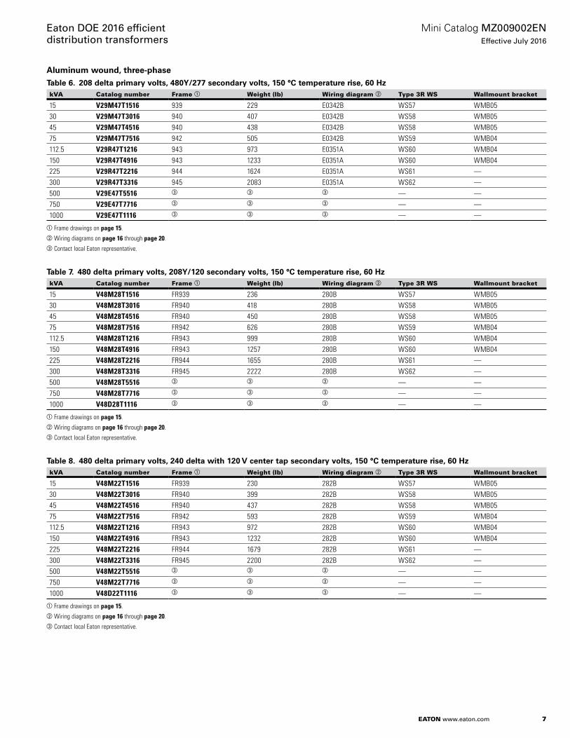
7
Mini Catalog MZ009002ENEffective July 2016
Eaton DOE 2016 efficient distribution transformers
EATON www.eaton.com
Aluminum wound, three-phase
Table 6. 208 delta primary volts, 480Y/277 secondary volts, 150 °C temperature rise, 60 HzkVA Catalog number Frame a Weight (lb) Wiring diagram b Type 3R WS Wallmount bracket
15 V29M47T1516 939 229 E0342B WS57 WMB0530 V29M47T3016 940 407 E0342B WS58 WMB0545 V29M47T4516 940 438 E0342B WS58 WMB0575 V29M47T7516 942 505 E0342B WS59 WMB04112.5 V29R47T1216 943 973 E0351A WS60 WMB04150 V29R47T4916 943 1233 E0351A WS60 WMB04225 V29R47T2216 944 1624 E0351A WS61 —300 V29R47T3316 945 2083 E0351A WS62 —500 V29E47T5516 c c c — —750 V29E47T7716 c c c — —1000 V29E47T1116 c c c — —
aFrame drawings on page 15.bWiring diagrams on page 16 through page 20.cContact local Eaton representative.
Table 7. 480 delta primary volts, 208Y/120 secondary volts, 150 °C temperature rise, 60 HzkVA Catalog number Frame a Weight (lb) Wiring diagram b Type 3R WS Wallmount bracket
15 V48M28T1516 FR939 236 280B WS57 WMB0530 V48M28T3016 FR940 418 280B WS58 WMB0545 V48M28T4516 FR940 450 280B WS58 WMB0575 V48M28T7516 FR942 626 280B WS59 WMB04112.5 V48M28T1216 FR943 999 280B WS60 WMB04150 V48M28T4916 FR943 1257 280B WS60 WMB04225 V48M28T2216 FR944 1655 280B WS61 —300 V48M28T3316 FR945 2222 280B WS62 —500 V48M28T5516 c c c — —750 V48M28T7716 c c c — —1000 V48D28T1116 c c c — —
aFrame drawings on page 15.bWiring diagrams on page 16 through page 20.cContact local Eaton representative.
Table 8. 480 delta primary volts, 240 delta with 120 V center tap secondary volts, 150 °C temperature rise, 60 HzkVA Catalog number Frame a Weight (lb) Wiring diagram b Type 3R WS Wallmount bracket
15 V48M22T1516 FR939 230 282B WS57 WMB0530 V48M22T3016 FR940 399 282B WS58 WMB0545 V48M22T4516 FR940 437 282B WS58 WMB0575 V48M22T7516 FR942 593 282B WS59 WMB04112.5 V48M22T1216 FR943 972 282B WS60 WMB04150 V48M22T4916 FR943 1232 282B WS60 WMB04225 V48M22T2216 FR944 1679 282B WS61 —300 V48M22T3316 FR945 2200 282B WS62 —500 V48M22T5516 c c c — —750 V48M22T7716 c c c — —1000 V48D22T1116 c c c — —
aFrame drawings on page 15.bWiring diagrams on page 16 through page 20.cContact local Eaton representative.
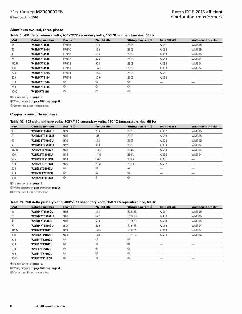
8
Mini Catalog MZ009002ENEffective July 2016
Eaton DOE 2016 efficient distribution transformers
EATON www.eaton.com
Aluminum wound, three-phase
Table 9. 480 delta primary volts, 480Y/277 secondary volts, 150 °C temperature rise, 60 HzkVA Catalog number Frame a Weight (lb) Wiring diagram b Type 3R WS Wallmount bracket
15 V48M47T1516 FR939 208 280B WS57 WMB0530 V48M47T3016 FR940 395 280B WS58 WMB0545 V48M47T4516 FR940 436 280B WS58 WMB0575 V48M47T7516 FR942 576 280B WS59 WMB04112.5 V48M47T1216 FR943 976 280B WS60 WMB04150 V48M47T4916 FR943 1241 280B WS60 WMB04225 V48M47T2216 FR944 1630 280B WS61 —300 V48M47T3316 FR945 2294 280B WS62 —500 V48M47T5516 c c c — —750 V48M47T7716 c c c — —1000 V48D47T1116 c c c — —
aFrame drawings on page 15.bWiring diagrams on page 16 through page 20.cContact local Eaton representative.
Copper wound, three-phase
Table 10. 208 delta primary volts, 208Y/120 secondary volts, 150 °C temperature rise, 60 HzkVA Catalog number Frame a Weight (lb) Wiring diagram b Type 3R WS Wallmount bracket
15 V29M28T1516CU 939 250 280E WS57 WMB0530 V29M28T3016CU 940 415 280E WS58 WMB0545 V29M28T4516CU 940 478 280E WS58 WMB0575 V29M28T7516CU 942 678 280E WS59 WMB04112.5 V29R28T1216CU 943 1263 324A WS60 WMB04150 V29R28T4916CU 943 1410 324A WS60 WMB04225 V29R28T2216CU 944 1760 289D WS61 —300 V29R28T3316CU 945 2361 289D WS62 —500 V29E28T5516CU c c c — —750 V29N28T7716CU c c c — —1000 V29N28T1116CU c c c — —
aFrame drawings on page 15.bWiring diagrams on page 16 through page 20.cContact local Eaton representative.
Table 11. 208 delta primary volts, 480Y/277 secondary volts, 150 °C temperature rise, 60 HzkVA Catalog number Frame a Weight (lb) Wiring diagram b Type 3R WS Wallmount bracket
15 V29M47T1516CU 939 254 E0342B WS57 WMB0530 V29M47T3016CU 940 427 E0342B WS58 WMB0545 V29M47T4516CU 940 503 E0342B WS58 WMB0575 V29M47T7516CU 942 570 E0342B WS59 WMB04112.5 V29R47T1216CU 943 1255 E0351A WS60 WMB04150 V29R47T4916CU 943 1406 E0351A WS60 WMB04225 V29E47T2216CU c c c — —300 V29E47T3316CU c c c — —500 V29E47T5516CU c c c — —750 V29E47T7716CU c c c — —1000 V29E47T1116CU c c c — —
aFrame drawings on page 15.bWiring diagrams on page 16 through page 20.cContact local Eaton representative.

9
Mini Catalog MZ009002ENEffective July 2016
Eaton DOE 2016 efficient distribution transformers
EATON www.eaton.com
Copper wound, three-phase
Table 12. 480 delta primary volts, 208Y/120 secondary volts, 150 °C temperature rise, 60 HzkVA Catalog number Frame a Weight (lb) Wiring diagram b Type 3R WS Wallmount bracket
15 V48M28T1516CU FR939 262 280B WS57 WMB0530 V48M28T3016CU FR940 415 280B WS58 WMB0545 V48M28T4516CU FR940 478 280B WS58 WMB0575 V48M28T7516CU FR942 676 280B WS59 WMB04112.5 V48M28T1216CU FR943 1289 280B WS60 WMB04150 V48M28T4916CU FR943 1432 280B WS60 WMB04225 V48M28T2216CU FR944 1787 280B WS61 —300 V48M28T3316CU FR945 2289 280B WS62 —500 V48M28T5516CU c c c — —750 V48M28T7716CU c c c — —1000 V48D28T1116CU c c c — —
aFrame drawings on page 15.bWiring diagrams on page 16 through page 20.cContact local Eaton representative.
Table 13. 480 delta primary volts, 240 delta with 120 V center tap secondary volts, 150 °C temperature rise, 60 HkVA Catalog number Frame a Weight (lb) Wiring diagram b Type 3R WS Wallmount bracket
15 V48M22T1516CU FR939 255 282B WS57 WMB0530 V48M22T3016CU FR940 419 282B WS58 WMB0545 V48M22T4516CU FR940 463 282B WS58 WMB0575 V48M22T7516CU FR942 640 282B WS59 WMB04112.5 V48M22T1216CU FR943 1254 282B WS60 WMB04150 V48M22T4916CU FR943 1404 282B WS60 WMB04225 V48M22T2216CU FR944 1813 282B WS61 —300 V48M22T3316CU FR945 2266 282B WS62 —500 V48M22T5516CU c c c — —750 V48M22T7716CU c c c — —1000 V48D22T1116CU c c c — —
aFrame drawings on page 15.bWiring diagrams on page 16 through page 20.cContact local Eaton representative.
Table 14. 480 delta primary volts, 480Y/277 secondary volts, 150 °C temperature rise, 60 HzkVA Catalog number Frame a Weight (lb) Wiring diagram b Type 3R WS Wallmount bracket
15 V48M47T1516CU FR939 231 280B WS57 WMB0530 V48M47T3016CU FR940 415 280B WS58 WMB0545 V48M47T4516CU FR940 457 280B WS58 WMB0575 V48M47T7516CU FR942 673 280B WS59 WMB04112.5 V48M47T1216CU FR943 1260 280B WS60 WMB04150 V48M47T4916CU FR943 1415 280B WS60 WMB04225 V48M47T2216CU FR944 1760 280B WS61 —300 V48M47T3316CU FR945 2363 280B WS62 —500 V48M47T5516CU c c c — —750 V48M47T7716CU c c c — —1000 V48D47T1116CU c c c — —
aFrame drawings on page 15.bWiring diagrams on page 16 through page 20.cContact local Eaton representative.

10
Mini Catalog MZ009002ENEffective July 2016
Eaton DOE 2016 efficient distribution transformers
EATON www.eaton.com
K-factor 4, aluminum wound, three-phase
Table 15. 480 delta primary volts, 208Y/120 secondary volts, 150 °C temperature rise, 60 HzkVA Catalog number Frame a Weight (lb) Wiring diagram b Type 3R WS Wallmount bracket
15 H48M28T1516 FR940 407 283B WS58 WMB0530 H48M28T3016 FR940 437 283B WS58 WMB0545 H48M28T4516 FR940 439 283B WS58 WMB0575 H48M28T7516 FR942 599 283B WS59 WMB04112.5 H48M28T1216 FR943 987 283B WS60 WMB04150 H48M28T4916 FR944 1637 283B — —225 H48M28T2216 FR944 1642 283B — —300 H48M28T3316 FR945 2394 283B — —500 H48M28T5516 c c c — —750 H48M28T7716 c c c — —1000 H48D28T1116 c c c — —
aFrame drawings on page 15.bWiring diagrams on page 16 through page 20.cContact local Eaton representative.
Table 16. 480 delta primary volts, 240 delta with 120 V center tap secondary volts, 150 °C temperature rise, 60 HzkVA Catalog number Frame a Weight (lb) Wiring diagram b Type 3R WS Wallmount bracket
15 H48M22T1516 FR940 407 284B WS58 WMB0530 H48M22T3016 FR940 437 284B WS58 WMB0545 H48M22T4516 FR940 439 284B WS58 WMB0575 H48M22T7516 FR942 599 284B WS59 WMB04112.5 H48M22T1216 FR943 987 284B WS60 WMB04150 H48M22T4916 FR944 1637 284B — —225 H48M22T2216 FR944 1642 284B — —300 H48M22T3316 FR945 2394 284B — —500 H48M22T5516 c c c — —750 H48M22T7716 c c c — —1000 H48D22T1116 c c c — —
aFrame drawings on page 15.bWiring diagrams on page 16 through page 20.cContact local Eaton representative.
Table 17. 480 delta primary volts, 480Y/277 secondary volts, 150 °C temperature rise, 60 HzkVA Catalog number Frame a Weight (lb) Wiring diagram b Type 3R WS Wallmount bracket
15 H48M47T1516 FR940 407 283B WS58 WMB0530 H48M47T3016 FR940 437 283B WS58 WMB0545 H48M47T4516 FR940 439 283B WS58 WMB0575 H48M47T7516 FR942 599 283B WS59 WMB04112.5 H48M47T1216 FR943 987 283B WS60 WMB04150 H48M47T4916 FR944 1637 283B — —225 H48M47T2216 FR944 1642 283B — —300 H48M47T3316 FR945 2394 283B — —500 H48M47T5516 c c c — —750 H48M47T7716 c c c — —1000 H48D47T1116 c c c — —
aFrame drawings on page 15.bWiring diagrams on page 16 through page 20.cContact local Eaton representative.
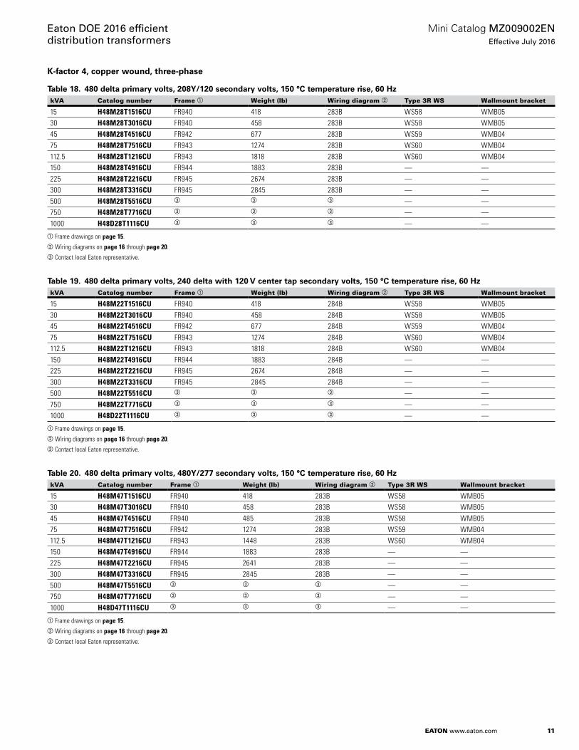
11
Mini Catalog MZ009002ENEffective July 2016
Eaton DOE 2016 efficient distribution transformers
EATON www.eaton.com
K-factor 4, copper wound, three-phase
Table 18. 480 delta primary volts, 208Y/120 secondary volts, 150 °C temperature rise, 60 HzkVA Catalog number Frame a Weight (lb) Wiring diagram b Type 3R WS Wallmount bracket
15 H48M28T1516CU FR940 418 283B WS58 WMB0530 H48M28T3016CU FR940 458 283B WS58 WMB0545 H48M28T4516CU FR942 677 283B WS59 WMB0475 H48M28T7516CU FR943 1274 283B WS60 WMB04112.5 H48M28T1216CU FR943 1818 283B WS60 WMB04150 H48M28T4916CU FR944 1883 283B — —225 H48M28T2216CU FR945 2674 283B — —300 H48M28T3316CU FR945 2845 283B — —500 H48M28T5516CU c c c — —750 H48M28T7716CU c c c — —1000 H48D28T1116CU c c c — —
aFrame drawings on page 15.bWiring diagrams on page 16 through page 20.cContact local Eaton representative.
Table 19. 480 delta primary volts, 240 delta with 120 V center tap secondary volts, 150 °C temperature rise, 60 HzkVA Catalog number Frame a Weight (lb) Wiring diagram b Type 3R WS Wallmount bracket
15 H48M22T1516CU FR940 418 284B WS58 WMB0530 H48M22T3016CU FR940 458 284B WS58 WMB0545 H48M22T4516CU FR942 677 284B WS59 WMB0475 H48M22T7516CU FR943 1274 284B WS60 WMB04112.5 H48M22T1216CU FR943 1818 284B WS60 WMB04150 H48M22T4916CU FR944 1883 284B — —225 H48M22T2216CU FR945 2674 284B — —300 H48M22T3316CU FR945 2845 284B — —500 H48M22T5516CU c c c — —750 H48M22T7716CU c c c — —1000 H48D22T1116CU c c c — —
aFrame drawings on page 15.bWiring diagrams on page 16 through page 20.cContact local Eaton representative.
Table 20. 480 delta primary volts, 480Y/277 secondary volts, 150 °C temperature rise, 60 HzkVA Catalog number Frame a Weight (lb) Wiring diagram b Type 3R WS Wallmount bracket
15 H48M47T1516CU FR940 418 283B WS58 WMB0530 H48M47T3016CU FR940 458 283B WS58 WMB0545 H48M47T4516CU FR940 485 283B WS58 WMB0575 H48M47T7516CU FR942 1274 283B WS59 WMB04112.5 H48M47T1216CU FR943 1448 283B WS60 WMB04150 H48M47T4916CU FR944 1883 283B — —225 H48M47T2216CU FR945 2641 283B — —300 H48M47T3316CU FR945 2845 283B — —500 H48M47T5516CU c c c — —750 H48M47T7716CU c c c — —1000 H48D47T1116CU c c c — —
aFrame drawings on page 15.bWiring diagrams on page 16 through page 20.cContact local Eaton representative.
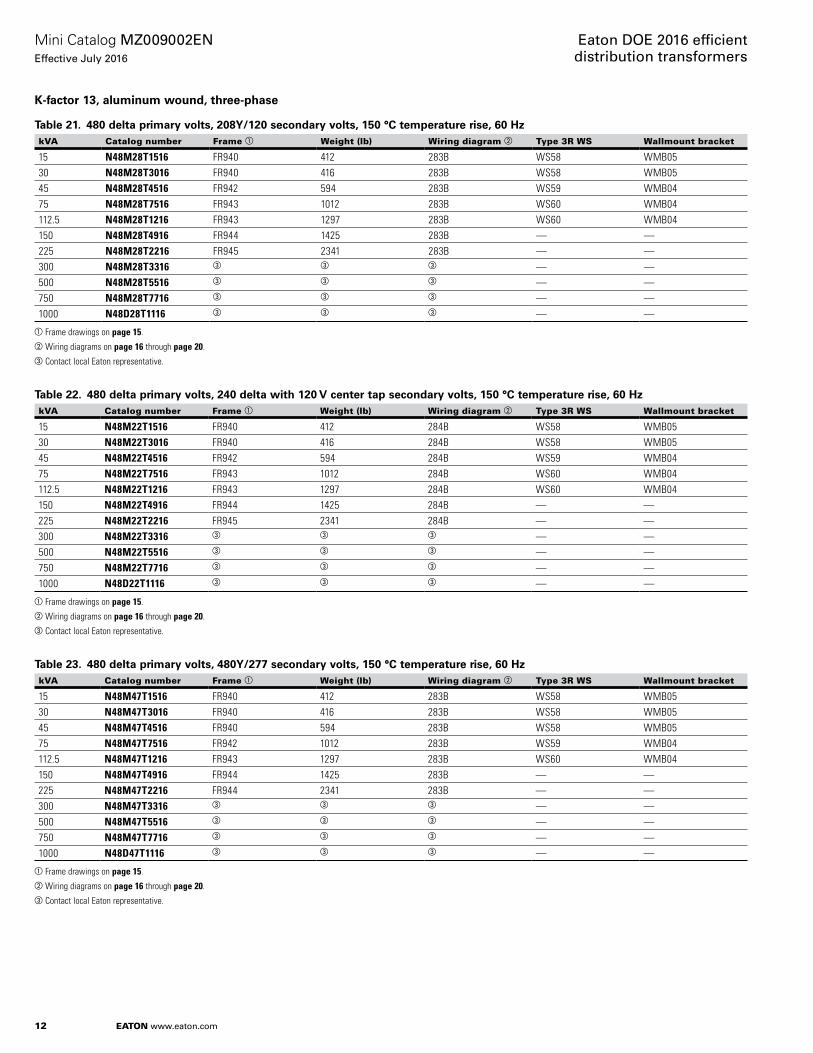
12
Mini Catalog MZ009002ENEffective July 2016
Eaton DOE 2016 efficient distribution transformers
EATON www.eaton.com
K-factor 13, aluminum wound, three-phase
Table 21. 480 delta primary volts, 208Y/120 secondary volts, 150 °C temperature rise, 60 HzkVA Catalog number Frame a Weight (lb) Wiring diagram b Type 3R WS Wallmount bracket
15 N48M28T1516 FR940 412 283B WS58 WMB0530 N48M28T3016 FR940 416 283B WS58 WMB0545 N48M28T4516 FR942 594 283B WS59 WMB0475 N48M28T7516 FR943 1012 283B WS60 WMB04112.5 N48M28T1216 FR943 1297 283B WS60 WMB04150 N48M28T4916 FR944 1425 283B — —225 N48M28T2216 FR945 2341 283B — —300 N48M28T3316 c c c — —500 N48M28T5516 c c c — —750 N48M28T7716 c c c — —1000 N48D28T1116 c c c — —
aFrame drawings on page 15.bWiring diagrams on page 16 through page 20.cContact local Eaton representative.
Table 22. 480 delta primary volts, 240 delta with 120 V center tap secondary volts, 150 °C temperature rise, 60 HzkVA Catalog number Frame a Weight (lb) Wiring diagram b Type 3R WS Wallmount bracket
15 N48M22T1516 FR940 412 284B WS58 WMB0530 N48M22T3016 FR940 416 284B WS58 WMB0545 N48M22T4516 FR942 594 284B WS59 WMB0475 N48M22T7516 FR943 1012 284B WS60 WMB04112.5 N48M22T1216 FR943 1297 284B WS60 WMB04150 N48M22T4916 FR944 1425 284B — —225 N48M22T2216 FR945 2341 284B — —300 N48M22T3316 c c c — —500 N48M22T5516 c c c — —750 N48M22T7716 c c c — —1000 N48D22T1116 c c c — —
aFrame drawings on page 15.bWiring diagrams on page 16 through page 20.cContact local Eaton representative.
Table 23. 480 delta primary volts, 480Y/277 secondary volts, 150 °C temperature rise, 60 HzkVA Catalog number Frame a Weight (lb) Wiring diagram b Type 3R WS Wallmount bracket
15 N48M47T1516 FR940 412 283B WS58 WMB0530 N48M47T3016 FR940 416 283B WS58 WMB0545 N48M47T4516 FR940 594 283B WS58 WMB0575 N48M47T7516 FR942 1012 283B WS59 WMB04112.5 N48M47T1216 FR943 1297 283B WS60 WMB04150 N48M47T4916 FR944 1425 283B — —225 N48M47T2216 FR944 2341 283B — —300 N48M47T3316 c c c — —500 N48M47T5516 c c c — —750 N48M47T7716 c c c — —1000 N48D47T1116 c c c — —
aFrame drawings on page 15.bWiring diagrams on page 16 through page 20.cContact local Eaton representative.
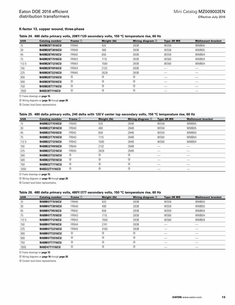
13
Mini Catalog MZ009002ENEffective July 2016
Eaton DOE 2016 efficient distribution transformers
EATON www.eaton.com
K-factor 13, copper wound, three-phase
Table 24. 480 delta primary volts, 208Y/120 secondary volts, 150 °C temperature rise, 60 HzkVA Catalog number Frame a Weight (lb) Wiring diagram b Type 3R WS Wallmount bracket
15 N48M28T1516CU FR940 420 283B WS58 WMB0530 N48M28T3016CU FR940 480 283B WS58 WMB0545 N48M28T4516CU FR942 658 283B WS59 WMB0475 N48M28T7516CU FR943 1115 283B WS60 WMB04112.5 N48M28T1216CU FR943 1500 283B WS60 WMB04150 N48M28T4916CU FR944 2132 283B — —225 N48M28T2216CU FR945 2628 283B — —300 N48M28T3316CU c c c — —500 N48M28T5516CU c c c — —750 N48M28T7716CU c c c — —1000 N48D28T1116CU c c c — —
aFrame drawings on page 15.bWiring diagrams on page 16 through page 20.cContact local Eaton representative.
Table 25. 480 delta primary volts, 240 delta with 120 V center tap secondary volts, 150 °C temperature rise, 60 HzkVA Catalog number Frame a Weight (lb) Wiring diagram b Type 3R WS Wallmount bracket
15 N48M22T1516CU FR940 420 284B WS58 WMB0530 N48M22T3016CU FR940 480 284B WS58 WMB0545 N48M22T4516CU FR942 658 284B WS59 WMB0475 N48M22T7516CU FR943 1115 284B WS60 WMB04112.5 N48M22T1216CU FR943 1500 284B WS60 WMB04150 N48M22T4916CU FR944 2132 284B — —225 N48M22T2216CU FR945 2628 284B — —300 N48M22T3316CU c c c — —500 N48M22T5516CU c c c — —750 N48M22T7716CU c c c — —1000 N48D22T1116CU c c c — —
aFrame drawings on page 15.bWiring diagrams on page 16 through page 20.cContact local Eaton representative.
Table 26. 480 delta primary volts, 480Y/277 secondary volts, 150 °C temperature rise, 60 HzkVA Catalog number Frame a Weight (lb) Wiring diagram b Type 3R WS Wallmount bracket
15 N48M47T1516CU FR940 420 283B WS58 WMB0530 N48M47T3016CU FR940 480 283B WS58 WMB0545 N48M47T4516CU FR942 658 283B WS59 WMB0475 N48M47T7516CU FR943 1115 283B WS60 WMB04112.5 N48M47T1216CU FR943 1500 283B WS60 WMB04150 N48M47T4916CU FR944 2741 283B — —225 N48M47T2216CU FR945 3100 283B — —300 N48M47T3316CU c c c — —500 N48M47T5516CU c c c — —750 N48M47T7716CU c c c — —1000 N48D47T1116CU c c c — —
aFrame drawings on page 15.bWiring diagrams on page 16 through page 20.cContact local Eaton representative.
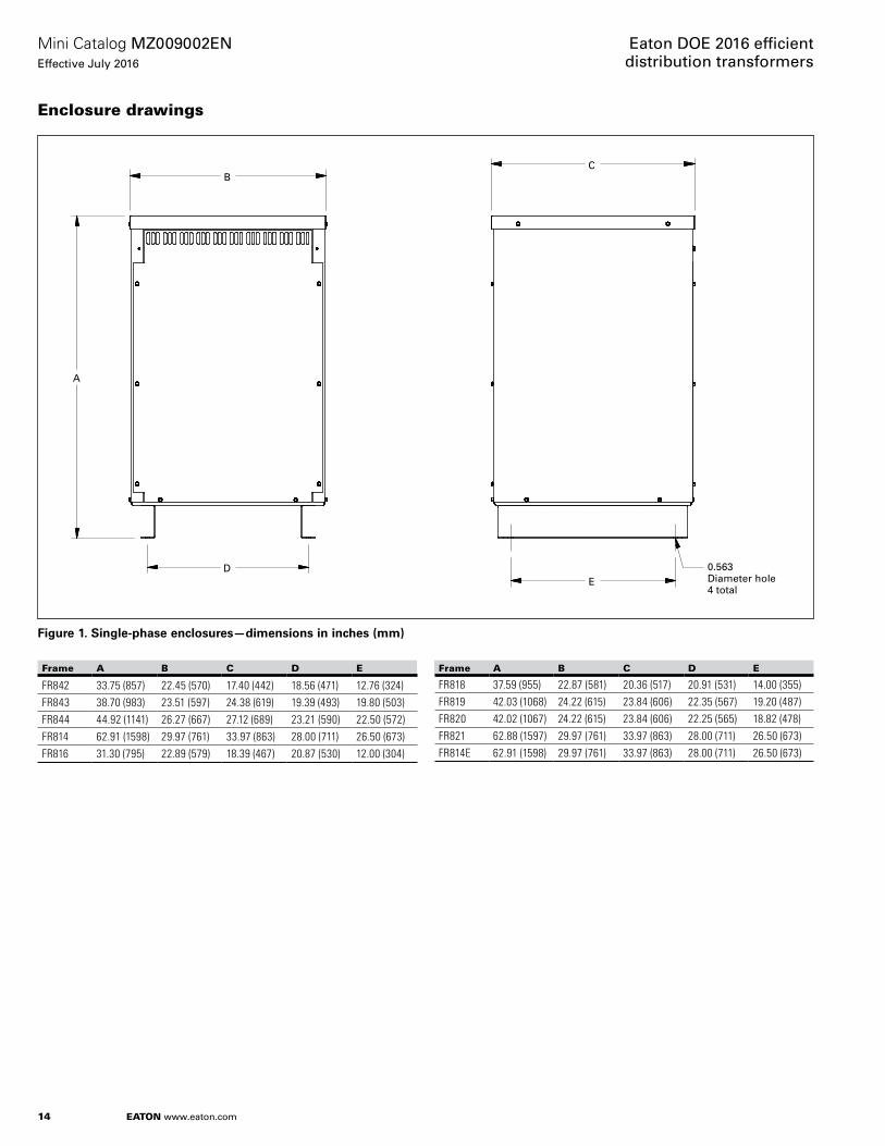
14
Mini Catalog MZ009002ENEffective July 2016
Eaton DOE 2016 efficient distribution transformers
EATON www.eaton.com
Enclosure drawings
B
A
DE
C
0.563 Diameter hole4 total
Figure 1. Single-phase enclosures—dimensions in inches (mm)
Frame A B C D E
FR842 33.75 (857) 22.45 (570) 17.40 (442) 18.56 (471) 12.76 (324)FR843 38.70 (983) 23.51 (597) 24.38 (619) 19.39 (493) 19.80 (503)FR844 44.92 (1141) 26.27 (667) 27.12 (689) 23.21 (590) 22.50 (572)FR814 62.91 (1598) 29.97 (761) 33.97 (863) 28.00 (711) 26.50 (673)FR816 31.30 (795) 22.89 (579) 18.39 (467) 20.87 (530) 12.00 (304)
Frame A B C D E
FR818 37.59 (955) 22.87 (581) 20.36 (517) 20.91 (531) 14.00 (355)FR819 42.03 (1068) 24.22 (615) 23.84 (606) 22.35 (567) 19.20 (487)FR820 42.02 (1067) 24.22 (615) 23.84 (606) 22.25 (565) 18.82 (478)FR821 62.88 (1597) 29.97 (761) 33.97 (863) 28.00 (711) 26.50 (673)FR814E 62.91 (1598) 29.97 (761) 33.97 (863) 28.00 (711) 26.50 (673)
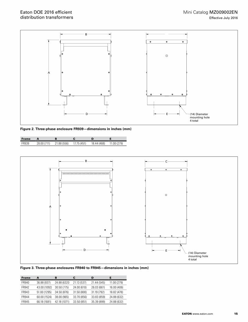
15
Mini Catalog MZ009002ENEffective July 2016
Eaton DOE 2016 effi cient distribution transformers
EATON www.eaton.com
B
ED
A
(14) Diametermounting hole4 total
Figure 2. Three-phase enclosure FR939—dimensions in inches (mm)
Frame A B C D E
FR939 28.00 (711) 21.88 (556) 17.75 (451) 18.44 (468) 11.00 (279)
B
ED
A
(14) Diametermounting hole4 total
C
Figure 3. Three-phase enclosures FR940 to FR945—dimensions in inches (mm)
Frame A B C D E
FR940 36.88 (937) 24.88 (6320 21.13 (537) 21.44 (545) 11.00 (279)FR942 43.00 (1092) 30.50 (775) 24.00 (610) 26.03 (661) 16.00 (406)FR943 51.00 (1295) 34.50 (876) 31.50 (800) 31.19 (792) 18.82 (478)FR944 60.00 (1524) 38.00 (965) 33.70 (856) 33.83 (859) 24.88 (632)FR945 66.18 (1681) 42.18 (1071) 33.50 (851) 35.39 (899) 24.88 (632)
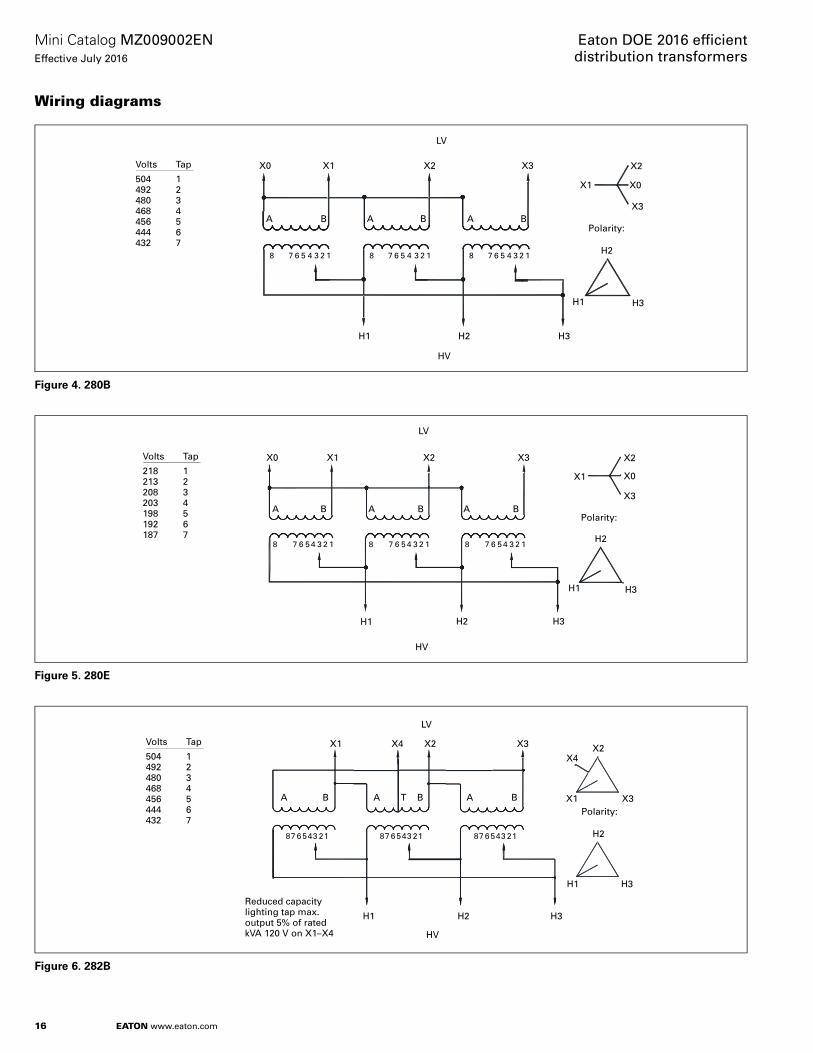
16
Mini Catalog MZ009002ENEffective July 2016
Eaton DOE 2016 effi cient distribution transformers
EATON www.eaton.com
Wiring diagrams
Volts Tap
504 1492 2480 3468 4456 5444 6432 7
LV
X0 X1 X2 X3
A B A B A B
X2
X1
X3
X0
Polarity:
H2
H3H1
H2 H3H1
HV
8 7 6 5 4 3 2 1 8 7 6 5 4 3 2 1 8 7 6 5 4 3 2 1
Figure 4. 280B
Volts Tap
218 1213 2208 3203 4198 5192 6187 7
LV
X0 X1 X2 X3
A B A B A B
X2
X1
X3
X0
Polarity:
H2
H3H1
H2 H3H1
HV
8 7 6 5 4 3 2 1 8 7 6 5 4 3 2 1 8 7 6 5 4 3 2 1
Figure 5. 280E
Volts Tap
504 1492 2480 3468 4456 5444 6432 7
LV
X1 X2 X3
A B A BT A B
X2
X1 X3
X4
Polarity:
H2
H3H1
H2 H3H1
HV
87 6 543 21 87 6 543 21 87 6 543 21
X4
Reduced capacitylighting tap max.output 5% of ratedkVA 120 V on X1–X4
Figure 6. 282B
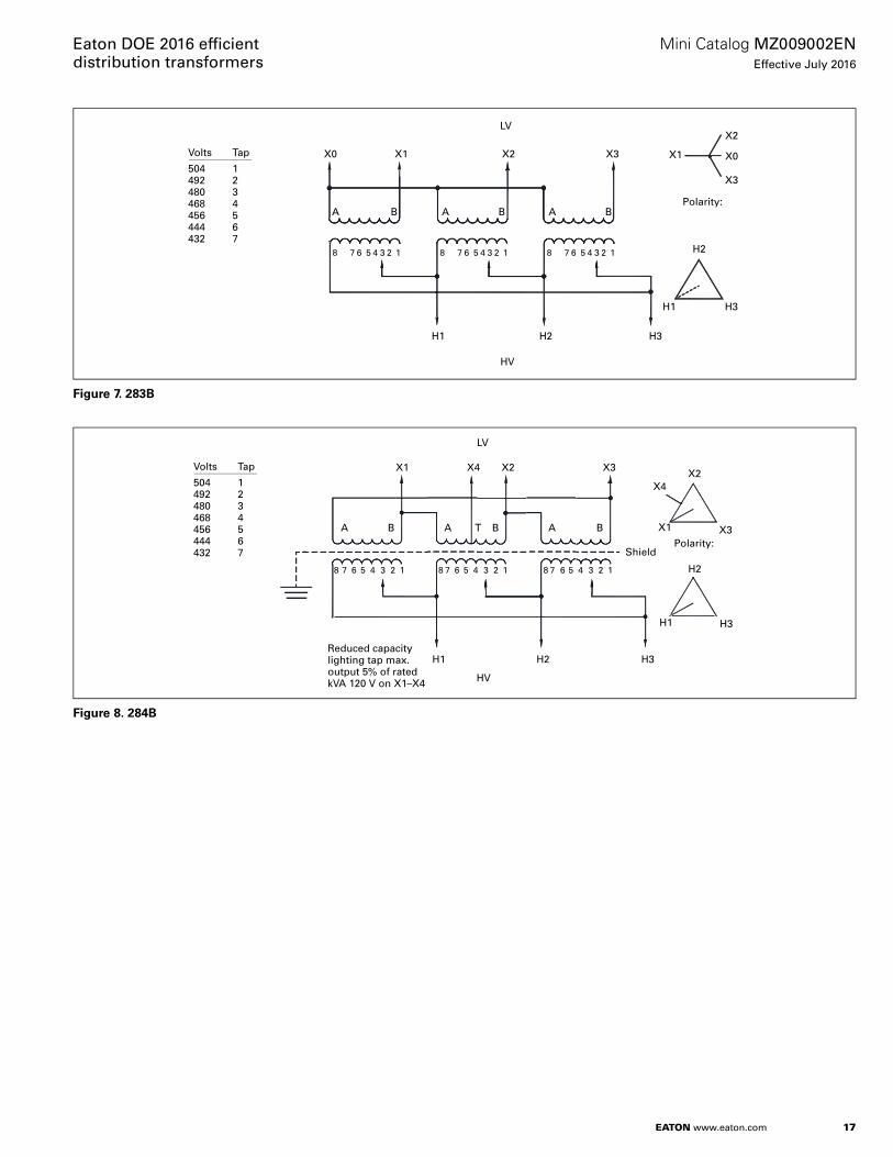
17
Mini Catalog MZ009002ENEffective July 2016
Eaton DOE 2016 effi cient distribution transformers
EATON www.eaton.com
Volts Tap
504 1492 2480 3468 4456 5444 6432 7
LV
X0 X1 X2 X3
A B A B A B
X2
X1
X3
X0
Polarity:
H2
H3H1
H2 H3H1
HV
8 7 6 5 4 3 2 1 8 7 6 5 4 3 2 1 8 7 6 5 4 3 2 1
Figure 7. 283B
Volts Tap
504 1492 2480 3468 4456 5444 6432 7
LV
X4X1 X2 X3
A B A BT A B
X2
X1 X3
X4
Polarity:
H2
H3H1
H2 H3H1
HV
8 7 6 5 4 3 2 1 8 7 6 5 4 3 2 1 8 7 6 5 4 3 2 1
Shield
Reduced capacitylighting tap max.output 5% of ratedkVA 120 V on X1–X4
Figure 8. 284B
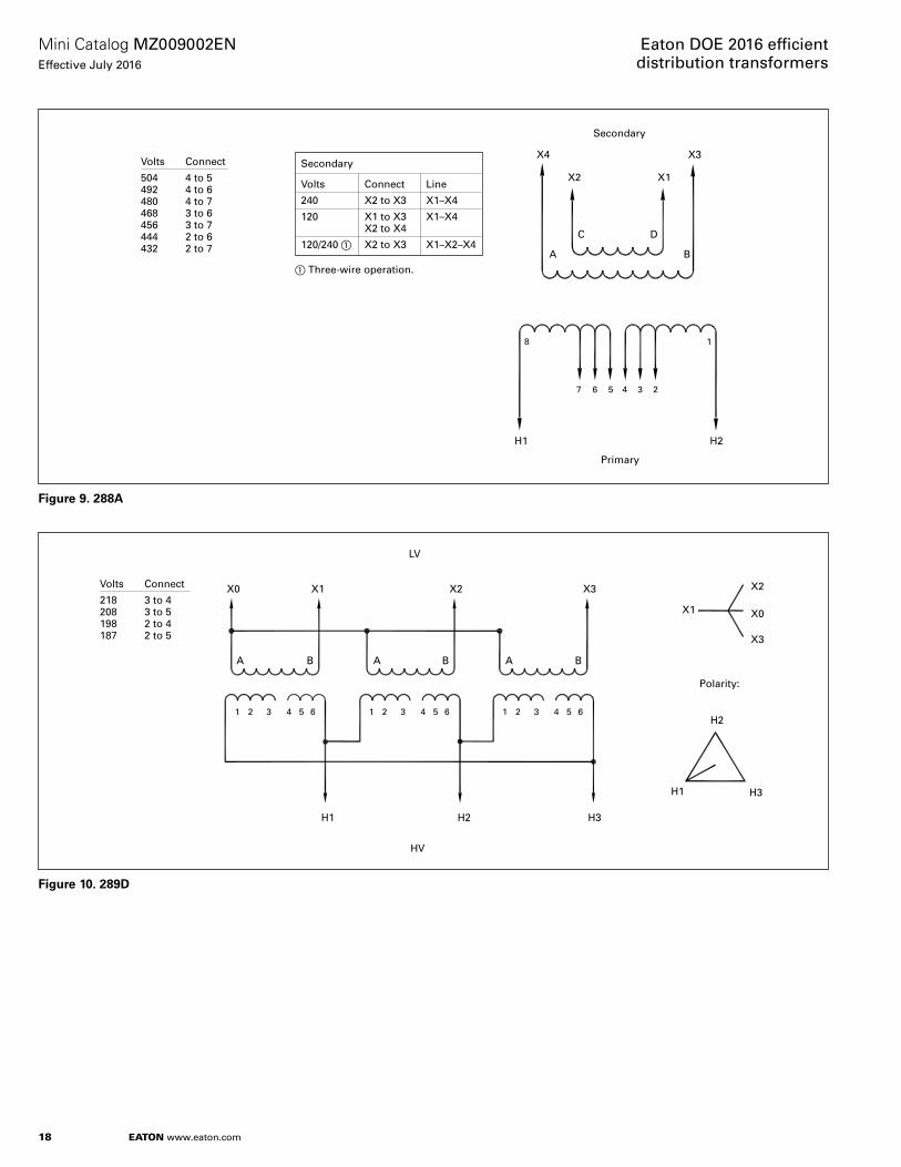
18
Mini Catalog MZ009002ENEffective July 2016
Eaton DOE 2016 efficient distribution transformers
EATON www.eaton.com
Volts Connect
504 4 to 5492 4 to 6480 4 to 7468 3 to 6456 3 to 7444 2 to 6432 2 to 7
Secondary
X4 X3
X1X2
A B
C D
H2H1
Primary
8
7 6 5 4 3 2
1
Secondary
Volts Connect Line
240 X2 to X3 X1–X4
120 X1 to X3 X1–X4 X2 to X4
120/240 � X2 to X3 X1–X2–X4
� Three-wire operation.
Figure 9. 288A
Volts Connect
218 3 to 4208 3 to 5198 2 to 4187 2 to 5
LV
X0 X1 X2 X3
A B A B A B
X2
X1
X3
X0
Polarity:
H2
H3H1
H2 H3H1
HV
654321 654321 654321
Figure 10. 289D
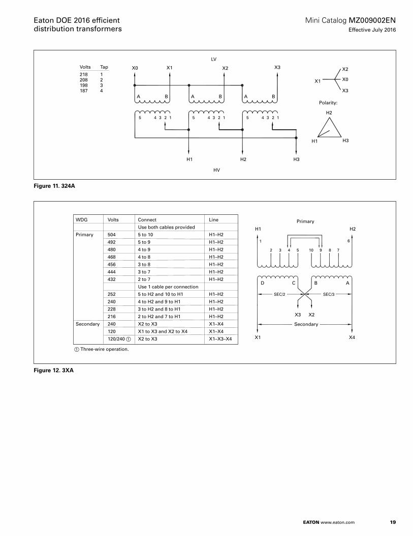
19
Mini Catalog MZ009002ENEffective July 2016
Eaton DOE 2016 efficient distribution transformers
EATON www.eaton.com
Volts Tap
218 1208 2198 3187 4
LV
X0 X3X1 X2
A B A B A B
X2
X1
X3
X0
Polarity:
H2
H3H1
H2 H3H1
HV
5 4 3 2 1 5 4 3 2 1 5 4 3 2 1
Figure 11. 324A
Secondary
X4
X3
X1
X2
ABCD
H2H1
Primary
8 7
6
5432
1
WDG Volts Connect Line
Use both cables provided
Primary 504 5 to 10 H1–H2
492 5 to 9 H1–H2
480 4 to 9 H1–H2
468 4 to 8 H1–H2
456 3 to 8 H1–H2
444 3 to 7 H1–H2
432 2 to 7 H1–H2
Use 1 cable per connection
252 5 to H2 and 10 to H1 H1–H2
240 4 to H2 and 9 to H1 H1–H2
228 3 to H2 and 8 to H1 H1–H2
216 2 to H2 and 7 to H1 H1–H2
Secondary 240 X2 to X3 X1–X4
120 X1 to X3 and X2 to X4 X1–X4
120/240 � X2 to X3 X1–X3–X4
� Three-wire operation.
910
SEC/2 SEC/3
Figure 12. 3XA
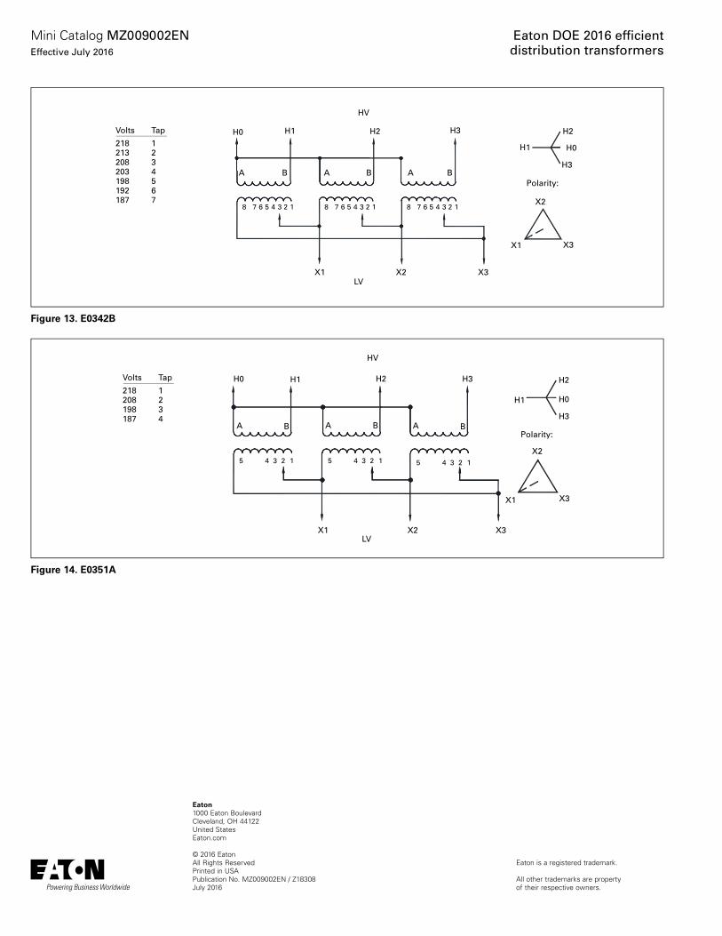
Eaton1000 Eaton BoulevardCleveland, OH 44122United StatesEaton.com
© 2016 EatonAll Rights ReservedPrinted in USAPublication No. MZ009002EN / Z18308July 2016
Eaton is a registered trademark.
All other trademarks are property of their respective owners.
Eaton DOE 2016 effi cient distribution transformers
Mini Catalog MZ009002ENEffective July 2016
Volts Tap
218 1213 2208 3203 4198 5192 6187 7
HV
H1 H2 H3
A B A B A B
H2
H1
H3
Polarity:
X2
X3X1
X2 X3X1LV
8 7 6 5 4 3 2 1 8 7 6 5 4 3 2 1 8 7 6 5 4 3 2 1
H0
H0
Figure 13. E0342B
Volts Tap
218 1208 2198 3187 4
HV
H1 H2 H3
A B A B A B
H2
H1
H3
Polarity:
X2
X3X1
X2 X3X1LV
5 4 3 2 1 5 4 3 2 1 5 4 3 2 1
H0
H0
Figure 14. E0351A
Related Documents